WO2018074325A1 - 蓄電池電車用蓄電池装置及び蓄電池電車 - Google Patents
蓄電池電車用蓄電池装置及び蓄電池電車 Download PDFInfo
- Publication number
- WO2018074325A1 WO2018074325A1 PCT/JP2017/037051 JP2017037051W WO2018074325A1 WO 2018074325 A1 WO2018074325 A1 WO 2018074325A1 JP 2017037051 W JP2017037051 W JP 2017037051W WO 2018074325 A1 WO2018074325 A1 WO 2018074325A1
- Authority
- WO
- WIPO (PCT)
- Prior art keywords
- storage battery
- battery device
- storage
- fire extinguishing
- main circuit
- Prior art date
- Legal status (The legal status is an assumption and is not a legal conclusion. Google has not performed a legal analysis and makes no representation as to the accuracy of the status listed.)
- Ceased
Links
Images




Classifications
-
- B—PERFORMING OPERATIONS; TRANSPORTING
- B60—VEHICLES IN GENERAL
- B60L—PROPULSION OF ELECTRICALLY-PROPELLED VEHICLES; SUPPLYING ELECTRIC POWER FOR AUXILIARY EQUIPMENT OF ELECTRICALLY-PROPELLED VEHICLES; ELECTRODYNAMIC BRAKE SYSTEMS FOR VEHICLES IN GENERAL; MAGNETIC SUSPENSION OR LEVITATION FOR VEHICLES; MONITORING OPERATING VARIABLES OF ELECTRICALLY-PROPELLED VEHICLES; ELECTRIC SAFETY DEVICES FOR ELECTRICALLY-PROPELLED VEHICLES
- B60L3/00—Electric devices on electrically-propelled vehicles for safety purposes; Monitoring operating variables, e.g. speed, deceleration or energy consumption
-
- A—HUMAN NECESSITIES
- A62—LIFE-SAVING; FIRE-FIGHTING
- A62C—FIRE-FIGHTING
- A62C3/00—Fire prevention, containment or extinguishing specially adapted for particular objects or places
- A62C3/07—Fire prevention, containment or extinguishing specially adapted for particular objects or places in vehicles, e.g. in road vehicles
-
- A—HUMAN NECESSITIES
- A62—LIFE-SAVING; FIRE-FIGHTING
- A62C—FIRE-FIGHTING
- A62C3/00—Fire prevention, containment or extinguishing specially adapted for particular objects or places
- A62C3/16—Fire prevention, containment or extinguishing specially adapted for particular objects or places in electrical installations, e.g. cableways
-
- A—HUMAN NECESSITIES
- A62—LIFE-SAVING; FIRE-FIGHTING
- A62C—FIRE-FIGHTING
- A62C35/00—Permanently-installed equipment
- A62C35/02—Permanently-installed equipment with containers for delivering the extinguishing substance
- A62C35/10—Containers destroyed or opened by flames or heat
-
- B—PERFORMING OPERATIONS; TRANSPORTING
- B60—VEHICLES IN GENERAL
- B60L—PROPULSION OF ELECTRICALLY-PROPELLED VEHICLES; SUPPLYING ELECTRIC POWER FOR AUXILIARY EQUIPMENT OF ELECTRICALLY-PROPELLED VEHICLES; ELECTRODYNAMIC BRAKE SYSTEMS FOR VEHICLES IN GENERAL; MAGNETIC SUSPENSION OR LEVITATION FOR VEHICLES; MONITORING OPERATING VARIABLES OF ELECTRICALLY-PROPELLED VEHICLES; ELECTRIC SAFETY DEVICES FOR ELECTRICALLY-PROPELLED VEHICLES
- B60L58/00—Methods or circuit arrangements for monitoring or controlling batteries or fuel cells, specially adapted for electric vehicles
- B60L58/10—Methods or circuit arrangements for monitoring or controlling batteries or fuel cells, specially adapted for electric vehicles for monitoring or controlling batteries
- B60L58/24—Methods or circuit arrangements for monitoring or controlling batteries or fuel cells, specially adapted for electric vehicles for monitoring or controlling batteries for controlling the temperature of batteries
-
- B—PERFORMING OPERATIONS; TRANSPORTING
- B61—RAILWAYS
- B61C—LOCOMOTIVES; MOTOR RAILCARS
- B61C3/00—Electric locomotives or railcars
- B61C3/02—Electric locomotives or railcars with electric accumulators
-
- H—ELECTRICITY
- H01—ELECTRIC ELEMENTS
- H01M—PROCESSES OR MEANS, e.g. BATTERIES, FOR THE DIRECT CONVERSION OF CHEMICAL ENERGY INTO ELECTRICAL ENERGY
- H01M10/00—Secondary cells; Manufacture thereof
- H01M10/05—Accumulators with non-aqueous electrolyte
- H01M10/052—Li-accumulators
- H01M10/0525—Rocking-chair batteries, i.e. batteries with lithium insertion or intercalation in both electrodes; Lithium-ion batteries
-
- H—ELECTRICITY
- H01—ELECTRIC ELEMENTS
- H01M—PROCESSES OR MEANS, e.g. BATTERIES, FOR THE DIRECT CONVERSION OF CHEMICAL ENERGY INTO ELECTRICAL ENERGY
- H01M50/00—Constructional details or processes of manufacture of the non-active parts of electrochemical cells other than fuel cells, e.g. hybrid cells
- H01M50/20—Mountings; Secondary casings or frames; Racks, modules or packs; Suspension devices; Shock absorbers; Transport or carrying devices; Holders
- H01M50/204—Racks, modules or packs for multiple batteries or multiple cells
- H01M50/207—Racks, modules or packs for multiple batteries or multiple cells characterised by their shape
- H01M50/213—Racks, modules or packs for multiple batteries or multiple cells characterised by their shape adapted for cells having curved cross-section, e.g. round or elliptic
-
- H—ELECTRICITY
- H01—ELECTRIC ELEMENTS
- H01M—PROCESSES OR MEANS, e.g. BATTERIES, FOR THE DIRECT CONVERSION OF CHEMICAL ENERGY INTO ELECTRICAL ENERGY
- H01M50/00—Constructional details or processes of manufacture of the non-active parts of electrochemical cells other than fuel cells, e.g. hybrid cells
- H01M50/20—Mountings; Secondary casings or frames; Racks, modules or packs; Suspension devices; Shock absorbers; Transport or carrying devices; Holders
- H01M50/233—Mountings; Secondary casings or frames; Racks, modules or packs; Suspension devices; Shock absorbers; Transport or carrying devices; Holders characterised by physical properties of casings or racks, e.g. dimensions
- H01M50/24—Mountings; Secondary casings or frames; Racks, modules or packs; Suspension devices; Shock absorbers; Transport or carrying devices; Holders characterised by physical properties of casings or racks, e.g. dimensions adapted for protecting batteries from their environment, e.g. from corrosion
-
- H—ELECTRICITY
- H01—ELECTRIC ELEMENTS
- H01M—PROCESSES OR MEANS, e.g. BATTERIES, FOR THE DIRECT CONVERSION OF CHEMICAL ENERGY INTO ELECTRICAL ENERGY
- H01M50/00—Constructional details or processes of manufacture of the non-active parts of electrochemical cells other than fuel cells, e.g. hybrid cells
- H01M50/30—Arrangements for facilitating escape of gases
-
- H—ELECTRICITY
- H02—GENERATION; CONVERSION OR DISTRIBUTION OF ELECTRIC POWER
- H02J—ELECTRIC POWER NETWORKS; CIRCUIT ARRANGEMENTS OR SYSTEMS FOR SUPPLYING OR DISTRIBUTING ELECTRIC POWER; SYSTEMS FOR STORING ELECTRIC ENERGY
- H02J7/00—Circuit arrangements for charging or discharging batteries or for supplying loads from batteries
-
- H—ELECTRICITY
- H01—ELECTRIC ELEMENTS
- H01M—PROCESSES OR MEANS, e.g. BATTERIES, FOR THE DIRECT CONVERSION OF CHEMICAL ENERGY INTO ELECTRICAL ENERGY
- H01M2200/00—Safety devices for primary or secondary batteries
- H01M2200/20—Pressure-sensitive devices
-
- H—ELECTRICITY
- H01—ELECTRIC ELEMENTS
- H01M—PROCESSES OR MEANS, e.g. BATTERIES, FOR THE DIRECT CONVERSION OF CHEMICAL ENERGY INTO ELECTRICAL ENERGY
- H01M2220/00—Batteries for particular applications
- H01M2220/20—Batteries in motive systems, e.g. vehicle, ship, plane
-
- Y—GENERAL TAGGING OF NEW TECHNOLOGICAL DEVELOPMENTS; GENERAL TAGGING OF CROSS-SECTIONAL TECHNOLOGIES SPANNING OVER SEVERAL SECTIONS OF THE IPC; TECHNICAL SUBJECTS COVERED BY FORMER USPC CROSS-REFERENCE ART COLLECTIONS [XRACs] AND DIGESTS
- Y02—TECHNOLOGIES OR APPLICATIONS FOR MITIGATION OR ADAPTATION AGAINST CLIMATE CHANGE
- Y02E—REDUCTION OF GREENHOUSE GAS [GHG] EMISSIONS, RELATED TO ENERGY GENERATION, TRANSMISSION OR DISTRIBUTION
- Y02E60/00—Enabling technologies; Technologies with a potential or indirect contribution to GHG emissions mitigation
- Y02E60/10—Energy storage using batteries
-
- Y—GENERAL TAGGING OF NEW TECHNOLOGICAL DEVELOPMENTS; GENERAL TAGGING OF CROSS-SECTIONAL TECHNOLOGIES SPANNING OVER SEVERAL SECTIONS OF THE IPC; TECHNICAL SUBJECTS COVERED BY FORMER USPC CROSS-REFERENCE ART COLLECTIONS [XRACs] AND DIGESTS
- Y02—TECHNOLOGIES OR APPLICATIONS FOR MITIGATION OR ADAPTATION AGAINST CLIMATE CHANGE
- Y02T—CLIMATE CHANGE MITIGATION TECHNOLOGIES RELATED TO TRANSPORTATION
- Y02T10/00—Road transport of goods or passengers
- Y02T10/60—Other road transportation technologies with climate change mitigation effect
- Y02T10/70—Energy storage systems for electromobility, e.g. batteries
Definitions
- the present invention relates to a storage battery device mounted on a storage battery train.
- a main conversion circuit connected to a secondary winding of a main transformer to supply drive power to a main motor, and a tertiary winding of a main transformer connected to a power supply to an accessory
- a main conversion circuit that is connected to the secondary winding of the main transformer and supplies drive power to the main motor.
- a stationary inverter for supplying power to an auxiliary device is connected to a direct current stage of a main conversion circuit including the above, and a storage battery is connected via a bidirectional chopper (see Patent Document 2).
- the object of the present invention relates to preventing or extinguishing the storage battery device when the storage battery device mounted on the storage battery train is shorted or crushed externally.
- a main circuit storage battery box divided into a plurality of equipment chambers, a plurality of storage battery units respectively stored in the plurality of equipment chambers, and a plurality of pressure release mechanisms respectively installed in the plurality of equipment chambers
- the storage battery device according to claim 1, wherein the plurality of pressure release mechanisms discharge the gas when a plurality of storage battery units generate gas.
- a main circuit storage battery box divided into a plurality of equipment rooms, a plurality of storage battery units respectively accommodated in the plurality of equipment rooms, and a plurality of automatic fire extinguishing mechanisms respectively disposed in the plurality of equipment rooms.
- the plurality of automatic fire extinguishing mechanisms relate to the storage battery device that extinguishes each of the plurality of storage battery units when it fires.
- the main circuit storage battery box is divided into small areas, each is provided with a pressure release mechanism, and the storage battery is housed.
- Pressure rapidly increases and the ignitable gas is exhausted from the pressure release mechanism (if not divided into small areas, even if the ignitable gas is generated, the pressure does not increase and the pressure release mechanism does not release it, and the fire become).
- the fire can be extinguished only in that region. The fire does not spread to other areas.
- the state accompanying the abnormality of the storage battery device mounted in the storage battery train occurs, the state accompanying the abnormality of the storage battery device can be automatically suppressed or recovered.
- BRIEF DESCRIPTION OF THE DRAWINGS It is a whole block diagram of the power system for storage battery electric trains concerning an Example. It is a perspective view of the main circuit storage battery box concerning an example. It is a perspective view of a storage battery unit concerning an example. It is a perspective view of a storage battery module concerning an example. It is a principal part block diagram of the automatic fire extinguishing mechanism concerning an Example. It is a principal part block diagram of the pressure release mechanism concerning an Example.
- a main circuit storage battery box divided into a plurality of equipment chambers, a plurality of storage battery units respectively stored in the plurality of equipment chambers, and a plurality of pressure release mechanisms respectively installed in the plurality of equipment chambers
- a storage battery device is disclosed, wherein the plurality of pressure release mechanisms discharge each of the plurality of storage battery units when gas is generated.
- the main circuit storage battery box includes a pressure release mechanism for discharging the gas in the main circuit storage battery box to the outside.
- the examples also disclose that a plurality of pressure relief mechanisms are installed at the bottom of the main circuit storage box.
- the pressure release mechanism is a valve that discharges the gas in the device chamber to the outside when the pressure in the device chamber exceeds a predetermined pressure.
- a main circuit storage battery box divided into a plurality of equipment rooms, a plurality of storage battery units respectively accommodated in a plurality of equipment rooms, and a plurality of automatic fire extinguishing mechanisms respectively disposed in a plurality of equipment rooms
- the plurality of automatic fire extinguishing mechanisms disclose a storage battery device that extinguishes each of the plurality of storage battery units when it fires.
- the main circuit storage box is provided with an automatic fire extinguishing mechanism for extinguishing the ignited storage battery unit.
- the plurality of automatic fire extinguishing mechanisms are respectively disposed above the plurality of storage battery units accommodated in the same equipment room.
- the automatic fire extinguishing mechanism is a fire extinguishing fluid storage tube which is at least partially melted and discharges the fire extinguishing fluid when the ambient temperature exceeds a predetermined temperature.
- a storage battery unit arrange
- FIG. 1 is a front view of an essential part of a storage battery train showing the present embodiment.
- a plurality of main circuit storage battery boxes 14 are arranged for three banks.
- Each main circuit storage battery box 14 is configured as a box housing a plurality of storage batteries (not shown), and each storage battery converts AC power from a main transformer (not shown) connected to an overhead wire into DC power
- a DC circuit of a main converter (not shown) having a converter for converting and an inverter for converting DC power from the output of the converter into three-phase AC power and outputting it to a main motor (induction motor for wheel drive) It is configured as a DC power supply that supplies DC power.
- FIG. 2 is a whole block diagram of the storage battery electric power system according to the present embodiment.
- the storage battery power system includes a main transformer 52, a main conversion device 54, a breaker box 300, a disconnector 400, a main circuit storage battery 500, and an auxiliary power supply 600.
- the main transformer 52 has a primary winding 56 and a plurality of secondary windings 58 and 60.
- One end of the primary winding 56 is an overhead wire through a vacuum circuit breaker (VCB) 62 and a pantograph 64. It is connected to (AC 20 kV, 60 Hz) 66, and the other end of the primary winding 56 is grounded via the grounding brush 68 of the wheel.
- Each secondary winding 58, 60 is connected to the main converter 54.
- the main conversion device 54 is configured to include a plurality of contacts 70, 72, 74, 76, resistors 78, 80, converters 82, 84, and inverters 86, 88.
- the contacts 70, 72 and the resistor 78 are configured as a charging circuit
- the contacts 74, 76 and the resistor 80 are configured as a charging circuit.
- the contacts 70, 72, 74, 76 are controlled in their opening / closing by controllers (not shown) for controlling the converters 82, 84 and the inverters 86, 88.
- the controller is configured by a computer device provided with information processing resources such as a CPU (Central Processing Unit), a memory, and an input / output interface as control means.
- Capacitors 220 and 224 are connected to the output sides of the converters 82 and 84, respectively.
- the breaker box 300 includes a plurality of resistors 302 and 304, and a plurality of contacts 306, 308, 310, 312 and 314, and the input side (one end of each resistor 302 and 304) is each converter 82,
- the output side (one end side of the contactor 314) is connected to the main circuit storage battery 500 via the disconnecting device 400.
- Disconnector 400 includes switch 402 and switch 404, one end of switch 402 is connected to contact 314, the other end is connected to the high potential side of main circuit storage battery 500, and one end of switch 404 is converter 84. It is connected to the low potential side, and the other end side is connected to the low potential side of the main circuit storage battery 500.
- the main circuit storage battery 500 is composed of a plurality of contacts 502, 504, 506, 508, 510, 512 and a plurality of storage batteries 514, 516, 518.
- the auxiliary power supply device 600 is configured as an auxiliary power supply device for supplying power to an accessory (air conditioner, lighting device), for example, switches an input DC voltage with a semiconductor element, and switches a switched voltage Is composed of a static inverter that smoothes and outputs as an AC voltage.
- inverter power consumption and auxiliary equipment power consumption are taken from the overhead line 66 through the main transformer 52 to the main conversion device 54, and each inverter 86, 88 causes each main motor 250, 252, 254 to , 256, and supplies the output power of each converter 82, 84 to the auxiliary equipment via the auxiliary power supply device 600.
- power conversion operations of the inverters 86 and 88 and the converters 82 and 84 are performed by the controller, and the main circuit storage battery 500 can be charged with the output power of the converters 82 and 84.
- the regenerative electric power (regenerative energy) from each of the main motors 250, 252, 254, 256 is taken into the main conversion device 54 via the respective inverters 86, 88, and the main circuit storage battery is taken with the taken-in regenerative electric power.
- the acquired regenerative electric power is supplied to the accessory via the auxiliary power supply device 600.
- the regenerative power is regenerated to the overhead wire.
- auxiliary power consumption and storage battery charging power are taken from the overhead wire 66 via the main transformer 52 into the main conversion device 54, and the output power of each converter 82, 84 charges the main circuit storage battery 500. And supplies the output power of each converter 82, 84 to the auxiliary equipment via the auxiliary power supply 600. After the charging is completed, the operation of each converter 82, 84 is stopped, and power is supplied from the main circuit storage battery 500 to the auxiliary equipment via the auxiliary power supply device 600.
- each converter 82, 84 At the time of storage battery traveling (power running), the operation of each converter 82, 84 is stopped, the electric power from the main circuit storage battery 500 is taken into the main converter 54, and each inverter 86, 88 drives each main motor 250-256. The power from circuit storage battery 500 is supplied to the accessory via auxiliary power supply device 600. At this time, the power conversion operation of each of the inverters 86 and 88 is executed by the controller, and the power conversion operation of each of the converters 82 and 84 is stopped.
- each converter 82, 84 is stopped, and the regenerated power (regenerated energy) from each main motor 250 to 256 is taken into main conversion device 54 via each inverter 86, 88 and taken.
- the main circuit storage battery 500 is charged with the regenerative power, and the acquired regenerative power is supplied to the auxiliary equipment via the auxiliary power supply device 600.
- each converter 82, 84 and each inverter 86, 88 is stopped, and the power from the main circuit storage battery 500 is supplied to the accessory via the auxiliary power supply device 600.
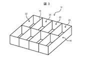
- FIG. 3 is a perspective view of the main circuit storage battery box according to the present embodiment.
- the main circuit storage battery box 14 is a main component of the storage battery device for a storage battery train, and is formed of a metal box 16, and the inside of the box 16 is plural (six The equipment room 20 and the plurality of equipment rooms 22 are separated.
- the storage battery unit 24 is accommodated in each equipment room 20, as shown in FIG. 4, equipment such as a controller or a contact (not shown) is stored.
- the storage battery unit 24 is configured by a plurality of metal frames 26 and the like as a substantially rectangular frame. As shown in FIG. 5, twelve storage battery modules 28 are accommodated in the storage battery unit 24.
- the storage battery module 28 is configured as a storage battery storage case for storing six storage batteries (cells) 30.
- the storage battery module 28 is also configured as a substantially rectangular frame. Under the present circumstances, since 12 storage battery modules 28 in which the six storage batteries 30 were stored are stored in the storage battery unit 24, 72 storage batteries 30 are stored in the storage battery unit 24 as a whole. Since the storage battery unit 24 and the storage battery module 28 are configured as a frame, the longitudinal surface of the stored storage battery 30 is exposed.
- the storage battery modules 28 housed in the storage battery unit 24 are connected in series with each other via a conductor bar 32 (see FIG. 4), and the storage batteries 30 are connected in series with each other in the storage battery module 28. That is, the 72 storage batteries 30 in the storage battery unit 24 are connected in series with each other.
- a lithium ion battery can be used as the storage battery 30, for example.
- a plurality of cooling fans 38 for cooling the storage battery 30, which generates heat due to release charging, and an automatic fire extinguishing mechanism 34 are provided on the top (top plate) of the storage battery unit 24 housed in each equipment room 20. Is arranged.
- the automatic fire extinguishing mechanism 34 has a extinguishing fluid storage container or a extinguishing fluid storage tube 36 as a extinguishing fluid storage means, and a extinguishing fluid (not shown) is stored in the extinguishing fluid storage tube 36. Since the automatic fire extinguishing mechanism 34 is disposed above the storage battery unit 24, when the storage battery 30 is ignited, the ambient temperature of the automatic fire extinguishing mechanism 34 is immediately raised by the updraft.
- the fire extinguishing fluid storage tube 36 is made of a material that is at least partially melted when the ambient temperature exceeds the set temperature and discharges the fire extinguishing fluid. Under the present circumstances, for example, when storage battery 30 short-circuits or storage battery 30 is crushed by pressure from the outside and fires from storage battery 30, and ambient temperature exceeds preset temperature, a part of fire extinguishing fluid storage tube 36 As it melts, the extinguishing fluid is discharged into the storage battery unit 24. Since the storage battery unit 24 is disposed at the lower part of the automatic fire extinguishing mechanism 34, the discharged extinguishing fluid naturally permeates to the lower part of the storage battery unit 24 and covers the storage battery 30 which has ignited.
- the extinguishing fluid storage tube 36 can be configured to release the extinguishing solution based on the ambient temperature.
- the extinguishing fluid storage tube 36 is provided with a valve that opens and closes according to the ambient temperature, and when the temperature of the extinguishing fluid in the extinguishing fluid storage tube 36 exceeds the set temperature, the valve is opened to release the extinguishing fluid.
- extinguishing fluid storage tube 36 instead of the extinguishing fluid storage tube 36, it is possible to use a fire extinguisher that releases the extinguishing solution when the temperature detected by the temperature sensor that detects the ambient temperature exceeds the set temperature. Also, instead of the extinguishing fluid, a extinguisher using extinguishing powder or extinguishing gas may be used.
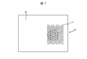
- a pressure release mechanism 40 is disposed at the bottom of each device chamber 20, which is a portion (bottom) facing the bottom of each storage battery unit 24 in main circuit storage battery box 14, as shown in FIG. .
- the pressure release mechanism 40 is disposed for each device chamber 20, and a plurality of openings 44 are formed in the bottom plate (cover) 42 at the lower part of the device chamber 20 as an element of the pressure release mechanism 40.
- the pressure release mechanism 40 can release the gas in the device chamber 20 to the outside of the device chamber 20, for example, when the pressure in the device chamber 20 exceeds the set pressure due to the abnormality of the storage battery 30.
- the released gas is at a high temperature, it blows downward from the opening 44 in the bottom plate of the equipment room 20, so even if a person is around the battery train, it does not directly hit the human body.
- the pressure release mechanism 40 is disposed at the bottom of the device chamber 20 so as to face the automatic fire extinguishing mechanism 40 with the storage battery 30 interposed therebetween, the fire extinguishing liquid discharged from the automatic fire extinguishing mechanism 40 is wastefully discharged to the outside It will not contribute to the rapid penetration of the extinguishing fluid to the bottom of the equipment room 20.
- the state associated with the abnormality of the storage battery 30 can be automatically suppressed. That is, since the main circuit storage battery box 14 is separated into a plurality of equipment rooms 20 and the automatic fire extinguishing mechanism 34 is disposed in each equipment room 20, the storage batteries 30 in the storage battery unit 24 are fired even if they fire from any of the storage batteries 30. Can be extinguished automatically and quickly. Even if the battery is ignited, the fire extinguishing agent is disposed in each of the small regions where the storage battery is disposed, so it is possible to suppress the fire only in that region, and the safety of the storage battery unit 24 and the main circuit storage battery box 14 can be enhanced.
- the inside of the main circuit storage battery box 14 is separated into a plurality of equipment rooms 20, and the pressure release mechanism 40 is disposed in each equipment room 20. Therefore, the pressure is easily increased in each equipment room 20.
- the pressure in each equipment room 20 exceeds the set pressure, the gas in each equipment room 20 can be released to the outside of each equipment room 20 quickly. For this reason, even if an ignitable gas is generated from a certain storage battery, the pressure in the small area is immediately accumulated and released from the valve (if not divided into small areas, the pressure is generated even if the gas is generated) Will not open from the valve, it will be a fire). Therefore, the safety of the storage battery unit 24 and the main circuit storage battery box 14 can be enhanced.
- the present invention is not limited to the embodiments described above, but includes various modifications.
- a pressure release mechanism for releasing the gas in the main circuit storage battery box to the outside of the main circuit storage battery box when the pressure in the main circuit storage battery box exceeds the set pressure. It can also be arranged. At this time, it is possible to minimize the influence on the surroundings and the cabin at the time of gas release.
- the above-described embodiments are described in detail to explain the present invention in an easy-to-understand manner, and are not necessarily limited to those having all the configurations described.
- SYMBOLS 10 storage battery train 12 vehicle bodies, 14 main circuit storage battery box, 20 apparatus room, 24 storage battery unit, 28 storage battery module, 30 storage battery, 34 automatic fire extinguishing mechanism, 36 extinguishing fluid storage tube, 40 pressure release mechanism, 52 main transformer, 54 Main converter, 82, 84 converter, 86, 88 inverter, 130, 196 power unit, 204, 206 cooler, 250, 252, 254, 256 main motor
Landscapes
- Engineering & Computer Science (AREA)
- Chemical & Material Sciences (AREA)
- Electrochemistry (AREA)
- General Chemical & Material Sciences (AREA)
- Chemical Kinetics & Catalysis (AREA)
- Power Engineering (AREA)
- Transportation (AREA)
- Mechanical Engineering (AREA)
- Business, Economics & Management (AREA)
- Life Sciences & Earth Sciences (AREA)
- Sustainable Development (AREA)
- Sustainable Energy (AREA)
- Emergency Management (AREA)
- Health & Medical Sciences (AREA)
- Public Health (AREA)
- Materials Engineering (AREA)
- Manufacturing & Machinery (AREA)
- Battery Mounting, Suspending (AREA)
- Charge And Discharge Circuits For Batteries Or The Like (AREA)
- Gas Exhaust Devices For Batteries (AREA)
- Electric Propulsion And Braking For Vehicles (AREA)
- Fire-Extinguishing By Fire Departments, And Fire-Extinguishing Equipment And Control Thereof (AREA)
- Protection Of Static Devices (AREA)
Abstract
本発明は、複数の機器室に分割された主回路蓄電池箱と、複数の機器室内に各々収納される複数の蓄電池ユニットと、複数の機器室に各々設置された複数の圧力開放機構と、を備え、複数の圧力開放機構が、複数の蓄電池ユニットからガスが発生した場合に各々排出する蓄電池装置に関する。 また、本発明は、複数の機器室に分割された主回路蓄電池箱と、複数の機器室内に各々収納される複数の蓄電池ユニットと、複数の機器室内に各々配置された複数の自動消火機構と、を備え、複数の自動消火機構が、複数の蓄電池ユニットが発火した場合に各々消火する蓄電池装置に関する。
Description
本発明は、蓄電池電車に搭載される蓄電池装置に関する。
蓄電池電車用動力システムとして、例えば、主変圧器の2次巻線に接続されて主電動機に駆動電力を供給する主変換回路と、主変圧器の3次巻線に接続されて補機に電力を供給する補機用変換回路を備えたものが提案されている(特許文献1参照)。また、主変圧器の3次巻線を廃止した蓄電池電車用動力システムとして、主変圧器の2次巻線に接続されて主電動機に駆動電力を供給する主変換回路であって、コンバータとインバータを含む主変換回路の直流ステージに、補機に電力を供給する静止型インバータを接続するとともに、双方向チョッパを介して蓄電池を接続したものが提案されている(特許文献2参照)。
上記特許文献には、蓄電池装置の火災対策について記載されていない。
本発明の目的は、蓄電池電車に搭載された蓄電池装置が外部短絡や圧壊などした場合、蓄電池装置の発火を防止したり、消火したりすることに関する。
本発明は、複数の機器室に分割された主回路蓄電池箱と、複数の機器室内に各々収納される複数の蓄電池ユニットと、複数の機器室に各々設置された複数の圧力開放機構と、を備え、複数の圧力開放機構が、複数の蓄電池ユニットからガスが発生した場合に各々排出する蓄電池装置に関する。
また、本発明は、複数の機器室に分割された主回路蓄電池箱と、複数の機器室内に各々収納される複数の蓄電池ユニットと、複数の機器室内に各々配置された複数の自動消火機構と、を備え、複数の自動消火機構が、複数の蓄電池ユニットが発火した場合に各々消火する蓄電池装置に関する。
本発明によれば、主回路蓄電池箱が小さな領域に区分され、それぞれに圧力開放機構が設けられ、蓄電池が収納されているため、仮にある蓄電池から発火性ガスが発生しても、小さな領域内の圧力は直ぐに高まり、発火性ガスは圧力開放機構から排出される(小さな領域に区分設置されていないと、発火性ガスが発生しても圧力が高まらず、圧力開放機構から放出されず、火災になる)。
また、本発明によれば、仮に蓄電池から発火したとしても、自動消火機構のある小さな領域のそれぞれに蓄電池が配置されているため、その領域のみで鎮火できる。他の領域に火災が広がることはない。
従って、蓄電池電車に搭載される蓄電池装置の異常に伴う状態が発生した場合、蓄電池装置の異常に伴う状態を自動的に抑制したり、回復したりすることができる。
実施例では、複数の機器室に分割された主回路蓄電池箱と、複数の機器室内に各々収納される複数の蓄電池ユニットと、複数の機器室に各々設置された複数の圧力開放機構と、を備え、複数の圧力開放機構が、複数の蓄電池ユニットからガスが発生した場合に各々排出する蓄電池装置を開示する。
また、実施例では、主回路蓄電池箱が、当該主回路蓄電池箱内のガスを外部に排出する圧力開放機構を備えることを開示する。
また、実施例では、複数の圧力開放機構が、主回路蓄電池箱の下部に設置されていることを開示する。
また、実施例では、圧力開放機構が、機器室の圧力が所定の圧力を超えた場合に、当該機器室内のガスを外部に排出する弁であることを開示する。
また、実施例では、複数の機器室に分割された主回路蓄電池箱と、複数の機器室内に各々収納される複数の蓄電池ユニットと、複数の機器室内に各々配置された複数の自動消火機構と、を備え、複数の自動消火機構は、複数の蓄電池ユニットが発火した場合に各々消火する蓄電池装置を開示する。
また、実施例では、主回路蓄電池箱が、発火した蓄電池ユニットを消火する自動消火機構を備えることを開示する。
また、実施例では、複数の自動消火機構が、同じ機器室内に収容される複数の蓄電池ユニットの上部に各々配置されることを開示する。
また、実施例では、複数の自動消火機構が、各機器室の天板に設置されていることを開示する。
また、実施例では、自動消火機構が、その周囲温度が所定温度を超えたときに、少なくともその一部が溶けて消火液を排出する消火液収納チューブであることを開示する。
また、実施例では、蓄電池ユニットが、略枠体の内部に複数の蓄電池が配置され、当該蓄電池の表面の少なくとも一部が露出していることを開示する。
以下、上記及びその他の本発明の新規な特徴と効果について図面を参酌して説明する。なお、図面は専ら発明の理解のために用いるものであり、権利範囲を限縮するものではない。
(実施例)
図1は、本実施例を示す蓄電池電車の要部正面図である。図1において、蓄電池電車10の車体12の下方には、複数の主回路蓄電池箱14が3バンク分配置されている。各主回路蓄電池箱14は、複数の蓄電池(図示せず)を収納する箱体として構成され、各蓄電池は、架線に接続された主変圧器(図示せず)からの交流電力を直流電力に変換するコンバータと、コンバータの出力による直流電力を三相交流電力に変換して主電動機(車輪駆動用誘導電動機)に出力するインバータとを有する主変換装置(いずれも図示せず)の直流回路に直流電力を供給する直流電源として構成される。
図1は、本実施例を示す蓄電池電車の要部正面図である。図1において、蓄電池電車10の車体12の下方には、複数の主回路蓄電池箱14が3バンク分配置されている。各主回路蓄電池箱14は、複数の蓄電池(図示せず)を収納する箱体として構成され、各蓄電池は、架線に接続された主変圧器(図示せず)からの交流電力を直流電力に変換するコンバータと、コンバータの出力による直流電力を三相交流電力に変換して主電動機(車輪駆動用誘導電動機)に出力するインバータとを有する主変換装置(いずれも図示せず)の直流回路に直流電力を供給する直流電源として構成される。
図2は、本実施例にかかる蓄電池電車用動力システムの全体構成図である。蓄電池電車用動力システムは、主変圧器52と、主変換装置54と、断流器箱300と、断路器400と、主回路蓄電池500及び補助電源装置600を備えている。主変圧器52は、1次巻線56と、複数の2次巻線58、60を有し、1次巻線56の一端は、真空遮断器(VCB)62と、パンタグラフ64を介して架線(AC20kV、60Hz)66に接続され、1次巻線56の他端は、車輪の接地ブラシ68を介して接地される。各2次巻線58、60は主変換装置54に接続される。
主変換装置54は、複数の接触子70、72、74、76と、抵抗78、80と、コンバータ82、84と、インバータ86、88を備えて構成される。この際、接触子70、72と抵抗78は、充電回路として構成され、接触子74、76と抵抗80は、充電回路として構成される。なお、接触子70、72、74、76は、コンバータ82、84、インバータ86、88を制御するためのコントローラ(図示せず)によって、その開閉が制御される。また、コントローラは、制御手段として、例えば、CPU(Central Processing Unit)、メモリ、入出力インタフェース等の情報処理資源を備えたコンピュータ装置で構成される。なお、コンバータ82、84の出力側には、コンデンサ220、224が接続されている。
断流器箱300は、複数の抵抗302、304と、複数の接触子306、308、310、312、314を有し、入力側(各抵抗302、304の一端側)が、各コンバータ82、84と各インバータ86、88とを結ぶ直流回路(直流ステージ)に接続され、出力側(接触子314の一端側)が、断路器400を介して主回路蓄電池500に接続される。断路器400は、スイッチ402と、スイッチ404から構成され、スイッチ402の一端側が接触子314に接続され、他端側が主回路蓄電池500の高電位側に接続され、スイッチ404の一端側がコンバータ84の低電位側に接続され、他端側が主回路蓄電池500の低電位側に接続されている。
主回路蓄電池500は、複数の接触子502、504、506、508、510、512と、複数の蓄電池514、516、518から構成される。補助電源装置600は、補機(空調装置、照明装置)に電力を供給するための補助電源装置として構成され、例えば、入力された直流電圧を半導体素子でスイッチングし、スイッチングされた電圧をコンデンサ等で平滑化して交流電圧として出力する静止形インバータで構成される。
ここで、架線走行(力行)時には、インバータ消費電力と補機消費電力を架線66から主変圧器52を介して主変換装置54に取り込み、各インバータ86、88により各主電動機250、252、254、256を駆動し、各コンバータ82、84の出力電力を、補助電源装置600を介して補機に供給する。この際、コントローラにより、各インバータ86、88と各コンバータ82、84の電力変換動作が実行され、各コンバータ82、84の出力電力で主回路蓄電池500を充電することができる。
架線走行(回生)時には、各主電動機250、252、254、256からの回生電力(回生エネルギー)を、各インバータ86、88を介して主変換装置54に取り込み、取り込んだ回生電力で主回路蓄電池500を充電すると共に、取り込んだ回生電力を、補助電源装置600を介して補機に供給する。なお、充電完了後、回生電力は架線に回生される。
架線走行(惰行・停車)時には、補機消費電力と蓄電池充電電力を架線66から主変圧器52を介して主変換装置54に取り込み、各コンバータ82、84の出力電力で主回路蓄電池500を充電し、各コンバータ82、84の出力電力を、補助電源装置600を介して補機に供給する。充電完了後、各コンバータ82、84の運転は停止され、主回路蓄電池500から補助電源装置600を介して補機に給電される。
蓄電池走行(力行)時には、各コンバータ82、84の運転が停止され、主回路蓄電池500からの電力を主変換装置54に取り込み、各インバータ86、88により各主電動機250~256を駆動し、主回路蓄電池500からの電力を、補助電源装置600を介して補機に供給する。この際、コントローラにより、各インバータ86、88の電力変換動作が実行され、各コンバータ82、84の電力変換動作が停止される。
蓄電池走行(回生)時には、各コンバータ82、84の運転が停止され、各主電動機250~256からの回生電力(回生エネルギー)を、各インバータ86、88を介して主変換装置54に取り込み、取り込んだ回生電力で主回路蓄電池500を充電すると共に、取り込んだ回生電力を、補助電源装置600を介して補機に供給する。
蓄電池走行(惰行・停車)時には、各コンバータ82、84、各インバータ86、88の運転が停止され、主回路蓄電池500からの電力を、補助電源装置600を介して補機に供給する。
図3は、本実施例にかかる主回路蓄電池箱の斜視図である。図3において、主回路蓄電池箱14は、蓄電池電車用蓄電池装置の主構成要素して、金属製の箱体16で構成され、箱体16内は、複数の仕切板18によって、複数(6個)の機器室20と複数の備品室22に分離されている。各機器室20内には、図4に示すように、蓄電池ユニット24が収納される。各備品室22には、コントローラや接触子などの備品(いずれも図示せず)が収納される。
蓄電池ユニット24は、複数の金属フレーム26等によって、略直方体形状の枠体として構成される。蓄電池ユニット24内には、図5に示すように、蓄電池モジュール28が12個収納される。蓄電池モジュール28は、蓄電池(セル)30を6個収納する蓄電池収納ケースとして構成される。蓄電池モジュール28も、略直方体形状の枠体として構成される。この際、6個の蓄電池30が収納された蓄電池モジュール28が12個蓄電池ユニット24に収納されるので、蓄電池ユニット24には、全体として72個の蓄電池30が収納される。蓄電池ユニット24及び蓄電池モジュール28が枠体として構成されているため、収納された蓄電池30の長手表面は露出している。また、蓄電池ユニット24に収納された蓄電池モジュール28は、導体バー32を介して互いに直列に接続され(図4参照)、各蓄電池30は、蓄電池モジュール28内で互いに直列に接続される。即ち、蓄電池ユニット24内の72個の蓄電池30は、互いに直列に接続される。蓄電池30としては、例えば、リチウムイオン電池を用いることができる。
各機器室20に収納される蓄電池ユニット24の上部(天板)には、図6に示すように放充電により発熱する蓄電池30を冷却するための複数の冷却用ファン38と、自動消火機構34が配置されている。自動消火機構34は、消火液収納容器又は消火液収納手段としての消火液収納チューブ36を有し、消火液収納チューブ36内には、消火液(図示せず)が収納されている。蓄電池ユニット24の上部に自動消火機構34が配置されているため、蓄電池30が発火すると、上昇気流により、自動消火機構34の周囲温度は直ちに上昇する。消火液収納チューブ36は、周囲温度が設定温度を超えたときに、少なくともその一部が溶けて、消火液を排出する材質のもので構成される。この際、例えば、蓄電池30が短絡したり、蓄電池30が外部からの圧力によってつぶれたりして、蓄電池30から発火し、周囲温度が設定温度を超えた場合、消火液収納チューブ36の一部が溶けて、消火液が蓄電池ユニット24内に排出される。自動消火機構34の下部に蓄電池ユニット24が配置されているため、排出された消火液は、蓄電池ユニット24の下部まで自然に浸透し、発火した蓄電池30を覆う。このため、いずれかの蓄電池30から発火しても、蓄電池ユニット24内の蓄電池30を自動的に且つ迅速に消火することができ、蓄電池ユニット24及び主回路蓄電池箱14の安全性を高めることができる。また、消火液収納チューブ36としては、周囲温度に基づいて消火液を放出する構成とすることができる。例えば、消火液収納チューブ36に、周囲温度に応じて開閉する弁を設け、消火液収納チューブ36内の消火液の温度が設定温度を超えた場合、弁を開いて消火液を放出する。さらに、消火液収納チューブ36の代わりに、周囲温度を検知する温度センサーの検出温度が設定温度を超えたときに、消火液を放出する消火器を用いることもできる。また、消火液の代わりに、消火粉末や消火ガスを用いた消火器でもよい。
一方、主回路蓄電池箱14のうち各蓄電池ユニット24の底部に対向した部位(底部)であって、各機器室20の底部には、図7に示すように、圧力開放機構40が配置される。圧力開放機構40は、機器室20毎に配置されており、機器室20の下部の底板(カバー)42には、圧力開放機構40の一要素として複数の開口44が形成されている。圧力開放機構40は、例えば、蓄電池30の異常に伴って、機器室20内の圧力が設定圧力を超えたときに、機器室20内のガスを機器室20外に放出することができる。放出されたガスは高温であるが、機器室20の底板にある開口44から下方に向けて噴出するため、仮に蓄電池電車の周囲に人がいたとしても、人体に直接当ることは無い。また、圧力開放機構40は、蓄電池30を挟んで自動消火機構40と対向するように機器室20の底部に配置されているため、自動消火機構40から排出された消火液が無駄に外部に放出されることはなく、消火液が機器室20の底部まで速やかに浸透することに寄与する。
本実施例によれば、蓄電池電車10に搭載される蓄電池30の異常に伴う状態が発生した場合、蓄電池30の異常に伴う状態を自動的に抑制することができる。即ち、主回路蓄電池箱14内を複数の機器室20に分離し、各機器室20に自動消火機構34を配置したので、いずれかの蓄電池30から発火しても、蓄電池ユニット24内の蓄電池30を自動的に且つ迅速に消火することができる。仮に発火したとしても、蓄電池が配置されている小さな領域のそれぞれに消火剤が配置されているため、その領域のみで鎮火でき、蓄電池ユニット24及び主回路蓄電池箱14の安全性を高めることができる。また、必要な個所のみ消火することにより、消火剤を浴びて使用できなくなる蓄電池ユニット24を最小化でき、消火液(消火剤)の量も削減することができる。
また、本実施例によれば、主回路蓄電池箱14内を複数の機器室20に分離し、各機器室20に圧力開放機構40を配置したので、各機器室20で圧力が上昇しやすくなり、各機器室20内の圧力が設定圧力を超えたときには、各機器室20内のガスを各機器室20外に迅速に放出することができる。このため、仮に、ある蓄電池から発火性のガスが発生しても、小さな領域内の圧力は直ぐにたまり、弁から解放される(小さな領域に区分設置されていないと、ガスが発生しても圧力が高まらず、弁から開放されず、火災になる)。従って、蓄電池ユニット24及び主回路蓄電池箱14の安全性を高めることができる。
なお、本発明は上記した実施例に限定されるものではなく、様々な変形例が含まれる。例えば、主回路蓄電池箱14の底部のいずれかに、主回路蓄電池箱内の圧力が設定圧力を超えたときに、主回路蓄電池箱内のガスを主回路蓄電池箱外に放出する圧力開放機構を配置することもできる。この際、ガス放出時の周囲や客室への影響を最小化することができる。上記した実施例は本発明を分かりやすく説明するために詳細に説明したものであり、必ずしも説明した全ての構成を備えるものに限定されるものではない。また、実施例の構成の一部について、他の構成の追加・削除・置換をすることが可能である。
10 蓄電池電車、12 車体、14 主回路蓄電池箱、20 機器室、24 蓄電池ユニット、28 蓄電池モジュール、30 蓄電池、34 自動消火機構、36 消火液収納チューブ、40 圧力開放機構、52 主変圧器、54 主変換装置、82、84 コンバータ、86、88 インバータ、130、196 パワーユニット、204、206 冷却器、250、252、254、256 主電動機
Claims (12)
- 蓄電池電車に搭載される蓄電池装置であって、
複数の機器室に分割された主回路蓄電池箱と、
前記複数の機器室内に各々収納される複数の蓄電池ユニットと、
前記複数の機器室内に各々配置された複数の自動消火機構と、を備え、
前記複数の自動消火機構は、前記複数の蓄電池ユニットが発火した場合に各々消火することを特徴とする蓄電池装置。 - 請求項1に記載の蓄電池装置において、
前記複数の自動消火機構が、同じ機器室内に収容される複数の蓄電池ユニットの上部に各々配置されることを特徴とする蓄電池装置。 - 請求項2に記載の蓄電池装置において、
前記複数の自動消火機構が、各機器室の天板に設置されていることを特徴とする蓄電池装置。 - 請求項1~3のいずれかに記載の蓄電池装置において、
前記自動消火機構が、その周囲温度が所定温度を超えたときに、少なくともその一部が溶けて消火液を排出する消火液収納チューブであることを特徴とする蓄電池装置。 - 請求項1~4のいずれかに記載の蓄電池装置において、
前記蓄電池ユニットが、略枠体の内部に複数の蓄電池が配置され、当該蓄電池の表面の少なくとも一部が露出していることを特徴とする蓄電池装置。 - 請求項1~5のいずれかに記載の蓄電池装置において、
前記主回路蓄電池箱が、当該主回路蓄電池箱内のガスを外部に排出する圧力開放機構を備えることを特徴とする蓄電池装置。 - 蓄電池電車に搭載される蓄電池装置であって、
複数の機器室に分割された主回路蓄電池箱と、
前記複数の機器室内に各々収納される複数の蓄電池ユニットと、
前記複数の機器室に各々設置された複数の圧力開放機構と、を備え、
前記複数の圧力開放機構は、前記複数の蓄電池ユニットからガスが発生した場合に各々排出することを特徴とする蓄電池装置。 - 請求項7に記載の蓄電池装置において、
前記複数の圧力開放機構が、前記主回路蓄電池箱の下部に設置されていることを特徴とする蓄電池装置。 - 請求項7~8のいずれかに記載の蓄電池装置において、
前記圧力開放機構が、前記機器室の圧力が所定の圧力を超えた場合に、当該機器室内のガスを外部に排出する弁であることを特徴とする蓄電池装置。 - 請求項7~9のいずれかに記載の蓄電池装置において、
前記蓄電池ユニットが、略枠体の内部に複数の蓄電池が配置され、当該蓄電池の表面の少なくとも一部が露出していることを特徴とする蓄電池装置。 - 請求項7~10のいずれかに記載の蓄電池装置において、
前記主回路蓄電池箱が、発火した前記蓄電池ユニットを消火する自動消火機構を備えることを特徴とする蓄電池装置。 - 請求項1~11のいずれかに記載の蓄電池装置を搭載した蓄電池電車。
Priority Applications (2)
| Application Number | Priority Date | Filing Date | Title |
|---|---|---|---|
| JP2018546283A JP6738905B2 (ja) | 2016-10-18 | 2017-10-12 | 蓄電池電車用蓄電池装置及び蓄電池電車 |
| EP17862233.8A EP3530324A4 (en) | 2016-10-18 | 2017-10-12 | STORAGE BATTERY DEVICE FOR ELECTRIC AUTORAIL WITH STORAGE BATTERY, AND ELECTRIC AUTORAIL WITH STORAGE BATTERY |
Applications Claiming Priority (2)
| Application Number | Priority Date | Filing Date | Title |
|---|---|---|---|
| JP2016204432 | 2016-10-18 | ||
| JP2016-204432 | 2016-10-18 |
Publications (1)
| Publication Number | Publication Date |
|---|---|
| WO2018074325A1 true WO2018074325A1 (ja) | 2018-04-26 |
Family
ID=62019112
Family Applications (1)
| Application Number | Title | Priority Date | Filing Date |
|---|---|---|---|
| PCT/JP2017/037051 Ceased WO2018074325A1 (ja) | 2016-10-18 | 2017-10-12 | 蓄電池電車用蓄電池装置及び蓄電池電車 |
Country Status (3)
| Country | Link |
|---|---|
| EP (1) | EP3530324A4 (ja) |
| JP (1) | JP6738905B2 (ja) |
| WO (1) | WO2018074325A1 (ja) |
Cited By (8)
| Publication number | Priority date | Publication date | Assignee | Title |
|---|---|---|---|---|
| CN109037803A (zh) * | 2018-07-28 | 2018-12-18 | 杭州林迪德瑞科技有限公司 | 蓄电池集中充电装置及方法 |
| CN109560588A (zh) * | 2018-12-25 | 2019-04-02 | 中建深圳装饰有限公司 | 一种移动充电电箱及其使用方法 |
| WO2020135348A1 (zh) * | 2018-12-28 | 2020-07-02 | 宁德时代新能源科技股份有限公司 | 一种电池包的喷淋系统、电池包及车辆 |
| CN111430596A (zh) * | 2019-01-09 | 2020-07-17 | 比亚迪股份有限公司 | 动力电池包及电动车 |
| CN113228396A (zh) * | 2018-10-15 | 2021-08-06 | 电力系统股份有限公司 | 通过冷却剂分散进行电池热管理 |
| WO2022024515A1 (ja) * | 2020-07-28 | 2022-02-03 | 日立建機株式会社 | ドライブシステム |
| JPWO2022092159A1 (ja) * | 2020-11-02 | 2022-05-05 | ||
| KR20240022670A (ko) * | 2022-08-12 | 2024-02-20 | 공오일컴퍼니 주식회사 | 휴대용 전기자동차 충전장치 |
Families Citing this family (2)
| Publication number | Priority date | Publication date | Assignee | Title |
|---|---|---|---|---|
| GB2597996B (en) * | 2020-08-14 | 2023-05-03 | Hitachi Rail Ltd | Railway vehicle including an energy storage system |
| GB2629580B (en) * | 2023-05-02 | 2026-03-18 | Hitachi Rail Ltd | Combined switching system for an electrically powered railway vehicle |
Citations (9)
| Publication number | Priority date | Publication date | Assignee | Title |
|---|---|---|---|---|
| JP2012129138A (ja) * | 2010-12-17 | 2012-07-05 | Hitachi Ltd | 鉄道車両用電池ユニット |
| JP2013196907A (ja) * | 2012-03-19 | 2013-09-30 | Toyota Motor Corp | 蓄電装置 |
| WO2014034057A1 (ja) * | 2012-08-27 | 2014-03-06 | 三洋電機株式会社 | バッテリシステム及びバッテリシステムを備える電動車両並びに蓄電装置 |
| JP2014049226A (ja) * | 2012-08-30 | 2014-03-17 | Shin Kobe Electric Mach Co Ltd | 二次電池モジュール |
| JP2014064397A (ja) | 2012-09-21 | 2014-04-10 | Kyushu Railway Co | 電気車用電源システム及び電力供給制御方法 |
| JP2014064398A (ja) | 2012-09-21 | 2014-04-10 | Kyushu Railway Co | 電気車用電源システム及び電力供給制御方法 |
| JP2014082108A (ja) * | 2012-10-17 | 2014-05-08 | Hochiki Corp | 蓄電装置 |
| JP2014235845A (ja) * | 2013-05-31 | 2014-12-15 | 株式会社豊田自動織機 | 蓄電モジュール |
| JP2016150199A (ja) * | 2015-02-19 | 2016-08-22 | 株式会社 セーフティー1 | 自動消火装置 |
Family Cites Families (6)
| Publication number | Priority date | Publication date | Assignee | Title |
|---|---|---|---|---|
| JP2007027011A (ja) * | 2005-07-20 | 2007-02-01 | Sanyo Electric Co Ltd | 電源装置 |
| JP2010097836A (ja) * | 2008-10-17 | 2010-04-30 | Panasonic Corp | 電池パック、それを電源として用いた電子機器、及び電池パック用ケース |
| KR101424704B1 (ko) * | 2011-09-08 | 2014-07-31 | 주식회사 엘지화학 | 배터리 팩 화재진압 장치 |
| WO2015045195A1 (ja) * | 2013-09-27 | 2015-04-02 | 株式会社ニチボウ | 自動消火具 |
| WO2015120742A1 (zh) * | 2014-02-13 | 2015-08-20 | 浙江吉利汽车研究院有限公司 | 一种汽车电池的热管理与自动灭火系统 |
| JP6385766B2 (ja) * | 2014-09-17 | 2018-09-05 | 株式会社東芝 | 車両用蓄電池装置 |
-
2017
- 2017-10-12 EP EP17862233.8A patent/EP3530324A4/en active Pending
- 2017-10-12 WO PCT/JP2017/037051 patent/WO2018074325A1/ja not_active Ceased
- 2017-10-12 JP JP2018546283A patent/JP6738905B2/ja active Active
Patent Citations (9)
| Publication number | Priority date | Publication date | Assignee | Title |
|---|---|---|---|---|
| JP2012129138A (ja) * | 2010-12-17 | 2012-07-05 | Hitachi Ltd | 鉄道車両用電池ユニット |
| JP2013196907A (ja) * | 2012-03-19 | 2013-09-30 | Toyota Motor Corp | 蓄電装置 |
| WO2014034057A1 (ja) * | 2012-08-27 | 2014-03-06 | 三洋電機株式会社 | バッテリシステム及びバッテリシステムを備える電動車両並びに蓄電装置 |
| JP2014049226A (ja) * | 2012-08-30 | 2014-03-17 | Shin Kobe Electric Mach Co Ltd | 二次電池モジュール |
| JP2014064397A (ja) | 2012-09-21 | 2014-04-10 | Kyushu Railway Co | 電気車用電源システム及び電力供給制御方法 |
| JP2014064398A (ja) | 2012-09-21 | 2014-04-10 | Kyushu Railway Co | 電気車用電源システム及び電力供給制御方法 |
| JP2014082108A (ja) * | 2012-10-17 | 2014-05-08 | Hochiki Corp | 蓄電装置 |
| JP2014235845A (ja) * | 2013-05-31 | 2014-12-15 | 株式会社豊田自動織機 | 蓄電モジュール |
| JP2016150199A (ja) * | 2015-02-19 | 2016-08-22 | 株式会社 セーフティー1 | 自動消火装置 |
Non-Patent Citations (1)
| Title |
|---|
| See also references of EP3530324A4 |
Cited By (15)
| Publication number | Priority date | Publication date | Assignee | Title |
|---|---|---|---|---|
| CN109037803B (zh) * | 2018-07-28 | 2020-06-26 | 王玲萍 | 蓄电池集中充电装置及方法 |
| CN109037803A (zh) * | 2018-07-28 | 2018-12-18 | 杭州林迪德瑞科技有限公司 | 蓄电池集中充电装置及方法 |
| CN113228396A (zh) * | 2018-10-15 | 2021-08-06 | 电力系统股份有限公司 | 通过冷却剂分散进行电池热管理 |
| JP2022508811A (ja) * | 2018-10-15 | 2022-01-19 | エレクトリック パワー システムズ, インコーポレイテッド | 冷却剤分散によるバッテリの熱的管理 |
| CN109560588A (zh) * | 2018-12-25 | 2019-04-02 | 中建深圳装饰有限公司 | 一种移动充电电箱及其使用方法 |
| WO2020135348A1 (zh) * | 2018-12-28 | 2020-07-02 | 宁德时代新能源科技股份有限公司 | 一种电池包的喷淋系统、电池包及车辆 |
| CN111430596A (zh) * | 2019-01-09 | 2020-07-17 | 比亚迪股份有限公司 | 动力电池包及电动车 |
| CN111430596B (zh) * | 2019-01-09 | 2022-06-10 | 比亚迪股份有限公司 | 动力电池包及电动车 |
| WO2022024515A1 (ja) * | 2020-07-28 | 2022-02-03 | 日立建機株式会社 | ドライブシステム |
| JP2022024822A (ja) * | 2020-07-28 | 2022-02-09 | 日立建機株式会社 | ドライブシステム |
| US12224650B2 (en) | 2020-07-28 | 2025-02-11 | Hitachi Construction Machinery Co., Ltd. | Drive system having an induction generator with a main winding and auxiliary winding |
| JPWO2022092159A1 (ja) * | 2020-11-02 | 2022-05-05 | ||
| JP7848691B2 (ja) | 2020-11-02 | 2026-04-21 | Toppanホールディングス株式会社 | 筒状消火体及びバッテリーパック |
| KR20240022670A (ko) * | 2022-08-12 | 2024-02-20 | 공오일컴퍼니 주식회사 | 휴대용 전기자동차 충전장치 |
| KR102644836B1 (ko) * | 2022-08-12 | 2024-03-07 | 공오일컴퍼니 주식회사 | 휴대용 전기자동차 충전장치 |
Also Published As
| Publication number | Publication date |
|---|---|
| EP3530324A1 (en) | 2019-08-28 |
| JPWO2018074325A1 (ja) | 2019-10-03 |
| EP3530324A4 (en) | 2020-06-10 |
| JP6738905B2 (ja) | 2020-08-12 |
Similar Documents
| Publication | Publication Date | Title |
|---|---|---|
| JP6738905B2 (ja) | 蓄電池電車用蓄電池装置及び蓄電池電車 | |
| US10658714B2 (en) | Thermal event detection and management system for an electric vehicle | |
| US10622176B2 (en) | High voltage electric line cutter device | |
| JP6549306B2 (ja) | 車両 | |
| JP5666635B2 (ja) | 車両用電池パック | |
| KR20120136830A (ko) | 고전압 배터리팩의 화재진압 장치 및 방법 | |
| CN107406002B (zh) | 车载用蓄电装置 | |
| US20150211534A1 (en) | Battery-operated blower filter system for use in potentially explosive areas | |
| JP2008253084A (ja) | ハイブリッド電源システム | |
| JP2000134701A (ja) | 鉄道車両用電力変換装置 | |
| KR20180113800A (ko) | 이동형 에너지저장장치 | |
| KR20160082102A (ko) | 댐퍼가 구비된 에너지 저장장치용 공조장치 및 이를 포함하는 에너지 저장장치 | |
| KR101968036B1 (ko) | 배터리를 제조하기 위한 방법, 배터리 및 자동차 | |
| JP2017011966A (ja) | ハイブリッド鉄道車両の充電制御装置 | |
| JP2020092552A (ja) | 電源システム | |
| JP5631247B2 (ja) | 車両用電源装置 | |
| JP2022054052A (ja) | 直流回路開閉装置 | |
| KR102790573B1 (ko) | 전기자동차의 리튬배터리 화재 비상 대응 시스템 | |
| JP3576976B2 (ja) | 高圧電池の冷却装置 | |
| JP3895699B2 (ja) | 車両用の放電装置 | |
| CN211166399U (zh) | 一种纯电动客车的整车布置结构 | |
| JP2017045700A (ja) | バッテリー装置及び鉄道車両 | |
| JP7647273B2 (ja) | 車載ユニットの配置構造 | |
| CN222638186U (zh) | 一种储能柜 | |
| KR20240080362A (ko) | 전기자동차의 화재 진압 장치 |
Legal Events
| Date | Code | Title | Description |
|---|---|---|---|
| 121 | Ep: the epo has been informed by wipo that ep was designated in this application |
Ref document number: 17862233 Country of ref document: EP Kind code of ref document: A1 |
|
| ENP | Entry into the national phase |
Ref document number: 2018546283 Country of ref document: JP Kind code of ref document: A |
|
| NENP | Non-entry into the national phase |
Ref country code: DE |
|
| ENP | Entry into the national phase |
Ref document number: 2017862233 Country of ref document: EP Effective date: 20190520 |