WO2018074423A1 - ファン動翼及びその製造方法 - Google Patents
ファン動翼及びその製造方法 Download PDFInfo
- Publication number
- WO2018074423A1 WO2018074423A1 PCT/JP2017/037393 JP2017037393W WO2018074423A1 WO 2018074423 A1 WO2018074423 A1 WO 2018074423A1 JP 2017037393 W JP2017037393 W JP 2017037393W WO 2018074423 A1 WO2018074423 A1 WO 2018074423A1
- Authority
- WO
- WIPO (PCT)
- Prior art keywords
- rotor blade
- fan rotor
- metal core
- thermoplastic resin
- hollow structure
- Prior art date
- Legal status (The legal status is an assumption and is not a legal conclusion. Google has not performed a legal analysis and makes no representation as to the accuracy of the status listed.)
- Ceased
Links
Images


Classifications
-
- F—MECHANICAL ENGINEERING; LIGHTING; HEATING; WEAPONS; BLASTING
- F04—POSITIVE - DISPLACEMENT MACHINES FOR LIQUIDS; PUMPS FOR LIQUIDS OR ELASTIC FLUIDS
- F04D—NON-POSITIVE-DISPLACEMENT PUMPS
- F04D29/00—Details, component parts, or accessories
- F04D29/26—Rotors specially for elastic fluids
- F04D29/32—Rotors specially for elastic fluids for axial flow pumps
- F04D29/38—Blades
- F04D29/384—Blades characterised by form
-
- F—MECHANICAL ENGINEERING; LIGHTING; HEATING; WEAPONS; BLASTING
- F04—POSITIVE - DISPLACEMENT MACHINES FOR LIQUIDS; PUMPS FOR LIQUIDS OR ELASTIC FLUIDS
- F04D—NON-POSITIVE-DISPLACEMENT PUMPS
- F04D29/00—Details, component parts, or accessories
- F04D29/26—Rotors specially for elastic fluids
- F04D29/32—Rotors specially for elastic fluids for axial flow pumps
- F04D29/38—Blades
- F04D29/388—Blades characterised by construction
-
- B—PERFORMING OPERATIONS; TRANSPORTING
- B29—WORKING OF PLASTICS; WORKING OF SUBSTANCES IN A PLASTIC STATE IN GENERAL
- B29C—SHAPING OR JOINING OF PLASTICS; SHAPING OF MATERIAL IN A PLASTIC STATE, NOT OTHERWISE PROVIDED FOR; AFTER-TREATMENT OF THE SHAPED PRODUCTS, e.g. REPAIRING
- B29C43/00—Compression moulding, i.e. applying external pressure to flow the moulding material; Apparatus therefor
- B29C43/02—Compression moulding, i.e. applying external pressure to flow the moulding material; Apparatus therefor of articles of definite length, i.e. discrete articles
- B29C43/20—Making multilayered or multicoloured articles
-
- B—PERFORMING OPERATIONS; TRANSPORTING
- B29—WORKING OF PLASTICS; WORKING OF SUBSTANCES IN A PLASTIC STATE IN GENERAL
- B29C—SHAPING OR JOINING OF PLASTICS; SHAPING OF MATERIAL IN A PLASTIC STATE, NOT OTHERWISE PROVIDED FOR; AFTER-TREATMENT OF THE SHAPED PRODUCTS, e.g. REPAIRING
- B29C70/00—Shaping composites, i.e. plastics material comprising reinforcements, fillers or preformed parts, e.g. inserts
- B29C70/68—Shaping composites, i.e. plastics material comprising reinforcements, fillers or preformed parts, e.g. inserts by incorporating or moulding on preformed parts, e.g. inserts or layers, e.g. foam blocks
- B29C70/86—Incorporated in coherent impregnated reinforcing layers, e.g. by winding
-
- B—PERFORMING OPERATIONS; TRANSPORTING
- B29—WORKING OF PLASTICS; WORKING OF SUBSTANCES IN A PLASTIC STATE IN GENERAL
- B29D—PRODUCING PARTICULAR ARTICLES FROM PLASTICS OR FROM SUBSTANCES IN A PLASTIC STATE
- B29D24/00—Producing articles with hollow walls
- B29D24/002—Producing articles with hollow walls formed with structures, e.g. cores placed between two plates or sheets, e.g. partially filled
- B29D24/005—Producing articles with hollow walls formed with structures, e.g. cores placed between two plates or sheets, e.g. partially filled the structure having joined ribs, e.g. honeycomb
-
- B—PERFORMING OPERATIONS; TRANSPORTING
- B29—WORKING OF PLASTICS; WORKING OF SUBSTANCES IN A PLASTIC STATE IN GENERAL
- B29D—PRODUCING PARTICULAR ARTICLES FROM PLASTICS OR FROM SUBSTANCES IN A PLASTIC STATE
- B29D99/00—Subject matter not provided for in other groups of this subclass
- B29D99/0025—Producing blades or the like, e.g. blades for turbines, propellers, or wings
-
- B—PERFORMING OPERATIONS; TRANSPORTING
- B64—AIRCRAFT; AVIATION; COSMONAUTICS
- B64C—AEROPLANES; HELICOPTERS
- B64C1/00—Fuselages; Constructional features common to fuselages, wings, stabilising surfaces or the like
-
- F—MECHANICAL ENGINEERING; LIGHTING; HEATING; WEAPONS; BLASTING
- F01—MACHINES OR ENGINES IN GENERAL; ENGINE PLANTS IN GENERAL; STEAM ENGINES
- F01D—NON-POSITIVE DISPLACEMENT MACHINES OR ENGINES, e.g. STEAM TURBINES
- F01D5/00—Blades; Blade-carrying members; Heating, heat-insulating, cooling or antivibration means on the blades or the members
- F01D5/12—Blades
- F01D5/28—Selecting particular materials; Particular measures relating thereto; Measures against erosion or corrosion
- F01D5/282—Selecting composite materials, e.g. blades with reinforcing filaments
-
- F—MECHANICAL ENGINEERING; LIGHTING; HEATING; WEAPONS; BLASTING
- F02—COMBUSTION ENGINES; HOT-GAS OR COMBUSTION-PRODUCT ENGINE PLANTS
- F02C—GAS-TURBINE PLANTS; AIR INTAKES FOR JET-PROPULSION PLANTS; CONTROLLING FUEL SUPPLY IN AIR-BREATHING JET-PROPULSION PLANTS
- F02C7/00—Features, components parts, details or accessories, not provided for in, or of interest apart form groups F02C1/00 - F02C6/00; Air intakes for jet-propulsion plants
-
- F—MECHANICAL ENGINEERING; LIGHTING; HEATING; WEAPONS; BLASTING
- F04—POSITIVE - DISPLACEMENT MACHINES FOR LIQUIDS; PUMPS FOR LIQUIDS OR ELASTIC FLUIDS
- F04D—NON-POSITIVE-DISPLACEMENT PUMPS
- F04D29/00—Details, component parts, or accessories
- F04D29/02—Selection of particular materials
- F04D29/023—Selection of particular materials especially adapted for elastic fluid pumps
-
- F—MECHANICAL ENGINEERING; LIGHTING; HEATING; WEAPONS; BLASTING
- F04—POSITIVE - DISPLACEMENT MACHINES FOR LIQUIDS; PUMPS FOR LIQUIDS OR ELASTIC FLUIDS
- F04D—NON-POSITIVE-DISPLACEMENT PUMPS
- F04D29/00—Details, component parts, or accessories
- F04D29/26—Rotors specially for elastic fluids
- F04D29/32—Rotors specially for elastic fluids for axial flow pumps
- F04D29/38—Blades
-
- B—PERFORMING OPERATIONS; TRANSPORTING
- B29—WORKING OF PLASTICS; WORKING OF SUBSTANCES IN A PLASTIC STATE IN GENERAL
- B29K—INDEXING SCHEME ASSOCIATED WITH SUBCLASSES B29B, B29C OR B29D, RELATING TO MOULDING MATERIALS OR TO MATERIALS FOR MOULDS, REINFORCEMENTS, FILLERS OR PREFORMED PARTS, e.g. INSERTS
- B29K2105/00—Condition, form or state of moulded material or of the material to be shaped
- B29K2105/04—Condition, form or state of moulded material or of the material to be shaped cellular or porous
-
- B—PERFORMING OPERATIONS; TRANSPORTING
- B29—WORKING OF PLASTICS; WORKING OF SUBSTANCES IN A PLASTIC STATE IN GENERAL
- B29K—INDEXING SCHEME ASSOCIATED WITH SUBCLASSES B29B, B29C OR B29D, RELATING TO MOULDING MATERIALS OR TO MATERIALS FOR MOULDS, REINFORCEMENTS, FILLERS OR PREFORMED PARTS, e.g. INSERTS
- B29K2705/00—Use of metals, their alloys or their compounds, for preformed parts, e.g. for inserts
-
- F—MECHANICAL ENGINEERING; LIGHTING; HEATING; WEAPONS; BLASTING
- F01—MACHINES OR ENGINES IN GENERAL; ENGINE PLANTS IN GENERAL; STEAM ENGINES
- F01D—NON-POSITIVE DISPLACEMENT MACHINES OR ENGINES, e.g. STEAM TURBINES
- F01D5/00—Blades; Blade-carrying members; Heating, heat-insulating, cooling or antivibration means on the blades or the members
- F01D5/12—Blades
- F01D5/14—Form or construction
- F01D5/147—Construction, i.e. structural features, e.g. of weight-saving hollow blades
-
- F—MECHANICAL ENGINEERING; LIGHTING; HEATING; WEAPONS; BLASTING
- F05—INDEXING SCHEMES RELATING TO ENGINES OR PUMPS IN VARIOUS SUBCLASSES OF CLASSES F01-F04
- F05D—INDEXING SCHEME FOR ASPECTS RELATING TO NON-POSITIVE-DISPLACEMENT MACHINES OR ENGINES, GAS-TURBINES OR JET-PROPULSION PLANTS
- F05D2220/00—Application
- F05D2220/30—Application in turbines
- F05D2220/36—Application in turbines specially adapted for the fan of turbofan engines
-
- F—MECHANICAL ENGINEERING; LIGHTING; HEATING; WEAPONS; BLASTING
- F05—INDEXING SCHEMES RELATING TO ENGINES OR PUMPS IN VARIOUS SUBCLASSES OF CLASSES F01-F04
- F05D—INDEXING SCHEME FOR ASPECTS RELATING TO NON-POSITIVE-DISPLACEMENT MACHINES OR ENGINES, GAS-TURBINES OR JET-PROPULSION PLANTS
- F05D2250/00—Geometry
- F05D2250/20—Three-dimensional
- F05D2250/28—Three-dimensional patterned
- F05D2250/283—Three-dimensional patterned honeycomb
-
- F—MECHANICAL ENGINEERING; LIGHTING; HEATING; WEAPONS; BLASTING
- F05—INDEXING SCHEMES RELATING TO ENGINES OR PUMPS IN VARIOUS SUBCLASSES OF CLASSES F01-F04
- F05D—INDEXING SCHEME FOR ASPECTS RELATING TO NON-POSITIVE-DISPLACEMENT MACHINES OR ENGINES, GAS-TURBINES OR JET-PROPULSION PLANTS
- F05D2300/00—Materials; Properties thereof
- F05D2300/10—Metals, alloys or intermetallic compounds
-
- F—MECHANICAL ENGINEERING; LIGHTING; HEATING; WEAPONS; BLASTING
- F05—INDEXING SCHEMES RELATING TO ENGINES OR PUMPS IN VARIOUS SUBCLASSES OF CLASSES F01-F04
- F05D—INDEXING SCHEME FOR ASPECTS RELATING TO NON-POSITIVE-DISPLACEMENT MACHINES OR ENGINES, GAS-TURBINES OR JET-PROPULSION PLANTS
- F05D2300/00—Materials; Properties thereof
- F05D2300/60—Properties or characteristics given to material by treatment or manufacturing
- F05D2300/603—Composites; e.g. fibre-reinforced
-
- F—MECHANICAL ENGINEERING; LIGHTING; HEATING; WEAPONS; BLASTING
- F05—INDEXING SCHEMES RELATING TO ENGINES OR PUMPS IN VARIOUS SUBCLASSES OF CLASSES F01-F04
- F05D—INDEXING SCHEME FOR ASPECTS RELATING TO NON-POSITIVE-DISPLACEMENT MACHINES OR ENGINES, GAS-TURBINES OR JET-PROPULSION PLANTS
- F05D2300/00—Materials; Properties thereof
- F05D2300/60—Properties or characteristics given to material by treatment or manufacturing
- F05D2300/612—Foam
-
- Y—GENERAL TAGGING OF NEW TECHNOLOGICAL DEVELOPMENTS; GENERAL TAGGING OF CROSS-SECTIONAL TECHNOLOGIES SPANNING OVER SEVERAL SECTIONS OF THE IPC; TECHNICAL SUBJECTS COVERED BY FORMER USPC CROSS-REFERENCE ART COLLECTIONS [XRACs] AND DIGESTS
- Y02—TECHNOLOGIES OR APPLICATIONS FOR MITIGATION OR ADAPTATION AGAINST CLIMATE CHANGE
- Y02T—CLIMATE CHANGE MITIGATION TECHNOLOGIES RELATED TO TRANSPORTATION
- Y02T50/00—Aeronautics or air transport
- Y02T50/40—Weight reduction
Definitions
- the present disclosure relates to a fan rotor blade and a manufacturing method thereof.
- FRP fiber reinforced plastic
- Patent Document 1 a preform lower body is placed on a split mold, and then a hollow body or a lightweight core is set thereon, and then the upper surface is covered with the preform upper body, and the upper mold is closed.
- a method for manufacturing a blower blade is disclosed, in which a thermosetting plastic is poured into a mold and cured, and the contact peripheral edges of the upper and lower preforms are integrally bonded and joined together.
- the present disclosure describes a fan blade that can be suitably used for an aircraft engine and the like, and achieves a reduction in weight while ensuring sufficient mechanical strength, and a method for manufacturing the same.
- a fan rotor blade is configured by a composite material including a thermoplastic resin and a reinforcing fiber, and includes an outer cover member that forms a blade surface shape having a pressure surface and a suction surface, a pressure surface, and a negative surface. And a metal core having a hollow structure and disposed between the pressure surface.
- a fan rotor blade that can be suitably used for an aircraft engine or the like, in which a reduction in weight is achieved while sufficiently securing mechanical strength, and a method for manufacturing the same.
- FIG. 4 is a cross-sectional view showing a cross section along IV-IV in FIG. 1. It is the schematic for demonstrating the manufacturing method of the fan rotor blade which concerns on one Embodiment of this indication. It is the schematic for demonstrating the fan rotor blade which concerns on one Embodiment of this indication.
- a fan rotor blade is configured by a composite material including a thermoplastic resin and a reinforcing fiber, and includes an outer cover member that forms a blade surface shape having a pressure surface and a suction surface, a pressure surface, and a negative surface. And a metal core having a hollow structure and disposed between the pressure surface.
- the outer cover member made of a composite material forms a blade surface shape having a pressure surface and a suction surface. For this reason, compared with the case where a positive pressure surface and a negative pressure surface are each comprised by another member, the outstanding mechanical strength is obtained.
- a metal core body having a hollow structure is disposed between the pressure surface and the suction surface, and the overall weight reduction is achieved by the metal core body. Further, heating is required for molding the composite material including the thermoplastic resin.
- the core body forming the hollow structure is made of metal, deformation due to heating during molding is prevented. For this reason, the deformation
- the hollow structure may be a structure selected from a honeycomb structure, a lattice structure, and a foam structure.
- a higher pressure can be applied when the outer cover member is formed, and the outer cover member can have a finer blade surface shape.
- a part of the thermoplastic resin constituting the outer covering member may enter the hollow structure of the metal core.
- the bonding strength between the lightweight core material and the upper and lower surfaces of the preform cannot be secured sufficiently.
- the joining strength between the outer cover member and the metal core body is improved by the thermoplastic resin that has entered the hollow structure, the fan rotor blade has better mechanical strength.
- a method for manufacturing a fan rotor blade according to an aspect of the present disclosure includes a first molding step of stacking and integrating a plurality of composite sheets including a thermoplastic resin and a reinforcing fiber to obtain a preform, A second molding step in which the preform is overlapped through a metal core having a hollow structure and integrated by heating and pressing.
- an outer covering member having a blade surface shape is integrally formed from a preform formed from a composite sheet containing a thermoplastic resin and reinforcing fibers. Moreover, a metal core body is arrange
- the hollow structure may be a structure selected from a honeycomb structure, a lattice structure, and a foam structure.
- the metal core since the metal core has good pressure resistance, it can be pressurized at a higher pressure in the second forming step, and a fan blade having a finer blade surface shape can be manufactured.
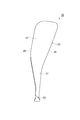
- FIG. 1 is a front view showing a fan rotor blade according to an embodiment of the present disclosure
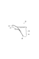
- FIG. 2 is a side view showing the fan rotor blade according to an embodiment of the present disclosure
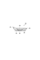
- FIG. It is a top view which shows the fan rotor blade which concerns on one Embodiment.
- 4 is a cross-sectional view showing a cross section taken along the line IV-IV in FIG.
- FIG. 5 is a schematic diagram for explaining a method for manufacturing a fan rotor blade according to an embodiment of the present disclosure.
- FIG. 6 is a schematic diagram for explaining a fan rotor blade according to an embodiment of the present disclosure.
- the fan rotor blade 10 includes an outer cover member 20 and a metal core body 30 covered with the outer cover member 20. Further, the fan rotor blade 10 includes a blade portion 21 having a blade surface shape and a support portion 22 extending at the base end of the blade portion 21, and the blade portion 21 and the support portion 22 are the outer covering member 20. Are integrally molded.
- the blade surface shape of the wing portion 21 includes a leading edge 25, a trailing edge 26, a pressure surface 23 which is a side surface on the front side in the rotational direction extending from the leading edge 25 to the trailing edge 26, and a leading edge 25 to a trailing edge 26.
- a negative pressure surface 24 which is a side surface on the rear side in the rotation direction extending up to.
- the support portion 22 has a shape that fits into an installation groove of the support body in order to fix the fan rotor blade 10 to a support body (not shown) such as a fan disk.
- the outer covering member 20 is made of a composite material including a thermoplastic resin and reinforcing fibers.
- the type of the thermoplastic resin is not particularly limited, and may be appropriately selected from known engineering plastics, super engineering plastics, and the like according to characteristics such as strength and toughness required for the fan rotor blade 10.
- the thermoplastic resin include PEI (polyetherimide), PEEK (polyetheretherketone), PEKK (polyetherketoneketone) and the like.
- the composite material may contain one kind of thermoplastic resin, and may contain two or more kinds of thermoplastic resins.
- the type of the reinforcing fiber is not particularly limited, and may be appropriately selected from known reinforcing fibers according to characteristics such as strength and toughness required for the fan rotor blade 10.
- the reinforcing fiber include carbon fiber, aramid fiber, glass fiber and the like.
- the outer cover member 20 is formed by further integrally molding preforms 41 to 44 in which a plurality of composite sheets including a thermoplastic resin and reinforcing fibers are laminated and integrated.
- the composite sheet may be obtained by impregnating a reinforced fiber with a thermoplastic resin, or may be a reinforced fiber dispersed in a thermoplastic resin.
- the composite sheet include a unidirectional prepreg in which a reinforcing fiber that is aligned in one direction is impregnated with a thermoplastic resin.
- the composite sheet may be a woven prepreg obtained by impregnating a thermoplastic resin into reinforcing fibers of a woven fabric such as plain weave, twill weave, and satin weave.
- the metal core 30 has a hollow structure.
- the hollow structure of the metal core 30 may be designed such that the weight of the metal core 30 is smaller than that of the composite material having the same volume. That is, the metal core 30 may have a specific gravity smaller than that of the composite material.
- the specific gravity of the metal core 30 may be 0.2 to 1.5, for example, and may be higher than the density of the FRP for the purpose of reinforcing rigidity and strength.
- the porosity of the metal core 30 may be 5 to 40%, for example, and may be 40% or more and less than 100%. A porosity of 100% corresponds to the case where the metal core is removed after the blade has been manufactured.
- the metal core 30 may have a hollow structure selected from, for example, a honeycomb structure, a lattice structure, and a foam structure.
- a honeycomb structure is a structure in which three-dimensional figures are arranged without gaps. For example, a regular hexagonal column may be arranged without gaps.
- the lattice structure is also called a lattice structure.
- the lattice shape in the lattice structure may be, for example, a simple lattice structure (cubic structure), an orthogonal lattice, a body-centered cubic lattice, a diamond lattice, or the like.
- the lattice spacing and the lattice thickness in the lattice structure may be appropriately changed according to the desired specific gravity.
- the lattice interval of the lattice structure may be 2 to 3 mm, for example, or 3 to 10 mm.
- the lattice thickness of the lattice structure may be 0.4 to 1.0 mm, for example.
- the foam structure may be an open cell structure or a closed cell structure.
- the metal material which comprises the metal core 30 is not specifically limited, For example, a titanium alloy, a nickel alloy, a stainless alloy etc. may be sufficient.
- the metal core 30 is disposed on the base end side of the fan rotor blade 10. Further, in the fan rotor blade 10, the metal core 30 constitutes a part of the internal structure of the base end side of the wing part 21 and a part of the internal structure of the support part 22.
- the outer shape of the metal core 30 may be a shape that ensures the mechanical strength of the fan rotor blade 10 by the outer cover member 20. Since the base end side of the wing
- a part of the thermoplastic resin constituting the outer cover member 20 may enter the hollow structure of the metal core 30.
- the thermoplastic resin that has entered the hollow structure of the metal core 30 is integrated with the composite material of the outer cover member 20, and the bonding strength between the metal core 30 and the outer cover member can be improved by the anchor effect. .
- the outer cover member 20 made of a composite material forms a blade surface shape having a pressure surface 23 and a suction surface 24.
- the positive pressure surface 23 and the negative pressure surface 24 are each comprised by another member, the outstanding mechanical strength is obtained.
- a metal core body 30 having a hollow structure is disposed between the positive pressure surface 23 and the negative pressure surface 24, and the metal core body 30 reduces the overall weight.
- heating is required for molding the composite material including the thermoplastic resin
- the core body forming the hollow structure is made of metal, deformation due to heating during molding is prevented. For this reason, the deformation
- a plurality of composite sheets are stacked and integrated to obtain a preform, and the plurality of preforms are overlapped via the metal core 30.
- a second molding step integrated by heating and pressurization.
- the preformed body 41 is produced by laminating and integrating the composite material sheets.
- the preformed body 41 includes a first molding portion 41a for forming the wing portion 21, a second molding portion 41b for extending the proximal end of the first molding portion 41a, and for forming the support portion 22, have.
- the first molding step may be, for example, a step of forming the preformed body 41 by heating and pressing a laminated body in which a plurality of composite material sheets are laminated.
- a laminated body is formed by laminating a predetermined number of composite material sheets of a predetermined size at predetermined positions corresponding to the thickness and three-dimensional shape of the preformed body 41 to be formed.
- this preformed body 41 is formed by, for example, installing in a metal mold
- the heating temperature only needs to be a temperature at which a plurality of composite sheets can be integrally molded, and may be a temperature equal to or higher than the softening point of the thermoplastic resin, for example.
- the pressurizing pressure may be a pressure at which a plurality of composite sheets are integrally formed, and may be, for example, 1 to 15 MPa.
- the preforms 42, 43 and 44 may be produced, respectively.
- the preforms 42, 43 and 44 are produced in the same manner as the preform 41.
- the preforms 42, 43 and 44 like the preform 41, are first molded parts 42a, 43a and 44a for forming the wings 21 and a second molding for forming the support part 22. Parts 42b, 43b and 44b.
- the preforms 41, 42, 43 and 44 may have a curved shape formed when the outer cover member 20 of the fan rotor blade 10 is divided into a plurality of parts in the thickness direction. Further, the preforms 41 and 44 arranged outside in the second molding step may have curved surfaces corresponding to the suction surface 24 and the pressure surface 23 of the fan rotor blade 10, respectively.
- a plurality of preforms 41, 42, 43 and 44 are overlapped via the metal core 30 and integrated by heating and pressing.
- the preforms 41, 42, 43 and 44 are arranged in this order, and the metal core 30 is arranged between the preforms 42 and 43.
- the preforms 41, 42, 43, and 44 and the metal core 30 are placed in a mold so that the mold is heated to a predetermined temperature and at a predetermined pressure. By applying pressure, the fan rotor blade 10 is formed. At this time, the thermoplastic resin of the preforms 41, 42, 43, and 44 is softened and melted at the interface between the preforms, so that the integral outer covering member 20 is formed.
- the wing part 21 is formed from the first molded parts 41 a, 42 a, 43 a and 44 a of the preforms 41, 42, 43 and 44 and the metal core body 30, and
- the support portion 2 is formed from the two molding portions 41 b, 42 b, 43 b and 44 b and the metal core body 30.
- the heating temperature may be a temperature at which the plurality of preforms 41, 42, 43, and 44 can be integrally molded, and may be, for example, a temperature equal to or higher than the softening point of the thermoplastic resin.
- the pressurizing pressure may be a pressure at which the plurality of preforms 41, 42, 43 and 44 are integrally molded, and may be, for example, 1 to 30 MPa.
- the heating and pressing conditions may be adjusted so that the thermoplastic resins of the preforms 42 and 43 that are in direct contact with the metal core 30 enter the hollow structure of the metal core 30.
- the thermoplastic resins of the preforms 42 and 43 that are in direct contact with the metal core 30 enter the hollow structure of the metal core 30.
- a configuration in which a part of the thermoplastic resin of the outer cover member 20 enters the hollow structure of the metal core 30 is formed.
- the filling amount of the thermoplastic resin in the hollow structure of the metal core 30 is increased by increasing the heating temperature and the pressurizing pressure.
- the outer cover member 20 having a blade surface shape is integrally molded from the preforms 41, 42, 43, and 44 formed from the composite prepreg including the thermoplastic resin and the reinforcing fiber. Is done.
- the metal core body 30 is arranged inside the outer cover member 20 by overlapping the plurality of preformed bodies 41, 42, 43, and 44 via the metal core body 30. For this reason, according to the said manufacturing method, the fan rotor blade 10 excellent in mechanical strength can be manufactured easily.
- the fan rotor blade that achieves weight reduction while sufficiently securing mechanical strength, and the fan rotor blade can be suitably used for an aircraft engine or the like.
Landscapes
- Engineering & Computer Science (AREA)
- Mechanical Engineering (AREA)
- General Engineering & Computer Science (AREA)
- Chemical & Material Sciences (AREA)
- Composite Materials (AREA)
- Materials Engineering (AREA)
- Aviation & Aerospace Engineering (AREA)
- Combustion & Propulsion (AREA)
- Structures Of Non-Positive Displacement Pumps (AREA)
- Casting Or Compression Moulding Of Plastics Or The Like (AREA)
- Moulding By Coating Moulds (AREA)
Abstract
熱可塑性樹脂及び強化繊維を含む複合材料によって構成されており、正圧面及び負圧面を有する翼面形状を形成する外覆部材と、正圧面と前記負圧面との間に配置されており、中空構造を有する金属芯体と、を備える、ファン動翼。
Description
本開示は、ファン動翼及びその製造方法に関する。
従来から、繊維強化プラスチック(FRP)を用いたファン動翼が開発されており、その軽量化の方法も種々検討されている。例えば、特許文献1には、割金型にプリフォーム下面体を載置し、次いでその上に中空体又は軽量芯材をセットしたのち、その上面をプリフォーム上面体で覆い、上型を閉じて金型内に熱硬化性プラスチックを注入し硬化させて、プリフォーム上下面体同士の当接周縁部を一体に接着接合することを特徴とする、送風機翼の製造法が開示されている。
近年、航空機用エンジン等に使用されるファン動翼についても軽量化が求められている。しかし、特許文献1に記載の方法では、プリフォーム上下面体同士の当接部が、プリフォーム上下面体と異なる熱硬化性プラスチックで接合されているため、当接部での強度が十分に得られないおそれがある。
本開示は、航空機用エンジン等に好適に使用できるファン動翼であって、機械的強度を十分に確保しつつ軽量化が達成されたファン動翼及びその製造方法を説明する。
本開示の一態様に係るファン動翼は、熱可塑性樹脂及び強化繊維を含む複合材料によって構成されており、正圧面及び負圧面を有する翼面形状を形成する外覆部材と、正圧面と負圧面との間に配置されており、中空構造を有する金属芯体と、を備える。
本開示によれば、航空機用エンジン等に好適に使用できるファン動翼であって、機械的強度を十分に確保しつつ軽量化が達成されたファン動翼及びその製造方法を提供することができる。
本開示の一態様に係るファン動翼は、熱可塑性樹脂及び強化繊維を含む複合材料によって構成されており、正圧面及び負圧面を有する翼面形状を形成する外覆部材と、正圧面と負圧面との間に配置されており、中空構造を有する金属芯体と、を備える。
このファン動翼では、複合材料によって構成された外覆部材が、正圧面及び負圧面を有する翼面形状を形成している。このため、正圧面及び負圧面がそれぞれ別の部材で構成される場合と比較して、優れた機械的強度が得られる。また、このファン動翼では、正圧面と負圧面との間に中空構造を有する金属芯体が配置されており、当該金属芯体によって全体の軽量化が図られている。さらに、熱可塑性樹脂を含む複合材料の成形には加熱を要するが、このファン動翼では、中空構造を成す芯体が金属製であるため成形時の加熱による変形が防止されている。このため、芯体の変形に起因する、翼面形状の変形、機械的強度の低下等が十分に防止されている。
一態様において、中空構造は、ハニカム構造、格子構造及び発泡構造から選択される構造であってよい。この場合、金属芯体の耐圧性が向上するため、外覆部材の成形時により高い圧力を付加でき、外覆部材をより精細な翼面形状を有するものとすることができる。
一態様において、外覆部材を構成する熱可塑性樹脂の一部は、金属芯体の中空構造に入り込んでいてよい。特許文献1に記載の方法では、軽量芯材とプリフォーム上下面体との接合強度が十分に確保できないという問題がある。これに対して本態様では、中空構造に入り込んだ熱可塑性樹脂によって外覆部材と金属芯体との接合強度が向上するため、ファン動翼がより優れた機械的強度を有するものとなる。
本開示の一態様に係るファン動翼の製造方法は、熱可塑性樹脂及び強化繊維を含む複数の複合材シートを積層及び一体化させて、予備成形体を得る第一の成形工程と、複数の予備成形体を、中空構造を有する金属芯体を介して重ね合せて、加熱及び加圧により一体化する第二の成形工程と、を含む。
この製造方法では、熱可塑性樹脂及び強化繊維を含む複合材シートから形成された予備成形体から、翼面形状を有する外覆部材が一体的に成形される。また、複数の予備成形体を金属芯体を介して重ね合せることで、外覆部材の内部に金属芯体が配置される。このため、上記製造方法によれば、上述の機械的強度に優れるファン動翼を容易に製造することができる。
一態様において、中空構造は、ハニカム構造、格子構造及び発泡構造から選択される構造であってよい。この場合、金属芯体が良好な耐圧性を有するため、第二の成形工程においてより高い圧力で加圧でき、より精細な翼面形状を有するファン動翼が製造できる。
以下、図面を参照しつつ、本開示の好適な実施形態について説明する。なお、図面の説明において同一要素には同一符号を付し、重複する説明を省略する。また、図面は理解を容易にするため一部を誇張して描いており、寸法比率等は図面に記載のものに限定されるものではない。
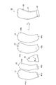
図1は、本開示の一実施形態に係るファン動翼を示す正面図であり、図2は、本開示の一実施形態に係るファン動翼を示す側面図であり、図3は、本開示の一実施形態に係るファン動翼を示す上面図である。また、図4は、図1のIV-IVに沿った断面を示す断面図である。また、図5は、本開示の一実施形態に係るファン動翼の製造方法を説明するための概略図である。図6は、本開示の一実施形態に係るファン動翼を説明するための概略図である。
図1~4に示すとおり、本実施形態に係るファン動翼10は、外覆部材20と、外覆部材20で被覆された金属芯体30と、を備えている。また、ファン動翼10は、翼面形状を有する翼部21と翼部21の基端に延設された支持部22とを有しており、翼部21及び支持部22は外覆部材20によって一体に成形されている。翼部21が有する翼面形状は、前縁25と、後縁26と、前縁25から後縁26まで延在する回転方向前側の側面である正圧面23と、前縁25から後縁26まで延在する回転方向後側の側面である負圧面24とによって画成されている。支持部22は、ファンディスク等の支持体(図示しない)にファン動翼10を固定するため、支持体が有する設置溝と嵌合する形状を有している。
外覆部材20は、熱可塑性樹脂及び強化繊維を含む複合材料によって構成されている。熱可塑性樹脂の種類は特に限定されず、ファン動翼10に要求される強度及び靭性などの特性に応じて、公知のエンジニアリングプラスチック、スーパーエンジニアリングプラスチック等から適宜選択してよい。熱可塑性樹脂の好適な例としては、PEI(ポリエーテルイミド)、PEEK(ポリエーテルエーテルケトン)、PEKK(ポリエーテルケトンケトン)等が挙げられる。複合材料は1種の熱可塑性樹脂を含むものであってよく、2種以上の熱可塑性樹脂を含むものであってもよい。強化繊維の種類も特に限定されず、ファン動翼10に要求される強度及び靭性などの特性に応じて、公知の強化繊維から適宜選択してよい。強化繊維の好適な例としては、炭素繊維、アラミド繊維、ガラス繊維等が挙げられる。
外覆部材20は、後述するように、熱可塑性樹脂及び強化繊維を含む複数の複合材シートを積層及び一体化した予備成形体41~44を、さらに一体に成形して形成されたものである。複合材シートは、例えば、強化繊維に熱可塑性樹脂を含浸させたものであってよく、熱可塑性樹脂中に強化繊維を分散させたものであってよい。複合材シートとしては、例えば、一方向に引きそろえられた強化繊維に熱可塑性樹脂を含浸させた一方向プリプレグが挙げられる。また、複合材シートは、平織り、綾織り、朱子織りなどの織物の強化繊維に熱可塑性樹脂を含浸させた織物プリプレグであってもよい。
金属芯体30は中空構造を有している。金属芯体30の中空構造は、金属芯体30の重量が同体積の複合材料より小さくなるように設計されたものであってよい。すなわち、金属芯体30は、複合材料より小さい比重を有していてよい。金属芯体30の比重は、例えば0.2~1.5であってよく、剛性、強度の補強のためならFRPの密度より高くなってもよい。また、金属芯体30の空隙率は、例えば5~40%であってよく、40%以上100%未満であってもよい。空隙率100%は、翼を製造後金属芯体を抜いた場合に相当する。
金属芯体30は、例えば、ハニカム構造、格子構造及び発泡構造から選択される中空構造を有するものであってよい。この場合、金属芯体の耐圧性が向上するため、外覆部材の成形時により高い圧力を付加でき、外覆部材をより精細な翼面形状を有するものとすることができる。ハニカム構造は、立体図形を隙間なく並べた構造であり、例えば正六角柱を隙間なく並べた構造であってよい。格子構造は、ラティス構造ともいう。格子構造における格子形状は、例えば、単純格子構造(立方体構造)、直交格子、体心立方格子、ダイヤモンド格子等であってよい。格子構造における格子間隔及び格子太さは、所望の比重に応じて適宜変更してよい。格子構造の格子間隔は、例えば2~3mmであってよく、3~10mmであってもよい。格子構造の格子太さは、例えば0.4~1.0mmであってよい。発泡構造は、連続気泡構造であってよく、独立気泡構造であってもよい。金属芯体30を構成する金属材料は特に限定されず、例えばチタン合金、ニッケル合金、ステンレス合金等であってよい。
金属芯体30は、ファン動翼10の基端側に配置されている。また、ファン動翼10において、金属芯体30は、翼部21の基端側の内部構造の一部、及び、支持部22の内部構造の一部を構成している。金属芯体30の外形形状は、ファン動翼10の機械的強度が外覆部材20によって確保される形状であればよい。翼部21の基端側及び支持部22は、ファン動翼10のなかで比較的厚みを有する箇所であるため、これらの内部構造に配置される金属芯体30は外形形状を大きくできる。
一態様において、外覆部材20を構成する熱可塑性樹脂の一部が、金属芯体30の中空構造に入り込んでいてよい。金属芯体30の中空構造内に入り込んだ熱可塑性樹脂は、外覆部材20の複合材料と一体化しており、アンカー効果により金属芯体30と外覆部材との接合強度を向上させることができる。
ファン動翼10では、複合材料によって構成された外覆部材20が、正圧面23及び負圧面24を有する翼面形状を形成している。このため、正圧面23及び負圧面24がそれぞれ別の部材で構成される場合と比較して、優れた機械的強度が得られる。また、このファン動翼10では、正圧面23と負圧面24との間に中空構造を有する金属芯体30が配置されており、当該金属芯体30によって全体の軽量化が図られている。さらに、熱可塑性樹脂を含む複合材料の成形には加熱を要するが、このファン動翼10では、中空構造を成す芯体が金属製であるため成形時の加熱による変形が防止されている。このため、芯体の変形に起因する、翼面形状の変形、機械的強度の低下等が十分に防止されている。
次に、図5を参照しながら本実施形態に係るファン動翼10の製造方法について説明する。
本実施形態に係る製造方法は、複数の複合材シートを積層及び一体化させて予備成形体を得る第一の成形工程と、複数の予備成形体を金属芯体30を介して重ね合わせて、加熱及び加圧により一体化する第二の成形工程と、を含む。
第一の成形工程では、例えば、複合材シートを積層及び一体化させることで予備成形体41が作製される。予備成形体41は、翼部21を形成するための第一成形部41aと、第一成形部41aの基端に延設された、支持部22を形成するための第二成形部41bと、を有している。
第一の成形工程は、例えば、複数の複合材シートを積層した積層体を加熱及び加圧して、予備成形体41を形成する工程であってよい。形成される予備成形体41の厚さ及び立体形状に対応して、所定の位置に所定の大きさの複合材シートを所定の枚数分積層することで、積層体が形成される。そして、この積層体を、例えば金型内に設置して、金型を所定の温度に加熱しつつ所定の圧力で加圧することで、予備成形体41が形成される。加熱の温度は、複数の複合材シートを一体に成形できる温度であればよく、例えば熱可塑性樹脂の軟化点以上の温度であってよい。加圧の圧力は、複数の複合材シートが一体に成形される圧力であればよく、例えば1~15MPaであってよい。
第一の成形工程では、予備成形体42、43及び44をそれぞれ作製してもよい。予備成形体42、43及び44は、予備成形体41と同様にして作製される。また、予備成形体42、43及び44は、予備成形体41と同様に、翼部21を形成するための第一成形部42a、43a及び44aと、支持部22を形成するための第二成形部42b、43b及び44bとを有している。
予備成形体41、42、43及び44は、ファン動翼10の外覆部材20を厚さ方向に複数分割したときに形成される曲面形状を有していてよい。また、第二の成形工程で外側に配置される予備成形体41及び44は、それぞれファン動翼10の負圧面24及び正圧面23に対応する曲面形状を有していてよい。
第二の成形工程では、複数の予備成形体41、42、43及び44を、金属芯体30を介して重ね合わせて、加熱及び加圧により一体化する。予備成形体41、42、43及び44はこの順で配置され、金属芯体30は予備成形体42及び43の間に配置される。
第二の成形工程では、例えば、予備成形体41、42、43及び44と金属芯体30とを重ね合わせて金型内に配置し、金型を所定の温度に加熱しつつ所定の圧力で加圧することで、ファン動翼10が形成される。このとき、予備成形体41、42、43及び44の熱可塑性樹脂が軟化し、各予備成形体間の境界面で溶融することによって、一体の外覆部材20が形成される。また、予備成形体41、42、43及び44の第一成形部41a、42a、43a及び44aと金属芯体30とから翼部21が形成され、予備成形体41、42、43及び44の第二成形部41b、42b、43b及び44bと金属芯体30とから支持部2が形成される。
第二の成形工程において、加熱の温度は、複数の予備成形体41、42、43及び44を一体に成形できる温度であればよく、例えば熱可塑性樹脂の軟化点以上の温度であってよい。加圧の圧力は、複数の予備成形体41、42、43及び44が一体に成形される圧力であればよく、例えば1~30MPaであってよい。
第二の成形工程では、金属芯体30に直接接する予備成形体42及び43の熱可塑性樹脂が、金属芯体30の中空構造内に入り込むように加熱及び加圧の条件を調整してよい。これにより、外覆部材20の熱可塑性樹脂の一部が金属芯体30の中空構造に入り込んだ構成が形成される。なお、加熱の温度及び加圧の圧力を高くすることで、金属芯体30の中空構造内への熱可塑性樹脂の充填量が多くなる。
本実施形態に係る製造方法では、熱可塑性樹脂及び強化繊維を含む複合材プリプレグから形成された予備成形体41、42、43及び44から、翼面形状を有する外覆部材20が一体的に成形される。また、複数の予備成形体41、42、43及び44を金属芯体30を介して重ね合せることで、外覆部材20の内部に金属芯体30が配置される。このため、上記製造方法によれば、機械的強度に優れるファン動翼10を容易に製造することができる。
以上、本開示の好適な実施形態について説明したが、本開示は上記実施形態に限定されるものではない。
本開示によれば、機械的強度を十分に確保しつつ軽量化が達成されたファン動翼が得られ、当該ファン動翼は航空機用エンジン等に好適に使用できる。
10 ファン動翼
20 外覆部材
21 翼部
22 支持部
23 正圧面
24 負圧面
25 前縁
26 後縁
30 金属芯体
41~44 予備成形体
20 外覆部材
21 翼部
22 支持部
23 正圧面
24 負圧面
25 前縁
26 後縁
30 金属芯体
41~44 予備成形体
Claims (6)
- 熱可塑性樹脂及び強化繊維を含む複合材料によって構成されており、正圧面及び負圧面を有する翼面形状を形成する外覆部材と、
前記正圧面と前記負圧面との間に配置されており、中空構造を有する金属芯体と、
を備える、ファン動翼。 - 前記中空構造が、ハニカム構造、格子構造及び発泡構造から選択される、請求項1に記載のファン動翼。
- 前記外覆部材を構成する前記熱可塑性樹脂の一部が、前記金属芯体の前記中空構造に入り込んでいる、請求項1に記載のファン動翼。
- 前記外覆部材を構成する前記熱可塑性樹脂の一部が、前記金属芯体の前記中空構造に入り込んでいる、請求項2に記載のファン動翼。
- 熱可塑性樹脂及び強化繊維を含む複数の複合材シートを積層及び一体化させて、予備成形体を得る第一の成形工程と、
複数の前記予備成形体を、中空構造を有する金属芯体を介して重ね合せて、加熱及び加圧により一体化する第二の成形工程と、
を含む、ファン動翼の製造方法。 - 前記中空構造が、ハニカム構造、格子構造及び発泡構造から選択される、請求項5に記載のファン動翼の製造方法。
Priority Applications (3)
| Application Number | Priority Date | Filing Date | Title |
|---|---|---|---|
| EP17862837.6A EP3530958A4 (en) | 2016-10-18 | 2017-10-16 | Fan rotor blade and method of manufacturing same |
| US16/342,016 US20190249684A1 (en) | 2016-10-18 | 2017-10-16 | Fan rotor blade and method of manufacturing same |
| CA3040845A CA3040845C (en) | 2016-10-18 | 2017-10-16 | Fan rotor blade and method of manufacturing same |
Applications Claiming Priority (2)
| Application Number | Priority Date | Filing Date | Title |
|---|---|---|---|
| JP2016-204392 | 2016-10-18 | ||
| JP2016204392A JP2018066289A (ja) | 2016-10-18 | 2016-10-18 | ファン動翼及びその製造方法 |
Publications (1)
| Publication Number | Publication Date |
|---|---|
| WO2018074423A1 true WO2018074423A1 (ja) | 2018-04-26 |
Family
ID=62018650
Family Applications (1)
| Application Number | Title | Priority Date | Filing Date |
|---|---|---|---|
| PCT/JP2017/037393 Ceased WO2018074423A1 (ja) | 2016-10-18 | 2017-10-16 | ファン動翼及びその製造方法 |
Country Status (5)
| Country | Link |
|---|---|
| US (1) | US20190249684A1 (ja) |
| EP (1) | EP3530958A4 (ja) |
| JP (1) | JP2018066289A (ja) |
| CA (1) | CA3040845C (ja) |
| WO (1) | WO2018074423A1 (ja) |
Cited By (2)
| Publication number | Priority date | Publication date | Assignee | Title |
|---|---|---|---|---|
| CN109372798A (zh) * | 2018-12-13 | 2019-02-22 | 中国航发沈阳发动机研究所 | 一种风扇叶片 |
| US10774653B2 (en) | 2018-12-11 | 2020-09-15 | Raytheon Technologies Corporation | Composite gas turbine engine component with lattice structure |
Families Citing this family (4)
| Publication number | Priority date | Publication date | Assignee | Title |
|---|---|---|---|---|
| CN109989938B (zh) * | 2019-03-22 | 2024-02-06 | 中国科学院工程热物理研究所 | 一种航空发动机的风扇叶片及其制作方法 |
| JP7411462B2 (ja) * | 2020-03-17 | 2024-01-11 | 三菱重工業株式会社 | 複合材翼、回転機械及び複合材翼の成形方法 |
| US12391010B2 (en) | 2023-01-13 | 2025-08-19 | Rtx Corporation | Methods of manufacture for composite blades |
| US12442305B2 (en) | 2023-06-01 | 2025-10-14 | General Electric Company | Composite airfoil assembly for a turbine engine |
Citations (6)
| Publication number | Priority date | Publication date | Assignee | Title |
|---|---|---|---|---|
| JPH04316845A (ja) * | 1991-04-16 | 1992-11-09 | Mitsubishi Heavy Ind Ltd | 複合材翼型成形方法 |
| JPH071607A (ja) | 1993-06-15 | 1995-01-06 | Mitsubishi Plastics Ind Ltd | 繊維強化プラスチック送風機翼の製造法 |
| JP2000356198A (ja) * | 1999-06-11 | 2000-12-26 | Mitsubishi Heavy Ind Ltd | 軸流送風機用動翼 |
| JP2002242886A (ja) * | 2000-12-12 | 2002-08-28 | Usui Internatl Ind Co Ltd | 樹脂製ブレードを有するファン |
| JP2009024695A (ja) * | 2007-07-23 | 2009-02-05 | General Electric Co <Ge> | 翼形部及び翼形部前縁を保護する方法 |
| US20150198173A1 (en) * | 2014-01-16 | 2015-07-16 | United Technologies Corporation | Fan Blade With Variable Thickness Composite Cover |
Family Cites Families (5)
| Publication number | Priority date | Publication date | Assignee | Title |
|---|---|---|---|---|
| CA2042218A1 (en) * | 1990-07-20 | 1992-01-21 | Jan C. Schilling | Composite airfoil with increased shear capability |
| US5720597A (en) * | 1996-01-29 | 1998-02-24 | General Electric Company | Multi-component blade for a gas turbine |
| EP2479217B1 (en) * | 2009-09-16 | 2019-08-28 | Toray Industries, Inc. | Binder composition, reinforcing-fiber base material, preform, fiber-reinforced composite material, and manufacturing method therefor |
| US9004873B2 (en) * | 2010-12-27 | 2015-04-14 | Rolls-Royce Corporation | Airfoil, turbomachine and gas turbine engine |
| US10035174B2 (en) * | 2015-02-09 | 2018-07-31 | United Technologies Corporation | Open-cell reticulated foam |
-
2016
- 2016-10-18 JP JP2016204392A patent/JP2018066289A/ja active Pending
-
2017
- 2017-10-16 US US16/342,016 patent/US20190249684A1/en not_active Abandoned
- 2017-10-16 EP EP17862837.6A patent/EP3530958A4/en not_active Withdrawn
- 2017-10-16 CA CA3040845A patent/CA3040845C/en not_active Expired - Fee Related
- 2017-10-16 WO PCT/JP2017/037393 patent/WO2018074423A1/ja not_active Ceased
Patent Citations (6)
| Publication number | Priority date | Publication date | Assignee | Title |
|---|---|---|---|---|
| JPH04316845A (ja) * | 1991-04-16 | 1992-11-09 | Mitsubishi Heavy Ind Ltd | 複合材翼型成形方法 |
| JPH071607A (ja) | 1993-06-15 | 1995-01-06 | Mitsubishi Plastics Ind Ltd | 繊維強化プラスチック送風機翼の製造法 |
| JP2000356198A (ja) * | 1999-06-11 | 2000-12-26 | Mitsubishi Heavy Ind Ltd | 軸流送風機用動翼 |
| JP2002242886A (ja) * | 2000-12-12 | 2002-08-28 | Usui Internatl Ind Co Ltd | 樹脂製ブレードを有するファン |
| JP2009024695A (ja) * | 2007-07-23 | 2009-02-05 | General Electric Co <Ge> | 翼形部及び翼形部前縁を保護する方法 |
| US20150198173A1 (en) * | 2014-01-16 | 2015-07-16 | United Technologies Corporation | Fan Blade With Variable Thickness Composite Cover |
Non-Patent Citations (1)
| Title |
|---|
| See also references of EP3530958A4 |
Cited By (6)
| Publication number | Priority date | Publication date | Assignee | Title |
|---|---|---|---|---|
| US10774653B2 (en) | 2018-12-11 | 2020-09-15 | Raytheon Technologies Corporation | Composite gas turbine engine component with lattice structure |
| EP3677749A3 (en) * | 2018-12-11 | 2020-09-16 | United Technologies Corporation | Composite gas turbine engine component with lattice structure |
| US11168568B2 (en) | 2018-12-11 | 2021-11-09 | Raytheon Technologies Corporation | Composite gas turbine engine component with lattice |
| EP3971390A1 (en) * | 2018-12-11 | 2022-03-23 | Raytheon Technologies Corporation | Composite platform with lattice structure |
| EP4357621A3 (en) * | 2018-12-11 | 2024-06-19 | RTX Corporation | Composite gas turbine engine component with lattice structure |
| CN109372798A (zh) * | 2018-12-13 | 2019-02-22 | 中国航发沈阳发动机研究所 | 一种风扇叶片 |
Also Published As
| Publication number | Publication date |
|---|---|
| JP2018066289A (ja) | 2018-04-26 |
| EP3530958A4 (en) | 2020-05-20 |
| US20190249684A1 (en) | 2019-08-15 |
| EP3530958A1 (en) | 2019-08-28 |
| CA3040845A1 (en) | 2018-04-26 |
| CA3040845C (en) | 2021-03-23 |
Similar Documents
| Publication | Publication Date | Title |
|---|---|---|
| WO2018074423A1 (ja) | ファン動翼及びその製造方法 | |
| EP2476540A1 (en) | Stiffening sheet for use in a fibre reinforced laminate, fibre reinforced laminate and wind turbine blade, and a method of manufacturing a fibre reinforced laminate | |
| CN109562578B (zh) | 复合材料结构体和复合材料结构体的制造方法 | |
| US10273935B2 (en) | Rotor blades having structural skin insert and methods of making same | |
| EP2388477B1 (en) | Blade of a wind turbine | |
| EP2113373A1 (en) | Method for manufacturing of a fibre reinforced laminate and of a laterally extended material which has in a first lateral direction a greater stiffness than in a second lateral direction | |
| US20150217850A1 (en) | Laminated i-blade stringer | |
| JP2011516316A (ja) | 両側にカバー層を備えたコア複合体を製造する方法 | |
| US20110070092A1 (en) | Hybrid component | |
| US20110135486A1 (en) | Belt of a rotor blade of a wind power plant | |
| CN107225773A (zh) | 用于组装加强的复合结构的方法 | |
| CN110678306B (zh) | 复合叶片的成型方法、复合叶片及复合叶片的成型模 | |
| WO2018207702A1 (ja) | 複合材翼及び複合材翼の製造方法 | |
| CN101171122B (zh) | 制造中空纤维增强结构件的方法 | |
| JP2013018228A (ja) | ガスタービンエンジン用ブレードの製造方法 | |
| US11383828B2 (en) | Landing gear of rotorcraft | |
| US20210316526A1 (en) | Fiber-reinforced composite blank, fiber-reinforced composite component, rotor blade element, rotor blade and wind turbine and method for producing a fiber-reinforced composite blank and method for producing a fiber-reinforced composite component | |
| CN101341063B (zh) | 特别用于脚踏车的超轻车座结构及其支撑框架的制作方法 | |
| US20130213560A1 (en) | Method for producing parts made from composite materials with a braided covering | |
| JP3590346B2 (ja) | Frp構造体 | |
| KR102638697B1 (ko) | 무인항공기용 섬유강화플라스틱 프로펠러 및 이의 제조방법 | |
| EP2582505B1 (en) | Mould tools | |
| US20250010974A1 (en) | Hollow structure and propeller blade | |
| JP5398110B2 (ja) | 自動車用ボンネット | |
| WO2026048361A1 (ja) | 成形品 |
Legal Events
| Date | Code | Title | Description |
|---|---|---|---|
| 121 | Ep: the epo has been informed by wipo that ep was designated in this application |
Ref document number: 17862837 Country of ref document: EP Kind code of ref document: A1 |
|
| ENP | Entry into the national phase |
Ref document number: 3040845 Country of ref document: CA |
|
| NENP | Non-entry into the national phase |
Ref country code: DE |
|
| ENP | Entry into the national phase |
Ref document number: 2017862837 Country of ref document: EP Effective date: 20190520 |