WO2018084137A1 - ユーザ端末及び無線通信方法 - Google Patents
ユーザ端末及び無線通信方法 Download PDFInfo
- Publication number
- WO2018084137A1 WO2018084137A1 PCT/JP2017/039286 JP2017039286W WO2018084137A1 WO 2018084137 A1 WO2018084137 A1 WO 2018084137A1 JP 2017039286 W JP2017039286 W JP 2017039286W WO 2018084137 A1 WO2018084137 A1 WO 2018084137A1
- Authority
- WO
- WIPO (PCT)
- Prior art keywords
- pucch
- user terminal
- transmission
- uci
- slot
- Prior art date
- Legal status (The legal status is an assumption and is not a legal conclusion. Google has not performed a legal analysis and makes no representation as to the accuracy of the status listed.)
- Ceased
Links
Images







Classifications
-
- H—ELECTRICITY
- H04—ELECTRIC COMMUNICATION TECHNIQUE
- H04W—WIRELESS COMMUNICATION NETWORKS
- H04W72/00—Local resource management
- H04W72/12—Wireless traffic scheduling
- H04W72/1263—Mapping of traffic onto schedule, e.g. scheduled allocation or multiplexing of flows
- H04W72/1268—Mapping of traffic onto schedule, e.g. scheduled allocation or multiplexing of flows of uplink data flows
-
- H—ELECTRICITY
- H04—ELECTRIC COMMUNICATION TECHNIQUE
- H04L—TRANSMISSION OF DIGITAL INFORMATION, e.g. TELEGRAPHIC COMMUNICATION
- H04L1/00—Arrangements for detecting or preventing errors in the information received
- H04L1/12—Arrangements for detecting or preventing errors in the information received by using return channel
- H04L1/16—Arrangements for detecting or preventing errors in the information received by using return channel in which the return channel carries supervisory signals, e.g. repetition request signals
- H04L1/18—Automatic repetition systems, e.g. Van Duuren systems
- H04L1/1829—Arrangements specially adapted for the receiver end
- H04L1/1861—Physical mapping arrangements
-
- H—ELECTRICITY
- H04—ELECTRIC COMMUNICATION TECHNIQUE
- H04L—TRANSMISSION OF DIGITAL INFORMATION, e.g. TELEGRAPHIC COMMUNICATION
- H04L1/00—Arrangements for detecting or preventing errors in the information received
- H04L1/12—Arrangements for detecting or preventing errors in the information received by using return channel
- H04L1/16—Arrangements for detecting or preventing errors in the information received by using return channel in which the return channel carries supervisory signals, e.g. repetition request signals
- H04L1/18—Automatic repetition systems, e.g. Van Duuren systems
- H04L1/1829—Arrangements specially adapted for the receiver end
- H04L1/1854—Scheduling and prioritising arrangements
-
- H—ELECTRICITY
- H04—ELECTRIC COMMUNICATION TECHNIQUE
- H04L—TRANSMISSION OF DIGITAL INFORMATION, e.g. TELEGRAPHIC COMMUNICATION
- H04L1/00—Arrangements for detecting or preventing errors in the information received
- H04L1/12—Arrangements for detecting or preventing errors in the information received by using return channel
- H04L1/16—Arrangements for detecting or preventing errors in the information received by using return channel in which the return channel carries supervisory signals, e.g. repetition request signals
- H04L1/18—Automatic repetition systems, e.g. Van Duuren systems
- H04L1/1867—Arrangements specially adapted for the transmitter end
- H04L1/1896—ARQ related signaling
-
- H—ELECTRICITY
- H04—ELECTRIC COMMUNICATION TECHNIQUE
- H04L—TRANSMISSION OF DIGITAL INFORMATION, e.g. TELEGRAPHIC COMMUNICATION
- H04L27/00—Modulated-carrier systems
- H04L27/26—Systems using multi-frequency codes
-
- H—ELECTRICITY
- H04—ELECTRIC COMMUNICATION TECHNIQUE
- H04L—TRANSMISSION OF DIGITAL INFORMATION, e.g. TELEGRAPHIC COMMUNICATION
- H04L5/00—Arrangements affording multiple use of the transmission path
- H04L5/003—Arrangements for allocating sub-channels of the transmission path
- H04L5/0053—Allocation of signalling, i.e. of overhead other than pilot signals
-
- H—ELECTRICITY
- H04—ELECTRIC COMMUNICATION TECHNIQUE
- H04L—TRANSMISSION OF DIGITAL INFORMATION, e.g. TELEGRAPHIC COMMUNICATION
- H04L5/00—Arrangements affording multiple use of the transmission path
- H04L5/0091—Signalling for the administration of the divided path, e.g. signalling of configuration information
- H04L5/0094—Indication of how sub-channels of the path are allocated
-
- H—ELECTRICITY
- H04—ELECTRIC COMMUNICATION TECHNIQUE
- H04W—WIRELESS COMMUNICATION NETWORKS
- H04W28/00—Network traffic management; Network resource management
- H04W28/02—Traffic management, e.g. flow control or congestion control
- H04W28/06—Optimizing the usage of the radio link, e.g. header compression, information sizing, discarding information
-
- H—ELECTRICITY
- H04—ELECTRIC COMMUNICATION TECHNIQUE
- H04W—WIRELESS COMMUNICATION NETWORKS
- H04W72/00—Local resource management
- H04W72/04—Wireless resource allocation
-
- H—ELECTRICITY
- H04—ELECTRIC COMMUNICATION TECHNIQUE
- H04W—WIRELESS COMMUNICATION NETWORKS
- H04W72/00—Local resource management
- H04W72/04—Wireless resource allocation
- H04W72/044—Wireless resource allocation based on the type of the allocated resource
- H04W72/0446—Resources in time domain, e.g. slots or frames
-
- H—ELECTRICITY
- H04—ELECTRIC COMMUNICATION TECHNIQUE
- H04W—WIRELESS COMMUNICATION NETWORKS
- H04W72/00—Local resource management
- H04W72/12—Wireless traffic scheduling
-
- H—ELECTRICITY
- H04—ELECTRIC COMMUNICATION TECHNIQUE
- H04W—WIRELESS COMMUNICATION NETWORKS
- H04W72/00—Local resource management
- H04W72/20—Control channels or signalling for resource management
- H04W72/21—Control channels or signalling for resource management in the uplink direction of a wireless link, i.e. towards the network
-
- H—ELECTRICITY
- H04—ELECTRIC COMMUNICATION TECHNIQUE
- H04W—WIRELESS COMMUNICATION NETWORKS
- H04W72/00—Local resource management
- H04W72/20—Control channels or signalling for resource management
- H04W72/23—Control channels or signalling for resource management in the downlink direction of a wireless link, i.e. towards a terminal
-
- H—ELECTRICITY
- H04—ELECTRIC COMMUNICATION TECHNIQUE
- H04L—TRANSMISSION OF DIGITAL INFORMATION, e.g. TELEGRAPHIC COMMUNICATION
- H04L5/00—Arrangements affording multiple use of the transmission path
- H04L5/0001—Arrangements for dividing the transmission path
- H04L5/0003—Two-dimensional division
- H04L5/0005—Time-frequency
- H04L5/0007—Time-frequency the frequencies being orthogonal, e.g. OFDM(A) or DMT
- H04L5/001—Time-frequency the frequencies being orthogonal, e.g. OFDM(A) or DMT the frequencies being arranged in component carriers
-
- H—ELECTRICITY
- H04—ELECTRIC COMMUNICATION TECHNIQUE
- H04L—TRANSMISSION OF DIGITAL INFORMATION, e.g. TELEGRAPHIC COMMUNICATION
- H04L5/00—Arrangements affording multiple use of the transmission path
- H04L5/003—Arrangements for allocating sub-channels of the transmission path
- H04L5/0053—Allocation of signalling, i.e. of overhead other than pilot signals
- H04L5/0055—Physical resource allocation for ACK/NACK
Definitions
- the present invention relates to a user terminal and a wireless communication method in a next generation mobile communication system.
- LTE Long Term Evolution
- Non-Patent Document 1 LTE-A (LTE-Advanced), FRA (Future Radio Access), 4G, 5G, 5G + (plus), NR ( New RAT) and LTE Rel.14, 15 ⁇ ) are also being considered.
- CA Carrier Aggregation
- CC Component Carrier
- UE User Equipment
- DC Dual Connectivity
- CG Cell Group
- CC Carrier
- Inter-eNB CA inter-base station CA
- a transmission time interval (TTI: Transmission Time Interval) (also referred to as a subframe) is used, and a downlink (DL: Downlink) and / or Uplink (UL) communication is performed.
- TTI Transmission Time Interval
- DL Downlink
- UL Uplink
- the 1 ms TTI is a transmission time unit of one channel-encoded data packet, and is a processing unit such as scheduling, link adaptation, and retransmission control (HARQ: Hybrid Automatic Repeat reQuest).
- HARQ Hybrid Automatic Repeat reQuest
- the user terminal uses the UL control channel (for example, PUCCH: Physical Uplink Control Channel) or the UL data channel (for example, PUSCH: Physical Uplink Shared Channel). And transmits uplink control information (UCI).
- UCI includes at least one of a scheduling request (SR), retransmission control information for DL data (HARQ-ACK (Acknowledge), ACK or NACK (Negative ACk)), and channel state information (CSI). including.
- SR scheduling request
- HARQ-ACK Acknowledge
- ACK or NACK Negative ACk
- CSI channel state information
- eMBB enhanced Mobile Broad Band
- IoT Internet of Things
- MTC Machine Type Communication
- URLLC Ultra-reliable and low latency communication
- a plurality of slots having different time lengths in a slot (UL duration: UL duration)
- UL duration UL duration
- a slot for performing UL communication with all symbols UL only slot
- a slot with more symbols for UL communication than symbols for performing DL communication UL centric slot
- a symbol for performing UL communication from a symbol for performing DL communication It is assumed that the number of slots (DL centric slot) and the slot for performing DL communication with all symbols (DL only slot) are also used.
- the present invention has been made in view of the above points, and an object thereof is to provide a user terminal and a wireless communication method capable of appropriately transmitting UCI in a future wireless communication system.
- One aspect of the user terminal includes: a transmitter that transmits uplink control information (UCI) in at least one of a plurality of slots having different time lengths of UL periods; and a controller that controls transmission of the UCI.
- the control unit controls an uplink (UL) control channel used for transmission of the UCI based on an explicit instruction from a radio base station or an implicit determination by a user terminal. .
- a user terminal in a future wireless communication system, can appropriately transmit uplink control information (UCI).
- UCI uplink control information
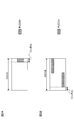
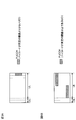
- 2A and 2B are diagrams illustrating an example of a PUCCH configuration according to the first aspect.
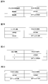
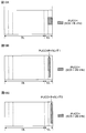
- 3A to 3C are diagrams illustrating a first determination example of the PUCCH format / structure according to the second aspect.
- 4A and 4B are diagrams illustrating a second determination example of the PUCCH format / structure according to the second aspect.
- 5A and 5B are diagrams illustrating a third determination example of the PUCCH format / structure according to the second aspect.
- 6A and 6B are diagrams illustrating a fourth determination example of the PUCCH format / structure according to the second aspect.
- FIGS. 10A to 10C are diagrams illustrating an example of the PUCCH pneumology according to the second mode.
- 11A to 11C are diagrams illustrating an example of DCI according to the second mode.
- 12A and 12B are diagrams illustrating an example of UCI transmission control according to the third mode.
- 13A and 13B are diagrams illustrating another example of UCI transmission control according to the third mode.
- time units for example, frames, subframes, slots, minislots, subslots, transmission time intervals (for example, frames different from those of the existing LTE system (LTE Rel. 13 or earlier)
- TTI Transmission Time Interval
- the subframe is a time unit having a predetermined time length (for example, 1 ms) regardless of the neurology.
- the slot is a time unit based on the neurology (for example, subcarrier interval and / or symbol length) and the number of symbols. For example, when the subcarrier interval is 15 kHz or 30 kHz, the number of symbols per slot may be 7 or 14 symbols. On the other hand, when the subcarrier interval is 60 kHz or more, the number of symbols per slot may be 14 symbols.
- the slot may include a plurality of mini (sub) slots.
- FIG. 1 is a diagram illustrating an example of a configuration (also referred to as a structure, a type, or the like) of a slot used in a future wireless communication system.
- FIG. 1 shows the configuration of slots in the time domain.
- a DL control channel, a DL data channel (also referred to as a DL shared channel, etc.) or a UL data channel (UL shared channel, etc.) and a UL control channel are time-division multiplexed. Absent.
- the DL data channel and / or the UL data channel and the DL control channel may not be divided in time, and may be frequency multiplexed / code multiplexed / spatial multiplexed.
- the DL data channel and / or the UL data channel and the UL control channel are the same, and may not be divided in time, and may be frequency multiplexed / code multiplexed / spatial multiplexed in the same time interval (eg, symbol).
- the user terminal controls reception of the DL data channel and / or transmission of the UL data channel based on downlink control information (DCI: Downlink Control Information) transmitted on the DL control channel.
- DCI Downlink Control Information
- a slot for receiving a DL data channel may be referred to as a DL centric slot or the like because DL communication is mainly performed.
- a slot for receiving a UL data channel may be called a UL centric slot or the like because UL communication is mainly performed.
- the user terminal transmits DL data channel retransmission control information (HARQ-ACK: Hybrid Automatic Repeat reQuest-Acknowledge, also called ACK or NACK (A / N), etc.) to the UL control channel in the same slot as the DL data channel. You may feed back using. Alternatively, the user terminal may feed back the A / N on the UL control channel or UL data channel of the subsequent slot.
- HARQ-ACK Hybrid Automatic Repeat reQuest-Acknowledge, also called ACK or NACK (A / N), etc.
- a switching time (gap interval) between DL and UL is set between the DL data channel and the UL control channel and / or between the DL control channel and the UL data channel. May be. Also, a switching time (gap interval) between UL and DL may be set between the UL control channel and the start time of the next slot or frame (subframe or TTI).
- Switching time (gap section) between UL and DL may be set in the section by advance (TA).
- TA advance
- the gap interval between the DL data channel and the UL control channel and / or the DL control channel and the UL data channel in FIG. 1 is the number of integer symbols such as 1 symbol, 2 symbols, and 3 symbols, for example. It can be.
- assignment that completes transmission / reception control may be performed in the same slot.
- This assignment is also referred to as self-contained assignment.
- a slot in which self-contained allocation is performed may be referred to as a self-contained slot.
- the self-contained slot may be referred to as a self-contained subframe, a self-contained TTI, a self-contained symbol set, or other names, for example.
- the user terminal may receive the DL data channel based on the DL control channel and transmit the HARQ-ACK of the DL data channel.
- self-contained slots or subframes for example, ultra-low delay feedback of 1 ms or less can be realized, so that the delay time can be reduced.
- a slot configuration (also referred to as UL centric) in which the DL control channel, the UL data channel, and the UL control channel are arranged can be used.
- the user terminal can transmit UL signals (UL data, measurement reports, etc.) in the same (or subsequent) slots based on DCI transmitted on the DL control channel.
- a plurality of slots having different time lengths in the UL period in the slot for example, a DL centric slot in which the UL period is shorter than the DL period, and a UL in which the UL period is longer than the DL period
- a centric slot, a UL only slot that performs only UL communication, and a DL only slot that performs only DL communication and has no UL period are used.
- the present inventors have studied a method for appropriately transmitting UCI in at least one of a plurality of slots having different time lengths of UL periods, and have reached the present invention. Specifically, the present inventors have conceived of controlling an uplink (UL) control channel used for transmitting the UCI based on an explicit instruction from a radio base station or an implicit determination by a user terminal. .
- UL uplink
- the PUCCH configuration defines a configuration necessary for at least one of PUCCH generation processing, transmission processing, and reception processing.
- the PUCCH configuration includes PUCCH time length, payload, number of symbols, number of resource blocks (PRB: Physical Resource Block), resource (for example, at least one of symbols, PRB, and spreading code), waveform, timing, and neurology.
- a signal generation processing method such as a modulation method and a spread method, a multiplexing method of a plurality of user terminals, a transmission method (for example, multi-antenna transmission, simultaneous transmission of PUSCH and PUCCH (simultaneous PUCCH and PUSCH), UCI transmission using PUSCH ( UCI piggyback on PUSCH)).
- the user terminal may be configured to be able to use a plurality of PUCCH configurations having at least different time lengths.
- the plurality of PUCCH configurations include a first PUCCH configuration configured with a relatively short time length (for example, 1 or 2 symbols), and a second PUCCH configuration having a longer time length than the first PUCCH configuration. , At least.
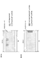
- FIG. 2 is a diagram illustrating an example of the PUCCH configuration according to the first aspect.
- FIG. 2A an example of a first PUCCH configuration is shown.
- the PUCCH having the first PUCCH configuration has a relatively short time length (here, one symbol).
- the PUCCH is arranged in the last symbol of the slot, but the position of the symbol in which the PUCCH is arranged is not limited to this.
- the number of symbols is not limited to one symbol, and may be a small number of symbols, for example, about two or three symbols.
- an Orthogonal Frequency Division Multiplexing (OFDM) waveform may be used.
- the OFDM waveform is used, the UL control channel can be transmitted not only by one or more continuous PRBs but also by a plurality of discontinuous PRBs.
- UCI and a reference signal for example, a demodulation reference signal (DM-RS: DeModulation-Reference Signal), etc.
- DM-RS Demodulation-Reference Signal
- the user terminal may transmit the UCI using PUSCH (UCI piggyback on PUSCH).
- the user terminal may perform frequency division multiplexing (FDM) and / or time division multiplexing (TDM) on the PUSCH used for UL data transmission and the PUCCH used for UCI transmission.
- FDM frequency division multiplexing
- TDM time division multiplexing
- the PUCCH having the first PUCCH configuration can be used, for example, for transmitting A / N of DL data received in the DL period in the same slot. For this reason, the PUCCH having the first PUCCH configuration is effective for delay reduction.
- FIG. 2B an example of the second PUCCH configuration is shown.
- PUCCH is not allocated to the first symbol of the slot, but PUCCH may also be allocated to the first symbol.
- the PUCCH having the second PUCCH configuration may be arranged in the UL period in the slot.
- frequency hopping may be applied. By applying frequency hopping, the quality of UCI can be improved.
- a DFT-S-OFDM waveform may be used.
- a CAZAC (Constant Amplitude Zero Auto-Correlation) sequence may be used for UCI transmission.
- the PAPR is smaller than that of OFDM, transmission using a plurality of antennas is possible using a low PAPR precoding codebook (for example, the UL MIMO codebook of the existing LTE system). It may be done.
- the user terminal may in principle transmit the UCI using PUSCH (UCI piggyback on PUSCH).
- the second PUCCH configuration Since the second PUCCH configuration has a longer time length than the first PUCCH configuration, it is effective for ensuring UL coverage.
- the PRB number may be set to a minimum number of PRBs (for example, 1 or 2 PRBs) in order to obtain a power boosting effect.
- the PUCCH having the second PUCCH configuration shown in FIG. 2B and the PUCCH having the first PUCCH configuration shown in FIG. 2A may be multiplexed in the same slot.
- the first PUCCH configuration is used for the purpose of reducing data transmission delay, and when there is no need to reduce data transmission delay, the second high coverage and robustness are used.
- the user terminal can select a PUCCH configuration according to required conditions and desired performance, and transmit UCI.
- the user terminal controls the PUCCH based on an explicit instruction from the radio base station or an implicit determination by the user terminal.
- the user terminal may determine a PUCCH parameter (PUCCH parameter) based on an explicit instruction from the radio base station or an implicit determination by the user terminal, and may control the PUCCH based on the parameter.
- PUCCH parameter a PUCCH parameter
- the PUCCH parameter may be a parameter defined by the PUCCH configuration according to the first aspect.
- the PUCCH parameter is a parameter determined by at least one of, for example, a PUCCH format, a PUCCH structure, a PUCCH resource, a PUCCH waveform, a PUCCH numerology (for example, a subcarrier interval), and a PUCCH timing. May be.
- the PUCCH format for example, at least information indicating the time length of the PUCCH (eg, long duration or short duration), payload (eg, large payload, small payload, etc.) One may be included. Further, the PUCCH structure may include at least one of the number of PUCCH symbols, the number of resource blocks (PRB), and the like.
- PRB resource blocks
- the PUCCH resource may include, for example, at least one of a symbol (or symbol index or number), a PRB (or PRB index), a spreading code, and the like.
- the PUCCH waveform may include either DFT-s-OFDM or OFDM.
- PUCCH timing includes DL data and / or UL data A / N transmission timing (for example, slot number, symbol number, period, etc.), CSI transmission timing (for example, slot number, symbol number, period, etc.) May be included.
- the PUCCH numerology may include at least one of a subcarrier interval, a symbol length, a CP length, and the like used for the PUCCH, for example.
- the user terminal based on an explicit instruction from the radio base station or an implicit determination by the user terminal, the user terminal performs the PUCCH format and / or PUCCH structure (hereinafter referred to as PUCCH format / structure), the PUCCH resource, and the PUCCH.
- PUCCH format / structure PUCCH format / structure
- PUCCH resource PUCCH resource
- PUCCH resource PUCCH resource
- the PUCCH format / structure may be determined by higher layer signaling (eg, system information or RRC signaling) and / or physical layer signaling (eg, DL control channel or DCI).
- higher layer signaling eg, system information or RRC signaling
- physical layer signaling eg, DL control channel or DCI.
- the user terminal transmits information indicating the length of the UL period in the slot (UL period information), instruction information from the radio base station that indicates the PUCCH format / structure separately from the UL period information, UCI PUCCH format / structure (information indicating the time length of PUCCH (for example, long term, based on at least one of the contents (for example, the number of times DL data is transmitted when ACI includes A / N for DL data)) (Or at least one of PUCCH payload, PUCCH symbol count, and PUCCH PRB count).
- UL period information information indicating the length of the UL period in the slot
- instruction information from the radio base station that indicates the PUCCH format / structure separately from the UL period information
- UCI PUCCH format / structure information indicating the time length of PUCCH (for example, long term, based on at least one of the contents (for example, the number of times DL data is transmitted when ACI includes A / N for DL data)) (Or at least one of PUC
- the user terminal determines the PUCCH format / structure based on the UL period information.
- the UL period information may be, for example, a slot type indicating a DL only slot, a DL centric slot, a UL only slot, a UL centric slot, or the like.
- the PUCCH format / structure is associated (linked) with UL period information.
- the association between the PUCCH format / structure and UL period information may be determined in advance in the specification, or may be set by higher layer signaling and / or physical layer signaling.
- the user terminal may determine the PUCCH format / structure (eg, PUCCH with different periods) corresponding to the UL period information.
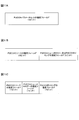
- FIG. 3 is a diagram illustrating a first determination example of the PUCCH format / structure according to the second aspect.
- the DL centric slot is associated with the short-term PUCCH, the UL centric slot, and the UL only slot in advance with the long-term PUCCH, but is not limited thereto.
- the user terminal may decide to use a short-term PUCCH.
- the slot type when the slot type is a UL centric slot, the user terminal may decide to use a long-term PUCCH.
- the slot type when the slot type is a UL only slot, the user terminal may decide to use a long-term PUCCH.
- PUCCH is not transmitted.
- a plurality of long-term PUCCHs with different time lengths shown in FIGS. 3B and 3C may be in different PUCCH formats, or may be defined in different time lengths in the same PUCCH format.
- the RS mapping pattern, RS sequence generation, scrambling method, UCI mapping pattern, etc. it is possible to reduce the mounting burden of the terminal.
- the RS mapping pattern, RS sequence generation, scrambling method, UCI mapping pattern, and the like to be different designs, the UCI is fed back in an appropriate PUCCH format suitable for each PUCCH transmission length. can do.
- the user terminal determines the PUCCH format / structure based on the instruction information indicating the PUCCH format / structure separately from the UL period information.
- the instruction information is information that explicitly indicates the PUCCH format / structure, and may be set by higher layer signaling and / or physical layer signaling.
- FIG. 4 is a diagram illustrating a second determination example of the PUCCH format / structure according to the second aspect.
- the user terminal determines whether to use a short-term PUCCH or a long-term PUCCH based on the instruction information indicating the PUCCH format / structure. It may be determined (may be switched).
- the user terminal determines that the short-term PUCCH, the first long-term PUCCH, or the second is based on the indication information indicating the PUCCH format / structure. Which long-term PUCCH is used may be determined (may be switched).
- the user terminal may determine to use a short-term PUCCH based on the slot type, as in the first determination example.
- the user terminal may determine the PUCCH format / structure based on UL period information (for example, slot type) and the instruction information.
- a partial field (for example, 2 bits) of DCI (DL assignment) for scheduling DL data can be used.
- the field can be read based on the UL period information of the slot transmitting the PUCCH. For example, if the slot is a DL centric slot with a short UL period, a short-term PUCCH is transmitted regardless of the value of the field, and if the slot is a UL centric or UL only with a long UL period, A short-term PUCCH or a long-term PUCCH can be transmitted based on the value of the field. Or you may specify the combination of UL period information and PUCCH format / structure of the slot which transmits PUCCH using the partial field (for example, 2 bits) of DCI (DL assignment).
- the user terminal determines the PUCCH format / structure based on the UCI type transmitted on the PUCCH.
- the UCI type indicates the contents of UCI, and may indicate at least one of A / N, scheduling request (SR), and channel state information (CSI) for the DL data channel, for example.
- the user terminal may determine the PUCCH format / structure based on information on the DL data channel that feeds back A / N (for example, the number of transmissions of the DL data channel).
- FIG. 5 is a diagram illustrating a third determination example of the PUCCH format / structure according to the second aspect.
- 5A and 5B illustrate an example in which the user terminal determines the PUCCH format / structure based on the comparison result between the DL data channel transmission count and a predetermined threshold N.
- the user terminal may be decided to use a short-term PUCCH for A / N transmission on the DL data channel.
- the user terminal You may decide to use PUCCH for a long time for A / N transmission.
- the predetermined threshold N is an integer of 1 or more, and may be determined in advance, or may be set by higher layer signaling and / or physical layer signaling.
- the DL data channel transmission count N may be set individually for each user terminal or may be set in common.
- the user terminal may determine to use a short-term PUCCH based on the slot type, as in the first determination example.
- the user terminal may determine the PUCCH format / structure based on UL period information (eg, slot type) and the number of DL data channel transmissions.
- a short-term PUCCH is used, so that it is possible to efficiently use UL resources.
- the user terminal determines the PUCCH format / structure based on the UCI payload (also referred to as information amount, number of information bits, etc.) transmitted on the PUCCH.
- FIG. 6 is a diagram illustrating a fourth determination example of the PUCCH format / structure according to the second aspect. 6A and 6B, an example will be described in which the user terminal determines the PUCCH format / structure based on the comparison result between the UCI payload and a predetermined threshold.
- the user terminal transmits a short-term transmission of the UCI. You may decide to use PUCCH.
- the user terminal transmits a long time to the UCI transmission. It may be decided to use the PUCCH of the period.
- the predetermined threshold for the payload is an integer of 1 or more, and may be determined in advance, or may be set by higher layer signaling and / or physical layer signaling. Further, the predetermined threshold value may be set individually for each user terminal or may be set in common. Further, the channel coding method, the interleaver method, the transmission power control method, and the like may be switched with the predetermined threshold. Accordingly, it is possible to realize appropriate performance according to the PUCCH format / structure that switches at the predetermined threshold.
- the user terminal may determine to use a short-term PUCCH based on the slot type, as in the first determination example.
- the user terminal may determine the PUCCH format / structure based on UL period information (eg, slot type) and UCI payload.
- a short-term PUCCH is used, so that efficient use of UL resources can be realized.
- the PUCCH resource used for PUCCH mapping and / or transmission may be determined by higher layer signaling (eg, system information or RRC signaling) and / or physical layer signaling (eg, DL control channel or DCI).
- higher layer signaling eg, system information or RRC signaling
- physical layer signaling eg, DL control channel or DCI.
- the PUCCH resource includes at least one of one or more frequency direction resource units (frequency resource units), one or more time direction resource units (time resource units), and one or more code resources.
- One or more frequency resource units (for example, resource block, PRB) constituting the PUCCH resource may be continuous in the frequency direction or discontinuous.
- one or more time resource units (for example, symbols) constituting the PUCCH resource may be continuous in the time direction or may be discontinuous.
- the one or more code resources constituting the PUCCH resource are codes (for example, orthogonal cover codes (OCC)) that are multiplied by signals multiplexed in the same frequency resource unit and / or time resource unit. (Spread code).
- codes for example, orthogonal cover codes (OCC)
- OCC orthogonal cover codes
- the PUCCH resource may be a set of one or more resource units (for example, resource block (RB), PRB) in the frequency direction in which one or more PUCCHs are mapped and / or transmitted.
- the one or more resource units may be continuous in the frequency direction or may be discontinuous.
- the user terminal includes a downlink control channel resource index, symbol index, RS (or beam) index, downlink data channel resource index, (starting downlink data channel transmission / reception) symbol index, RS (or beam) index, PUCCH resources may be determined based on at least one of the above. In this case, signaling for specifying the PUCCH resource can be made unnecessary. Or you may determine a PUCCH resource based on the value of the one part field of the control signal transmitted / received by a downlink control channel. In this case, flexible PUCCH resource allocation independent of control channel and data channel parameters is possible.
- the waveform used for PUCCH transmission may be determined by higher layer signaling (eg, system information or RRC signaling) and / or physical layer signaling (eg, DL control channel or DCI).
- the PUCCH waveform is, for example, OFDM (CP-OFDM) or DFT-s-OFDM, but is not limited thereto.
- the user terminal transmits the PUCCH format / structure (for example, information indicating the time length of the PUCCH (for example, a long period or a short period) or the number of symbols constituting the PUCCH), the UL period information, and / or
- the PUCCH waveform is determined based on at least one of the instruction information that explicitly indicates the PUCCH waveform and the PUSCH waveform (PUSCH waveform) separately from the PUCCH format / structure.
- FIG. 7 is a diagram illustrating an example of determining a PUCCH waveform according to the second mode.
- the PUCCH waveform is associated (linked) with information indicating the time length of the PUCCH (for example, a long period or a short period).
- the association between the PUCCH waveform and information indicating the time length of the PUCCH may be determined in advance in the specification, or may be set by higher layer signaling and / or physical layer signaling.
- the user terminal determines the PUCCH waveform to be a PUCCH waveform corresponding to the time length of PUCCH. For example, in the case of short-term PUCCH, the user terminal may determine the PUCCH waveform as OFDM. On the other hand, in the case of long-term PUCCH, the user terminal may determine the PUCCH waveform as DFT-s-OFDM.
- the PUCCH waveform may be associated with the number of symbols constituting the PUCCH.
- the association between the PUCCH waveform and the number of symbols constituting the PUCCH may be determined in advance in the specification, or may be set by higher layer signaling and / or physical layer signaling.
- the user terminal determines the PUCCH waveform to be a PUCCH waveform corresponding to the number of PUCCH symbols. For example, when the number of symbols is less than (or less than) a predetermined threshold value N, the user terminal may determine the PUCCH waveform as OFDM. On the other hand, when the number of symbols is equal to or greater than a predetermined threshold N (or exceeds N), the user terminal may determine the PUCCH waveform as DFT-s-OFDM.
- the PUCCH waveform may be determined based on instruction information that explicitly indicates the PUCCH waveform.
- the instruction information may be a bit field having a predetermined number of bits indicating OFDM or DFT-s-OFDM as shown in FIG. 7C.
- the user terminal determines the PUCCH waveform based on the instruction information regardless of the PUCCH format / structure. For example, the user terminal may determine DFT-s-OFDM as the PUCCH waveform when the indication information indicates DFT-s-OFDM even when the PUCCH is used for a short time. On the other hand, even when the user terminal uses long-term PUCCH, when the indication information indicates OFDM, the user terminal may determine the PUCCH waveform as OFDM.
- the PUCCH waveform may be determined based on the PUSCH waveform in the same slot or a predetermined slot.
- the user terminal determines the PUCCH waveform to be the same waveform as the PUSCH waveform in the same slot. For example, when the PUSCH waveform is DFT-s-OFDM, the user terminal may also determine the PUCCH waveform as DFT-s-OFDM. When the PUSCH waveform is OFDM, the user terminal may also determine the PUCCH waveform as OFDM.
- the transmission timing of PUCCH may be determined in advance by the specification, or determined by higher layer signaling (for example, system information or RRC signaling) and / or physical layer signaling (for example, DL control channel or DCI). May be.
- the user terminal may control a slot (transmission slot) for transmitting the PUCCH as the PUCCH timing.
- the transmission slot control may be applied to all slot types (eg, DL centric slot, UL centric slot, UL only slot) that support transmission of PUCCH.
- the user terminal may determine the A / N transmission slot of the PDSCH using the PUCCH after k slots (k ⁇ 0) from the PDSCH reception slot.
- a user terminal may determine the transmission slot of periodic CSI using PUCCH based on the period (for example, transmission period of periodic CSI) notified by higher layer signaling.
- the user terminal may control a symbol (transmission symbol) for transmitting the PUCCH in the transmission slot determined as described above as the PUCCH timing.
- the control of the transmission slot may be applied to a slot type having a long UL period, such as a UL centric slot or a UL only slot.
- FIG. 8 is a diagram illustrating an example of PUCCH timing according to the second aspect.
- PUCCH transmission slots are shown as UL timings 1 to 4.
- FIG. 8A to 8D show PUCCH transmission symbols in each transmission slot.
- the first symbol in the slot is shown in FIG. 8A, the second symbol from the beginning in FIG. 8B, the second symbol from the last in FIG. 8C, and the last symbol in FIG. 8D.
- the processing time on the network side (for example, a radio base station) can be lengthened.
- the processing time on the user terminal side can be lengthened.
- PUCCH transmission symbols (PUCCH timing in the slot) shown in FIGS. 8A to 8D are merely examples, and the present invention is not limited thereto. 8A to 8D, one transmission symbol is shown in each transmission slot, but a plurality of transmission symbols may be provided in each transmission slot. In the plurality of transmission symbols, PUCCHs of a plurality of user terminals may be transmitted, or a plurality of PUCCHs of a single user terminal may be transmitted.
- the user terminal may determine the PUCCH timing in the slot based on the UCI type.
- FIG. 9 is a diagram illustrating an example of determining the PUCCH timing in the slot according to the second mode.
- a plurality of transmission symbols here, the first symbol and the last symbol
- the present invention can also be applied to other slot types as appropriate.
- the user terminal may determine the head symbol as the PUCCH timing in the slot. Thereby, the second and subsequent symbols from the beginning can be used for PUSCH scheduling in the radio base station, and the time until scheduling of PUSCH to the user terminal can be shortened.
- SR scheduling request
- the user terminal may determine the final symbol as the PUCCH timing in the slot.
- the symbols from the beginning to the end can be used for the generation of A / N and / or CSI in the user terminal, and the time until the A / N and / or CSI is fed back to the radio base station Can be shortened.
- the PUCCH topology may be determined by higher layer signaling (eg, system information or RRC signaling) and / or physical layer signaling (eg, DL control channel or DCI). Or, unless otherwise specified, the user terminal transmits the PUCCH assuming that the PUCCH topology is the same as any or all of the downlink control channel, the downlink data channel, and the uplink data channel. May be.
- the neurology is communication parameters in the frequency direction and / or the time direction (for example, subcarrier spacing (SCS), symbol length, CP time length (CP length), slot time length ( Slot length), number of symbols per slot, filtering process, windowing process, etc.).
- SCS subcarrier spacing
- CP length CP time length
- Slot length slot time length
- number of symbols per slot filtering process, windowing process, etc.
- FIG. 10 is a diagram illustrating an example of the PUCCH pneumatic rhythm according to the second aspect.
- the case where the subcarrier spacing, the symbol length, and the slot length are different is shown as an example of the neurology.
- subcarrier spacing used for data PUSCH and / or PDSCH
- PUSCH and / or PDSCH subcarrier spacing used for data
- FIG. 10A PUCCH with the same subcarrier interval f 0 as the data is used, and in FIGS. 10B and 10C, PUCCH with a subcarrier interval 2f 0 that is twice the data is used. Since the subcarrier interval and the symbol length are inversely related, in FIGS. 10B and 10C, the PUCCH symbol length is 1 ⁇ 2 times the data symbol length. Thus, the same or different subcarrier intervals may be used for data in the same slot and PUCCH.
- the PUCCH subcarrier interval 2f 0 is twice the data subcarrier interval f 0 , so that two PUCCH timings 1 and 2 occur in one symbol of data.
- the user terminal may determine the PUCCH timing based on the neurology. Further, the user terminal may determine the PUCCH timing based on both the UCI type and the neurology.
- FIG. 11 is a diagram illustrating an example of DCI according to the second aspect.
- the DCI may be provided with a single designation field for designating one or more PUCCH parameters.
- a set (PUCCH parameter set) configured by at least one parameter included in the PUCCH format / structure, the PUCCH resource, the PUCCH topology, and the PUCCH timing may be designated.
- a maximum of 8 types of combinations of PUCCH parameter values in the PUCCH parameter set can be designated.
- the combination of PUCCH parameter values corresponding to each value of a single designated field may be determined by specifications or may be set by higher layer signaling.
- the DCI may be provided with a designation field for designating a single PUCCH parameter and a designation field for designating a plurality of PUCCH parameters.
- a designation field for designating a single PUCCH parameter and a designation field for designating a plurality of PUCCH parameters.
- a 2-bit designation field for designating a PUCCH resource and a 2-bit designation field for designating a combination of PUCCH numeric and PUCCH timing are provided.
- the DCI may be provided with a designation field for each PUCCH parameter.
- a designation field for designating a PUCCH resource For example, in FIG. 11C, a 1-bit designation field for designating a PUCCH resource, a 1-bit designation field for designating PUCCH topology, and a 1-bit designation field for designating PUCCH timing are provided.
- PUCCH parameter values (or combinations of PUCCH parameter values) corresponding to each value of each designated field may be determined by specifications or may be set by higher layer signaling. .
- the user terminal may determine whether to transmit UCI using PUSCH or PUCCH based on whether the PUSCH waveform and / or PUCCH transmission and PUSCH transmission overlap in time.
- FIG. 12 is a diagram illustrating an example of UCI transmission control according to the third mode.
- 12A and 12B show a case where the PUSCH waveform is DFT-s-OFDM and the PUCCH transmission and the PUSCH transmission overlap in time.
- a predetermined number of frequency resource units (for example, 6 PRBs) of the last symbol in the slot are secured as PUCCH resources.
- 6 PRBs frequency resource units
- PUCCH resources For example, 6 PRBs
- at least a part (for example, 2PRB) of the PUCCH resource reserved for the final symbol can be used for PUSCH.
- other than the PUCCH resource of the last symbol can be used for PUSCH.
- the user terminal may transmit UCI using the PUSCH ( piggybacked on PUSCH).
- the frequency resource unit reserved for PUCCH in the last symbol may be used for PUSCH.
- the user terminal may transmit UCI using the PUCCH. Good.
- the reserved PUCCH resources for example, 4PRB may be used for PUCCH transmission.
- FIG. 13 is a diagram showing another example of UCI transmission control according to the third mode.
- FIGS. 13A and 13B show a case where the PUSCH waveform is DFT-s-OFDM and the PUCCH transmission and the PUSCH transmission do not overlap in time (that is, when time division multiplexing is performed on different symbols).
- the PUCCH resource is reserved in the last symbol of the slot as in FIGS. 12A and 12B.
- the user terminal may transmit UCI using the PUSCH ( piggybacked on PUSCH).
- the user terminal can transmit UCI using the PUCCH. Good.
- the reserved PUCCH resources for example, 4 symbols
- SRS channeling sounding reference signal
- UCI and SRS may be multiplexed.
- UCI and SRS transmitted on PUCCH may be time-division multiplexed on different symbols in the same slot.
- UCI and SRS transmitted on PUCCH may be frequency division multiplexed on the same symbol in the same slot.
- the neurology used for SRS transmission (SRS topology) is associated (linked) with the topology of other channels in the same slot (for example, at least one of PUCCH, PDSCH, PUSCH, and PDCCH). May be set independently of the other channels. For example, it is suitable for frequency division multiplexing of PUCCH and SRS to make the SRS and PUCCH numerology the same.
- wireless communication system Wireless communication system
- the radio communication method according to each of the above aspects is applied.
- wireless communication method which concerns on each said aspect may be applied independently, respectively, and may be applied in combination.
- FIG. 14 is a diagram illustrating an example of a schematic configuration of the wireless communication system according to the present embodiment.
- carrier aggregation (CA) and / or dual connectivity (DC) in which a plurality of basic frequency blocks (component carriers) each having a system bandwidth (for example, 20 MHz) of the LTE system as one unit are applied. can do.
- the wireless communication system 1 is called SUPER 3G, LTE-A (LTE-Advanced), IMT-Advanced, 4G, 5G, FRA (Future Radio Access), NR (New Radio Access Technology), etc. Also good.
- a radio communication system 1 shown in FIG. 14 includes a radio base station 11 that forms a macro cell C1, and radio base stations 12a to 12c that are arranged in the macro cell C1 and form a small cell C2 that is narrower than the macro cell C1. .
- the user terminal 20 is arrange
- the user terminal 20 can be connected to both the radio base station 11 and the radio base station 12. It is assumed that the user terminal 20 uses the macro cell C1 and the small cell C2 that use different frequencies simultaneously by CA or DC. In addition, the user terminal 20 can apply CA or DC using a plurality of cells (CC) (for example, two or more CCs). Further, the user terminal can use the license band CC and the unlicensed band CC as a plurality of cells.
- CC cells
- the user terminal 20 can perform communication using time division duplex (TDD) or frequency division duplex (FDD) in each cell.
- TDD time division duplex
- FDD frequency division duplex
- the TDD cell and the FDD cell may be referred to as a TDD carrier (frame configuration type 2), an FDD carrier (frame configuration type 1), and the like, respectively.
- each cell (carrier) a single neurology may be applied, or a plurality of different neurology may be applied.
- Communication between the user terminal 20 and the radio base station 11 can be performed using a carrier having a relatively low frequency band (for example, 2 GHz) and a narrow bandwidth (referred to as an existing carrier or a legacy carrier).
- a carrier having a wide bandwidth in a relatively high frequency band for example, 3.5 GHz, 5 GHz, 30 to 70 GHz, etc.
- the same carrier as that between the base station 11 and the base station 11 may be used.
- the configuration of the frequency band used by each radio base station is not limited to this.
- a wired connection for example, an optical fiber compliant with CPRI (Common Public Radio Interface), an X2 interface, etc.
- a wireless connection It can be set as the structure to do.
- the radio base station 11 and each radio base station 12 are connected to the higher station apparatus 30 and connected to the core network 40 via the higher station apparatus 30.
- the upper station device 30 includes, for example, an access gateway device, a radio network controller (RNC), a mobility management entity (MME), and the like, but is not limited thereto.
- RNC radio network controller
- MME mobility management entity
- Each radio base station 12 may be connected to the higher station apparatus 30 via the radio base station 11.
- the radio base station 11 is a radio base station having a relatively wide coverage, and may be called a macro base station, an aggregation node, an eNB (eNodeB), a transmission / reception point, or the like.
- the radio base station 12 is a radio base station having local coverage, and includes a small base station, a micro base station, a pico base station, a femto base station, a HeNB (Home eNodeB), an RRH (Remote Radio Head), and transmission / reception. It may be called a point.
- the radio base stations 11 and 12 are not distinguished, they are collectively referred to as a radio base station 10.
- Each user terminal 20 is a terminal compatible with various communication methods such as LTE and LTE-A, and may include not only a mobile communication terminal but also a fixed communication terminal. Further, the user terminal 20 can perform inter-terminal communication (D2D) with other user terminals 20.
- D2D inter-terminal communication
- OFDMA orthogonal frequency division multiple access
- SC-FDMA single carrier-frequency division multiple access
- OFDMA is a multi-carrier transmission scheme that performs communication by dividing a frequency band into a plurality of narrow frequency bands (subcarriers) and mapping data to each subcarrier.
- SC-FDMA is a single-carrier transmission scheme that reduces interference between terminals by dividing the system bandwidth into bands consisting of one or continuous resource blocks for each terminal and using a plurality of terminals with mutually different bands. is there.
- the uplink and downlink radio access schemes are not limited to these combinations, and OFDMA may be used in the UL.
- a DL shared channel (PDSCH: Physical Downlink Shared Channel, also referred to as DL data channel) shared by each user terminal 20, a broadcast channel (PBCH: Physical Broadcast Channel), L1 / L2 A control channel or the like is used.
- PDSCH Physical Downlink Shared Channel
- PBCH Physical Broadcast Channel
- SIB System Information Block
- MIB Master Information Block
- L1 / L2 control channels include DL control channels (PDCCH (Physical Downlink Control Channel), EPDCCH (Enhanced Physical Downlink Control Channel)), PCFICH (Physical Control Format Indicator Channel), PHICH (Physical Hybrid-ARQ Indicator Channel), etc. .
- Downlink control information (DCI: Downlink Control Information) including scheduling information of PDSCH and PUSCH is transmitted by PDCCH.
- the number of OFDM symbols used for PDCCH is transmitted by PCFICH.
- the EPDCCH is frequency-division multiplexed with the PDSCH, and is used for transmission of DCI and the like as with the PDCCH.
- HARQ retransmission control information (ACK / NACK) for PUSCH can be transmitted by at least one of PHICH, PDCCH, and EPDCCH.
- a UL shared channel (PUSCH: Physical Uplink Shared Channel, also referred to as a UL data channel) shared by each user terminal 20, a UL control channel (PUCCH: Physical Uplink Control Channel), random An access channel (PRACH: Physical Random Access Channel) or the like is used.
- PUSCH Physical Uplink Shared Channel
- PUCCH Physical Uplink Control Channel
- PRACH Physical Random Access Channel
- User data and higher layer control information are transmitted by the PUSCH.
- Uplink control information (UCI) including at least one of retransmission control information (A / N), channel state information (CSI), and the like of a DL signal is transmitted by PUSCH or PUCCH.
- the PRACH can transmit a random access preamble for establishing a connection with a cell.
- FIG. 15 is a diagram illustrating an example of the overall configuration of the radio base station according to the present embodiment.
- the radio base station 10 includes a plurality of transmission / reception antennas 101, an amplifier unit 102, a transmission / reception unit 103, a baseband signal processing unit 104, a call processing unit 105, and a transmission path interface 106. Note that each of the transmission / reception antenna 101, the amplifier unit 102, and the transmission / reception unit 103 may be configured to include one or more.
- User data transmitted from the radio base station 10 to the user terminal 20 via the downlink is input from the higher station apparatus 30 to the baseband signal processing unit 104 via the transmission path interface 106.
- PDCP Packet Data Convergence Protocol
- RLC Radio Link Control
- MAC Medium Access
- Retransmission control for example, HARQ (Hybrid Automatic Repeat reQuest) transmission processing
- HARQ Hybrid Automatic Repeat reQuest
- the downlink control signal is also subjected to transmission processing such as channel coding and inverse fast Fourier transform, and is transferred to the transmission / reception unit 103.
- the transmission / reception unit 103 converts the baseband signal output by precoding for each antenna from the baseband signal processing unit 104 to a radio frequency band and transmits the converted signal.
- the radio frequency signal frequency-converted by the transmission / reception unit 103 is amplified by the amplifier unit 102 and transmitted from the transmission / reception antenna 101.
- the transmitter / receiver, the transmission / reception circuit, or the transmission / reception device can be configured based on common recognition in the technical field according to the present invention.
- the transmission / reception part 103 may be comprised as an integral transmission / reception part, and may be comprised from a transmission part and a receiving part.
- the radio frequency signal received by the transmission / reception antenna 101 is amplified by the amplifier unit 102.
- the transmission / reception unit 103 receives the UL signal amplified by the amplifier unit 102.
- the transmission / reception unit 103 converts the frequency of the received signal into a baseband signal and outputs it to the baseband signal processing unit 104.
- the baseband signal processing unit 104 performs Fast Fourier Transform (FFT) processing, Inverse Discrete Fourier Transform (IDFT) processing, error correction on UL data included in the input UL signal. Decoding, MAC retransmission control reception processing, RLC layer and PDCP layer reception processing are performed and transferred to the upper station apparatus 30 via the transmission path interface 106.
- the call processing unit 105 performs call processing such as communication channel setting and release, state management of the radio base station 10, and radio resource management.
- the transmission path interface 106 transmits and receives signals to and from the higher station apparatus 30 via a predetermined interface.
- the transmission path interface 106 transmits and receives (backhaul signaling) signals to and from the adjacent radio base station 10 via an interface between base stations (for example, an optical fiber compliant with CPRI (Common Public Radio Interface), X2 interface). Also good.
- CPRI Common Public Radio Interface
- X2 interface also good.
- the transmission / reception unit 103 transmits a DL signal (including at least one of a DL data signal, a DL control signal, and a DL reference signal) to the plurality of user terminals 20 having different nuemologies, and the plurality of user terminals 20 receives a UL signal (including at least one of a UL data signal, a UL control signal, and a UL reference signal).
- a DL signal including at least one of a DL data signal, a DL control signal, and a DL reference signal
- a UL signal including at least one of a UL data signal, a UL control signal, and a UL reference signal.
- the transmission / reception unit 103 receives UCI from the user terminal 20 using a UL data channel (for example, PUSCH) or a UL control channel (for example, PUCCH).
- the UCI includes at least one of ACK / NACK, CSI, and SR of a DL data channel (for example, PDSCH).
- the transmission / reception unit 103 transmits instruction information indicating a parameter (PUCCH parameter) related to the UL control channel.
- the parameters include PUCCH configuration (first aspect), PUCCH format / structure (second aspect), PUCCH structure (second aspect), PUCCH resource (second aspect), and PUCH waveform (second aspect).
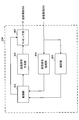
- FIG. 16 is a diagram illustrating an example of a functional configuration of the radio base station according to the present embodiment. Note that FIG. 16 mainly shows functional blocks of characteristic portions in the present embodiment, and the wireless base station 10 also has other functional blocks necessary for wireless communication. As illustrated in FIG. 16, the baseband signal processing unit 104 includes a control unit 301, a transmission signal generation unit 302, a mapping unit 303, a reception signal processing unit 304, and a measurement unit 305.
- the control unit 301 controls the entire radio base station 10.
- the control unit 301 includes, for example, DL signal generation by the transmission signal generation unit 302, DL signal mapping by the mapping unit 303, UL signal reception processing (for example, demodulation) by the reception signal processing unit 304, and measurement unit 305. Control the measurement.
- control unit 301 schedules the user terminal 20. Specifically, the control unit 301 may perform scheduling and / or retransmission control of the DL data channel and / or UL data channel based on the UCI from the user terminal 20.
- control unit 301 may determine to determine a parameter (PUCCH parameter) related to the UL control channel and transmit instruction information indicating the parameter.
- the parameters include PUCCH configuration (first mode), PUCCH format / structure (second mode), PUCCH structure (second mode), PUCCH resource (second mode), PUCH waveform (second mode). ), PUCCH timing (second aspect), and PUCCH pneumology (second aspect).
- the control unit 301 may control the reception signal processing unit 304 so as to perform reception processing of UCI from the user terminal 20 based on each UL control channel configuration.
- the control unit 301 can be configured by a controller, a control circuit, or a control device described based on common recognition in the technical field according to the present invention.
- the transmission signal generation unit 302 generates a DL signal (including a DL data signal, a DL control signal, and a DL reference signal) based on an instruction from the control unit 301, and outputs the DL signal to the mapping unit 303.
- the transmission signal generation unit 302 can be a signal generator, a signal generation circuit, or a signal generation device described based on common recognition in the technical field according to the present invention.
- the mapping unit 303 maps the DL signal generated by the transmission signal generation unit 302 to a predetermined radio resource based on an instruction from the control unit 301, and outputs the DL signal to the transmission / reception unit 103.
- the mapping unit 303 can be a mapper, a mapping circuit, or a mapping device described based on common recognition in the technical field according to the present invention.
- the reception signal processing unit 304 performs reception processing (for example, demapping, demodulation, decoding, etc.) on UL signals (for example, including UL data signals, UL control signals, and UL reference signals) transmitted from the user terminal 20. I do. Specifically, the reception signal processing unit 304 may output a reception signal or a signal after reception processing to the measurement unit 305. The reception signal processing unit 304 performs UCI reception processing based on the UL control channel configuration instructed from the control unit 301.
- the measurement unit 305 performs measurement on the received signal.
- the measurement part 305 can be comprised from the measuring device, measurement circuit, or measurement apparatus demonstrated based on common recognition in the technical field which concerns on this invention.
- the measurement unit 305 measures the UL channel quality based on, for example, the reception power (for example, RSRP (Reference Signal Received Power)) and / or the reception quality (for example, RSRQ (Reference Signal Received Quality)) of the UL reference signal. May be.
- the measurement result may be output to the control unit 301.
- FIG. 17 is a diagram illustrating an example of the overall configuration of the user terminal according to the present embodiment.
- the user terminal 20 includes a plurality of transmission / reception antennas 201 for MIMO transmission, an amplifier unit 202, a transmission / reception unit 203, a baseband signal processing unit 204, and an application unit 205.
- the radio frequency signals received by the plurality of transmission / reception antennas 201 are each amplified by the amplifier unit 202.
- Each transmitting / receiving unit 203 receives the DL signal amplified by the amplifier unit 202.
- the transmission / reception unit 203 converts the frequency of the received signal into a baseband signal and outputs it to the baseband signal processing unit 204.
- the baseband signal processing unit 204 performs FFT processing, error correction decoding, retransmission control reception processing, and the like on the input baseband signal.
- the DL data is transferred to the application unit 205.
- the application unit 205 performs processing related to layers higher than the physical layer and the MAC layer. Broadcast information is also transferred to the application unit 205.
- UL data is input from the application unit 205 to the baseband signal processing unit 204.
- the baseband signal processing unit 204 performs retransmission control transmission processing (for example, HARQ transmission processing), channel coding, rate matching, puncturing, discrete Fourier transform (DFT) processing, IFFT processing, and the like. Are transferred to each transmitting / receiving unit 203. Also for UCI, at least one of channel coding, rate matching, puncturing, DFT processing, and IFFT processing is performed and transferred to each transmission / reception section 203.
- the transmission / reception unit 203 converts the baseband signal output from the baseband signal processing unit 204 into a radio frequency band and transmits it.
- the radio frequency signal frequency-converted by the transmission / reception unit 203 is amplified by the amplifier unit 202 and transmitted from the transmission / reception antenna 201.
- the transmission / reception unit 203 receives a DL signal (including a DL data signal, a DL control signal, and a DL reference signal) of the neurology set in the user terminal 20 and receives the UL signal (UL data signal) of the neurology. , UL control signal and UL reference signal).
- a DL signal including a DL data signal, a DL control signal, and a DL reference signal
- the UL signal (UL data signal) of the neurology. , UL control signal and UL reference signal).
- the transmission / reception unit 203 transmits UCI to the radio base station 10 using a UL data channel (for example, PUSCH) or a UL control channel (for example, PUCCH). Further, the transmission / reception unit 203 receives instruction information indicating the PUCCH parameter.
- a UL data channel for example, PUSCH
- a UL control channel for example, PUCCH
- the transmission / reception unit 203 can be a transmitter / receiver, a transmission / reception circuit, or a transmission / reception device described based on common recognition in the technical field according to the present invention. Further, the transmission / reception unit 203 may be configured as an integral transmission / reception unit, or may be configured from a transmission unit and a reception unit.
- FIG. 18 is a diagram illustrating an example of a functional configuration of the user terminal according to the present embodiment. Note that FIG. 18 mainly shows functional blocks of characteristic portions in the present embodiment, and the user terminal 20 also has other functional blocks necessary for wireless communication. As illustrated in FIG. 18, the baseband signal processing unit 204 included in the user terminal 20 includes a control unit 401, a transmission signal generation unit 402, a mapping unit 403, a reception signal processing unit 404, and a measurement unit 405. I have.
- the control unit 401 controls the entire user terminal 20. For example, the control unit 401 controls generation of the UL signal by the transmission signal generation unit 402, mapping of the UL signal by the mapping unit 403, reception processing of the DL signal by the reception signal processing unit 404, and measurement by the measurement unit 405.
- the control unit 401 controls the UL control channel used for UCI transmission from the user terminal 20 based on an explicit instruction from the radio base station 10 or an implicit determination in the user terminal 20 (second mode). .
- control unit 401 includes information indicating the time length of the UL period, instruction information from the radio base station 10, the UCI payload, and the UCI including retransmission control information for downlink (DL) data.
- the PUCCH format / structure (or at least one PUCCH parameter included in the PUCCH format / structure) may be determined based on at least one of the number of DL data transmissions.
- control unit 401 may determine a PUCCH resource based on control information from the radio base station 10 and / or an implicit determination in the user terminal 20.
- control unit 401 determines a PUCCH waveform based on at least one of information indicating the PUCCH time length, the number of PUCCH symbols, instruction information from the radio base station 10, and a PUSCH waveform. Also good.
- control unit 401 determines at least one PUCCH timing (or at least one PUCCH included in the PUCCH timing) based on at least one of the instruction information from the radio base station 10, the contents of the UCI, and the PUCCH pneumatics. Parameter) may be determined.
- control unit 401 may determine the PUCCH topology based on the instruction information from the radio base station 10.
- control unit 401 controls UCI transmission in the slot to which the PUSCH is assigned (third mode). Specifically, the control unit 401 determines whether to use the PUSCH or the PUCCH to transmit the UCI based on whether the PUSCH waveform and / or the PUCCH transmission and the PUSCH transmission overlap in time. You may decide.
- control unit 401 may control the UCI transmission in the slot to which the SRS is assigned (fourth mode).
- the control unit 401 can be configured by a controller, a control circuit, or a control device described based on common recognition in the technical field according to the present invention.
- the transmission signal generation unit 402 generates a UL signal (including UL data signal, UL control signal, UL reference signal, UCI) based on an instruction from the control unit 401 (for example, encoding, rate matching, puncturing, modulation) And the like are output to the mapping unit 403.
- the transmission signal generation unit 402 may be a signal generator, a signal generation circuit, or a signal generation device described based on common recognition in the technical field according to the present invention.
- the mapping unit 403 maps the UL signal generated by the transmission signal generation unit 402 to a radio resource based on an instruction from the control unit 401, and outputs it to the transmission / reception unit 203.
- the mapping unit 403 may be a mapper, a mapping circuit, or a mapping device described based on common recognition in the technical field according to the present invention.
- the reception signal processing unit 404 performs reception processing (for example, demapping, demodulation, decoding, etc.) on the DL signal (DL data signal, scheduling information, DL control signal, DL reference signal).
- the reception signal processing unit 404 outputs information received from the radio base station 10 to the control unit 401.
- the reception signal processing unit 404 outputs, for example, broadcast information, system information, higher layer control information by higher layer signaling such as RRC signaling, physical layer control information (L1 / L2 control information), and the like to the control unit 401.
- the received signal processing unit 404 can be configured by a signal processor, a signal processing circuit, or a signal processing device described based on common recognition in the technical field according to the present invention. Further, the reception signal processing unit 404 can constitute a reception unit according to the present invention.
- the measurement unit 405 measures the channel state based on a reference signal (for example, CSI-RS) from the radio base station 10 and outputs the measurement result to the control unit 401. Note that the channel state measurement may be performed for each CC.
- a reference signal for example, CSI-RS
- the measuring unit 405 can be composed of a signal processor, a signal processing circuit or a signal processing device, and a measuring device, a measurement circuit or a measuring device which are explained based on common recognition in the technical field according to the present invention.
- each functional block may be realized by one device physically and / or logically coupled, and two or more devices physically and / or logically separated may be directly and / or indirectly. (For example, wired and / or wireless) and may be realized by these plural devices.
- a radio base station, a user terminal, etc. in an embodiment of the present invention may function as a computer that performs processing of the radio communication method of the present invention.
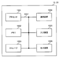
- FIG. 19 is a diagram illustrating an example of a hardware configuration of a radio base station and a user terminal according to an embodiment of the present invention.
- the wireless base station 10 and the user terminal 20 described above may be physically configured as a computer device including a processor 1001, a memory 1002, a storage 1003, a communication device 1004, an input device 1005, an output device 1006, a bus 1007, and the like. Good.
- the term “apparatus” can be read as a circuit, a device, a unit, or the like.
- the hardware configurations of the radio base station 10 and the user terminal 20 may be configured to include one or a plurality of each device illustrated in the figure, or may be configured not to include some devices.
- processor 1001 may be implemented by one or more chips.
- each function in the radio base station 10 and the user terminal 20 reads predetermined software (program) on hardware such as the processor 1001 and the memory 1002, so that the processor 1001 performs computation and communication by the communication device 1004. It is realized by controlling the reading and / or writing of data in the memory 1002 and the storage 1003.
- the processor 1001 controls the entire computer by operating an operating system, for example.
- the processor 1001 may be configured by a central processing unit (CPU) including an interface with peripheral devices, a control device, an arithmetic device, a register, and the like.
- CPU central processing unit
- the baseband signal processing unit 104 (204) and the call processing unit 105 described above may be realized by the processor 1001.
- the processor 1001 reads programs (program codes), software modules, data, and the like from the storage 1003 and / or the communication device 1004 to the memory 1002, and executes various processes according to these.
- programs program codes
- software modules software modules
- data data
- the like data
- the control unit 401 of the user terminal 20 may be realized by a control program stored in the memory 1002 and operated by the processor 1001, and may be realized similarly for other functional blocks.
- the memory 1002 is a computer-readable recording medium such as a ROM (Read Only Memory), an EPROM (Erasable Programmable ROM), an EEPROM (Electrically EPROM), a RAM (Random Access Memory), or any other suitable storage medium. It may be configured by one.
- the memory 1002 may be called a register, a cache, a main memory (main storage device), or the like.
- the memory 1002 can store programs (program codes), software modules, and the like that can be executed to implement the wireless communication method according to an embodiment of the present invention.
- the storage 1003 is a computer-readable recording medium such as a flexible disk, a floppy (registered trademark) disk, a magneto-optical disk (for example, a compact disk (CD-ROM (Compact Disc ROM)), a digital versatile disk, Blu-ray® disk), removable disk, hard disk drive, smart card, flash memory device (eg, card, stick, key drive), magnetic stripe, database, server, or other suitable storage medium It may be constituted by.
- the storage 1003 may be referred to as an auxiliary storage device.
- the communication device 1004 is hardware (transmission / reception device) for performing communication between computers via a wired and / or wireless network, and is also referred to as a network device, a network controller, a network card, a communication module, or the like.
- the communication device 1004 includes, for example, a high-frequency switch, a duplexer, a filter, a frequency synthesizer, etc., in order to realize frequency division duplex (FDD) and / or time division duplex (TDD). It may be configured.
- FDD frequency division duplex
- TDD time division duplex
- the transmission / reception antenna 101 (201), the amplifier unit 102 (202), the transmission / reception unit 103 (203), the transmission path interface 106, and the like described above may be realized by the communication device 1004.
- the input device 1005 is an input device (for example, a keyboard, a mouse, a microphone, a switch, a button, a sensor, etc.) that accepts an input from the outside.
- the output device 1006 is an output device (for example, a display, a speaker, an LED (Light Emitting Diode) lamp, etc.) that performs output to the outside.
- the input device 1005 and the output device 1006 may have an integrated configuration (for example, a touch panel).
- each device such as the processor 1001 and the memory 1002 is connected by a bus 1007 for communicating information.
- the bus 1007 may be configured with a single bus or may be configured with different buses between apparatuses.
- the radio base station 10 and the user terminal 20 include a microprocessor, a digital signal processor (DSP), an ASIC (Application Specific Integrated Circuit), a PLD (Programmable Logic Device), an FPGA (Field Programmable Gate Array), and the like. It may be configured including hardware, and a part or all of each functional block may be realized by the hardware. For example, the processor 1001 may be implemented by at least one of these hardware.
- DSP digital signal processor
- ASIC Application Specific Integrated Circuit
- PLD Programmable Logic Device
- FPGA Field Programmable Gate Array
- the channel and / or symbol may be a signal (signaling).
- the signal may be a message.
- the reference signal may be abbreviated as RS (Reference Signal), and may be referred to as a pilot, a pilot signal, or the like depending on an applied standard.
- a component carrier CC: Component Carrier
- CC Component Carrier
- the radio frame may be configured with one or a plurality of periods (frames) in the time domain.
- Each of the one or more periods (frames) constituting the radio frame may be referred to as a subframe.
- a subframe may be composed of one or more slots in the time domain.
- the subframe may have a fixed time length (eg, 1 ms) that does not depend on the neurology.
- the slot may be configured with one or a plurality of symbols (OFDM (Orthogonal Frequency Division Multiplexing) symbol, SC-FDMA (Single Carrier Frequency Division Multiple Access) symbol, etc.) in the time domain). Further, the slot may be a time unit based on the numerology.
- the slot may include a plurality of mini slots. Each minislot may be composed of one or more symbols in the time domain. The minislot may also be called a subslot.
- Radio frame, subframe, slot, minislot, and symbol all represent time units when transmitting signals. Different names may be used for the radio frame, subframe, slot, minislot, and symbol.
- one subframe may be called a transmission time interval (TTI)
- TTI transmission time interval
- a plurality of consecutive subframes may be called a TTI
- TTI slot or one minislot
- a unit representing TTI may be called a slot, a minislot, or the like instead of a subframe.
- TTI means, for example, a minimum time unit for scheduling in wireless communication.
- a radio base station performs scheduling for assigning radio resources (frequency bandwidth, transmission power, etc. that can be used in each user terminal) to each user terminal in units of TTI.
- the definition of TTI is not limited to this.
- the TTI may be a transmission time unit of a channel-encoded data packet (transport block), a code block, and / or a code word, or may be a processing unit such as scheduling or link adaptation.
- a time interval for example, the number of symbols
- a transport block, a code block, and / or a code word is actually mapped may be shorter than the TTI.
- one or more TTIs may be the minimum scheduling unit. Further, the number of slots (the number of mini-slots) constituting the minimum time unit of the scheduling may be controlled.
- a TTI having a time length of 1 ms may be called a normal TTI (TTI in LTE Rel. 8-12), a normal TTI, a long TTI, a normal subframe, a normal subframe, or a long subframe.
- a TTI shorter than a normal TTI may be called a shortened TTI, a short TTI, a partial TTI (partial or fractional TTI), a shortened subframe, a short subframe, a minislot, or a subslot.
- a long TTI (eg, normal TTI, subframe, etc.) may be read as a TTI having a time length exceeding 1 ms, and a short TTI (eg, shortened TTI) is less than the TTI length of the long TTI and 1 ms. It may be replaced with a TTI having the above TTI length.
- a resource block is a resource allocation unit in the time domain and the frequency domain, and may include one or a plurality of continuous subcarriers (subcarriers) in the frequency domain. Further, the RB may include one or a plurality of symbols in the time domain, and may have a length of 1 slot, 1 mini slot, 1 subframe, or 1 TTI. One TTI and one subframe may each be composed of one or a plurality of resource blocks.
- One or more RBs include physical resource blocks (PRB), sub-carrier groups (SCG), resource element groups (REG), PRB pairs, RB pairs, etc. May be called.
- the resource block may be composed of one or a plurality of resource elements (RE: Resource Element).
- RE Resource Element
- 1RE may be a radio resource region of 1 subcarrier and 1 symbol.
- the structure of the above-described radio frame, subframe, slot, minislot, symbol, etc. is merely an example.
- the number of subframes included in a radio frame, the number of slots per subframe or radio frame, the number of minislots included in the slot, the number of symbols and RBs included in the slot or minislot, and the RB The number of subcarriers, the number of symbols in the TTI, the symbol length, the cyclic prefix (CP) length, and the like can be variously changed.
- information, parameters, and the like described in this specification may be represented by absolute values, may be represented by relative values from a predetermined value, or may be represented by other corresponding information.
- the radio resource may be indicated by a predetermined index.
- mathematical formulas and the like using these parameters may differ from those explicitly disclosed herein.
- PUCCH Physical Uplink Control Channel
- PDCCH Physical Downlink Control Channel
- information elements can be identified by any suitable name, so the various channels and information elements assigned to them.
- the name is not limiting in any way.
- information, signals, etc. can be output from the upper layer to the lower layer and / or from the lower layer to the upper layer.
- Information, signals, and the like may be input / output via a plurality of network nodes.
- the input / output information, signals, etc. may be stored in a specific location (for example, a memory), or may be managed by a management table. Input / output information, signals, and the like can be overwritten, updated, or added. The output information, signals, etc. may be deleted. Input information, signals, and the like may be transmitted to other devices.
- information notification includes physical layer signaling (eg, downlink control information (DCI), uplink control information (UCI)), upper layer signaling (eg, RRC (Radio Resource Control) signaling), It may be implemented by broadcast information (Master Information Block (MIB), System Information Block (SIB), etc.), MAC (Medium Access Control) signaling), other signals, or a combination thereof.
- DCI downlink control information
- UCI uplink control information
- RRC Radio Resource Control
- MIB Master Information Block
- SIB System Information Block
- MAC Medium Access Control
- the physical layer signaling may be referred to as L1 / L2 (Layer 1 / Layer 2) control information (L1 / L2 control signal), L1 control information (L1 control signal), or the like.
- the RRC signaling may be referred to as an RRC message, and may be, for example, an RRC connection setup (RRCConnectionSetup) message, an RRC connection reconfiguration (RRCConnectionReconfiguration) message, or the like.
- the MAC signaling may be notified by, for example, a MAC control element (MAC CE (Control Element)).
- notification of predetermined information is not limited to explicitly performed, but implicitly (for example, by not performing notification of the predetermined information or another (By notification of information).
- the determination may be performed by a value represented by 1 bit (0 or 1), or may be performed by a boolean value represented by true or false.
- the comparison may be performed by numerical comparison (for example, comparison with a predetermined value).
- software, instructions, information, etc. may be transmitted / received via a transmission medium.
- software can use websites, servers using wired technology (coaxial cable, fiber optic cable, twisted pair, digital subscriber line (DSL), etc.) and / or wireless technology (infrared, microwave, etc.) , Or other remote sources, these wired and / or wireless technologies are included within the definition of transmission media.
- system and “network” used in this specification are used interchangeably.
- base station BS
- radio base station eNB
- gNB gNodeB
- cell gNodeB
- cell group a base station
- carrier a base station
- component carrier a base station
- a base station may also be called in terms such as a fixed station, NodeB, eNodeB (eNB), access point, transmission point, reception point, femtocell, and small cell.
- the base station can accommodate one or a plurality of (for example, three) cells (also called sectors). If the base station accommodates multiple cells, the entire coverage area of the base station can be partitioned into multiple smaller areas, each smaller area being a base station subsystem (eg, an indoor small base station (RRH: The term “cell” or “sector” refers to part or all of the coverage area of a base station and / or base station subsystem that provides communication service in this coverage. Point to.
- RRH indoor small base station
- MS mobile station
- UE user equipment
- terminal may be used interchangeably.
- a base station may also be called in terms such as a fixed station, NodeB, eNodeB (eNB), access point, transmission point, reception point, femtocell, and small cell.
- NodeB NodeB
- eNodeB eNodeB
- access point transmission point
- reception point femtocell
- small cell small cell
- a mobile station is defined by those skilled in the art as a subscriber station, mobile unit, subscriber unit, wireless unit, remote unit, mobile device, wireless device, wireless communication device, remote device, mobile subscriber station, access terminal, mobile terminal, wireless It may also be called terminal, remote terminal, handset, user agent, mobile client, client or some other suitable terminology.
- the radio base station in this specification may be read by the user terminal.
- each aspect / embodiment of the present invention may be applied to a configuration in which communication between a radio base station and a user terminal is replaced with communication between a plurality of user terminals (D2D: Device-to-Device).
- the user terminal 20 may have a function that the wireless base station 10 has.
- words such as “up” and “down” may be read as “side”.
- the uplink channel may be read as a side channel.
- a user terminal in this specification may be read by a radio base station.
- the wireless base station 10 may have a function that the user terminal 20 has.
- the specific operation assumed to be performed by the base station may be performed by the upper node in some cases.
- various operations performed for communication with a terminal may be performed by one or more network nodes other than the base station and the base station (for example, It is obvious that this can be done by MME (Mobility Management Entity), S-GW (Serving-Gateway), etc., but not limited thereto) or a combination thereof.
- MME Mobility Management Entity
- S-GW Serving-Gateway
- each aspect / embodiment described in this specification may be used alone, in combination, or may be switched according to execution.
- the order of the processing procedures, sequences, flowcharts, and the like of each aspect / embodiment described in this specification may be changed as long as there is no contradiction.
- the methods described herein present the elements of the various steps in an exemplary order and are not limited to the specific order presented.
- Each aspect / embodiment described herein includes LTE (Long Term Evolution), LTE-A (LTE-Advanced), LTE-B (LTE-Beyond), SUPER 3G, IMT-Advanced, 4G (4th generation mobile). communication system), 5G (5th generation mobile communication system), FRA (Future Radio Access), New-RAT (Radio Access Technology), NR (New Radio), NX (New radio access), FX (Future generation radio access), GSM (registered trademark) (Global System for Mobile communications), CDMA2000, UMB (Ultra Mobile Broadband), IEEE 802.11 (Wi-Fi (registered trademark)), IEEE 802.16 (WiMAX (registered trademark)), IEEE 802 .20, UWB (Ultra-WideBand), Bluetooth (registered trademark), The present invention may be applied to a system using other appropriate wireless communication methods and / or a next generation system extended based on these.
- the phrase “based on” does not mean “based only on”, unless expressly specified otherwise. In other words, the phrase “based on” means both “based only on” and “based at least on.”
- any reference to elements using designations such as “first”, “second”, etc. as used herein does not generally limit the amount or order of those elements. These designations can be used herein as a convenient way to distinguish between two or more elements. Thus, reference to the first and second elements does not mean that only two elements can be employed or that the first element must precede the second element in some way.
- determining may encompass a wide variety of actions. For example, “determination” means calculating, computing, processing, deriving, investigating, looking up (eg, table, database or other data). It may be considered to “judge” (search in structure), ascertaining, etc.
- “determination (decision)” includes receiving (for example, receiving information), transmitting (for example, transmitting information), input (input), output (output), access ( accessing) (e.g., accessing data in memory), etc. may be considered to be “determining”. Also, “determination” is considered to be “determination (resolving)”, “selecting”, “choosing”, “establishing”, “comparing”, etc. Also good. That is, “determination (determination)” may be regarded as “determination (determination)” of some operation.
- connection refers to any direct or indirect connection between two or more elements or By coupling, it can include the presence of one or more intermediate elements between two elements that are “connected” or “coupled” to each other.
- the coupling or connection between the elements may be physical, logical, or a combination thereof.
- connection may be read as “access”.
- the two elements are radio frequency by using one or more wires, cables and / or printed electrical connections, and as some non-limiting and non-inclusive examples It can be considered to be “connected” or “coupled” to each other, such as by using electromagnetic energy having wavelengths in the region, microwave region, and / or light (both visible and invisible) region.
Landscapes
- Engineering & Computer Science (AREA)
- Signal Processing (AREA)
- Computer Networks & Wireless Communication (AREA)
- Mobile Radio Communication Systems (AREA)
Abstract
Description
第1の態様では、UL制御チャネル(以下、PUCCHと略する)の構成(configuration)について説明する。PUCCHの構成(PUCCH構成)は、PUCCHの生成処理、送信処理、受信処理の少なくとも一つに必要な構成を定めたものである。
次に、ユーザ端末が、UL期間の時間長が異なる複数のスロットの少なくとも一つでUCIを送信する場合において、当該UCIの送信に用いるPUCCHを制御する動作について説明する。ユーザ端末は、無線基地局からの明示的指示又はユーザ端末による黙示的決定に基づいて、当該PUCCHを制御する。
PUCCHフォーマット/構造は、上位レイヤシグナリング(例えば、システム情報又はRRCシグナリング)及び/又は物理レイヤシグナリング(例えば、DL制御チャネル又はDCI)により決定されてもよい。
第1の決定例では、ユーザ端末は、上記UL期間情報に基づいて、PUCCHフォーマット/構造を決定する。ここで、UL期間情報は、例えば、DLオンリースロット、DLセントリックスロット、ULオンリースロット、ULセントリックスロットなどを示すスロットタイプであってもよい。
第2の決定例では、ユーザ端末は、上記UL期間情報とは別にPUCCHフォーマット/構造を指示する指示情報に基づいて、PUCCHフォーマット/構造を決定する。当該指示情報は、PUCCHフォーマット/構造を明示的に指示する情報であり、上位レイヤシグナリング及び/又は物理レイヤシグナリングにより設定されてもよい。
第3の決定例では、ユーザ端末は、PUCCHで送信するUCIタイプに基づいて、PUCCHフォーマット/構造を決定する。当該UCIタイプは、UCIの内容を示し、例えば、DLデータチャネルに対するA/N、スケジューリング要求(SR)、チャネル状態情報(CSI)の少なくとも一つを示してもよい。
第4の決定例では、ユーザ端末は、PUCCHで送信するUCIのペイロード(情報量、情報ビット数等ともいう)に基づいて、PUCCHフォーマット/構造を決定する。
PUCCHのマッピング及び/又は送信に用いられるPUCCHリソースは、上位レイヤシグナリング(例えば、システム情報又はRRCシグナリング)及び/又は物理レイヤシグナリング(例えば、DL制御チャネル又はDCI)により決定されてもよい。
PUCCHの送信に用いられる波形(PUCCH波形)は、上位レイヤシグナリング(例えば、システム情報又はRRCシグナリング)及び/又は物理レイヤシグナリング(例えば、DL制御チャネル又はDCI)により決定されてもよい。PUCCH波形は、例えば、OFDM(CP-OFDM)、又は、DFT-s-OFDMなどであるが、これに限られない。
PUCCHの送信タイミング(PUCCHタイミング)は、予め仕様で定められていてもよいし、上位レイヤシグナリング(例えば、システム情報又はRRCシグナリング)及び/又は物理レイヤシグナリング(例えば、DL制御チャネル又はDCI)により決定されてもよい。
PUCCHのニューメロロジー(PUCCHニューメロロジー)は、上位レイヤシグナリング(例えば、システム情報又はRRCシグナリング)及び/又は物理レイヤシグナリング(例えば、DL制御チャネル又はDCI)により決定されてもよい。または、特に指示がない限り、ユーザ端末は、PUCCHニューメロロジーが下り制御チャネル、下りデータチャネル、上りデータチャネルのいずれか又はすべてのニューメロロジーと同じであると想定して、PUCCHを送信してもよい。
上記PUCCHフォーマット/構造、PUCCHリソース、PUCCHニューメロロジー、PUCCHタイミングの少なくとも一つは、動的に指定されることが想定されるため、どのようにDCIを構成するかが問題となる。そこで、以上のようなPUCCHパラメータを指示するDCIについて説明する。
第3の態様では、PUSCHが割り当てられたスロットにおけるUCIの送信制御について説明する。ユーザ端末は、PUSCH波形、及び/又は、PUCCH送信とPUSCH送信とが時間的に重複するか否かに基づいて、PUSCH又はPUCCHのいずれを用いてUCIを送信するかを決定してもよい。
その他の態様では、チャネル状態のサウンディング用参照信号(SRS:Sounding Reference Signal)が送信されるスロットにおけるUCIの送信制御について説明する。SRSの送信は、上位レイヤシグナリングにより設定されてもよいし、物理レイヤシグナリングにより指定されてもよい。上位レイヤシグナリングの場合、SRSは、例えば、最終シンボル、又は、スロットの最後にギャップ期間が規定される場合は当該ギャップ期間に最も近い位置に設定されてもよい。
以下、本実施の形態に係る無線通信システムの構成について説明する。この無線通信システムでは、上記各態様に係る無線通信方法が適用される。なお、上記各態様に係る無線通信方法は、それぞれ単独で適用されてもよいし、組み合わせて適用されてもよい。
図15は、本実施の形態に係る無線基地局の全体構成の一例を示す図である。無線基地局10は、複数の送受信アンテナ101と、アンプ部102と、送受信部103と、ベースバンド信号処理部104と、呼処理部105と、伝送路インターフェース106とを備えている。なお、送受信アンテナ101、アンプ部102、送受信部103は、それぞれ1つ以上を含むように構成されてもよい。
図17は、本実施の形態に係るユーザ端末の全体構成の一例を示す図である。ユーザ端末20は、MIMO伝送のための複数の送受信アンテナ201と、アンプ部202と、送受信部203と、ベースバンド信号処理部204と、アプリケーション部205と、を備えている。
なお、上記実施形態の説明に用いたブロック図は、機能単位のブロックを示している。これらの機能ブロック(構成部)は、ハードウェア及び/又はソフトウェアの任意の組み合わせによって実現される。また、各機能ブロックの実現手段は特に限定されない。すなわち、各機能ブロックは、物理的及び/又は論理的に結合した1つの装置により実現されてもよいし、物理的及び/又は論理的に分離した2つ以上の装置を直接的及び/又は間接的に(例えば、有線及び/又は無線)で接続し、これら複数の装置により実現されてもよい。
なお、本明細書で説明した用語及び/又は本明細書の理解に必要な用語については、同一の又は類似する意味を有する用語と置き換えてもよい。例えば、チャネル及び/又はシンボルは信号(シグナリング)であってもよい。また、信号はメッセージであってもよい。参照信号は、RS(Reference Signal)と略称することもでき、適用される標準によってパイロット(Pilot)、パイロット信号などと呼ばれてもよい。また、コンポーネントキャリア(CC:Component Carrier)は、セル、周波数キャリア、キャリア周波数などと呼ばれてもよい。
Claims (6)
- UL期間の時間長が異なる複数のスロットの少なくとも一つで上りリンク制御情報(UCI)を送信する送信部と、
前記UCIの送信を制御部する制御部と、を具備し、
前記制御部は、無線基地局からの明示的指示又はユーザ端末による黙示的決定に基づいて、前記UCIの送信に用いる上りリンク(UL)制御チャネルを制御することを特徴とするユーザ端末。 - 前記制御部は、前記UL期間の時間長を示す情報と、無線基地局からの指示情報と、前記UCIのペイロードと、前記UCIが下りリンク(DL)データに対する再送制御情報を含む場合における前記DLデータの送信回数との少なくとも一つに基づいて、前記UL制御チャネルの時間長を示す情報と、前記UL制御チャネルのペイロードと、前記UL制御チャネルのシンボル数と、前記UL制御チャネルのリソースブロック数との少なくとも一つを決定することを特徴とする請求項1に記載のユーザ端末。
- 前記制御部は、前記UL制御チャネルの時間長を示す情報と、前記UL制御チャネルのシンボル数と、無線基地局からの指示情報と、ULデータチャネルの波形との少なくとも一つに基づいて、前記UL制御チャネルの波形を決定することを特徴とする請求項1又は請求項2に記載のユーザ端末。
- 前記制御部は、無線基地局からの指示情報と、前記UCIの内容と、前記UL制御チャネルのニューメロロジーとの少なくとも一つに基づいて、前記UL制御チャネルを送信するスロット及び/又はシンボルを決定することを特徴とする請求項1から請求項3のいずれかに記載のユーザ端末。
- 前記制御部は、無線基地局からの指示情報に基づいて、前記UL制御チャネルのニューメロロジーを決定することを特徴とする請求項1から請求項4のいずれかに記載のユーザ端末。
- ユーザ端末において、スロット内のUL期間の時間長が異なる複数のスロットの少なくとも一つで上りリンク制御情報(UCI)を送信する工程と、
無線基地局からの明示的指示又はユーザ端末による黙示的決定に基づいて、前記UCIの送信に用いる上りリンク(UL)制御チャネルを制御する工程と
を有することを特徴とする無線通信方法。
Priority Applications (5)
| Application Number | Priority Date | Filing Date | Title |
|---|---|---|---|
| JP2018549010A JP7074681B2 (ja) | 2016-11-01 | 2017-10-31 | 端末、無線通信方法、基地局及びシステム |
| MX2019005083A MX2019005083A (es) | 2016-11-01 | 2017-10-31 | Terminal de usuario y metodo de radiocomunicaciones. |
| EP17866780.4A EP3537796B1 (en) | 2016-11-01 | 2017-10-31 | User terminal and radio communications method |
| US16/346,270 US11528729B2 (en) | 2016-11-01 | 2017-10-31 | User terminal and radio communication method |
| CN201780081211.4A CN110169164B (zh) | 2016-11-01 | 2017-10-31 | 用户终端及无线通信方法 |
Applications Claiming Priority (2)
| Application Number | Priority Date | Filing Date | Title |
|---|---|---|---|
| JP2016-214704 | 2016-11-01 | ||
| JP2016214704 | 2016-11-01 |
Publications (1)
| Publication Number | Publication Date |
|---|---|
| WO2018084137A1 true WO2018084137A1 (ja) | 2018-05-11 |
Family
ID=62076131
Family Applications (1)
| Application Number | Title | Priority Date | Filing Date |
|---|---|---|---|
| PCT/JP2017/039286 Ceased WO2018084137A1 (ja) | 2016-11-01 | 2017-10-31 | ユーザ端末及び無線通信方法 |
Country Status (6)
| Country | Link |
|---|---|
| US (1) | US11528729B2 (ja) |
| EP (1) | EP3537796B1 (ja) |
| JP (1) | JP7074681B2 (ja) |
| CN (1) | CN110169164B (ja) |
| MX (1) | MX2019005083A (ja) |
| WO (1) | WO2018084137A1 (ja) |
Cited By (6)
| Publication number | Priority date | Publication date | Assignee | Title |
|---|---|---|---|---|
| JP2019205121A (ja) * | 2018-05-25 | 2019-11-28 | Kddi株式会社 | 上りリンクリソースを有効活用することを可能とする基地局装置、その制御方法、及びプログラム |
| JP2020502871A (ja) * | 2016-11-03 | 2020-01-23 | オッポ広東移動通信有限公司 | アップリンク信号の伝送方法及び装置 |
| JP2020508622A (ja) * | 2017-03-23 | 2020-03-19 | アップル インコーポレイテッドApple Inc. | セルラ通信システムにおけるアップリンク制御情報のためのモジュラー制御チャネルフォーマット |
| WO2020065884A1 (ja) * | 2018-09-27 | 2020-04-02 | 株式会社Nttドコモ | ユーザ装置 |
| JP2020520590A (ja) * | 2017-05-05 | 2020-07-09 | テレフオンアクチーボラゲット エルエム エリクソン(パブル) | 無線通信のためのヌメロロジー依存の物理アップリンク制御チャネル構造 |
| JP2020533895A (ja) * | 2017-11-03 | 2020-11-19 | エルジー エレクトロニクス インコーポレイティド | 無線通信システムにおいて複数のスロットベースのロングpucchを送受信する方法及びその装置 |
Families Citing this family (20)
| Publication number | Priority date | Publication date | Assignee | Title |
|---|---|---|---|---|
| JP6876238B2 (ja) * | 2016-11-02 | 2021-05-26 | ソニーグループ株式会社 | 端末装置、基地局装置および通信方法 |
| CN108023709B (zh) * | 2016-11-04 | 2022-03-15 | 夏普株式会社 | 上行发送波形的配置方法、基站和用户设备 |
| CN108063647B (zh) * | 2016-11-05 | 2021-04-20 | 华为技术有限公司 | 数据传输的方法和装置 |
| RU2756849C1 (ru) * | 2017-02-01 | 2021-10-06 | Гуандун Оппо Мобайл Телекоммьюникейшнс Корп., Лтд. | Способ связи, сетевое устройство и оконечное устройство |
| MX2019009707A (es) * | 2017-03-23 | 2019-10-02 | Panasonic Ip Corp America | Estacion base, terminal y metodo de comunicacion. |
| US10757689B2 (en) * | 2017-05-05 | 2020-08-25 | Telefonaktiebolaget Lm Ericsson (Publ) | Allocation of acknowledgement resources |
| JP7099734B2 (ja) * | 2017-06-15 | 2022-07-12 | 日本電気株式会社 | ユーザ機器によって行われる方法、及び基地局によって行われる方法 |
| CN109152012B (zh) * | 2017-06-16 | 2021-09-03 | 大唐移动通信设备有限公司 | 上行控制信道的发送方法、接收方法、装置、终端及基站 |
| US11265855B2 (en) * | 2017-08-02 | 2022-03-01 | Apple Inc. | Sequence design and resource allocation for NR PUCCH |
| JP7145861B2 (ja) * | 2017-08-29 | 2022-10-03 | 株式会社Nttドコモ | 端末、無線通信方法及び基地局 |
| JP2019121978A (ja) * | 2018-01-10 | 2019-07-22 | シャープ株式会社 | 端末装置、基地局装置、および、通信方法 |
| CN112514443B (zh) | 2018-08-09 | 2024-02-06 | 株式会社Ntt都科摩 | 用户装置、基站装置以及测量方法 |
| EP3694134B1 (en) * | 2018-08-09 | 2022-02-16 | LG Electronics Inc. | Method and device for transmitting and receiving wireless signal in wireless communication system |
| CN112713971A (zh) * | 2019-10-24 | 2021-04-27 | 中国电信股份有限公司 | 基站及其上行控制信令资源配置方法和通信系统 |
| EP4114067A4 (en) * | 2020-02-25 | 2024-04-10 | Ntt Docomo, Inc. | TERMINAL AND COMMUNICATION METHOD |
| JP7640109B2 (ja) * | 2020-06-03 | 2025-03-05 | 株式会社Nttドコモ | 端末、通信方法及び通信システム |
| US20220304040A1 (en) * | 2020-07-30 | 2022-09-22 | Lg Electronics Inc. | Method for transmitting and receiving sounding reference signal, and device therefor |
| WO2022079859A1 (ja) * | 2020-10-15 | 2022-04-21 | 株式会社Nttドコモ | 端末、無線通信方法及び基地局 |
| US12256379B2 (en) * | 2020-10-16 | 2025-03-18 | Qualcomm Incorporated | Dynamic change of mapping payload size to PUCCH configuration |
| WO2022102670A1 (ja) * | 2020-11-10 | 2022-05-19 | 株式会社Nttドコモ | 端末 |
Citations (1)
| Publication number | Priority date | Publication date | Assignee | Title |
|---|---|---|---|---|
| JP2016214704A (ja) | 2015-05-25 | 2016-12-22 | ダンロップスポーツ株式会社 | ゴルフクラブ |
Family Cites Families (18)
| Publication number | Priority date | Publication date | Assignee | Title |
|---|---|---|---|---|
| EP2618516B1 (en) * | 2010-09-19 | 2019-05-15 | LG Electronics Inc. | Method and apparatus for transmitting control information |
| US9351289B2 (en) * | 2011-06-06 | 2016-05-24 | Lg Electronics Inc. | Method for transmitting uplink control information and user equipment, and method for receiving uplink control information and base station |
| US9144065B2 (en) * | 2011-12-16 | 2015-09-22 | Samsung Electronics Co., Ltd | Communication support for low capability devices |
| CN103973391A (zh) * | 2013-01-24 | 2014-08-06 | 北京三星通信技术研究有限公司 | 一种汇报信道状态信息的方法及设备 |
| US9191930B2 (en) * | 2013-03-13 | 2015-11-17 | Samsung Electronics Co., Ltd. | Transmission of acknowledgement information in adaptively configured TDD communication systems |
| US9924396B2 (en) * | 2013-06-19 | 2018-03-20 | Sharp Kabushiki Kaisha | Terminal device, base station device, integrated circuit, and radio communication method |
| US9949275B2 (en) * | 2013-10-01 | 2018-04-17 | Qualcomm Incorporated | Physical uplink control management in LTE/LTE-A systems with unlicensed spectrum |
| JP2015139106A (ja) * | 2014-01-22 | 2015-07-30 | 株式会社Nttドコモ | ユーザ端末、無線基地局及び無線通信方法 |
| WO2016004634A1 (en) * | 2014-07-11 | 2016-01-14 | Mediatek Singapore Pte. Ltd. | Method for enb, ue uplink transmission and reception |
| US9629066B2 (en) * | 2015-02-24 | 2017-04-18 | Huawei Technologies Co., Ltd. | System and method for transmission time intervals |
| CN106301670A (zh) * | 2015-05-15 | 2017-01-04 | 中兴通讯股份有限公司 | 上行控制信息的发送方法及装置 |
| EP3350951B1 (en) * | 2015-09-17 | 2021-10-27 | Apple Inc. | Transmission of uplink control information in wireless systems |
| WO2017164147A1 (ja) * | 2016-03-23 | 2017-09-28 | 株式会社Nttドコモ | ユーザ端末、無線基地局及び無線通信方法 |
| EP3697044A1 (en) * | 2016-04-20 | 2020-08-19 | Telefonaktiebolaget LM Ericsson (publ) | Radio network node, wireless device and methods performed therein |
| WO2017218749A1 (en) * | 2016-06-15 | 2017-12-21 | Intel IP Corporation | Channel state and beam related information reporting |
| US10342038B2 (en) * | 2016-10-04 | 2019-07-02 | Qualcomm Incorporated | Method and apparatus for scheduling multiple uplink grants of different types |
| US10869325B2 (en) * | 2016-10-07 | 2020-12-15 | Qualcomm Incorporated | Dynamic hybrid automatic repeat request timing management |
| US10708938B2 (en) * | 2016-10-31 | 2020-07-07 | Samsung Electronics Co., Ltd. | Transmission of UL control channels with dynamic structures |
-
2017
- 2017-10-31 WO PCT/JP2017/039286 patent/WO2018084137A1/ja not_active Ceased
- 2017-10-31 JP JP2018549010A patent/JP7074681B2/ja active Active
- 2017-10-31 CN CN201780081211.4A patent/CN110169164B/zh active Active
- 2017-10-31 US US16/346,270 patent/US11528729B2/en active Active
- 2017-10-31 MX MX2019005083A patent/MX2019005083A/es unknown
- 2017-10-31 EP EP17866780.4A patent/EP3537796B1/en active Active
Patent Citations (1)
| Publication number | Priority date | Publication date | Assignee | Title |
|---|---|---|---|---|
| JP2016214704A (ja) | 2015-05-25 | 2016-12-22 | ダンロップスポーツ株式会社 | ゴルフクラブ |
Non-Patent Citations (7)
| Title |
|---|
| "Evolved Universal Terrestrial Radio Access (E-UTRA) and Evolved Universal Terrestrial Radio Access Network (E-UTRAN); Overall description; Stage 2 (Release 8", 3GPP TS 36.300, April 2010 (2010-04-01) |
| "Initial views on UL control channel design", 3GPP TSG-RANWG1#86BR1-1610083, 1 October 2016 (2016-10-01), XP051150108 * |
| "Scaled Numerology Control Design for NR", 3GPP TSG-RAN WG1#86 R1-166363, 13 August 2016 (2016-08-13), XP051140183 * |
| NOKIA ET AL.: "On the UL control channel structure for NR", 3GPP TSG-RAN WG1#86B R1-1609740, 1 October 2016 (2016-10-01), XP051149773 * |
| QUALCOMM ET AL.: "WF on Waveform for NR Uplink", 3GPP TSG-RAN WG1#86B R1-1610485, 16 October 2016 (2016-10-16), pages 4, XP051160572 * |
| SAMSUNG ET AL.: "WF on NR UL control channel", 3GPP TSG-RAN WG1#86B R1-1610808, 14 October 2016 (2016-10-14), pages 3, XP051160282 * |
| See also references of EP3537796A4 |
Cited By (15)
| Publication number | Priority date | Publication date | Assignee | Title |
|---|---|---|---|---|
| US11153856B2 (en) | 2016-11-03 | 2021-10-19 | Guangdong Oppo Mobile Telecommunications Corp., Ltd. | Method and apparatus for transmitting uplink signal |
| JP2020502871A (ja) * | 2016-11-03 | 2020-01-23 | オッポ広東移動通信有限公司 | アップリンク信号の伝送方法及び装置 |
| US11632207B2 (en) | 2016-11-03 | 2023-04-18 | Guangdong Oppo Mobile Telecommunications Corp., Ltd. | Method and apparatus for transmitting uplink signal |
| JP2020508622A (ja) * | 2017-03-23 | 2020-03-19 | アップル インコーポレイテッドApple Inc. | セルラ通信システムにおけるアップリンク制御情報のためのモジュラー制御チャネルフォーマット |
| US10903969B2 (en) | 2017-03-23 | 2021-01-26 | Apple Inc. | Modular control channel formats for uplink control information in a cellular communication system |
| JP2020520590A (ja) * | 2017-05-05 | 2020-07-09 | テレフオンアクチーボラゲット エルエム エリクソン(パブル) | 無線通信のためのヌメロロジー依存の物理アップリンク制御チャネル構造 |
| JP2020533895A (ja) * | 2017-11-03 | 2020-11-19 | エルジー エレクトロニクス インコーポレイティド | 無線通信システムにおいて複数のスロットベースのロングpucchを送受信する方法及びその装置 |
| JP7018127B2 (ja) | 2017-11-03 | 2022-02-09 | エルジー エレクトロニクス インコーポレイティド | 無線通信システムにおいて複数のスロットベースのロングpucchを送受信する方法及びその装置 |
| CN112154701A (zh) * | 2018-05-25 | 2020-12-29 | 凯迪迪爱通信技术有限公司 | 能够有效使用上行链路资源的基站设备、其控制方法和程序 |
| JP2019205121A (ja) * | 2018-05-25 | 2019-11-28 | Kddi株式会社 | 上りリンクリソースを有効活用することを可能とする基地局装置、その制御方法、及びプログラム |
| US11528689B2 (en) | 2018-05-25 | 2022-12-13 | Kddi Corporation | Base station apparatus capable of effectively using uplink resources, method for controlling the same, and computer-readable storage medium |
| CN112154701B (zh) * | 2018-05-25 | 2024-05-07 | 凯迪迪爱通信技术有限公司 | 能够有效使用上行链路资源的基站设备、其控制方法和计算机可读存储介质 |
| JPWO2020065884A1 (ja) * | 2018-09-27 | 2021-08-30 | 株式会社Nttドコモ | ユーザ装置 |
| JP7148622B2 (ja) | 2018-09-27 | 2022-10-05 | 株式会社Nttドコモ | 端末及び通信方法 |
| WO2020065884A1 (ja) * | 2018-09-27 | 2020-04-02 | 株式会社Nttドコモ | ユーザ装置 |
Also Published As
| Publication number | Publication date |
|---|---|
| US20190261397A1 (en) | 2019-08-22 |
| CN110169164A (zh) | 2019-08-23 |
| MX2019005083A (es) | 2019-08-12 |
| JP7074681B2 (ja) | 2022-05-24 |
| US11528729B2 (en) | 2022-12-13 |
| JPWO2018084137A1 (ja) | 2019-09-19 |
| EP3537796A1 (en) | 2019-09-11 |
| CN110169164B (zh) | 2023-06-20 |
| EP3537796A4 (en) | 2020-10-21 |
| EP3537796B1 (en) | 2025-09-03 |
Similar Documents
| Publication | Publication Date | Title |
|---|---|---|
| JP7074681B2 (ja) | 端末、無線通信方法、基地局及びシステム | |
| JP6721786B2 (ja) | 端末、無線通信方法及び基地局 | |
| JP7269164B2 (ja) | 端末、無線通信方法、基地局及びシステム | |
| JP7074667B2 (ja) | 端末、無線通信方法、基地局及びシステム | |
| CN111788806B (zh) | 用户终端以及无线通信方法 | |
| JP7269011B2 (ja) | 端末、無線通信方法及びシステム | |
| WO2018025949A1 (ja) | ユーザ端末及び無線通信方法 | |
| WO2018030416A1 (ja) | ユーザ端末及び無線通信方法 | |
| CN111201819B (zh) | 终端、无线通信方法、基站以及系统 | |
| EP3691387B1 (en) | User terminal and radio communication method | |
| WO2018110618A1 (ja) | ユーザ端末及び無線通信方法 | |
| WO2017217456A1 (ja) | ユーザ端末及び無線通信方法 | |
| JPWO2019021487A1 (ja) | ユーザ端末及び無線通信方法 | |
| WO2018021204A1 (ja) | ユーザ端末、無線基地局及び無線通信方法 | |
| WO2018135607A1 (ja) | ユーザ端末及び無線通信方法 | |
| WO2018128183A1 (ja) | ユーザ端末及び無線通信方法 | |
| WO2019168051A1 (ja) | ユーザ端末及び無線通信方法 | |
| WO2019155641A1 (ja) | ユーザ端末及び無線通信方法 | |
| WO2019021473A1 (ja) | 送信装置、受信装置及び無線通信方法 | |
| WO2018030417A1 (ja) | ユーザ端末及び無線通信方法 | |
| JP7264979B2 (ja) | 端末、無線通信方法、基地局及び無線通信システム | |
| WO2019012676A1 (ja) | ユーザ端末及び無線通信方法 | |
| WO2019215920A1 (ja) | ユーザ端末及び無線基地局 | |
| WO2019215933A1 (ja) | ユーザ端末 | |
| WO2018124031A1 (ja) | ユーザ端末及び無線通信方法 |
Legal Events
| Date | Code | Title | Description |
|---|---|---|---|
| 121 | Ep: the epo has been informed by wipo that ep was designated in this application |
Ref document number: 17866780 Country of ref document: EP Kind code of ref document: A1 |
|
| ENP | Entry into the national phase |
Ref document number: 2018549010 Country of ref document: JP Kind code of ref document: A |
|
| NENP | Non-entry into the national phase |
Ref country code: DE |
|
| ENP | Entry into the national phase |
Ref document number: 2017866780 Country of ref document: EP Effective date: 20190603 |
|
| WWG | Wipo information: grant in national office |
Ref document number: 2017866780 Country of ref document: EP |