WO2018084190A1 - 電動パワーステアリング装置 - Google Patents
電動パワーステアリング装置 Download PDFInfo
- Publication number
- WO2018084190A1 WO2018084190A1 PCT/JP2017/039584 JP2017039584W WO2018084190A1 WO 2018084190 A1 WO2018084190 A1 WO 2018084190A1 JP 2017039584 W JP2017039584 W JP 2017039584W WO 2018084190 A1 WO2018084190 A1 WO 2018084190A1
- Authority
- WO
- WIPO (PCT)
- Prior art keywords
- angle
- target
- steering
- torque
- unit
- Prior art date
- Legal status (The legal status is an assumption and is not a legal conclusion. Google has not performed a legal analysis and makes no representation as to the accuracy of the status listed.)
- Ceased
Links
Images


Classifications
-
- B—PERFORMING OPERATIONS; TRANSPORTING
- B62—LAND VEHICLES FOR TRAVELLING OTHERWISE THAN ON RAILS
- B62D—MOTOR VEHICLES; TRAILERS
- B62D6/00—Arrangements for automatically controlling steering depending on driving conditions sensed and responded to, e.g. control circuits
- B62D6/008—Control of feed-back to the steering input member, e.g. simulating road feel in steer-by-wire applications
-
- B—PERFORMING OPERATIONS; TRANSPORTING
- B62—LAND VEHICLES FOR TRAVELLING OTHERWISE THAN ON RAILS
- B62D—MOTOR VEHICLES; TRAILERS
- B62D15/00—Steering not otherwise provided for
- B62D15/02—Steering position indicators ; Steering position determination; Steering aids
- B62D15/021—Determination of steering angle
- B62D15/0215—Determination of steering angle by measuring on the steering column
-
- B—PERFORMING OPERATIONS; TRANSPORTING
- B62—LAND VEHICLES FOR TRAVELLING OTHERWISE THAN ON RAILS
- B62D—MOTOR VEHICLES; TRAILERS
- B62D5/00—Power-assisted or power-driven steering
- B62D5/04—Power-assisted or power-driven steering electrical, e.g. using an electric servo-motor connected to, or forming part of, the steering gear
- B62D5/0409—Electric motor acting on the steering column
-
- B—PERFORMING OPERATIONS; TRANSPORTING
- B62—LAND VEHICLES FOR TRAVELLING OTHERWISE THAN ON RAILS
- B62D—MOTOR VEHICLES; TRAILERS
- B62D5/00—Power-assisted or power-driven steering
- B62D5/04—Power-assisted or power-driven steering electrical, e.g. using an electric servo-motor connected to, or forming part of, the steering gear
- B62D5/0457—Power-assisted or power-driven steering electrical, e.g. using an electric servo-motor connected to, or forming part of, the steering gear characterised by control features of the drive means as such
- B62D5/046—Controlling the motor
- B62D5/0463—Controlling the motor calculating assisting torque from the motor based on driver input
Definitions
- an electric power steering device as a device equipped with a motor control device, and the electric power steering device applies an assisting force (steering assisting force) to the steering system of the vehicle by the rotational force of the motor.
- the driving force of the motor controlled by the supplied electric power is applied as an assist force to the steering shaft or the rack shaft by a transmission mechanism including a speed reduction mechanism.
- Such a conventional electric power steering apparatus performs feedback control of the motor current in order to generate the assist force accurately.
- the motor applied voltage is adjusted so that the difference between the steering assist command value (current command value) and the motor current detection value is small. This is done by adjusting the duty of modulation) control.
- the general configuration of the electric power steering apparatus will be described with reference to FIG. 6b is further connected to the steering wheels 8L and 8R via hub units 7a and 7b.
- the column shaft 2 having a torsion bar is provided with a torque sensor 10 for detecting the steering torque Ts of the handle 1 and a rudder angle sensor 14 for detecting the steering angle ⁇ h, and a motor for assisting the steering force of the handle 1. 20 is connected to the column shaft 2 via the speed reduction mechanism 3.
- the control unit (ECU) 30 that controls the electric power steering apparatus is supplied with electric power from the battery 13 and also receives an ignition key signal via the ignition key 11.
- the control unit 30 calculates a current command value of an assist (steering assist) command based on the steering torque Ts detected by the torque sensor 10 and the vehicle speed Vs detected by the vehicle speed sensor 12, and compensates the current command value.
- the current supplied to the EPS motor 20 is controlled by the voltage control command value Vref subjected to.
- the control unit 30 is connected to a CAN (Controller Area Network) 40 that exchanges various vehicle information, and the vehicle speed Vs can be received from the CAN 40.
- the control unit 30 can be connected to a non-CAN 41 that exchanges communications, analog / digital signals, radio waves, and the like other than the CAN 40.
- the control unit 30 is mainly composed of a CPU (including MCU, MPU, etc.), and general functions executed by programs in the CPU are as shown in FIG.
- the function and operation of the control unit 30 will be described with reference to FIG. 2.
- the steering torque Ts detected by the torque sensor 10 and the vehicle speed Vs detected by the vehicle speed sensor 12 (or from the CAN 40) are represented by the current command value Iref1.
- the current command value calculation unit 31 to be calculated is input.
- the current command value calculation unit 31 calculates a current command value Iref1, which is a control target value of the current supplied to the motor 20, using an assist map or the like based on the input steering torque Ts and vehicle speed Vs.
- the voltage control command value Vref whose characteristics are improved by the PI control unit 35 is input to the PWM control unit 36, and the motor 20 is PWM driven via an inverter 37 as a drive unit.
- the current value Im of the motor 20 is detected by the motor current detector 38 and fed back to the subtraction unit 32B.
- a compensation signal CM from the compensation signal generator 34 is added to the adder 32A, and the compensation of the steering system system is performed by adding the compensation signal CM to improve the convergence and inertia characteristics.
- Compensation signal generation unit 34 adds self-aligning torque (SAT) 34-3 and inertia 34-2 by addition unit 34-4, and further adds convergence 34-1 to the addition result by addition unit 34-5.
- the addition result of the adder 34-5 is used as the compensation signal CM.
- the steering torque (torsion torque of the torsion bar) applied by the driver's manual input is detected by the torque sensor, and the motor current is mainly controlled as the assist current according to the torque. Yes.
- the steering torque may vary depending on the steering angle due to a difference in road surface condition (for example, inclination).
- the steering characteristics become different due to variations in the motor output characteristics over time.
- Patent Document 1 discloses a vehicle control apparatus that solves this problem.
- the device of Patent Document 1 has a steering torque target value set by the steering angle detection means, the target setting means, and the target setting means so that an appropriate steering torque based on the tactile characteristics of the driver can be given. And control means for controlling so as to be realized.
- the apparatus of Patent Document 1 uses PI control for the deviation between the target value of the steering torque and the detected steering torque.
- the present invention has been made under the circumstances as described above, and the object of the present invention is not influenced by the road surface condition, and is not influenced by changes in the mechanical characteristics of the steering system due to aging.
- An object of the present invention is to provide an electric power steering apparatus that can easily realize an equivalent steering torque for information.
- the present invention relates to an electric power steering device that includes a torsion bar on a column shaft of a steering wheel of a vehicle, and controls driving of a motor connected to the column shaft based on a current command value, thereby assisting a steering system.
- the object of the present invention is to provide a target steering torque generator for generating a target steering torque based on vehicle driving information, a converter for converting the target steering torque into a target twist angle, the target twist angle, and a twist of the torsion bar.
- a torsion angle control unit that calculates the current command value based on an angle and a motor angular velocity, and the torsion angle control unit outputs a target torsion angular velocity with respect to the target torsion angle and the deviation of the torsion angle.
- An angle feedback compensation unit, a speed control unit that outputs the current command value based on the target torsional angular velocity, and at least one angle-related information.
- Transfer function and stabilization compensator sets provide feedback on the current command value, in the configuration, the twist angle is achieved by controlling so as to follow the value corresponding to the vehicle driving information.
- the object of the present invention is that the angle related information is the motor angular velocity, and the stabilization compensator sets a transfer function for the motor angular velocity and applies feedback to the current command value.
- the transfer function is set by a primary HPF and a gain, or the angle related information is the twist angle, the motor angular velocity, and the column angle, and the stabilization compensator includes the twist angle, the motor
- the transfer function for the motor angular velocity is set by a first-order HPF and a gain, and the transfer for the torsion angle is performed.
- Steering angle ⁇ h is detected by the steering angle sensor provided in the upper portion of the column shaft 2, from the angle theta 1 and the angle theta 2 of the deviation of the lower angle sensor of the upper angle sensor, torsional torsion bar by the following Equations 1 and 2
- the angle ⁇ and the torsion bar torque Tt can be obtained.
- K tor is the spring constant of the torsion bar 2A.
- the torsion bar torque Tt can be detected using a torque sensor disclosed in, for example, Japanese Patent Application Laid-Open No. 2008-216172. Further, the steering state STs of the right turn or left turn of the steering can be obtained by the relationship between the steering angle ⁇ h and the motor angular velocity ⁇ m as shown in FIG. 5, for example.
- the steering angle ⁇ h, the steering state STs, and the vehicle speed Vs are input to the target steering torque generator 120 (step S1), and the target steering torque generator 120 generates the target steering torque T ref (step S10).
- the target steering torque T ref is input to the conversion unit 101, and converted to the target twist angle ⁇ ref by the conversion unit 101 (step S30).
- the target torsion angle ⁇ ref , the torsion angle ⁇ , and the motor angular velocity ⁇ m are input to the torsion angle control unit 140 (step S31), and the torsion angle control unit 140 has a current command such that the torsion angle ⁇ follows the target torsion angle ⁇ ref.
- the value I ref is calculated (step S40), the motor is driven based on the current command value I ref , and current control is performed (step S60).
- FIG. 7 shows a configuration example of the target steering torque generation unit 120.
- the steering angle ⁇ h is input to the basic map 121, the differentiation unit 122, and the hysteresis correction unit 124.
- the basic map 121 shows the vehicle speed Vs as shown in FIG.
- a torque signal T ref — a having as a parameter is output.
- the map is constituted by the absolute value
- the torque signal T ref — a is input to the adding unit 126.
- the right turn / left turn determination unit 110 performs the determination as shown in FIG. 5, for example, and inputs the steering state STs as the determination result to the hysteresis correction unit 124.
- the steering angle ⁇ h is input to the hysteresis correction unit 124, and the hysteresis correction unit 124 calculates a torque signal T ref_c according to the following equation 3 based on the steering angle ⁇ h and the steering state STs.
- An example of a diagram of the torque signal T ref — c is shown in FIG. That is, the torque signal T ref — c from the hysteresis correction unit 124 has a hysteresis characteristic such as 0 origin ⁇ a (thin line) ⁇ b (dashed line) ⁇ c (thick line).
- step S10 in FIG. 6 an operation example of the target steering torque generation unit 120 (step S10 in FIG. 6) will be described with reference to the flowchart in FIG.
- the steering angle ⁇ h and the vehicle speed Vs are input (step S11), and the basic map 121 generates and outputs a torque signal T ref_a corresponding to the steering angle ⁇ h and the vehicle speed Vs according to the characteristics of FIG. 8 (step S12).
- Steering angle ⁇ h is also input to the differential unit 122 and the hysteresis correction unit 124, the differential unit 122 by differentiating the steering angle ⁇ h outputs steering angular velocity omega h (step S13), and the damper gain map 123 corresponding to the vehicle speed Vs and it outputs a vehicle speed sensitive damper gain D G (step S14), and the multiplication unit 125 calculates a torque signal T REF_B by multiplying the steering angular velocity omega h and vehicle speed sensitive damper gain D G, and inputs the torque signal T REF_B to the adding unit 127 (Step S15).
- the right turn / left turn determination unit 110 determines whether the steering is turned right / left, and inputs a steering state STs as a determination result to the hysteresis correction unit 124 (step S16).
- the hysteresis correction unit 124 performs the hysteresis correction by calculating the equations 3 and 4 with respect to the steering angle ⁇ h and depending on the steering state STs (step S17), and generates the torque signal T ref_c (step S18). .
- the torque signal T ref_c is input to the adder 127.
- the torque signal T ref_a , torque signal T ref_b and torque signal T ref_c obtained as described above are added by the adding units 126 and 127 constituting the output unit, and the target steering torque T ref is calculated (step S19). . That is, the torque signal T ref_b and the torque signal T ref_c are added by the adding unit 127, the torque signal T ref_a is added to the addition result by the adding unit 126, and the addition result is output as the target steering torque T ref .
- FIG. 12 is a block diagram showing a configuration example of the torsion angle control unit 140.
- a deviation ⁇ 0 between the target torsion angle ⁇ ref and the torsion angle ⁇ is calculated by the subtraction unit 141, and the deviation ⁇ 0 is a compensation value C FB (transfer function ) Torsion angle feedback (FB) compensation unit 142.
- the twist angle FB compensator 142 multiplies the deviation ⁇ 0 by a compensation value C FB (transfer function), and outputs a target twist angular velocity ⁇ ref such that the twist angle ⁇ follows the target twist angle ⁇ ref .
- the target torsional angular velocity ⁇ ref is input to the speed control unit 130 of the IP control (proportional advance type PI control).
- the compensation value C FB may be a simple gain K pp or a PI control compensation value.
- the torsion angle ⁇ is also input to the differentiation unit 143, and the differentiation unit 143 outputs a torsion angular velocity ⁇ obtained by differentiating the torsion angle ⁇ .
- the torsional angular velocity ⁇ is input to the speed control unit 130.
- the motor angular velocity ⁇ m is input to the stabilization compensation unit 145 of the compensation value Cs (transfer function) as angle related information, and the current command value Isb from the stabilization compensation unit 145 is input to the addition unit 146.
- Cs compensation value
- Isb current command value
- a transfer function (Cs) necessary for stabilization with respect to the motor angular velocity ⁇ m is set in the stabilization compensator 145.
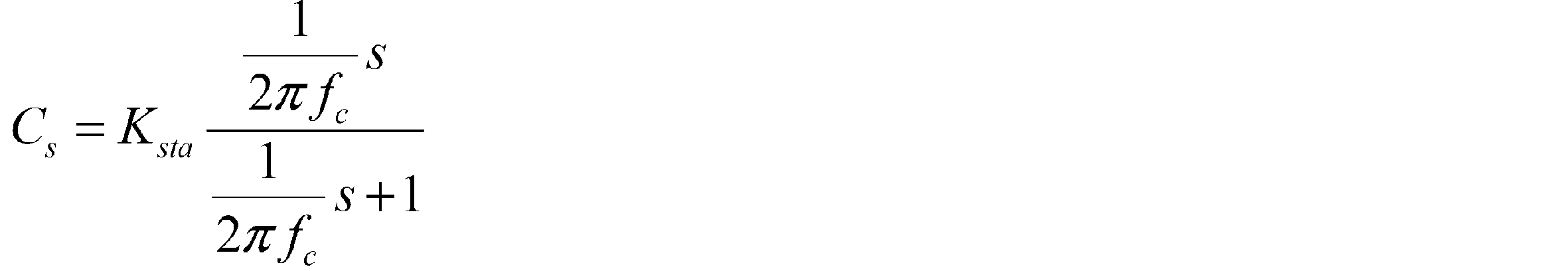
- the transfer function (Cs) of the stabilization compensator 145 for example, a first order filter expressed by the following equation 5 set by pseudo differentiation and gain using a first order HPF (high pass filter) structure is used.
- K sta is a gain
- fc is a center frequency, and, for example, 150 [Hz] is set as fc.
- the target twist angle ⁇ ref and the twist angle ⁇ are input (step S41), and the deviation ⁇ 0 is calculated by the subtracting unit 141 (step S42).
- Deviation ⁇ 0 is input to and compensated for torsion angle FB compensation unit 142 (step S43), and compensated target torsional angular velocity ⁇ ref is input to speed control unit 130.
- the torsion angle ⁇ is also input to the differentiating unit 143.
- the differentiating unit 143 differentiates the torsion angle ⁇ and outputs the torsion angular velocity ⁇ (step S44), and the torsion angular velocity ⁇ is also input to the speed control unit 130.
- the speed control unit 130 a difference of angular twist between the target torsion angular velocity omega ref omega is obtained by the subtraction unit 131, the difference is input to the integration (Kvi / s) has been added 134 the integration unit 132 (step S45) .
- the torsional angular velocity ⁇ is proportionally processed (Kvp) by the proportional unit 133, the proportional result is input to the adder 134 (step S45), and the current command value Is that is the addition result of the adder 134 is output and input to the adder 146. Is done.
- the motor angular velocity ⁇ m is input to the stabilization compensator 145, and the stabilization compensator 145 performs the stabilization compensation (step S46).
- the current command value Isb from the stabilization compensator 145 is input to the adder 146. .
- the adder 146 adds the current command values Is and Isb (step S47), and the current command value Isa as the addition result is input to the limiter 144 to limit the upper and lower limit values (step S48).
- the control current command value I ref is output (step S49).
- the effect of the stabilization compensator 145 will be described using a simulation result using the twist angle controller 140.
- FIG. 15B show the time change of the target twist angle (target steering torque) ⁇ ref (thin line) and the twist angle (steering torque) ⁇ (thick line), respectively.
- the stabilization compensator 145 When the stabilization compensator 145 is not used, if the gains of the torsion angle FB compensator 142 and the speed controller 130 are increased, the torsion angle ⁇ becomes oscillating as shown in FIG. It becomes impossible to follow the twist angle ⁇ ref .
- the stabilization compensator 145 is used, as shown in FIG. 15B, the thin line and the thick line substantially coincide with each other, the generation of vibration is suppressed, and the torsion angle FB compensator 142 and the speed controller 130. As a result, the target value followability can be improved.
- the target steering torque proportional to the rudder angular speed can be compensated to provide a feeling of viscosity as a feeling, and when the steering is turned off and released. Since the handle can oscillate, it can be given convergence, and the system stability can be improved.
- a simulation was conducted to confirm this. The simulation of letting go was performed by changing stepwise from 0 (Nm) to 0 [Nm] from the state where 3 [Nm] was applied from the start to 1 [sec] after manual input torque. .
- FIG. 14A and 16B FIG. 16A shows the time change of the steering angle ⁇ h
- FIG. 16A shows the time change of the steering angle ⁇ h
- FIG. 16B shows the time change of the target twist angle ⁇ ref (thin line) and the twist angle ⁇ (thick line). Yes.
- FIG. 16 shows that the steering angle ⁇ h is stably converged to 0 [deg].
- FIG. 17 shows a simulation result when the damper gain map 123 is not used. In this case, as shown in FIG. 17, the oscillation may be controlled.
- the motor angular velocity ⁇ m is used as the angle-related information
- the stabilization compensator 145 for the motor angular velocity ⁇ m is provided to stabilize the entire EPS control system.
- the twist angle [Delta] [theta] it provided the stability compensation unit for each motor angular speed omega m and the column angle .theta.c.
- FIG. 18 is a block diagram showing a basic configuration example of the second embodiment.
- the EPS steering system / vehicle system 200 has a torsion angle ⁇ and a motor angular velocity.
- ⁇ in addition to which the column angle ⁇ c is output of m the column angle ⁇ c is input to the torsion angle control unit 240.
- Other configurations are the same as those of the first embodiment. Therefore, compared with the operation example of the first embodiment shown in FIG. 6, the operation in the present configuration example is that the column angle ⁇ c is twisted in addition to the target twist angle ⁇ ref , the twist angle ⁇ , and the motor angular velocity ⁇ m in step S31. It is input to the angle control unit 240, and the operation of the torsion angle control unit in step S40 is different.
- twist angle control unit 240 A configuration example of the twist angle control unit 240 is shown in FIG. Compared to the configuration example of the torsion angle control unit 140 in the first embodiment shown in FIG. 12, stabilization compensation units 241 and 242 and addition units 243 and 244 are added. Since other configurations are the same as those of the first embodiment, description thereof is omitted.
- the torsion angle ⁇ is input to the stabilization compensator 241 of the compensation value Cs1 (transfer function), and the current command value Isb1 from the stabilization compensator 241 is input to the adder 244.
- the column angle ⁇ c is input to the stabilization compensator 242 of the compensation value Cs2 (transfer function), and the current command value Isb2 from the stabilization compensator 242 is input to the adder 243. Then, the current command value Isb0 (corresponding to the current command value Isb in the first embodiment) from the stabilization compensator 145 and the current command value Isb2 are added by the adder 243, and the current command value Isb1 is added to the addition result.
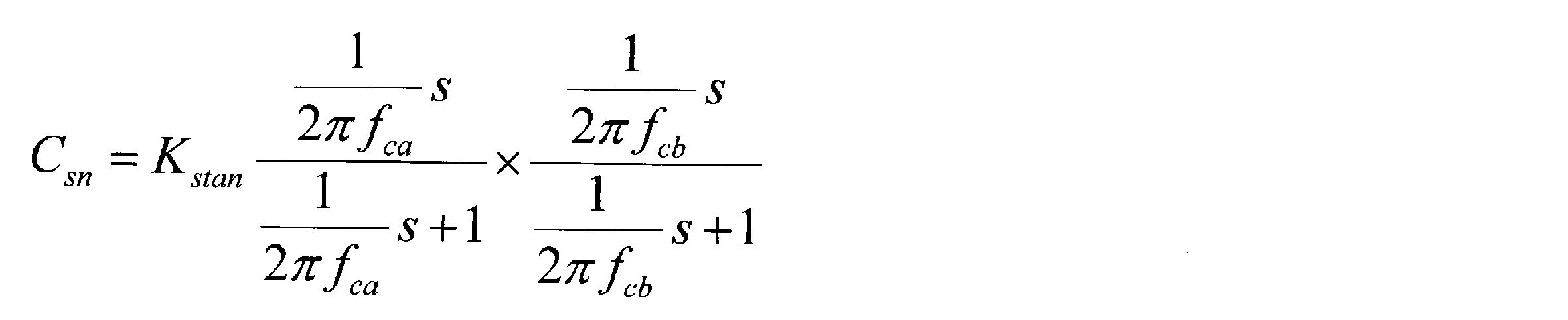
- K stan is a gain
- fca and fcb are center frequencies.
- the stabilization compensator 241 performs stabilization compensation on the input twist angle ⁇ (step S46A), and the current command value Isb1 from the stabilization compensator 241 is input to the adder 244.
- the motor angular velocity ⁇ m is input to the stabilization compensator 145 as in the case of the first embodiment, the stabilization compensator 145 performs the stabilization compensation (step S46B), and a current command from the stabilization compensator 145 is obtained.
- the value Isb0 is input to the adding unit 243.
- the column angle ⁇ c is input to the stabilization compensator 242.
- Stabilization compensation is performed by the stabilization compensator 242 (step S46C), and the current command value Isb2 from the stabilization compensator 242 is input to the adder 243.
- the current command values Isb0, Isb1, and Isb2 are added by the adders 243 and 244, and the current command value Isb is calculated (step S46D). That is, the current command values IIsb2 and Isb0 are added by the adder 243, the current command value Isb1 is added to the addition result by the adder 244, and the addition result is output as the current command value Isb.
- the current command value Isb is input to the adder 146. Thereafter, the same operation as in the first embodiment is performed (step S47 and subsequent steps).
- the stabilization compensator is provided for the torsion angle ⁇ , the motor angular velocity ⁇ m, and the column angle ⁇ c to perform the stabilization compensation.
- these stabilization compensations are selected and combined as appropriate. You may do it.
- the hysteresis correction unit 124 may be sensitive to the vehicle speed Vs in the same way as the basic map 121 and the damper gain map 123.
- a phase compensation unit may be inserted into the. For example, when it is desired to have a refreshing feeling with respect to steering, phase advance compensation may be set.
- the torque signal T ref_a may be the target steering torque T ref or the addition result of the torque signals T ref_a and T ref_c . May be the target steering torque T ref .
Landscapes
- Engineering & Computer Science (AREA)
- Chemical & Material Sciences (AREA)
- Combustion & Propulsion (AREA)
- Transportation (AREA)
- Mechanical Engineering (AREA)
- Steering Control In Accordance With Driving Conditions (AREA)
- Power Steering Mechanism (AREA)
- Control Of Electric Motors In General (AREA)
Abstract
【課題】路面の状態に影響されず、経年によるステアリング操舵系の機構特性の変化に左右されず、操舵角等の車両情報に対して同等の操舵トルクを容易に実現することが可能な電動パワーステアリング装置を提供する。 【解決手段】操舵系をアシスト制御する電動パワーステアリング装置において、車両運転情報に基づいて目標操舵トルクを生成する目標操舵トルク生成部と、目標操舵トルクを目標捩れ角に変換する変換部と、目標捩れ角、トーションバーの捩れ角及びモータ角速度に基づいて電流指令値を算出する捩れ角制御部とを備え、捩れ角制御部が、目標捩れ角及び捩れ角の偏差に対して目標捩れ角速度を出力する捩れ角フィードバック補償部と、目標捩れ角速度に基づいて電流指令値を出力する速度制御部と、少なくとも1つの角度関連情報に対して伝達関数を設定して電流指令値にフィードバックをかける安定化補償部とで構成される。
Description
本発明は、コラム軸(ステアリングシャフト、ハンドル軸)に備えられているトーションバーの捩れ角を、操舵角、車速、操舵状態等の車両運転情報に応じた値に追従するように制御することにより所望の操舵トルクを実現し、路面の状態に影響されず、経年による機構系特性の変化に左右されない高性能な電動パワーステアリング装置に関する。
モータ制御装置を搭載した装置として電動パワーステアリング装置(EPS)があり、電動パワーステアリング装置は、車両の操舵系にモータの回転力でアシスト力(操舵補助力)を付与するものであり、インバータから供給される電力で制御されるモータの駆動力を、減速機構を含む伝達機構により、ステアリングシャフト或いはラック軸にアシスト力として付与する。かかる従来の電動パワーステアリング装置は、アシスト力を正確に発生させるため、モータ電流のフィードバック制御を行っている。フィードバック制御は、操舵補助指令値(電流指令値)とモータ電流検出値との差が小さくなるようにモータ印加電圧を調整するものであり、モータ印加電圧の調整は、一般的にPWM(パルス幅変調)制御のデューティの調整で行っている。
電動パワーステアリング装置の一般的な構成を図1に示して説明すると、ハンドル1のコラム軸(ステアリングシャフト、ハンドル軸)2は減速機構3、ユニバーサルジョイント4a及び4b、ピニオンラック機構5、タイロッド6a,6bを経て、更にハブユニット7a,7bを介して操向車輪8L,8Rに連結されている。また、トーションバーを有するコラム軸2には、ハンドル1の操舵トルクTsを検出するトルクセンサ10及び操舵角θhを検出する舵角センサ14が設けられており、ハンドル1の操舵力を補助するモータ20が減速機構3を介してコラム軸2に連結されている。電動パワーステアリング装置を制御するコントロールユニット(ECU)30には、バッテリ13から電力が供給されると共に、イグニションキー11を経てイグニションキー信号が入力される。コントロールユニット30は、トルクセンサ10で検出された操舵トルクTsと車速センサ12で検出された車速Vsとに基づいてアシスト(操舵補助)指令の電流指令値の演算を行い、電流指令値に補償等を施した電圧制御指令値Vrefによって、EPS用モータ20に供給する電流を制御する。
コントロールユニット30には、車両の各種情報を授受するCAN(Controller Area Network)40が接続されており、車速VsはCAN40から受信することも可能である。また、コントロールユニット30には、CAN40以外の通信、アナログ/ディジタル信号、電波等を授受する非CAN41も接続可能である。
コントロールユニット30は主としてCPU(MCU、MPU等も含む)で構成されるが、そのCPU内部においてプログラムで実行される一般的な機能を示すと図2のようになる。
図2を参照してコントロールユニット30の機能及び動作を説明すると、トルクセンサ10で検出された操舵トルクTs及び車速センサ12で検出された(若しくはCAN40からの)車速Vsは、電流指令値Iref1を演算する電流指令値演算部31に入力される。電流指令値演算部31は、入力された操舵トルクTs及び車速Vsに基づいてアシストマップ等を用いて、モータ20に供給する電流の制御目標値である電流指令値Iref1を演算する。電流指令値Iref1は加算部32Aを経て電流制限部33に入力され、最大電流を制限された電流指令値Irefmが減算部32Bに入力され、フィードバックされているモータ電流値Imとの偏差I(=Irefm-Im)が演算され、その偏差Iが操舵動作の特性改善のためのPI(比例積分)制御部35に入力される。PI制御部35で特性改善された電圧制御指令値VrefがPWM制御部36に入力され、更に駆動部としてのインバータ37を介してモータ20がPWM駆動される。モータ20の電流値Imはモータ電流検出器38で検出され、減算部32Bにフィードバックされる。
加算部32Aには補償信号生成部34からの補償信号CMが加算されており、補償信号CMの加算によって操舵システム系の特性補償を行い、収れん性や慣性特性等を改善するようになっている。補償信号生成部34は、セルフアライニングトルク(SAT)34-3と慣性34-2を加算部34-4で加算し、その加算結果に更に収れん性34-1を加算部34-5で加算し、加算部34-5の加算結果を補償信号CMとしている。
このように従来のアシスト制御では、運転者の手入力にて加えた操舵トルク(トーションバーの捩れトルク)をトルクセンサで検出し、主にそのトルクに応じたアシスト電流としてモータ電流を制御している。しかしながら、この手法では、路面の状態(例えば傾斜)の違いにより、操舵角によって異なる操舵トルクとなってしまうことがある。また、モータ出力特性の経年使用によるバラツキにもより、異なる操舵特性になってしまう。
かかる問題を解決する車両制御装置として、例えば特許第5208894号公報(特許文献1)に示されるものがある。特許文献1の装置は、運転者の触覚特性に基づく適切な操舵トルクを与えることができるように、操舵角検出手段と、目標設定手段と、目標設定手段によって設定された操舵トルクの目標値が実現されるように制御する制御手段とを具備している。
しかしながら、特許文献1の装置では、操舵角と操舵トルクとの対応関係を、操舵角又は操舵トルクと手応え量との関係に基づいて予め求めておく必要があり、その対応関係から操舵角に対応する操舵トルクを目標値として設定しなければならない煩雑さがある。また、特許文献1の装置は、操舵トルクの目標値と検出される操舵トルクとの偏差に対してPI制御を用いている。
本発明は上述のような事情よりなされたものであり、本発明の目的は、路面の状態に影響されず、経年によるステアリング操舵系の機構特性の変化に左右されず、操舵角等の車両運転情報に対して同等の操舵トルクを容易に実現することが可能な電動パワーステアリング装置を提供することにある。
本発明は、車両のハンドルのコラム軸にトーションバーを備え、前記コラム軸に接続されたモータを電流指令値に基づいて駆動制御することにより、操舵系をアシスト制御する電動パワーステアリング装置に関し、本発明の上記目的は、車両運転情報に基づいて目標操舵トルクを生成する目標操舵トルク生成部と、前記目標操舵トルクを目標捩れ角に変換する変換部と、前記目標捩れ角、前記トーションバーの捩れ角及びモータ角速度に基づいて前記電流指令値を算出する捩れ角制御部と、を備え、前記捩れ角制御部が、前記目標捩れ角及び前記捩れ角の偏差に対して目標捩れ角速度を出力する捩れ角フィードバック補償部と、前記目標捩れ角速度に基づいて前記電流指令値を出力する速度制御部と、少なくとも1つの角度関連情報に対して伝達関数を設定して前記電流指令値にフィードバックをかける安定化補償部と、で構成され、前記捩れ角を前記車両運転情報に応じた値に追従するように制御することにより達成される。
また、本発明の上記目的は、前記角度関連情報が前記モータ角速度であり、前記安定化補償部が、前記モータ角速度に対して伝達関数を設定して前記電流指令値にフィードバックをかけることにより、或いは前記伝達関数が1次のHPFとゲインにより設定されることにより、或いは前記角度関連情報が前記捩れ角、前記モータ角速度及びコラム角であり、前記安定化補償部が、前記捩れ角、前記モータ角速度及びコラム角それぞれに対して伝達関数を設定して前記電流指令値にフィードバックをかけることにより、或いは前記モータ角速度に対する前記伝達関数が1次のHPFとゲインにより設定され、前記捩れ角に対する前記伝達関数が2次以上のフィルタにより設定され、前記コラム角に対する前記伝達関数が2次以上のフィルタにより設定されることにより、或いは前記目標操舵トルク生成部が、前記車両運転情報に応じて車速感応のトルク信号1を出力する基本マップと、前記基本マップの前段又は後段に位相補償部と、前記トルク信号1又は前記位相補償部を介したトルク信号1を前記目標操舵トルクとして出力する出力部と、を備えていることにより、或いは前記目標操舵トルク生成部に前記ハンドルの右切り/左切りの操舵状態が入力され、前記目標操舵トルク生成部が、前記操舵状態に応じて前記車両運転情報をヒステリシス補正してトルク信号2を出力するヒステリシス補正部を更に備え、前記出力部が前記トルク信号1及び前記トルク信号2を加算して前記目標操舵トルクを出力することにより、或いは前記目標操舵トルク生成部が、前記車両運転情報の微分値に車速感応ダンパゲインを乗算してトルク信号3を出力するダンパゲイン部を更に備え、前記出力部が前記トルク信号1、前記トルク信号2及び前記トルク信号3を加算して前記目標操舵トルクを出力することにより、或いは前記速度制御部の後段に上下限値を制限するリミッタが設けられていることにより、或いは前記捩れ角フィードバック補償部が伝達関数のゲイン値であることにより、或いは前記車両運転情報が操舵角、車速、操舵状態であることにより、より効果的に達成される。
本発明の電動パワーステアリング装置によれば、車速及び操舵角等の車両運転情報から目標捩れ角を生成し、目標捩れ角と検出された捩れ角との偏差に補償値(伝達関数)を乗算した結果を目標捩れ角速度として、速度制御することで、目標捩れ角に捩れ角が追従するように動作し、操舵角等の車両運転情報に対して所望の操舵トルクを実現し、運転者の操舵の感覚に基づく適切な操舵トルクを与えることができる。捩れ角制御部が捩れ角速度を制御する速度制御部を備えており、これにより目標捩れ角への追従性が向上し、更に、運転者から入力される操舵角の変化による捩れ角への影響を抑制し、急な操舵に対する目標捩れ角への捩れ角の追従性を向上することができる。
また、角度関連情報に対し、安定化するために必要な伝達関数(2次フィルタ若しくは4次フィルタ等)による安定化補償部を設けているので、EPS制御システム全体の安定化を実現することができる。
目標捩れ角へ捩れ角を追従させるために単純にゲインを上げると発振や振動が発生するが、安定化補償部による信号のフィードバックにより発振や振動を抑制できる。また、安定化補償部を設けることにより、高周波数帯域に発生する振動の発生を抑え、結果的に捩れ角フィードバック補償部のゲインを大きくし、指令値に対する追従性を向上することができる。
本発明は、路面の状態に影響されず、操舵角、車速、操舵状態等の車両運転情報に対して同等の操舵トルクを実現するための電動パワーステアリング装置であり、コラム軸に備えられているトーションバーの捩れ角を、車両運転情報に応じた値に追従するように制御することにより所望の操舵トルクを実現している。また、システムの安定性を向上させる安定化補償部を設けることで、発振現象の対策を行うようにしており、これにより、目標値追従性を高める方向にゲインを調整することができ、結果的に追従性を向上することができる。
以下に、本発明の実施の形態を、図面を参照して説明する。
図3は本発明の基本構成例(第1実施形態)を示すブロック図であり、運転者のハンドル操舵はEPS操舵系/車両系100内のモータでアシスト制御される。操舵角θh等の車両運転情報に応じた目標操舵トルクTrefを出力する目標操舵トルク生成部120には、車両運転情報である操舵の右切り又は左切りの操舵状態STs、車速Vs及び操舵角θhが入力され、目標操舵トルク生成部120で生成された目標操舵トルクTrefは、コラム軸2に設けられているトーションバー2Aのバネ定数をKtorとして、“1/Ktor”の特性を有する変換部101で目標捩れ角Δθrefに変換され、目標捩れ角Δθrefは捩れ角制御部140に入力される。捩れ角制御部140には目標捩れ角Δθref、捩れ角Δθ及びモータ角速度ωmが入力されており、捩れ角制御部140で捩れ角Δθが目標捩れ角Δθrefとなるような電流指令値Irefが演算され、電流指令値IrefによりEPSのモータが駆動される。
EPS操舵系と各種センサの設置例は図4に示すようになっており、コラム軸2にはトーションバー2Aが備えられている。操向車輪8L,8Rには路面反力Fr及び路面情報μが作用し、トーションバー2Aを挟んでコラム軸2のハンドル側には上側角度センサ(角度θ1)が設けられ、トーションバー2Aを挟んでコラム軸2の操向車輪側には下側角度センサ(角度θ2)が設けられている。操舵角θhはコラム軸2の上部に設けられた舵角センサで検出され、上側角度センサの角度θ1及び下側角度センサの角度θ2の偏差から、下記数1及び数2によってトーションバー捩れ角Δθ及びトーションバートルクTtを求めることができる。なお、Ktorはトーションバー2Aのバネ定数である。
このような構成において、本実施形態の動作例を図6のフローチャートを参照して説明する。
先ず、操舵角θh、操舵状態STs、車速Vsが目標操舵トルク生成部120に入力され(ステップS1)、目標操舵トルク生成部120は目標操舵トルクTrefを生成する(ステップS10)。目標操舵トルクTrefは変換部101に入力され、変換部101で目標捩れ角Δθrefに変換される(ステップS30)。目標捩れ角Δθref、捩れ角Δθ及びモータ角速度ωmが捩れ角制御部140に入力され(ステップS31)、捩れ角制御部140は捩れ角Δθが目標捩れ角Δθrefに追従するような電流指令値Irefを演算し(ステップS40)、電流指令値Irefに基づいてモータを駆動し、電流制御が実施される(ステップS60)。
なお、図6におけるデータの入力順番は適宜変更可能である。
図7は目標操舵トルク生成部120の構成例を示しており、操舵角θhは基本マップ121、微分部122及びヒステリシス補正部124に入力され、基本マップ121は、図8に示すような車速Vsをパラメータとするトルク信号Tref_aを出力する。図8では操舵角θhの絶対値|θh|でマップを構成しているが、正負の操舵角θhに応じてトルク信号Tref_aを出力するようにしても良い。トルク信号Tref_aは加算部126に入力される。
また、微分部122からは、操舵角θhを微分して得られる舵角速度ωhが出力され、舵角速度ωhは乗算部125に入力される。乗算部125には車速感応ダンパゲインDGが入力されており、乗算結果(=DG・ωh)であるトルク信号Tref_bは加算部127に入力される。車速感応ダンパゲインDGは車速感応のダンパゲインマップ123から車速Vsに応じて出力され、例えば図9に示すように車速Vsが高くなるに従って徐々に大きくなる特性である。なお、ダンパゲインマップ123及び乗算部125でダンパゲイン部を構成している。
右切り/左切り判定部110は例えば図5に示すような判定を行い、判定結果である操舵状態STsをヒステリシス補正部124に入力する。ヒステリシス補正部124には操舵角θhが入力されており、ヒステリシス補正部124は操舵角θh及び操舵状態STsに基づき、下記数3に従ってトルク信号Tref_cを演算する。ただし、x=θh、y=Tref_cとしている。


このような構成において、目標操舵トルク生成部120の動作例(図6のステップS10)を、図11のフローチャートを参照して説明する。
先ず、操舵角θh及び車速Vsが入力され(ステップS11)、基本マップ121は図8の特性に従い、操舵角θh及び車速Vsに応じたトルク信号Tref_aを生成して出力する(ステップS12)。操舵角θhは微分部122及びヒステリシス補正部124にも入力され、微分部122は操舵角θhを微分して舵角速度ωhを出力し(ステップS13)、ダンパゲインマップ123は車速Vsに応じた車速感応ダンパゲインDGを出力し(ステップS14)、乗算部125は舵角速度ωh及び車速感応ダンパゲインDGを乗算してトルク信号Tref_bを演算し、トルク信号Tref_bを加算部127に入力する(ステップS15)。
また、右切り/左切り判定部110は操舵の右切り/左切りを判定し、判定結果である操舵状態STsをヒステリシス補正部124に入力する(ステップS16)。ヒステリシス補正部124は操舵角θhに対して、且つ操舵状態STsに応じて数3及び数4の演算を行ってヒステリシス補正を実施し(ステップS17)、トルク信号Tref_cを生成する(ステップS18)。トルク信号Tref_cは加算部127に入力される。
上述のようにして得られたトルク信号Tref_a、トルク信号Tref_b及びトルク信号Tref_cは出力部を構成する加算部126及び127で加算され、目標操舵トルクTrefが演算される(ステップS19)。即ち、トルク信号Tref_bとトルク信号Tref_cが加算部127で加算され、その加算結果にトルク信号Tref_aが加算部126で加算され、その加算結果が目標操舵トルクTrefとして出力される。
なお、図11のデータ入力及び演算等の順番は適宜変更可能である。
図12は捩れ角制御部140の構成例を示すブロック図であり、目標捩れ角Δθrefと捩れ角Δθの偏差Δθ0が減算部141で算出され、偏差Δθ0は補償値CFB(伝達関数)の捩れ角フィードバック(FB)補償部142に入力される。捩れ角FB補償部142は偏差Δθ0に対し補償値CFB(伝達関数)を乗算し、目標捩れ角Δθrefに捩れ角Δθが追従するような目標捩れ角速度ωrefを出力する。目標捩れ角速度ωrefは、I-P制御(比例先行型PI制御)の速度制御部130に入力される。なお、補償値CFBは単純なゲインKppでも、或いはPI制御の補償値などでも良い。
捩れ角Δθは微分部143にも入力され、微分部143は、捩れ角Δθを微分して得られる捩れ角速度ωを出力する。捩れ角速度ωは速度制御部130に入力される。
I-P制御の速度制御部130は、目標捩れ角速度ωrefに捩れ角速度ωが追従するような電流指令値Isを算出する。電流指令値Isは加算部146に入力される。
モータ角速度ωmは角度関連情報として補償値Cs(伝達関数)の安定化補償部145に入力され、安定化補償部145からの電流指令値Isbが加算部146に入力される。追従性及び外乱特性を向上させるために、捩れ角FB補償部142及び速度制御部130のゲインを上げると、高域の制御的な発振現象が発生してしまう。この対策として、モータ角速度ωmに対し、安定化するために必要な伝達関数(Cs)を安定化補償部145に設定する。これにより、EPS制御システム全体の安定化を実現することができる。安定化補償部145の伝達関数(Cs)として、例えば1次のHPF(ハイパスフィルタ)の構造を用いた擬似微分とゲインにより設定した、下記数5で表わされる1次フィルタを使用する。
速度制御部130からの電流指令値Is及び安定化補償部145からの電流指令値Isbは加算部146で加算され、加算で得られた電流指令値Isaの上下限値を制限して、電流指令値Irefを出力するリミッタ144が設けられている。
このような構成において、捩れ角制御部140の動作例(図6のステップS40)を、図13のフローチャートを参照して説明する。
先ず目標捩れ角Δθref及び捩れ角Δθが入力され(ステップS41)、減算部141で偏差Δθ0が算出される(ステップS42)。偏差Δθ0は捩れ角FB補償部142に入力されて補償され(ステップS43)、補償された目標捩れ角速度ωrefは速度制御部130に入力される。捩れ角Δθは微分部143にも入力され、微分部143は捩れ角Δθを微分して捩れ角速度ωを出力し(ステップS44)、捩れ角速度ωも速度制御部130に入力される。
速度制御部130では、目標捩れ角速度ωrefと捩れ角速度ωの差分が減算部131で得られ、差分が積分部132で積分(Kvi/s)されて加算部134に入力される(ステップS45)。捩れ角速度ωは比例部133で比例処理(Kvp)され、比例結果が加算部134に入力され(ステップS45)、加算部134の加算結果である電流指令値Isが出力され、加算部146に入力される。
モータ角速度ωmは安定化補償部145に入力され、安定化補償部145で安定化補償が実施され(ステップS46)、安定化補償部145からの電流指令値Isbは加算部146に入力される。加算部146で電流指令値Is及びIsbの加算が行われ(ステップS47)、加算結果である電流指令値Isaはリミッタ144に入力されて上下限値を制限され(ステップS48)、リミッタ144からモータ制御の電流指令値Irefが出力される(ステップS49)。
本実施形態の効果について説明する。
先ず、捩れ角制御部140を用いたシミュレーション結果を用いて、安定化補償部145の効果について説明する。
安定化補償部145の効果をわかりやすく示すために、トルクセンサ(捩れ角センサ)の信号は遅い信号であることを想定し、1次LPF(ローパスフィルタ)(カットオフ周波数50Hz)を意図的に適用した信号を捩れ角制御部140にフィードバックしてシミュレーションを行った。その結果を図14及び図15に示す。図14は安定化補償部145を用いない場合の結果を、図15は安定化補償部145を用いた場合の結果を示しており、図14(A)及び図15(A)は操舵角θhの時間変化を、図14(B)及び図15(B)は目標捩れ角(目標操舵トルク)Δθref(細線)と捩れ角(操舵トルク)Δθ(太線)の時間変化をそれぞれ示している。安定化補償部145を用いない場合、捩れ角FB補償部142及び速度制御部130のゲインを上げると、図14(B)に示されるように、捩れ角Δθは振動的になってしまい、目標捩れ角Δθrefに対して追従しきれなくなる。一方、安定化補償部145を用いた場合は、図15(B)に示されるように、細線と太線が概ね一致し、振動の発生が抑制され、捩れ角FB補償部142及び速度制御部130のゲインを十分に上げることができるので、結果的に目標値追従性を向上させることができる。
次に、ダンパゲインマップ123の効果を、シミュレーション結果を用いて説明する。
車速感応のダンパゲインマップ123の効果として、舵角速度に比例した目標操舵トルクを補償することにより、フィーリングとしての粘性感を持たせることができること、ステアリングを切った状態から手放しの状態にした場合、ハンドルが発振することなく、収れん性を持たせられ、システム安定性を向上させることができることが挙げられるので、それを確認するためのシミュレーションを行った。手放しのシミュレーションは、手入力トルクを開始から1[sec]まで3[Nm]加えた状態(操舵角θhは30[deg]弱)から、0[Nm]にステップ的に変化させることにより行った。その結果を図16に示す。図14及び図15と同様に、図16(A)は操舵角θhの時間変化を、図16(B)は目標捩れ角Δθref(細線)と捩れ角Δθ(太線)の時間変化を示している。図16から、操舵角θhが0[deg]に安定して収束していることがわかる。ダンパゲインマップ123を用いない場合のシミュレーション結果を図17に示すが、この場合には、図17に示されるように、制御的に発振してしまうことがある。
本発明の他の実施形態(第2実施形態)について説明する。
第1実施形態では、角度関連情報としてモータ角速度ωmを使用し、モータ角速度ωmに対する安定化補償部145を設けて、EPS制御システム全体の安定化を図っているが、第2実施形態では、角度関連情報としてモータ角速度ωmの他に捩れ角Δθ及びコラム角θcを使用し、捩れ角Δθ、モータ角速度ωm及びコラム角θcそれぞれに対して安定化補償部を設ける。
図18は第2実施形態の基本構成例を示すブロック図であり、図3に示される第1実施形態の基本構成例と比べると、EPS操舵系/車両系200からは捩れ角Δθ及びモータ角速度ωmの他にコラム角θcが出力されており、コラム角θcは捩れ角制御部240に入力される。その他の構成は、第1実施形態と同じである。よって、本構成例における動作は、図6に示される第1実施形態の動作例と比べると、ステップS31において目標捩れ角Δθref、捩れ角Δθ及びモータ角速度ωmに加えてコラム角θcが捩れ角制御部240に入力されることになり、ステップS40における捩れ角制御部での動作が異なることになる。
捩れ角制御部240の構成例を図19に示す。図12に示される第1実施形態での捩れ角制御部140の構成例と比べると、安定化補償部241及び242並びに加算部243及び244が追加されている。その他の構成は第1実施形態と同じであるから、説明は省略する。
補償値Cs1(伝達関数)の安定化補償部241には捩れ角Δθが入力され、安定化補償部241からの電流指令値Isb1が加算部244に入力される。補償値Cs2(伝達関数)の安定化補償部242にはコラム角θcが入力され、安定化補償部242からの電流指令値Isb2が加算部243に入力される。そして、安定化補償部145からの電流指令値Isb0(第1実施形態での電流指令値Isbに相当)と電流指令値Isb2が加算部243で加算され、更に、その加算結果に電流指令値Isb1が加算部244で加算され、電流指令値Isbとして加算部146に出力される。安定化補償部241及び242の伝達関数(Cs1、Cs2)としては、例えば下記数6で表わされる2次フィルタをそれぞれ独立して使用する。
このような構成において、捩れ角制御部240の動作例を、図20のフローチャートを参照して説明する。
ステップS45までは第1実施形態と同様の動作が実施される。
安定化補償部241では、入力した捩れ角Δθに対して安定化補償を実施し(ステップS46A)、安定化補償部241からの電流指令値Isb1は加算部244に入力される。モータ角速度ωmは、第1実施形態の場合と同様に安定化補償部145に入力され、安定化補償部145で安定化補償が実施され(ステップS46B)、安定化補償部145からの電流指令値Isb0は加算部243に入力される。コラム角θcは安定化補償部242に入力され、安定化補償部242で安定化補償が実施され(ステップS46C)、安定化補償部242からの電流指令値Isb2は加算部243に入力される。
電流指令値Isb0、Isb1及びIsb2は加算部243及び244で加算され、電流指令値Isbが演算される(ステップS46D)。即ち、電流指令値IIsb2とIsb0が加算部243で加算され、その加算結果に電流指令値Isb1が加算部244で加算され、その加算結果が電流指令値Isbとして出力される。電流指令値Isbは加算部146に入力される。それ以降は第1実施形態と同様の動作が実施される(ステップS47~)。
なお、本実施形態では捩れ角Δθ、モータ角速度ωm及びコラム角θcに対して安定化補償部を設置して安定化補償を行っているが、これらの安定化補償を取捨選択し、適宜組み合わせるようにしても良い。
上述の実施形態(第1及び第2実施形態)において、ヒステリシス補正部124を、基本マップ121及びダンパゲインマップ123と同様に車速Vsに感応したものにしても良く、基本マップ121の後段若しくは前段に位相補償部を挿入しても良い。例えば操舵に対してスッキリ感を持たせたい場合は、位相進み補償を設定すれば良い。また、トルク信号Tref_a、Tref_b及びTref_cの加算結果を目標操舵トルクTrefとしているが、トルク信号Tref_aを目標操舵トルクTrefとしても良いし、トルク信号Tref_a及びTref_cの加算結果を目標操舵トルクTrefとしても良い。
また、捩れ角制御部の電流指令値Irefに従来のアシスト制御の電流指令値、或いはSAT(Self-Aligning Torque)推定値の電流指令値、或いはハンドル振動抑制のための電流指令値を加算しても良い。
更に、上述の実施形態では速度制御部をI-P制御(比例先行型PI制御)で構成しているが、PI制御、P制御、PID制御、PI-D制御、モデルマッチング制御、モデル規範制御などの一般的に用いられるものでも良い。
上述の実施形態では、舵角速度は、操舵角θhに対する微分演算により求めているが、高域のノイズの影響を低減するために適度にLPF処理を実施している。また、HPF(ハイパスフィルタ)とゲインにより、微分演算とLPFの処理を実施しても良い。更に、舵角速度は、操舵角θhではなく、上側角度センサの検出角度θ1、若しくは下側角度センサの検出角度θ2、若しくはモータに連結された回転角センサの検出角度に対して微分演算とLPFの処理を行った信号でも良い。
1 ハンドル
2 コラム軸(ステアリングシャフト、ハンドル軸)
3 減速機構
10 トルクセンサ
12 車速センサ
14 舵角センサ
20 モータ
30 コントロールユニット(ECU)
100、200 EPS操舵系/車両系
101 変換部
110 右切り/左切り判定部
120 目標操舵トルク生成部
121 基本マップ
123 ダンパゲインマップ
124 ヒステリシス補正部
130 速度制御部
140、240 捩れ角制御部
142 捩れ角フィードバック(FB)補償部
145、241、242 安定化補償部
2 コラム軸(ステアリングシャフト、ハンドル軸)
3 減速機構
10 トルクセンサ
12 車速センサ
14 舵角センサ
20 モータ
30 コントロールユニット(ECU)
100、200 EPS操舵系/車両系
101 変換部
110 右切り/左切り判定部
120 目標操舵トルク生成部
121 基本マップ
123 ダンパゲインマップ
124 ヒステリシス補正部
130 速度制御部
140、240 捩れ角制御部
142 捩れ角フィードバック(FB)補償部
145、241、242 安定化補償部
Claims (11)
- 車両のハンドルのコラム軸にトーションバーを備え、前記コラム軸に接続されたモータを電流指令値に基づいて駆動制御することにより、操舵系をアシスト制御する電動パワーステアリング装置において、
車両運転情報に基づいて目標操舵トルクを生成する目標操舵トルク生成部と、
前記目標操舵トルクを目標捩れ角に変換する変換部と、
前記目標捩れ角、前記トーションバーの捩れ角及びモータ角速度に基づいて前記電流指令値を算出する捩れ角制御部と、
を備え、
前記捩れ角制御部が、
前記目標捩れ角及び前記捩れ角の偏差に対して目標捩れ角速度を出力する捩れ角フィードバック補償部と、
前記目標捩れ角速度に基づいて前記電流指令値を出力する速度制御部と、
少なくとも1つの角度関連情報に対して伝達関数を設定して前記電流指令値にフィードバックをかける安定化補償部と、
で構成され、前記捩れ角を前記車両運転情報に応じた値に追従するように制御することを特徴とする電動パワーステアリング装置。 - 前記角度関連情報が前記モータ角速度であり、
前記安定化補償部が、前記モータ角速度に対して伝達関数を設定して前記電流指令値にフィードバックをかける請求項1に記載の電動パワーステアリング装置。 - 前記伝達関数が1次のHPFとゲインにより設定される請求項2に記載の電動パワーステアリング装置。
- 前記角度関連情報が前記捩れ角、前記モータ角速度及びコラム角であり、
前記安定化補償部が、前記捩れ角、前記モータ角速度及びコラム角それぞれに対して伝達関数を設定して前記電流指令値にフィードバックをかける請求項1に記載の電動パワーステアリング装置。 - 前記モータ角速度に対する前記伝達関数が1次のHPFとゲインにより設定され、
前記捩れ角に対する前記伝達関数が2次以上のフィルタにより設定され、
前記コラム角に対する前記伝達関数が2次以上のフィルタにより設定される請求項4に記載の電動パワーステアリング装置。 - 前記目標操舵トルク生成部が、
前記車両運転情報に応じて車速感応のトルク信号1を出力する基本マップと、
前記基本マップの前段又は後段に位相補償部と、
前記トルク信号1又は前記位相補償部を介したトルク信号1を前記目標操舵トルクとして出力する出力部と、
を備えている請求項1乃至5のいずれかに記載の電動パワーステアリング装置。 - 前記目標操舵トルク生成部に前記ハンドルの右切り/左切りの操舵状態が入力され、
前記目標操舵トルク生成部が、
前記操舵状態に応じて前記車両運転情報をヒステリシス補正してトルク信号2を出力するヒステリシス補正部を更に備え、
前記出力部が前記トルク信号1及び前記トルク信号2を加算して前記目標操舵トルクを出力する請求項6に記載の電動パワーステアリング装置。 - 前記目標操舵トルク生成部が、
前記車両運転情報の微分値に車速感応ダンパゲインを乗算してトルク信号3を出力するダンパゲイン部を更に備え、
前記出力部が前記トルク信号1、前記トルク信号2及び前記トルク信号3を加算して前記目標操舵トルクを出力する請求項7に記載の電動パワーステアリング装置。 - 前記速度制御部の後段に上下限値を制限するリミッタが設けられている請求項1乃至8のいずれかに記載の電動パワーステアリング装置。
- 前記捩れ角フィードバック補償部が伝達関数のゲイン値である請求項1乃至9のいずれかに記載の電動パワーステアリング装置。
- 前記車両運転情報が操舵角、車速、操舵状態である請求項1乃至10のいずれかに記載の電動パワーステアリング装置。
Priority Applications (4)
| Application Number | Priority Date | Filing Date | Title |
|---|---|---|---|
| JP2018549045A JP6504322B2 (ja) | 2016-11-07 | 2017-11-01 | 電動パワーステアリング装置 |
| CN201780061865.0A CN109963772B (zh) | 2016-11-07 | 2017-11-01 | 电动助力转向装置 |
| EP17867552.6A EP3489114B1 (en) | 2016-11-07 | 2017-11-01 | Electric power steering apparatus |
| US16/327,606 US10589780B2 (en) | 2016-11-07 | 2017-11-01 | Electric power steering apparatus |
Applications Claiming Priority (4)
| Application Number | Priority Date | Filing Date | Title |
|---|---|---|---|
| JP2016-217411 | 2016-11-07 | ||
| JP2016217411 | 2016-11-07 | ||
| JP2016-217410 | 2016-11-07 | ||
| JP2016217410 | 2016-11-07 |
Publications (1)
| Publication Number | Publication Date |
|---|---|
| WO2018084190A1 true WO2018084190A1 (ja) | 2018-05-11 |
Family
ID=62077020
Family Applications (1)
| Application Number | Title | Priority Date | Filing Date |
|---|---|---|---|
| PCT/JP2017/039584 Ceased WO2018084190A1 (ja) | 2016-11-07 | 2017-11-01 | 電動パワーステアリング装置 |
Country Status (5)
| Country | Link |
|---|---|
| US (1) | US10589780B2 (ja) |
| EP (1) | EP3489114B1 (ja) |
| JP (1) | JP6504322B2 (ja) |
| CN (1) | CN109963772B (ja) |
| WO (1) | WO2018084190A1 (ja) |
Cited By (11)
| Publication number | Priority date | Publication date | Assignee | Title |
|---|---|---|---|---|
| WO2019193976A1 (ja) * | 2018-04-06 | 2019-10-10 | 日本精工株式会社 | 車両用操向装置 |
| JP2020055357A (ja) * | 2018-09-28 | 2020-04-09 | 日本電産株式会社 | トルク制御装置およびパワーステアリング装置 |
| WO2020145036A1 (ja) * | 2019-01-11 | 2020-07-16 | 日本精工株式会社 | 車両用操向装置 |
| WO2020157683A1 (en) * | 2019-01-29 | 2020-08-06 | Aptiv Technologies Limited | Electric power steering torque compensation |
| WO2020183838A1 (ja) * | 2019-03-08 | 2020-09-17 | 日本精工株式会社 | 車両用操向装置 |
| WO2020213287A1 (ja) * | 2019-04-18 | 2020-10-22 | 日本精工株式会社 | 車両用操向システムの制御装置 |
| WO2020213285A1 (ja) * | 2019-04-15 | 2020-10-22 | 日本精工株式会社 | 車両用操向装置 |
| JP2020185819A (ja) * | 2019-05-10 | 2020-11-19 | 日本精工株式会社 | 車両用操向装置 |
| KR20200133390A (ko) * | 2019-01-29 | 2020-11-27 | 모셔널 에이디 엘엘씨 | 전동 조향 토크 보상 |
| JP2021138327A (ja) * | 2020-03-09 | 2021-09-16 | 日本電産株式会社 | 電動パワーステアリング装置に用いられる制御装置、制御方法、およびモータモジュール |
| US20220289286A1 (en) * | 2021-03-15 | 2022-09-15 | Continental Automotive Gmbh | Regulating device and method for regulating the steering angle of a vehicle |
Families Citing this family (18)
| Publication number | Priority date | Publication date | Assignee | Title |
|---|---|---|---|---|
| EP3434559A4 (en) * | 2016-09-16 | 2019-11-20 | NSK Ltd. | POWER ASSISTED STEERING DEVICE |
| JP6575504B2 (ja) * | 2016-12-26 | 2019-09-18 | トヨタ自動車株式会社 | モータ制御システム |
| US10661825B2 (en) * | 2017-03-16 | 2020-05-26 | Nsk Ltd. | Electric power steering apparatus |
| KR102552925B1 (ko) * | 2018-07-20 | 2023-07-10 | 에이치엘만도 주식회사 | 스티어 바이 와이어 시스템의 제어 장치 및 방법 |
| KR102687171B1 (ko) * | 2019-08-09 | 2024-07-19 | 현대자동차주식회사 | 전동식 파워 조향 제어방법 및 제어시스템 |
| JP7359045B2 (ja) * | 2020-03-09 | 2023-10-11 | 株式会社ジェイテクト | モータの制御装置 |
| JP7338520B2 (ja) * | 2020-03-11 | 2023-09-05 | 株式会社ジェイテクト | 操舵制御装置 |
| KR102788837B1 (ko) * | 2020-04-16 | 2025-04-01 | 현대모비스 주식회사 | 자율주행 모드에서의 조향 제어 장치 및 방법 |
| CN111649964B (zh) * | 2020-06-11 | 2022-07-12 | 北京经纬恒润科技股份有限公司 | 车辆负载模拟系统及车辆转向负载模拟方法 |
| CN114104093B (zh) * | 2020-08-25 | 2025-11-07 | 株式会社捷太格特 | 转向控制装置 |
| DE102021201141A1 (de) * | 2021-02-08 | 2022-08-11 | Continental Automotive Gmbh | Regelungseinrichtung und Verfahren zur Lenkwinkelregelung eines Fahrzeugs |
| US11685427B2 (en) | 2021-04-12 | 2023-06-27 | Toyota Material Handling, Inc. | Electric actuator steering system for forklifts |
| JP7615896B2 (ja) * | 2021-06-04 | 2025-01-17 | 株式会社デンソー | ステアリング制御装置 |
| US12522277B2 (en) | 2021-07-20 | 2026-01-13 | Toyota Material Handling, Inc. | Forklift steer-by-wire control system |
| CN114889688B (zh) * | 2022-05-12 | 2023-10-20 | 一汽奔腾轿车有限公司 | 一种基于汽车eps的转向阻尼控制方法 |
| CA3209767A1 (en) | 2022-09-28 | 2024-03-28 | Toyota Material Handling, Inc. | Synchronized steering control systems for forklifts |
| JP7843927B2 (ja) | 2023-05-25 | 2026-04-10 | 三菱電機モビリティ株式会社 | 操舵制御装置、電動パワーステアリング装置、及び車両 |
| BE1031887B1 (de) * | 2023-08-11 | 2025-03-10 | Thyssenkrupp Presta Ag | Lenkeinrichtung für ein Kraftfahrzeug |
Citations (3)
| Publication number | Priority date | Publication date | Assignee | Title |
|---|---|---|---|---|
| JP2002104210A (ja) * | 2000-09-28 | 2002-04-10 | Toyoda Mach Works Ltd | 電動パワーステアリング装置の制御装置 |
| JP2014065492A (ja) * | 2013-11-21 | 2014-04-17 | Nsk Ltd | 電動パワーステアリング装置 |
| WO2016072143A1 (ja) * | 2014-11-07 | 2016-05-12 | 日本精工株式会社 | 電動パワーステアリング装置 |
Family Cites Families (12)
| Publication number | Priority date | Publication date | Assignee | Title |
|---|---|---|---|---|
| JP3712876B2 (ja) * | 1998-12-01 | 2005-11-02 | 三菱電機株式会社 | 電動式パワーステアリング制御装置 |
| JP4136700B2 (ja) * | 2003-02-14 | 2008-08-20 | トヨタ自動車株式会社 | ウォームシャフト可動量調整方法及び電動パワーステアリング装置用減速機 |
| JP4779495B2 (ja) * | 2004-10-27 | 2011-09-28 | 日産自動車株式会社 | 車両用操舵装置 |
| JP5208894B2 (ja) | 2009-09-14 | 2013-06-12 | 株式会社豊田中央研究所 | 車両制御装置、操舵模擬装置、及びプログラム |
| JP2011131629A (ja) * | 2009-12-22 | 2011-07-07 | Jtekt Corp | 電動パワーステアリング装置 |
| JP5959981B2 (ja) * | 2012-08-03 | 2016-08-02 | 本田技研工業株式会社 | 電動パワーステアリング装置 |
| EP2977296B1 (en) * | 2014-01-29 | 2018-07-18 | NSK Ltd. | Electric power steering device |
| KR101951247B1 (ko) * | 2014-06-25 | 2019-02-22 | 주식회사 만도 | 전동식 파워 스티어링 시스템 및 전자 제어 장치의 페일 세이프 처리 방법 |
| EP3025932B1 (en) * | 2014-07-31 | 2018-04-04 | NSK Ltd. | Electric power steering device |
| JP5880801B1 (ja) * | 2014-07-31 | 2016-03-09 | 日本精工株式会社 | 電動パワーステアリング装置 |
| CN106573647B (zh) * | 2014-08-22 | 2019-04-26 | 日本精工株式会社 | 电动助力转向装置 |
| WO2017150445A1 (ja) * | 2016-02-29 | 2017-09-08 | 日本精工株式会社 | 電動パワーステアリング装置 |
-
2017
- 2017-11-01 EP EP17867552.6A patent/EP3489114B1/en active Active
- 2017-11-01 US US16/327,606 patent/US10589780B2/en active Active
- 2017-11-01 WO PCT/JP2017/039584 patent/WO2018084190A1/ja not_active Ceased
- 2017-11-01 CN CN201780061865.0A patent/CN109963772B/zh not_active Expired - Fee Related
- 2017-11-01 JP JP2018549045A patent/JP6504322B2/ja active Active
Patent Citations (3)
| Publication number | Priority date | Publication date | Assignee | Title |
|---|---|---|---|---|
| JP2002104210A (ja) * | 2000-09-28 | 2002-04-10 | Toyoda Mach Works Ltd | 電動パワーステアリング装置の制御装置 |
| JP2014065492A (ja) * | 2013-11-21 | 2014-04-17 | Nsk Ltd | 電動パワーステアリング装置 |
| WO2016072143A1 (ja) * | 2014-11-07 | 2016-05-12 | 日本精工株式会社 | 電動パワーステアリング装置 |
Cited By (26)
| Publication number | Priority date | Publication date | Assignee | Title |
|---|---|---|---|---|
| WO2019193976A1 (ja) * | 2018-04-06 | 2019-10-10 | 日本精工株式会社 | 車両用操向装置 |
| JP2020055357A (ja) * | 2018-09-28 | 2020-04-09 | 日本電産株式会社 | トルク制御装置およびパワーステアリング装置 |
| WO2020145036A1 (ja) * | 2019-01-11 | 2020-07-16 | 日本精工株式会社 | 車両用操向装置 |
| JPWO2020145036A1 (ja) * | 2019-01-11 | 2021-11-04 | 日本精工株式会社 | 車両用操向装置 |
| JP7211438B2 (ja) | 2019-01-11 | 2023-01-24 | 日本精工株式会社 | 車両用操向装置 |
| US12084122B2 (en) | 2019-01-11 | 2024-09-10 | Nsk Ltd. | Steering apparatus for vehicles |
| WO2020157683A1 (en) * | 2019-01-29 | 2020-08-06 | Aptiv Technologies Limited | Electric power steering torque compensation |
| US12054209B2 (en) | 2019-01-29 | 2024-08-06 | Motional Ad Llc | Electric power steering torque compensation |
| KR20200133390A (ko) * | 2019-01-29 | 2020-11-27 | 모셔널 에이디 엘엘씨 | 전동 조향 토크 보상 |
| GB2585318A (en) * | 2019-01-29 | 2021-01-06 | Motional Ad Llc | Electric power steering torque compensation |
| KR102223836B1 (ko) | 2019-01-29 | 2021-03-08 | 모셔널 에이디 엘엘씨 | 전동 조향 토크 보상 |
| US11014606B2 (en) | 2019-01-29 | 2021-05-25 | Motional Ad Llc | Electric power steering torque compensation |
| GB2585318B (en) * | 2019-01-29 | 2021-12-15 | Motional Ad Llc | Electric power steering torque compensation |
| WO2020183838A1 (ja) * | 2019-03-08 | 2020-09-17 | 日本精工株式会社 | 車両用操向装置 |
| JPWO2020183838A1 (ja) * | 2019-03-08 | 2021-12-16 | 日本精工株式会社 | 車両用操向装置 |
| WO2020213285A1 (ja) * | 2019-04-15 | 2020-10-22 | 日本精工株式会社 | 車両用操向装置 |
| JP7153239B2 (ja) | 2019-04-15 | 2022-10-14 | 日本精工株式会社 | 車両用操向装置 |
| JP2020175693A (ja) * | 2019-04-15 | 2020-10-29 | 日本精工株式会社 | 車両用操向装置 |
| JP2020175771A (ja) * | 2019-04-18 | 2020-10-29 | 日本精工株式会社 | 車両用操向システムの制御装置 |
| WO2020213287A1 (ja) * | 2019-04-18 | 2020-10-22 | 日本精工株式会社 | 車両用操向システムの制御装置 |
| JP2020185819A (ja) * | 2019-05-10 | 2020-11-19 | 日本精工株式会社 | 車両用操向装置 |
| JP7199643B2 (ja) | 2019-05-10 | 2023-01-06 | 日本精工株式会社 | 車両用操向装置 |
| JP2021138327A (ja) * | 2020-03-09 | 2021-09-16 | 日本電産株式会社 | 電動パワーステアリング装置に用いられる制御装置、制御方法、およびモータモジュール |
| JP7342738B2 (ja) | 2020-03-09 | 2023-09-12 | ニデック株式会社 | 電動パワーステアリング装置に用いられる制御装置、制御方法、およびモータモジュール |
| US20220289286A1 (en) * | 2021-03-15 | 2022-09-15 | Continental Automotive Gmbh | Regulating device and method for regulating the steering angle of a vehicle |
| US11840294B2 (en) * | 2021-03-15 | 2023-12-12 | Continental Automotive Gmbh | Regulating device and method for regulating the steering angle of a vehicle |
Also Published As
| Publication number | Publication date |
|---|---|
| EP3489114A1 (en) | 2019-05-29 |
| CN109963772B (zh) | 2021-07-20 |
| CN109963772A (zh) | 2019-07-02 |
| US20190256133A1 (en) | 2019-08-22 |
| EP3489114B1 (en) | 2020-10-21 |
| JP6504322B2 (ja) | 2019-04-24 |
| US10589780B2 (en) | 2020-03-17 |
| EP3489114A4 (en) | 2019-08-28 |
| JPWO2018084190A1 (ja) | 2019-03-14 |
Similar Documents
| Publication | Publication Date | Title |
|---|---|---|
| JP6504322B2 (ja) | 電動パワーステアリング装置 | |
| JP6531876B2 (ja) | 電動パワーステアリング装置 | |
| JP6555446B2 (ja) | 電動パワーステアリング装置 | |
| EP3222496B1 (en) | Electric power steering device | |
| JP7153244B2 (ja) | 車両用操向装置 | |
| JP7211438B2 (ja) | 車両用操向装置 | |
| JP6702513B2 (ja) | 車両用操向装置 | |
| JP6229821B2 (ja) | 電動パワーステアリング装置の制御装置 | |
| WO2020012689A1 (ja) | 車両用操向装置 | |
| WO2018142650A1 (ja) | 電動パワーステアリング装置 | |
| WO2016017234A1 (ja) | 電動パワーステアリング装置 | |
| JPWO2016027663A1 (ja) | 電動パワーステアリング装置 | |
| WO2019167661A1 (ja) | 車両用操向装置 | |
| WO2020100411A1 (ja) | 車両用操向装置 | |
| WO2020183838A1 (ja) | 車両用操向装置 | |
| JP7153239B2 (ja) | 車両用操向装置 | |
| JP6628017B1 (ja) | 車両用操向装置 |
Legal Events
| Date | Code | Title | Description |
|---|---|---|---|
| DPE2 | Request for preliminary examination filed before expiration of 19th month from priority date (pct application filed from 20040101) | ||
| 121 | Ep: the epo has been informed by wipo that ep was designated in this application |
Ref document number: 17867552 Country of ref document: EP Kind code of ref document: A1 |
|
| ENP | Entry into the national phase |
Ref document number: 2018549045 Country of ref document: JP Kind code of ref document: A |
|
| ENP | Entry into the national phase |
Ref document number: 2017867552 Country of ref document: EP Effective date: 20190220 |
|
| NENP | Non-entry into the national phase |
Ref country code: DE |