WO2018084195A1 - 無線端末及び基地局 - Google Patents
無線端末及び基地局 Download PDFInfo
- Publication number
- WO2018084195A1 WO2018084195A1 PCT/JP2017/039609 JP2017039609W WO2018084195A1 WO 2018084195 A1 WO2018084195 A1 WO 2018084195A1 JP 2017039609 W JP2017039609 W JP 2017039609W WO 2018084195 A1 WO2018084195 A1 WO 2018084195A1
- Authority
- WO
- WIPO (PCT)
- Prior art keywords
- mcch
- mbms
- sfn
- mtch
- transmission
- Prior art date
- Legal status (The legal status is an assumption and is not a legal conclusion. Google has not performed a legal analysis and makes no representation as to the accuracy of the status listed.)
- Ceased
Links
Images


Classifications
-
- H—ELECTRICITY
- H04—ELECTRIC COMMUNICATION TECHNIQUE
- H04W—WIRELESS COMMUNICATION NETWORKS
- H04W24/00—Supervisory, monitoring or testing arrangements
- H04W24/08—Testing, supervising or monitoring using real traffic
-
- H—ELECTRICITY
- H04—ELECTRIC COMMUNICATION TECHNIQUE
- H04W—WIRELESS COMMUNICATION NETWORKS
- H04W4/00—Services specially adapted for wireless communication networks; Facilities therefor
- H04W4/06—Selective distribution of broadcast services, e.g. multimedia broadcast multicast service [MBMS]; Services to user groups; One-way selective calling services
-
- H—ELECTRICITY
- H04—ELECTRIC COMMUNICATION TECHNIQUE
- H04W—WIRELESS COMMUNICATION NETWORKS
- H04W4/00—Services specially adapted for wireless communication networks; Facilities therefor
- H04W4/80—Services using short range communication, e.g. near-field communication [NFC], radio-frequency identification [RFID] or low energy communication
-
- H—ELECTRICITY
- H04—ELECTRIC COMMUNICATION TECHNIQUE
- H04W—WIRELESS COMMUNICATION NETWORKS
- H04W72/00—Local resource management
- H04W72/30—Resource management for broadcast services
-
- H—ELECTRICITY
- H04—ELECTRIC COMMUNICATION TECHNIQUE
- H04W—WIRELESS COMMUNICATION NETWORKS
- H04W76/00—Connection management
- H04W76/20—Manipulation of established connections
- H04W76/27—Transitions between radio resource control [RRC] states
-
- H—ELECTRICITY
- H04—ELECTRIC COMMUNICATION TECHNIQUE
- H04W—WIRELESS COMMUNICATION NETWORKS
- H04W80/00—Wireless network protocols or protocol adaptations to wireless operation
- H04W80/02—Data link layer protocols
-
- H—ELECTRICITY
- H04—ELECTRIC COMMUNICATION TECHNIQUE
- H04W—WIRELESS COMMUNICATION NETWORKS
- H04W74/00—Wireless channel access
- H04W74/08—Non-scheduled access, e.g. ALOHA
- H04W74/0833—Random access procedures, e.g. with 4-step access
Definitions
- the present invention relates to a radio terminal and a base station for a mobile communication system.
- MBMS Multimedia Broadcast Multicast Service
- MBSFN Multicast Broadcast Single Frequency Network
- SC-PTM Single Cell Point-To-Multipoint
- wireless terminals targeting MTC (Machine Type Communication) and IoT (Internet of Things) services that perform communication without human intervention are being studied.
- Such a wireless terminal is required to realize low cost, wide coverage, and low power consumption.
- 3GPP a new category of wireless terminals in which the transmission / reception bandwidth is limited to only a part of the system transmission / reception band is specified.
- An enhanced coverage function including repetitive transmission (repetition) and the like is applied to such a new category of wireless terminals.
- a wireless terminal is a wireless terminal for a mobile communication system that supports MBMS transmission using SC-PTM.
- the radio terminal intermittently monitors the MBMS control information transmitted from the base station via the SC-MCCH, and the content of the MBMS control information transmitted via the SC-MCCH can be changed.
- a receiving unit that receives information indicating the MCCH change period from the base station.
- the SC-MCCH change period has a time length equal to or longer than a hyperframe composed of a plurality of radio frames.
- the “H-SFN” indicates a hyperframe number corresponding to the SC-MCCH change boundary
- the “SFN” indicates a frame number corresponding to the SC-MCCH change boundary
- the “M” indicates the SC-MCCH change boundary. Indicates the change period.
- a base station is a base station for a mobile communication system that supports MBMS transmission using SC-PTM.
- the base station includes a transmitter that transmits MBMS control information to the wireless terminal via the SC-MCCH, and information indicating an SC-MCCH change period in which the content of the MBMS control information transmitted via the SC-MCCH can be changed. And a control unit that notifies the wireless terminal.
- the SC-MCCH change period has a time length equal to or longer than a hyperframe composed of a plurality of radio frames.
- the “H-SFN” indicates a hyperframe number corresponding to the SC-MCCH change boundary
- the “SFN” indicates a frame number corresponding to the SC-MCCH change boundary
- the “M” indicates the SC-MCCH change boundary. Indicates the change period.
- a wireless terminal is a wireless terminal for a mobile communication system that supports MBMS transmission using SC-PTM.
- the wireless terminal includes a receiving unit that receives an MBMS service from the base station via SC-MTCH, and a control unit.
- the receiving unit receives a MAC CE indicating suspension of transmission of the MBMS service via the SC-MTCH from the base station.
- the control unit determines that transmission of the MBMS service via the SC-MTCH is stopped in response to reception of the MAC CE.
- a base station is a base station for a mobile communication system that supports MBMS transmission using SC-PTM.
- the base station includes a transmission unit that transmits an MBMS service via SC-MTCH.
- the transmission unit further transmits a MAC CE indicating suspension of transmission of the MBMS service via the SC-MTCH to the wireless terminal.
- SIB20 SIB20 concerning an embodiment. It is a figure which shows the MBMS control information in SC-MCCH which concerns on embodiment. It is a figure which shows the downlink physical channel for eMTC UE which concerns on embodiment. It is a figure which shows the random access procedure for eMTC UE and NB-IoT UE. It is a figure which shows the example of an operation
- the mobile communication system according to the embodiment is an LTE (Long Term Evolution) system whose specifications are defined by 3GPP.
- FIG. 1 is a diagram illustrating a configuration of an LTE system according to the embodiment.
- FIG. 2 is a diagram illustrating a network configuration related to MBMS.
- the LTE system includes a radio terminal (UE: User Equipment) 100, a radio access network (E-UTRAN: Evolved-UMTS Terrestrial Radio Access Network) 10, and a core network (EPC: Evolved Packet Core) 20. Is provided.
- the E-UTRAN 10 and the EPC 20 constitute an LTE system network.
- UE 100 is a mobile communication device, and performs radio communication with eNB 200 that manages a cell (serving cell) in which UE 100 is located.
- the E-UTRAN 10 includes a base station (eNB: evolved Node-B) 200.
- the eNB 200 is connected to each other via the X2 interface.
- the eNB 200 manages one or a plurality of cells, and performs radio communication with the UE 100 that has established a connection with the own cell.
- the eNB 200 has a radio resource management (RRM) function, a routing function of user data (hereinafter simply referred to as “data”), a measurement control function for mobility control / scheduling, and the like.
- RRM radio resource management
- Cell is used as a term indicating a minimum unit of a wireless communication area.
- the cell is also used as a term indicating a function or resource for performing wireless communication with the UE 100.
- the EPC 20 includes a mobility management entity (MME) and a serving gateway (S-GW) 300.
- MME performs various mobility control etc. with respect to UE100.
- S-GW performs data transfer control.
- the MME / S-GW 300 is connected to the eNB 200 via the S1 interface.
- the E-UTRAN 10 includes an MCE (Multi-Cell / Multicast Coordinating Entity) 11.
- the MCE 11 is connected to the eNB 200 via the M2 interface and is connected to the MME 300 via the M3 interface (see FIG. 2).
- the MCE 11 performs MBSFN radio resource management / allocation and the like. Specifically, the MCE 11 performs MBSFN scheduling.
- SC-PTM scheduling is performed by the eNB 200.
- the EPC 20 includes an MBMS GW (MBMS Gateway) 21.
- the MBMS GW 21 is connected to the eNB 200 via the M1 interface, is connected to the MME 300 via the Sm interface, and is connected to the BM-SC 22 via the SG-mb and SGi-mb interfaces (see FIG. 2).
- the MBMS GW 21 performs IP multicast data transmission, session control, and the like for the eNB 200.
- the EPC 20 includes a BM-SC (Broadcast Multicast Service Center) 22.
- the BM-SC 22 is connected to the MBMS GW 21 via the SG-mb and SGi-mb interfaces, and is connected to the P-GW 23 via the SGi interface (see FIG. 2).
- the BM-SC 22 performs management / allocation of TMGI (Temporary Mobile Group Identity).
- GCS AS Group Communication Service Application Server
- GCS AS31 is an application server for group communication.
- the GCS AS 31 is connected to the BM-SC 22 via the MB2-U and MB2-C interfaces, and is connected to the P-GW 23 via the SGi interface.
- the GCS AS 31 performs group management and data distribution in group communication.
- FIG. 3 is a diagram illustrating a configuration of the UE 100 (wireless terminal) according to the embodiment. As illustrated in FIG. 3, the UE 100 includes a reception unit 110, a transmission unit 120, and a control unit 130.
- the receiving unit 110 performs various types of reception under the control of the control unit 130.
- the receiving unit 110 includes an antenna and a receiver.
- the receiver converts a radio signal received by the antenna into a baseband signal (received signal) and outputs the baseband signal to the control unit 130.
- the transmission unit 120 performs various transmissions under the control of the control unit 130.
- the transmission unit 120 includes an antenna and a transmitter.
- the transmitter converts the baseband signal (transmission signal) output from the control unit 130 into a radio signal and transmits it from the antenna.
- the control unit 130 performs various controls in the UE 100.
- the control unit 130 includes a processor and a memory.
- the memory stores a program executed by the processor and information used for processing by the processor.
- the processor includes a baseband processor that performs modulation / demodulation and encoding / decoding of the baseband signal, and a CPU (Central Processing Unit) that executes various processes by executing programs stored in the memory.
- the processor may include a codec that performs encoding / decoding of an audio / video signal. The processor executes various processes described later.
- FIG. 4 is a diagram illustrating a configuration of the eNB 200 (base station) according to the embodiment.
- the eNB 200 includes a transmission unit 210, a reception unit 220, a control unit 230, and a backhaul communication unit 240.
- the transmission unit 210 performs various transmissions under the control of the control unit 230.
- the transmission unit 210 includes an antenna and a transmitter.
- the transmitter converts the baseband signal (transmission signal) output from the control unit 230 into a radio signal and transmits it from the antenna.
- the receiving unit 220 performs various types of reception under the control of the control unit 230.
- the receiving unit 220 includes an antenna and a receiver.
- the receiver converts a radio signal received by the antenna into a baseband signal (received signal) and outputs the baseband signal to the control unit 230.
- the control unit 230 performs various controls in the eNB 200.
- the control unit 230 includes a processor and a memory.
- the memory stores a program executed by the processor and information used for processing by the processor.
- the processor includes a baseband processor that performs modulation / demodulation and encoding / decoding of a baseband signal, and a CPU that executes various processes by executing a program stored in a memory.
- the processor executes various processes described later.
- the backhaul communication unit 240 is connected to the adjacent eNB via the X2 interface and is connected to the MME / S-GW 300 via the S1 interface.
- the backhaul communication unit 240 is used for communication performed on the X2 interface, communication performed on the S1 interface, and the like.
- the backhaul communication unit 240 can also be used for communication performed on the M1 interface and communication performed on the M2 interface.
- FIG. 5 is a diagram showing a protocol stack of a radio interface in the LTE system.
- the radio interface protocol is divided into first to third layers of the OSI reference model, and the first layer is a physical (PHY) layer.
- the second layer includes a MAC (Medium Access Control) layer, an RLC (Radio Link Control) layer, and a PDCP (Packet Data Convergence Protocol) layer.
- the third layer includes an RRC (Radio Resource Control) layer.
- the physical layer performs encoding / decoding, modulation / demodulation, antenna mapping / demapping, and resource mapping / demapping. Between the physical layer of the UE 100 and the physical layer of the eNB 200, data and control signals are transmitted via a physical channel.
- the MAC layer performs data priority control, retransmission processing by HARQ (Hybrid ARQ), and the like. Between the MAC layer of the UE 100 and the MAC layer of the eNB 200, data and control signals are transmitted via the transport channel.
- the MAC layer of the eNB 200 includes a scheduler. The scheduler determines the uplink / downlink transport format (transport block size, modulation / coding scheme (MCS)) and the resource blocks allocated to the UE 100.
- MCS modulation / coding scheme
- the RLC layer transmits data to the RLC layer on the receiving side using the functions of the MAC layer and the physical layer. Data and control signals are transmitted between the RLC layer of the UE 100 and the RLC layer of the eNB 200 via a logical channel.
- the PDCP layer performs header compression / decompression and encryption / decryption.
- the RRC layer is defined only in the control plane that handles control signals. Messages for various settings (RRC messages) are transmitted between the RRC layer of the UE 100 and the RRC layer of the eNB 200.
- the RRC layer controls the logical channel, the transport channel, and the physical channel according to establishment, re-establishment, and release of the radio bearer.
- RRC connection When there is a connection (RRC connection) between the RRC of the UE 100 and the RRC of the eNB 200, the UE 100 is in the RRC connected state, and otherwise, the UE 100 is in the RRC idle state.
- the NAS (Non-Access Stratum) layer located above the RRC layer performs session management and mobility management.
- FIG. 6 is a diagram illustrating a configuration of a downlink channel of the LTE system.
- FIG. 6A shows the mapping between the logical channel (Downlink Logical Channel) and the transport channel (Downlink Transport Channel).
- PCCH Paging Control Channel
- PCH PCH
- BCCH Broadcast Control Channel
- BCCH Broadcast Control Channel
- DL-SCH Downlink Shared Channel
- CCCH Common Control Channel
- CCCH is a logical channel for transmission control information between the UE 100 and the eNB 200.
- the CCCH is used when the UE 100 does not have an RRC connection with the network.
- CCCH is mapped to DL-SCH.
- DCCH (Dedicated Control Channel) is a logical channel for transmitting individual control information between the UE 100 and the network.
- the DCCH is used when the UE 100 has an RRC connection.
- DCCH is mapped to DL-SCH.
- DTCH (Dedicated Traffic Channel) is an individual logical channel for data transmission. DTCH is mapped to DL-SCH.
- SC-MTCH Single Cell Multicast Traffic Channel
- SC-MTCH is a logical channel for SC-PTM.
- SC-MTCH is a point-to-multipoint downlink channel for multicast transmission of data (MBMS) from the network to UE 100 using SC-PTM.
- MBMS multicast transmission of data
- SC-MCCH Single Cell Multicast Control Channel
- the SC-MCCH is a point-to-multipoint downlink channel for multicast transmission of MBMS control information for one or more SC-MTCHs from the network to the UE 100.
- SC-MCCH is used for UE 100 that receives or is interested in receiving MBMS using SC-PTM. Also, only one SC-MCCH exists in one cell.
- MCCH Multicast Control Channel
- MBSFN Multiple Access Network
- MCCH is used for transmission of MBMS control information for MTCH from the network to UE 100.
- MCCH is mapped to MCH (Multicast Channel) that is a transport channel.
- MTCH Multicast Traffic Channel
- FIG. 6B shows a mapping between a transport channel (Downlink Transport Channel) and a physical channel (Downlink Physical Channel).
- BCH is mapped to PBCH (Physical Broadcast Channel).
- PBCH Physical Broadcast Channel
- MCH is mapped to PMCH (Physical Multicast Channel).
- PMCH Physical Multicast Channel
- the MCH supports MBSFN with multiple cells.
- PCH and DL-SCH are mapped to PDSCH (Physical Downlink Shared Channel).
- PDSCH Physical Downlink Shared Channel
- DL-SCH supports HARQ, link adaptation, and dynamic resource allocation.
- PDCCH carries PDSCH (DL-SCH, PCH) resource allocation information, HARQ information related to DL-SCH, and the like.
- the PDCCH carries an uplink scheduling grant.
- FIG. 7 is a diagram illustrating a configuration of a radio frame of the LTE system.
- OFDMA Orthogonal Frequency Division Multiple Access
- SC-FDMA Single Carrier Division Multiple Access
- the radio frame is composed of 10 subframes arranged in the time direction.
- Each subframe is composed of two slots arranged in the time direction.
- the length of each subframe is 1 ms, and the length of each slot is 0.5 ms.
- Each subframe includes a plurality of resource blocks (RB) in the frequency direction and includes a plurality of symbols in the time direction.
- Each resource block includes a plurality of subcarriers in the frequency direction.
- One symbol and one subcarrier constitute one resource element (RE).
- a frequency resource can be specified by a resource block, and a time resource can be specified by a subframe (or slot).
- the section of the first few symbols of each subframe is an area mainly used as a PDCCH for transmitting a downlink control signal.
- the remaining part of each subframe is an area that can be used mainly as a PDSCH for transmitting downlink data.
- an MBSFN subframe that is a subframe for MBSFN can be set.
- both ends in the frequency direction in each subframe are regions used mainly as PUCCH for transmitting an uplink control signal.
- the remaining part in each subframe is an area that can be used mainly as a PUSCH for transmitting uplink data.
- MBSFN data is transmitted via the PMCH in units of MBSFN areas composed of a plurality of cells.
- SC-PTM data is transmitted on a cell basis via the PDSCH.
- the UE 100 may receive the MBMS service in the RRC connected state, or may receive the MBMS service in the RRC idle state. In the following, it is mainly assumed that the UE 100 receives the MBMS service in the RRC idle state.
- FIG. 8 is a diagram showing an example of SC-PTM operation.
- step S ⁇ b> 1 the UE 100 acquires a USD (User Service Description) from the EPC 20 via the eNB 200.
- USD provides basic information for each MBMS service.
- the USD includes, for each MBMS service, TMGI for identifying the MBMS service, a frequency at which the MBMS service is provided, and provision start / end times of the MBMS service.
- UE100 receives SIB20 from eNB200 via BCCH.
- the SIB 20 includes information (scheduling information) necessary for acquiring the SC-MCCH.
- FIG. 9 is a diagram showing the SIB 20.
- the SIB 20 includes sc-mcch-ModificationPeriod indicating the period in which the contents of the SC-MCCH can be changed, and sc-mcch-RepetitionPeriod, SC indicating the SC-MCCH transmission (retransmission) period in terms of the number of radio frames.
- step S3 the UE 100 receives MBMS control information from the eNB 200 via the SC-MCCH based on the SIB20.
- the MBMS control information may be referred to as SC-PTM setting information (SCPTM Configuration).
- SC-RNTI Single Cell RNTI
- FIG. 10 is a diagram showing MBMS control information (SC-PTM setting information) in SC-MCCH.
- the SC-PTM setting information includes control information applicable to an MBMS service transmitted via SC-MRB (Single Cell MBMS Point to Multipoint Radio Bearer).
- the SC-PTM setting information includes sc-mtch-InfoList including the setting of each SC-MTCH in the cell that transmits the information, and scptmNeighbourCellList that is a list of neighboring cells that provide the MBMS service via the SC-MRB.
- the sc-mtch-InfoList includes one or more SC-MTCH-Info.
- Each SC-MTCH-Info includes information on the MBMS session in progress (mbmsSessionInfo) transmitted via the SC-MRB, a G-RNTI (Group RNTI) corresponding to the MBMS session, and DRX for the SC-MTCH. It contains sc-mtch-schedulingInfo which is information.
- the mbmsSessionInfo includes a TMGI that identifies the MBMS service and a session ID (sessionId).
- G-RNTI is an RNTI that identifies a multicast group (specifically, an SC-MTCH addressed to a specific group).
- G-RNTI is mapped one-to-one with TMGI.
- sc-mtch-schedulingInfo includes onDurationTimerSCPTM, drx-InactivityTimerSCPTM, schedulingPeriodStartOffsetSCPTM.
- the schedulingPeriodOffsetSCPTM includes SC-MTCH-SchedulingCycle and SC-MTCH-SchedulingOffset.
- step S4 the UE 100 receives the MBMS service (MBMS data) corresponding to the TMGI that it is interested in via the SC-MTCH based on the SC-MTCH-SchedulingInfo in the SC-PTM setting information.
- the eNB 200 transmits the PDCCH using G-RNTI, and then transmits MBMS data via the PDSCH.
- control signals (signaling) described with reference to FIG. 8 are examples, and some control signals may be omitted as appropriate or the order of the control signals may be changed due to optimization for power saving reception or the like. May be.
- the UE 100 in a new category is a UE 100 whose transmission / reception bandwidth is limited to only a part of the system transmission / reception band.
- the new UE categories are referred to as, for example, category M1 and NB (Narrow Band) -IoT category.
- the category M1 is an eMTC (enhanced machine type communications) UE.
- the NB-IoT UE is category NB1.
- the category M1 limits the transmission / reception bandwidth of the UE 100 to 1.08 MHz (that is, a bandwidth of 6 resource blocks) and supports an enhanced coverage (EC) function using repeated transmission or the like.
- the NB-IoT category further limits the UE 100 transmit / receive bandwidth to 180 kHz (ie, one resource block bandwidth) and supports enhanced coverage functions.
- Repeat transmission is a technique for repeatedly transmitting the same signal using a plurality of subframes.
- the system bandwidth of the LTE system is 10 MHz, of which the transmission / reception bandwidth is 9 MHz (that is, the bandwidth of 50 resource blocks).
- the UE 100 of category M1 cannot receive a downlink radio signal transmitted with a bandwidth wider than 6 resource blocks, it cannot receive a normal PDCCH.
- MPDCCH MTC-PDCCH
- NPDCCH NB-PDCCH
- NB-PDCCH PDCCH for NB-IoT
- FIG. 11 is a diagram showing a downlink physical channel for eMTC UE.
- the eNB 200 transmits the MPDCCH within 6 resource blocks.
- MPDCCH includes scheduling information for allocating PDSCH.
- MPDCCH allocates PDSCH of a subframe different from the subframe in which the MPDCCH is transmitted.
- the eNB 200 transmits the PDSCH within 6 resource blocks.
- eNB200 allocates PDSCH over several sub-frames, in order to repeatedly transmit the same signal.
- the UE 100 of category M1 specifies the assigned PDSCH by receiving the MPDCCH, and receives data transmitted on the assigned PDSCH.
- FIG. 12 is a diagram showing a random access procedure for eMTC UE and NB-IoT UE.
- the UE 100 In the initial state of FIG. 12, the UE 100 is in the RRC idle state. The UE 100 executes a random access procedure to transition to the RRC connected state.
- UE100 has selected the cell of eNB200 as a serving cell.
- the UE 100 does not satisfy the first cell selection criterion (first S-criteria) for normal coverage, and satisfies the second cell selection criterion (second S-criteria) for enhanced coverage In this case, it may be determined that the user is in the enhanced coverage.
- “UE in enhanced coverage” means a UE that is required to use an enhanced coverage function (enhanced coverage mode) to access a cell. Note that eMTC UE must use the enhanced coverage mode.
- the eNB 200 transmits PRACH (Physical Random Access Channel) related information by broadcast signaling (for example, SIB).
- the PRACH related information includes various parameters provided for each enhanced coverage level. As an example, for the enhanced coverage level, a total of four levels of enhanced coverage levels 0 to 3 are defined. Various parameters include an RSRP (Reference Signal Received Power) threshold, a PRACH resource, and the maximum number of preamble transmissions.
- the PRACH resource includes a radio resource (time / frequency resource) and a signal sequence (preamble sequence).
- the UE 100 stores the received PRACH related information.
- step S1002 UE100 measures RSRP based on the reference signal transmitted from eNB200.
- the UE 100 determines its own enhanced coverage level by comparing the measured RSRP with the RSRP threshold value for each enhanced coverage level.
- the enhanced coverage level indicates the degree of enhanced coverage required for the UE 100.
- the enhanced coverage level is associated with at least the number of transmissions (that is, the number of repetitions) in repeated transmission.
- step S1004 the UE 100 selects a PRACH resource corresponding to its enhanced coverage level.
- step S1005 the UE 100 transmits Msg 1 (random access preamble) to the eNB 200 using the selected PRACH resource.
- the eNB 200 specifies the enhanced coverage level of the UE 100 based on the PRACH resource used for the received Msg 1.
- step S1006 the eNB 200 transmits Msg 2 (random access response) including scheduling information indicating the PUSCH resource allocated to the UE 100 to the UE 100.
- Msg 2 random access response
- the UE 100 can transmit Msg 1 multiple times up to the maximum number of preamble transmissions corresponding to its enhanced coverage level until it normally receives Msg 2.
- step S1007 the UE 100 transmits Msg 3 to the eNB 200 based on the scheduling information.
- Msg 3 may be an RRC Connection Request message.
- step S1008 the eNB 200 transmits Msg 4 to the UE 100.
- step S1009 the UE 100 transitions to the RRC connected state in response to reception of Msg 4. Thereafter, the eNB 200 controls repeated transmission to the UE 100 based on the identified enhanced coverage level.
- the first embodiment will be described below on the premise of the mobile communication system as described above.
- the first embodiment assumes a scenario in which firmware and the like are delivered collectively to the UE 100 in the RRC idle state by MBMS using SC-PTM.
- the UE 100 may be a new category of UE described above.
- the eNB 200 (transmission unit 210) periodically transmits an MBMS signal to the UE 100 via the SC-MCCH or SC-MTCH.
- the MBMS signal includes at least one of MBMS control information (SC-PTM setting information) transmitted via SC-MCCH and MBMS data transmitted via SC-MTCH.
- SC-MCCH and SC-MTCH are logical channels for SC-PTM.
- eNB200 (control part 230) notifies the notification information which shows the future timing which UE100 should receive a MBMS signal to UE100.
- the monitoring unnecessary period may have a time length longer than the transmission cycle of the MBMS signal.
- UE100 (control part 130) monitors the MBMS signal periodically transmitted from eNB200 via SC-MCCH or SC-MTCH.
- UE100 (reception part 110) receives notification information from eNB200.
- UE100 (control part 130) specifies the monitoring unnecessary period which can abbreviate
- the eNB 200 may transmit the MBMS signal using an enhanced coverage function for enhancing its own coverage. Further, the level of enhanced coverage may be different for each MBMS service (TMGI).
- the enhanced coverage function may include repetition transmission (Repetition) for repeatedly transmitting the same signal. The coverage can be enhanced as the number of repeated transmissions increases.
- the enhanced coverage function may include a power boost that increases the power density of the transmission signal. As an example, the power density is increased by narrowband transmission that narrows the frequency bandwidth of the transmission signal. The coverage can be enhanced as the power density of the transmission signal is increased.
- the enhanced coverage function may include low MCS (Lower MCS) transmission that lowers the MCS used for the transmission signal. Coverage can be enhanced by performing transmission using MCS with a low data rate and high error tolerance.
- FIG. 13 is a diagram illustrating an example of an operation flow of the UE 100 according to the first embodiment.
- the UE 100 receives notification information indicating a future timing at which the UE 100 should receive the MBMS signal from the eNB 200.
- the notification information may be associated with an MBMS service identifier (TMGI).
- TMGI MBMS service identifier
- UE100 control part 130
- UE100 (control part 130) may specify the monitoring unnecessary period corresponding to the MBMS service which it has received or is interested in reception.
- UE100 (control part 130) abbreviate
- the UE 100 monitors the MBMS signal and receives the MBMS signal from the eNB 200 after the elapse of the monitoring unnecessary period.
- FIG. 14 is a diagram showing an operation pattern 1 of the first embodiment.
- the notification information is information indicating the future timing when the content of the MBMS control information (hereinafter referred to as “SC-MCCH information”) transmitted via the SC-MCCH is changed.
- SC-MCCH information information indicating the future timing when the content of the MBMS control information (hereinafter referred to as “SC-MCCH information”) transmitted via the SC-MCCH is changed.
- the monitoring unnecessary period is a period until a future timing when the content of the SC-MCCH information is changed.
- the monitoring unnecessary period according to the operation pattern 1 of the first embodiment is referred to as “SC-MCCH monitoring unnecessary period”.
- the eNB 200 periodically transmits SC-MCCH information via the SC-MCCH.
- the SC-MCCH information transmission period (Repetition Period) is set by a parameter in the SIB 20, sc-mcch-Repetition Period, and is an integral multiple of the radio frame.
- the eNB 200 can change the SC-MCCH information at the boundary of the SC-MCCH modification period.
- the SC-MCCH change period is set by sc-mcch-ModificationPeriod, which is a parameter in the SIB 20, and is an integral multiple of the radio frame.
- the section from time t0 to t6 corresponds to one SC-MCCH change period
- the section from time t6 to t12 corresponds to the next SC-MCCH change period.
- the eNB 200 can transmit the same SC-MCCH information for each transmission period (Repetition Period) within the SC-MCCH change period.
- the eNB 200 transmits a change notification (change notification) to the UE 100 in a predetermined subframe used for the SC-MCCH within the SC-MCCH change cycle.
- the UE 100 interested in SC-PTM reception acquires new SC-MCCH information within the SC-MCCH change period.
- the UE 100 applies the previously acquired previous SC-MCCH information.
- the UE 100 can reduce power consumption by omitting monitoring of the SC-MCCH (for example, turning off the receiver).
- the UE 100 needs to receive at least once within each SC-MCCH change period.
- the eNB 200 (control unit 230) notifies the UE 100 of notification information including timing information indicating the timing when the SC-MCCH information is next changed.
- the eNB 200 may include the notification information in the BCCH (SIB 20) or may include the notification information in the SC-MCCH (SC-MCCH information).
- the timing information may be information that directly indicates the change timing of the SC-MCCH information, or may be information that relatively indicates the change timing based on the current timing.
- the timing information may be specified in units of radio frames (SFN: System Frame Number), hyper frames (H-SFN: Hyper System Frame Number), or SC-MCCH change cycle units.
- the UE 100 specifies a period from the timing of receiving the notification information to the change timing as the SC-MCCH monitoring unnecessary period.
- the eNB 200 notifies the UE 100 of the notification information at the first timing (time t0 to t1) in the SC-MCCH change period from time t0 to t6.
- the notification information includes timing information indicating that the SC-MCCH information is to be changed after the next SC-MCCH change period has elapsed.
- the UE 100 receives the notification information at timings t0 to t1, the period from the timing (time t1) to the end timing of the next SC-MCCH change period (time t12) Is specified as the SC-MCCH monitoring unnecessary period, and monitoring of the SC-MCCH is omitted in the SC-MCCH monitoring unnecessary period.
- the UE 100 does not need to monitor the SC-MCCH even once within the SC-MCCH change period from time t6 to t12.
- the UE 100 monitors the SC-MCCH at the timing (time t12 to t13) when the SC-MCCH monitoring unnecessary period has elapsed.
- ENB200 may notify notification information to UE100 for every MBMS service (TMGI).
- the eNB 200 may notify the timing information for each TMGI in the notification information.
- the notification information includes TMGI corresponding to the predetermined MBMS service and timing information indicating the timing when the SC-MCCH information corresponding to the predetermined MBMS service is next changed.
- the notification information may include a TMGI list and timing information associated with each TMGI.
- the UE 100 acquires timing information corresponding to the MBMS service (TMGI) that it is receiving or interested in receiving from the notification information, and SC-MCCH monitoring is unnecessary based on the acquired timing information Specify the period.
- each SC-MCCH may be associated with one or a plurality of MBMS services (TMGI).
- TMGI MBMS services
- the level of enhanced coverage applied to each SC-MCCH may be different.
- the SC-MCCH change period may be different for each TMGI.
- the eNB 200 notifies the UE 100 in the SIB 20 of the SC-MCCH change period associated with TMGI.
- the SIB 20 may include a list of TMGIs and an SC-MCCH change period associated with each TMGI.
- the UE 100 Upon receiving the SIB 20, the UE 100 acquires the SC-MCCH change period corresponding to the MBMS service (TMGI) that it is receiving or interested in reception from the SIB 20, and performs SC based on the acquired SC-MCCH change period. -Specify the MCCH monitoring unnecessary period.
- TMGI MBMS service
- FIG. 15 is a diagram showing an operation pattern 2 of the first embodiment.
- the eNB 200 schedules SC-MTCH periodically.
- the SC-MTCH scheduling cycle (Cycle) and scheduling start offset (Start offset) are set by schedulingPeriodStartOffsetSCPTM, which is a parameter in the SC-MCCH, and are an integral multiple of the subframe.
- schedulingPeriodStartOffsetSCPTM which is a parameter in the SC-MCCH, and are an integral multiple of the subframe.
- the UE 100 monitors the SC-MTCH during the on duration for each scheduling period (Cycle).
- the on duration is set by onDurationTimerSCPTM, which is a parameter in SC-MCCH, and is an integral multiple of a subframe.
- the UE 100 When the UE 100 detects that the PDCCH addressed to itself schedules downlink transmission within the ON duration, the UE 100 maintains the ON state for a predetermined time and continues to monitor the SC-MTCH.
- the predetermined time is set by drx-InactivityTimerSCPTM, which is a parameter in SC-MCCH, and is an integral multiple of the subframe.
- drx-InactivityTimerSCPTM which is a parameter in SC-MCCH, and is an integral multiple of the subframe.
- the UE 100 intermittently monitors the SC-MTCH according to the parameters in the SC-MCCH. Such an operation is referred to as discontinuous reception (DRX) for SC-PTM.
- DRX discontinuous reception
- the UE 100 needs to monitor SC-MTCH for each scheduling cycle (Cycle).
- the eNB 200 notifies the UE 100 of notification information at the SC-MCCH transmission timing (time t0 to t1) via the SC-MCCH.
- the notification information includes timing information indicating that SC-MTCH is scheduled after elapse of a predetermined radio frame (SFN).
- the notification information may indicate the number of scheduling periods (N cycles) for which monitoring should be omitted.
- the monitoring unnecessary period is a period until a future timing when MBMS data is scheduled.
- the monitoring unnecessary period according to the operation pattern 2 of the first embodiment is referred to as “SC-MTCH monitoring unnecessary period”.
- the eNB 200 (control unit 230) includes the notification information in the SC-MCCH (SC-MCCH information). Or eNB200 (control part 230) may include notification information in BCCH (SIB20).
- the timing information may be information that directly indicates the scheduling timing of SC-MTCH information, or may be information that indicates the scheduling timing relative to the current timing.
- the timing information may be specified in units of radio frames (SFN), hyperframes (H-SFN), subframes, and scheduling periods.
- the UE 100 when the UE 100 receives the notification information at timings t0 to t1, the UE 100 monitors the period from the timing (time t1) to the SC-MTCH scheduling timing (time t8). It is specified as an unnecessary period, and monitoring of SC-MTCH is omitted in the SC-MTCH monitoring unnecessary period. Therefore, the UE 100 does not have to monitor the SC-MTCH even once between times t1 and t8.
- the UE 100 monitors the SC-MTCH in the ON duration (time t8 to t9) at the timing when the SC-MTCH monitoring unnecessary period has elapsed. Further, the UE 100 detects the PDCCH indicating scheduling of downlink transmission addressed to itself during the on duration (time t8 to t9), and continues to monitor the SC-MTCH until time t10.
- ENB200 may notify notification information to UE100 for every MBMS service (TMGI).
- the eNB 200 may notify the timing information for each TMGI in the notification information.
- the notification information includes TMGI corresponding to a predetermined MBMS service and timing information indicating the timing at which the SC-MTCH corresponding to the predetermined MBMS service is scheduled next.
- the notification information may include a TMGI list and timing information associated with each TMGI.
- the UE 100 acquires timing information corresponding to the MBMS service (TMGI) that it is receiving or interested in receiving from the notification information, and SC-MTCH monitoring is unnecessary based on the acquired timing information Specify the period.
- TMGI MBMS service
- the eNB 200 (control unit 230) notifies the UE 100 of notification information indicating a future timing at which SC-MTCH (MBMS data) is scheduled.
- the future timing can be regarded as the SC-MTCH scheduling start timing (that is, the timing at which the UE 100 should start monitoring the SC-MTCH).
- the eNB 200 (control unit 230) may indicate a future timing at which scheduling of SC-MTCH (MBMS data) is terminated in the notification information.
- Such end timing may be information that directly indicates the SC-MTCH scheduling end timing, or information (period information) that relatively indicates the scheduling end timing based on the scheduling start timing. Also good.
- the scheduling end timing information may be specified in units of radio frames (SFN), hyperframes (H-SFN), subframes, or scheduling periods.
- the UE 100 specifies the period from the scheduling start timing to the scheduling end timing as the SC-MTCH monitoring necessary period.
- the second embodiment will be described mainly with respect to differences from the first embodiment.
- the second embodiment mainly assumes a case where the UE 100 in the RRC idle state receives an MBMS service distributed by SC-PTM.
- the UE 100 may be a new category of UE described above.
- SC-MCCH is scheduled in units of radio frames and SC-MTCH is scheduled in units of subframes.
- SC-MCCH / SC-MTCH is scheduled in units of hyperframes.
- the UE 100 can omit monitoring of the SC-MCCH / SC-MTCH in a hyperframe where the SC-MCCH / SC-MTCH is not scheduled.
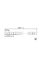
- FIG. 16 is a diagram illustrating a relationship between a hyper frame, a radio frame, and a sub frame.
- one radio frame (Radio frame) is composed of 10 subframes (Subframe).
- Subframes are identified by subframe numbers from 0 to 9.
- One hyper frame is composed of 1024 radio frames.
- the radio frame is identified by system frame numbers (SFN: System Frame Number) from 0 to 1023.
- the hyper frame is identified by a hyper frame number (H-SFN: Hyper System Frame Number). Each cell broadcasts the current H-SFN.
- ENB 200 transmits an MBMS signal to UE 100 via SC-MCCH or SC-MTCH.
- the MBMS signal includes at least one of MBMS control information (SC-PTM setting information) transmitted via SC-MCCH and MBMS data transmitted via SC-MTCH.
- eNB200 (control part 230) notifies the period information which shows the period which UE100 should monitor a MBMS signal to UE100.
- This period is an SC-MTCH scheduling period in which SC-MTCH is scheduled.
- this period is an SC-MCCH modification period in which the content of MBMS control information transmitted via the SC-MCCH can be changed.
- the period has a time length equal to or longer than a hyperframe including a plurality of radio frames.
- the period may have a time length that is an integral multiple of the hyperframe.
- the period information is used by the UE 100 to determine a hyperframe number (H-SFN) for monitoring the MBMS signal.
- H-SFN hyperframe number
- the UE 100 (control unit 130) according to the second embodiment intermittently monitors the MBMS signal transmitted from the eNB 200 via the SC-MCCH or SC-MTCH.
- UE100 (reception part 110) receives the period information which shows the period which should monitor an MBMS signal from eNB200.
- the UE 100 (control unit 130) determines a hyperframe number (H-SFN) for monitoring the MBMS signal based on the period information.
- H-SFN hyperframe number
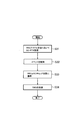
- FIG. 17 is a diagram illustrating an example of an operation flow of the UE 100 according to the second embodiment.
- the UE 100 receives, from the eNB 200, period information indicating a period for monitoring the MBMS signal.
- the period has a time length that is an integral multiple of the hyperframe.
- the UE 100 determines a hyperframe number (H-SFN) for monitoring the MBMS signal based on the period information.
- the UE 100 (control unit 130) determines the hyperframe number (H-SFN) to be monitored for the MBMS signal based on the identifier (TMGI) of the MBMS service received by the UE 100 or interested in reception and the period information.
- TMGI identifier
- step S23 the UE 100 (control unit 130) determines a frame number (SFN) and / or a subframe number for monitoring the MBMS signal in the determined hyper frame number (H-SFN).
- UE100 control part 130 may determine the hyper frame number and frame number which should monitor an MBMS signal based on period information.
- the UE 100 (control unit 130) may determine a frame number (SFN) for monitoring the SC-MCCH according to the parameter in the SIB 20.
- UE100 (control part 130) may determine the sub-frame number which should monitor SC-MTCH according to the parameter in SC-MCCH.
- step S24 the UE 100 (control unit 130) monitors (and receives) the MBMS signal in the determined radio frame number and / or subframe in the hyperframe.
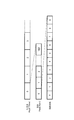
- FIG. 18 is a diagram showing an operation pattern 1 of the second embodiment.
- the operation pattern 1 of the second embodiment is a pattern for setting an SC-MTCH scheduling period (SC-MTCH scheduling period) in units of hyperframes.
- the UE 100 receives an SC-MTCH scheduling period (M) from the eNB 200.
- the SC-MTCH scheduling period (M) may be included in BCCH (SIB20) or SC-MCCH (SC-MCCH information).
- the SC-MTCH scheduling period (M) may be associated with TMGI.
- BCCH (SIB20) or SC-MCCH (SC-MCCH information) may include a TMGI list and an SC-MTCH scheduling period (M) associated with each TMGI.
- “current H-SFN” is the current H-SFN broadcast from the eNB 200.
- TMGI is an identifier of an MBMS service that the UE 100 is receiving or interested in receiving.
- M is a scheduling period of SC-MTCH belonging to the MBMS service received by UE 100 or interested in reception, and is an integral multiple of the hyperframe.
- step S203 the UE 100 determines that the SC-MTCH is not scheduled in the current H-SFN, and does not monitor the SC-MTCH (ie, sleeps).
- the UE 100 monitors the SC-MTCH in the current H-SFN in the step S204.
- the UE 100 (control unit 130) may determine the frame number (SFN) and / or the subframe number for monitoring the SC-MTCH according to the parameters in the SC-MCCH.
- FIG. 19 is a diagram showing an operation pattern 2 of the second embodiment.
- the operation pattern 2 of the second embodiment is a pattern for setting an SC-MCCH modification period (SC-MCCH modification period) in units of hyperframes.
- the UE 100 receives an SC-MCCH change period (M) from the eNB 200.
- the SC-MCCH change period (M) may be included in BCCH (SIB20) or SC-MCCH (SC-MCCH information).
- the SC-MCCH change period (M) may be associated with TMGI.
- BCCH (SIB20) or SC-MCCH (SC-MCCH information) may include a list of TMGIs and an SC-MCCH change period (M) associated with each TMGI.
- the SC-MCCH change period (M) may ignore the conventional sc-mcch-Modification Period (that is, the SC-MCCH change period for each radio frame) in the BCCH (SIB 20).
- “current H-SFN” is the current H-SFN broadcast from the eNB 200.
- “M” is the SC-MCCH scheduling period and is an integer multiple of the hyperframe. “M” may be the SC-MCCH scheduling period belonging to the MBMS service that the UE 100 is receiving or interested in receiving.
- step S213 the UE 100 determines that the current H-SFN is not the boundary of the SC-MCCH change period, and may not monitor the SC-MCCH (ie, sleep). ).
- the UE 100 determines that the current H-SFN is the boundary of the SC-MCCH change period, and monitors the SC-MCCH.
- the UE 100 (control unit 130) may determine the SFN determined by “SFN mod (TMGI mod 1024)” in the current H-SFN as the boundary of the SC-MCCH change period.
- TMGI is an identifier of the MBMS service that the UE 100 is receiving or interested in receiving.
- the UE 100 (control unit 130) may determine the frame number (SFN) and / or the subframe number for monitoring the SC-MCCH according to the parameters in the BCCH (SIB 20).
- FIG. 20 is a diagram showing an operation pattern 3 according to the second embodiment.
- the operation pattern 3 of the second embodiment is a pattern obtained by partially changing the operation pattern 2 of the second embodiment.
- the UE 100 receives an SC-MCCH change period (M) from the eNB 200.
- the SC-MCCH change period (M) may be included in BCCH (SIB20) or SC-MCCH (SC-MCCH information).
- the SC-MCCH change period (M) may be associated with TMGI.
- BCCH (SIB20) or SC-MCCH (SC-MCCH information) may include a list of TMGIs and an SC-MCCH change period (M) associated with each TMGI.
- M is an SC-MCCH scheduling period and is an integer multiple of a radio frame, but a value of 1024 or more (that is, a time of one hyperframe or more) may be set. “M” may be the SC-MCCH scheduling period belonging to the MBMS service that the UE 100 is receiving or interested in receiving.
- TMGI is an identifier of an MBMS service that the UE 100 is receiving or interested in receiving.
- the UE 100 determines that the current H-SFN and the current SFN are not boundaries of the SC-MCCH change period, and may not monitor the SC-MCCH ( That is, sleep).
- the UE 100 determines that the current H-SFN and the current SFN are boundaries of the SC-MCCH change period, and monitors the SC-MCCH.
- the third embodiment will be described mainly with respect to differences from the first and second embodiments. As in the first and second embodiments, the third embodiment mainly assumes a case where the UE 100 in the RRC idle state receives an MBMS service distributed by SC-PTM.
- the UE 100 may be a new category of UE described above.
- UE 100 receives MBMS data from eNB 200 via SC-MTCH in the RRC idle state.
- the UE 100 (control unit 130) transitions from the RRC idle state to the RRC connected state in response to the occurrence of an event that should transition to the RRC connected state during reception of MBMS data.
- UE100 (transmission part 120) transmits the identifier (TMGI) of the MBMS service corresponding to the MBMS data which UE100 has received in RRC idle state to eNB200, after changing to a RRC connected state.
- TMGI identifier
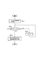
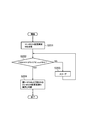
- FIG. 21 is a diagram illustrating an example of an operation flow of the UE 100 according to the third embodiment.
- the UE 100 receives MBMS data from the eNB 200 via the SC-MTCH in the RRC idle state.
- UE100 (control part 130) detects the event which should change to a RRC connected state during reception of MBMS data. Such an event may be an event that a paging is received or an event that a signaling needs to be transmitted.
- the UE 100 (control unit 130) transitions from the RRC idle state to the RRC connected state.
- UE100 transmission part 120
- TMGI identifier
- the UE 100 may always prioritize the operation related to unicast. For example, when data to be transmitted by unicast occurs, the UE 100 prioritizes the data transmission and interrupts the SC-PTM reception operation if necessary (for example, if simultaneous processing is not possible). Good.
- FIG. 22 is a diagram showing an operation pattern 1 of the third embodiment.
- UE100 transmits the request signal which requests
- the request signal includes an identifier (TMGI) of the MBMS service corresponding to the MBMS data received by the UE 100 in the RRC idle state.
- UE100 receives the MBMS data transmitted by unicast from eNB200 in a RRC connected state.
- the eNB 200 transmits MBMS data via SC-MTCH.
- the MBMS data is data belonging to a predetermined MBMS service.
- UE 100 receives MBMS data via SC-MTCH in the RRC idle state.
- the eNB 200 stores MBMS data transmitted via SC-MTCH in its own buffer in association with TMGI. Further, the eNB 200 may associate data identifiers such as HARQ process IDs and RLC sequence numbers with the stored MBMS data.
- step S302 the UE 100 detects an event that should transition to the RRC connected state.
- step S303 the UE 100 interrupts SC-PTM reception in response to the event detection.
- step S304 the UE 100 establishes an RRC connection with the eNB 200 by transmitting an RRC connection request message to the eNB 200, and transitions to the RRC connected state.
- the UE 100 in the RRC connected state transmits to the eNB 200 a NACK (retransmission request) for requesting retransmission of MBMS data that has not been received due to the interruption of SC-PTM reception.
- the NACK may be transmitted by an RRC message, an RLC Control PDU (Protocol Data Unit), or a MAC CE (Control Element).
- the NACK includes an MBMS service identifier (TMGI) corresponding to the MBMS data received by the UE 100 in the RRC idle state.
- the NACK may include an identifier (HARQ process ID, RLC sequence number, etc.) of the last received or unreceived data.
- ENB 200 specifies MBMS data for which UE 100 requests retransmission based on NACK.
- the eNB 200 reads the MBMS data from its own buffer.
- the eNB 200 transmits the MBMS data read from the buffer to the UE 100 via the DTCH.
- DTCH is a logical channel for unicast transmission. Thereafter, the UE 100 receives MBMS data by unicast in the RRC connected state.
- FIG. 23 is a diagram showing an operation pattern 2 of the third embodiment.
- the UE 100 (reception unit 110) continues to receive MBMS data from the eNB 200 via the SC-MTCH even when transitioning to the RRC connected state.
- step S311 the eNB 200 transmits MBMS data via SC-MTCH.
- the MBMS data is data belonging to a predetermined MBMS service.
- UE 100 receives MBMS data via SC-MTCH in the RRC idle state.
- step S312 the UE 100 detects an event that should transition to the RRC connected state.
- the UE 100 may detect the event or continue the SC-PTM reception without interruption.
- step S313 the UE 100 establishes an RRC connection with the eNB 200 by transmitting an RRC connection request message to the eNB 200, and transitions to the RRC connected state.
- the UE 100 in the RRC connected state notifies the eNB 200 of the TMGI of the SC-PTM being received.
- the UE 100 may include TMGI in an MBMS interest indication (MBMS Interest Indication) that is one of RRC messages.
- the MBMS interest notification is a message indicating that MBMS is being received or interested in reception. By including a flag indicating that MBMS is actually received in the MBMS interest notification, it may be simply indicated that the state is not interested in reception (not received state).
- UE100 may include TMGI in RLC Control PDU or MAC CE.
- the UE 100 may notify the eNB 200 of the attribute (distribution method) of the MBMS service being received.
- the attributes (distribution method) of the MBMS service include download (Downloading delivery method), streaming (Streaming delivery method), group communication (Group communication delivery method), and the like.
- the eNB 200 performs scheduling so that the UE 100 can appropriately receive SC-PTM transmission (multicast) and unicast transmission to the UE 100 based on the notification from the UE 100 (and the capability of the UE 100, etc.). As an example, the eNB 200 does not schedule SC-PTM transmission and unicast transmission to the UE 100 in the same subframe. Alternatively, the eNB 200 schedules SC-PTM transmission and unicast transmission to the UE 100 in the adjacent RB (Resource Block) or the same NB (Narrow Band). Further, the eNB 200 may schedule SC-PTM transmission with priority over unicast transmission to the UE 100 in one subframe.
- SC-PTM transmission multicast
- unicast transmission to the UE 100 based on the notification from the UE 100 (and the capability of the UE 100, etc.
- the eNB 200 does not schedule SC-PTM transmission and unicast transmission to the UE 100 in the same subframe.
- the eNB 200 schedules SC-PTM
- the eNB 200 may temporarily buffer data for unicast.
- the network can retransmit the same data as the already transmitted multicast data during the MBMS session (or during the file distribution session). While such retransmission data contributes to increasing the certainty of data delivery, a UE that has already received the data may receive duplicate unnecessary data and control information related thereto. . Therefore, the base station notifies the UE when the data retransmission is performed in the next modification period. The UE that has received the notification and has already received the data may not acquire the data (and the control information).
- the UE receives an SC-MCCH change notification by paging (or DCI masked with P-RNTI) has not been described.
- DRX intermittent paging monitoring
- the UE must monitor the SC-MCCH change notification more than the actual number of paging monitors, which increases power consumption. There is a risk of it.
- the UE is exempted from receiving operation for each SC-MCCH modification period.
- the SC-MCCH modification period (boundary) exempted from reception may be specified using the information for specifying the monitoring unnecessary period described above.
- the network may continue to transmit the notification for a predetermined period.
- an MBMS scenario using SC-PTM is mainly assumed, but an MBMS scenario using MBSFN may be assumed.
- SC-PTM may be read as MBSFN
- SC-MCCH may be read as MCCH
- SC-MTCH may be read as MTCH.
- firmware distribution is assumed as the MBMS service.
- group message distribution, group chat message distribution, virus definition file distribution, periodic update file distribution such as weather forecast, irregular file distribution such as breaking news, night file distribution such as video content (off-peak distribution), MBMS services such as audio / video streaming distribution, telephone / video telephone (group communication), live video distribution, and radio audio distribution may be assumed.
- the LTE system is exemplified as the mobile communication system.
- the present invention is not limited to LTE systems.
- the present invention may be applied to a mobile communication system other than the LTE system.
- SFN is represented by 10 bits, that is, the upper limit is 1024. Therefore, some of the existing values defined in sc-mcch-ModificationPeriod do not actually function, that is, rf2048 (20.48 [s]) to rf65536 (10.92 [min]).
- Proposal 1 When Proposal 1 is valid, especially when the same SC-MCCH is used for FeMTC UE and Release 13 SC-PTM UE, it is necessary to consider a method of ensuring backward compatibility. As discussed in Consideration 1, if the Release 13 UE is configured with a value greater than rf1024, there is no change boundary. However, in Release 13 SC-PTM, an important communication use case was assumed (but not limited to), which is a completely different use case of Release 14 FeMTC. Therefore, RAN2 should discuss whether backward compatibility is required for setting the SC-MCCH change period. If necessary, there are several simple solutions, such as defining a new IE-Release 14 SC-MCCH change period to allow multiple SC-MCCHs for Release 13/14 separation, etc. Exists.
- Proposal 2 If Proposal 1 is satisfactory, RAN2 needs to further consider whether and how to ensure backward compatibility of SC-MCCH change period settings.
- SC-MCCH change period ie, rf65536 (10.92 [minutes]
- SC-MCCH change notification is available, ie, PDCCH scrambled with SC-N-RNTI at SC-MCCH opportunity in Release 13 To monitor.
- SC-MCCH change boundary should be extended with 43.69 [min] and 2.91 [H].
- Proposal 3 The SC-MCCH change cycle should be extended to 43.69 minutes and 2.91 hours to match the upper limit of eDRX.
- the repeat period defined in Release 13 is to meet the access latency requirement.
- one of the main use cases in Release 14 multicast is considered firmware update, ie delay tolerance.
- one of the main motivations for iterating was to allow a UE to participate in an ongoing session if the UE joins late.
- this was mainly for streaming delivery, eg MCPTT.
- the main use of this WI is for firmware download transmission.
- the repetition time can be extended with little impact on the intended use case.
- the network assumes that the SC-MTCH can start transmitting after the corresponding SC-MCCH transmission is complete, eg after the next change boundary. .
- Proposal 3 it is beneficial to further extend the repetition period to rf65536 (10.92 minutes), rf262144 (43.69 [minutes]) or rf1048576 (2.91 [H]). It is.
- Proposal 4 The SC-MCCH repetition period should be extended to match the upper limit of the SC-MCCH change period as an optimization for delay tolerance applications.
- FIG. 27 shows SC-MCCH repetition periods (other than CE PDSCH repetition).
- RAN level start / stop time information In addition to current information, RAN level start / stop time information, ie, USD, assumes that some use cases that consider firmware delivery scheduling are the responsibility of the eNB in the AS layer. For example, if several UEs are interested in both TMGIs, the eNB may want to send different firmware files with different TMGIs in a TDD manner. In this case, the exact start / stop times are different between the two files, and it is beneficial for the UE to know when to start / stop delivery in order to save battery consumption.
- Existing MBSFN has means for providing RAN level stop time information to MAC CE, ie, MCH scheduling information MAC control element, in order to provide dynamic scheduling information for UE power saving. At that time, the reason for introducing only the “stop” information was “start” derived from the “stop” information. However, it applies only to MCH (ie MBSFN).
- SC-MTCH is assumed to use dynamic scheduling (ie M / NPDCCH), because RAN2 has a flexible SC-MTCH mechanism scheduled by PDCCH.
- SC-MCCH for feMTC and NB-IoT is dynamically scheduled and reused for multicast in NB-IoT and MTC to achieve secure scheduling.
- both SC-MCCH and SC-MTCH may be scheduled on anchor and / or non-anchor carriers for NB-IoT, where SC-MCCH and SC-MTCH are NB-IoT and MTC ( Narrowband MTC) may be scheduled with different carriers.
- Unnecessary Wakeup (eg UE interested in TMGI # 5), from the UE perspective when SC-MTCH serving the TMGI interested is delivered Unpredictable and consumes UE battery due to wakeup in each SC-MTCH scheduling period. Therefore, it is useful to introduce start / stop time information for efficient multicast.
- start / stop time information can be applied to prevent unnecessary wake-up for SC-MCCH monitoring (in addition to / in place of SC-MTCH monitoring).
- Proposal 5 RAN level start / stop information should be provided to save UE power.
- Proposal 5 is acceptable, the question is which signaling carries the information (ie MAC CE or RRC message).
- MAC CE Radio Resource Control
- RRC message eg SC-MCCH.
- Proposal 6 If Proposal 5 is acceptable, RAN2 should consider whether “start” information is provided by the RRC message and “stop” information is provided by the MAC CE.
- RAN2 assumes that a direct indication or similar mechanism that provides DCI information can be used for SC-MCCH change notification.
- RAN2 also has a practical assumption that MT (paging) and SC-PTM: MT (paging) has a higher priority than SC-PTM.
- the paging opportunity is a good opportunity for all notifications consistent with the Release 13 direct indication.
- both the paging monitor and notification check situations can be adjusted. Therefore, the RNTI of the SC-MCCH change notification must be P-RNTI.
- Proposal 7 P-RNTI should be used for SC-MCCH change notification This is in the reserved bits of 8 bits of TS 36.331 Table 6.6-1 and Table 6.7.5-1. This is the simplest method for completely reusing the existing direct indication by assigning “SC-MCCH change notification” to A single notification is sufficient for SC-MCCH changes.
- TMGI-specific change notification using DCI for SC-MTCH scheduling has been proposed. If it is assumed that the content of the SC-MCCH is changed frequently, it actually allows more scheduling flexibility (between the SC-MCCH and SC-MTCH) and does not require a UE. Avoid getting.
- TMGI specific SC-MCCH change notification would be beneficial if the SC-MCCH is expected to change frequently.
- Send LS to RAN2-RAN1 informs RAN2 that the maximum number of ongoing SC-MTCHs supported by SC-MCCH has decreased compared to LTE, Request RAN2 to inform RAN1 of the maximum number of SC-MTCHs in progress supported by SC-MCCH in FeMTC; Requests RAN2 to inform RAN1 how SC-MCCH segmentation is supported in Release 14.
- the maximum number of ongoing SC-MTCHs supported on SC-MCCH is less than on LTE.
- Send LS to RAN2-RAN1 informs RAN2 that the maximum number of ongoing SC-MTCHs supported by SC-MCCH has decreased compared to LTE, Request RAN2 to notify RAN1 of the maximum number of ongoing SC-MTCHs supported by SC-MCCH in NB-IoT; -Increase the maximum TBS value further, Requests RAN2 to inform RAN1 whether and how SC-MCCH segmentation is supported in Release 14 and how it is segmented.
- the current RAN1 should reduce the number of services, that is, SC-MTCH configurable on SC-MCCH compared to LTE, but there are multiple SC-MCCHs per cell. Did not exclude the possibility of existing. If it is necessary to support many services at the same time, the principle of one SC-MCCH per cell may not be sufficient.
- SIB20 would indicate the SC-MCCH carrier and SC-MCCH would indicate the MTCH carrier. This statement seems to apply only to eNB-IoT, but FeMTC also seems to have that intention. Therefore, for confirmation only, RAN2 is asked to discuss whether it has been agreed that “SIB 20 indicates SC-MCCH NB and SC-MCCH indicates SC-MTCH NB”.
- Proposal 8 It was confirmed that SIB20 shows the narrow band of SC-MCCH and SC-MCCH shows the narrow band of SC-MTCH.
- SC-MCCH provides information on service continuity in order for the UE to easily find interesting MBMS services being served on other frequencies / cells.
- the SCPTM-NeighbourCellList includes a cell ID and a frequency
- the sc-mtch-neighbourCell for each TMGI indicates in the bit string whether each entry of the list provides an MBMS service (see FIG. 29). .
- SIB15 provides similar information, but mainly targeted MBSFN.
- an MBMS-SAI-List including an MBMS service area ID is provided for the intra frequency, and is provided for the inter frequency together with the dl-CarrierFreq.
- SC-MCCH Compared to SIB15, SC-MCCH added a cell ID to the service continuity information in order to change the granularity from multi-cell broadcast (or single frequency network) to single-cell PTM. Therefore, accurate information on which resources provide the MBMS service of interest is useful for service continuity (and UE battery consumption during cell reselection) in Release 13.
- Release 13 wideband, Release 14 narrowband Coverage Release 13 normal coverage and Release 14 coverage enhancement Use cases (but not limited to): Release 13 MCPTT and firmware / software updates, and Release 14 Group message delivery
- RAN2 should discuss whether it is necessary to enhance service continuity for each change.
- Option 1 Indicates whether MBMS service is provided to narrowband / carrier.
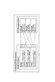
- SC-MTCH-InfoList As shown in FIG.
- sc-mtch-neighbourCell-BL indicates whether SC-MTCH is provided in a narrow band (ie, 6 PRBs)
- sc-mch-neighborCell-NB indicates that SC-MTCH is a carrier (ie, 1 PRB).
- Option 2 Specify the narrow band / carrier on which the MBMS service is provided.
- the SC-MCCH has information such as where the MBMS service is provided in the neighboring cell, as in the RAN2 agreement that “SIB20 indicates the SC-MCCH carrier and SC-MCCH indicates the carrier”. It is also useful to provide. However, since it can be assumed that it can be configured somewhat dynamically within the system bandwidth, it may be difficult for the eNB to provide similar information under FeMTC, i.e. a narrowband in which MBMS services are provided. For example, as shown in FIG. 31, it can be mounted on the SCPTM-NeighbourCellList. However, NarrowbandOperation indicates whether SC-PTM is provided in a narrow band (ie, 6 PRBs), and carrierFreqOffset indicates whether an anchor carrier (ie, one PRB) provides SC-PTM.
- Option 1 For FeMTC UE, these options are very similar, but for eNB-IoT UE there are some differences.
- Option 1 the UE needs to search which carrier provides SC-PTM in neighboring cells, and Option 2 facilitates smoother movement.
- option 2 if multiple anchor carriers broadcast multiple (different) SIBs 20, option 2 causes additional overhead (multiple IEs, eg lists may be required).
- Proposal 1 RAN2 should discuss whether SC-PTM narrowband operation in neighboring cells should be provided.
- Proposal 2 RAN2 should allow neighboring cells to provide SC-PTM coverage information (eg repeat count, power boost level and MCS, or some integrated threshold / offset for reliability check) by the serving cell Whether or not should be discussed.
- SC-PTM coverage information eg repeat count, power boost level and MCS, or some integrated threshold / offset for reliability check
- Release 13 eg, streaming
- Release 14 eg, file delivery
- Packet delivery is not synchronized between eNBs in the network.
- the upper layer mechanism, FLUTE compensates for packet loss in the AS layer, for example by unicast file recovery.
- lossless mobility may depend on several higher layer mechanisms of Release 14 multicast.
- the amount of packet loss such as a missing FLUTE block depends on several AS layer configurations, eg, synchronous delivery, SIB20 scheduling periodicity, SC-MCCH repetition period, etc. This affects, for example, the number and residence time of RRC connection requests in RRC connection requests for unicast file recovery and causes additional UE power consumption.
- the method of minimizing packet loss depends on the implementation of the NW.
Landscapes
- Engineering & Computer Science (AREA)
- Computer Networks & Wireless Communication (AREA)
- Signal Processing (AREA)
- Multimedia (AREA)
- Mobile Radio Communication Systems (AREA)
Abstract
無線端末は、基地局からSC-MCCHを介して送信されるMBMS制御情報を間欠的に監視する制御部と、前記SC-MCCHを介して送信されるMBMS制御情報の内容が変更され得るSC-MCCH変更周期を示す情報を前記基地局から受信する受信部と、を備える。前記SC-MCCH変更周期は、複数の無線フレームからなるハイパーフレーム以上の時間長を有する。前記制御部は、前記SC-MCCH変更周期に基づいて、SC-MCCH変更境界に対応するハイパーフレーム番号及びフレーム番号を、(1024×H-SFN+SFN) mod M = 0により決定する。前記「H-SFN」は前記SC-MCCH変更境界に対応するハイパーフレーム番号を示し、前記「SFN」は前記SC-MCCH変更境界に対応するフレーム番号を示し、前記「M」は前記SC-MCCH変更周期を示す。
Description
本発明は、移動通信システムのための無線端末及び基地局に関する。
移動通信システムの標準化プロジェクトである3GPP(Third Generation Partnership Project)において、無線端末にマルチキャスト/ブロードキャストサービスを提供するMBMS(Multimedia Broadcast Multicast Service)伝送が仕様化されている。MBMSの方式としては、MBSFN(Multicast Broadcast Single Frequency Network)及びSC-PTM(Single Cell Point-To-Multipoint)の2つの方式がある。
一方、人が介在することなく通信を行うMTC(Machine Type Communication)やIoT(Internet of Things)サービスを対象とした無線端末が検討されている。このような無線端末は、低コスト化、カバレッジ広域化、及び低消費電力化を実現することが求められる。このため、3GPPにおいて、システム送受信帯域の一部のみに送受信帯域幅を制限した新たな無線端末のカテゴリが仕様化されている。このような新たなカテゴリの無線端末には、繰り返し送信(repetition)等を含む強化カバレッジ(enhanced coverage)機能が適用される。
一実施形態に係る無線端末は、SC-PTMを用いたMBMS伝送をサポートする移動通信システムのための無線端末である。無線端末は、基地局からSC-MCCHを介して送信されるMBMS制御情報を間欠的に監視する制御部と、前記SC-MCCHを介して送信されるMBMS制御情報の内容が変更され得るSC-MCCH変更周期を示す情報を前記基地局から受信する受信部と、を備える。前記SC-MCCH変更周期は、複数の無線フレームからなるハイパーフレーム以上の時間長を有する。前記制御部は、前記SC-MCCH変更周期に基づいて、SC-MCCH変更境界に対応するハイパーフレーム番号及びフレーム番号を、(1024×H-SFN+SFN) mod M = 0により決定する。前記「H-SFN」は前記SC-MCCH変更境界に対応するハイパーフレーム番号を示し、前記「SFN」は前記SC-MCCH変更境界に対応するフレーム番号を示し、前記「M」は前記SC-MCCH変更周期を示す。
一実施形態に係る基地局は、SC-PTMを用いたMBMS伝送をサポートする移動通信システムのための基地局である。基地局は、SC-MCCHを介してMBMS制御情報を無線端末に送信する送信部と、前記SC-MCCHを介して送信されるMBMS制御情報の内容が変更され得るSC-MCCH変更周期を示す情報を前記無線端末に通知する制御部と、を備える。前記SC-MCCH変更周期は、複数の無線フレームからなるハイパーフレーム以上の時間長を有する。SC-MCCH変更境界は、(1024×H-SFN+SFN) mod M = 0により決定される。前記「H-SFN」は前記SC-MCCH変更境界に対応するハイパーフレーム番号を示し、前記「SFN」は前記SC-MCCH変更境界に対応するフレーム番号を示し、前記「M」は前記SC-MCCH変更周期を示す。
一実施形態に係る無線端末は、SC-PTMを用いたMBMS伝送をサポートする移動通信システムのための無線端末である。無線端末は、基地局からSC-MTCHを介してMBMSサービスを受信する受信部と、制御部と、を備える。前記受信部は、前記SC-MTCHを介した前記MBMSサービスの送信の停止を示すMAC CEを前記基地局から受信する。前記制御部は、前記MAC CEの受信に応じて、前記SC-MTCHを介した前記MBMSサービスの送信が停止されると判断する。
一実施形態に係る基地局は、SC-PTMを用いたMBMS伝送をサポートする移動通信システムのための基地局である。基地局は、SC-MTCHを介してMBMSサービスを送信する送信部を備える。前記送信部は、さらに、前記SC-MTCHを介した前記MBMSサービスの送信の停止を示すMAC CEを前記無線端末に送信する。
(移動通信システム)
実施形態に係る移動通信システムの構成について説明する。実施形態に係る移動通信システムは、3GPPで仕様が策定されているLTE(Long Term Evolution)システムである。図1は、実施形態に係るLTEシステムの構成を示す図である。図2は、MBMSに係るネットワーク構成を示す図である。
実施形態に係る移動通信システムの構成について説明する。実施形態に係る移動通信システムは、3GPPで仕様が策定されているLTE(Long Term Evolution)システムである。図1は、実施形態に係るLTEシステムの構成を示す図である。図2は、MBMSに係るネットワーク構成を示す図である。
図1に示すように、LTEシステムは、無線端末(UE:User Equipment)100、無線アクセスネットワーク(E-UTRAN:Evolved-UMTS Terrestrial Radio Access Network)10、及びコアネットワーク(EPC:Evolved Packet Core)20を備える。E-UTRAN10及びEPC20は、LTEシステムのネットワークを構成する。
UE100は、移動型の通信装置であり、自身が在圏するセル(サービングセル)を管理するeNB200との無線通信を行う。
E-UTRAN10は、基地局(eNB:evolved Node-B)200を含む。eNB200は、X2インターフェイスを介して相互に接続される。eNB200は、1又は複数のセルを管理しており、自セルとの接続を確立したUE100との無線通信を行う。eNB200は、無線リソース管理(RRM)機能、ユーザデータ(以下、単に「データ」という)のルーティング機能、モビリティ制御・スケジューリングのための測定制御機能等を有する。「セル」は、無線通信エリアの最小単位を示す用語として用いられる。セルは、UE100との無線通信を行う機能又はリソースを示す用語としても用いられる。
EPC20は、モビリティ管理エンティティ(MME)及びサービングゲートウェイ(S-GW)300を含む。MMEは、UE100に対する各種モビリティ制御等を行う。S-GWは、データの転送制御を行う。MME/S-GW300は、S1インターフェイスを介してeNB200と接続される。
次に、MBMS向けのネットワークエンティティについて説明する。E-UTRAN10は、MCE(Multi-Cell/Multicast Coordinating Entity)11を含む。MCE11は、M2インターフェイスを介してeNB200と接続され、M3インターフェイスを介してMME300と接続される(図2参照)。MCE11は、MBSFN無線リソース管理・割当等を行う。具体的には、MCE11は、MBSFNのスケジューリングを行う。これに対し、SC-PTMのスケジューリングはeNB200により行われる。
EPC20は、MBMS GW(MBMS Gateway)21を含む。MBMS GW21は、M1インターフェイスを介してeNB200と接続され、Smインターフェイスを介してMME300と接続され、SG-mb及びSGi-mbインターフェイスを介してBM-SC22と接続される(図2参照)。MBMS GW21は、eNB200に対してIPマルチキャストのデータ伝送及びセッション制御等を行う。
また、EPC20は、BM-SC(Broadcast Multicast Service Center)22を含む。BM-SC22は、SG-mb及びSGi-mbインターフェイスを介してMBMS GW21と接続され、SGiインターフェイスを介してP-GW23と接続される(図2参照)。BM-SC22は、TMGI(Temporary Mobile Group Identity)の管理・割当等を行う。
さらに、EPC20の外部のネットワーク(すなわち、インターネット)には、GCS AS(Group Communication Service Application Server)31が設けられてもよい。GCS AS31は、グループ通信用のアプリケーションサーバである。GCS AS31は、MB2-U及びMB2-Cインターフェイスを介してBM-SC22と接続され、SGiインターフェイスを介してP-GW23と接続される。GCS AS31は、グループ通信におけるグループの管理及びデータ配信等を行う。
図3は、実施形態に係るUE100(無線端末)の構成を示す図である。図3に示すように、UE100は、受信部110、送信部120、及び制御部130を備える。
受信部110は、制御部130の制御下で各種の受信を行う。受信部110は、アンテナ及び受信機を含む。受信機は、アンテナが受信する無線信号をベースバンド信号(受信信号)に変換して制御部130に出力する。
送信部120は、制御部130の制御下で各種の送信を行う。送信部120は、アンテナ及び送信機を含む。送信機は、制御部130が出力するベースバンド信号(送信信号)を無線信号に変換してアンテナから送信する。
制御部130は、UE100における各種の制御を行う。制御部130は、プロセッサ及びメモリを含む。メモリは、プロセッサにより実行されるプログラム、及びプロセッサによる処理に用いられる情報を記憶する。プロセッサは、ベースバンド信号の変調・復調及び符号化・復号等を行うベースバンドプロセッサと、メモリに記憶されるプログラムを実行して各種の処理を行うCPU(Central Processing Unit)と、を含む。プロセッサは、音声・映像信号の符号化・復号を行うコーデックを含んでもよい。プロセッサは、後述する各種の処理を実行する。
図4は、実施形態に係るeNB200(基地局)の構成を示す図である。図4に示すように、eNB200は、送信部210、受信部220、制御部230、及びバックホール通信部240を備える。
送信部210は、制御部230の制御下で各種の送信を行う。送信部210は、アンテナ及び送信機を含む。送信機は、制御部230が出力するベースバンド信号(送信信号)を無線信号に変換してアンテナから送信する。
受信部220は、制御部230の制御下で各種の受信を行う。受信部220は、アンテナ及び受信機を含む。受信機は、アンテナが受信する無線信号をベースバンド信号(受信信号)に変換して制御部230に出力する。
制御部230は、eNB200における各種の制御を行う。制御部230は、プロセッサ及びメモリを含む。メモリは、プロセッサにより実行されるプログラム、及びプロセッサによる処理に用いられる情報を記憶する。プロセッサは、ベースバンド信号の変調・復調及び符号化・復号等を行うベースバンドプロセッサと、メモリに記憶されるプログラムを実行して各種の処理を行うCPUと、を含む。プロセッサは、後述する各種の処理を実行する。
バックホール通信部240は、X2インターフェイスを介して隣接eNBと接続され、S1インターフェイスを介してMME/S-GW300と接続される。バックホール通信部240は、X2インターフェイス上で行う通信及びS1インターフェイス上で行う通信等に用いられる。バックホール通信部240は、M1インターフェイス上で行う通信及びM2インターフェイス上で行う通信にも用いられ得る。
図5は、LTEシステムにおける無線インターフェイスのプロトコルスタックを示す図である。図5に示すように、無線インターフェイスプロトコルは、OSI参照モデルの第1レイヤ乃至第3レイヤに区分されており、第1レイヤは物理(PHY)レイヤである。第2レイヤは、MAC(Medium Access Control)レイヤ、RLC(Radio Link Control)レイヤ、及びPDCP(Packet Data Convergence Protocol)レイヤを含む。第3レイヤは、RRC(Radio Resource Control)レイヤを含む。
物理レイヤは、符号化・復号、変調・復調、アンテナマッピング・デマッピング、及びリソースマッピング・デマッピングを行う。UE100の物理レイヤとeNB200の物理レイヤとの間では、物理チャネルを介してデータ及び制御信号が伝送される。
MACレイヤは、データの優先制御、HARQ(Hybrid ARQ)による再送処理等を行う。UE100のMACレイヤとeNB200のMACレイヤとの間では、トランスポートチャネルを介してデータ及び制御信号が伝送される。eNB200のMACレイヤは、スケジューラを含む。スケジューラは、上下リンクのトランスポートフォーマット(トランスポートブロックサイズ、変調・符号化方式(MCS))、及びUE100への割当リソースブロックを決定する。
RLCレイヤは、MACレイヤ及び物理レイヤの機能を利用してデータを受信側のRLCレイヤに伝送する。UE100のRLCレイヤとeNB200のRLCレイヤとの間では、論理チャネルを介してデータ及び制御信号が伝送される。
PDCPレイヤは、ヘッダ圧縮・伸張、及び暗号化・復号化を行う。
RRCレイヤは、制御信号を取り扱う制御プレーンでのみ定義される。UE100のRRCレイヤとeNB200のRRCレイヤとの間では、各種設定のためのメッセージ(RRCメッセージ)が伝送される。RRCレイヤは、無線ベアラの確立、再確立及び解放に応じて、論理チャネル、トランスポートチャネル、及び物理チャネルを制御する。UE100のRRCとeNB200のRRCとの間に接続(RRC接続)がある場合、UE100はRRCコネクティッド状態であり、そうでない場合、UE100はRRCアイドル状態である。
RRCレイヤの上位に位置するNAS(Non-Access Stratum)レイヤは、セッション管理及びモビリティ管理等を行う。
図6は、LTEシステムの下りリンクのチャネルの構成を示す図である。図6(a)は、論理チャネル(Downlink Logical Channel)とトランポートチャネル(Downlink Transport Channel)との間のマッピングを示す。
図6(a)に示すように、PCCH(Paging Control Channel)は、ページング情報、及びシステム情報変更を通知するための論理チャネルである。PCCHは、トランスポートチャネルであるPCH(Paging Channel)にマッピングされる。
BCCH(Broadcast Control Channel)は、システム情報のための論理チャネルである。BCCHは、トランスポートチャネルであるBCH(Broadcast Control Channel)及びDL-SCH(Downlink Shared Channel)にマッピングされる。
CCCH(Common Control Channel)は、UE100とeNB200との間の送信制御情報のための論理チャネルである。CCCHは、UE100がネットワークとの間でRRC接続を有していない場合に用いられる。CCCHは、DL-SCHにマッピングされる。
DCCH(Dedicated Control Channel)は、UE100とネットワークとの間の個別制御情報を送信するための論理チャネルである。DCCHは、UE100がRRC接続を有する場合に用いられる。DCCHは、DL-SCHにマッピングされる。
DTCH(Dedicated Traffic Channel)は、データ送信のための個別論理チャネルである。DTCHは、DL-SCHにマッピングされる。
SC-MTCH(Single Cell Multicast Traffic Channel)は、SC-PTMのための論理チャネルである。SC-MTCHは、SC-PTMを用いてネットワークからUE100にデータ(MBMS)をマルチキャスト送信するための1対多チャネル(point-to-multipoint downlink channel)である。
SC-MCCH(Single Cell Multicast Control Channel)は、SC-PTMのための論理チャネルである。SC-MCCHは、1又は複数のSC-MTCHのためのMBMS制御情報をネットワークからUE100にマルチキャスト送信するための1対多チャネル(point-to-multipoint downlink channel)である。SC-MCCHは、SC-PTMを用いてMBMSを受信する又は受信に興味を持つUE100に用いられる。また、SC-MCCHは、1つのセルに1つのみ存在する。
MCCH(Multicast Control Channel)は、MBSFNのための論理チャネルである。MCCHは、ネットワークからUE100へのMTCH用のMBMS制御情報の送信のために用いられる。MCCHは、トランスポートチャネルであるMCH(Multicast Channel)にマッピングされる。
MTCH(Multicast Traffic Channel)は、MBSFNのための論理チャネルである。MTCHは、MCHにマッピングされる。
図6(b)は、トランポートチャネル(Downlink Transport Channel)と物理チャネル(Downlink Physical Channel)との間のマッピングを示す。
図6(b)に示すように、BCHは、PBCH(Physical Broadcast Channel)にマッピングされる。
MCHは、PMCH(Physical Multicast Channel)にマッピングされる。MCHは、複数のセルによるMBSFNをサポートする。
PCH及びDL-SCHは、PDSCH(Physical Downlink Shared Channel)にマッピングされる。DL-SCHは、HARQ、リンクアダプテーション、及び動的リソース割当をサポートする。
PDCCHは、PDSCH(DL-SCH、PCH)のリソース割り当て情報及びDL-SCHに関するHARQ情報等を運搬する。また、PDCCHは、上りリンクのスケジューリンググラントを運ぶ。
図7は、LTEシステムの無線フレームの構成を示す図である。LTEシステムにおいて、下りリンクにはOFDMA(Orthogonal Frequency Division Multiple Access)、上りリンクにはSC-FDMA(Single Carrier Frequency Division Multiple Access)がそれぞれ適用される。
図7に示すように、無線フレームは、時間方向に並ぶ10個のサブフレームで構成される。各サブフレームは、時間方向に並ぶ2個のスロットで構成される。各サブフレームの長さは1msであり、各スロットの長さは0.5msである。各サブフレームは、周波数方向に複数個のリソースブロック(RB)を含み、時間方向に複数個のシンボルを含む。各リソースブロックは、周波数方向に複数個のサブキャリアを含む。1つのシンボル及び1つのサブキャリアにより1つのリソースエレメント(RE)が構成される。また、UE100に割り当てられる無線リソース(時間・周波数リソース)のうち、周波数リソースはリソースブロックにより特定でき、時間リソースはサブフレーム(又はスロット)により特定できる。
下りリンクにおいて、各サブフレームの先頭数シンボルの区間は、主に下りリンク制御信号を伝送するためのPDCCHとして用いられる領域である。また、各サブフレームの残りの部分は、主に下りリンクデータを伝送するためのPDSCHとして使用できる領域である。また、下りリンクにおいて、MBSFN向けのサブフレームであるMBSFNサブフレームが設定され得る。
上りリンクにおいて、各サブフレームにおける周波数方向の両端部は、主に上りリンク制御信号を伝送するためのPUCCHとして用いられる領域である。各サブフレームにおける残りの部分は、主に上りリンクデータを伝送するためのPUSCHとして使用できる領域である。
(SC-PTMの概要)
次に、SC-PTMの概要について説明する。MBMS用の無線伝送方式としては、MBSFN及びSC-PTMの2つの方式がある。MBSFNにおいては、複数のセルからなるMBSFNエリア単位で、PMCHを介してデータが送信される。これに対し、SC-PTMにおいては、セル単位で、PDSCHを介してデータが送信される。以下においては、UE100がSC-PTM受信を行うシナリオを主として想定するが、MBSFNを想定してもよい。
次に、SC-PTMの概要について説明する。MBMS用の無線伝送方式としては、MBSFN及びSC-PTMの2つの方式がある。MBSFNにおいては、複数のセルからなるMBSFNエリア単位で、PMCHを介してデータが送信される。これに対し、SC-PTMにおいては、セル単位で、PDSCHを介してデータが送信される。以下においては、UE100がSC-PTM受信を行うシナリオを主として想定するが、MBSFNを想定してもよい。
UE100は、RRCコネクティッド状態でMBMSサービスを受信してもよいし、RRCアイドル状態でMBMSサービスを受信してもよい。以下において、UE100がRRCアイドル状態でMBMSサービスを受信するケースを主として想定する。
図8は、SC-PTMの動作例を示す図である。
図8に示すように、ステップS1において、UE100は、eNB200を介してEPC20からUSD(User Service Description)を取得する。USDは、各MBMSサービスの基本的な情報を提供する。USDは、MBMSサービスごとに、当該MBMSサービスを識別するTMGIと、当該MBMSサービスが提供される周波数と、当該MBMSサービスの提供開始・終了時間と、を含む。
ステップS2において、UE100は、BCCHを介してeNB200からSIB20を受信する。SIB20は、SC-MCCHの取得に必要な情報(スケジューリング情報)を含む。図9は、SIB20を示す図である。図9に示すように、SIB20は、SC-MCCHの内容が変更され得る周期を示すsc-mcch-ModificationPeriod、SC-MCCHの送信(再送)周期を無線フレーム数で示すsc-mcch-RepetitionPeriod、SC-MCCHがスケジュールされる無線フレームのオフセットを示すsc-mcch-Offset、及びSC-MCCHがスケジュールされるサブフレームを示すsc-mcch-Subframe等を含む。
ステップS3において、UE100は、SIB20に基づいて、SC-MCCHを介してeNB200からMBMS制御情報を受信する。MBMS制御情報は、SC-PTM設定情報(SCPTM Configuration)と称されてもよい。物理レイヤにおいてSC-MCCHの送信にはSC-RNTI(Single Cell RNTI)が用いられる。図10は、SC-MCCH中のMBMS制御情報(SC-PTM設定情報)を示す図である。図10に示すように、SC-PTM設定情報は、SC-MRB(Single Cell MBMS Point to Multipoint Radio Bearer)を介して送信されるMBMSサービスに適用可能な制御情報を含む。SC-PTM設定情報は、当該情報を送信するセルにおける各SC-MTCHの設定を含むsc-mtch-InfoList、及びSC-MRBを介してMBMSサービスを提供する隣接セルのリストであるscptmNeighbourCellListを含む。sc-mtch-InfoListは、1又は複数のSC-MTCH-Infoを含む。各SC-MTCH-Infoは、SC-MRBを介して送信される進行中のMBMSセッションの情報(mbmsSessionInfo)、当該MBMSセッションに対応するG-RNTI(Group RNTI)、及びSC-MTCHのためのDRX情報であるsc-mtch-schedulingInfoを含む。mbmsSessionInfoは、MBMSサービスを識別するTMGI及びセッションID(sessionId)を含む。G-RNTIは、マルチキャストグループ(具体的には、特定グループ宛てのSC-MTCH)を識別するRNTIである。G-RNTIは、TMGIと1対1でマッピングされる。sc-mtch-schedulingInfoは、onDurationTimerSCPTM、drx-InactivityTimerSCPTM、schedulingPeriodStartOffsetSCPTMを含む。schedulingPeriodStartOffsetSCPTMは、SC-MTCH-SchedulingCycle及びSC-MTCH-SchedulingOffsetを含む。
ステップS4において、UE100は、SC-PTM設定情報中のSC-MTCH-SchedulingInfoに基づいて、SC-MTCHを介して、自身が興味のあるTMGIに対応するMBMSサービス(MBMSデータ)を受信する。物理レイヤにおいて、eNB200は、G-RNTIを用いてPDCCHを送信した後、PDSCHを介してMBMSデータを送信する。
なお、図8に関連して説明した制御信号(シグナリング)は一例であり、省電力受信のための最適化等により、一部の制御信号が適宜省略されたり、制御信号の順序が入れ替わったりしてもよい。
(eMTC及びNB-IoTの概要)
次に、eMTC及びNB-IoTの概要について説明する。実施形態において、新たなカテゴリのUE100が存在するシナリオを想定する。新たなカテゴリのUE100は、システム送受信帯域の一部のみに送受信帯域幅が制限されるUE100である。新たなUEカテゴリは、例えば、カテゴリM1及びNB(Narrow Band)-IoTカテゴリと称される。ここで、カテゴリM1は、eMTC(enhanced Machine Type Communications)UEである。また、NB-IoT UEは、カテゴリNB1である。カテゴリM1は、UE100の送受信帯域幅を1.08MHz(すなわち、6リソースブロックの帯域幅)に制限するとともに、繰り返し送信等を用いた強化カバレッジ(EC:Enhanced Coverage)機能をサポートする。NB-IoTカテゴリは、UE100の送受信帯域幅を180kHz(すなわち、1リソースブロックの帯域幅)にさらに制限するとともに、強化カバレッジ機能をサポートする。繰り返し送信は、複数のサブフレームを用いて同一の信号を繰り返し送信する技術である。一例として、LTEシステムのシステム帯域幅は10MHzであり、そのうちの送受信帯域幅は9MHz(すなわち、50リソースブロックの帯域幅)である。一方、カテゴリM1のUE100は、6リソースブロックよりも広い帯域幅で送信される下りリンク無線信号を受信することができないため、通常のPDCCHを受信することができない。このため、MTC向けのPDCCHであるMPDCCH(MTC-PDCCH)が導入される。同様な理由で、NB-IoT向けのPDCCHであるNPDCCH(NB-PDCCH)が導入される。
次に、eMTC及びNB-IoTの概要について説明する。実施形態において、新たなカテゴリのUE100が存在するシナリオを想定する。新たなカテゴリのUE100は、システム送受信帯域の一部のみに送受信帯域幅が制限されるUE100である。新たなUEカテゴリは、例えば、カテゴリM1及びNB(Narrow Band)-IoTカテゴリと称される。ここで、カテゴリM1は、eMTC(enhanced Machine Type Communications)UEである。また、NB-IoT UEは、カテゴリNB1である。カテゴリM1は、UE100の送受信帯域幅を1.08MHz(すなわち、6リソースブロックの帯域幅)に制限するとともに、繰り返し送信等を用いた強化カバレッジ(EC:Enhanced Coverage)機能をサポートする。NB-IoTカテゴリは、UE100の送受信帯域幅を180kHz(すなわち、1リソースブロックの帯域幅)にさらに制限するとともに、強化カバレッジ機能をサポートする。繰り返し送信は、複数のサブフレームを用いて同一の信号を繰り返し送信する技術である。一例として、LTEシステムのシステム帯域幅は10MHzであり、そのうちの送受信帯域幅は9MHz(すなわち、50リソースブロックの帯域幅)である。一方、カテゴリM1のUE100は、6リソースブロックよりも広い帯域幅で送信される下りリンク無線信号を受信することができないため、通常のPDCCHを受信することができない。このため、MTC向けのPDCCHであるMPDCCH(MTC-PDCCH)が導入される。同様な理由で、NB-IoT向けのPDCCHであるNPDCCH(NB-PDCCH)が導入される。
図11は、eMTC UE向けの下りリンク物理チャネルを示す図である。図11に示すように、eNB200は、6リソースブロック以内でMPDCCHを送信する。MPDCCHは、PDSCHを割り当てるためのスケジューリング情報を含む。一例として、MPDCCHは、当該MPDCCHが送信されるサブフレームとは異なるサブフレームのPDSCHを割り当てる。eNB200は、6リソースブロック以内でPDSCHを送信する。また、eNB200は、同一の信号の繰り返し送信を行うために、複数のサブフレームに亘ってPDSCHを割り当てる。カテゴリM1のUE100は、MPDCCHを受信することで割り当てPDSCHを特定し、割り当てPDSCHで送信されるデータを受信する。
図12は、eMTC UE及びNB-IoT UE向けのランダムアクセスプロシージャを示す図である。図12の初期状態において、UE100は、RRCアイドル状態にある。UE100は、RRCコネクティッド状態に遷移するためにランダムアクセスプロシージャを実行する。
UE100は、eNB200のセルをサービングセルとして選択している。UE100は、通常のカバレッジのための第1のセル選択基準(第1のS-criteria)が満たされず、強化カバレッジのための第2のセル選択基準(第2のS-criteria)が満たされた場合、自身が強化カバレッジに居ると判定してもよい。「強化カバレッジに居るUE」とは、セルにアクセスするために強化カバレッジ機能(強化カバレッジモード)を用いることが必要とされるUEを意味する。なお、eMTC UEは、強化カバレッジモードを用いることが必須である。
図12に示すように、ステップS1001において、eNB200は、PRACH(Physical Random Access Channel)関連情報をブロードキャストシグナリング(例えば、SIB)により送信する。PRACH関連情報は、強化カバレッジレベルごとに設けられた各種のパラメータを含む。一例として、強化カバレッジレベルは、強化カバレッジレベル0乃至3の合計4つのレベルが規定される。各種のパラメータは、RSRP(Reference Signal Received Power)閾値、PRACHリソース、及び最大プリアンブル送信回数を含む。PRACHリソースは、無線リソース(時間・周波数リソース)及び信号系列(プリアンブル系列)を含む。UE100は、受信したPRACH関連情報を記憶する。
ステップS1002において、UE100は、eNB200から送信される参照信号に基づいてRSRPを測定する。
ステップS1003において、UE100は、測定したRSRPを強化カバレッジレベルごとのRSRP閾値と比較することにより、自身の強化カバレッジレベルを決定する。強化カバレッジレベルは、UE100に必要とされる強化カバレッジの度合いを示す。強化カバレッジレベルは、少なくとも繰り返し送信における送信回数(すなわち、Repetition回数)と関連する。
ステップS1004において、UE100は、自身の強化カバレッジレベルに対応するPRACHリソースを選択する。
ステップS1005において、UE100は、選択したPRACHリソースを用いてMsg 1(ランダムアクセスプリアンブル)をeNB200に送信する。eNB200は、受信したMsg 1に用いられたPRACHリソースに基づいて、UE100の強化カバレッジレベルを特定する。
ステップS1006において、eNB200は、UE100に割り当てたPUSCHリソースを示すスケジューリング情報を含むMsg 2(ランダムアクセス応答)をUE100に送信する。なお、UE100は、Msg 2を正常に受信するまで、自身の強化カバレッジレベルに対応する最大プリアンブル送信回数までMsg 1を複数回送信し得る。
ステップS1007において、UE100は、スケジューリング情報に基づいて、Msg 3をeNB200に送信する。Msg 3は、RRC Connection Requestメッセージであってもよい。
ステップS1008において、eNB200は、Msg 4をUE100に送信する。
ステップS1009において、UE100は、Msg 4の受信に応じてRRCコネクティッド状態に遷移する。その後、eNB200は、特定した強化カバレッジレベルに基づいて、UE100への繰り返し送信等を制御する。
(第1実施形態)
上述したような移動通信システムを前提として、以下において、第1実施形態について説明する。第1実施形態は、RRCアイドル状態のUE100に対して、SC-PTMを用いたMBMSによりファームウェア等の一括配信を行うシナリオを想定する。UE100は、上述した新たなカテゴリのUEであってもよい。
上述したような移動通信システムを前提として、以下において、第1実施形態について説明する。第1実施形態は、RRCアイドル状態のUE100に対して、SC-PTMを用いたMBMSによりファームウェア等の一括配信を行うシナリオを想定する。UE100は、上述した新たなカテゴリのUEであってもよい。
第1実施形態において、eNB200(送信部210)は、SC-MCCH又はSC-MTCHを介してMBMS信号を周期的にUE100に送信する。MBMS信号は、SC-MCCHを介して送信されるMBMS制御情報(SC-PTM設定情報)及びSC-MTCHを介して送信されるMBMSデータの少なくとも1つを含む。SC-MCCH及びSC-MTCHは、SC-PTM用の論理チャネルである。eNB200(制御部230)は、UE100がMBMS信号を受信すべき将来のタイミングを示す通知情報をUE100に通知する。監視不要期間は、MBMS信号の送信周期よりも長い時間長を有してもよい。UE100(制御部130)は、eNB200からSC-MCCH又はSC-MTCHを介して周期的に送信されるMBMS信号を監視する。UE100(受信部110)は、通知情報をeNB200から受信する。UE100(制御部130)は、通知情報に基づいて、MBMS信号の監視を省略可能な監視不要期間を特定する。UE100(制御部130)は、監視不要期間においてMBMS信号の監視を省略することができるため、SC-PTM受信に伴うUE100の消費電力を削減することができる。
なお、第1実施形態において、eNB200(送信部210)は、自身のカバレッジを強化するための強化カバレッジ機能を用いてMBMS信号を送信してもよい。また、MBMSサービス(TMGI)ごとに強化カバレッジのレベルが異なってもよい。強化カバレッジ機能は、同一信号を繰り返し送信する繰り返し送信(Repetition)を含んでもよい。繰り返し送信の回数が多いほど、カバレッジを強化することができる。強化カバレッジ機能は、送信信号の電力密度を上げる電力ブースト(Power boosting)を含んでもよい。一例として、送信信号の周波数帯域幅を狭くする狭帯域送信により電力密度を上げる。送信信号の電力密度を上げるほど、カバレッジを強化することができる。強化カバレッジ機能は、送信信号に用いるMCSを下げる低MCS(Lower MCS)送信を含んでもよい。データレートが低く、誤り耐性の高いMCSを用いて送信を行うことにより、カバレッジを強化することができる。
図13は、第1実施形態に係るUE100の動作フロー例を示す図である。図13に示すように、ステップS11において、UE100(受信部110)は、UE100がMBMS信号を受信すべき将来のタイミングを示す通知情報をeNB200から受信する。通知情報は、MBMSサービスの識別子(TMGI)と対応付けられていてもよい。ステップS12において、UE100(制御部130)は、通知情報に基づいて監視不要期間を特定する。UE100(制御部130)は、自身が受信している又は受信に興味を持つMBMSサービスに対応する監視不要期間を特定してもよい。ステップS13において、UE100(制御部130)は、監視不要期間においてMBMS信号の監視を省略する。ステップS14において、UE100は、監視不要期間の経過後に、MBMS信号を監視し、MBMS信号をeNB200から受信する。
図14は、第1実施形態の動作パターン1を示す図である。第1実施形態の動作パターン1において、通知情報は、SC-MCCHを介して送信されるMBMS制御情報(以下、「SC-MCCH情報」と称する)の内容が変更される将来のタイミングを示す情報を含む。監視不要期間は、SC-MCCH情報の内容が変更される将来のタイミングまでの期間である。第1実施形態の動作パターン1に係る監視不要期間を「SC-MCCH監視不要期間」と称する。
図14(a)に示すように、eNB200は、SC-MCCHを介してSC-MCCH情報を周期的に送信する。SC-MCCH情報の送信周期(Repetition Period)は、SIB20中のパラメータであるsc-mcch-RepetitionPeriodにより設定され、無線フレームの整数倍である。また、eNB200は、SC-MCCH変更周期(SC-MCCH modification period)の境界において、SC-MCCH情報を変更し得る。SC-MCCH変更周期は、SIB20中のパラメータであるsc-mcch-ModificationPeriodにより設定され、無線フレームの整数倍である。図14に示す例において、時刻t0~t6の区間が1つのSC-MCCH変更周期に相当し、時刻t6~t12の区間が次のSC-MCCH変更周期に相当する。
eNB200は、SC-MCCH変更周期内で、送信周期(Repetition Period)ごとに同一のSC-MCCH情報を送信し得る。eNB200は、あるSC-MCCH変更周期のSC-MCCH情報を変更する場合、当該SC-MCCH変更周期内でSC-MCCHに用いられる所定のサブフレームにおいて変更通知(change notification)をUE100に送信する。SC-PTM受信に興味を持つUE100は、eNB200から変更通知を受信すると、当該SC-MCCH変更周期内で新たなSC-MCCH情報を取得する。UE100は、新たなSC-MCCH情報を取得するまでは、既に取得した以前のSC-MCCH情報を適用する。SC-MCCH情報が変更されない場合には、UE100は、SC-MCCHの監視を省略する(例えば、受信機をオフにする)ことにより、消費電力を削減することができる。
しかしながら、このような変更通知(change notification)を用いる方法では、UE100は、各SC-MCCH変更周期内で少なくとも1回は受信を行う必要がある。
第1実施形態の動作パターン1において、eNB200(制御部230)は、SC-MCCH情報が次に変更されるタイミングを示すタイミング情報を含む通知情報をUE100に通知する。eNB200(制御部230)は、BCCH(SIB20)に通知情報を含めてもよいし、SC-MCCH(SC-MCCH情報)に通知情報を含めてもよい。タイミング情報は、SC-MCCH情報の変更タイミングを直接的に示す情報であってもよいし、現在のタイミングを基準として当該変更タイミングを相対的に示す情報であってもよい。タイミング情報は、無線フレーム(SFN:System Frame Number)単位、ハイパーフレーム(H-SFN:Hyper System Frame Number)単位、又はSC-MCCH変更周期単位で指定されてもよい。UE100は、通知情報を受信したタイミングから当該変更タイミングまでの期間をSC-MCCH監視不要期間として特定する。
図14に示す例において、eNB200は、時刻t0~t6のSC-MCCH変更周期内の最初のタイミング(時刻t0~t1)で通知情報をUE100に通知する。通知情報は、次のSC-MCCH変更周期の経過後にSC-MCCH情報を変更する旨のタイミング情報を含む。図14(b)に示すように、UE100は、時刻t0~t1のタイミングにおいて通知情報を受信すると、当該タイミング(時刻t1)から次のSC-MCCH変更周期の終了タイミング(時刻t12)までの期間をSC-MCCH監視不要期間として特定し、当該SC-MCCH監視不要期間においてSC-MCCHの監視を省略する。よって、UE100は、時刻t6~t12のSC-MCCH変更周期内でSC-MCCHの監視を1回も行わなくて済む。UE100は、SC-MCCH監視不要期間が経過したタイミング(時刻t12~t13)でSC-MCCHを監視する。
eNB200は、MBMSサービス(TMGI)ごとに通知情報をUE100に通知してもよい。この場合、eNB200は、通知情報中でTMGIごとにタイミング情報を通知してもよい。通知情報は、所定のMBMSサービスに対応するTMGIと、当該所定のMBMSサービスに対応するSC-MCCH情報が次に変更されるタイミングを示すタイミング情報とを含む。通知情報は、TMGIのリストと、各TMGIに対応付けられたタイミング情報とを含んでもよい。UE100は、通知情報を受信すると、自身が受信している又は受信に興味を持つMBMSサービス(TMGI)に対応するタイミング情報を通知情報から取得し、取得したタイミング情報に基づいてSC-MCCH監視不要期間を特定する。
第1実施形態の動作パターン1において、SC-MCCHが同一セルに複数設けられるシナリオを想定してもよい。この場合、各SC-MCCHが1又は複数のMBMSサービス(TMGI)と対応付けられてもよい。各SC-MCCHに適用される強化カバレッジのレベルが異なってもよい。複数のTMGIに対応するSC-MCCHが存在する場合、TMGIごとにSC-MCCH変更周期を異ならせてもよい。一例として、eNB200は、TMGIと対応付けたSC-MCCH変更周期をSIB20中でUE100に通知する。SIB20は、TMGIのリストと、各TMGIに対応付けられたSC-MCCH変更周期とを含んでもよい。UE100は、SIB20を受信すると、自身が受信している又は受信に興味を持つMBMSサービス(TMGI)に対応するSC-MCCH変更周期をSIB20から取得し、取得したSC-MCCH変更周期に基づいてSC-MCCH監視不要期間を特定する。
図15は、第1実施形態の動作パターン2を示す図である。
図15(b)に示すように、eNB200は、SC-MTCHを周期的にスケジューリングする。SC-MTCHのスケジューリング周期(Cycle)及びスケジューリング開始オフセット(Start offset)は、SC-MCCH中のパラメータであるschedulingPeriodStartOffsetSCPTMにより設定され、サブフレームの整数倍である。通常、UE100は、スケジューリング周期(Cycle)ごとに、オン持続時間(On duration)の間はSC-MTCHを監視する。オン持続時間は、SC-MCCH中のパラメータであるonDurationTimerSCPTMにより設定され、サブフレームの整数倍である。UE100は、オン持続時間内で、自身宛のPDCCHが下りリンク送信をスケジューリングすることを検知した場合、所定時間の間はオン状態を維持し、SC-MTCHの監視を継続する。当該所定時間は、SC-MCCH中のパラメータであるdrx-InactivityTimerSCPTMにより設定され、サブフレームの整数倍である。このように、UE100は、SC-MCCH中のパラメータに従ってSC-MTCHを間欠的に監視する。このような動作は、SC-PTMのための間欠受信(DRX:Discontinuous Reception)と称される。
しかしながら、このようなDRXを用いる方法では、UE100は、スケジューリング周期(Cycle)ごとにSC-MTCHの監視を行う必要がある。
図15(a)に示す例において、eNB200は、SC-MCCHを介して、SC-MCCH送信タイミング(時刻t0~t1)で通知情報をUE100に通知する。通知情報は、所定の無線フレーム(SFN)の経過後にSC-MTCHをスケジューリングする旨のタイミング情報を含む。通知情報は、監視を省略すべきスケジューリング周期の数(N cycles)を示してもよい。監視不要期間は、MBMSデータがスケジューリングされる将来のタイミングまでの期間である。第1実施形態の動作パターン2に係る監視不要期間を「SC-MTCH監視不要期間」と称する。
eNB200(制御部230)は、SC-MCCH(SC-MCCH情報)に通知情報を含める。或いは、eNB200(制御部230)は、BCCH(SIB20)に通知情報を含めてもよい。タイミング情報は、SC-MTCH情報のスケジューリングタイミングを直接的に示す情報であってもよいし、現在のタイミングを基準として当該スケジューリングタイミングを相対的に示す情報であってもよい。タイミング情報は、無線フレーム(SFN)単位、ハイパーフレーム(H-SFN)単位、サブフレーム単位、スケジューリング周期単位で指定されてもよい。
図15(c)に示すように、UE100は、時刻t0~t1のタイミングにおいて通知情報を受信すると、当該タイミング(時刻t1)からSC-MTCHスケジューリングタイミング(時刻t8)までの期間をSC-MTCH監視不要期間として特定し、当該SC-MTCH監視不要期間においてSC-MTCHの監視を省略する。よって、UE100は、時刻t1~t8の間はSC-MTCHの監視を1回も行わなくて済む。UE100は、SC-MTCH監視不要期間が経過したタイミングのオン持続時間(時刻t8~t9)でSC-MTCHを監視する。また、UE100は、オン持続時間(時刻t8~t9)中に、自身宛の下りリンク送信のスケジューリングを示すPDCCHを検知し、時刻t10までSC-MTCHの監視を継続する。
eNB200は、MBMSサービス(TMGI)ごとに通知情報をUE100に通知してもよい。この場合、eNB200は、通知情報中でTMGIごとにタイミング情報を通知してもよい。通知情報は、所定のMBMSサービスに対応するTMGIと、当該所定のMBMSサービスに対応するSC-MTCHが次にスケジューリングされるタイミングを示すタイミング情報とを含む。通知情報は、TMGIのリストと、各TMGIに対応付けられたタイミング情報とを含んでもよい。UE100は、通知情報を受信すると、自身が受信している又は受信に興味を持つMBMSサービス(TMGI)に対応するタイミング情報を通知情報から取得し、取得したタイミング情報に基づいてSC-MTCH監視不要期間を特定する。
第1実施形態の動作パターン2において、eNB200(制御部230)は、SC-MTCH(MBMSデータ)がスケジューリングされる将来のタイミングを示す通知情報をUE100に通知する。当該将来のタイミングは、SC-MTCHのスケジューリング開始タイミング(すなわち、UE100がSC-MTCHの監視を開始すべきタイミング)とみなすことができる。さらに、eNB200(制御部230)は、通知情報中で、SC-MTCH(MBMSデータ)のスケジューリングが終了される将来のタイミングを示してもよい。このような終了タイミングは、SC-MTCHのスケジューリング終了タイミングを直接的に示す情報であってもよいし、スケジューリング開始タイミングを基準として当該スケジューリング終了タイミングを相対的に示す情報(期間情報)であってもよい。スケジューリング終了タイミングの情報は、無線フレーム(SFN)単位、ハイパーフレーム(H-SFN)単位、サブフレーム単位、スケジューリング周期単位で指定されてもよい。UE100は、スケジューリング開始タイミングからスケジューリング終了タイミングまでの期間をSC-MTCH監視必要期間として特定する。
(第2実施形態)
第2実施形態について、第1実施形態との相違点を主として説明する。第2実施形態は、第1実施形態と同様に、RRCアイドル状態のUE100がSC-PTMにより配信されるMBMSサービスを受信するケースを主として想定する。UE100は、上述した新たなカテゴリのUEであってもよい。
第2実施形態について、第1実施形態との相違点を主として説明する。第2実施形態は、第1実施形態と同様に、RRCアイドル状態のUE100がSC-PTMにより配信されるMBMSサービスを受信するケースを主として想定する。UE100は、上述した新たなカテゴリのUEであってもよい。
第1実施形態において、SC-MCCHが無線フレーム単位でスケジューリングされ、SC-MTCHがサブフレーム単位でスケジューリングされる一例を説明した。第2実施形態においては、SC-MCCH/SC-MTCHがハイパーフレーム単位でスケジューリングされる。UE100は、SC-MCCH/SC-MTCHがスケジューリングされないハイパーフレームにおいてSC-MCCH/SC-MTCHの監視を省略することができる。
図16は、ハイパーフレーム、無線フレーム、及びサブフレームの関係を示す図である。図16に示すように、1つの無線フレーム(Radio frame)は、10個のサブフレーム(Subframe)により構成される。サブフレームは、0番から9番までのサブフレーム番号により識別される。1つのハイパーフレーム(Hyper frame)は、1024個の無線フレームにより構成される。無線フレームは、0番から1023番までのシステムフレーム番号(SFN:System Frame Number)により識別される。ハイパーフレームは、ハイパーフレーム番号(H-SFN:Hyper System Frame Number)により識別される。各セルは、現在のH-SFNを報知する。
第2実施形態に係るeNB200(送信部210)は、SC-MCCH又はSC-MTCHを介してMBMS信号をUE100に送信する。MBMS信号は、SC-MCCHを介して送信されるMBMS制御情報(SC-PTM設定情報)及びSC-MTCHを介して送信されるMBMSデータの少なくとも1つを含む。eNB200(制御部230)は、UE100がMBMS信号を監視すべき周期を示す周期情報をUE100に通知する。当該周期は、SC-MTCHがスケジューリングされるSC-MTCHスケジューリング周期(SC-MTCH scheduling period)である。或いは、当該周期は、SC-MCCHを介して送信されるMBMS制御情報の内容が変更され得るSC-MCCH変更周期(SC-MCCH modification period)である。当該周期は、複数の無線フレームからなるハイパーフレーム以上の時間長を有する。当該周期は、ハイパーフレームの整数倍の時間長を有してもよい。周期情報は、MBMS信号を監視すべきハイパーフレーム番号(H-SFN)をUE100が決定するために用いられる。
第2実施形態に係るUE100(制御部130)は、eNB200からSC-MCCH又はSC-MTCHを介して送信されるMBMS信号を間欠的に監視する。UE100(受信部110)は、MBMS信号を監視すべき周期を示す周期情報をeNB200から受信する。UE100(制御部130)は、周期情報に基づいて、MBMS信号を監視すべきハイパーフレーム番号(H-SFN)を決定する。
図17は、第2実施形態に係るUE100の動作フロー例を示す図である。図17に示すように、ステップS21において、UE100(受信部110)は、MBMS信号を監視すべき周期を示す周期情報をeNB200から受信する。当該周期は、ハイパーフレームの整数倍の時間長を有する。ステップS22において、UE100(制御部130)は、周期情報に基づいて、MBMS信号を監視すべきハイパーフレーム番号(H-SFN)を決定する。UE100(制御部130)は、UE100が受信している又は受信に興味を持つMBMSサービスの識別子(TMGI)と周期情報とに基づいて、MBMS信号を監視すべきハイパーフレーム番号(H-SFN)を決定してもよい。ステップS23において、UE100(制御部130)は、決定したハイパーフレーム番号(H-SFN)内でMBMS信号を監視すべきフレーム番号(SFN)及び/又はサブフレーム番号を決定する。UE100(制御部130)は、周期情報に基づいて、MBMS信号を監視すべきハイパーフレーム番号及びフレーム番号を決定してもよい。UE100(制御部130)は、SIB20中のパラメータに従ってSC-MCCHを監視すべきフレーム番号(SFN)を決定してもよい。UE100(制御部130)は、SC-MCCH中のパラメータに従ってSC-MTCHを監視すべきサブフレーム番号を決定してもよい。ステップS24において、UE100(制御部130)は、決定したハイパーフレーム中の無線フレーム番号及び/又はサブフレームにおいてMBMS信号を監視(及び受信)する。
図18は、第2実施形態の動作パターン1を示す図である。第2実施形態の動作パターン1は、ハイパーフレーム単位でSC-MTCHスケジューリング周期(SC-MTCH scheduling period)を設定するパターンである。
図18に示すように、ステップS201において、UE100は、SC-MTCHスケジューリング周期(M)をeNB200から受信する。SC-MTCHスケジューリング周期(M)は、BCCH(SIB20)又はSC-MCCH(SC-MCCH情報)に含まれてもよい。SC-MTCHスケジューリング周期(M)は、TMGIと対応付けられていてもよい。BCCH(SIB20)又はSC-MCCH(SC-MCCH情報)は、TMGIのリストと、各TMGIに対応付けられたSC-MTCHスケジューリング周期(M)とを含んでもよい。
ステップS202において、UE100は、「現H-SFN mod M = TMGI mod M」が満たされるか否か判定する。ここで、「現H-SFN」は、eNB200から報知される現在のH-SFNである。「TMGI」は、UE100が受信している又は受信に興味を持つMBMSサービスの識別子である。「M」は、UE100が受信している又は受信に興味を持つMBMSサービスに属するSC-MTCHのスケジューリング周期であり、ハイパーフレームの整数倍である。
ステップS202で「NO」の場合、ステップS203において、UE100は、現在のH-SFNにおいて、SC-MTCHがスケジューリングされないと判断し、SC-MTCHを監視しない(すなわち、スリープする)。
一方、ステップS202で「YES」の場合、ステップS204において、UE100は、現在のH-SFNにおいてSC-MTCHを監視する。UE100(制御部130)は、SC-MCCH中のパラメータに従ってSC-MTCHを監視すべきフレーム番号(SFN)及び/又はサブフレーム番号を決定してもよい。
図19は、第2実施形態の動作パターン2を示す図である。第2実施形態の動作パターン2は、ハイパーフレーム単位でSC-MCCH変更周期(SC-MCCH modification period)を設定するパターンである。
図19に示すように、ステップS211において、UE100は、SC-MCCH変更周期(M)をeNB200から受信する。SC-MCCH変更周期(M)は、BCCH(SIB20)又はSC-MCCH(SC-MCCH情報)に含まれてもよい。SC-MCCH変更周期(M)は、TMGIと対応付けられていてもよい。BCCH(SIB20)又はSC-MCCH(SC-MCCH情報)は、TMGIのリストと、各TMGIに対応付けられたSC-MCCH変更周期(M)とを含んでもよい。UE100は、SC-MCCH変更周期(M)が通知される場合、BCCH(SIB20)中の従来のsc-mcch-ModificationPeriod(すなわち、無線フレーム単位のSC-MCCH変更周期)を無視してもよい。
ステップS212において、UE100は、「現H-SFN mod M = 0」が満たされるか否か判定する。ここで、「現H-SFN」は、eNB200から報知される現在のH-SFNである。「M」は、SC-MCCHのスケジューリング周期であり、ハイパーフレームの整数倍である。「M」は、UE100が受信している又は受信に興味を持つMBMSサービスに属するSC-MCCHのスケジューリング周期であってもよい。
ステップS212で「NO」の場合、ステップS213において、UE100は、現在のH-SFNがSC-MCCH変更周期の境界ではないと判断し、SC-MCCHを監視しなくてもよい(すなわち、スリープする)。
一方、ステップS212で「YES」の場合、ステップS214において、UE100は、現在のH-SFNがSC-MCCH変更周期の境界であると判断し、SC-MCCHを監視する。UE100(制御部130)は、現在のH-SFNにおける「SFN mod (TMGI mod 1024)」により定まるSFNをSC-MCCH変更周期の境界として決定してもよい。ここで、「TMGI」は、UE100が受信している又は受信に興味を持つMBMSサービスの識別子である。UE100(制御部130)は、BCCH(SIB20)中のパラメータに従ってSC-MCCHを監視すべきフレーム番号(SFN)及び/又はサブフレーム番号を決定してもよい。
図20は、第2実施形態の動作パターン3を示す図である。第2実施形態の動作パターン3は、第2実施形態の動作パターン2を一部変更したパターンである。
図20に示すように、ステップS221において、UE100は、SC-MCCH変更周期(M)をeNB200から受信する。SC-MCCH変更周期(M)は、BCCH(SIB20)又はSC-MCCH(SC-MCCH情報)に含まれてもよい。SC-MCCH変更周期(M)は、TMGIと対応付けられていてもよい。BCCH(SIB20)又はSC-MCCH(SC-MCCH情報)は、TMGIのリストと、各TMGIに対応付けられたSC-MCCH変更周期(M)とを含んでもよい。
ステップS222において、UE100は、「(1024×現H-SFN+現SFN) mod M = 0」が満たされるか否か判定する。ここで、「M」は、SC-MCCHのスケジューリング周期であり、無線フレームの整数倍であるが、1024以上の値(すなわち、1ハイパーフレーム以上の時間)が設定されてもよい。「M」は、UE100が受信している又は受信に興味を持つMBMSサービスに属するSC-MCCHのスケジューリング周期であってもよい。
或いは、ステップS222において、「(1024×現H-SFN+現SFN) mod M = 0」に代えて、「(1024×現H-SFN+現SFN) mod M = TMGI mod M」が満たされるか否か判定してもよい。「TMGI」は、UE100が受信している又は受信に興味を持つMBMSサービスの識別子である。
ステップS222で「NO」の場合、ステップS223において、UE100は、現在のH-SFN及び現在のSFNがSC-MCCH変更周期の境界ではないと判断し、SC-MCCHを監視しなくてもよい(すなわち、スリープする)。
一方、ステップS222で「YES」の場合、ステップS224において、UE100は、現在のH-SFN及び現在のSFNがSC-MCCH変更周期の境界であると判断し、SC-MCCHを監視する。
(第3実施形態)
第3実施形態について、第1及び第2実施形態との相違点を主として説明する。第3実施形態は、第1及び第2実施形態と同様に、RRCアイドル状態のUE100がSC-PTMにより配信されるMBMSサービスを受信するケースを主として想定する。UE100は、上述した新たなカテゴリのUEであってもよい。
第3実施形態について、第1及び第2実施形態との相違点を主として説明する。第3実施形態は、第1及び第2実施形態と同様に、RRCアイドル状態のUE100がSC-PTMにより配信されるMBMSサービスを受信するケースを主として想定する。UE100は、上述した新たなカテゴリのUEであってもよい。
第3実施形態に係るUE100(受信部110)は、RRCアイドル状態において、SC-MTCHを介してeNB200からMBMSデータを受信する。UE100(制御部130)は、MBMSデータの受信中に、RRCコネクティッド状態に遷移すべきイベントが生じたことに応じて、RRCアイドル状態からRRCコネクティッド状態に遷移する。UE100(送信部120)は、RRCコネクティッド状態に遷移した後、RRCアイドル状態においてUE100が受信していたMBMSデータに対応するMBMSサービスの識別子(TMGI)をeNB200に送信する。
図21は、第3実施形態に係るUE100の動作フロー例を示す図である。図21に示すように、ステップS31において、UE100(受信部110)は、RRCアイドル状態において、SC-MTCHを介してeNB200からMBMSデータを受信する。ステップS32において、UE100(制御部130)は、MBMSデータの受信中に、RRCコネクティッド状態に遷移すべきイベントを検知する。このようなイベントは、ページングを受信したというイベント、又はシグナリングを送信する必要が生じたというイベントであってもよい。ステップS33において、UE100(制御部130)は、RRCアイドル状態からRRCコネクティッド状態に遷移する。ステップS34において、UE100(送信部120)は、RRCアイドル状態においてUE100が受信していたMBMSデータに対応するMBMSサービスの識別子(TMGI)をeNB200に送信する。
第3実施形態において、UE100は、SC-PTM受信中にユニキャストに関するイベントが発生した場合には、必ずユニキャストに係る動作を優先して実施する事としてもよい。例えば、ユニキャストで伝送するデータが発生した場合には、UE100は当該データ送信を優先するとともに、必要であれば(例えば同時処理が不可能であれば)SC-PTM受信動作を中断してもよい。
図22は、第3実施形態の動作パターン1を示す図である。第3実施形態の動作パターン1において、UE100(送信部120)は、MBMSデータのユニキャスト再送を要求する要求信号をeNB200に送信する。要求信号は、RRCアイドル状態においてUE100が受信していたMBMSデータに対応するMBMSサービスの識別子(TMGI)を含む。UE100(受信部110)は、RRCコネクティッド状態において、eNB200からユニキャストで送信されるMBMSデータを受信する。
図22に示すように、ステップS301において、eNB200は、SC-MTCHを介してMBMSデータを送信する。当該MBMSデータは、所定のMBMSサービスに属するデータである。UE100は、RRCアイドル状態でSC-MTCHを介してMBMSデータを受信する。eNB200は、SC-MTCHを介して送信したMBMSデータをTMGIと対応付けて自身のバッファに蓄積する。さらに、eNB200は、蓄積するMBMSデータにHARQプロセスID、RLCシーケンス番号等のデータ識別子を対応付けてもよい。
ステップS302において、UE100は、RRCコネクティッド状態に遷移すべきイベントを検知する。ステップS303において、UE100は、イベントの検知に応じて、SC-PTM受信を中断する。ステップS304において、UE100は、RRC接続要求メッセージをeNB200に送信することによりeNB200とのRRC接続を確立し、RRCコネクティッド状態に遷移する。
ステップS305において、RRCコネクティッド状態のUE100は、SC-PTM受信の中断により未受信となったMBMSデータの再送を要求するためのNACK(再送要求)をeNB200に送信する。当該NACKは、RRCメッセージ、RLC Control PDU(Protocol Data Unit)、又はMAC CE(Control Element)で送信されてもよい。NACKは、RRCアイドル状態においてUE100が受信していたMBMSデータに対応するMBMSサービスの識別子(TMGI)を含む。NACKは、最後に受信した又は未受信のデータの識別子(HARQプロセスID、RLCシーケンス番号等)を含んでもよい。
eNB200は、NACKに基づいて、UE100が再送を要求するMBMSデータを特定する。eNB200は、自身のバッファから当該MBMSデータを読み出す。ステップS306において、eNB200は、DTCHを介して、バッファから読み出したMBMSデータをUE100に送信する。DTCHは、ユニキャスト送信用の論理チャネルである。以降、UE100は、RRCコネクティッド状態においてMBMSデータをユニキャストで受信する。
図23は、第3実施形態の動作パターン2を示す図である。第3実施形態の動作パターン2において、UE100(受信部110)は、RRCコネクティッド状態に遷移しても、SC-MTCHを介してeNB200からMBMSデータの受信を継続する。
図23に示すように、ステップS311において、eNB200は、SC-MTCHを介してMBMSデータを送信する。当該MBMSデータは、所定のMBMSサービスに属するデータである。UE100は、RRCアイドル状態でSC-MTCHを介してMBMSデータを受信する。
ステップS312において、UE100は、RRCコネクティッド状態に遷移すべきイベントを検知する。動作パターン2において、UE100は、イベントを検知しても、SC-PTM受信を中断せずに継続してもよい。ステップS313において、UE100は、RRC接続要求メッセージをeNB200に送信することによりeNB200とのRRC接続を確立し、RRCコネクティッド状態に遷移する。
ステップS314において、RRCコネクティッド状態のUE100は、受信中SC-PTMのTMGIをeNB200に通知する。UE100は、RRCメッセージの一つであるMBMS興味通知(MBMS Interest Indication)にTMGIを含めてもよい。MBMS興味通知は、MBMSを受信している又は受信に興味があることを示すメッセージである。実際にMBMSを受信していることを示すフラグをMBMS興味通知に含めることにより、単に受信に興味がある状態(未受信の状態)ではないことを示してもよい。或いは、UE100は、RLC Control PDU又はMAC CE等にTMGIを含めてもよい。
また、UE100は、受信中のMBMSサービスの属性(配信方法)をeNB200に通知してもよい。一例として、MBMSサービスの属性(配信方法)は、ダウンロード(Download delivery method)、ストリーミング(Streaming delivery method)、グループ通信(Group communication delivery method)等である。
ステップS315において、eNB200は、UE100からの通知(及びUE100の能力等)に基づいて、SC-PTM送信(マルチキャスト)及び当該UE100へのユニキャスト送信をUE100が適切に受信できるようにスケジューリングを行う。一例として、eNB200は、SC-PTM送信及びUE100へのユニキャスト送信を同一サブフレームにスケジューリングしない。或いは、eNB200は、SC-PTM送信及びUE100へのユニキャスト送信を隣接RB(Resource Block)又は同一NB(Narrow Band)にスケジューリングする。また、eNB200は、1つのサブフレームにおいてUE100へのユニキャスト送信よりもSC-PTM送信を優先してスケジューリングしてもよい。SC-PTM送信は複数UE宛てであるため、他UEへの影響を考えるとSC-PTMを優先することが好ましい。SC-PTM送信を優先する場合、eNB200は、ユニキャスト用のデータを一時的にバッファしてもよい。
(その他の実施形態)
ネットワーク(基地局等)は、MBMSセッション中(もしくはファイル配信セッション中)において、既にマルチキャスト送信済みのデータと同一のデータを、再度送信する事が可能である。このような再送データは、データ送達の確実性を高める事に寄与する一方、当該データを既に受信済みのUEにとっては、重複した不要なデータやこれに係る制御情報を受信してしまう虞がある。よって、基地局は、次回modification periodにおいて、当該データ再送が実施される場合に、UEに対して通知を行う。当該通知を受信し、既に当該データを受信済みのUEは、当該データ(及び係る制御情報)の取得を行わなくてもよい。
ネットワーク(基地局等)は、MBMSセッション中(もしくはファイル配信セッション中)において、既にマルチキャスト送信済みのデータと同一のデータを、再度送信する事が可能である。このような再送データは、データ送達の確実性を高める事に寄与する一方、当該データを既に受信済みのUEにとっては、重複した不要なデータやこれに係る制御情報を受信してしまう虞がある。よって、基地局は、次回modification periodにおいて、当該データ再送が実施される場合に、UEに対して通知を行う。当該通知を受信し、既に当該データを受信済みのUEは、当該データ(及び係る制御情報)の取得を行わなくてもよい。
上述した実施形態において、UEが、ページング(又はP-RNTIでマスクされたDCI)によって、SC-MCCHの変更通知(change notification)を受信する場合について述べていなかった。この場合、当該UEには更にDRX(ページングの間欠モニタ)が設定されている事が想定される。もし、SC-MCCH modification periodが当該DRXサイクル内に複数存在する場合、当該UEはSC-MCCH change notificationのモニタを、実際のページングモニタ回数よりも多く実施しなければならず、消費電力が上がってしまう虞がある。このような場合、UEは、SC-MCCH modification period毎の受信動作が免除される。例えば、上述した監視不要期間を特定する為の情報を用いて、受信が免除されるSC-MCCH modification period (boundary)を特定してもよい。もしくは、ネットワーク(基地局)は、ある所定の期間において当該notificationを送信し続けてもよい。
上述した各実施形態を別個独立に実施する場合に限らず、2以上の実施形態を組み合わせて実施してもよい。例えば、一の実施形態に係る一部の処理を他の実施形態に追加してもよい。或いは、一の実施形態に係る一部の処理を他の実施形態の一部の構成と置換してもよい。
上述した実施形態において、SC-PTMを用いたMBMSのシナリオを主として想定したが、MBSFNを用いたMBMSのシナリオを想定してもよい。一例として、上述した実施形態において、SC-PTMをMBSFNと読み替え、SC-MCCHをMCCHと読み替え、SC-MTCHをMTCHと読み替えてもよい。
上述した実施形態において、MBMSサービスとしてファームウェア配信を想定していた。しかしながら、グループメッセージ配信、グループチャットメッセージ配信、ウィルス定義ファイルの配信、天気予報のような定期更新ファイルの配信、ニュース速報のような不定期ファイル配信、映像コンテンツ等の夜間ファイル配信(オフピーク配信)、音声/映像ストリーミング配信、電話/ビデオ電話(グループ通信)、ライブ映像配信、ラジオ音声配信等のMBMSサービスを想定してもよい。
上述した実施形態において、移動通信システムとしてLTEシステムを例示した。しかしながら、本発明はLTEシステムに限定されない。LTEシステム以外の移動通信システムに本発明を適用してもよい。
[付記1]
(1.はじめに)
本付記では、SC-MCCH変更/繰り返し期間、RANレベル開始/停止時間情報、及び他のいくつかの側面の詳細が議論される。
(1.はじめに)
本付記では、SC-MCCH変更/繰り返し期間、RANレベル開始/停止時間情報、及び他のいくつかの側面の詳細が議論される。
(2.検討)
(2.1.SC-MCCH変更周期)
現在の仕様によれば、SC-MCCH変更境界は、「SFN mod m = 0のSFN値(mは変更周期を含む無線フレームの数である)」によって定義され、変更周期はSIB20によって提供される(図24参照)。
(2.1.SC-MCCH変更周期)
現在の仕様によれば、SC-MCCH変更境界は、「SFN mod m = 0のSFN値(mは変更周期を含む無線フレームの数である)」によって定義され、変更周期はSIB20によって提供される(図24参照)。
一方、SFNは10ビットで表され、すなわち、上限は1024である。したがって、sc-mcch-ModificationPeriodで定義された既存の値の一部は実際には機能しない、つまり、rf2048(20.48[s])~rf65536(10.92[min])である。
考察1:現在のSC-MCCH変更境界の定義は、SFN上限によって10.24秒以内に制限され、SC-MCCH変更周期は10.92分(「予備」として)に規定される。
現在の制限は、H-SFNとのSI変更境界の拡張について、リリース13と同じ方法で削除することができる。つまり、変更期間の境界は「(H-SFN * 1024 + SFN) mod m = 0」である。したがって、少なくとも既存の値を完全に使用するためには、SC-MCCH変更境界を強化すべきである。
提案1:SC-MCCH変更境界は、H-SFNがSIB1-BR又はMIB-NB/SIB-NBに提供されている場合、リリース13のeMTC/NB-IoTのBCCH変更境界と同様に「(H-SFN * 1024 + SFN)mod m = 0」で定義すべきである。
提案1が妥当である場合、特に同一のSC-MCCHがFeMTC UE及びリリース13のSC-PTM UEに使用される場合、下位互換性を確保する方法を考慮する必要がある。考察1で説明したように、リリース13のUEがrf1024より大きい値で設定されている場合、変更境界はない。しかし、リリース13のSC-PTMでは、重要な通信のユースケースが想定されていたが(ただしこれに限定されません)、これはリリース14のFeMTCの全く異なるユースケースである。したがって、RAN2は、SC-MCCH変更周期の設定に関して後方互換性が必要かどうかについて議論すべきである。必要であれば、リリース13/14分離などのために複数のSC-MCCHを可能にするために、新しいIE-リリース14のSC-MCCH変更周期を定義するなどのいくつかの単純な解決策が存在する。
提案2:提案1が納得のいくものである場合、RAN2は、SC-MCCH変更周期の設定の下位互換性を確保するかどうか、及びその方法をさらに検討する必要がある。
また、SC-MCCH変更周期の既存の上限、すなわち、rf65536(10.92 [分])が十分であるかどうかを検討することも価値がある。議論されるように、それは現在の期間のUEでより多くの電力消費を引き起こすかもしれない。例えば、SC-PTCH受信に関心のあるUEは、SC-MCCH変更通知が利用可能であるかどうかをチェックするために、すなわちリリース13におけるSC-MCCH機会でSC-N-RNTIでスクランブルされたPDCCHを監視する。MTC UE及びNB-IoT UEがeDRX(それぞれ最大で43.69[分]及び2.91[H])で設定されている可能性が高いと仮定すると、通常のページング監視に加えて、SC-MCCH変更周期の現在の上限はUEの電力消費を著しく増加させる(図25:eDRX中のSC-MCCH変更通知チェック参照)。したがって、SC-MCCH変更境界は、43.69[分]及び2.91[H]で拡張されるべきである。
提案3:SC-MCCHの変更周期は、eDRXの上限に合わせて43.69分と2.91時間に延長すべきである。
(2.2.SC-MCCH繰り返し周期)
SC-MCCHの繰返し周期の延長は、実際の仮定として結論付けられた。値と範囲は現在図26のように定義されている。
SC-MCCHの繰返し周期の延長は、実際の仮定として結論付けられた。値と範囲は現在図26のように定義されている。
リリース13で定義された繰り返し期間は、アクセスレイテンシ要件を満たすためのものである。しかしながら、リリース14マルチキャストにおける主な使用事例の1つは、ファームウェア更新、すなわち遅延許容性と考えられる。リリース13では、反復を行う主な動機の1つは、UEが遅れて参加する場合に、進行中のセッションにUEが参加できるようにすることであった。しかし、これは主にストリーミング配信、例えばMCPTTのためのものであった。このWIの主な用途は、ファームウェアのダウンロード送信のためである。そのため、意図されたユースケースにほとんど影響を与えずに繰り返し時間を延長することができる。また、欠落したパケットを防止する必要がある場合、ネットワークは、対応するSC-MCCH送信が完了した後、例えば次の変更境界の後に、SC-MTCHが送信を開始することを保証できると仮定する。したがって、少なくともSC-MCCH変更境界のリリース13上限、すなわち10.24[sec]又はrf1024で拡張することができ、NWの観点からリソース効率及び電力節約を改善する。反復が設定されていない場合、すなわちSC-MCCH変更境界に等しい期間で利益が最大化される。
さらに、提案3が納得のいくものであれば、繰返し期間をrf65536(10.92分)、rf262144(43.69[分])又はrf1048576(2.91 [H])までさらに延長することが有益である。
提案4:SC-MCCHの繰り返し周期は、遅延許容用途の最適化として、SC-MCCH変更周期の上限に合わせるために延長すべきである。
図27に、SC-MCCHの繰り返し周期(CEのPDSCH繰り返し以外)を示す。
(2.3.RANレベルの開始/停止時間情報)
現在の情報に加えて、RANレベルの開始/停止時間情報、すなわちUSDによって、ファームウェア配信のスケジューリングを考慮するいくつかのユースケースがAS層におけるeNBの責任であると仮定する。例えば、いくつかのUEが両方のTMGIに関心がある場合、eNBは、異なるTMGIを有する異なるファームウェアファイルをTDD方式で送信したいことがある。この場合、正確な開始/停止時間は2つのファイル間で異なり、バッテリーの消費を節約するために、UEが配信開始/停止のタイミングを知ることはUEにとって有益である。
現在の情報に加えて、RANレベルの開始/停止時間情報、すなわちUSDによって、ファームウェア配信のスケジューリングを考慮するいくつかのユースケースがAS層におけるeNBの責任であると仮定する。例えば、いくつかのUEが両方のTMGIに関心がある場合、eNBは、異なるTMGIを有する異なるファームウェアファイルをTDD方式で送信したいことがある。この場合、正確な開始/停止時間は2つのファイル間で異なり、バッテリーの消費を節約するために、UEが配信開始/停止のタイミングを知ることはUEにとって有益である。
既存のMBSFNは、UE省電力のための動的スケジューリング情報を提供するために、MAC CE、すなわち、MCHスケジューリング情報MAC制御要素にRANレベル停止時間情報を提供する手段を有する。そのとき、「停止」情報のみを導入する理由は、「停止」情報から導かれる「開始」であった。ただし、MCH(つまりMBSFN)にのみ適用される。
リリース14のSC-PTMの場合、SC-MTCHは動的スケジューリング(すなわち、M/NPDCCH)を使用することが前提となっており、これは、RAN2はPDCCHによりスケジューリングされるSC-MTCHメカニズムが柔軟なスケジューリングを実現するためにNB-IoT及びMTCにおけるマルチキャストに再利用され、feMTC及びNB-IoTのためのSC-MCCHが動的にスケジューリングされるという合意事項による。さらに、SC-MCCHとSC-MTCHの両方が、NB-IoTのためのアンカーキャリア及び/又は非アンカーキャリアでスケジューリングされる可能性があり、SC-MCCH及びSC-MTCHがNB-IoT及びMTC(狭帯域のMTC)で異なるキャリアでスケジューリングされる可能性がある。SC-PTMのこれらの特性は、システム帯域幅でのみ送信されるMBSFNとはかなり異なる。したがって、図28:不要なウェイクアップ(例えば、TMGI#5に関心のあるUE)に示すように、関心のあるTMGIにサービスを提供するSC-MTCHがいつ配信されるかをUEの観点からは予測できず、各SC-MTCHスケジューリング期間でウェイクアップによりUEバッテリーを消費する。したがって、効率的なマルチキャストのための開始/停止時間情報を導入するのに有用である。
注:開始/停止時間情報の別の使用法として、(SC-MTCH監視に加えて/に代えて)SC-MCCH監視のための不必要なウェイクアップを防ぐために適用することができる。
提案5:RANレベルの開始/停止情報は、UEの電力を節約するために提供されるべきである。
提案5が納得できる場合、どのシグナリングが情報を運ぶか(すなわち、MAC CE又はRRCメッセージ)が問題である。「停止」に関しては、「停止」に関心のあるUEが対応するSC-MTCHを受信しているので、MAC CEを使用することが有益である。しかしながら、「開始」は、対応するSC-MTCHの実際の開始に先立って提供されるべきであるので、そうではない。したがって、「開始」は、例えばSC-MCCHのようなRRCメッセージで提供されるべきである。
提案6:提案5が納得できる場合、RAN2は、RRCメッセージによって「開始」情報が提供され、MAC CEによって「停止」情報が提供されるかどうかを検討すべきである。
(2.4.その他)
(2.4.1.SC-MCCH変更通知)
RAN2は、DCIの情報を提供する直接的な表示又は同様のメカニズムをSC-MCCHの変更通知に使用できると想定している。RAN2は、MT(ページング)とSC-PTM:MT(ページング)がSC-PTMよりも優先度が高いという実用的な仮定も持っている。したがって、ページングの機会は、リリース13直接指示と調和するすべての通知のよい機会である。さらに、ページングモニタと通知チェックの両方の状況を調整することができる。したがって、SC-MCCH変更通知のRNTIはP-RNTIでなければならない。
(2.4.1.SC-MCCH変更通知)
RAN2は、DCIの情報を提供する直接的な表示又は同様のメカニズムをSC-MCCHの変更通知に使用できると想定している。RAN2は、MT(ページング)とSC-PTM:MT(ページング)がSC-PTMよりも優先度が高いという実用的な仮定も持っている。したがって、ページングの機会は、リリース13直接指示と調和するすべての通知のよい機会である。さらに、ページングモニタと通知チェックの両方の状況を調整することができる。したがって、SC-MCCH変更通知のRNTIはP-RNTIでなければならない。
提案7:P-RNTIは、SC-MCCH変更通知に使用されるべきである
これは、TS 36.331の表6.6-1と表6.7.5-1の8ビットの予約ビット内に“SC-MCCH変更通知”を割り当てて既存のダイレクトインジケーションを完全に再利用する最も簡単な方法である。SC-MCCHの変更に対してただ1つの通知で十分である。一方、SC-MTCHスケジューリングにDCIを用いたTMGI固有の変更通知は提案されている。SC-MCCHのコンテンツが頻繁に変更されると想定される場合、実際には(SC-MCCHとSC-MTCHとの間の)よりスケジューリングの柔軟性を可能にし、UEが不要なSC-MCCHの取得を回避する。
これは、TS 36.331の表6.6-1と表6.7.5-1の8ビットの予約ビット内に“SC-MCCH変更通知”を割り当てて既存のダイレクトインジケーションを完全に再利用する最も簡単な方法である。SC-MCCHの変更に対してただ1つの通知で十分である。一方、SC-MTCHスケジューリングにDCIを用いたTMGI固有の変更通知は提案されている。SC-MCCHのコンテンツが頻繁に変更されると想定される場合、実際には(SC-MCCHとSC-MTCHとの間の)よりスケジューリングの柔軟性を可能にし、UEが不要なSC-MCCHの取得を回避する。
SC-MCCHが頻繁に変更されると想定される場合、TMGI固有のSC-MCCH変更通知が有益であろう。
(2.4.2.複数のSC-MCCH)
RAN2#95bisでは、複数のSC-MCCHが存在する場合は「FFS」となった。同時に、異なるマルチキャストサービスには異なるカバレッジ強化レベルがあり、そのサービスの特定のカバレッジ強化の必要性に応じて設定可能でなければならないと合意された。現在のSC-MCCHの観点からは、異なるサービスの設定を1つのSC-MCCHに含める必要がある。したがって、SC-MCCHは、最も深い拡張カバレッジ、すなわち、サービスの中で最大の反復回数で送信されることをカバーしなければならない。
RAN2#95bisでは、複数のSC-MCCHが存在する場合は「FFS」となった。同時に、異なるマルチキャストサービスには異なるカバレッジ強化レベルがあり、そのサービスの特定のカバレッジ強化の必要性に応じて設定可能でなければならないと合意された。現在のSC-MCCHの観点からは、異なるサービスの設定を1つのSC-MCCHに含める必要がある。したがって、SC-MCCHは、最も深い拡張カバレッジ、すなわち、サービスの中で最大の反復回数で送信されることをカバーしなければならない。
セクション2.1及び2.2で説明したように、異なるサービスは、異なる待ち時間、すなわち異なるSC-MCCH変更周期及び異なるSC-MCCH繰返し期間を必要とすることがある。さらに、逆方向互換性のないSC-MCCH変更周期を有する設定に問題がない場合(例えば、rf65536)には、リリース13/14のUEのSC-MCCH(すなわち異なるSC-MCCHに)を分離することが有用であり得る。RAN1#86は、以下の合意を締結した。
契約:
・SC-MCCHでサポートされている進行中のSC-MTCHの最大数は、LTEに比べて少なくなる。
・SC-MCCHでサポートされている進行中のSC-MTCHの最大数は、LTEに比べて少なくなる。
・LSをRAN2に送信して
-RAN1は、SC-MCCHによってサポートされている進行中のSC-MTCHの最大数がLTEに比べて減少しているとRAN2に通知し、
-FeMTC内のSC-MCCHによってサポートされている進行中のSC-MTCHの最大数をRAN1に通知するようにRAN2に要求し、
-リリース14でSC-MCCHのセグメンテーションがどのようにサポートされるか、及びRAN1に通知するようにRAN2に要求する。
-RAN1は、SC-MCCHによってサポートされている進行中のSC-MTCHの最大数がLTEに比べて減少しているとRAN2に通知し、
-FeMTC内のSC-MCCHによってサポートされている進行中のSC-MTCHの最大数をRAN1に通知するようにRAN2に要求し、
-リリース14でSC-MCCHのセグメンテーションがどのようにサポートされるか、及びRAN1に通知するようにRAN2に要求する。
合意事項:
・SC-MCCHでサポートされている進行中のSC-MTCHの最大数は、LTEに比べて少なくなる。
・SC-MCCHでサポートされている進行中のSC-MTCHの最大数は、LTEに比べて少なくなる。
LSをRAN2に送信して
・RAN1は、SC-MCCHによってサポートされている進行中のSC-MTCHの最大数がLTEに比べて減少しているとRAN2に通知し、
・NB-IoTにおいてSC-MCCHによってサポートされている進行中のSC-MTCHの最大数をRAN1に通知するようにRAN2に要求し、
・最大のTBS値をさらに大きくし、
・リリース14でSC-MCCHのセグメンテーションがサポートされるかどうか、及びどのようにセグメント化されるかをRAN1に通知するようにRAN2に要求する。
・RAN1は、SC-MCCHによってサポートされている進行中のSC-MTCHの最大数がLTEに比べて減少しているとRAN2に通知し、
・NB-IoTにおいてSC-MCCHによってサポートされている進行中のSC-MTCHの最大数をRAN1に通知するようにRAN2に要求し、
・最大のTBS値をさらに大きくし、
・リリース14でSC-MCCHのセグメンテーションがサポートされるかどうか、及びどのようにセグメント化されるかをRAN1に通知するようにRAN2に要求する。
上記のLSに基づいて、現在RAN1はサービスの数、すなわちSC-MCCHで設定可能なSC-MTCHをLTEと比較して削減すべきであると仮定するが、セルごとに複数のSC-MCCHが存在する可能性を排除しなかった。同時に多くのサービスをサポートする必要がある場合、1つのセルにつき1つのSC-MCCHの原理では不十分な場合がある。
上記の考察を考慮すると、将来のプルーフィングのために複数のSC-MCCHを持つことは妥当である。
考察3:RAN2は、SC-MCCHが異なる「CEレベル」だけでなく、異なる待ち時間要件及びサービス数をカバーする必要があることを考慮すべきである。
(2.4.3.キャリア情報(確認))
最後の会議では、RAN2は、SIB20はSC-MCCHのキャリアを示し、SC-MCCHはMTCHのキャリアを示すと合意した。この声明はeNB-IoTにのみ適用されると思われるが、FeMTCにもその意図があると思われる。したがって、確認のためだけに、RAN2は、「SIB20がSC-MCCHのNBを示し、SC-MCCHがSC-MTCHのNBを示している」と合意されているかどうかを議論するよう求められる。
最後の会議では、RAN2は、SIB20はSC-MCCHのキャリアを示し、SC-MCCHはMTCHのキャリアを示すと合意した。この声明はeNB-IoTにのみ適用されると思われるが、FeMTCにもその意図があると思われる。したがって、確認のためだけに、RAN2は、「SIB20がSC-MCCHのNBを示し、SC-MCCHがSC-MTCHのNBを示している」と合意されているかどうかを議論するよう求められる。
提案8:SIB20がSC-MCCHのナローバンドを示し、SC-MCCHがSC-MTCHのナローバンドを示すことが確認された。
[付記2]
(1.はじめに)
本付記では、FeMTC/eNB-IoTのSC-PTMサービス継続性の詳細について説明する。
(1.はじめに)
本付記では、FeMTC/eNB-IoTのSC-PTMサービス継続性の詳細について説明する。
(2.検討)
(2.1.リリース13のメカニズム)
リリース13において、SC-MCCHは、UEが他の周波数/セルでサービスされている関心のあるMBMSサービスを容易に見つけるために、サービス継続性に関する情報を提供する。詳細には、SCPTM-NeighbourCellListはセルIDと周波数とを含み、TMGIごとのsc-mtch-neighbourCellは、リストの各エントリがMBMSサービスを提供するか否かをそのビット列内で示す(図29参照)。
(2.1.リリース13のメカニズム)
リリース13において、SC-MCCHは、UEが他の周波数/セルでサービスされている関心のあるMBMSサービスを容易に見つけるために、サービス継続性に関する情報を提供する。詳細には、SCPTM-NeighbourCellListはセルIDと周波数とを含み、TMGIごとのsc-mtch-neighbourCellは、リストの各エントリがMBMSサービスを提供するか否かをそのビット列内で示す(図29参照)。
一方、SIB15は同様の情報を提供するが、主にMBSFNを対象としていた。詳細には、MBMSサービスエリアIDを含むMBMS-SAI-Listが、イントラ周波数に対して提供され、また、インター周波数について、dl-CarrierFreqと共に提供される。
SIB15と比較して、SC-MCCHは、マルチセルブロードキャスト(又は単一周波数ネットワーク)からシングルセルPTMへの粒度の変更のために、セルIDをサービス継続性情報に追加した。したがって、どのリソースが関心のあるMBMSサービスを提供するかの正確な情報は、リリース13において、サービス継続性(及びセル再選択時のUEバッテリ消費量)にとって有用である。
考察1:SC-PTMのサービス継続性のために、単一周波数から単一セルマルチキャストへの変更のために、リリース13はMBMSサービスが提供されるセルIDをSC-MCCHに含めた。
(2.2.リリース14サービス継続性強化)
サービス継続情報を拡張するかどうかはまだ決まっていない。考察1のように、リリース14ではリソースの粒度が変更されているかどうかを調べる必要がある。RAN2は「ナローバンド動作をサポートするために必要な拡張機能を導入すること」を目的としているため、以前のリリースとは異なる無線リソースの仮定でマルチキャストをサポートすることは明らかである(例えば、MPDCCHのサポート、及びカバレッジ強化、例えば、繰り返し)。また、異なるユースケースがWIDに記載されている(例えば、ファームウェア又はソフトウェアの更新、グループメッセージの配信)。変更は次のように識別される。
サービス継続情報を拡張するかどうかはまだ決まっていない。考察1のように、リリース14ではリソースの粒度が変更されているかどうかを調べる必要がある。RAN2は「ナローバンド動作をサポートするために必要な拡張機能を導入すること」を目的としているため、以前のリリースとは異なる無線リソースの仮定でマルチキャストをサポートすることは明らかである(例えば、MPDCCHのサポート、及びカバレッジ強化、例えば、繰り返し)。また、異なるユースケースがWIDに記載されている(例えば、ファームウェア又はソフトウェアの更新、グループメッセージの配信)。変更は次のように識別される。
動作:リリース13の広帯域、リリース14のナローバンド
カバレッジ:リリース13の通常カバレッジとリリース14のカバレッジの強化
ユースケース(ただしこれに限定されない):リリース13のMCPTTとファームウェア/ソフトウェアのアップデート、そしてリリース14のグループメッセージ配信
カバレッジ:リリース13の通常カバレッジとリリース14のカバレッジの強化
ユースケース(ただしこれに限定されない):リリース13のMCPTTとファームウェア/ソフトウェアのアップデート、そしてリリース14のグループメッセージ配信
考察2:マルチキャストの仮定/目的はリリース14で変更されている。
したがって、RAN2は、各変更に対してサービス継続性を強化する必要があるかどうかについて議論すべきである。
(2.2.1.ナローバンド動作)
考察1で述べたように、リソースの細かさが変更されたときにサービス継続性情報を拡張すると便利である。これは、リリース14のナローバンドマルチキャストにも適用される。以下の2つの選択肢が考えられる。
考察1で述べたように、リソースの細かさが変更されたときにサービス継続性情報を拡張すると便利である。これは、リリース14のナローバンドマルチキャストにも適用される。以下の2つの選択肢が考えられる。
オプション1:MBMSサービスがナローバンド/キャリアに提供されるかどうかを示す。
これは、SC-MTCHがBL UE/NB-IoT UEによって受信可能であるかどうかを示す簡単な拡張である。例えば、図30のようにSC-MTCH-InfoListに実装することができる。但し、sc-mtch-neighbourCell-BLは、SC-MTCHがナローバンド(すなわち、6個のPRB)内に提供されるかどうかを示し、sc-mtch-neighbourCell-NBは、SC-MTCHがキャリア(すなわち、1個のPRB)内に提供されるかどうかを示す。
オプション2:MBMSサービスが提供されているナローバンド/キャリアを指定する。
また、SC-MCCHは、「SIB20がSC-MCCHの搬送波を示し、SC-MCCHが搬送波を示している」というRAN2の同意と同様に、隣接セルでMBMSサービスが提供される場所などの情報を提供することも有用である。しかし、システム帯域幅内で多少動的に構成可能であると仮定できるので、eNBがFeMTCの下で同様の情報、すなわちMBMSサービスが提供されるナローバンドを提供することは困難であり得る。例えば、図31のようにSCPTM-NeighbourCellListに実装することができる。但し、NarrowbandOperationはSC-PTMがナローバンド(すなわち6 PRBs)内に提供されるかどうかを示し、carrierFreqOffsetはアンカーキャリア(すなわち1個のPRB)がSC-PTMを提供するかどうかを示す。
FeMTC UEの場合、これらのオプションは非常に似ているが、eNB-IoT UEに関してはいくつかの違いがある。オプション1では、UEは、どのキャリアが隣接セルでSC-PTMを提供するかを探索する必要があり、オプション2は、よりスムーズな移動を容易にする。しかしながら、複数のアンカーキャリアが複数の(異なる)SIB20をブロードキャストする場合、オプション2は、追加のオーバーヘッドを引き起こす(複数のIE、例えばリストを必要とすることがある)。
両方のオプションに長所と短所がある。しかしながら、FeMTC/eNB-IoTのためのリリース14マルチキャストの拡張として、ナローバンド/キャリア動作に関する何らかの情報が必要であることは明らかである。
提案1:RAN2は、隣接セルにおけるSC-PTMのナローバンド動作が提供されるべきかどうかについて議論すべきである。
(2.2.2.)拡張カバレッジ
リリース14における他の拡張は、例えば、繰返し、パワーブースティング及びMCS選択によって促進される、拡張カバレッジにおけるマルチキャストをサポートすることである。SC-PTMのCEレベルの定義がある場合でも、「FFS」であるが、「UEは、UEの無線状態と予想されるカバレッジに基づいてSC-PTM送信を受信するかどうかを知る必要がある。カバレッジブーストレベル(すなわち、SC-PTM受信信頼性チェックのための通常のカバレッジへのある閾値又は「オフセット」)がサービングセルによって提供されると仮定されている場合、カバレッジブーストレベルがサービス継続性を容易にするために、すなわちパケット損失を最小限に抑えるために、サービングセルにも隣接セルからのカバレッジブーストレベルを含めるべきである。
リリース14における他の拡張は、例えば、繰返し、パワーブースティング及びMCS選択によって促進される、拡張カバレッジにおけるマルチキャストをサポートすることである。SC-PTMのCEレベルの定義がある場合でも、「FFS」であるが、「UEは、UEの無線状態と予想されるカバレッジに基づいてSC-PTM送信を受信するかどうかを知る必要がある。カバレッジブーストレベル(すなわち、SC-PTM受信信頼性チェックのための通常のカバレッジへのある閾値又は「オフセット」)がサービングセルによって提供されると仮定されている場合、カバレッジブーストレベルがサービス継続性を容易にするために、すなわちパケット損失を最小限に抑えるために、サービングセルにも隣接セルからのカバレッジブーストレベルを含めるべきである。
提案2:RAN2は、隣接セルのSC-PTMカバレッジ情報(例えば、繰り返し回数、パワーブーストレベル及びMCS、又は信頼性チェックのためのいくつかの統合された閾値/オフセット)がサービングセルによって提供されるべきかどうかについて議論すべきである。
(2.2.3.ファームウェア/ソフトウェアのアップデートとグループメッセージの配信)
サービス継続性の観点から、リリース13(例えば、ストリーミング)はむしろより低いアクセス待ち時間を要求したが、リリース14(例えば、ファイル配信)の違いは、ロスレスモビリティが好ましいかどうかである。しかし、AS層のロスレスな移動性を保証するのはマルチキャストでは困難である。「リリース14では、フィードバックの解決策はない」と合意されており、eNBのスケジューラに依存している。パケット配信は、ネットワーク内のeNB間で同期されない。しかし、上位層機構、すなわちFLUTEは、例えばユニキャストファイル回復によって、AS層におけるパケット損失を補償する。したがって、ロスレスモビリティは、リリース14マルチキャストのいくつかの上位層メカニズムに依存することもある。
サービス継続性の観点から、リリース13(例えば、ストリーミング)はむしろより低いアクセス待ち時間を要求したが、リリース14(例えば、ファイル配信)の違いは、ロスレスモビリティが好ましいかどうかである。しかし、AS層のロスレスな移動性を保証するのはマルチキャストでは困難である。「リリース14では、フィードバックの解決策はない」と合意されており、eNBのスケジューラに依存している。パケット配信は、ネットワーク内のeNB間で同期されない。しかし、上位層機構、すなわちFLUTEは、例えばユニキャストファイル回復によって、AS層におけるパケット損失を補償する。したがって、ロスレスモビリティは、リリース14マルチキャストのいくつかの上位層メカニズムに依存することもある。
考察3:リリース14マルチキャストのロスレスモビリティには、追加のASメカニズムは必要ない。
しかし、欠落したFLUTEブロックなどのパケット損失の量は、いくつかのAS層構成、例えば同期配信、SIB20スケジューリング周期性、SC-MCCH繰り返し周期などに依存する。これは、例えば、ユニキャストファイル回復のRRC接続要求におけるRRC接続要求の数及び滞留時間に影響を与え、追加のUE電力消費を引き起こす。しかし、セクション2.2.1と2.2.2で説明した支援情報を除いて、パケット損失を最小限に抑える方法は、NWの実装に依存する。
考察4:UEのモビリティによるパケット損失を最小限にする方法は、リリース14のNW実装次第である。
[相互参照]
本願は米国仮出願第62/417519号(2016年11月4日出願)の優先権を主張し、その内容の全てが本願明細書に組み込まれている。
本願は米国仮出願第62/417519号(2016年11月4日出願)の優先権を主張し、その内容の全てが本願明細書に組み込まれている。
Claims (8)
- SC-PTMを用いたMBMS伝送をサポートする移動通信システムのための無線端末であって、
基地局からSC-MCCHを介して送信されるMBMS制御情報を間欠的に監視する制御部と、
前記SC-MCCHを介して送信されるMBMS制御情報の内容が変更され得るSC-MCCH変更周期を示す情報を前記基地局から受信する受信部と、を備え、
前記SC-MCCH変更周期は、複数の無線フレームからなるハイパーフレーム以上の時間長を有し、
前記制御部は、前記SC-MCCH変更周期に基づいて、SC-MCCH変更境界に対応するハイパーフレーム番号及びフレーム番号を、
(1024×H-SFN+SFN) mod M = 0
により決定し、
前記「H-SFN」は前記SC-MCCH変更境界に対応するハイパーフレーム番号を示し、前記「SFN」は前記SC-MCCH変更境界に対応するフレーム番号を示し、前記「M」は前記SC-MCCH変更周期を示す
無線端末。 - 前記SC-MCCH変更周期は、送受信帯域幅が制限された無線端末に適用される
請求項1に記載の無線端末。 - 前記SC-MCCH変更周期は、繰り返し送信を含むカバレッジ拡張機能により拡張されたカバレッジに居る無線端末に適用される
請求項1に記載の無線端末。 - SC-PTMを用いたMBMS伝送をサポートする移動通信システムのための基地局であって、
SC-MCCHを介してMBMS制御情報を無線端末に送信する送信部と、
前記SC-MCCHを介して送信されるMBMS制御情報の内容が変更され得るSC-MCCH変更周期を示す情報を前記無線端末に通知する制御部と、を備え、
前記SC-MCCH変更周期は、複数の無線フレームからなるハイパーフレーム以上の時間長を有し、
SC-MCCH変更境界は、
(1024×H-SFN+SFN) mod M = 0
により決定され、
前記「H-SFN」は前記SC-MCCH変更境界に対応するハイパーフレーム番号を示し、前記「SFN」は前記SC-MCCH変更境界に対応するフレーム番号を示し、前記「M」は前記SC-MCCH変更周期を示す
基地局。 - SC-PTMを用いたMBMS伝送をサポートする移動通信システムのための無線端末であって、
基地局からSC-MTCHを介してMBMSサービスを受信する受信部と、
制御部と、を備え、
前記受信部は、前記SC-MTCHを介した前記MBMSサービスの送信の停止を示すMAC CEを前記基地局から受信し、
前記制御部は、前記MAC CEの受信に応じて、前記SC-MTCHを介した前記MBMSサービスの送信が停止されると判断する
無線端末。 - 前記MAC CEは、送受信帯域幅が制限された無線端末に適用される
請求項5に記載の無線端末。 - 前記MAC CEは、繰り返し送信を含むカバレッジ拡張機能により拡張されたカバレッジに居る無線端末に適用される
請求項5に記載の無線端末。 - SC-PTMを用いたMBMS伝送をサポートする移動通信システムのための基地局であって、
SC-MTCHを介してMBMSサービスを送信する送信部を備え、
前記送信部は、さらに、前記SC-MTCHを介した前記MBMSサービスの送信の停止を示すMAC CEを前記無線端末に送信する
基地局。
Priority Applications (3)
| Application Number | Priority Date | Filing Date | Title |
|---|---|---|---|
| EP17868080.7A EP3522576A4 (en) | 2016-11-04 | 2017-11-01 | WIRELESS TERMINAL AND BASE STATION |
| JP2018549049A JP6766169B2 (ja) | 2016-11-04 | 2017-11-01 | 無線端末及び基地局 |
| US16/399,382 US10972877B2 (en) | 2016-11-04 | 2019-04-30 | Radio terminal and base station |
Applications Claiming Priority (2)
| Application Number | Priority Date | Filing Date | Title |
|---|---|---|---|
| US201662417519P | 2016-11-04 | 2016-11-04 | |
| US62/417,519 | 2016-11-04 |
Related Child Applications (1)
| Application Number | Title | Priority Date | Filing Date |
|---|---|---|---|
| US16/399,382 Continuation US10972877B2 (en) | 2016-11-04 | 2019-04-30 | Radio terminal and base station |
Publications (1)
| Publication Number | Publication Date |
|---|---|
| WO2018084195A1 true WO2018084195A1 (ja) | 2018-05-11 |
Family
ID=62076752
Family Applications (1)
| Application Number | Title | Priority Date | Filing Date |
|---|---|---|---|
| PCT/JP2017/039609 Ceased WO2018084195A1 (ja) | 2016-11-04 | 2017-11-01 | 無線端末及び基地局 |
Country Status (4)
| Country | Link |
|---|---|
| US (1) | US10972877B2 (ja) |
| EP (1) | EP3522576A4 (ja) |
| JP (1) | JP6766169B2 (ja) |
| WO (1) | WO2018084195A1 (ja) |
Cited By (4)
| Publication number | Priority date | Publication date | Assignee | Title |
|---|---|---|---|---|
| WO2020255416A1 (ja) * | 2019-06-21 | 2020-12-24 | 株式会社Nttドコモ | 端末及び無線通信方法 |
| CN113453165A (zh) * | 2020-03-27 | 2021-09-28 | 成都鼎桥通信技术有限公司 | 在nr小区中sc-mcch调度信息的发送方法及设备 |
| WO2021205571A1 (ja) * | 2020-04-08 | 2021-10-14 | 株式会社Nttドコモ | 端末、無線通信方法及び基地局 |
| WO2023063323A1 (ja) * | 2021-10-14 | 2023-04-20 | 京セラ株式会社 | 通信方法、ユーザ装置、及び基地局 |
Families Citing this family (17)
| Publication number | Priority date | Publication date | Assignee | Title |
|---|---|---|---|---|
| EP3482512B1 (en) * | 2016-07-08 | 2019-10-30 | Telefonaktiebolaget LM Ericsson (publ) | Methods and apparatus for multicast or broadcast transmission |
| EP3522576A4 (en) * | 2016-11-04 | 2019-09-11 | KYOCERA Corporation | WIRELESS TERMINAL AND BASE STATION |
| WO2018134661A1 (en) * | 2017-01-23 | 2018-07-26 | Telefonaktiebolaget Lm Ericsson (Publ) | Sc-mcch segment scheduling for femtc and enb-iot |
| RU2739290C1 (ru) * | 2017-05-05 | 2020-12-22 | Хуавей Текнолоджиз Ко., Лтд. | Способ управления многоадресным однонаправленным каналом и оконечное устройство |
| CN110913495A (zh) * | 2017-05-05 | 2020-03-24 | 华为技术有限公司 | 随机接入方法、网络设备和终端设备 |
| CN109802770B (zh) * | 2017-11-17 | 2023-09-05 | 中兴通讯股份有限公司 | Harq反馈及信号处理方法、通信节点、可读存储介质 |
| CN112398605B (zh) * | 2019-08-14 | 2024-04-09 | 华为技术有限公司 | 一种多播控制信道发送方法及装置 |
| CN116321020B (zh) * | 2020-01-02 | 2024-10-25 | Oppo广东移动通信有限公司 | 一种信息指示方法及装置、终端设备、网络设备 |
| CN115843453A (zh) * | 2020-06-29 | 2023-03-24 | 瑞典爱立信有限公司 | 用于处于空闲状态和不活动状态的用户设备的多播和广播服务 |
| CN114375072A (zh) * | 2020-10-14 | 2022-04-19 | 夏普株式会社 | 无线连接控制方法以及用户设备 |
| US20240057100A1 (en) * | 2020-12-17 | 2024-02-15 | Samsung Electronics Co., Ltd. | Method and apparatus for mbs reception in rrc idle and rrc inactive state in wireless communication system |
| US20240196244A1 (en) * | 2021-04-09 | 2024-06-13 | Beijing Xiaomi Mobile Software Co., Ltd. | Monitoring state switching control method and apparatus, and storage medium |
| EP4340528A4 (en) * | 2021-05-10 | 2025-03-12 | Kyocera Corporation | COMMUNICATION CONTROL METHOD |
| CN115604664A (zh) * | 2021-07-12 | 2023-01-13 | 华为技术有限公司(Cn) | 一种多播业务修改通知方法及通信装置 |
| US20240373440A1 (en) * | 2021-08-06 | 2024-11-07 | Lg Electronics Inc. | Method and apparatus for performing communication in wireless communication system |
| US12604297B2 (en) | 2022-11-30 | 2026-04-14 | Hughes Network Systems, Llc | Paging alert channel for a satellite access network |
| CN121336440A (zh) * | 2023-06-06 | 2026-01-13 | 诺基亚技术有限公司 | 用于服务配置信息的自适应监测机制 |
Family Cites Families (22)
| Publication number | Priority date | Publication date | Assignee | Title |
|---|---|---|---|---|
| JP4402594B2 (ja) * | 2002-08-01 | 2010-01-20 | インターデイジタル テクノロジー コーポレーション | 共通ページングチャネルにおけるページング時機を調整する方法 |
| JP5091241B2 (ja) * | 2006-09-29 | 2012-12-05 | インターデイジタル テクノロジー コーポレーション | マルチメディア放送および同報サービスの専用セルにおける無線送信受信装置動作のための方法および装置 |
| US9185634B2 (en) * | 2007-04-17 | 2015-11-10 | Innovative Sonic Limited | Method and apparatus for enhancing receiving efficiency of an multimedia broadcast multicast service in a wireless communications system |
| KR101004695B1 (ko) * | 2007-04-17 | 2011-01-04 | 이노베이티브 소닉 리미티드 | 무선통신시스템에서 멀티미디어 브로드캐스트 및멀티캐스트 서비스(mbms) 수신효율을 향상시키는 방법및 장치 |
| CN101296410B (zh) * | 2007-04-29 | 2011-02-23 | 大唐移动通信设备有限公司 | 专用载波配置方法与装置及多媒体广播组播业务传输方法 |
| US20090149164A1 (en) * | 2007-12-10 | 2009-06-11 | Research In Motion Limited | System and method for single cell point-to-multipoint multiplexing and scheduling |
| EP3809769A1 (en) * | 2007-12-17 | 2021-04-21 | Coranci, LLC | Mobile terminal, base station, method performed by a mobile terminal, and method performed by a base station |
| KR101612557B1 (ko) * | 2009-03-13 | 2016-04-15 | 엘지전자 주식회사 | 셀기반 무선통신 시스템에서 mbms 수신방법 |
| US8885532B2 (en) * | 2009-04-28 | 2014-11-11 | Alcatel Lucent | Method and device for controlling MBMS receiving in a wireless communication system |
| US8441976B2 (en) * | 2009-06-29 | 2013-05-14 | Htc Corporation | Method of managing multimedia broadcast multicast service reception and related communication device |
| WO2016108377A1 (en) * | 2014-12-29 | 2016-07-07 | Lg Electronics Inc. | Method for informing mtch suspension information in a mbms wireless communication system and device therefor |
| CN105992376B (zh) * | 2015-02-13 | 2019-01-22 | 中兴通讯股份有限公司 | 一种实现业务调度的方法、系统、基站及用户设备 |
| JP6408173B2 (ja) * | 2016-01-21 | 2018-10-17 | 京セラ株式会社 | 無線端末及びネットワーク装置 |
| EP3482512B1 (en) * | 2016-07-08 | 2019-10-30 | Telefonaktiebolaget LM Ericsson (publ) | Methods and apparatus for multicast or broadcast transmission |
| CN108307319B (zh) * | 2016-08-09 | 2021-08-27 | 夏普株式会社 | 用户设备、基站和相关方法 |
| CN107734465B (zh) * | 2016-08-12 | 2019-12-20 | 电信科学技术研究院 | 传输多播业务的方法、接收多播业务的方法及装置 |
| CN107889063B (zh) * | 2016-09-29 | 2022-02-18 | 中兴通讯股份有限公司 | 多播业务的业务信息、业务信息变更通知方法及装置 |
| US10454520B2 (en) * | 2016-10-04 | 2019-10-22 | Qualcomm Incorporated | Coverage enhancement and normal modes switching related optimization |
| EP3522576A4 (en) * | 2016-11-04 | 2019-09-11 | KYOCERA Corporation | WIRELESS TERMINAL AND BASE STATION |
| US10728710B2 (en) * | 2016-12-20 | 2020-07-28 | Samsung Electronics Co., Ltd. | Systems and methods for handling RF resources between a MBMS stack and a non-MBMS stack in a DSDS device |
| RU2739290C1 (ru) * | 2017-05-05 | 2020-12-22 | Хуавей Текнолоджиз Ко., Лтд. | Способ управления многоадресным однонаправленным каналом и оконечное устройство |
| CN108430113B (zh) * | 2017-12-29 | 2021-08-31 | 联芯科技有限公司 | 调节物联网终端覆盖增强级别的方法和装置 |
-
2017
- 2017-11-01 EP EP17868080.7A patent/EP3522576A4/en not_active Withdrawn
- 2017-11-01 WO PCT/JP2017/039609 patent/WO2018084195A1/ja not_active Ceased
- 2017-11-01 JP JP2018549049A patent/JP6766169B2/ja active Active
-
2019
- 2019-04-30 US US16/399,382 patent/US10972877B2/en active Active
Non-Patent Citations (5)
| Title |
|---|
| ERICSSON ET AL.: "WF on FeMTC SC-MTCH transmission", 3GPP TSG-RAN WGL#86B RL-1610666, 18 October 2016 (2016-10-18), XP051160698 * |
| HUAWEI ET AL.: "Discussion on SC-PTM configuration in FeMTC", 3GPP TSG-RAN WG2#95BIS R2-166415, 1 October 2016 (2016-10-01), XP051162149 * |
| HUAWEI: "36.331 Running CR to capture agreements on NB-IoT", 3GPP TSG-RAN WG2#93 R2-162070, 7 March 2016 (2016-03-07), XP051081861 * |
| KYOCERA: "Details of multicast configuration for FeMTC and eNB-IoT", 3GPP TSG-RAN WG2#96 R2-168029, 5 November 2016 (2016-11-05), XP051177728 * |
| See also references of EP3522576A4 |
Cited By (5)
| Publication number | Priority date | Publication date | Assignee | Title |
|---|---|---|---|---|
| WO2020255416A1 (ja) * | 2019-06-21 | 2020-12-24 | 株式会社Nttドコモ | 端末及び無線通信方法 |
| CN113453165A (zh) * | 2020-03-27 | 2021-09-28 | 成都鼎桥通信技术有限公司 | 在nr小区中sc-mcch调度信息的发送方法及设备 |
| WO2021205571A1 (ja) * | 2020-04-08 | 2021-10-14 | 株式会社Nttドコモ | 端末、無線通信方法及び基地局 |
| JPWO2021205571A1 (ja) * | 2020-04-08 | 2021-10-14 | ||
| WO2023063323A1 (ja) * | 2021-10-14 | 2023-04-20 | 京セラ株式会社 | 通信方法、ユーザ装置、及び基地局 |
Also Published As
| Publication number | Publication date |
|---|---|
| JP6766169B2 (ja) | 2020-10-07 |
| US20190261140A1 (en) | 2019-08-22 |
| JPWO2018084195A1 (ja) | 2019-07-25 |
| EP3522576A4 (en) | 2019-09-11 |
| EP3522576A1 (en) | 2019-08-07 |
| US10972877B2 (en) | 2021-04-06 |
Similar Documents
| Publication | Publication Date | Title |
|---|---|---|
| JP6766169B2 (ja) | 無線端末及び基地局 | |
| US10939251B2 (en) | User equipment and base station | |
| JP6741969B2 (ja) | 移動通信システム | |
| JP7058714B2 (ja) | 無線端末、プロセッサ、及び方法 | |
| US10798532B2 (en) | Radio terminal and network apparatus | |
| EP3253129A1 (en) | Base station, processor and user terminal | |
| JP6732206B2 (ja) | 無線端末及び基地局 | |
| WO2022025013A1 (ja) | 通信制御方法 | |
| US11310631B2 (en) | Radio terminal and base station | |
| WO2022239774A1 (ja) | 通信制御方法、基地局、及びユーザ装置 | |
| WO2018143246A1 (ja) | 無線端末及び基地局 | |
| JP7425259B2 (ja) | 通信制御方法及び基地局 |
Legal Events
| Date | Code | Title | Description |
|---|---|---|---|
| 121 | Ep: the epo has been informed by wipo that ep was designated in this application |
Ref document number: 17868080 Country of ref document: EP Kind code of ref document: A1 |
|
| ENP | Entry into the national phase |
Ref document number: 2018549049 Country of ref document: JP Kind code of ref document: A |
|
| NENP | Non-entry into the national phase |
Ref country code: DE |
|
| ENP | Entry into the national phase |
Ref document number: 2017868080 Country of ref document: EP Effective date: 20190430 |