WO2018084207A1 - ユーザ端末及び無線通信方法 - Google Patents
ユーザ端末及び無線通信方法 Download PDFInfo
- Publication number
- WO2018084207A1 WO2018084207A1 PCT/JP2017/039622 JP2017039622W WO2018084207A1 WO 2018084207 A1 WO2018084207 A1 WO 2018084207A1 JP 2017039622 W JP2017039622 W JP 2017039622W WO 2018084207 A1 WO2018084207 A1 WO 2018084207A1
- Authority
- WO
- WIPO (PCT)
- Prior art keywords
- prach
- transmission
- signal
- user terminal
- base station
- Prior art date
- Legal status (The legal status is an assumption and is not a legal conclusion. Google has not performed a legal analysis and makes no representation as to the accuracy of the status listed.)
- Ceased
Links
Images


Classifications
-
- H—ELECTRICITY
- H04—ELECTRIC COMMUNICATION TECHNIQUE
- H04W—WIRELESS COMMUNICATION NETWORKS
- H04W74/00—Wireless channel access
- H04W74/08—Non-scheduled access, e.g. ALOHA
- H04W74/0833—Random access procedures, e.g. with 4-step access
- H04W74/0841—Random access procedures, e.g. with 4-step access with collision treatment
-
- H—ELECTRICITY
- H04—ELECTRIC COMMUNICATION TECHNIQUE
- H04L—TRANSMISSION OF DIGITAL INFORMATION, e.g. TELEGRAPHIC COMMUNICATION
- H04L1/00—Arrangements for detecting or preventing errors in the information received
- H04L1/12—Arrangements for detecting or preventing errors in the information received by using return channel
- H04L1/16—Arrangements for detecting or preventing errors in the information received by using return channel in which the return channel carries supervisory signals, e.g. repetition request signals
- H04L1/18—Automatic repetition systems, e.g. Van Duuren systems
- H04L1/1812—Hybrid protocols; Hybrid automatic repeat request [HARQ]
- H04L1/1819—Hybrid protocols; Hybrid automatic repeat request [HARQ] with retransmission of additional or different redundancy
-
- H—ELECTRICITY
- H04—ELECTRIC COMMUNICATION TECHNIQUE
- H04W—WIRELESS COMMUNICATION NETWORKS
- H04W16/00—Network planning, e.g. coverage or traffic planning tools; Network deployment, e.g. resource partitioning or cells structures
- H04W16/24—Cell structures
- H04W16/28—Cell structures using beam steering
-
- H—ELECTRICITY
- H04—ELECTRIC COMMUNICATION TECHNIQUE
- H04W—WIRELESS COMMUNICATION NETWORKS
- H04W28/00—Network traffic management; Network resource management
- H04W28/02—Traffic management, e.g. flow control or congestion control
- H04W28/04—Error control
-
- H—ELECTRICITY
- H04—ELECTRIC COMMUNICATION TECHNIQUE
- H04W—WIRELESS COMMUNICATION NETWORKS
- H04W52/00—Power management, e.g. Transmission Power Control [TPC] or power classes
- H04W52/04—Transmission power control [TPC]
- H04W52/06—TPC algorithms
-
- H—ELECTRICITY
- H04—ELECTRIC COMMUNICATION TECHNIQUE
- H04W—WIRELESS COMMUNICATION NETWORKS
- H04W52/00—Power management, e.g. Transmission Power Control [TPC] or power classes
- H04W52/04—Transmission power control [TPC]
- H04W52/18—TPC being performed according to specific parameters
- H04W52/24—TPC being performed according to specific parameters using SIR [Signal to Interference Ratio] or other wireless path parameters
- H04W52/242—TPC being performed according to specific parameters using SIR [Signal to Interference Ratio] or other wireless path parameters taking into account path loss
-
- H—ELECTRICITY
- H04—ELECTRIC COMMUNICATION TECHNIQUE
- H04W—WIRELESS COMMUNICATION NETWORKS
- H04W52/00—Power management, e.g. Transmission Power Control [TPC] or power classes
- H04W52/04—Transmission power control [TPC]
- H04W52/30—Transmission power control [TPC] using constraints in the total amount of available transmission power
- H04W52/36—Transmission power control [TPC] using constraints in the total amount of available transmission power with a discrete range or set of values, e.g. step size, ramping or offsets
- H04W52/362—Aspects of the step size
-
- H—ELECTRICITY
- H04—ELECTRIC COMMUNICATION TECHNIQUE
- H04W—WIRELESS COMMUNICATION NETWORKS
- H04W52/00—Power management, e.g. Transmission Power Control [TPC] or power classes
- H04W52/04—Transmission power control [TPC]
- H04W52/30—Transmission power control [TPC] using constraints in the total amount of available transmission power
- H04W52/36—Transmission power control [TPC] using constraints in the total amount of available transmission power with a discrete range or set of values, e.g. step size, ramping or offsets
- H04W52/367—Power values between minimum and maximum limits, e.g. dynamic range
-
- H—ELECTRICITY
- H04—ELECTRIC COMMUNICATION TECHNIQUE
- H04W—WIRELESS COMMUNICATION NETWORKS
- H04W52/00—Power management, e.g. Transmission Power Control [TPC] or power classes
- H04W52/04—Transmission power control [TPC]
- H04W52/38—TPC being performed in particular situations
- H04W52/42—TPC being performed in particular situations in systems with time, space, frequency or polarisation diversity
-
- H—ELECTRICITY
- H04—ELECTRIC COMMUNICATION TECHNIQUE
- H04W—WIRELESS COMMUNICATION NETWORKS
- H04W52/00—Power management, e.g. Transmission Power Control [TPC] or power classes
- H04W52/04—Transmission power control [TPC]
- H04W52/38—TPC being performed in particular situations
- H04W52/50—TPC being performed in particular situations at the moment of starting communication in a multiple access environment
-
- H—ELECTRICITY
- H04—ELECTRIC COMMUNICATION TECHNIQUE
- H04W—WIRELESS COMMUNICATION NETWORKS
- H04W74/00—Wireless channel access
- H04W74/08—Non-scheduled access, e.g. ALOHA
-
- H—ELECTRICITY
- H04—ELECTRIC COMMUNICATION TECHNIQUE
- H04W—WIRELESS COMMUNICATION NETWORKS
- H04W74/00—Wireless channel access
- H04W74/08—Non-scheduled access, e.g. ALOHA
- H04W74/0833—Random access procedures, e.g. with 4-step access
Definitions
- the present invention relates to a user terminal and a wireless communication method in a next generation mobile communication system.
- LTE Long Term Evolution
- LTE-A also referred to as LTE Advanced, LTE Rel. 10, 11 or 12
- LTE Long Term Evolution
- Successor systems for example, FRA (Future Radio Access), 5G (5th generation mobile communication system), NR (New Radio), NX (New radio access), FX (Future generation radio access), LTE Rel. 13, 14 or (Also referred to as after 15).
- CA Carrier Aggregation
- CC Component Carrier
- UE User Equipment
- DC dual connectivity
- CG Cell Group
- CC cell
- Inter-eNB CA inter-base station CA
- the existing LTE system for example, LTE Rel. 8-13
- RACH procedure Random Access Channel Procedure, also referred to as access procedure
- the user terminal sends information on the UL transmission timing (timing advance (TA)) with a response (random access response) from the radio base station to a randomly selected preamble (random access preamble). Acquire and establish UL synchronization based on the TA.
- timing advance TA
- random access response random access response
- the user terminal After the UL synchronization is established, the user terminal receives downlink control information (DCI: Downlink Control Information) (UL grant) from the radio base station, and then transmits UL data using the UL resource allocated by the UL grant. To do.
- DCI Downlink Control Information
- UL grant Downlink Control Information
- E-UTRA Evolved Universal Terrestrial Radio Access
- E-UTRAN Evolved Universal Terrestrial Radio Access Network
- Future wireless communication systems for example, 5G, NR are expected to realize various wireless communication services to meet different requirements (for example, ultra-high speed, large capacity, ultra-low delay, etc.) Yes.
- a beam can be formed by controlling the amplitude and / or phase of a signal transmitted / received from each element. This processing is also called beam forming (BF) and can reduce radio wave propagation loss.
- BF beam forming
- the present invention has been made in view of this point, and an object of the present invention is to provide a user terminal and a wireless communication method capable of appropriately performing a random access procedure in communication using beamforming.
- the user terminal which concerns on 1 aspect of this invention transmits PRACH using the receiving part which receives DL signal transmitted from a radio base station, and the predetermined random access preamble (PRACH) resource selected based on the said DL signal And a control unit that controls retransmission of PRACH using a PRACH resource different from the predetermined PRACH resource when reception of a response signal to the PRACH transmission is not successful.
- PRACH random access preamble
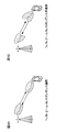
- FIG. 2A is a diagram illustrating an example of a single BF
- FIG. 2B is a diagram illustrating an example of a multiple BF
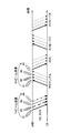
- FIG. 3A is a diagram illustrating an example of a single BF
- FIGS. 3B and 3C are diagrams illustrating an example of a multiple BF.
- FIG. 4A illustrates a case where Tx / Rx beam correspondence can be used
- FIG. 4B illustrates a case where Tx / Rx beam correspondence cannot be used.
- M2M may be referred to as D2D (Device To Device), V2V (Vehicle To Vehicle), or the like depending on a device to communicate. Designing a new communication access method (New RAT (Radio Access Technology)) is being studied in order to satisfy the above-mentioned various communication requirements.
- New RAT Radio Access Technology
- a beam (antenna directivity) can be formed by controlling the amplitude and / or phase of a signal transmitted / received from each element. This processing is also called beam forming (BF) and can reduce radio wave propagation loss.
- BF beam forming
- Random access procedures are also referred to as collision-type random access (CBRA: Contention-Based Random Access, etc.) and non-collision-type random access (Non-CBRA, contention-free random access (CFRA), etc. )
- CBRA collision-type random access
- Non-CBRA contention-free random access
- CBRA collision type random access
- a user terminal selects a preamble randomly selected from a plurality of preambles (also referred to as a random access preamble, a random access channel (PRACH), a RACH preamble, etc.) defined in each cell.
- Collision-type random access is a random access procedure led by a user terminal, and can be used, for example, at the time of initial access or at the start or restart of UL transmission.
- Non-collision type random access (Non-CBRA, CFRA: Contention-Free Random Access)
- the radio base station uses a downlink (DL) control channel (PDCCH: Physical Downlink Control Channel, EPDCCH: Enhanced PDCCH, etc.) as a preamble. Is uniquely assigned to the user terminal, and the user terminal transmits the preamble assigned by the radio base station.
- Non-collision type random access is a network-initiated random access procedure, and can be used, for example, at the time of handover, when DL transmission is started or restarted (when transmission of DL retransmission instruction information is started or restarted in UL), etc. .
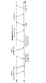
- FIG. 1 is a diagram showing an example of collision-type random access.
- a user terminal uses a random access channel (for example, MIB (Mater Information Block) and / or SIB (System Information Block)) or higher layer signaling (for example, RRC (Radio Resource Control) signaling).
- Information PRACH configuration information
- PRACH configuration indicating a PRACH configuration (PRACH configuration, RACH configuration) is received in advance.
- the PRACH configuration information includes, for example, a plurality of preambles (for example, preamble format) defined for each cell, time resources (for example, system frame number, subframe number) used for PRACH transmission, and frequency resources (for example, 6 resource blocks) (PRB: offset (prach-FrequencyOffset) indicating the start position of Physical Resource Block) can be indicated.
- preamble format for example, preamble format
- time resources for example, system frame number, subframe number
- frequency resources for example, 6 resource blocks
- PRB offset (prach-FrequencyOffset) indicating the start position of Physical Resource Block
- the radio base station When the radio base station detects the preamble, it transmits a random access response (RAR: Random Access Response) as a response (message 2).
- RAR Random Access Response
- the user terminal fails to receive the RAR within a predetermined period (RAR window) after transmitting the preamble, the user terminal increases the transmission power of the PRACH and transmits (retransmits) the preamble again. Note that increasing the transmission power during retransmission is also called power ramping.
- the user terminal that has received the RAR adjusts the UL transmission timing based on the timing advance (TA) included in the RAR, and establishes UL synchronization.
- the user terminal transmits a control message of a higher layer (L2 / L3: Layer 2 / Layer 3) using a UL resource specified by the UL grant included in the RAR (message 3).
- the control message includes a user terminal identifier (UE-ID).
- the identifier of the user terminal may be, for example, C-RNTI (Cell-Radio Network Temporary Identifier) in the RRC connection state, or S-TMSI (System Architecture Evolution-Temporary Mobile in the idle state). It may be a higher-layer UE-ID such as (Subscriber Identity).
- the radio base station transmits a contention resolution message in response to the control message of the upper layer (message 4).
- the collision resolution message is transmitted based on the user terminal identifier included in the control message.
- the user terminal that has successfully detected the collision resolution message transmits an acknowledgment (ACK: Acknowledge) in HARQ (Hybrid Automatic Repeat reQuest) to the radio base station. Thereby, the user terminal in an idle state transits to the RRC connection state.
- ACK Acknowledge
- HARQ Hybrid Automatic Repeat reQuest
- the user terminal that failed to detect the collision resolution message determines that a collision has occurred, reselects the preamble, and repeats the random access procedure of messages 1 to 4.
- the radio base station detects that the collision has been resolved by the ACK from the user terminal, the radio base station transmits a UL grant to the user terminal.
- the user terminal transmits UL data using the UL resource allocated by the UL grant.
- the random access procedure can be started autonomously.
- UL data is transmitted using UL resources allocated to the user terminal by the UL grant after UL synchronization is established, highly reliable UL transmission is possible.
- future wireless communication systems for example, 5G, NR
- 5G Fifth Generation
- NR New Radio
- future wireless communication systems are expected to realize various wireless communication services to satisfy different requirements (for example, ultra-high speed, large capacity, ultra-low delay, etc.).
- requirements for example, ultra-high speed, large capacity, ultra-low delay, etc.
- BF beam forming
- Digital BF can be classified into digital BF and analog BF.
- Digital BF is a method of performing precoding signal processing (for a digital signal) on baseband.
- parallel processing of inverse fast Fourier transform (IFFT: Inverse Fast Fourier Transform) / digital-analog conversion (DAC: Digital to Analog Converter) / RF (Radio Frequency) is required for the number of antenna ports (RF chains). Become. On the other hand, as many beams as the number of RF chains can be formed at an arbitrary timing.
- Analog BF is a method using a phase shifter on RF. In this case, since only the phase of the RF signal is rotated, the configuration is easy and can be realized at low cost, but a plurality of beams cannot be formed at the same timing. Specifically, in analog BF, only one beam can be formed at a time for each phase shifter.
- a base station for example, called eNB (evolved Node B), BS (Base Station), etc.
- eNB evolved Node B
- BS Base Station
- one beam can be formed at a certain time. Therefore, when transmitting a plurality of beams using only analog BF, it is necessary to switch or rotate the beams in time because they cannot be transmitted simultaneously with the same resource.
- a hybrid BF configuration in which a digital BF and an analog BF are combined can also be used.
- future wireless communication systems for example, 5G
- introduction of large-scale MIMO is being studied.
- the circuit configuration becomes expensive. For this reason, it is assumed that a hybrid BF configuration is used in 5G.
- BF operation includes single BF operation using one BF (Single BF operation) and multiple BF operation using multiple BFs (see FIGS. 2 and 3).
- Single BF operation orthogonal preambles are applied so that UL beams (directivity) are orthogonal (a collision is avoided) between a plurality of user terminals (see FIG. 2A). For this reason, as shown in FIG. 3A, the same resource can be used in the frequency domain-time domain.
- BF is applied so that UL beams (directivity) are orthogonal (avoid collision) between a plurality of user terminals.
- the multiple BF operation it may be possible to select an optimal Rx beam by transmitting a plurality of times while applying different beam patterns in the time direction (beam scanning) (see FIG. 2B).
- FIG. 3B shows an example of multiple BF operation in a radio base station (also referred to as gNB). In this case, the radio base station receives signals from the user terminal using different Rx beams in a plurality of unit time intervals.
- FIG. 3C shows an example of multiple BF operations in the radio base station and the user terminal.
- the radio base station receives signals from the user terminal using different Rx beams in a plurality of unit time intervals.
- the user terminal transmits a signal using specific Tx beams (UE beam # 1 and UE beam # 2 in FIG. 3C).
- the number of orthogonal preambles can be reduced compared to single BF operation.
- different beam patterns are applied in the time direction, so that more PRACH (Physical Random Access Channel) resources are required in the time domain.
- the transmission method using the beam may be appropriately controlled.
- Tx / Rx reciprocity can be used (supported).
- Tx / Rx reciprocity cannot be used (not supported) (see FIG. 4).
- the matching of the beam applied to transmission and the beam applied to reception is not limited to a complete match, and includes a case where they match within a predetermined allowable range.
- the Tx / Rx reciprocity may be referred to as Tx / Rx beam correspondence, Tx / Rx correspondence, and beam correspondence.
- Tx / Rx beam correspondence is applied (see FIG. 4A)
- beam information detected by the DL signal is used for beam forming for PRACH, RAR, message 3, and message 4.
- Tx / Rx reciprocity is used, the DLTx beam and the ULRx beam are linked.
- the radio base station transmits a synchronization signal and a broadcast channel signal to the user terminals using Tx beams of beam indexes # 1 to # 4 by analog BF.
- the user terminal detects the best BSTx beam from the received DL signal (Tx beam scanning). Thereby, the best beam index of the BSTx beam is obtained.
- Tx beam scanning Tx beam scanning
- the user terminal performs PRACH transmission using the PRACH resource corresponding to the beam index # 1 of the obtained BSTx / Rx beam.
- the radio base station can detect PRACH with a suitable received beam (beam index # 1) and obtain a corresponding BSTx / Rx beam index # 1 (Rx beam scanning). ).
- the radio base station and the user terminal perform transmission / reception using an optimum beam in a random access procedure after RAR transmission.
- Information regarding which PRACH resource is associated with a radio resource such as a beam index of which BSTx / Rx beam or time and / or frequency corresponding to each BSTx / Rx beam may be determined in advance by the specification. It is also possible to notify the user terminal from the radio base station by broadcast information, higher layer signaling, downlink control signal, or the like.
- PRACH retransmission control is defined in the random access procedure of the existing LTE system.
- the user terminal attempts to receive the message 2 (RAR) for a predetermined interval after transmitting the random access preamble. If reception of message 2 fails, message 1 is transmitted (retransmitted) again by increasing the transmission power of PRACH. Note that increasing the transmission power during signal retransmission is also referred to as power ramping.
- one aspect of the present invention is a transmission that transmits a PRACH using a receiving unit that receives a DL signal transmitted from a radio base station, and a predetermined random access preamble (PRACH) resource selected based on the DL signal. And a control unit that controls retransmission of PRACH using a PRACH resource different from the predetermined PRACH resource when reception of a response signal to the PRACH transmission is not successful in the radio base station. , Retransmitting the PRACH.
- PRACH random access preamble
- a plurality of beams (beam patterns) are different means, for example, a case where at least one of the following (1) to (6) applied to a plurality of beams is different: However, it is not limited to this.
- precoding weights may be different, and precoding schemes (for example, linear precoding and non-linear precoding) may be different.
- precoding schemes for example, linear precoding and non-linear precoding
- linear precoding follow zero-forcing (ZF) norm, normalized zero-forcing (R-ZF) norm, minimum mean square error (MMSE) norm, etc.
- Precoding is mentioned.
- non-linear precoding include precoding such as Dirty Paper Coding (DPC), Vector Perturbation (VP), and THP (Tomlinson Harashima Precoding). Note that applied precoding is not limited to these.
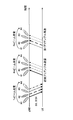
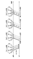
- FIG. 6 is a diagram illustrating an example of PRACH retransmission control.
- FIG. 6 shows a case where four beam indexes (# 1 to # 4) are applied, but the number of beam indexes is not limited to this.
- the radio base station transmits a synchronization signal and a broadcast channel signal to the user terminal by using Tx beams of beam indexes # 1 to # 4 by analog BF.
- the user terminal detects the best BSTx beam from the received DL signal (Tx beam scanning). Thereby, the best beam index of the BSTx beam is obtained.
- Tx beam scanning Tx beam scanning
- the user terminal performs PRACH transmission using the PRACH resource corresponding to the obtained beam index # 1 of the BSTx / Rx beam (initial preamble transmission).
- the radio base station can detect PRACH with a suitable received beam (beam index # 1) and obtain a corresponding BSTx / Rx beam index # 1 (Rx beam scanning). ).
- the radio base station may not receive the initial preamble transmitted from the user terminal.
- the radio base station cannot transmit a random access response (RAR). That is, the user terminal cannot receive a response signal for PRACH transmission.
- RAR random access response
- the user terminal retransmits the random access preamble on the assumption that the initial preamble transmission has failed.
- the user terminal can control retransmission of the PRACH using a PRACH resource different from the predetermined PRACH resource used in the initial preamble transmission.
- the user terminal As a method for determining that the user terminal has not succeeded (failed) in transmitting the random access preamble, there is presence / absence of RAR reception in a predetermined period. For example, when the user terminal fails to receive the RAR within a predetermined period set after transmitting the random access preamble, the user terminal performs retransmission assuming that transmission of the random access preamble has failed.
- the PRACH is retransmitted using another PRACH resource different from the PRACH resource corresponding to the Tx / Rx beam index (beam index # 1) used in the initial preamble transmission.
- Other PRACH resources may be PRACH resources corresponding to Tx / Rx beam indexes (beam index # 2 in FIG. 6) different from beam index # 1.
- power ramping may be applied, or may be switched to another PRACH resource without being applied.
- the user terminal can quickly switch to a PRACH resource corresponding to another beam index and transmit a random access preamble. It can be performed. In this way, the success probability of random access preamble reception can be increased in the radio base station.
- initial preamble transmission is performed a plurality of times using the same Tx / Rx beam index. Then, when it is determined that the initial preamble cannot be received in the radio base station (for example, the user terminal cannot receive the RAR), the Tx / Rx beam index (beam index # 1) used in the initial preamble transmission is set.
- the PRACH is retransmitted using another PRACH resource different from the corresponding PRACH resource.
- Other PRACH resources may be PRACH resources corresponding to Tx / Rx beam indexes (beam index # 2 in FIG. 6) different from beam index # 1. That is, when retransmission using a predetermined PRACH resource fails a predetermined number of times, retransmission control is performed using a different PRACH resource.
- power ramping may be applied.
- initial preamble transmission is performed a plurality of times by gradually increasing transmission power using PRACH resources corresponding to the same Tx / Rx beam index.
- retransmission control is performed using a different PRACH resource.
- power control when power ramping is applied may use the same method as the existing LTE system, or may apply a different method.
- the width of the electric power increased by one ramping may be increased as compared with the existing LTE system.
- by setting a small number of retransmissions using PRACH resources corresponding to the same Tx / Rx beam index it is possible to quickly switch to PRACH resources corresponding to different beam indexes.
- the success probability of PRACH transmission is improved by repeatedly retransmitting the same preamble, and an inappropriate beam index is supported. Even when the PRACH resource is selected, the random access preamble can be transmitted by switching to the PRACH resource corresponding to another beam index.
- the power increased by the power ramping in the initial preamble transmission is retransmitted in the PRACH retransmission. It may be used as it is. Alternatively, power may be initialized when retransmission is performed using different PRACH resources.
- the user terminal performs radio link failure. You may judge. In this case, control is performed so as to attempt reconnection between the radio base station and the user terminal at different frequencies in the system.
- the PRACH resource to be used may be determined in advance, and the radio base station broadcasts it. You may do it.
- the PRACH resource corresponding to the beam index that is incremented (increased) by 1 to the beam index of the beam for which PRACH transmission has failed may be determined in advance so as to be used for the next retransmission, or corresponds to the beam index used for the retransmission.
- the radio base station may report the order of the PRACH resources.
- the network side may notify a plurality of beam indexes and the order of using PRACH resources corresponding to the beam indexes on the control channel.
- FIG. 7 is a diagram illustrating an example of PRACH retransmission control.
- the radio base station transmits a synchronization signal and a broadcast channel signal to the user terminal by using Tx beams of beam indexes # 1 to # 4 by analog BF.
- the user terminal detects the best BSTx beam from the received DL signal (Tx beam scanning). Thereby, the best beam index of the BSTx beam is obtained.
- Tx beam scanning Tx beam scanning
- the user terminal performs PRACH transmission using the PRACH resource corresponding to the obtained beam index # 1 of the BSTx / Rx beam (initial preamble transmission).
- the radio base station can detect PRACH with a suitable received beam (beam index # 1) and obtain a corresponding BSTx / Rx beam index # 1 (Rx beam scanning). ).
- the radio base station may not receive the initial preamble transmitted from the user terminal. In this case, the radio base station cannot transmit a random access response (RAR). That is, the user terminal cannot receive a response signal for PRACH transmission.
- RAR random access response
- the PRACH retransmission is controlled using a PRACH resource different from the predetermined PRACH resource used in the initial preamble transmission.
- PRACH is transmitted a plurality or repeatedly.
- PRACH transmission is performed using a PRACH resource with beam index # 1
- PRACH transmission is performed using a PRACH resource with beam index # 2.
- PRACH transmission is performed using the PRACH resource with beam index # 2 (first preamble retransmission).
- the former can be preferably applied when digital BF is used, and the latter can be preferably applied when analog BF is used.
- PRACH transmission is performed using the PRACH resource with the beam index # 1, and the PRACH resource with the beam index # 2 and the PRACH resource with the beam index # 3 are used.
- PRACH is transmitted.
- PRACH transmission is performed using the PRACH resource of beam index # 1
- PRACH transmission is performed using the PRACH resource of beam index # 2
- PRACH transmission is performed using the PRACH resource of beam index # 3 (second preamble). resend).
- the former can be preferably applied when digital BF is used, and the latter can be preferably applied when analog BF is used.
- initial preamble transmission is performed a plurality of times by gradually increasing the transmission power using PRACH resources corresponding to the same Tx / Rx beam index. Then, when it is determined that the radio base station cannot receive the initial preamble, a Tx / Rx beam index (in FIG. 7) different from the Tx / Rx beam index (beam index # 1) used in the initial preamble transmission.
- the PRACH is retransmitted using the PRACH resource corresponding to the beam index # 2). That is, when retransmission using a predetermined PRACH resource has failed a predetermined number of times, retransmission control is performed by adding a different PRACH resource.
- the success probability of PRACH transmission is improved by repeatedly retransmitting the same preamble, and when a PRACH resource corresponding to an inappropriate beam index is selected. Even if it exists, the preamble transmission using the PRACH resource corresponding to the other added beam index can be performed.
- PRACH resources that are continuous in time may be selected at the time of retransmission. By doing so, it is possible to coherently combine consecutive PRACHs at the radio base station and improve the reception probability of PRACH transmission. On the other hand, coherent synthesis cannot be applied when there is an influence of phase noise at a high frequency. Therefore, in such a case, PRACH resources that are not continuous in time may be selected at the time of retransmission so that the reception probability can be increased by the selection diversity effect.
- power control when power ramping is applied may use the same method as the existing LTE system, or may apply a different method.
- power ramping even if all prepared beams (# 1 to # 4 in FIG. 7) are added and PRACH transmission / retransmission is performed, the radio base station cannot receive the initial preamble. The power ramping may be sometimes performed.
- the power ramping during the initial preamble transmission is large.
- the obtained power may be used for PRACH retransmission as it is, or the power may be initialized when PRACH is retransmitted.
- the user terminal determines that radio link failure has occurred. Also good. In this case, control is performed so as to attempt reconnection between the radio base station and the user terminal at different frequencies in the system.
- the PRACH resource to be used may be determined in advance. You may notify. For example, the PRACH resource with the beam index incremented (increased) by 1 to the beam index of the failed beam may be determined in advance to be added to the next retransmission, or the order of the PRACH resources corresponding to the beam index used for the retransmission. May be broadcast by the radio base station.
- the network side may notify a plurality of beam indexes and the order of using PRACH resources corresponding to the beam indexes on the control channel.
- the user terminal when retransmitting the PRACH, the user terminal re-detects the best BSTx beam from the downlink signal transmitted by the BSTx beam, and then performs the PRACH retransmission according to the present invention. Also good. By redetecting the best BSTx beam in this way, the PRACH can be received more efficiently on the radio base station side.
- the PRACH may be transmitted using the power calculated based on the number of repetitions actually used. Even in this case, when power ramping is applied, power ramping is performed as described above.
- PRACH transmission when processing for repeatedly transmitting PRACH a plurality of times is performed, PRACH transmission may be performed by changing the beam index after a predetermined number of repetitions.
- frequency hopping is applied to the PRACH signal, the beam index may be changed every time frequency hopping is performed.
- wireless communication system Wireless communication system
- communication is performed using any one or a combination of the wireless communication methods according to the above embodiments of the present invention.
- FIG. 8 is a diagram illustrating an example of a schematic configuration of a wireless communication system according to an embodiment of the present invention.
- carrier aggregation (CA) and / or dual connectivity (DC) in which a plurality of basic frequency blocks (component carriers) each having a system bandwidth (for example, 20 MHz) of the LTE system as one unit are applied. can do.
- DC dual connectivity
- the wireless communication system 1 includes LTE (Long Term Evolution), LTE-A (LTE-Advanced), LTE-B (LTE-Beyond), SUPER 3G, IMT-Advanced 4G (4th generation mobile communication system), 5G. (5th generation mobile communication system), FRA (Future Radio Access), New-RAT (Radio Access Technology), etc., or a system that realizes these.
- LTE Long Term Evolution
- LTE-A Long Term Evolution-Advanced
- LTE-B LTE-Beyond
- SUPER 3G IMT-Advanced 4G (4th generation mobile communication system)
- 5G. 5th generation mobile communication system
- FRA Full Radio Access
- New-RAT Radio Access Technology
- a radio base station using a plurality of beamforming communicates with a user terminal, and the user terminal transmits a random access preamble (PRACH) including beam information related to the beam of the radio base station. Then, the radio base station receives the PRACH including the beam information.
- PRACH random access preamble
- the radio communication system 1 includes a radio base station 11 that forms a macro cell C1 having a relatively wide coverage, and a radio base station 12 (12a-12c) that is arranged in the macro cell C1 and forms a small cell C2 that is narrower than the macro cell C1. It is equipped with. Moreover, the user terminal 20 is arrange
- the user terminal 20 can be connected to both the radio base station 11 and the radio base station 12. It is assumed that the user terminal 20 uses the macro cell C1 and the small cell C2 simultaneously by CA or DC. Moreover, the user terminal 20 may apply CA or DC using a plurality of cells (CC) (for example, 5 or less CCs, 6 or more CCs).
- CC cells
- Communication between the user terminal 20 and the radio base station 11 can be performed using a carrier having a relatively low frequency band (for example, 2 GHz) and a narrow bandwidth (referred to as an existing carrier or a legacy carrier).
- a carrier having a relatively high frequency band for example, 3.5 GHz, 5 GHz, etc.
- the same carrier may be used.
- the configuration of the frequency band used by each radio base station is not limited to this.
- a wired connection for example, an optical fiber compliant with CPRI (Common Public Radio Interface), an X2 interface, etc.
- a wireless connection It can be set as the structure to do.
- the radio base station 11 and each radio base station 12 are connected to the higher station apparatus 30 and connected to the core network 40 via the higher station apparatus 30.
- the upper station device 30 includes, for example, an access gateway device, a radio network controller (RNC), a mobility management entity (MME), and the like, but is not limited thereto.
- RNC radio network controller
- MME mobility management entity
- Each radio base station 12 may be connected to the higher station apparatus 30 via the radio base station 11.
- the radio base station 11 is a radio base station having a relatively wide coverage, and may be called a macro base station, an aggregation node, an eNB (eNodeB), a transmission / reception point, or the like.
- the radio base station 12 is a radio base station having local coverage, and includes a small base station, a micro base station, a pico base station, a femto base station, a HeNB (Home eNodeB), an RRH (Remote Radio Head), and transmission / reception. It may be called a point or the like.
- a radio base station 10 when the radio base station 11 and the radio base station 12 are not distinguished, they are collectively referred to as a radio base station 10.
- Each user terminal 20 is a terminal that supports various communication schemes such as LTE and LTE-A, and may include not only a mobile communication terminal (mobile station) but also a fixed communication terminal (fixed station).
- orthogonal frequency division multiple access (OFDMA) is applied to the downlink, and single carrier-frequency division multiple access (SC-FDMA) is used for the uplink.
- SC-FDMA single carrier-frequency division multiple access
- OFDMA is a multi-carrier transmission scheme that performs communication by dividing a frequency band into a plurality of narrow frequency bands (subcarriers) and mapping data to each subcarrier.
- SC-FDMA is a single-carrier transmission scheme that reduces interference between terminals by dividing the system bandwidth into bands consisting of one or continuous resource blocks for each terminal and using a plurality of terminals with mutually different bands. is there.
- the uplink and downlink radio access schemes are not limited to these combinations, and other radio access schemes may be used.
- a downlink shared channel there are a downlink shared channel (PDSCH) shared by each user terminal 20, a broadcast channel (PBCH: Physical Broadcast Channel), a downlink L1 / L2 control channel, and the like. Used. User data, upper layer control information, SIB (System Information Block), etc. are transmitted by PDSCH. Also, MIB (Master Information Block) is transmitted by PBCH.
- PBCH Physical Broadcast Channel
- SIB System Information Block
- MIB Master Information Block
- Downlink L1 / L2 control channels include PDCCH (Physical Downlink Control Channel), EPDCCH (Enhanced Physical Downlink Control Channel), PCFICH (Physical Control Format Indicator Channel), PHICH (Physical Hybrid-ARQ Indicator Channel), and the like.
- Downlink control information (DCI: Downlink Control Information) including PDSCH and PUSCH scheduling information is transmitted by the PDCCH.
- the number of OFDM symbols used for PDCCH is transmitted by PCFICH.
- the PHICH transmits HARQ (Hybrid Automatic Repeat reQuest) delivery confirmation information (for example, retransmission control information, HARQ-ACK, ACK / NACK, etc.) to the PUSCH.
- HARQ Hybrid Automatic Repeat reQuest
- EPDCCH is frequency-division multiplexed with PDSCH (downlink shared data channel), and is used for transmission of DCI and the like in the same manner as PDCCH.
- an uplink shared channel (PUSCH) shared by each user terminal 20, an uplink control channel (PUCCH: Physical Uplink Control Channel), a random access channel (PRACH: Physical Random Access Channel) is used.
- PUSCH uplink shared channel
- PUCCH Physical Uplink Control Channel
- PRACH Physical Random Access Channel
- User data and higher layer control information are transmitted by PUSCH.
- downlink radio quality information CQI: Channel Quality Indicator
- delivery confirmation information and the like are transmitted by PUCCH.
- a random access preamble for establishing connection with a cell is transmitted by the PRACH.
- a cell-specific reference signal CRS
- CSI-RS channel state information reference signal
- DMRS demodulation reference signal
- PRS Positioning Reference Signal
- a measurement reference signal SRS: Sounding Reference Signal
- a demodulation reference signal DMRS
- the DMRS may be referred to as a user terminal specific reference signal (UE-specific Reference Signal). Further, the transmitted reference signal is not limited to these.
- FIG. 9 is a diagram illustrating an example of the overall configuration of a radio base station according to an embodiment of the present invention.
- the radio base station 10 includes a plurality of transmission / reception antennas 101, an amplifier unit 102, a transmission / reception unit 103, a baseband signal processing unit 104, a call processing unit 105, and a transmission path interface 106.
- the transmission / reception antenna 101, the amplifier unit 102, and the transmission / reception unit 103 may each be configured to include one or more.
- User data transmitted from the radio base station 10 to the user terminal 20 via the downlink is input from the higher station apparatus 30 to the baseband signal processing unit 104 via the transmission path interface 106.
- PDCP Packet Data Convergence Protocol
- RLC Radio Link Control
- MAC Medium Access
- Retransmission control for example, HARQ transmission processing
- scheduling transmission format selection, channel coding, inverse fast Fourier transform (IFFT) processing, precoding processing, and other transmission processing
- IFFT inverse fast Fourier transform
- precoding processing precoding processing
- other transmission processing are performed and the transmission / reception unit 103.
- the downlink control signal is also subjected to transmission processing such as channel coding and inverse fast Fourier transform, and is transferred to the transmission / reception unit 103.
- the transmission / reception unit 103 converts the baseband signal output by precoding for each antenna from the baseband signal processing unit 104 to a radio frequency band and transmits the converted signal.
- the radio frequency signal frequency-converted by the transmission / reception unit 103 is amplified by the amplifier unit 102 and transmitted from the transmission / reception antenna 101.
- the transmission / reception unit 103 can be configured by a transmitter / receiver, a transmission / reception circuit, or a transmission / reception device which is described based on common recognition in the technical field according to the present invention.
- the transmission / reception part 103 may be comprised as an integral transmission / reception part, and may be comprised from a transmission part and a receiving part.
- the radio frequency signal received by the transmission / reception antenna 101 is amplified by the amplifier unit 102.
- the transmission / reception unit 103 receives the uplink signal amplified by the amplifier unit 102.
- the transmission / reception unit 103 converts the frequency of the received signal into a baseband signal and outputs it to the baseband signal processing unit 104.
- the baseband signal processing unit 104 performs Fast Fourier Transform (FFT) processing, Inverse Discrete Fourier Transform (IDFT) processing, and error correction on user data included in the input upstream signal. Decoding, MAC retransmission control reception processing, RLC layer and PDCP layer reception processing are performed and transferred to the upper station apparatus 30 via the transmission path interface 106.
- the call processing unit 105 performs call processing such as communication channel setting and release, status management of the radio base station 10, and radio resource management.
- the transmission path interface 106 transmits and receives signals to and from the higher station apparatus 30 via a predetermined interface.
- the transmission path interface 106 transmits / receives signals (backhaul signaling) to / from other radio base stations 10 via an interface between base stations (for example, an optical fiber compliant with CPRI (Common Public Radio Interface), X2 interface). May be.
- CPRI Common Public Radio Interface
- X2 interface May be.
- the transmission / reception unit 103 may further include an analog beam forming unit that performs analog beam forming.
- the analog beam forming unit includes an analog beam forming circuit (for example, phase shifter, phase shift circuit) or an analog beam forming apparatus (for example, phase shifter) described based on common recognition in the technical field according to the present invention. can do.
- the transmission / reception antenna 101 can be configured by an array antenna, for example.
- the transmission / reception unit 103 is configured to be able to apply single BF and multi-BF.
- the transceiver 103 may transmit a synchronization signal, a broadcast channel signal, and a reference signal for beam pattern measurement for beam measurement at the user terminal. Further, the transmission / reception unit 103 receives a random access preamble (PRACH) including beam information related to the DL signal beam. Moreover, the transmission / reception part 103 receives PRACH which the user terminal transmitted using the optimal beam information (for example, beam index).
- PRACH random access preamble
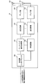
- FIG. 10 is a diagram illustrating an example of a functional configuration of the radio base station according to the embodiment of the present invention.
- the functional block of the characteristic part in this embodiment is mainly shown, and the wireless base station 10 shall also have another functional block required for radio
- the baseband signal processing unit 104 includes at least a control unit (scheduler) 301, a transmission signal generation unit 302, a mapping unit 303, a reception signal processing unit 304, and a measurement unit 305. These configurations may be included in the radio base station 10, and a part or all of the configurations may not be included in the baseband signal processing unit 104.
- the control unit (scheduler) 301 controls the entire radio base station 10.
- the control part 301 can be comprised from the controller, the control circuit, or control apparatus demonstrated based on the common recognition in the technical field which concerns on this invention.
- the control unit 301 controls signal generation by the transmission signal generation unit 302 and signal allocation by the mapping unit 303, for example.
- the control unit 301 also controls signal reception processing by the reception signal processing unit 304 and signal measurement by the measurement unit 305.
- the control unit 301 controls scheduling (for example, resource allocation) of system information, a downlink data signal transmitted on the PDSCH, and a downlink control signal transmitted on the PDCCH and / or EPDCCH. Further, the control unit 301 controls generation of a downlink control signal (for example, delivery confirmation information) and a downlink data signal based on a result of determining whether or not retransmission control is necessary for the uplink data signal.
- the control unit 301 also controls scheduling of synchronization signals (for example, PSS (Primary Synchronization Signal) / SSS (Secondary Synchronization Signal)) and downlink reference signals such as CRS, CSI-RS, and DMRS.
- control unit 301 includes an uplink data signal transmitted on the PUSCH, an uplink control signal transmitted on the PUCCH and / or PUSCH (for example, delivery confirmation information), an RACH preamble transmitted on the PRACH, an uplink reference signal, and the like. Control scheduling.
- the control unit 301 uses the digital BF (for example, precoding) by the baseband signal processing unit 104 and / or the analog BF (for example, phase rotation) by the transmission / reception unit 103 to form a Tx beam and / or an Rx beam. To control.
- the control unit 301 detects the PRACH transmitted from the user terminal a plurality of times while performing BSRx beam scanning. Thereby, the best BSRx beam can be measured.
- the transmission signal generation unit 302 generates a downlink signal (downlink control signal, downlink data signal, downlink reference signal, etc.) based on an instruction from the control unit 301, and outputs it to the mapping unit 303.
- the transmission signal generation unit 302 can be configured by a signal generator, a signal generation circuit, or a signal generation device described based on common recognition in the technical field according to the present invention.
- the transmission signal generation unit 302 generates, for example, a DL assignment that notifies downlink signal allocation information and a UL grant that notifies uplink signal allocation information based on an instruction from the control unit 301. Further, the downlink data signal is subjected to coding processing and modulation processing according to a coding rate, a modulation scheme, and the like determined based on channel state information (CSI: Channel State Information) from each user terminal 20.
- CSI Channel State Information
- the mapping unit 303 maps the downlink signal generated by the transmission signal generation unit 302 to a predetermined radio resource based on an instruction from the control unit 301, and outputs it to the transmission / reception unit 103.
- the mapping unit 303 can be configured by a mapper, a mapping circuit, or a mapping device described based on common recognition in the technical field according to the present invention.
- the reception signal processing unit 304 performs reception processing (for example, demapping, demodulation, decoding, etc.) on the reception signal input from the transmission / reception unit 103.
- the received signal is, for example, an uplink signal (uplink control signal, uplink data signal, uplink reference signal, etc.) transmitted from the user terminal 20.
- the reception signal processing unit 304 can be configured by a signal processor, a signal processing circuit, or a signal processing device described based on common recognition in the technical field according to the present invention.
- the reception signal processing unit 304 outputs the information decoded by the reception processing to the control unit 301. For example, when receiving PUCCH including HARQ-ACK, HARQ-ACK is output to control section 301.
- the reception signal processing unit 304 outputs the reception signal and the signal after reception processing to the measurement unit 305.
- the measurement unit 305 performs measurement on the received signal.
- the measurement part 305 can be comprised from the measuring device, measurement circuit, or measurement apparatus demonstrated based on common recognition in the technical field which concerns on this invention.
- the measurement unit 305 may, for example, receive power (for example, RSRP (Reference Signal Received Power)), reception quality (for example, RSRQ (Reference Signal Received Quality), SINR (Signal to Interference plus Noise Ratio)) or channel of the received signal. You may measure about a state etc.
- the measurement result may be output to the control unit 301.
- the user terminal When the user terminal receives the DL signal transmitted from the radio base station, transmits the PRACH using a predetermined PRACH resource selected based on the DL signal, and the response signal for the PRACH transmission is not successfully received, PRACH retransmission is controlled using a PRACH resource different from a predetermined PRACH resource.
- FIG. 11 is a diagram illustrating an example of the overall configuration of a user terminal according to an embodiment of the present invention.
- the user terminal 20 includes a plurality of transmission / reception antennas 201, an amplifier unit 202, a transmission / reception unit 203, a baseband signal processing unit 204, and an application unit 205.
- the transmission / reception antenna 201, the amplifier unit 202, and the transmission / reception unit 203 may each be configured to include one or more.
- the radio frequency signal received by the transmission / reception antenna 201 is amplified by the amplifier unit 202.
- the transmission / reception unit 203 receives the downlink signal amplified by the amplifier unit 202.
- the transmission / reception unit 203 converts the frequency of the received signal into a baseband signal and outputs it to the baseband signal processing unit 204.
- the transmission / reception unit 203 can be configured by a transmitter / receiver, a transmission / reception circuit, or a transmission / reception device described based on common recognition in the technical field according to the present invention.
- the transmission / reception unit 203 may be configured as an integral transmission / reception unit, or may be configured from a transmission unit and a reception unit.
- the baseband signal processing unit 204 performs FFT processing, error correction decoding, retransmission control reception processing, and the like on the input baseband signal.
- the downlink user data is transferred to the application unit 205.
- the application unit 205 performs processing related to layers higher than the physical layer and the MAC layer.
- broadcast information in the downlink data is also transferred to the application unit 205.
- uplink user data is input from the application unit 205 to the baseband signal processing unit 204.
- the baseband signal processing unit 204 performs transmission / reception by performing retransmission control transmission processing (for example, HARQ transmission processing), channel coding, precoding, discrete Fourier transform (DFT) processing, IFFT processing, and the like. Is transferred to the unit 203.
- the transmission / reception unit 203 converts the baseband signal output from the baseband signal processing unit 204 into a radio frequency band and transmits it.
- the radio frequency signal frequency-converted by the transmission / reception unit 203 is amplified by the amplifier unit 202 and transmitted from the transmission / reception antenna 201.
- the transmission / reception unit 203 may further include an analog beam forming unit that performs analog beam forming.
- the analog beam forming unit includes an analog beam forming circuit (for example, phase shifter, phase shift circuit) or an analog beam forming apparatus (for example, phase shifter) described based on common recognition in the technical field according to the present invention. can do.
- the transmission / reception antenna 201 can be configured by, for example, an array antenna.
- the transmission / reception unit 203 is configured to be able to apply single BF and multi-BF.
- the transmission / reception unit 203 may receive a synchronization signal, a broadcast channel signal, and a reference signal for beam pattern measurement for beam measurement. Further, the transmission / reception unit 203 transmits a random access preamble (PRACH) including beam information related to the beam detected from the DL signal. At this time, the transmission / reception unit 203 transmits the PRACH using optimal beam information (for example, a beam index).
- PRACH random access preamble
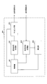
- FIG. 12 is a diagram illustrating an example of a functional configuration of a user terminal according to an embodiment of the present invention.
- the functional blocks of the characteristic part in the present embodiment are mainly shown, and the user terminal 20 also has other functional blocks necessary for wireless communication.
- the baseband signal processing unit 204 included in the user terminal 20 includes at least a control unit 401, a transmission signal generation unit 402, a mapping unit 403, a reception signal processing unit 404, and a measurement unit 405. Note that these configurations may be included in the user terminal 20, and some or all of the configurations may not be included in the baseband signal processing unit 204.
- the control unit 401 controls the entire user terminal 20.
- the control unit 401 can be composed of a controller, a control circuit, or a control device described based on common recognition in the technical field according to the present invention.
- the control unit 401 controls, for example, signal generation by the transmission signal generation unit 402 and signal allocation by the mapping unit 403.
- the control unit 401 controls signal reception processing by the reception signal processing unit 404 and signal measurement by the measurement unit 405.
- the control unit 401 obtains, from the received signal processing unit 404, a downlink control signal (a signal transmitted by PDCCH / EPDCCH) and a downlink data signal (a signal transmitted by PDSCH) transmitted from the radio base station 10.
- the control unit 401 controls generation of an uplink control signal (for example, delivery confirmation information) and an uplink data signal based on a downlink control signal, a result of determining whether or not retransmission control is required for the downlink data signal, and the like.
- the control unit 401 uses the digital BF (for example, precoding) by the baseband signal processing unit 204 and / or the analog BF (for example, phase rotation) by the transmission / reception unit 203 to form a transmission beam and / or a reception beam. To control.
- digital BF for example, precoding
- analog BF for example, phase rotation
- the control unit 401 detects the best BSTx beam from the received DL signal and performs control so as to obtain the best beam index of the BSTx beam. Further, in the first mode, the control unit 401 controls PRACH retransmission using a PRACH resource different from a predetermined PRACH resource (for example, a beam index). In addition, the control unit 401 performs retransmission control using a PRACH resource different from the predetermined PRACH resource when retransmission using the predetermined PRACH resource has failed a predetermined number of times.
- a predetermined PRACH resource for example, a beam index
- the control unit 401 when performing PRACH retransmission control after transmitting a PRACH using a predetermined PRACH resource, the control unit 401 adds a PRACH resource different from the predetermined PRACH resource according to the number of retransmissions. PRACH retransmission is performed. In addition, the control unit 401 applies power ramping in retransmission control using a predetermined PRACH resource. In this case, the control unit 401 controls PRACH retransmission using a predetermined PRACH resource (a PRACH resource for initial PRACH transmission) and a PRACH resource different from the predetermined PRACH resource.
- a predetermined PRACH resource a PRACH resource for initial PRACH transmission
- the transmission signal generation unit 402 generates an uplink signal (uplink control signal, uplink data signal, uplink reference signal, etc.) based on an instruction from the control unit 401 and outputs the uplink signal to the mapping unit 403.
- the transmission signal generation unit 402 can be configured by a signal generator, a signal generation circuit, or a signal generation device described based on common recognition in the technical field according to the present invention.
- the transmission signal generator 402 generates an uplink control signal related to delivery confirmation information and channel state information (CSI) based on an instruction from the controller 401, for example.
- the transmission signal generation unit 402 generates an uplink data signal based on an instruction from the control unit 401.
- the transmission signal generation unit 402 is instructed by the control unit 401 to generate an uplink data signal when the UL grant is included in the downlink control signal notified from the radio base station 10.
- the mapping unit 403 maps the uplink signal generated by the transmission signal generation unit 402 to a radio resource based on an instruction from the control unit 401, and outputs the radio signal to the transmission / reception unit 203.
- the mapping unit 403 can be configured by a mapper, a mapping circuit, or a mapping device described based on common recognition in the technical field according to the present invention.
- the reception signal processing unit 404 performs reception processing (for example, demapping, demodulation, decoding, etc.) on the reception signal input from the transmission / reception unit 203.
- the received signal is, for example, a downlink signal (downlink control signal, downlink data signal, downlink reference signal, etc.) transmitted from the radio base station 10.
- the reception signal processing unit 404 can be configured by a signal processor, a signal processing circuit, or a signal processing device described based on common recognition in the technical field according to the present invention. Further, the reception signal processing unit 404 can constitute a reception unit according to the present invention.
- the reception signal processing unit 404 outputs the information decoded by the reception processing to the control unit 401.
- the reception signal processing unit 404 outputs broadcast information, system information, RRC signaling, DCI, and the like to the control unit 401, for example.
- the reception signal processing unit 404 outputs the reception signal and the signal after reception processing to the measurement unit 405.
- the measurement unit 405 performs measurement on the received signal.
- the measurement unit 405 performs measurement using the beam forming RS transmitted from the radio base station 10.
- the measurement part 405 can be comprised from the measuring device, measurement circuit, or measurement apparatus demonstrated based on common recognition in the technical field which concerns on this invention.
- the measurement unit 405 may measure, for example, received power (for example, RSRP), received quality (for example, RSRQ, received SINR), channel state, and the like of the received signal.
- the measurement result may be output to the control unit 401.
- each functional block may be realized by one device physically and / or logically coupled, and two or more devices physically and / or logically separated may be directly and / or indirectly. (For example, wired and / or wireless) and may be realized by these plural devices.
- a wireless base station, a user terminal, etc. in an embodiment of the present invention may function as a computer that performs processing of the wireless communication method of the present invention.
- FIG. 13 is a diagram illustrating an example of a hardware configuration of a radio base station and a user terminal according to an embodiment of the present invention.
- the wireless base station 10 and the user terminal 20 described above may be physically configured as a computer device including a processor 1001, a memory 1002, a storage 1003, a communication device 1004, an input device 1005, an output device 1006, a bus 1007, and the like. Good.
- the term “apparatus” can be read as a circuit, a device, a unit, or the like.
- the hardware configurations of the radio base station 10 and the user terminal 20 may be configured to include one or a plurality of each device illustrated in the figure, or may be configured not to include some devices.
- processor 1001 may be implemented by one or more chips.
- Each function in the radio base station 10 and the user terminal 20 is performed by, for example, reading predetermined software (program) on hardware such as the processor 1001 and the memory 1002, and the processor 1001 performs computation, and communication by the communication device 1004 is performed. Alternatively, it is realized by controlling data reading and / or writing in the memory 1002 and the storage 1003.
- the processor 1001 controls the entire computer by operating an operating system, for example.
- the processor 1001 may be configured by a central processing unit (CPU) including an interface with peripheral devices, a control device, an arithmetic device, a register, and the like.
- CPU central processing unit
- the baseband signal processing unit 104 (204), the call processing unit 105, and the like described above may be realized by the processor 1001.
- the processor 1001 reads programs (program codes), software modules, data, and the like from the storage 1003 and / or the communication device 1004 to the memory 1002, and executes various processes according to these.
- programs program codes
- software modules software modules
- data data
- the like data
- the control unit 401 of the user terminal 20 may be realized by a control program stored in the memory 1002 and operated by the processor 1001, and may be realized similarly for other functional blocks.
- the memory 1002 is a computer-readable recording medium such as a ROM (Read Only Memory), an EPROM (Erasable Programmable ROM), an EEPROM (Electrically EPROM), a RAM (Random Access Memory), or any other suitable storage medium. It may be configured by one.
- the memory 1002 may be referred to as a register, a cache, a main memory (main storage device), or the like.
- the memory 1002 can store programs (program codes), software modules, and the like that can be executed to implement the wireless communication method according to an embodiment of the present invention.
- the storage 1003 is a computer-readable recording medium such as a flexible disk, a floppy (registered trademark) disk, a magneto-optical disk (for example, a compact disk (CD-ROM (Compact Disc ROM)), a digital versatile disk, Blu-ray® disk), removable disk, hard disk drive, smart card, flash memory device (eg, card, stick, key drive), magnetic stripe, database, server, or other suitable storage medium It may be constituted by.
- the storage 1003 may be referred to as an auxiliary storage device.
- the communication device 1004 is hardware (transmission / reception device) for performing communication between computers via a wired and / or wireless network, and is also referred to as a network device, a network controller, a network card, a communication module, or the like.
- the communication device 1004 includes, for example, a high-frequency switch, a duplexer, a filter, a frequency synthesizer, etc., in order to realize frequency division duplex (FDD) and / or time division duplex (TDD). It may be configured.
- FDD frequency division duplex
- TDD time division duplex
- the transmission / reception antenna 101 (201), the amplifier unit 102 (202), the transmission / reception unit 103 (203), the transmission path interface 106, and the like described above may be realized by the communication device 1004.
- the input device 1005 is an input device (for example, a keyboard, a mouse, a microphone, a switch, a button, a sensor, etc.) that accepts an external input.
- the output device 1006 is an output device (for example, a display, a speaker, an LED (Light Emitting Diode) lamp, etc.) that performs output to the outside.
- the input device 1005 and the output device 1006 may have an integrated configuration (for example, a touch panel).
- each device such as the processor 1001 and the memory 1002 is connected by a bus 1007 for communicating information.
- the bus 1007 may be configured with a single bus or may be configured with different buses between apparatuses.
- the radio base station 10 and the user terminal 20 include a microprocessor, a digital signal processor (DSP), an ASIC (Application Specific Integrated Circuit), a PLD (Programmable Logic Device), an FPGA (Field Programmable Gate Array), and the like. It may be configured including hardware, and a part or all of each functional block may be realized by the hardware. For example, the processor 1001 may be implemented by at least one of these hardware.
- DSP digital signal processor
- ASIC Application Specific Integrated Circuit
- PLD Programmable Logic Device
- FPGA Field Programmable Gate Array
- the channel and / or symbol may be a signal (signaling).
- the signal may be a message.
- the reference signal may be abbreviated as RS (Reference Signal), and may be referred to as a pilot, a pilot signal, or the like depending on an applied standard.
- a component carrier CC: Component Carrier
- CC Component Carrier
- the radio frame may be configured with one or a plurality of periods (frames) in the time domain.
- Each of the one or more periods (frames) constituting the radio frame may be referred to as a subframe.
- a subframe may be composed of one or more slots in the time domain.
- the slot may be configured with one or a plurality of symbols (OFDM (Orthogonal Frequency Division Multiplexing) symbol, SC-FDMA (Single Carrier Frequency Division Multiple Access) symbol, etc.) in the time domain).
- OFDM Orthogonal Frequency Division Multiplexing
- SC-FDMA Single Carrier Frequency Division Multiple Access
- the radio frame, subframe, slot, and symbol all represent a time unit when transmitting a signal.
- Different names may be used for the radio frame, the subframe, the slot, and the symbol.
- one subframe may be referred to as a transmission time interval (TTI)
- a plurality of consecutive subframes may be referred to as a TTI
- one slot may be referred to as a TTI.
- the subframe or TTI may be a subframe (1 ms) in the existing LTE, a period shorter than 1 ms (for example, 1-13 symbols), or a period longer than 1 ms. Also good.
- TTI means, for example, a minimum time unit for scheduling in wireless communication.
- a radio base station performs scheduling to allocate radio resources (frequency bandwidth, transmission power, etc. that can be used in each user terminal) to each user terminal in units of TTI.
- the definition of TTI is not limited to this.
- the TTI may be a transmission time unit of a channel-encoded data packet (transport block), or may be a processing unit such as scheduling or link adaptation.
- a TTI having a time length of 1 ms may be called a normal TTI (TTI in LTE Rel. 8-12), a normal TTI, a long TTI, a normal subframe, a normal subframe, a long subframe, or the like.
- a TTI shorter than a normal TTI may be called a shortened TTI, a short TTI, a shortened subframe, a short subframe, or the like.
- a resource block is a resource allocation unit in the time domain and the frequency domain, and may include one or a plurality of continuous subcarriers (subcarriers) in the frequency domain. Further, the RB may include one or a plurality of symbols in the time domain, and may have a length of one slot, one subframe, or 1 TTI. One TTI and one subframe may each be composed of one or a plurality of resource blocks.
- the RB may be called a physical resource block (PRB: Physical RB), a PRB pair, an RB pair, or the like.
- the resource block may be composed of one or a plurality of resource elements (RE: Resource Element).
- RE Resource Element
- 1RE may be a radio resource region of 1 subcarrier and 1 symbol.
- the structure of the above-described radio frame, subframe, slot, symbol, and the like is merely an example.
- the configuration such as the cyclic prefix (CP) length can be variously changed.
- information, parameters, and the like described in this specification may be represented by absolute values, may be represented by relative values from predetermined values, or may be represented by other corresponding information.
- the radio resource may be indicated by a predetermined index.
- the mathematical formulas and the like using these parameters may be different from those explicitly disclosed herein.
- information, signals, etc. can be output from the upper layer to the lower layer and / or from the lower layer to the upper layer.
- Information, signals, and the like may be input / output via a plurality of network nodes.
- the input / output information, signals, and the like may be stored in a specific location (for example, a memory) or managed by a management table. Input / output information, signals, and the like can be overwritten, updated, or added. The output information, signals, etc. may be deleted. Input information, signals, and the like may be transmitted to other devices.
- information notification includes physical layer signaling (eg, downlink control information (DCI), uplink control information (UCI)), upper layer signaling (eg, RRC (Radio Resource Control) signaling), It may be implemented by broadcast information (master information block (MIB), system information block (SIB), etc.), MAC (Medium Access Control) signaling), other signals, or a combination thereof.
- DCI downlink control information
- UCI uplink control information
- RRC Radio Resource Control
- MIB master information block
- SIB system information block
- MAC Medium Access Control
- the physical layer signaling may be referred to as L1 / L2 (Layer 1 / Layer 2) control information (L1 / L2 control signal), L1 control information (L1 control signal), or the like.
- the RRC signaling may be referred to as an RRC message, and may be, for example, an RRC connection setup (RRCConnectionSetup) message, an RRC connection reconfiguration (RRCConnectionReconfiguration) message, or the like.
- the MAC signaling may be notified by, for example, a MAC control element (MAC CE (Control Element)).
- notification of predetermined information is not limited to explicitly performed, but implicitly (for example, by not performing notification of the predetermined information or another (By notification of information).
- the determination may be performed by a value represented by 1 bit (0 or 1), or may be performed by a boolean value represented by true or false.
- the comparison may be performed by numerical comparison (for example, comparison with a predetermined value).
- software, instructions, information, etc. may be transmitted / received via a transmission medium.
- software can use websites, servers using wired technology (coaxial cable, fiber optic cable, twisted pair, digital subscriber line (DSL), etc.) and / or wireless technology (infrared, microwave, etc.) , Or other remote sources, these wired and / or wireless technologies are included within the definition of transmission media.
- system and “network” used in this specification are used interchangeably.
- base station BS
- radio base station eNB
- cell e.g., a fixed station
- eNodeB eNodeB
- cell group e.g., a cell
- carrier femtocell
- component carrier e.g., a fixed station, NodeB, eNodeB (eNB), access point, transmission point, reception point, femtocell, small cell, and the like.
- the base station can accommodate one or a plurality of (for example, three) cells (also called sectors). If the base station accommodates multiple cells, the entire coverage area of the base station can be partitioned into multiple smaller areas, each smaller area being a base station subsystem (eg, an indoor small base station (RRH: The term “cell” or “sector” refers to part or all of the coverage area of a base station and / or base station subsystem that provides communication service in this coverage. Point to.
- RRH indoor small base station
- MS mobile station
- UE user equipment
- terminal may be used interchangeably.
- a base station may also be called in terms such as a fixed station, NodeB, eNodeB (eNB), access point, transmission point, reception point, femtocell, small cell, and the like.
- a mobile station is defined by those skilled in the art as a subscriber station, mobile unit, subscriber unit, wireless unit, remote unit, mobile device, wireless device, wireless communication device, remote device, mobile subscriber station, access terminal, mobile terminal, wireless It may also be called terminal, remote terminal, handset, user agent, mobile client, client or some other suitable terminology.
- the radio base station in this specification may be read by the user terminal.
- each aspect / embodiment of the present invention may be applied to a configuration in which communication between a radio base station and a user terminal is replaced with communication between a plurality of user terminals (D2D: Device-to-Device).
- the user terminal 20 may have a function that the wireless base station 10 has.
- words such as “up” and “down” may be read as “side”.
- the uplink channel may be read as a side channel.
- a user terminal in this specification may be read by a radio base station.
- the wireless base station 10 may have a function that the user terminal 20 has.
- the specific operation assumed to be performed by the base station may be performed by the upper node in some cases.
- various operations performed for communication with a terminal may be performed by one or more network nodes other than the base station and the base station (for example, It is obvious that the operation can be performed by MME (Mobility Management Entity), S-GW (Serving-Gateway), etc., but not limited to these) or a combination thereof.
- MME Mobility Management Entity
- S-GW Serving-Gateway
- each aspect / embodiment described in this specification may be used alone, in combination, or may be switched according to execution.
- the order of the processing procedures, sequences, flowcharts, and the like of each aspect / embodiment described in the present specification may be changed as long as there is no contradiction.
- the methods described herein present the elements of the various steps in an exemplary order and are not limited to the specific order presented.
- Each aspect / embodiment described herein includes LTE (Long Term Evolution), LTE-A (LTE-Advanced), LTE-B (LTE-Beyond), SUPER 3G, IMT-Advanced, 4G (4th generation mobile). communication system), 5G (5th generation mobile communication system), FRA (Future Radio Access), New-RAT (Radio Access Technology), NR (New Radio), NX (New radio access), FX (Future generation radio access), GSM (registered trademark) (Global System for Mobile communications), CDMA2000, UMB (Ultra Mobile Broadband), IEEE 802.11 (Wi-Fi (registered trademark)), IEEE 802.16 (WiMAX (registered trademark)), IEEE 802 .20, UWB (Ultra-WideBand), Bluetooth (registered trademark), The present invention may be applied to a system using other appropriate wireless communication methods and / or a next generation system extended based on these.
- the phrase “based on” does not mean “based only on”, unless expressly specified otherwise. In other words, the phrase “based on” means both “based only on” and “based at least on.”
- any reference to elements using designations such as “first”, “second”, etc. as used herein does not generally limit the amount or order of those elements. These designations can be used herein as a convenient way to distinguish between two or more elements. Thus, reference to the first and second elements does not mean that only two elements can be employed or that the first element must precede the second element in some way.
- determining may encompass a wide variety of actions. For example, “determination” means calculating, computing, processing, deriving, investigating, looking up (eg, table, database or other data). It may be considered to “determine” (search in structure), ascertaining, etc.
- “determination (decision)” includes receiving (for example, receiving information), transmitting (for example, transmitting information), input (input), output (output), access ( accessing) (e.g., accessing data in memory), etc., may be considered to be “determining”.
- “determination” is considered to be “determination (resolving)”, “selecting”, “choosing”, “establishing”, “comparing”, etc. Also good. That is, “determination (determination)” may be regarded as “determination (determination)” of some operation.
- the terms “connected”, “coupled”, or any variation thereof refers to any direct or indirect connection between two or more elements or By coupling, it can include the presence of one or more intermediate elements between two elements that are “connected” or “coupled” to each other.
- the coupling or connection between the elements may be physical, logical, or a combination thereof.
- the two elements are radio frequency by using one or more wires, cables and / or printed electrical connections, and as some non-limiting and non-inclusive examples
- electromagnetic energy such as electromagnetic energy having wavelengths in the region, the microwave region and the light (both visible and invisible) region can be considered “connected” or “coupled” to each other.
Landscapes
- Engineering & Computer Science (AREA)
- Computer Networks & Wireless Communication (AREA)
- Signal Processing (AREA)
- Mobile Radio Communication Systems (AREA)
Abstract
Description
第1の態様においては、PRACHを再送する際に、PRACH送信の際に用いたPRACHリソースと異なるPRACHリソース(例えば、異なるビームインデックスに対応するリソース)でPRACHを再送する。第1の態様について、図6を用いて説明する。図6は、PRACHの再送制御の一例を示す図である。なお、図6では、4つのビームインデックス(#1~#4)を適用する場合を示すが、ビームインデックスの数はこれに限られない。
第2の態様においては、所定のPRACHリソースを用いたPRACH送信の後に、PRACHの再送制御を行う場合、再送回数に応じて所定のPRACHリソースと異なるPRACHリソースを追加してPRACH再送する。第2の態様について、図7を用いて説明する。図7は、PRACHの再送制御の一例を示す図である。
以下、本発明の一実施形態に係る無線通信システムの構成について説明する。この無線通信システムでは、本発明の上記各実施形態に係る無線通信方法のいずれか又はこれらの組み合わせを用いて通信が行われる。
図9は、本発明の一実施形態に係る無線基地局の全体構成の一例を示す図である。無線基地局10は、複数の送受信アンテナ101と、アンプ部102と、送受信部103と、ベースバンド信号処理部104と、呼処理部105と、伝送路インターフェース106と、を備えている。なお、送受信アンテナ101、アンプ部102、送受信部103は、それぞれ1つ以上を含むように構成されればよい。
ユーザ端末は、無線基地局から送信されるDL信号を受信し、DL信号に基づいて選択した所定のPRACHリソースを用いてPRACHを送信し、PRACH送信に対する応答信号の受信が成功しなかった場合、所定のPRACHリソースと異なるPRACHリソースを用いてPRACHの再送を制御する。
なお、上記実施形態の説明に用いたブロック図は、機能単位のブロックを示している。これらの機能ブロック(構成部)は、ハードウェア及び/又はソフトウェアの任意の組み合わせによって実現される。また、各機能ブロックの実現手段は特に限定されない。すなわち、各機能ブロックは、物理的及び/又は論理的に結合した1つの装置により実現されてもよいし、物理的及び/又は論理的に分離した2つ以上の装置を直接的及び/又は間接的に(例えば、有線及び/又は無線)で接続し、これら複数の装置により実現されてもよい。
なお、本明細書で説明した用語及び/又は本明細書の理解に必要な用語については、同一の又は類似する意味を有する用語と置き換えてもよい。例えば、チャネル及び/又はシンボルは信号(シグナリング)であってもよい。また、信号はメッセージであってもよい。参照信号は、RS(Reference Signal)と略称することもでき、適用される標準によってパイロット(Pilot)、パイロット信号等と呼ばれてもよい。また、コンポーネントキャリア(CC:Component Carrier)は、セル、周波数キャリア、キャリア周波数等と呼ばれてもよい。
Claims (6)
- 無線基地局から送信されるDL信号を受信する受信部と、
前記DL信号に基づいて選択した所定のランダムアクセスプリアンブル(PRACH)リソースを用いてPRACHを送信する送信部と、
前記PRACH送信に対する応答信号の受信が成功しなかった場合、前記所定のPRACHリソースと異なるPRACHリソースを用いてPRACHの再送を制御する制御部と、を有することを特徴とするユーザ端末。 - 前記制御部は、前記所定のPRACHリソースを用いた再送が所定回数成功しなかった場合に、前記異なるPRACHリソースを用いて再送制御を行うことを特徴とする請求項1記載のユーザ端末。
- 前記制御部は、前記PRACH送信に対する応答信号の受信が成功しなかった場合、複数のPRACHリソースを用いてPRACHの再送を制御することを特徴とする請求項1記載のユーザ端末。
- 前記制御部は、前記所定のPRACHリソースを用いて前記PRACHを送信した後にPRACHの再送制御を行う場合、前記所定のPRACHリソースと異なるPRACHリソースを追加してPRACHの再送を制御することを特徴とする請求項3記載のユーザ端末。
- 前記制御部は、前記PRACHの再送においてパワーランピングを適用することを特徴とする請求項1から請求項4のいずれかに記載のユーザ端末。
- 無線基地局と通信するユーザ端末の無線通信方法であって、
無線基地局から送信されるDL信号を受信する工程と、
前記DL信号に基づいて選択された所定のランダムアクセスプリアンブル(PRACH)リソースを用いてPRACHを送信する工程と、
前記PRACH送信に対する応答信号の受信が成功しなかった場合、前記所定のPRACHリソースと異なるPRACHリソースを用いてPRACHの再送を行う工程と、を有することを特徴とする無線通信方法。
Priority Applications (5)
| Application Number | Priority Date | Filing Date | Title |
|---|---|---|---|
| EP17868081.5A EP3537763A4 (en) | 2016-11-02 | 2017-11-01 | USER TERMINAL AND WIRELESS COMMUNICATION METHOD |
| US16/346,803 US20190254082A1 (en) | 2016-11-02 | 2017-11-01 | User terminal and radio communication method |
| CN201780080572.7A CN110169119A (zh) | 2016-11-02 | 2017-11-01 | 用户终端和无线通信方法 |
| AU2017355776A AU2017355776A1 (en) | 2016-11-02 | 2017-11-01 | User terminal and radio communication method |
| JP2018549061A JPWO2018084207A1 (ja) | 2016-11-02 | 2017-11-01 | ユーザ端末及び無線通信方法 |
Applications Claiming Priority (2)
| Application Number | Priority Date | Filing Date | Title |
|---|---|---|---|
| JP2016-215568 | 2016-11-02 | ||
| JP2016215568 | 2016-11-02 |
Publications (1)
| Publication Number | Publication Date |
|---|---|
| WO2018084207A1 true WO2018084207A1 (ja) | 2018-05-11 |
Family
ID=62076489
Family Applications (1)
| Application Number | Title | Priority Date | Filing Date |
|---|---|---|---|
| PCT/JP2017/039622 Ceased WO2018084207A1 (ja) | 2016-11-02 | 2017-11-01 | ユーザ端末及び無線通信方法 |
Country Status (6)
| Country | Link |
|---|---|
| US (1) | US20190254082A1 (ja) |
| EP (1) | EP3537763A4 (ja) |
| JP (1) | JPWO2018084207A1 (ja) |
| CN (1) | CN110169119A (ja) |
| AU (1) | AU2017355776A1 (ja) |
| WO (1) | WO2018084207A1 (ja) |
Cited By (2)
| Publication number | Priority date | Publication date | Assignee | Title |
|---|---|---|---|---|
| WO2020031354A1 (ja) * | 2018-08-09 | 2020-02-13 | 株式会社Nttドコモ | ユーザ端末及び無線通信方法 |
| RU2801390C1 (ru) * | 2019-09-30 | 2023-08-08 | Бейдзин Сяоми Мобайл Софтвэр Ко., Лтд. | Способ и устройство для обработки информации |
Families Citing this family (14)
| Publication number | Priority date | Publication date | Assignee | Title |
|---|---|---|---|---|
| WO2018127340A1 (en) | 2017-01-05 | 2018-07-12 | Sony Corporation | Communications devices, infrastructure equipment and methods |
| CN108289338B (zh) * | 2017-01-09 | 2023-07-04 | 北京三星通信技术研究有限公司 | 随机接入信道选择的方法及用户设备 |
| EP3605867A4 (en) | 2017-03-21 | 2021-03-10 | Mitsubishi Electric Corporation | COMMUNICATION SYSTEM |
| CN109392156B (zh) * | 2017-08-11 | 2023-10-24 | 华为技术有限公司 | 信号传输方法、相关装置及系统 |
| KR102472292B1 (ko) | 2018-01-10 | 2022-11-30 | 삼성전자 주식회사 | 무선 통신 시스템에서 경쟁 및 비경쟁 기반 빔 실패 복구를 수행하는 방법 및 장치 |
| EP3818767B1 (en) * | 2018-08-10 | 2022-12-28 | Sony Group Corporation | Communications device, infrastructure equipment and methods |
| US11445561B2 (en) * | 2019-02-27 | 2022-09-13 | Qualcomm Incorporated | Techniques for retransmitting random access messages in wireless communications |
| WO2020237681A1 (zh) * | 2019-05-31 | 2020-12-03 | 北京小米移动软件有限公司 | 随机接入方法及装置、通信设备及存储介质 |
| CN110461007B (zh) * | 2019-08-21 | 2021-01-29 | 华为技术有限公司 | 一种随机接入的方法及通信装置 |
| KR102860829B1 (ko) * | 2019-09-30 | 2025-09-17 | 베이징 시아오미 모바일 소프트웨어 컴퍼니 리미티드 | 정보 처리 방법 및 장치, 통신 기기 및 저장 매체 |
| CN111739506B (zh) | 2019-11-21 | 2023-08-04 | 北京汇钧科技有限公司 | 一种应答方法、终端及存储介质 |
| KR102138813B1 (ko) * | 2019-12-03 | 2020-07-28 | 김영재 | 기지국장치 및 기지국장치의 동작 방법 |
| CN113114435B (zh) * | 2020-01-10 | 2022-05-31 | 上海朗帛通信技术有限公司 | 一种被用于无线通信的节点中的方法和装置 |
| US12156062B2 (en) * | 2020-01-29 | 2024-11-26 | Qualcomm Incorporated | Techniques for indicating beams for user equipment beam reporting |
Citations (2)
| Publication number | Priority date | Publication date | Assignee | Title |
|---|---|---|---|---|
| WO2016086144A1 (en) * | 2014-11-26 | 2016-06-02 | Interdigital Patent Holdings, Inc. | Initial access in high frequency wireless systems |
| JP2016215568A (ja) | 2015-05-25 | 2016-12-22 | 内山工業株式会社 | コルク材料の転写捺染法、これに用いられる捺染紙及び同転写捺染法によって転写捺染されたコルク材料 |
Family Cites Families (15)
| Publication number | Priority date | Publication date | Assignee | Title |
|---|---|---|---|---|
| US8165097B2 (en) * | 2006-04-19 | 2012-04-24 | Electronics and Telecommincations Research Institute | Transmission method of mobile station for random access channel diversity |
| US8923218B2 (en) * | 2009-11-02 | 2014-12-30 | Qualcomm Incorporated | Apparatus and method for random access signaling in a wireless communication system |
| US9215650B2 (en) * | 2011-10-19 | 2015-12-15 | Samsung Electronics Co., Ltd. | Uplink control method and apparatus in wireless communication system |
| US9699811B2 (en) * | 2012-07-12 | 2017-07-04 | Samsung Electronics Co., Ltd. | Apparatus and method for random access with multiple antennas in a wireless network |
| US9468022B2 (en) * | 2012-12-26 | 2016-10-11 | Samsung Electronics Co., Ltd. | Method and apparatus for random access in communication system with large number of antennas |
| US9451639B2 (en) * | 2013-07-10 | 2016-09-20 | Samsung Electronics Co., Ltd. | Method and apparatus for coverage enhancement for a random access process |
| EP3026830B1 (en) * | 2013-07-26 | 2019-12-04 | LG Electronics Inc. | Method for transmitting signal for mtc and apparatus for same |
| US9907093B2 (en) * | 2014-12-29 | 2018-02-27 | Electronics And Telecommunications Research Institute | Method and apparatus for random access in communications system |
| WO2017146550A1 (en) * | 2016-02-26 | 2017-08-31 | Samsung Electronics Co., Ltd. | Apparatus and method for performing random access in beam-formed system |
| US11057931B2 (en) * | 2016-03-31 | 2021-07-06 | Ntt Docomo, Inc. | User terminal, radio base station and radio communication method |
| JP6917983B2 (ja) * | 2016-05-06 | 2021-08-11 | 株式会社Nttドコモ | 端末、無線通信方法及び基地局 |
| JPWO2017195847A1 (ja) * | 2016-05-12 | 2019-03-14 | 株式会社Nttドコモ | ユーザ端末及び無線通信方法 |
| US11140714B2 (en) * | 2016-09-30 | 2021-10-05 | Qualcomm Incorporated | PRACH and/or SRS switching enhancements |
| US10849011B2 (en) * | 2016-10-14 | 2020-11-24 | Qualcomm Incorporated | Rach procedures using multiple PRACH transmissions |
| ES2988707T3 (es) * | 2016-11-09 | 2024-11-21 | Ntt Docomo Inc | Terminal de usuario, método de comunicación por radio, estación base y sistema |
-
2017
- 2017-11-01 AU AU2017355776A patent/AU2017355776A1/en not_active Abandoned
- 2017-11-01 CN CN201780080572.7A patent/CN110169119A/zh active Pending
- 2017-11-01 US US16/346,803 patent/US20190254082A1/en not_active Abandoned
- 2017-11-01 JP JP2018549061A patent/JPWO2018084207A1/ja active Pending
- 2017-11-01 WO PCT/JP2017/039622 patent/WO2018084207A1/ja not_active Ceased
- 2017-11-01 EP EP17868081.5A patent/EP3537763A4/en not_active Withdrawn
Patent Citations (2)
| Publication number | Priority date | Publication date | Assignee | Title |
|---|---|---|---|---|
| WO2016086144A1 (en) * | 2014-11-26 | 2016-06-02 | Interdigital Patent Holdings, Inc. | Initial access in high frequency wireless systems |
| JP2016215568A (ja) | 2015-05-25 | 2016-12-22 | 内山工業株式会社 | コルク材料の転写捺染法、これに用いられる捺染紙及び同転写捺染法によって転写捺染されたコルク材料 |
Non-Patent Citations (2)
| Title |
|---|
| NOKIA ET AL.: "Beam Management in Initial Access", 3GPP TSG-RAN WG1 MEETING #86BIS RL-1610288, 30 September 2016 (2016-09-30), pages 1 - 4, XP051158919, Retrieved from the Internet <URL:http//www.3gpp.org/ftp/tsg_ran/WG1_RL1/TSGR1_86b/Docs/R1-1610288.zip> [retrieved on 20180111] * |
| SAMSUNG: "Discussion on RA procedure", 3GPP TSG-RAN WG1 MEETING #86BIS RL-1609117, 30 September 2016 (2016-09-30), pages 1 - 4, XP051149166, Retrieved from the Internet <URL:http//www.3gpp.org/ftp/tsg_ran/WG1_RL1/TSGR1_86b/Docs/R1-1609117.zip> [retrieved on 20180111] * |
Cited By (2)
| Publication number | Priority date | Publication date | Assignee | Title |
|---|---|---|---|---|
| WO2020031354A1 (ja) * | 2018-08-09 | 2020-02-13 | 株式会社Nttドコモ | ユーザ端末及び無線通信方法 |
| RU2801390C1 (ru) * | 2019-09-30 | 2023-08-08 | Бейдзин Сяоми Мобайл Софтвэр Ко., Лтд. | Способ и устройство для обработки информации |
Also Published As
| Publication number | Publication date |
|---|---|
| AU2017355776A1 (en) | 2019-06-20 |
| CN110169119A (zh) | 2019-08-23 |
| EP3537763A4 (en) | 2020-05-20 |
| JPWO2018084207A1 (ja) | 2019-09-26 |
| US20190254082A1 (en) | 2019-08-15 |
| EP3537763A1 (en) | 2019-09-11 |
Similar Documents
| Publication | Publication Date | Title |
|---|---|---|
| AU2017295096B2 (en) | User terminal and radio communication method | |
| CN109156023B (zh) | 用户终端及无线通信方法 | |
| JP6093827B1 (ja) | ユーザ端末、無線基地局及び無線通信方法 | |
| WO2018084207A1 (ja) | ユーザ端末及び無線通信方法 | |
| WO2018124028A1 (ja) | ユーザ端末及び無線通信方法 | |
| WO2018025908A1 (ja) | ユーザ端末及び無線通信方法 | |
| JP7193342B2 (ja) | 端末、無線基地局、無線通信方法及び無線通信システム | |
| WO2017191834A1 (ja) | ユーザ端末及び無線通信方法 | |
| WO2018012618A1 (ja) | ユーザ端末及び無線通信方法 | |
| WO2018124026A1 (ja) | ユーザ端末、無線基地局及び無線通信方法 | |
| WO2017191832A1 (ja) | ユーザ端末及び無線通信方法 | |
| WO2018062455A1 (ja) | ユーザ端末及び無線通信方法 | |
| WO2017195720A1 (ja) | ユーザ端末、無線基地局及び無線通信方法 | |
| JP2026012824A (ja) | 端末、無線通信方法、基地局及びシステム | |
| JP2026016507A (ja) | 端末、無線通信方法及び基地局 |
Legal Events
| Date | Code | Title | Description |
|---|---|---|---|
| 121 | Ep: the epo has been informed by wipo that ep was designated in this application |
Ref document number: 17868081 Country of ref document: EP Kind code of ref document: A1 |
|
| ENP | Entry into the national phase |
Ref document number: 2018549061 Country of ref document: JP Kind code of ref document: A |
|
| NENP | Non-entry into the national phase |
Ref country code: DE |
|
| ENP | Entry into the national phase |
Ref document number: 2017868081 Country of ref document: EP Effective date: 20190603 |
|
| ENP | Entry into the national phase |
Ref document number: 2017355776 Country of ref document: AU Date of ref document: 20171101 Kind code of ref document: A |