WO2018086192A1 - 一种安全注射针 - Google Patents
一种安全注射针 Download PDFInfo
- Publication number
- WO2018086192A1 WO2018086192A1 PCT/CN2016/110122 CN2016110122W WO2018086192A1 WO 2018086192 A1 WO2018086192 A1 WO 2018086192A1 CN 2016110122 W CN2016110122 W CN 2016110122W WO 2018086192 A1 WO2018086192 A1 WO 2018086192A1
- Authority
- WO
- WIPO (PCT)
- Prior art keywords
- needle
- safety
- sheath
- hook
- buckle
- Prior art date
- Legal status (The legal status is an assumption and is not a legal conclusion. Google has not performed a legal analysis and makes no representation as to the accuracy of the status listed.)
- Ceased
Links
Images



Classifications
-
- A—HUMAN NECESSITIES
- A61—MEDICAL OR VETERINARY SCIENCE; HYGIENE
- A61M—DEVICES FOR INTRODUCING MEDIA INTO, OR ONTO, THE BODY; DEVICES FOR TRANSDUCING BODY MEDIA OR FOR TAKING MEDIA FROM THE BODY; DEVICES FOR PRODUCING OR ENDING SLEEP OR STUPOR
- A61M5/00—Devices for bringing media into the body in a subcutaneous, intra-vascular or intramuscular way; Accessories therefor, e.g. filling or cleaning devices, arm-rests
- A61M5/178—Syringes
- A61M5/31—Details
- A61M5/32—Needles; Details of needles pertaining to their connection with syringe or hub; Accessories for bringing the needle into, or holding the needle on, the body; Devices for protection of needles
-
- A—HUMAN NECESSITIES
- A61—MEDICAL OR VETERINARY SCIENCE; HYGIENE
- A61B—DIAGNOSIS; SURGERY; IDENTIFICATION
- A61B5/00—Measuring for diagnostic purposes; Identification of persons
- A61B5/15—Devices for taking samples of blood
- A61B5/150007—Details
- A61B5/150374—Details of piercing elements or protective means for preventing accidental injuries by such piercing elements
- A61B5/150534—Design of protective means for piercing elements for preventing accidental needle sticks, e.g. shields, caps, protectors, axially extensible sleeves, pivotable protective sleeves
- A61B5/150541—Breakable protectors, e.g. caps, shields or sleeves, i.e. protectors separated destructively, e.g. by breaking a connecting area
-
- A—HUMAN NECESSITIES
- A61—MEDICAL OR VETERINARY SCIENCE; HYGIENE
- A61B—DIAGNOSIS; SURGERY; IDENTIFICATION
- A61B5/00—Measuring for diagnostic purposes; Identification of persons
- A61B5/15—Devices for taking samples of blood
- A61B5/150007—Details
- A61B5/150015—Source of blood
- A61B5/15003—Source of blood for venous or arterial blood
-
- A—HUMAN NECESSITIES
- A61—MEDICAL OR VETERINARY SCIENCE; HYGIENE
- A61B—DIAGNOSIS; SURGERY; IDENTIFICATION
- A61B5/00—Measuring for diagnostic purposes; Identification of persons
- A61B5/15—Devices for taking samples of blood
- A61B5/150007—Details
- A61B5/150374—Details of piercing elements or protective means for preventing accidental injuries by such piercing elements
- A61B5/150534—Design of protective means for piercing elements for preventing accidental needle sticks, e.g. shields, caps, protectors, axially extensible sleeves, pivotable protective sleeves
- A61B5/150572—Pierceable protectors, e.g. shields, caps, sleeves or films, e.g. for hygienic purposes
-
- A—HUMAN NECESSITIES
- A61—MEDICAL OR VETERINARY SCIENCE; HYGIENE
- A61B—DIAGNOSIS; SURGERY; IDENTIFICATION
- A61B5/00—Measuring for diagnostic purposes; Identification of persons
- A61B5/15—Devices for taking samples of blood
- A61B5/150007—Details
- A61B5/150374—Details of piercing elements or protective means for preventing accidental injuries by such piercing elements
- A61B5/150534—Design of protective means for piercing elements for preventing accidental needle sticks, e.g. shields, caps, protectors, axially extensible sleeves, pivotable protective sleeves
- A61B5/150664—Pivotable protective sleeves, i.e. sleeves connected to, or integrated in, the piercing or driving device, and which are pivoted for covering or uncovering the piercing element
- A61B5/150671—Pivotable protective sleeves, i.e. sleeves connected to, or integrated in, the piercing or driving device, and which are pivoted for covering or uncovering the piercing element comprising means to impede repositioning of protection sleeve from covering to uncovering position
-
- A—HUMAN NECESSITIES
- A61—MEDICAL OR VETERINARY SCIENCE; HYGIENE
- A61B—DIAGNOSIS; SURGERY; IDENTIFICATION
- A61B5/00—Measuring for diagnostic purposes; Identification of persons
- A61B5/15—Devices for taking samples of blood
- A61B5/150007—Details
- A61B5/150732—Needle holders, for instance for holding the needle by the hub, used for example with double-ended needle and pre-evacuated tube
-
- A—HUMAN NECESSITIES
- A61—MEDICAL OR VETERINARY SCIENCE; HYGIENE
- A61B—DIAGNOSIS; SURGERY; IDENTIFICATION
- A61B5/00—Measuring for diagnostic purposes; Identification of persons
- A61B5/15—Devices for taking samples of blood
- A61B5/153—Devices specially adapted for taking samples of venous or arterial blood, e.g. with syringes
-
- A—HUMAN NECESSITIES
- A61—MEDICAL OR VETERINARY SCIENCE; HYGIENE
- A61M—DEVICES FOR INTRODUCING MEDIA INTO, OR ONTO, THE BODY; DEVICES FOR TRANSDUCING BODY MEDIA OR FOR TAKING MEDIA FROM THE BODY; DEVICES FOR PRODUCING OR ENDING SLEEP OR STUPOR
- A61M5/00—Devices for bringing media into the body in a subcutaneous, intra-vascular or intramuscular way; Accessories therefor, e.g. filling or cleaning devices, arm-rests
- A61M5/178—Syringes
- A61M5/31—Details
- A61M5/32—Needles; Details of needles pertaining to their connection with syringe or hub; Accessories for bringing the needle into, or holding the needle on, the body; Devices for protection of needles
- A61M5/3205—Apparatus for removing or disposing of used needles or syringes, e.g. containers; Means for protection against accidental injuries from used needles
- A61M5/321—Means for protection against accidental injuries by used needles
- A61M5/3216—Caps placed transversally onto the needle, e.g. pivotally attached to the needle base
-
- A—HUMAN NECESSITIES
- A61—MEDICAL OR VETERINARY SCIENCE; HYGIENE
- A61M—DEVICES FOR INTRODUCING MEDIA INTO, OR ONTO, THE BODY; DEVICES FOR TRANSDUCING BODY MEDIA OR FOR TAKING MEDIA FROM THE BODY; DEVICES FOR PRODUCING OR ENDING SLEEP OR STUPOR
- A61M5/00—Devices for bringing media into the body in a subcutaneous, intra-vascular or intramuscular way; Accessories therefor, e.g. filling or cleaning devices, arm-rests
- A61M5/178—Syringes
- A61M5/31—Details
- A61M5/32—Needles; Details of needles pertaining to their connection with syringe or hub; Accessories for bringing the needle into, or holding the needle on, the body; Devices for protection of needles
- A61M5/3205—Apparatus for removing or disposing of used needles or syringes, e.g. containers; Means for protection against accidental injuries from used needles
- A61M5/321—Means for protection against accidental injuries by used needles
- A61M5/3216—Caps placed transversally onto the needle, e.g. pivotally attached to the needle base
- A61M2005/3217—Means to impede repositioning of protection cap from needle covering to needle uncovering position, e.g. catch mechanisms
Definitions
- the present invention relates to the technical field of medical devices, and more particularly to a safety injection needle.
- a safe blood collection needle including a needle seat and a needle through the needle a double-ended needle tube having a venous puncture needle at one end and a cannula needle at the other end, wherein the safety lancet further comprises a safety sheath, a connecting mechanism and a card seat.
- the card holder is fixed on the needle seat, the safety sheath is connected to the card seat by a connecting mechanism, and the safety sheath can be rotated around a connecting mechanism, wherein the safety sheath is a hollow cavity body, At least one needle safety hook is provided in the cavity.
- the safety sheath is a barrel, and a side of the side wall of the safety sheath facing the needle is provided with an opening, the length of the opening being greater than the length of the needle, the side of the safety sheath Positions on both sides of the opening on the wall respectively form a protective flap, and the two protective flaps are oppositely disposed.
- the safety sheath is provided with two needle safety hooks, and the hook body root of the needle safety hook is located on the inner side wall of the safety sheath between the two protection fins, and the bending point of the needle safety hook body Forming an acute angle of the inner side wall of the safety sheath between the two protective flaps, the hooks of the two needle safety hooks are opposite in direction, and the needle safety hook can be hooked on the needle tube.
- the safety sheath is provided with two sheath buckles, the sheath buckle is a protruding block, the two jacket buckles are oppositely positioned, and the sheath buckle is disposed on the protection flap.
- the card holder On the inner side wall, the card holder is provided with two bayonet ports corresponding to the shape of the sheath buckle, and the sheath clip can be stuck on the bayonet.
- the card seat is a ring and is sleeved on an outer surface of the needle seat, and the ring has a size and a shape corresponding to the outer side of the needle seat.
- the card seat is a hollow cavity, and is sleeved on an outer surface of the needle seat, and the cavity has a size and a shape corresponding to the needle seat.
- the sheath snap is disposed on an inner side wall of the safety sheath adjacent to the attachment mechanism.
- the connecting mechanism includes a fold The mechanism and an elastic mechanism, the two ends of the elastic mechanism are respectively connected to two ends of the folding mechanism, and the elastic mechanism is located directly below the folding mechanism.
- the venipuncture needle is externally provided with a puncture needle cap, and the puncture needle cap is stuck on the needle seat;
- the cannula needle is externally provided with a cannula needle cap, and the cannula needle cap is stuck on the needle seat on.
- a safety syringe including a cylinder and a needle
- the needle The utility model comprises a needle seat and a needle tube, characterized in that the safety syringe further comprises a safety sheath, a connecting mechanism and a card seat, the card seat is fixed on the needle seat, and the safety sheath is connected
- the mechanism is coupled to the card holder, and the safety sheath is rotatable about a connection mechanism.
- the safety sheath is a hollow cavity body, and at least one needle safety hook is disposed in the cavity.
- the safety sheath is a barrel, and a side of the side wall of the safety sheath facing the needle is provided with an opening, the length of the opening being greater than the length of the needle, the side of the safety sheath Positions on both sides of the opening on the wall respectively form a protective flap, and the two protective flaps are oppositely disposed.
- the safety sheath is provided with two needle safety hooks, and the hook body root of the needle safety hook is located on the inner side wall of the safety sheath between the two protection fins, and the bending point of the needle safety hook body Forming an acute angle of the inner side wall of the safety sheath between the two protective flaps, the hooks of the two needle safety hooks are opposite in direction, and the needle safety hook can be hooked on the needle tube.
- the safety sheath is provided with two sheath buckles, the sheath buckle is a protruding block, the two jacket buckles are oppositely positioned, and the sheath buckle is disposed on the protection flap.
- the card holder On the inner side wall, the card holder is provided with two bayonet ports corresponding to the shape of the sheath buckle, and the sheath clip can be stuck on the bayonet.
- the card seat is a ring and is sleeved on an outer surface of the needle seat, and the ring has a size and a shape corresponding to a lower portion of the needle seat.
- the card seat is a hollow cavity, and is sleeved on an outer surface of the needle seat, and the cavity has a size and a shape corresponding to the needle seat.
- the sheath snap is disposed on an inner side wall of the safety sheath adjacent to the attachment mechanism.
- the connecting mechanism includes a folding mechanism and an elastic mechanism. Two ends of the elastic mechanism are respectively connected to two ends of the folding mechanism, and the elastic mechanism is located directly below the folding mechanism.
- a needle cap is disposed outside the needle, and the bottom of the needle cap is sleeved on the card seat.
- the existing safety injection needles adopt a lateral safety sheath structure, and the safety sheath is provided with a hook body matched with the injection needle tube, and the engagement of the hook body and the needle tube is realized.
- the safety sheath and the needle tube are relatively fixed, and the needle tube is hidden in the safety sheath, so that the safety of the injection needle is finally realized, and the accidental stab wound accident is effectively avoided.
- the safety injection needles described in the prior art still have many problems in the use process.
- 1. When the safety sheath is buckled, a large force must be used, and the medical personnel operate when the clinical mass is used. Difficult; 2, the hook structure and the needle tube have certain defects, when subjected to a certain degree of external force, the two are prone to detachment, stability and safety are not ideal; 3, when the safety sheath and After the needle tube is engaged, the needle tube remains in a straight state, the bite strength between the hook body and the needle tube is not large, and there is room for movement of the needle tube in the hook body, resulting in poor stability of the needle tube locking structure; 4. convenient for use after use.
- the needle tip is locked in the safety cover, and many patents additionally increase the buckled parts or change the ordinary needle holder, because the use of the disposable product is very large, resulting in waste of plastic and increased production cost.
- the elastic root When the button is inserted, the elastic root is snapped open and the hand feel is very easy. After testing, the required thrust is about 0.5N. It can be operated comfortably with one hand during clinical use. If the safety cover is to be opened after the buckle, the buckle is buckled.
- the elastic root is inclined with the direction of the force of the needle hook component, which generates a strong tensile force, and it is difficult to open the safety cover, thereby overcoming the shortcomings and deficiencies in the prior art.
- a safety injection needle comprising an injection needle, the injection needle being composed of a needle holder and a needle tube, the needle holder being connected to the safety protection sleeve by a flexible folding mechanism, Two symmetrically distributed needle seat hooks are arranged on the side wall of the needle seat, the safety cover is safe
- the protective sleeve has a long strip structure, the inner cavity of the safety protective sleeve is hollow, the lower end of the safety protective sleeve is connected with one end of the elastic folding mechanism, and the other end of the elastic folding mechanism is fixedly connected with the side wall of the needle seat.
- the upper end of the safety cover is suspended, and the safety cover is turned over with the folding of the elastic folding mechanism.
- the safety protection sleeve forms an opening near the side of the needle tube, and the other side of the safety protection sleeve is opposite to the opening.
- two symmetrically distributed sheath buckles with elastic roots are arranged, and the two sheath buckles cooperate with the two needle seat hooks, and the sheath buckles
- a jacket snap stop is provided on the outside.
- the invention discloses a safety injection needle, which adopts a double needle seat hook structure disposed on the side wall of the needle seat, and cooperates with a double sheath buckle provided in the inner cavity of the safety protection sleeve, and the sheath buckle and the needle seat hook
- the clamping process is light and convenient, and the required thrust is only about 0.5N, which can realize one-hand operation.
- the outer side of the sheath buckle is also provided with a sheath buckle block, which can effectively prevent the sheath buckle and the needle holder from being caught. Loose.
- the needle seat portion of the patent technology still uses the design structure of the conventional conventional needle seat, and only the needle seat hook is added, the structure can be formed at one time, and the volume of the needle seat is not required to increase the safety buckle function or one is added. It can catch other components of the helmet, effectively control the cost, save materials, and realize the safe operation of the product simply and effectively.
- another advantage of using the conventional needle holder is that the position of the needle seat is smaller and the product is assembled. One tooling can assemble more products at a time, and the production efficiency is higher.
- the overall design of the product is ingeniously realized with various functions, and the stability and safety can achieve the desired effect.
- Figure 1 is a schematic view showing the structure of a safety injection needle of the present invention.
- Figure 2 is a perspective view of a safety injection needle of the present invention.
- Fig. 3 is a view showing the first use state of the safety injection needle of the present invention.
- Fig. 4 is a view showing the second use state of the safety injection needle of the present invention.
- Fig. 5 is a view showing a third use state of the safety injection needle of the present invention.
- Figure 6 is a schematic view showing the locked state of the injection needle and the safety protective cover of the present invention.
- Figure 7 is a schematic view showing the structure of a first embodiment of the present invention.
- Figure 8 is a perspective view of a first embodiment of the present invention.
- Figure 9 is a first use state diagram of the first embodiment of the present invention.
- Figure 10 is a second use state diagram of the first embodiment of the present invention.
- Figure 11 is a third use state diagram of the first embodiment of the present invention.
- FIG. 12 is a schematic view showing the locked state of the injection needle and the safety protection cover according to the first embodiment of the present invention.
- Figure 13 is a schematic view showing the structure of a second embodiment of the present invention.
- Figure 14 is a perspective view of a second embodiment of the present invention.
- Figure 15 is a first use state diagram of a second embodiment of the present invention.
- Figure 16 is a second use state diagram of the second embodiment of the present invention.
- Figure 17 is a view showing a third use state of the second embodiment of the present invention.
- Figure 18 is a schematic view showing the locked state of the injection needle and the safety protective cover according to the second embodiment of the present invention.
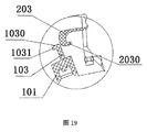
- FIG. 19 is a first schematic view showing the first state of the process of fitting the socket hook and the sheath buckle according to the present invention.
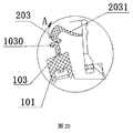
- FIG. 20 is a schematic view showing the second state of the process of fitting the socket hook and the sheath buckle according to the present invention.
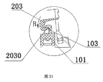
- FIG. 21 is a schematic view showing the third state of the process of fitting the socket hook and the sheath buckle according to the present invention.
- FIG. 22 is a fourth schematic view showing the process of fitting the socket hook and the sheath buckle according to the present invention.
- the invention discloses a safety injection needle, as shown in FIG. 1 and FIG. 2, which comprises an injection needle 1 which is composed of a needle holder 101 and a needle tube 102, which is different from the prior art in that the needle
- the seat 101 is connected to the safety cover 2 through a flexible folding mechanism 4.
- the side wall of the needle holder 101 is provided with two symmetrically distributed needle holders 103.
- the safety cover 2 has a long strip structure and is safe.
- the inner cavity of the protective cover 2 is hollow, and the lower end of the protective cover 2 is connected to one end of the elastic folding mechanism 4, and the other end of the elastic folding mechanism 4 is fixedly connected with the side wall of the needle holder 101, and the safety cover 2 is The upper end is suspended, and the safety cover 2 is turned over with the folding of the elastic folding mechanism 4, and the opening of the safety protection sleeve 2 near the needle tube 102 forms an opening 201, and the other side of the safety protection sleeve 2 opposite to the opening 201 is Form a closed surface 202, the hollow inner cavity of the safety protective sleeve 2 is provided with two symmetrically distributed sheath buckles 203, and the buckle 203 has a root portion 2031 which can be bounced (no other materials are needed, only the part needs to be made)
- the two sheath buckles 203 are matched with the two needle seat hooks 103, and the outer side of the sheath buckles 203 are provided with a sheath buckle. Stop 204.
- the upper end portion of the needle holder hook 103 is formed with a hook end 1031 bent toward one side
- the sheath buckle 203 is composed of an elastic root portion 2031 and a buckle end portion 2030, and the sheath buckle 203
- the buckle end 2030 forms a bend of the closing surface 202
- the initial contact point of the needle hook 103 and the sheath buckle 203 is a bend of the hook end and a bend of the buckle end 2030, and the hook The end is opposite to the direction in which the buckle end 2030 is bent.
- the structural design can ensure that when the needle seat hook 103 and the sheath buckle 203 are in initial contact, the touch surfaces of the two are curved surfaces of two arcs, or one of them is a curved surface of a circular arc, the purpose is to The thrust that triggers the occlusion of both is minimized.
- the sheath buckle 203 has an elastic root portion 2031.
- the needle seat hook 103 is pressed against the sheath buckle 203, and the elastic root portion 2031 is inclined in the direction of the top of the needle holder hook 103 (direction A in FIG. 20).
- the sheath buckle 203 rebounds in the direction of FIG. 21 and is buckled into the needle holder 103.
- the force of the buckle is verified by experiments to be only about 0.5N. This technical feature is currently not possible with similar products on the market. (Partial enlargement is shown in Figure 19- Figure 21)
- the hook 103 pulls the buckle 203 in the direction of FIG. 22, and the elastic root of the buckle 203 is inclined in the direction of C.
- the safety sheath and the needle seat are The opening force becomes: 1.
- the force of the deformation of the head of the buckle 203 is deformed and slipped. We can thicken the plastic of the head of the hook 203 and become difficult to deform; 2.
- the head of the hook 103 is deformed and slipped, but one side of the hook 103 is fixed on the needle seat and will not be deformed.
- the opening force is very large.
- the sheath snap block 204 defines the end of the sheath buckle 203 between the edge of the safety cover 2 and the needle seat, so that the protection The end of the sleeve 203 cannot be deflected left and right to prevent the sheath buckle 203 from slipping off from both sides of the needle holder 103, and The sheath buckle 203 cooperates with the sheath snap blocks 204 on both sides to form a continuous blocking structure for the needle holder hooks 103.
- the elastic folding mechanism 4 is composed of a fixed connecting plate 401 and a right angle connecting plate 402.
- the fixed connecting plate 401 is vertically and fixedly connected to the side wall of the needle holder 101, and the other end of the fixed connecting plate 401 and the right angle connecting plate 402 are fixed.
- One end of the right angle connecting plate 402 is fixedly connected to the lower end of the safety protective cover 2, and the joint of the fixed connecting plate 401 and the right angle connecting plate 402 forms a crease line 403, and the right angle connecting plate 402 is inverted along the crease line 403.
- a reinforcing rib 104 is disposed at each of the two outer walls of the upper portion of the upper portion of the needle holder 101, and the needle seat hook 103 is disposed at the top end of the reinforcing rib 104.
- the closing surface 202 is composed of an upper portion 2021 and a lower portion 2022.
- the connection between the upper portion 2021 and the lower portion 2022 is a continuous curved surface 2023, and the upper portion 2021 and the lower portion 2022 form an inner portion of less than 178 degrees and greater than 120 degrees. Angle.
- the design structure can ensure that the needle tube is compressed and bent in the occluded state, and forms a reverse force on the inner wall of the closed surface 202 to increase the firmness coefficient. At the same time, the design structure can also minimize the volume of the product, which is conducive to packaging and transportation.
- a hollow tube fixing hook 205 is disposed in the hollow inner cavity of the safety protective sleeve 2, and the needle tube fixing hook 205 is matched with the needle tube 102.
- the sheath buckle forms a directional force C under the release of the saving force B, and under the action of the hook, the needle holder hook is hung and interlocked to complete the hooking action of the two.
- the above process is the action of the safety cover and the injection needle being engaged. Step, because the sheath buckle is deformed by the force to complete the hook, the magnitude of the force deformation force is related to the operation feel, because the deformation part of the sheath buckle is very thin, after the test calculation, the force value is very small, about 0.5N, the operation feel Very mild and very comfortable for clinical use.
- the bite between the sheath buckle and the needle seat hook is a barbed type.
- the stability is excellent, very firm and the only failure. It may only be that the buckle and the hook are deformed or broken. After testing and taking into account the characteristics of the material itself, the deformation release force value needs to reach 15N or more (regardless of the force value of the needle tube disengagement). Both the safety factor and the stability factor of the instrument have reached the expected effect value.
- the injection needle 1 is connected to the blood collection tube 5.
- the injection needle 1 is connected to the insulin pen 6.
- the needle holder hook 103 is formed by thermal deformation at the upper end of the rib 104.
- the utility model has the advantages that the mold structure is simple, the mold release rate is high, and the heat deformation is completed at the time of product assembly.
- the hub hook 103 is formed at the upper end of the rib 104 by a Haval mold. Its characteristic is that it can be molded by one injection molding.
Landscapes
- Health & Medical Sciences (AREA)
- Life Sciences & Earth Sciences (AREA)
- Engineering & Computer Science (AREA)
- Animal Behavior & Ethology (AREA)
- Hematology (AREA)
- Veterinary Medicine (AREA)
- Public Health (AREA)
- Biomedical Technology (AREA)
- Heart & Thoracic Surgery (AREA)
- General Health & Medical Sciences (AREA)
- Pathology (AREA)
- Surgery (AREA)
- Molecular Biology (AREA)
- Medical Informatics (AREA)
- Biophysics (AREA)
- Physics & Mathematics (AREA)
- Vascular Medicine (AREA)
- Anesthesiology (AREA)
- Environmental & Geological Engineering (AREA)
- Infusion, Injection, And Reservoir Apparatuses (AREA)
Abstract
Description
Claims (11)
- 一种安全注射针,它包括注射针(1),所述注射针(1)由针座(101)和针管(102)构成,其特征在于:所述针座(101)通过一弹性翻折机构(4)与安全保护套(2)连接,针座(101)的侧壁上设有两个对称分布的针座卡勾(103),所述安全保护套(2)整体呈长条状结构,安全保护套(2)的内腔呈中空状,安全保护套(2)的下端与上述弹性翻折机构(4)的一端连接,弹性翻折机构(4)的另一端与针座(101)的侧壁固定连接,安全保护套(2)的上端呈悬空状,安全保护套(2)随弹性翻折机构(4)的翻折而翻转,安全保护套(2)靠近上述针管(102)的一侧形成开口(201),安全保护套(2)处与开口(201)相对的另一侧呈形成一封闭面(202),安全保护套(2)中空的内腔中设有两个对称分布的护套卡扣(203),所述的两个护套卡扣(203)与上述两个针座卡勾(103)相配合,护套卡扣(203)的外侧均设有一护套卡扣挡块(204)。
- 根据权利要求1所述的一种安全注射针,其特征在于:所述针座卡勾(103)的上端部形成向一侧折弯的勾端(1031),护套卡扣(203)由具有弹性的根部(2031)和卡扣端部(2030)构成,护套卡扣(203)的卡扣端部(2030)形成一向封闭面(202)的折弯,针座卡勾(103)与护套卡扣(203)的初始接触点为勾端的折弯处和卡扣端部(2030)的折弯处,并且,勾端与卡扣端部(2030)的折弯方向相反。
- 根据权利要求2所述的一种安全注射针,其特征在于:所述勾端(1031)与卡扣端部(2030)咬合时,护套卡扣挡块(204)将护套卡扣(203)的端部限定于安全保护套(2)边沿和针座之间,使得护套卡扣(203)的端部不能左右偏离,防止护套卡扣(203)从针座卡勾(103)的两侧滑脱,并且,护套卡扣(203)与两侧的护套卡扣挡块(204)配合对针座卡勾(103)形成一连续 的阻挡结构。
- 根据权利要求1所述的一种安全注射针,其特征在于:所述弹性翻折机构(4)由固定连接板(401)和直角连接板(402)构成,固定连接板(401)与针座(101)侧壁垂直固定连接,固定连接板(401)的另一端与直角连接板(402)的一端连接,直角连接板(402)的另一端与安全保护套(2)的下端固定连接,固定连接板(401)与直角连接板(402)的连接处形成折痕线(403),直角连接板(402)沿折痕线(403)翻转。
- 根据权利要求1所述的一种安全注射针,其特征在于:所述针座(101)上段的两侧外壁处各设有一条加强筋(104),上述针座卡勾(103)设置于加强筋(104)的顶端处。
- 根据权利要求1所述的一种安全注射针,其特征在于:所述封闭面(202)由上部(2021)和下部(2022)构成,上部(2021)和下部(2022)的连接处为连续的弧面(2023),上部(2021)和下部(2022)之间形成小于178度并大于120度的内夹角。
- 根据权利要求1所述的一种安全注射针,其特征在于:所述安全保护套(2)中空的内腔中设有一针管固定钩(205),该针管固定钩(205)与上述针管(102)相配合。
- 根据权利要求1所述的一种安全注射针,其特征在于:所述注射针(1)与采血管(5)连接。
- 根据权利要求1所述的一种安全注射针,其特征在于:所述注射针(1)与胰岛素笔(6)连接。
- 根据权利要求1所述的一种安全注射针,其特征在于:所述针座卡勾(103)在加强筋(104)上端通过热变形成形。
- 根据权利要求1所述的一种安全注射针,其特征在于:所述针座卡勾(103)在加强筋(104)上端通过哈弗模具成形。
Priority Applications (7)
| Application Number | Priority Date | Filing Date | Title |
|---|---|---|---|
| ES16921192T ES2930851T3 (es) | 2016-11-11 | 2016-12-15 | Aguja de inyección segura |
| RU2019118213A RU2729549C1 (ru) | 2016-11-11 | 2016-12-15 | Безопасная инъекционная игла |
| KR1020197014505A KR20190080895A (ko) | 2016-11-11 | 2016-12-15 | 안전 주사 바늘 |
| BR112019009528-4A BR112019009528B1 (pt) | 2016-11-11 | 2016-12-15 | Agulha de injeção de segurança |
| US16/349,285 US11033213B2 (en) | 2016-11-11 | 2016-12-15 | Secure injection needle |
| EP16921192.7A EP3539598B1 (en) | 2016-11-11 | 2016-12-15 | Secure injection needle |
| CA3046821A CA3046821C (en) | 2016-11-11 | 2016-12-15 | Safety injection needle |
Applications Claiming Priority (2)
| Application Number | Priority Date | Filing Date | Title |
|---|---|---|---|
| CN201610993369.6A CN106730172B (zh) | 2016-11-11 | 2016-11-11 | 一种安全注射针 |
| CN201610993369.6 | 2016-11-11 |
Publications (1)
| Publication Number | Publication Date |
|---|---|
| WO2018086192A1 true WO2018086192A1 (zh) | 2018-05-17 |
Family
ID=58973245
Family Applications (1)
| Application Number | Title | Priority Date | Filing Date |
|---|---|---|---|
| PCT/CN2016/110122 Ceased WO2018086192A1 (zh) | 2016-11-11 | 2016-12-15 | 一种安全注射针 |
Country Status (9)
| Country | Link |
|---|---|
| US (1) | US11033213B2 (zh) |
| EP (1) | EP3539598B1 (zh) |
| KR (1) | KR20190080895A (zh) |
| CN (1) | CN106730172B (zh) |
| BR (1) | BR112019009528B1 (zh) |
| CA (1) | CA3046821C (zh) |
| ES (1) | ES2930851T3 (zh) |
| RU (1) | RU2729549C1 (zh) |
| WO (1) | WO2018086192A1 (zh) |
Families Citing this family (13)
| Publication number | Priority date | Publication date | Assignee | Title |
|---|---|---|---|---|
| CN107737391A (zh) * | 2017-11-08 | 2018-02-27 | 温州京环科技有限公司 | 安全式注射针 |
| CN108634967A (zh) * | 2018-05-21 | 2018-10-12 | 安徽宏宇五洲医疗器械股份有限公司 | 笔式安全采血针及使用方法 |
| US20220305214A1 (en) | 2019-06-21 | 2022-09-29 | Becton Dickinson France | Safety Device for Preventing Needle Stick Injury with a Needle of a Medical Injection Device |
| CN216136491U (zh) * | 2020-02-21 | 2022-03-29 | 贝克顿·迪金森公司 | 与针头组件一起使用的针头防护组件 |
| EP4168074A1 (en) * | 2020-06-23 | 2023-04-26 | Becton Dickinson France | Safety device for a needle |
| CN112386770B (zh) * | 2020-10-27 | 2025-06-06 | 张亚平 | 一种安全注射针 |
| CN112472924B (zh) * | 2020-12-17 | 2024-08-13 | 求精医疗器械(浙江)有限公司 | 注射针防护装置 |
| CN113144349A (zh) * | 2021-04-30 | 2021-07-23 | 贝普医疗科技股份有限公司 | 一种防针刺护罩组件 |
| CN112999469A (zh) * | 2021-05-06 | 2021-06-22 | 山东威高集团医用高分子制品股份有限公司 | 一种注射器和具有保护罩的针座 |
| WO2022242838A1 (en) * | 2021-05-18 | 2022-11-24 | Terumo Europe N.V. | Safety needle assembly |
| CN113209413A (zh) * | 2021-05-28 | 2021-08-06 | 鹰潭荣嘉集团医疗器械实业有限公司 | 非邻笨精密输液器 |
| CN115554528B (zh) * | 2022-09-29 | 2026-04-03 | 宁波美生医疗器材有限公司 | 一种胰岛素笔配套用针的插瓶端防针刺安全结构 |
| TWI883963B (zh) * | 2024-05-17 | 2025-05-11 | 蔡溪進 | 用於採血器的防止針具被推出或外露的防針扎裝置 |
Citations (6)
| Publication number | Priority date | Publication date | Assignee | Title |
|---|---|---|---|---|
| US5242417A (en) * | 1992-01-13 | 1993-09-07 | Paudler Gary M | Self closing hinged syringe guard |
| CN101282755A (zh) * | 2005-05-27 | 2008-10-08 | 史密斯医疗Asd公司 | 具有卡合特征的安全针装置及其制造方法 |
| CN202724375U (zh) * | 2011-05-06 | 2013-02-13 | 上海萌黎国际贸易有限公司 | 安全针组件 |
| CN202724380U (zh) * | 2012-08-31 | 2013-02-13 | 浙江康德莱医疗器械股份有限公司 | 安全注射针保护套 |
| CN203196091U (zh) * | 2013-03-12 | 2013-09-18 | 淮安市恒春医疗器材有限公司 | 带针头保护装置的安全注射器 |
| CN203694278U (zh) * | 2014-02-09 | 2014-07-09 | 广东海鸥医疗器械股份有限公司 | 一种注射器注射针安全保护套 |
Family Cites Families (20)
| Publication number | Priority date | Publication date | Assignee | Title |
|---|---|---|---|---|
| CA2157999C (en) * | 1994-09-23 | 1999-08-03 | Robert B. Odell | Manually pivoted barrier assembly for a piercing element |
| US8226617B2 (en) * | 1999-11-04 | 2012-07-24 | Tyco Healthcare Group Lp | Safety shield apparatus and mounting structure for use with medical needle devices |
| US6582397B2 (en) * | 2001-06-19 | 2003-06-24 | Portex, Inc. | Needle safety device with antiremoval protection |
| CA2551698C (en) * | 2004-01-07 | 2016-05-24 | Smiths Medical Asd, Inc. | Needle protection device with gauge specific color coding and method for manufacturing thereof |
| US8057431B2 (en) * | 2006-12-21 | 2011-11-15 | B. Braun Melsungen Ag | Hinged cap for needle device |
| AU2008273945B2 (en) * | 2007-07-12 | 2013-05-16 | Star Syringe Limited | Needlestick prevention device |
| CN102363056B (zh) * | 2011-08-01 | 2013-06-05 | 上海萌黎国际贸易有限公司 | 针头保护装置和安全针组件 |
| SE536565C2 (sv) * | 2012-06-29 | 2014-02-25 | Margaretha Mathiasson | Nålskydd vid kanyler |
| DK2705861T3 (en) * | 2012-09-05 | 2015-07-20 | Becton Dickinson France | Automatic injection device |
| CN103405831B (zh) * | 2012-10-30 | 2015-07-08 | 张林锋 | 一种安全注射针 |
| CN103285458A (zh) * | 2013-05-31 | 2013-09-11 | 浙江康德莱医疗器械股份有限公司 | 安全保护套 |
| CN103908267A (zh) * | 2014-03-26 | 2014-07-09 | 温州市贝普科技有限公司 | 一种安全采血针 |
| CN203841704U (zh) * | 2014-03-26 | 2014-09-24 | 温州市贝普科技有限公司 | 一种安全采血针 |
| CN103908710A (zh) * | 2014-03-26 | 2014-07-09 | 温州市贝普科技有限公司 | 一种安全注射器 |
| CN104117117B (zh) * | 2014-08-06 | 2017-02-08 | 江苏康宝医疗器械有限公司 | 注射针的安全保护装置 |
| WO2016039111A1 (ja) * | 2014-09-11 | 2016-03-17 | テルモ株式会社 | シリンジ用組立体、シリンジ用組立体包装体、外筒用シールキャップおよびプレフィルドシリンジ |
| GB2532979A (en) * | 2014-12-04 | 2016-06-08 | Owen Mumford Ltd | Needle assemblies |
| CN106031806B (zh) * | 2015-03-09 | 2020-12-08 | 河南曙光健士医疗器械集团股份有限公司 | 针头安全保护套结构 |
| CN205287134U (zh) * | 2015-12-30 | 2016-06-08 | 安徽天康医疗科技股份有限公司 | 装配方便的高可靠性安全针 |
| CN206548942U (zh) * | 2016-11-11 | 2017-10-13 | 贝普医疗科技有限公司 | 一种安全注射针 |
-
2016
- 2016-11-11 CN CN201610993369.6A patent/CN106730172B/zh active Active
- 2016-12-15 RU RU2019118213A patent/RU2729549C1/ru active
- 2016-12-15 KR KR1020197014505A patent/KR20190080895A/ko not_active Ceased
- 2016-12-15 WO PCT/CN2016/110122 patent/WO2018086192A1/zh not_active Ceased
- 2016-12-15 ES ES16921192T patent/ES2930851T3/es active Active
- 2016-12-15 EP EP16921192.7A patent/EP3539598B1/en active Active
- 2016-12-15 BR BR112019009528-4A patent/BR112019009528B1/pt active IP Right Grant
- 2016-12-15 US US16/349,285 patent/US11033213B2/en active Active
- 2016-12-15 CA CA3046821A patent/CA3046821C/en active Active
Patent Citations (6)
| Publication number | Priority date | Publication date | Assignee | Title |
|---|---|---|---|---|
| US5242417A (en) * | 1992-01-13 | 1993-09-07 | Paudler Gary M | Self closing hinged syringe guard |
| CN101282755A (zh) * | 2005-05-27 | 2008-10-08 | 史密斯医疗Asd公司 | 具有卡合特征的安全针装置及其制造方法 |
| CN202724375U (zh) * | 2011-05-06 | 2013-02-13 | 上海萌黎国际贸易有限公司 | 安全针组件 |
| CN202724380U (zh) * | 2012-08-31 | 2013-02-13 | 浙江康德莱医疗器械股份有限公司 | 安全注射针保护套 |
| CN203196091U (zh) * | 2013-03-12 | 2013-09-18 | 淮安市恒春医疗器材有限公司 | 带针头保护装置的安全注射器 |
| CN203694278U (zh) * | 2014-02-09 | 2014-07-09 | 广东海鸥医疗器械股份有限公司 | 一种注射器注射针安全保护套 |
Non-Patent Citations (1)
| Title |
|---|
| See also references of EP3539598A4 |
Also Published As
| Publication number | Publication date |
|---|---|
| EP3539598A4 (en) | 2020-09-09 |
| US20190343439A1 (en) | 2019-11-14 |
| EP3539598B1 (en) | 2022-11-02 |
| CN106730172A (zh) | 2017-05-31 |
| RU2729549C1 (ru) | 2020-08-07 |
| ES2930851T3 (es) | 2022-12-22 |
| BR112019009528A2 (pt) | 2019-07-30 |
| BR112019009528B1 (pt) | 2023-04-18 |
| CA3046821A1 (en) | 2018-05-17 |
| US11033213B2 (en) | 2021-06-15 |
| KR20190080895A (ko) | 2019-07-08 |
| EP3539598A1 (en) | 2019-09-18 |
| CA3046821C (en) | 2022-05-31 |
| CN106730172B (zh) | 2023-05-23 |
Similar Documents
| Publication | Publication Date | Title |
|---|---|---|
| WO2018086192A1 (zh) | 一种安全注射针 | |
| US10155105B2 (en) | Tubing clamp | |
| CN209499742U (zh) | 一种针头自动回缩式采血针 | |
| CN103796698A (zh) | 具有活动状态和被动状态的护针器 | |
| JPH04261665A (ja) | 翼付針 | |
| CN104640470A (zh) | 可释放带扣 | |
| JP7413643B2 (ja) | 医療用針 | |
| WO2014036926A1 (zh) | 一种安全手术刀 | |
| KR20200016947A (ko) | 침 헤드 수동 리트랙션 타입 정맥 수액 침 | |
| US10765176B2 (en) | Personal protective device strap connecting buckle assembly | |
| CN206548942U (zh) | 一种安全注射针 | |
| CN204016400U (zh) | 用于夹持组织的钛夹 | |
| CN204910322U (zh) | 一种自锁式医用穿刺针 | |
| CN103301527B (zh) | 蝴蝶针组安全针套 | |
| CN220520095U (zh) | 医用拉环开启器 | |
| CN106390233A (zh) | 一种一次性使用自动弹出式医用针 | |
| CN217592178U (zh) | 一种滑动拉链和服装 | |
| EP2999512B1 (en) | Locking cannula for medical lines | |
| CN218944044U (zh) | 穿刺或药液输注针体的锁尖装置 | |
| CN105056340A (zh) | 安全式医用穿刺针及使用方法 | |
| CN205306154U (zh) | 一种隐形拉链的拉头 | |
| CN102525040A (zh) | 无拉手拉链 | |
| CN107281587B (zh) | 一种针头安全回缩静脉输液针 | |
| CN208625713U (zh) | 一种针头自动回缩式采血针 | |
| CN209474688U (zh) | 一体化简易单孔腹腔镜套管 |
Legal Events
| Date | Code | Title | Description |
|---|---|---|---|
| 121 | Ep: the epo has been informed by wipo that ep was designated in this application |
Ref document number: 16921192 Country of ref document: EP Kind code of ref document: A1 |
|
| NENP | Non-entry into the national phase |
Ref country code: DE |
|
| ENP | Entry into the national phase |
Ref document number: 20197014505 Country of ref document: KR Kind code of ref document: A |
|
| REG | Reference to national code |
Ref country code: BR Ref legal event code: B01A Ref document number: 112019009528 Country of ref document: BR |
|
| ENP | Entry into the national phase |
Ref document number: 3046821 Country of ref document: CA |
|
| ENP | Entry into the national phase |
Ref document number: 2016921192 Country of ref document: EP Effective date: 20190610 |
|
| ENP | Entry into the national phase |
Ref document number: 112019009528 Country of ref document: BR Kind code of ref document: A2 Effective date: 20190510 |