WO2018087908A1 - 電動ポンプ装置 - Google Patents
電動ポンプ装置 Download PDFInfo
- Publication number
- WO2018087908A1 WO2018087908A1 PCT/JP2016/083646 JP2016083646W WO2018087908A1 WO 2018087908 A1 WO2018087908 A1 WO 2018087908A1 JP 2016083646 W JP2016083646 W JP 2016083646W WO 2018087908 A1 WO2018087908 A1 WO 2018087908A1
- Authority
- WO
- WIPO (PCT)
- Prior art keywords
- motor
- rotational speed
- control
- temperature
- oil
- Prior art date
- Legal status (The legal status is an assumption and is not a legal conclusion. Google has not performed a legal analysis and makes no representation as to the accuracy of the status listed.)
- Ceased
Links
Images


Classifications
-
- F—MECHANICAL ENGINEERING; LIGHTING; HEATING; WEAPONS; BLASTING
- F04—POSITIVE - DISPLACEMENT MACHINES FOR LIQUIDS; PUMPS FOR LIQUIDS OR ELASTIC FLUIDS
- F04B—POSITIVE-DISPLACEMENT MACHINES FOR LIQUIDS; PUMPS
- F04B17/00—Pumps characterised by combination with, or adaptation to, specific driving engines or motors
- F04B17/03—Pumps characterised by combination with, or adaptation to, specific driving engines or motors driven by electric motors
-
- F—MECHANICAL ENGINEERING; LIGHTING; HEATING; WEAPONS; BLASTING
- F04—POSITIVE - DISPLACEMENT MACHINES FOR LIQUIDS; PUMPS FOR LIQUIDS OR ELASTIC FLUIDS
- F04B—POSITIVE-DISPLACEMENT MACHINES FOR LIQUIDS; PUMPS
- F04B49/00—Control, e.g. of pump delivery, or pump pressure of, or safety measures for, machines, pumps, or pumping installations, not otherwise provided for, or of interest apart from, groups F04B1/00 - F04B47/00
- F04B49/06—Control using electricity
-
- F—MECHANICAL ENGINEERING; LIGHTING; HEATING; WEAPONS; BLASTING
- F04—POSITIVE - DISPLACEMENT MACHINES FOR LIQUIDS; PUMPS FOR LIQUIDS OR ELASTIC FLUIDS
- F04B—POSITIVE-DISPLACEMENT MACHINES FOR LIQUIDS; PUMPS
- F04B49/00—Control, e.g. of pump delivery, or pump pressure of, or safety measures for, machines, pumps, or pumping installations, not otherwise provided for, or of interest apart from, groups F04B1/00 - F04B47/00
- F04B49/02—Stopping, starting, unloading or idling control
-
- F—MECHANICAL ENGINEERING; LIGHTING; HEATING; WEAPONS; BLASTING
- F04—POSITIVE - DISPLACEMENT MACHINES FOR LIQUIDS; PUMPS FOR LIQUIDS OR ELASTIC FLUIDS
- F04B—POSITIVE-DISPLACEMENT MACHINES FOR LIQUIDS; PUMPS
- F04B49/00—Control, e.g. of pump delivery, or pump pressure of, or safety measures for, machines, pumps, or pumping installations, not otherwise provided for, or of interest apart from, groups F04B1/00 - F04B47/00
- F04B49/10—Other safety measures
- F04B49/103—Responsive to speed
-
- F—MECHANICAL ENGINEERING; LIGHTING; HEATING; WEAPONS; BLASTING
- F04—POSITIVE - DISPLACEMENT MACHINES FOR LIQUIDS; PUMPS FOR LIQUIDS OR ELASTIC FLUIDS
- F04B—POSITIVE-DISPLACEMENT MACHINES FOR LIQUIDS; PUMPS
- F04B49/00—Control, e.g. of pump delivery, or pump pressure of, or safety measures for, machines, pumps, or pumping installations, not otherwise provided for, or of interest apart from, groups F04B1/00 - F04B47/00
- F04B49/20—Control, e.g. of pump delivery, or pump pressure of, or safety measures for, machines, pumps, or pumping installations, not otherwise provided for, or of interest apart from, groups F04B1/00 - F04B47/00 by changing the driving speed
-
- H—ELECTRICITY
- H02—GENERATION; CONVERSION OR DISTRIBUTION OF ELECTRIC POWER
- H02P—CONTROL OR REGULATION OF ELECTRIC MOTORS, ELECTRIC GENERATORS OR DYNAMO-ELECTRIC CONVERTERS; CONTROLLING TRANSFORMERS, REACTORS OR CHOKE COILS
- H02P6/00—Arrangements for controlling synchronous motors or other dynamo-electric motors using electronic commutation dependent on the rotor position; Electronic commutators therefor
- H02P6/20—Arrangements for starting
- H02P6/21—Open loop start
-
- F—MECHANICAL ENGINEERING; LIGHTING; HEATING; WEAPONS; BLASTING
- F04—POSITIVE - DISPLACEMENT MACHINES FOR LIQUIDS; PUMPS FOR LIQUIDS OR ELASTIC FLUIDS
- F04B—POSITIVE-DISPLACEMENT MACHINES FOR LIQUIDS; PUMPS
- F04B2203/00—Motor parameters
- F04B2203/02—Motor parameters of rotating electric motors
-
- F—MECHANICAL ENGINEERING; LIGHTING; HEATING; WEAPONS; BLASTING
- F04—POSITIVE - DISPLACEMENT MACHINES FOR LIQUIDS; PUMPS FOR LIQUIDS OR ELASTIC FLUIDS
- F04B—POSITIVE-DISPLACEMENT MACHINES FOR LIQUIDS; PUMPS
- F04B2203/00—Motor parameters
- F04B2203/02—Motor parameters of rotating electric motors
- F04B2203/0201—Current
-
- F—MECHANICAL ENGINEERING; LIGHTING; HEATING; WEAPONS; BLASTING
- F04—POSITIVE - DISPLACEMENT MACHINES FOR LIQUIDS; PUMPS FOR LIQUIDS OR ELASTIC FLUIDS
- F04B—POSITIVE-DISPLACEMENT MACHINES FOR LIQUIDS; PUMPS
- F04B2203/00—Motor parameters
- F04B2203/02—Motor parameters of rotating electric motors
- F04B2203/0209—Rotational speed
-
- F—MECHANICAL ENGINEERING; LIGHTING; HEATING; WEAPONS; BLASTING
- F04—POSITIVE - DISPLACEMENT MACHINES FOR LIQUIDS; PUMPS FOR LIQUIDS OR ELASTIC FLUIDS
- F04B—POSITIVE-DISPLACEMENT MACHINES FOR LIQUIDS; PUMPS
- F04B2205/00—Fluid parameters
- F04B2205/10—Inlet temperature
-
- F—MECHANICAL ENGINEERING; LIGHTING; HEATING; WEAPONS; BLASTING
- F04—POSITIVE - DISPLACEMENT MACHINES FOR LIQUIDS; PUMPS FOR LIQUIDS OR ELASTIC FLUIDS
- F04B—POSITIVE-DISPLACEMENT MACHINES FOR LIQUIDS; PUMPS
- F04B2205/00—Fluid parameters
- F04B2205/14—Viscosity
-
- F—MECHANICAL ENGINEERING; LIGHTING; HEATING; WEAPONS; BLASTING
- F05—INDEXING SCHEMES RELATING TO ENGINES OR PUMPS IN VARIOUS SUBCLASSES OF CLASSES F01-F04
- F05B—INDEXING SCHEME RELATING TO WIND, SPRING, WEIGHT, INERTIA OR LIKE MOTORS, TO MACHINES OR ENGINES FOR LIQUIDS COVERED BY SUBCLASSES F03B, F03D AND F03G
- F05B2270/00—Control
- F05B2270/30—Control parameters, e.g. input parameters
Definitions
- the present invention relates to an electric pump device driven by an electric motor.
- an electric pump that supplies a medium such as cooling water, lubricating oil, or hydraulic oil to each part of the engine (a cooling target part, a lubrication target part, and an operation target part) by rotation of an electric motor.
- the discharge amount of the electric pump varies depending on the rotation speed (rotational speed) of the motor.
- a technique for driving the motor by feedback control that converges the actual rotational speed of the motor to the steady rotational speed has been widely put into practical use ( For example, see Patent Document 1).
- This invention is made
- an electric pump device includes a fluid pump that discharges fluid, a motor that drives the fluid pump, and a current value supplied to the motor to control rotation of the motor.
- the control device is configured such that when the motor is started, the rotation speed of the motor is a preset target rotation speed.
- the motor is driven by open loop control in which the current value supplied to the motor is limited to a predetermined upper limit value or less until it reaches the vicinity, and when the rotational speed of the motor reaches the vicinity of the target rotational speed, The motor is driven by feedback control in which the rotational speed is maintained at a steady rotational speed.
- the control device is preset with a command rotational speed for the motor, and in the open loop control, the command rotational speed of the motor is increased stepwise, It is preferable that the motor is configured to supply a current value corresponding to the command rotational speed.
- the electric pump device includes a temperature detector that detects the temperature of the fluid, and when the motor is started, when the temperature of the fluid detected by the temperature detector is less than a specified temperature, The open loop control is executed for a relatively long time, and when the temperature of the fluid detected by the temperature detecting means is equal to or higher than a specified temperature, the open loop control is executed for a relatively short time. It is preferable.
- the motor is controlled by open loop control in which the current value supplied to the motor is limited to a value lower than the predetermined upper limit value until the motor speed reaches the vicinity of the target speed. Because it drives, the load at the start of the motor can be reduced and the output of the motor can be suppressed. As a result, the rated output of the electric pump can be achieved even when the fluid is relatively viscous, such as during cold start. It becomes possible to start stably without exceeding.
- the temperature of the fluid is gradually increased as time passes without increasing the load of the fluid pump by increasing the command rotational speed of the motor stepwise (The viscous resistance of the fluid can be gradually reduced), and the electric pump device can be started up efficiently.
- the open loop control when the temperature of the fluid is lower than the specified temperature, the open loop control is executed for a relatively long time before the shift to the feedback control, and when the temperature of the fluid is higher than the specified temperature, it is opened.
- optimal control according to the physical properties (viscous resistance) of the fluid can be performed, and the motor can be used without consuming unnecessary power. Can be quickly brought to steady rotation.
- FIG. 1 An electric pump 1 according to an embodiment of the present invention is shown in FIG. 1. First, a schematic configuration of the electric pump 1 according to the present embodiment will be described with reference to FIG. 1.
- the electric pump 1 mainly includes an oil pump 10 that discharges oil, a motor 20 as a drive source that drives the oil pump 10, and a control device (also referred to as “driver”) 30 that controls the rotation of the motor 20. Configured.
- the discharge amount (flow rate) of the oil pump 10 increases and decreases according to the rotational speed of the motor 20. That is, the discharge amount of the oil pump 10 increases as the rotation speed of the motor 20 increases, and the discharge amount of the oil pump 10 decreases as the rotation speed of the motor 20 decreases.
- the oil pump 10 is connected to a rotating shaft of the motor 20 and sucks oil from an oil tank (not shown) by a driving force (rotating force) transmitted from the motor 20 to externally (cooling system, lubricating system, operating system). ).
- the oil discharged from the oil pump 10 to the outside is returned to the oil tank and circulated.
- a gear pump that discharges fluid according to rotation of a pair of gears that mesh with each other, a centrifugal pump that discharges fluid according to rotation of an impeller (impeller), and the like are applied.
- the motor 20 is, for example, a three-phase brushless DC motor, and includes a three-phase (U-phase, V-phase, W-phase) coil, and a rotor made of permanent magnets magnetized in N and S poles. .
- the motor 20 is configured such that the rotor rotates by sequentially switching energization to the coils of each phase.
- the motor 20 of this example is a so-called sensorless type brushless DC motor that does not use a position detecting element such as a Hall element, and rotates the rotor using an induced voltage (back electromotive force) generated in each coil. The position is detected, and the energization to each phase is switched from the magnetic pole position information obtained based on the position. Since such a DC brushless motor has been conventionally known, detailed description thereof is omitted here.
- the control device 30 includes a drive circuit 31 that drives the motor 20 and a microcomputer (hereinafter simply referred to as “microcomputer”) 32 that controls the drive circuit 31.
- the control device 30 is configured as a control board on which various electronic / electrical components are mounted.
- the control device 30 or a part of the control device 30 may be configured separately from the electric pump 1.
- the drive circuit 31 is a driver configured by connecting switching elements corresponding to each phase (U phase, V phase, W phase) of the motor 20 in parallel to the battery (power source) 40.
- the switching element of the drive circuit 31 is turned on / off based on a motor control signal (PWM signal) transmitted from the microcomputer 32 of the host device, thereby supplying current (three-phase excitation current) to the motor 20. Then, the motor 20 is driven to rotate.
- PWM signal motor control signal
- a MOSFET or the like is preferably used as the switching element, but other transistors may be used.
- the microcomputer 32 transmits a motor control signal (PWM signal) corresponding to the command rotational speed set in the control table or the like to the drive circuit 31, and performs on / off control of the switching elements of each phase of the drive circuit 31.
- the motor 20 is PWM-controlled.
- the microcomputer 32 controls the duty ratio of the motor control signal, thereby controlling the current value supplied to the coils of the respective phases of the motor 20 (pseudo-controlling the voltage applied to the motor 20).
- the number of rotations of the motor 20 is increased or decreased. That is, the microcomputer 32 controls the amount of current supplied to the motor 20 (that is, the rotation speed of the motor 20) using the duty ratio of the PWM signal output to the drive circuit 31 as a control amount.
- the microcomputer 32 detects the actual rotation speed (referred to as “actual rotation speed”) of the motor 20 by using the induced voltage (back electromotive force) generated in the coil of each phase of the motor 20 as an input.
- the microcomputer 32 is electrically connected to an oil temperature detector (oil temperature sensor) 50 that detects the temperature of the oil, and is configured to receive detection information of the oil temperature detector 50.
- Oil has the property that the viscosity changes according to the oil temperature, and the viscosity increases (viscosity resistance increases) as the oil temperature decreases.
- the oil temperature detector 50 in this example functions as a viscosity estimating means for estimating the viscosity (physical properties) of the oil based on the temperature of the oil.
- the oil temperature detector 50 may be mounted inside the electric pump 1.
- the oil temperature detector 50 may be either a contact type or a non-contact type.
- the microcomputer 32 selectively switches the control method of the motor 20 to open loop control or closed loop control (feedback control), and drives the motor 20.
- the microcomputer 32 reaches the preset target rotational speed (hereinafter referred to as “feedback transition rotational speed”).
- feedback transition rotational speed the preset target rotational speed
- the open loop control is a control method for driving the motor 20 at a preset command rotational speed (duty ratio).
- the command rotational speed (duty ratio of the motor control signal) is stepwise so that the current value supplied to the coil of each phase of the motor 20 does not exceed a predetermined upper limit value (rated current value).
- the number of rotations of the motor 20 is gradually increased by increasing (increase gradually).
- Various types of information used for the open loop control are stored in a control table set in the storage unit of the control device 30.
- a control table a low temperature control table (see FIG. 3) set when the oil temperature (detected oil temperature) is lower than the specified temperature, and the oil temperature (detected oil temperature).
- a high temperature control table (not shown) set when the temperature is equal to or higher than the specified temperature is prepared.
- the low temperature control table is set, the feedback control is executed for a relatively long time.
- feedback control is executed for a relatively short time. That is, in the low temperature control table, the driving time of the motor 20 by the open loop control is set to be a long time (for example, about 10 times longer) than the high temperature control table.
- the microcomputer 32 maintains the actual rotational speed at the steady rotational speed (the deviation between the actual rotational speed and the steady rotational speed).
- the motor 20 is driven by feedback control so that becomes zero.
- the microcomputer 32 executes the feedback control for a relatively short time when the oil temperature is equal to or higher than the specified temperature when the electric pump 1 is started, and the actual rotational speed of the motor 20 reaches the feedback transition rotational speed. When this happens, the system shifts to feedback control.
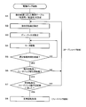
- FIG. 2 is a flowchart showing a flow of operation processing at the time of starting the electric pump 1
- FIG. 3 is a schematic diagram showing a control table for low temperature
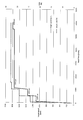
- FIG. 4 is a command rotation speed with respect to an elapsed time after starting the electric pump 1. It is a graph which shows the mode of a change of a duty ratio (when the control table for low temperature is set). Note that the processing of this flowchart is repeatedly executed at a predetermined cycle (for example, every 10 ms).
- the control device 30 sets a control table (a low temperature control table or a high temperature control table) corresponding to the temperature of the oil detected by the oil temperature detector 50 (step S1). Specifically, the control device 30 determines whether or not the temperature of the oil detected by the oil temperature detector 50 is lower than a specified temperature, and sets the control table for low temperature when the temperature is lower than the specified temperature. When the temperature is higher than the specified temperature, a high temperature control table (not shown) is set. The specified temperature is set based on the characteristics of the electric pump 1, the type of oil, the usage environment, and the like. Hereinafter, a case where a low temperature control table (FIG. 3) is set will be described as an example.
- a low temperature control table FIG. 3
- the control device 30 refers to the control table and sets the first command rotational speed (step S2).
- the control table includes a command rotation speed of the motor 20, a duty ratio with respect to the command rotation speed, and a drive time of the motor 20 at the command rotation speed (referred to as “specified drive time”).
- the control device 30 reads the first command rotational speed (first command rotational speed) from the control table, and sets 50 rpm as the current command rotational speed.
- a rotation speed from the initial rotation speed (50 rpm) to the feedback transfer rotation speed (1800) rpm is set as the command rotation speed.
- the duty ratio is set in a range in which the current value supplied to the motor 20 does not exceed the rated current value (maximum rated current value).
- control device 30 refers to the control table and sets a duty ratio according to the current command rotational speed (step S3). Specifically, the control device 30 reads the duty ratio corresponding to the first command rotational speed (50 rpm) from the control table, and sets 18% as the duty ratio of the motor control signal.
- the control device 30 drives the motor 20 based on the PWM control based on the duty ratio set in step S3 (step S4).
- the magnitude of the duty ratio in the PWM control is related to the increase / decrease in the current value supplied to the motor 20 (that is, the increase / decrease in the rotation speed of the motor 20).
- the control device 30 refers to the control table and determines whether or not the motor 20 has been driven for the specified drive time at the current command rotational speed (step S5). Specifically, the control device 30 determines whether or not the motor 20 has been driven for the specified drive time (10 ms) at the current command rotation speed (50 rpm). In the present embodiment, 10 ms is basically set as the specified drive time of the motor 20 for each commanded rotational speed. However, as shown in FIGS. 3 and 4, at a predetermined command rotational speed (1100 rpm, 1350 rpm, 1750 rpm), the specified drive time is relative to promote the temperature rise of the oil through the circulation (replacement) of the oil. Set to a long time.
- the command rotational speed is gradually increased every minute time (10 ms), and when the predetermined command rotational speed is reached, the motor 20 is set to a relatively long time. By driving it over the course, the temperature rise of the oil is promoted while preventing the motor 20 from stepping out and overloading.
- Control device 30 determines whether or not the command rotational speed set in step S2 has reached the feedback transition rotational speed (step S6) when the motor 20 is driven for the specified drive time (step S5: YES). At this stage, since the command rotational speed (initial command rotational speed: 50 rpm) is less than the feedback transition rotational speed (1800 rpm), the process returns to step S2.
- control device 30 refers to the control table and sets the next command rotational speed (step S2). Specifically, the control device 30 reads the next command rotational speed (second command rotational speed) from the control table, and sets 60 rpm as the current command rotational speed.
- control device 30 refers to the control table and sets a duty ratio according to the current command rotational speed (step S3). Specifically, the control device 30 reads the duty ratio corresponding to the second command rotation speed (60 rpm) from the control table, and sets 22.5% as the duty ratio of the motor control signal.
- control device drives the motor 20 based on the PWM control based on the duty ratio set in step S3 (step S4).
- control device 30 refers to the control table and determines whether or not the motor 20 has been driven for a specified time at the current command rotational speed (step S5). Specifically, the control device 30 determines whether or not the motor 20 has been driven for the specified drive time (10 ms) at the current command rotational speed (60 rpm).
- Control device 30 determines whether or not the command rotational speed set in step S2 has reached the feedback transition rotational speed (step S6) when the motor 20 is driven for the specified drive time (step S5: YES). At this stage, since the command rotational speed (second command rotational speed: 60 rpm) is less than the feedback transition rotational speed (1800 rpm), the process returns to step S2.
- steps S2 to S6 open loop control
- the processing in steps S2 to S6 is repeated until the command rotational speed reaches the feedback transition rotational speed, and the motor 20 is driven by PWM control with a duty ratio corresponding to the command rotational speed set at each time. Is done.
- the oil is circulated, and the oil is heated by the frictional heat with the drive part (rotor, impeller, etc.) of the oil pump 10 and the heat generated by the motor 20, the battery 40, the engine, etc. Gradually rises.
- the viscosity of the oil decreases, so the pump load is reduced.
- step S6 When the command rotational speed becomes the feedback transition rotational speed (step S6: YES), the control device 30 determines whether or not the actual rotational speed of the motor 20 has reached the feedback transition rotational speed, that is, the actual rotational speed of the motor 20. Is equal to the command rotational speed (step S7). On the other hand, when the actual rotational speed of the motor 20 has not reached the feedback transition rotational speed (step S6: NO), the same as the above, until the actual rotational speed of the motor 20 reaches the feedback transition rotational speed. Repeat processing (open loop control).
- step S8 when the actual rotational speed of the motor 20 reaches the feedback transition rotational speed, switching from the open loop control to the feedback control (closed loop control) is performed, and the steady rotational processing is executed (step S8).
- the duty ratio of the PWM signal is set so that the actual rotation speed of the motor 20 maintains the steady rotation speed.
- Control control the current value supplied to the motor 20.
- the oil is sufficiently warmed, so that the current flowing through the motor 20 is the rated current value even if the control shifts to feedback control (steady rotation processing) at this stage. There is no risk of exceeding.
- the current value supplied to the motor 20 is set to the predetermined upper limit value (rated current) until the rotational speed of the motor 20 reaches the vicinity of the feedback transition rotational speed. Since the motor 20 is driven by open loop control limited to less than (value), the load at the start-up of the motor 20 can be reduced and the output of the motor 20 can be suppressed. Even when the viscosity is relatively high, the electric pump 1 can be stably started without exceeding the rated output.
- the command rotation speed (duty ratio) of the motor 20 is increased stepwise so that the load of the oil pump 10 is not increased rapidly, and the oil is increased over time.
- the temperature can be gradually increased (the viscosity resistance of oil is gradually decreased), and the electric pump 1 can be started efficiently.
- the open loop control is executed for a relatively long time and then the control is shifted to the feedback control.
- the oil temperature is equal to or higher than the specified temperature, it is opened.
- the sensorless three-phase brushless DC motor has been described as an example of the drive source of the electric pump.
- the present invention is not limited to this configuration, and may be another DC motor such as a two-phase brushless DC motor.
- a configuration in which a control table (a control table for low temperature or a control table for high temperature) is set according to the temperature of the oil (detected oil temperature) at the time of starting the electric pump has been described as an example.
- a control table for low temperature may be always set regardless of the temperature of the oil.
- a low temperature control table is always set at the first startup of the electric pump regardless of the temperature of the oil, and at the second and subsequent startups of the electric pump, the low temperature control table or You may comprise so that the control table for high temperature may be set.
- the feedback control based on the deviation between the actual rotational speed and the steady rotational speed is performed in the steady rotational processing.
- the present invention is not limited to this configuration.
- the feedback control based on the deviation may be performed.
- the present invention is not limited to this configuration.
- the target rotational speed can be set as appropriate. For example, when the actual rotational speed of the motor reaches a rotational speed that is lower or higher than the feedback transition rotational speed by a predetermined rotational speed, transition from open loop control to feedback control, or the rotational speed of the motor is feedback transition rotational speed It may be configured to shift from the open loop control to the feedback control when the value reaches a predetermined range with the number as a center value. Furthermore, it may be configured to shift from the open loop control to the feedback control when the elapsed time since the start of the motor reaches a predetermined time.
- control tables for low temperature and high temperature are prepared, but a plurality of types of control tables may be prepared.
- the viscosity of the oil is estimated based on the oil temperature.
- the present invention is not limited to this configuration, and the viscosity of the oil is estimated based on other factors such as a load current value and an outside air temperature. You may comprise.
- the numerical values such as the command rotation speed, the duty ratio, and the specified drive time exemplified in the above embodiment are merely examples, and can be appropriately changed according to the characteristics of the electric pump, the type of oil, the required specifications, and the like.
- the electric pump is not limited to an oil pump, and can be applied to other fluid pumps such as an air pump and a water pump.
Landscapes
- Engineering & Computer Science (AREA)
- Mechanical Engineering (AREA)
- General Engineering & Computer Science (AREA)
- Power Engineering (AREA)
- Control Of Positive-Displacement Pumps (AREA)
Abstract
Description
10 オイルポンプ
20 モータ
30 制御装置
31 駆動回路
32 マイクロコンピュータ
40 バッテリ
50 油温検出器
Claims (3)
- 流体を吐出する流体ポンプと、
前記流体ポンプを駆動するモータと、
前記モータに供給される電流値を制御して前記モータの回転を制御することで、前記ポンプから吐出される流体の流量を制御する制御装置とを備え、
前記制御装置は、
前記モータの起動時において、前記モータの回転数が予め設定された目標回転数の近傍に達するまで、前記モータに供給される電流値を所定の上限値以下に制限したオープンループ制御により前記モータを駆動し、
前記モータの回転数が目標回転数の近傍に達した場合は、当該回転数が定常回転数に維持されるようにしたフィードバック制御により前記モータを駆動することを特徴とする電動ポンプ装置。 - 前記制御装置には、前記モータに対する指令回転数が予め設定されており、
前記オープンループ制御では、前記モータの指令回転数を段階的に増加させて、当該指令回転数に応じた電流値を前記モータに供給することを特徴とする請求項1に記載の電動ポンプ装置。 - 流体の温度を検出する温度検出器を備え、
前記モータの起動時において、前記温度検出器により検出された流体の温度が規定温度未満である場合は、前記オープンループ制御を相対的に長時間実行し、前記温度検出手段により検出された流体の温度が規定温度以上である場合は、前記オープンループ制御を相対的に短時間実行することを特徴とする請求項1又は2に記載の電動ポンプ装置。
Priority Applications (6)
| Application Number | Priority Date | Filing Date | Title |
|---|---|---|---|
| US16/348,279 US20190316578A1 (en) | 2016-11-14 | 2016-11-14 | Electric pump device |
| EP16921275.0A EP3540224B1 (en) | 2016-11-14 | 2016-11-14 | Electric pump apparatus |
| CN201680090771.1A CN109952434B (zh) | 2016-11-14 | 2016-11-14 | 电动泵装置 |
| JP2018549734A JP6858199B2 (ja) | 2016-11-14 | 2016-11-14 | 電動ポンプ装置 |
| KR1020197012675A KR102756601B1 (ko) | 2016-11-14 | 2016-11-14 | 전동 펌프 장치 |
| PCT/JP2016/083646 WO2018087908A1 (ja) | 2016-11-14 | 2016-11-14 | 電動ポンプ装置 |
Applications Claiming Priority (1)
| Application Number | Priority Date | Filing Date | Title |
|---|---|---|---|
| PCT/JP2016/083646 WO2018087908A1 (ja) | 2016-11-14 | 2016-11-14 | 電動ポンプ装置 |
Publications (1)
| Publication Number | Publication Date |
|---|---|
| WO2018087908A1 true WO2018087908A1 (ja) | 2018-05-17 |
Family
ID=62109622
Family Applications (1)
| Application Number | Title | Priority Date | Filing Date |
|---|---|---|---|
| PCT/JP2016/083646 Ceased WO2018087908A1 (ja) | 2016-11-14 | 2016-11-14 | 電動ポンプ装置 |
Country Status (6)
| Country | Link |
|---|---|
| US (1) | US20190316578A1 (ja) |
| EP (1) | EP3540224B1 (ja) |
| JP (1) | JP6858199B2 (ja) |
| KR (1) | KR102756601B1 (ja) |
| CN (1) | CN109952434B (ja) |
| WO (1) | WO2018087908A1 (ja) |
Cited By (4)
| Publication number | Priority date | Publication date | Assignee | Title |
|---|---|---|---|---|
| JP2020084934A (ja) * | 2018-11-29 | 2020-06-04 | トヨタ自動車株式会社 | ウォータポンプの制御装置 |
| CN111441926A (zh) * | 2019-01-17 | 2020-07-24 | 上海汽车集团股份有限公司 | 一种混动变速箱驱动电机冷却电动油泵系统及控制方法 |
| WO2020175007A1 (ja) * | 2019-02-26 | 2020-09-03 | 工機ホールディングス株式会社 | 電動作業機 |
| KR20210127252A (ko) * | 2019-02-21 | 2021-10-21 | 르노 에스.아.에스. | 오일 펌프의 시동 제어 방법 |
Families Citing this family (9)
| Publication number | Priority date | Publication date | Assignee | Title |
|---|---|---|---|---|
| CN109874393B (zh) * | 2016-09-30 | 2022-08-05 | 日本电产东测有限公司 | 控制装置、控制方法、马达以及电动油泵 |
| EP3335837A1 (de) * | 2016-12-14 | 2018-06-20 | HILTI Aktiengesellschaft | Steuerungsverfahren für eine schlagende handwerkzeugmaschine |
| JP6942754B2 (ja) * | 2019-06-11 | 2021-09-29 | 株式会社ミツバ | 自動車のトランスミッションのクラッチ係合用電動オイルポンプ、自動車のトランスミッションのクラッチ係合用電動オイルポンプ制御方法、車両及び自動車のトランスミッションのクラッチ係合車両用電動オイルポンプ |
| GB2589878B (en) * | 2019-12-10 | 2022-01-12 | Spring Europe Ltd | A control system |
| CN111669083B (zh) * | 2020-06-17 | 2022-03-25 | 北京经纬恒润科技股份有限公司 | 一种油泵电机低温启动方法及装置 |
| CN114520618A (zh) * | 2020-11-20 | 2022-05-20 | 无锡蓝海华腾技术有限公司 | 一种车辆的油泵电机运行控制方法和装置 |
| KR20220092148A (ko) * | 2020-12-24 | 2022-07-01 | 엘지이노텍 주식회사 | 전동식 오일펌프 제어 방법 및 그 장치 |
| JP7639580B2 (ja) * | 2021-06-29 | 2025-03-05 | ニデックパワートレインシステムズ株式会社 | モータ制御装置および電動ポンプ装置 |
| CN119021794A (zh) * | 2024-08-23 | 2024-11-26 | 潍柴动力股份有限公司 | 燃油系统的电动泵控制方法、装置和车辆 |
Citations (3)
| Publication number | Priority date | Publication date | Assignee | Title |
|---|---|---|---|---|
| JP2002213594A (ja) * | 2001-01-17 | 2002-07-31 | Toyota Motor Corp | 車両用自動変速機の油圧制御装置 |
| JP2005110345A (ja) * | 2003-09-29 | 2005-04-21 | Aisin Seiki Co Ltd | 油圧ポンプ駆動用センサレスブラシレスdcモータの起動制御方法及び制御装置 |
| JP2014241657A (ja) | 2013-06-11 | 2014-12-25 | 日本電産トーソク株式会社 | ブラシレスモータの制御装置 |
Family Cites Families (8)
| Publication number | Priority date | Publication date | Assignee | Title |
|---|---|---|---|---|
| JP2001238482A (ja) * | 2000-02-24 | 2001-08-31 | Canon Inc | 画像形成装置 |
| US8529214B2 (en) * | 2010-03-11 | 2013-09-10 | Robbins & Myers Energy Systems L.P. | Variable speed progressing cavity pump system |
| JP5193259B2 (ja) * | 2010-09-14 | 2013-05-08 | 株式会社日立カーエンジニアリング | 電動オイルポンプ用モータ制御装置及び制御方法 |
| JP5704882B2 (ja) * | 2010-10-20 | 2015-04-22 | 日本電産サンキョー株式会社 | ポンプ制御装置およびポンプ装置 |
| DE102011085551A1 (de) * | 2011-02-25 | 2012-08-30 | Siemens Aktiengesellschaft | Verfahren und Vorrichtung zur Ansteuerung eines Elektromotors |
| KR101724750B1 (ko) * | 2011-12-09 | 2017-04-10 | 현대자동차주식회사 | 하이브리드 차량의 전동식오일펌프 제어방법 |
| DE102011088974A1 (de) * | 2011-12-19 | 2013-06-20 | Continental Automotive Gmbh | Verfahren zur Anlaufsteuerung einer elektrischen Unterdruckpumpe |
| CN205401073U (zh) * | 2016-03-08 | 2016-07-27 | 株式会社荏原制作所 | 水中泵用控制台 |
-
2016
- 2016-11-14 WO PCT/JP2016/083646 patent/WO2018087908A1/ja not_active Ceased
- 2016-11-14 EP EP16921275.0A patent/EP3540224B1/en active Active
- 2016-11-14 CN CN201680090771.1A patent/CN109952434B/zh active Active
- 2016-11-14 JP JP2018549734A patent/JP6858199B2/ja active Active
- 2016-11-14 US US16/348,279 patent/US20190316578A1/en not_active Abandoned
- 2016-11-14 KR KR1020197012675A patent/KR102756601B1/ko active Active
Patent Citations (3)
| Publication number | Priority date | Publication date | Assignee | Title |
|---|---|---|---|---|
| JP2002213594A (ja) * | 2001-01-17 | 2002-07-31 | Toyota Motor Corp | 車両用自動変速機の油圧制御装置 |
| JP2005110345A (ja) * | 2003-09-29 | 2005-04-21 | Aisin Seiki Co Ltd | 油圧ポンプ駆動用センサレスブラシレスdcモータの起動制御方法及び制御装置 |
| JP2014241657A (ja) | 2013-06-11 | 2014-12-25 | 日本電産トーソク株式会社 | ブラシレスモータの制御装置 |
Non-Patent Citations (1)
| Title |
|---|
| See also references of EP3540224A4 |
Cited By (9)
| Publication number | Priority date | Publication date | Assignee | Title |
|---|---|---|---|---|
| JP2020084934A (ja) * | 2018-11-29 | 2020-06-04 | トヨタ自動車株式会社 | ウォータポンプの制御装置 |
| JP7188996B2 (ja) | 2018-11-29 | 2022-12-13 | トヨタ自動車株式会社 | ウォータポンプの制御装置 |
| CN111441926A (zh) * | 2019-01-17 | 2020-07-24 | 上海汽车集团股份有限公司 | 一种混动变速箱驱动电机冷却电动油泵系统及控制方法 |
| KR20210127252A (ko) * | 2019-02-21 | 2021-10-21 | 르노 에스.아.에스. | 오일 펌프의 시동 제어 방법 |
| KR102739778B1 (ko) | 2019-02-21 | 2024-12-11 | 르노 에스.아.에스. | 오일 펌프의 시동 제어 방법 |
| WO2020175007A1 (ja) * | 2019-02-26 | 2020-09-03 | 工機ホールディングス株式会社 | 電動作業機 |
| CN113316500A (zh) * | 2019-02-26 | 2021-08-27 | 工机控股株式会社 | 电动作业机 |
| JPWO2020175007A1 (ja) * | 2019-02-26 | 2021-11-25 | 工機ホールディングス株式会社 | 電動作業機 |
| JP7180746B2 (ja) | 2019-02-26 | 2022-11-30 | 工機ホールディングス株式会社 | 電動作業機 |
Also Published As
| Publication number | Publication date |
|---|---|
| JP6858199B2 (ja) | 2021-04-14 |
| EP3540224B1 (en) | 2021-05-12 |
| CN109952434B (zh) | 2021-08-20 |
| EP3540224A4 (en) | 2020-04-15 |
| EP3540224A1 (en) | 2019-09-18 |
| KR102756601B1 (ko) | 2025-01-16 |
| JPWO2018087908A1 (ja) | 2019-09-26 |
| KR20190080879A (ko) | 2019-07-08 |
| CN109952434A (zh) | 2019-06-28 |
| US20190316578A1 (en) | 2019-10-17 |
Similar Documents
| Publication | Publication Date | Title |
|---|---|---|
| JP6858199B2 (ja) | 電動ポンプ装置 | |
| CN106105012B (zh) | 无刷电机的控制装置及控制方法 | |
| CN1312411C (zh) | 自律型逆变器驱动油压单元的升温控制方法及其装置 | |
| CN103023397B (zh) | 无刷电机的驱动装置以及无刷电机的驱动方法 | |
| JP5807294B2 (ja) | ブラシレスモータを予熱する方法 | |
| JP6416463B2 (ja) | ブラシレスモータの制御 | |
| JP5998434B2 (ja) | ブラシレスdcモータのセンサレス制御装置 | |
| CN102498643A (zh) | 电驱动系统 | |
| JPH05272823A (ja) | 能力可変型空気調和装置の制御方法 | |
| JP5682157B2 (ja) | 真空ポンプ用モータ駆動装置およびポンプシステム | |
| JP5853438B2 (ja) | ブラシレスdcモータのセンサレス制御装置 | |
| JP4833118B2 (ja) | 給湯装置 | |
| JP2007089247A (ja) | 電動機の駆動装置 | |
| JP7346922B2 (ja) | 電動ポンプ制御装置および電動ポンプ制御システム | |
| JP5724353B2 (ja) | 電動ポンプ用ブラシレスモータの制御装置 | |
| JP5298778B2 (ja) | ブラシレスモータの駆動装置 | |
| US20260012111A1 (en) | Method for Operating a Position Sensorless BLDC Motor of an Oil Pump, Computer Program, Computer Program Product, Heat-Transfer Medium System, and Vehicle | |
| JP2012239301A (ja) | モータ制御装置 | |
| JP4900366B2 (ja) | 自律型インバータ駆動油圧ユニットの昇温制御方法および自律型インバータ駆動油圧ユニットの昇温制御装置 | |
| JP6047055B2 (ja) | モータ制御装置 | |
| US20150249410A1 (en) | Control Device and Control Method for Brushless Motor | |
| JP2022126289A (ja) | モータ制御装置 | |
| JP2014176129A (ja) | 電動ポンプの駆動制御装置 | |
| JP2004027990A (ja) | ポンプのモータ制御装置 | |
| JP2019050643A (ja) | 電動機の駆動装置 |
Legal Events
| Date | Code | Title | Description |
|---|---|---|---|
| 121 | Ep: the epo has been informed by wipo that ep was designated in this application |
Ref document number: 16921275 Country of ref document: EP Kind code of ref document: A1 |
|
| ENP | Entry into the national phase |
Ref document number: 2018549734 Country of ref document: JP Kind code of ref document: A |
|
| ENP | Entry into the national phase |
Ref document number: 20197012675 Country of ref document: KR Kind code of ref document: A |
|
| NENP | Non-entry into the national phase |
Ref country code: DE |
|
| WWE | Wipo information: entry into national phase |
Ref document number: 2016921275 Country of ref document: EP |