WO2018088086A1 - 溶接トーチ、および、溶接システム - Google Patents
溶接トーチ、および、溶接システム Download PDFInfo
- Publication number
- WO2018088086A1 WO2018088086A1 PCT/JP2017/036487 JP2017036487W WO2018088086A1 WO 2018088086 A1 WO2018088086 A1 WO 2018088086A1 JP 2017036487 W JP2017036487 W JP 2017036487W WO 2018088086 A1 WO2018088086 A1 WO 2018088086A1
- Authority
- WO
- WIPO (PCT)
- Prior art keywords
- welding
- torch
- information
- welding torch
- inclination angle
- Prior art date
- Legal status (The legal status is an assumption and is not a legal conclusion. Google has not performed a legal analysis and makes no representation as to the accuracy of the status listed.)
- Ceased
Links
Images









Classifications
-
- B—PERFORMING OPERATIONS; TRANSPORTING
- B23—MACHINE TOOLS; METAL-WORKING NOT OTHERWISE PROVIDED FOR
- B23K—SOLDERING OR UNSOLDERING; WELDING; CLADDING OR PLATING BY SOLDERING OR WELDING; CUTTING BY APPLYING HEAT LOCALLY, e.g. FLAME CUTTING; WORKING BY LASER BEAM
- B23K9/00—Arc welding or cutting
- B23K9/095—Monitoring or automatic control of welding parameters
-
- B—PERFORMING OPERATIONS; TRANSPORTING
- B23—MACHINE TOOLS; METAL-WORKING NOT OTHERWISE PROVIDED FOR
- B23K—SOLDERING OR UNSOLDERING; WELDING; CLADDING OR PLATING BY SOLDERING OR WELDING; CUTTING BY APPLYING HEAT LOCALLY, e.g. FLAME CUTTING; WORKING BY LASER BEAM
- B23K9/00—Arc welding or cutting
- B23K9/095—Monitoring or automatic control of welding parameters
- B23K9/0953—Monitoring or automatic control of welding parameters using computing means
-
- B—PERFORMING OPERATIONS; TRANSPORTING
- B23—MACHINE TOOLS; METAL-WORKING NOT OTHERWISE PROVIDED FOR
- B23K—SOLDERING OR UNSOLDERING; WELDING; CLADDING OR PLATING BY SOLDERING OR WELDING; CUTTING BY APPLYING HEAT LOCALLY, e.g. FLAME CUTTING; WORKING BY LASER BEAM
- B23K9/00—Arc welding or cutting
- B23K9/095—Monitoring or automatic control of welding parameters
- B23K9/0956—Monitoring or automatic control of welding parameters using sensing means, e.g. optical
-
- B—PERFORMING OPERATIONS; TRANSPORTING
- B23—MACHINE TOOLS; METAL-WORKING NOT OTHERWISE PROVIDED FOR
- B23K—SOLDERING OR UNSOLDERING; WELDING; CLADDING OR PLATING BY SOLDERING OR WELDING; CUTTING BY APPLYING HEAT LOCALLY, e.g. FLAME CUTTING; WORKING BY LASER BEAM
- B23K9/00—Arc welding or cutting
- B23K9/10—Other electric circuits therefor; Protective circuits; Remote controls
-
- B—PERFORMING OPERATIONS; TRANSPORTING
- B23—MACHINE TOOLS; METAL-WORKING NOT OTHERWISE PROVIDED FOR
- B23K—SOLDERING OR UNSOLDERING; WELDING; CLADDING OR PLATING BY SOLDERING OR WELDING; CUTTING BY APPLYING HEAT LOCALLY, e.g. FLAME CUTTING; WORKING BY LASER BEAM
- B23K9/00—Arc welding or cutting
- B23K9/10—Other electric circuits therefor; Protective circuits; Remote controls
- B23K9/1006—Power supply
- B23K9/1043—Power supply characterised by the electric circuit
- B23K9/1056—Power supply characterised by the electric circuit by using digital means
- B23K9/1062—Power supply characterised by the electric circuit by using digital means with computing means
-
- B—PERFORMING OPERATIONS; TRANSPORTING
- B23—MACHINE TOOLS; METAL-WORKING NOT OTHERWISE PROVIDED FOR
- B23K—SOLDERING OR UNSOLDERING; WELDING; CLADDING OR PLATING BY SOLDERING OR WELDING; CUTTING BY APPLYING HEAT LOCALLY, e.g. FLAME CUTTING; WORKING BY LASER BEAM
- B23K9/00—Arc welding or cutting
- B23K9/10—Other electric circuits therefor; Protective circuits; Remote controls
- B23K9/1087—Arc welding using remote control
-
- B—PERFORMING OPERATIONS; TRANSPORTING
- B23—MACHINE TOOLS; METAL-WORKING NOT OTHERWISE PROVIDED FOR
- B23K—SOLDERING OR UNSOLDERING; WELDING; CLADDING OR PLATING BY SOLDERING OR WELDING; CUTTING BY APPLYING HEAT LOCALLY, e.g. FLAME CUTTING; WORKING BY LASER BEAM
- B23K9/00—Arc welding or cutting
- B23K9/24—Features related to electrodes
- B23K9/28—Supporting devices for electrodes
- B23K9/29—Supporting devices adapted for making use of shielding means
-
- B—PERFORMING OPERATIONS; TRANSPORTING
- B23—MACHINE TOOLS; METAL-WORKING NOT OTHERWISE PROVIDED FOR
- B23K—SOLDERING OR UNSOLDERING; WELDING; CLADDING OR PLATING BY SOLDERING OR WELDING; CUTTING BY APPLYING HEAT LOCALLY, e.g. FLAME CUTTING; WORKING BY LASER BEAM
- B23K9/00—Arc welding or cutting
- B23K9/24—Features related to electrodes
- B23K9/28—Supporting devices for electrodes
- B23K9/29—Supporting devices adapted for making use of shielding means
- B23K9/291—Supporting devices adapted for making use of shielding means the shielding means being a gas
Definitions
- This disclosure relates to a welding torch and a welding system.
- the consumable electrode type welding system is usually separated into a welding power supply device that is not moved due to its weight, and a wire feeding device and a welding torch that are carried by a welding operator when the welding location is changed. If the welding power supply is installed at a location away from the position where the welding work is being performed, it is efficient for the operator to go to the location where the welding power supply is installed in order to set welding information such as the welding current. bad.
- a welding torch has been developed in which an operation button is arranged on the welding torch and welding information can be set by operating the operation button.
- welding is usually performed with the tip of the welding torch facing downward, but welding may be performed with the tip facing upward depending on the welding location.
- the welding mark can be finished more beautifully when the welding current is lowered than when the tip is directed downward.
- the welding current set value can be changed by operating the operation buttons at hand while performing welding.
- the present disclosure has been conceived under the circumstances described above, and an object thereof is to provide a welding torch capable of suppressing the occurrence of welding defects and a welding system including the welding torch. Yes.
- a welding torch provided by a first aspect of the present disclosure is a welding torch that is supplied with electric power from a welding power supply device and performs arc welding, and includes a sensor unit that detects inclination information of the welding torch, and the sensor unit A welding information acquisition unit that acquires welding information adapted to the inclination information detected by the welding information, and a communication unit that transmits the welding information acquired by the welding information acquisition unit to the welding power source device. To do.
- “Inclination information” is information indicating the degree of inclination of the welding torch, for example, an angle indicating how much the direction of a predetermined axis in the welding torch is inclined with respect to a reference direction such as a vertical direction.
- “Welding information” is a parameter value for controlling the welding power output by the welding power source device. For example, when the welding power source device performs direct current output, a welding current set value, a welding voltage set value, a current rising change rate at the time of a short circuit, and the like correspond to the welding information. Also, when the welding power supply device performs pulse output, the pulse base current setting value, peak current setting value, low level period, high level period, pulse frequency, pulse duty ratio, pulse rise and fall slopes, etc. Corresponds to the welding information, and when the welding power supply device performs AC output, the AC frequency, the ratio of time to make the welding torch positive, and the like correspond to the welding information.
- the sensor unit detects an angle formed by a direction of a tip of the welding torch and a vertically downward direction as the tilt information. According to this configuration, it is possible to detect the direction of the tip of the welding torch with respect to the lower side in the vertical direction as inclination information. Thereby, the objective direction of the tip of the welding torch can be detected.
- the welding information acquisition unit determines which range of the plurality of ranges the inclination information belongs to, and determines the welding information based on a value associated with the determined range. get. According to this configuration, the welding information corresponding to the tilt information can be easily acquired.
- the range is divided into three ranges. According to this configuration, it is possible to determine which of the three orientations of the welding torch is tilted (for example, whether the tip of the welding torch is facing down, facing sideways, or facing up). it can.
- a region having hysteresis characteristics is provided in the boundary region of the plurality of ranges. According to this configuration, it is possible to prevent frequent switching of the welding information due to the tilt information frequently going up and down at the boundaries of each range.
- the welding information acquisition unit acquires the welding information based on a value that linearly changes according to the inclination information. According to this structure, when inclination information changes, it can suppress that welding information changes a lot.
- the welding information is a welding current set value.
- the welding current set value adapted to the inclination information can be transmitted to the welding power source apparatus.
- the welding power supply device can perform the output adapted to the state of the welding torch by setting the received welding current set value.
- the welding power supply device outputs a pulsed current
- the welding information includes a pulse base current setting value, a peak current setting value, a low level period, a high level period, and a pulse frequency.
- the welding information adapted to the tilt information can be transmitted to the welding power source apparatus.
- the welding power supply apparatus can perform the output adapted to the state of the welding torch by setting the received welding information.
- the welding power supply device outputs an alternating current
- the welding information includes an alternating frequency or a percentage of time for making the welding torch positive.
- the welding information adapted to the tilt information can be transmitted to the welding power source apparatus.
- the welding power supply apparatus can perform the output adapted to the state of the welding torch by setting the received welding information.
- a display unit that performs display related to the tilt information is further provided. According to this configuration, the operator can objectively recognize how much the welding torch is tilted by looking at the display on the display unit.
- a change amount calculation unit that calculates a change amount of the inclination information
- a notification unit that notifies a warning when the change amount calculated by the change amount calculation unit exceeds a predetermined value, , Is further provided.
- a warning can be notified when an abrupt change occurs in the tilt information. As a result, the operator can know that a sharp change has occurred in the tilt information.
- the sensor unit includes an acceleration sensor. According to this configuration, it is possible to detect inclination information based on the detected acceleration.
- the welding system provided by the second aspect of the present disclosure includes the welding torch provided by the first aspect of the present disclosure and the welding power source device.
- FIG. 7A It is a figure which shows an example of the table which sets the value of each welding information with respect to the torch inclination
- tilt angle (theta) and the table shown to FIG. 7A is shown.
- the output current waveform when each welding information is changed according to the torch inclination angle ⁇ is shown.
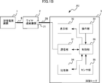
- FIG. 1A and 1B are views for explaining a welding system A1 according to the first embodiment.
- FIG. 1A is a schematic diagram showing the overall configuration of the welding system A1.
- FIG. 1B is a block diagram illustrating a functional configuration of the welding system A1.
- a welding system A1 includes a welding power source device 1, a wire feeding device 2, a welding torch 3, power cables 41 and 42, a power transmission line 5, a signal line 8, a gas cylinder 6, and a gas pipe. 7 is provided.
- One output terminal of the welding power source device 1 is connected to the welding torch 3 via the power cable 41.
- the wire feeding device 2 sends the wire electrode to the welding torch 3 so that the tip of the wire electrode protrudes from the tip of the welding torch 3.
- the power cable 41 and the wire electrode are electrically connected.
- the other output terminal of the welding power source apparatus 1 is connected to the workpiece W via the power cable 42.
- the welding power source device 1 generates an arc between the tip of the wire electrode protruding from the tip of the welding torch 3 and the workpiece W, and supplies electric power to the arc.
- the welding system A1 welds the workpiece W with the heat of the arc.
- the welding system A1 uses shield gas during welding.
- the shield gas of the gas cylinder 6 is supplied to the tip of the welding torch 3 by a gas pipe 7 provided so as to pass through the welding power supply device 1 and the wire feeding device 2.
- Electric power for example, DC 24 V
- Electric power for example, DC 24 V
- the welding power source device 1 and the wire feeding device 2 communicate with each other via a signal line 8.
- the welding system A1 may circulate cooling water through the welding torch 3.
- the welding power supply device 1 supplies electric power for arc welding to the welding torch 3.
- the welding power supply device 1 converts the three-phase AC power input from the power system P into power suitable for arc welding and outputs the power. Further, the welding power source device 1 converts the three-phase AC power input from the power system P into DC power for driving the feeding motor of the wire feeding device 2 and the like through the power transmission line 5. Output to the wire feeder 2.
- the welding power source device 1 is controlled to output electric power according to welding information, and the welding information is changed according to an operation of an operation unit (not shown).
- the welding power supply device 1 changes the welding information in accordance with a signal input from the welding torch 3 via the signal line 8.
- the wire feeding device 2 feeds the wire electrode to the welding torch 3.
- the wire electrode is guided to the tip of the welding torch 3 through the torch cable 39 and the inside of the liner provided inside the welding torch 3.
- the wire feeding device 2 drives a feeding motor or the like with power supplied from the welding power source device 1 through the power transmission line 5.
- the electric power is also supplied from the wire feeder 2 to the welding torch 3 via a power transmission line (not shown) provided in the torch cable 39.
- the wire feeding device 2 communicates with the welding power source device 1 through the signal line 8.
- the wire feeder 2 communicates with the welding torch 3 via a signal line (not shown) provided inside the torch cable 39.
- the welding torch 3 and the welding power source device 1 communicate with each other through the wire feeding device 2.
- the wire feeder 2 and the welding torch 3 are connected by a torch cable 39.
- the torch cable 39 is a cable connected to the base end of the welding torch 3, and a power cable 41, a gas pipe 7, a liner, a power transmission line, and a signal line are arranged inside the cable.
- the connector 21 is a connection terminal for connecting the welding torch 3 and the wire feeder 2.
- the connector 21 is a concave connection terminal, and a convex torch plug (not shown) provided at one end of the torch cable 39 of the welding torch 3 is inserted, so that the welding torch 3 and the wire feeding device are inserted. 2 is connected.
- the power cable 41, the gas pipe 7, the liner, the power transmission line 5 and the signal line 8 inside the wire feeder 2 are connected to the power cable 41 and the gas pipe 7 inside the torch cable 39, respectively. Connected to the liner, power transmission line and signal line.
- the welding torch 3 welds the workpiece W with the welding power supplied from the welding power source device 1.
- the welding torch 3 includes a communication unit 31, a display unit 32, an operation unit 33, a storage unit 34, a sensor unit 35, and a control unit 36 as functional blocks.
- the communication unit 31 is for communicating with the wire feeding device 2.
- the communication unit 31 transmits a signal input from the control unit 36 to the wire feeder 2 via a signal line inside the torch cable 39. Further, the communication unit 31 receives a signal input from the wire feeding device 2 via a signal line inside the torch cable 39 and outputs the signal to the control unit 36.
- a communication standard for example, CAN (Controller Area Network) is used.
- the display unit 32 performs various displays, and includes a display 321 (described later) which is a liquid crystal display device, for example.
- the display unit 32 is controlled by the control unit 36 and displays welding information stored in the storage unit 34.
- the operation unit 33 includes a plurality of operation means, and outputs the operation of each operation means by the operator to the control unit 36 as an operation signal.
- the operation means there are a torch switch 331 and an operation button 332 as described later.
- the operation unit 33 may be provided with other operation means.
- the storage unit 34 stores information such as each setting value of welding information and total welding time.
- the sensor unit 35 includes a plurality of sensors, and outputs a detection value of each sensor to the control unit 36.
- the sensor unit 35 includes an acceleration sensor 351 described later.
- the sensor unit 35 may include other sensors.
- the control unit 36 controls the welding torch 3 and is realized by, for example, a microcomputer.
- the control unit 36 performs predetermined processing in accordance with the operation signal input from the operation unit 33.
- the control unit 36 controls communication by the communication unit 31, writing and reading of information in the storage unit 34, and display on the display unit 32.
- the control part 36 performs a predetermined calculation based on the detection value input from the sensor part 35, and uses a calculation result for a process.
- the control unit 36 calculates the tilt information of the welding torch 3 based on the detection value detected by the acceleration sensor 351, and sets the welding information corresponding to the tilt information. Details of the welding information setting process corresponding to the tilt information will be described later.
- FIGS. 2A and 2B are views showing the appearance of an example of the welding torch 3.
- 2A is a front view and FIG. 2B is a plan view.
- the welding torch 3 includes a torch body 37, a handle 38, a control board 381, a torch switch 331, operation buttons 332, a display 321, an acceleration sensor 351, and a torch cable 39.
- the torch body 37 is a metal cylindrical member, in which a liner through which a welding cable is inserted, a power cable 41, and a gas pipe 7 are disposed.
- a nozzle 371 is attached to the tip of the torch body 37.
- the torch body 37 has a curved portion so that the operator can easily point the nozzle 371 toward the workpiece W.
- the handle 38 is a part for the operator to hold, and is provided so as to hold the base end portion of the torch body 37. An operator holds the handle 38 and performs a welding operation.
- the handle 38 is provided with a torch switch 331, an operation button 332, and a display 321.
- a control board 381 is arranged inside the handle 38. On the control board 381, circuits composing the communication unit 31, the display unit 32, the operation unit 33, the storage unit 34, the sensor unit 35, and the control unit 36 are mounted.
- the torch switch 331 is an operation means for accepting a start / stop operation of welding, and is arranged at a position where an operator who holds the handle 38 can easily perform a push operation with an index finger.
- an operation signal is output to the control unit 36, and the operation signal is input to the welding power source device 1, whereby the welding power source device 1 outputs welding power.
- the welding power source device 1 stops the output of the welding power by releasing the on operation. That is, welding is performed only while the torch switch 331 is pressed.
- the display 321 performs various displays, and is disposed on the opposite side of the handle 38 from the torch switch 331 so that an operator who holds the handle 38 and performs welding work can easily see the screen.
- the operation button 332 is an operation means for performing an operation for switching a screen or changing various setting values, and is disposed between the grip portion of the handle 38 and the display 321 on the same side as the display 321 of the handle 38. Yes.
- the operation button 332 includes an upper button 332a, a lower button 332b, a left button 332c, and a right button 332d.
- a corresponding operation signal is output to the control unit 36, and the control unit 36 performs a corresponding process.
- the left button 332c and the right button 332d are operation means for switching the screen displayed on the display 321.
- the upper button 332a and the lower button 332b are operation means for changing the set value displayed on the display 321.
- the display 321 is disposed on the same control board 381.
- the display screen of the display 321 has a predetermined angle with respect to the control board 381 so that the operator can easily operate each operation button 332 while looking at the display screen of the display 321. Yes.
- the display 321 may be arranged so that the display screen is parallel to the control board 381.
- a microcomputer as the control unit 36, a memory as the storage unit 34, a communication module as the communication unit 31, and various electronic components are also mounted.
- the acceleration sensor 351 is also mounted on the control board 381.
- the acceleration sensor 351 is a triaxial acceleration sensor, detects the acceleration in each axial direction, and outputs the detected value to the control unit 36.
- the control unit 36 calculates the tilt information of the welding torch 3 based on the detection value input from the acceleration sensor 351 of the sensor unit 35.
- the acceleration sensor 351 detects the acceleration in each axial direction of three axes that are set to be orthogonal to each other. Based on these accelerations, the control unit 36 calculates accelerations in the axial directions of three axes that are set in the welding torch 3 and are orthogonal to each other.
- an axis extending in the direction of the tip of the welding torch 3 (a central axis of the nozzle 371) is defined as one axis (hereinafter referred to as “z axis”).
- the control unit 36 determines an angle (hereinafter referred to as “the direction that the direction toward the distal end side of the welding torch 3 in the z-axis direction” and the downward direction in the vertical direction (the direction in which the gravitational acceleration works) from the calculated acceleration in each axial direction of the welding torch 3. "Torch tilt angle”) is calculated.
- the method for calculating the torch tilt angle by the control unit 36 is not limited.
- a part of the acceleration sensor 351 and the control unit 36 corresponds to an example of “sensor unit”, and “torch inclination angle” corresponds to an example of “inclination information”.
- the sensor unit 35 may include a gyro sensor instead of the acceleration sensor 351.
- the control unit 36 calculates the torch inclination angle from the angular velocity around each axis detected by the gyro sensor.
- the appearance of the welding torch 3 is not limited to that described above.
- the location and shape of the torch switch 331, the operation button 332, and the display 321 are not limited.
- the case where the operation button 332 is four independent buttons is shown, but one cross button may be used. Also, the number of buttons is not limited.
- welding is usually performed with the nozzle 371 of the welding torch 3 facing downward, but depending on the welding location, welding may be performed with the nozzle 371 facing upward.
- the output current is automatically changed according to the direction of the nozzle 371.
- the control unit 36 calculates the torch tilt angle based on the detection value input from the acceleration sensor 351.
- the torch inclination angle is an angle formed by the direction of the tip of the welding torch 3 (direction of the nozzle 371) and the lower side in the vertical direction, and indicates the angle of inclination of the tip of the welding torch 3 with respect to the lower side in the vertical direction.
- FIG. 3 is a diagram showing the relationship between the attitude of the welding torch 3 and the torch tilt angle.
- a dotted arrow indicates that the lower side in the vertical direction is the reference “0 °” and the upper side in the vertical direction is “180 °”.
- the welding torch 3a shows a state where the tip is directed downward in the vertical direction. In this case, since the direction of the tip of the welding torch 3a is the same as the downward direction in the vertical direction, the tilt angle of the torch is “0 °”.
- the welding torch 3b shows a state in which the tip is oriented in the horizontal direction. In this case, since the direction of the tip of the welding torch 3b is perpendicular to the vertical direction, the torch inclination angle is “90 °”.
- the welding torch 3c shows a state where the tip is directed upward in the vertical direction. In this case, since the direction of the tip of the welding torch 3c is opposite to the downward direction in the vertical direction, the torch inclination angle is “180 °”.
- the control unit 36 determines whether the torch inclination angle ⁇ belongs to any range of 0 ° ⁇ ⁇ ⁇ 45 °, 45 ° ⁇ ⁇ ⁇ 135 °, or 135 ° ⁇ ⁇ ⁇ 180 °. Change the welding current set value.
- the control unit 36 reads the welding current set value stored in the storage unit 34 and sets it as a reference current value. When the torch inclination angle ⁇ is 0 ° ⁇ ⁇ ⁇ 45 °, it is determined that the tip of the torch is facing downward, and the reference current value is set as the welding current set value.
- the torch inclination angle ⁇ is 45 ° ⁇ ⁇ ⁇ 135 °, it is determined that the tip of the torch is sideways, and a value obtained by subtracting the predetermined value ⁇ from the reference current value is set as the welding current setting value.
- the torch inclination angle ⁇ is 135 ° ⁇ ⁇ ⁇ 180 °, it is determined that the tip of the torch is upward, and a value obtained by subtracting the predetermined value ⁇ from the reference current value is set as the welding current setting value.
- the predetermined value ⁇ and the predetermined value ⁇ are set in advance according to the reference current value.
- the predetermined value ⁇ is set to 10 A
- the predetermined value ⁇ is set to 20 A. Therefore, when the torch inclination angle ⁇ is 0 ° ⁇ ⁇ ⁇ 45 °, the welding current set value is 150 A which is the reference current value, and when the torch inclination angle ⁇ is 45 ° ⁇ ⁇ ⁇ 135 °, the welding current set value is When the predetermined value ⁇ is subtracted from the reference current value 140A and the torch inclination angle ⁇ is 135 ° ⁇ ⁇ ⁇ 180 °, the welding current set value is 130A obtained by subtracting the predetermined value ⁇ from the reference current value.
- control unit 36 corresponds to an example of a “welding information acquisition unit”.
- the control unit 36 outputs the welding current set value to the communication unit 31 and transmits it to the welding power source device 1.
- the welding current set value transmitted from the communication unit 31 is received and set by the welding power source device 1.
- the welding power source device 1 controls the output current so as to be a set welding current set value. Thereby, the output current of the welding power source apparatus 1 is controlled to a current adapted to the direction of the nozzle 371.
- the control unit 36 does not cause the welding power source device 1 to transmit the welding current set value itself from the communication unit 31, but sets the welding current set value set in the welding power source device 1 by a predetermined value ⁇ (or ⁇ ). You may make it transmit the signal for decreasing.
- information on the torch tilt angle ⁇ is displayed on the display 321.
- the control unit 36 outputs the torch inclination angle ⁇ calculated by calculation to the display unit 32.
- the display unit 32 causes the display 321 to display information based on the input torch tilt angle ⁇ .
- the torch tilt angle ⁇ may be displayed as it is, or a torch picture may be displayed, and the displayed torch tilt may be changed according to the torch tilt angle ⁇ .
- the operator can know the torch tilt angle ⁇ by looking at the display 321 and can objectively recognize how much the welding torch 3 is tilted.
- the operator can switch the screen of the display 321 to display the currently set welding current set value, and can manually change the welding current set value.
- the screen displayed on the display 321 is switched by pressing the left button 332c or the right button 332d,
- the welding current set value can be increased (decreased) by displaying the “current setting” screen and pressing the upper button 332a (lower button 332b).
- a warning is displayed on the display 321 when the torch inclination angle ⁇ changes suddenly.
- the control unit 36 calculates the change amount ⁇ of the torch inclination angle ⁇ in a predetermined time, and the absolute value of the change amount ⁇ exceeds a predetermined value (when the torch inclination angle ⁇ suddenly changes). ), An instruction to display a warning on the display unit 32 is output.
- a warning is given when the angle changes by 5 ° or more per second, but the present invention is not limited to this.
- the control unit 36 corresponds to an example of a “change amount calculation unit”.
- the display unit 32 to which the instruction is input from the control unit 36 causes the display 321 to display a predetermined warning text (for example, “Please be careful about welding defects”).
- the display unit 32 corresponds to an example of a “notification unit”.
- the warning notification is not limited to display on the display 321.
- the warning may be notified by voice or buzzer sound. The operator can know by a warning that there is a possibility that a welding defect has occurred, and can recognize the welding defect.
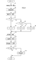
- FIG. 4 is a flowchart for explaining the welding information setting process performed by the control unit 36. This process is repeatedly executed at predetermined time intervals during welding work (while the torch switch 331 is pressed).
- the welding current set value is read from the storage unit 34 as the reference current value I (S1).
- acceleration information is detected (S2), and the torch inclination angle ⁇ is calculated (S3).
- the control unit 36 acquires the three-axis acceleration detection values detected by the acceleration sensor 351, and calculates the accelerations in the respective axial directions of the three axes set in the welding torch 3. Then, the torch inclination angle ⁇ is calculated from the calculated acceleration.
- the welding current set value I ′ is set based on the torch inclination angle ⁇ (S4 to S8).
- the torch inclination angle ⁇ is less than 45 ° (S4).
- the reference current value I is set as the welding current set value I ′ (S5).
- the torch inclination angle ⁇ is 45 ° or more (S4: NO)
- the welding current set value I ' is transmitted to the welding power source device 1 (S9).
- the control unit 36 outputs the welding current set value I ′ to the communication unit 31.
- the communication unit 31 transmits the welding current set value I ′ to the welding power source device 1.
- the welding power source apparatus 1 receives and sets the welding current set value I ′, and controls the output current to be the set welding current set value I ′. Thereby, the output current of the welding power source apparatus 1 is controlled to a current adapted to the torch inclination angle ⁇ .
- the control unit 36 outputs the torch inclination angle ⁇ to the display unit 32.
- the display unit 32 causes the display 321 to display information based on the input torch tilt angle ⁇ .
- a change amount ⁇ of the torch inclination angle ⁇ is calculated (S11). Specifically, the control unit 36 calculates the change amount ⁇ from the difference between the torch inclination angle ⁇ calculated this time and the previously calculated torch inclination angle ⁇ . Then, the absolute value of the change amount [Delta] [theta] is equal to or less than a predetermined value [Delta] [theta] 0 is determined (S12). If the absolute value of the change amount ⁇ is equal to or smaller than the predetermined value ⁇ 0 (S12: YES), the process is terminated.
- the control unit 36 outputs an instruction to display a warning on the display unit 32.
- the display unit 32 that has received the instruction displays a predetermined warning text on the display 321.
- the process illustrated in the flowchart of FIG. 4 is an example, and the welding information setting process performed by the control unit 36 is not limited to the above-described process.
- the process of calculating and determining the change amount ⁇ (S11 to S13) is executed at a timing (for example, when S1 to S10 are performed a predetermined number of times) different from the process (S1 to S10) of setting the welding information. You may do it.
- the control unit 36 calculates the torch inclination angle ⁇ based on the detection value input from the acceleration sensor 351, and changes the welding current set value according to the calculated torch inclination angle ⁇ (not changed). Including cases).
- the welding current set value is transmitted via the communication unit 31 and set in the welding power source apparatus 1.
- the welding power source device 1 controls the output current so as to be a set welding current set value.
- the output current of the welding power source apparatus 1 is controlled to a current adapted to the direction of the nozzle 371. Therefore, the operator can change the current to be adapted to the direction of the nozzle 371 without operating the operation button 332 of the welding torch 3. Since it is not necessary to operate the operation button 332 of the welding torch 3, it is possible to prevent a welding defect from being generated due to camera shake caused by the operation.
- information on the torch tilt angle ⁇ is displayed on the display 321.
- the operator can know the torch inclination angle ⁇ by looking at the display 321 and can objectively recognize how much the welding torch 3 is inclined.
- the operator can manually change the welding current set value if he / she wants to increase (decrease) the current a little more, judging from the welding state and the torch inclination angle ⁇ .
- the control unit 36 calculates the change amount ⁇ of the torch inclination angle ⁇ , and when the absolute value of the change amount ⁇ exceeds the predetermined value ⁇ 0 (the torch inclination angle ⁇ has changed suddenly). A warning is displayed on the display unit 32. Thereby, the operator can know by a warning that the welding defect may have occurred, and can recognize the welding defect.
- the welding current set value is changed based on the torch inclination angle ⁇ calculated by the control unit 36 from the detection value detected by the acceleration sensor 351, but the present invention is not limited to this.
- the welding current set value may be changed based on the acceleration detected by the acceleration sensor 351.
- the acceleration sensor 351 corresponds to an example of “sensor unit”
- the acceleration in each axial direction detected by the acceleration sensor 351 corresponds to an example of “tilt information”.
- the torch inclination angle ⁇ is an angle formed by the direction of the tip of the welding torch 3 and the lower side in the vertical direction is described, but is not limited thereto.
- the torch inclination angle ⁇ may be an angle formed by the direction of the tip of the welding torch 3 and the upper side in the vertical direction.
- the welding current set value may be decreased as the torch inclination angle ⁇ is decreased.
- the torch inclination angle ⁇ may be an angle formed by a direction based on gravity and a direction for indicating the attitude of the welding torch 3. Since the welding current set value is changed depending on which direction the tip of the welding torch 3 is directed with respect to the direction of gravity, the angle between the tip direction of the welding torch 3 and the vertical downward direction is the torch inclination.
- the angle ⁇ is desirable.
- the torch inclination angle ⁇ is in any range of 0 ° ⁇ ⁇ ⁇ 45 ° (downward), 45 ° ⁇ ⁇ ⁇ 135 ° (horizontal), and 135 ° ⁇ ⁇ ⁇ 180 ° (upward).
- each range may be appropriately set such that 0 ° ⁇ ⁇ ⁇ 60 ° (downward), 60 ° ⁇ ⁇ ⁇ 145 ° (horizontal), and 145 ° ⁇ ⁇ ⁇ 180 °.
- the welding current set value remains as a value obtained by subtracting the predetermined value ⁇ from the reference current value, and when entering the downward range from the hysteresis region, Change the welding current set value to the reference current value.
- frequent switching of the welding current set value due to the torch inclination angle ⁇ being frequently raised and lowered at the boundary of each range can be prevented.
- the range division for determining the torch inclination angle ⁇ is three ranges, but is not limited to this, and may be two ranges or four or more ranges.
- five ranges of 0 ° ⁇ ⁇ ⁇ 30 °, 30 ° ⁇ ⁇ ⁇ 60 °, 60 ° ⁇ ⁇ ⁇ 120 °, 120 ° ⁇ ⁇ ⁇ 150 °, and 150 ° ⁇ ⁇ ⁇ 180 ° may be used.
- the welding current set value can be switched in five stages.
- the welding current set value may be linearly changed according to the torch inclination angle ⁇ .
- I ′ I ⁇ a ⁇ ⁇ (1)
- the welding current set value is changed based on the torch inclination angle ⁇
- the welding voltage set value may be changed instead of the welding current set value.
- the welding voltage set value may be set to be smaller as the torch inclination angle ⁇ is larger.
- the rate of change in the current rise at the time of a short circuit may be changed.
- the rising change speed may be set to be smaller as the torch inclination angle ⁇ is larger.
- a plurality of pieces of welding information may be changed.
- the values of each welding information with respect to the torch inclination angle ⁇ may be stored in the storage unit 34 as a table.
- FIG. 5A shows an output current waveform when the peak current set value is changed according to the torch inclination angle ⁇ .
- the broken-line waveform shown in the figure has a torch inclination angle ⁇ of 0 ° ⁇ ⁇ ⁇ 45 ° (downward), and the dashed-dotted waveform has a torch inclination angle ⁇ of 45 ° ⁇ ⁇ ⁇ 135 ° (horizontal).
- the current setting value (base current setting value) at a low level of the pulse may be set to be smaller as the torch inclination angle ⁇ is larger.
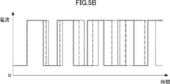
- FIG. 5B shows an output current waveform when the high level period is changed according to the torch inclination angle ⁇ .
- the broken-line waveform shown in the figure has a torch inclination angle ⁇ of 0 ° ⁇ ⁇ ⁇ 45 ° (downward), and the dashed-dotted waveform has a torch inclination angle ⁇ of 45 ° ⁇ ⁇ ⁇ 135 ° (horizontal).
- the pulse low level period may be set longer as the torch tilt angle ⁇ is larger.
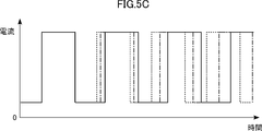
- 5C shows an output current waveform when the low level period is changed according to the torch inclination angle ⁇ .
- the broken-line waveform shown in the figure has a torch inclination angle ⁇ of 0 ° ⁇ ⁇ ⁇ 45 ° (downward), and the dashed-dotted waveform has a torch inclination angle ⁇ of 45 ° ⁇ ⁇ ⁇ 135 ° (horizontal).
- FIG. 6A shows an output current waveform when the pulse frequency is changed according to the torch inclination angle ⁇ .
- the broken-line waveform shown in the figure has a torch inclination angle ⁇ of 0 ° ⁇ ⁇ ⁇ 45 ° (downward), and the dashed-dotted waveform has a torch inclination angle ⁇ of 45 ° ⁇ ⁇ ⁇ 135 ° (horizontal).
- the duty ratio of the pulse may be set to be smaller as the torch inclination angle ⁇ is larger.
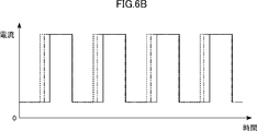
- FIG. 6B shows an output current waveform when the duty ratio of the pulse is changed according to the torch inclination angle ⁇ .
- the broken-line waveform shown in the figure has a torch inclination angle ⁇ of 0 ° ⁇ ⁇ ⁇ 45 ° (downward), and the dashed-dotted waveform has a torch inclination angle ⁇ of 45 ° ⁇ ⁇ ⁇ 135 ° (horizontal).
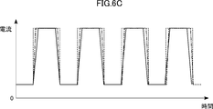
- FIG. 6C shows an output current waveform when the rising and falling slopes of the pulse are changed according to the torch inclination angle ⁇ .
- the broken-line waveform shown in the figure has a torch inclination angle ⁇ of 0 ° ⁇ ⁇ ⁇ 45 ° (downward), and the dashed-dotted waveform has a torch inclination angle ⁇ of 45 ° ⁇ ⁇ ⁇ 135 ° (horizontal).
- FIG. 7A is a diagram illustrating an example of a table.
- the torch inclination angle ⁇ is 0 ° ⁇ ⁇ ⁇ 45 ° (downward)
- the base current and the low level period are not changed (condition 1)
- the torch inclination angle ⁇ is 45 ° ⁇ ⁇ ⁇ .
- FIG. 7B shows an output current waveform when the base current set value and the low level period are changed according to the torch inclination angle ⁇ and the table shown in FIG. 7A.
- the broken-line waveform shown in the figure has a torch inclination angle ⁇ of 0 ° ⁇ ⁇ ⁇ 45 ° (downward), and the dashed-dotted waveform has a torch inclination angle ⁇ of 45 ° ⁇ ⁇ ⁇ 135 ° (horizontal).
- the larger the torch inclination angle ⁇ the smaller the difference between the base current and the peak current and the longer the low level period, thereby reducing the amount of power supplied.
- the output of the welding power source apparatus 1 may be an alternating current output.
- the AC frequency may be set higher as the torch inclination angle ⁇ is larger.
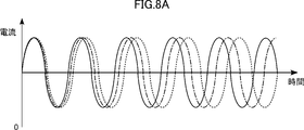
- FIG. 8A shows an output current waveform when the AC frequency is changed according to the torch inclination angle ⁇ .
- the broken-line waveform shown in the figure has a torch inclination angle ⁇ of 0 ° ⁇ ⁇ ⁇ 45 ° (downward), and the dashed-dotted waveform has a torch inclination angle ⁇ of 45 ° ⁇ ⁇ ⁇ 135 ° (horizontal).
- the welding power source device 1 is an alternating current output
- a state in which the welding torch 3 is positive and the workpiece W is negative and a current is supplied and a state in which the welding torch 3 is negative and the workpiece W is positive and a current is supplied are as follows: Repeated alternately.
- the ratio of the time which makes the welding torch 3 positive is adjusted.
- the offset value x is adjusted in the following equation (2) indicating the control target Iref of the output alternating current of the welding power source apparatus 1.
- A is the amplitude
- ⁇ is the angular frequency
- ⁇ is the initial phase.
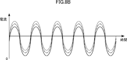
- FIG. 8B shows an output current waveform when the ratio of time for making the welding torch 3 positive is changed according to the torch inclination angle ⁇ .
- the broken-line waveform shown in the figure has a torch inclination angle ⁇ of 0 ° ⁇ ⁇ ⁇ 45 ° (downward), and the dashed-dotted waveform has a torch inclination angle ⁇ of 45 ° ⁇ ⁇ ⁇ 135 ° (horizontal).
- the parameters of the welding information to be changed according to the torch inclination angle ⁇ are not limited to those described above.
- the present invention is not limited to this.
- communication may be performed by superimposing a signal on the power cables 41 and 42 or the power transmission line 5.
- the signal line 8 that connects the welding power supply device 1 and the wire feeding device 2 is required. do not do.
- FIG. 9 is a block diagram showing a functional configuration of the welding system A2 according to the second embodiment.
- the welding system A2 shown in FIG. 9 is different from the welding system A1 according to the first embodiment in that the welding torch 3 performs wireless communication with the welding power source device 1.
- the communication unit 31 transmits and receives signals via an antenna.
- the communication unit 31 modulates a signal input from the control unit 36 and transmits it as an electromagnetic wave. Further, the communication unit 31 demodulates the electromagnetic wave received by the antenna and outputs the demodulated signal to the control unit 36.
- the communication unit 31 performs wireless communication with the communication unit 11 of the welding power source device 1.
- FIG. 10 is a block diagram showing a functional configuration of the welding system A3 according to the third embodiment.
- a welding system A3 shown in FIG. 10 is different from the welding system A1 according to the first embodiment in that the wire feeding device 2 is not provided.
- the welding system A3 is a non-consumable electrode type welding system that does not use a wire electrode.
- the welding power supply device 1 and the welding torch 3 are connected by a torch cable 39.
- the welding power supply device 1 includes a connector 12 that is, for example, a concave connection terminal.
- the connector 12 connects the welding torch 3 and the welding power source device 1 by inserting a convex torch plug (not shown) provided at one end of the torch cable 39 of the welding torch 3.
- a convex torch plug (not shown) provided at one end of the torch cable 39 of the welding torch 3.
- the power cable 41, the gas pipe 7, the power transmission line 5 and the signal line 8 inside the welding power source apparatus 1 are connected to the power cable 41, the gas pipe 7 and the power transmission inside the torch cable 39, respectively. Connected to lines and signal lines.
- the welding torch and the welding system according to the present disclosure are not limited to the above-described embodiment.
- the specific configuration of each part of the welding torch and the welding system according to the present disclosure can be varied in design in various ways.
- the above embodiment includes configurations according to the following supplementary notes.
- Appendix 1 A welding torch that is supplied with electric power from a welding power source device and performs arc welding, A sensor unit for detecting inclination information of the welding torch; A welding information acquisition unit that acquires welding information adapted to the inclination information detected by the sensor unit; A welding torch comprising: a communication unit that transmits the welding information acquired by the welding information acquisition unit to the welding power source device.
- the sensor unit detects an angle formed by a direction of a tip of the welding torch and a vertically lower portion as the inclination information; The welding torch according to appendix 1.
- the welding information acquisition unit determines which range of the plurality of ranges the inclination information belongs to, and acquires the welding information based on a value associated with the determined range.
- the number of the plurality of ranges is three.
- the boundary region of the plurality of ranges is provided with a region having hysteresis characteristics.
- the welding information acquisition unit acquires the welding information based on a value that linearly changes according to the tilt information.
- the welding information is a welding current setting value.
- the welding power supply device outputs a pulsed current,
- the welding information is Pulse base current setting value, Pulse peak current setting value, The low level period of the pulse, The high-level period of the pulse, The frequency of the pulse, Pulse duty ratio, and The slope of the rise or fall of the pulse, Containing any of the The welding torch according to any one of appendices 1 to 6.
- the welding power supply device outputs an alternating current,
- the welding information is AC frequency, or The percentage of time to make the welding torch plus, Including, The welding torch according to any one of appendices 1 to 6.
- [Appendix 10] A display unit for displaying the tilt information; The welding torch according to any one of appendices 1 to 9.
- [Appendix 11] A change amount calculation unit for calculating a change amount of the inclination information; A notification unit that notifies a warning when the change amount calculated by the change amount calculation unit exceeds a predetermined value; The welding torch according to any one of appendices 1 to 10.
- [Appendix 12] The welding torch according to any one of appendices 1 to 11, wherein the sensor unit includes an acceleration sensor.
- [Appendix 13] The welding torch according to any one of appendices 1 to 12, The welding power source;
- a welding system comprising:
Landscapes
- Engineering & Computer Science (AREA)
- Physics & Mathematics (AREA)
- Plasma & Fusion (AREA)
- Mechanical Engineering (AREA)
- Theoretical Computer Science (AREA)
- Arc Welding Control (AREA)
- Arc Welding In General (AREA)
Abstract
本開示の一側面によると、溶接電源装置から電力を供給されてアーク溶接を行う溶接トーチが提供される。前記溶接トーチは、前記溶接トーチの傾き情報を検出するセンサ部と、前記センサ部が検出した前記傾き情報に適応した溶接情報を取得する溶接情報取得部と、前記溶接情報取得部が取得した前記溶接情報を前記溶接電源装置に送信する通信部と、を備える。
Description
本開示は、溶接トーチおよび溶接システムに関する。
消耗電極式の溶接システムは、通常、重量があるために移動させない溶接電源装置と、溶接個所の変更に伴って溶接作業者が持ち運びするワイヤ送給装置および溶接トーチとに分離されている。溶接電源装置が溶接作業を行っている位置から離れた場所に設置されている場合、溶接電流などの溶接情報を設定するために、作業者が溶接電源装置の設置場所まで行くのは作業効率が悪い。これを解消するために、溶接トーチに操作ボタンを配置して、当該操作ボタンの操作によって溶接情報を設定できる溶接トーチが開発されている。
アーク溶接において、通常は溶接トーチの先端を下方に向けて溶接を行うが、溶接個所に応じて、先端を上方に向けて溶接を行う場合がある。この場合、先端を下方に向けているときよりも溶接電流を低下させた方が溶接痕を美しく仕上げることができる。溶接個所に沿って、溶接トーチの先端を下方から水平方向や上方に変化させながら連続して溶接を行う場合、溶接の途中で溶接電流を変化させる必要があることがある。従来の溶接トーチの場合、溶接を行いながら、手元の操作ボタンの操作により溶接電流設定値を変更することができる。
しかしながら、溶接を行いながら操作ボタンを操作すると、手振れにより溶接欠陥が発生する場合がある。
本開示は上記した事情のもとで考え出されたものであって、溶接欠陥の発生を抑制することができる溶接トーチ、および、当該溶接トーチを備えた溶接システムを提供することをその目的としている。
本開示の第1の側面によって提供される溶接トーチは、溶接電源装置から電力を供給されてアーク溶接を行う溶接トーチであって、前記溶接トーチの傾き情報を検出するセンサ部と、前記センサ部が検出した前記傾き情報に適応した溶接情報を取得する溶接情報取得部と、前記溶接情報取得部が取得した前記溶接情報を前記溶接電源装置に送信する通信部とを備えていることを特徴とする。
「傾き情報」とは、溶接トーチの傾きの度合いを示す情報であって、例えば鉛直方向などの基準の方向に対して、溶接トーチ内の所定の軸の向きがどの程度傾いているかを示す角度などである。「溶接情報」とは、溶接電源装置が出力する溶接電力を制御するためのパラメータ値である。例えば、溶接電源装置が直流出力を行う場合は、溶接電流設定値、溶接電圧設定値、短絡時の電流の立上り変化速度などが溶接情報に相当する。また、溶接電源装置がパルス出力を行う場合は、パルスのベース電流設定値、ピーク電流設定値、ローレベル期間、ハイレベル期間、パルス周波数、パルスのデューティ比、パルスの立上りおよび立下りの傾斜などが溶接情報に相当し、溶接電源装置が交流出力を行う場合は、交流周波数、溶接トーチをプラスにする時間の割合などが溶接情報に相当する。
本実施形態の構成によると、溶接欠陥が発生することを防止できる。
本開示の好ましい実施の形態においては、前記センサ部は、前記溶接トーチの先端の向きと鉛直方向下方とがなす角度を前記傾き情報として検出する。この構成によると、鉛直方向下方を基準とした溶接トーチの先端の向きを傾き情報として検出することができる。これにより、溶接トーチの先端の客観的な向きを検出することができる。
本開示の好ましい実施の形態においては、前記溶接情報取得部は、前記傾き情報が複数の範囲のどの範囲に属するかを判別し、判別した範囲に対応付けられた値に基づいて前記溶接情報を取得する。この構成によると、傾き情報に対応する溶接情報を容易に取得することができる。
本開示の好ましい実施の形態においては、前記範囲は3つの範囲に分けられている。この構成によると、溶接トーチの傾き方が3つの向きのいずれであるか(例えば、溶接トーチの先端が下を向いているか、横を向いているか、上を向いているか)を判断することができる。
本開示の好ましい実施の形態においては、前記複数の範囲の境界領域には、ヒステリシス特性を有する領域が設けられている。この構成によると、傾き情報が各範囲の境界で頻繁に上下することによる溶接情報の頻繁な切り替えを防ぐことができる。
本開示の好ましい実施の形態においては、前記溶接情報取得部は、前記傾き情報に応じて線形的に変化する値に基づいて前記溶接情報を取得する。この構成によると、傾き情報が変化したときに、溶接情報が大きく変化することを抑制できる。
本開示の好ましい実施の形態においては、前記溶接情報は溶接電流設定値である。この構成によると、傾き情報に適応した溶接電流設定値を溶接電源装置に送信することができる。これにより、溶接電源装置は、受信した溶接電流設定値を設定することで、溶接トーチの状態に適応した出力を行うことができる。
本開示の好ましい実施の形態においては、前記溶接電源装置はパルス状の電流を出力し、前記溶接情報は、パルスのベース電流設定値、ピーク電流設定値、ローレベル期間、ハイレベル期間、パルス周波数、パルスのデューティ比、および、パルスの立上りあるいは立下りの傾斜のいずれかを含んでいる。この構成によると、傾き情報に適応したこれらの溶接情報を溶接電源装置に送信することができる。これにより、溶接電源装置は、受信した溶接情報を設定することで、溶接トーチの状態に適応した出力を行うことができる。
本開示の好ましい実施の形態においては、前記溶接電源装置は交流電流を出力し、前記溶接情報は、交流周波数、または、前記溶接トーチをプラスにする時間の割合を含んでいる。この構成によると、傾き情報に適応したこれらの溶接情報を溶接電源装置に送信することができる。これにより、溶接電源装置は、受信した溶接情報を設定することで、溶接トーチの状態に適応した出力を行うことができる。
本開示の好ましい実施の形態においては、前記傾き情報に関する表示を行う表示部をさらに備えている。この構成によると、作業者は、表示部の表示を見ることで、溶接トーチをどの程度傾けているかを客観的に認識することができる。
本開示の好ましい実施の形態においては、前記傾き情報の変化量を演算する変化量演算部と、前記変化量演算部が算出した変化量が所定値を超えた場合に警告を報知する報知部と、をさらに備えている。この構成によると、傾き情報に急激な変化が生じた場合に警告を報知することができる。これにより、作業者は、傾き情報に急激な変化が生じたことを知ることができる。
本開示の好ましい実施の形態においては、前記センサ部は、加速度センサを備えている。この構成によると、検出された加速度に基づいて、傾き情報を検出することができる。
本開示の第2の側面によって提供される溶接システムは、本開示の第1の側面によって提供される溶接トーチと、前記溶接電源装置とを備える。
本開示のその他の特徴および利点は、添付図面を参照して以下に行う詳細な説明によって、より明らかとなろう。
以下、本開示の実施の形態を、本開示を溶接トーチ(溶接システム)に適用した場合を例として、図面を参照して具体的に説明する。
図1A,1Bは、第1実施形態に係る溶接システムA1を説明するための図である。図1Aは、溶接システムA1の全体構成を示す概要図である。図1Bは、溶接システムA1の機能構成を示すブロック図である。
図1A,1Bに示すように、溶接システムA1は、溶接電源装置1、ワイヤ送給装置2、溶接トーチ3、パワーケーブル41,42、電力伝送線5、信号線8、ガスボンベ6、およびガス配管7を備えている。溶接電源装置1の一方の出力端子は、パワーケーブル41を介して、溶接トーチ3に接続されている。ワイヤ送給装置2は、ワイヤ電極を溶接トーチ3に送り出して、ワイヤ電極の先端を溶接トーチ3の先端から突出させる。溶接トーチ3の先端に配置されているコンタクトチップにおいて、パワーケーブル41とワイヤ電極とは電気的に接続されている。溶接電源装置1の他方の出力端子は、パワーケーブル42を介して、被加工物Wに接続される。溶接電源装置1は、溶接トーチ3の先端から突出するワイヤ電極の先端と、被加工物Wとの間にアークを発生させ、アークに電力を供給する。溶接システムA1は、当該アークの熱で被加工物Wの溶接を行う。
溶接システムA1は、溶接時にシールドガスを用いる。ガスボンベ6のシールドガスは、溶接電源装置1およびワイヤ送給装置2を通るように設けられているガス配管7によって、溶接トーチ3の先端に供給される。溶接電源装置1からワイヤ送給装置2へは、送給モータなどを駆動させるための電力(例えばDC24V)が、電力伝送線5を介して供給される。また、溶接電源装置1とワイヤ送給装置2とは、信号線8を介して通信を行っている。なお、溶接システムA1は、溶接トーチ3に冷却水を循環させるようになっていてもよい。
溶接電源装置1は、アーク溶接のための電力を溶接トーチ3に供給するものである。溶接電源装置1は、電力系統Pから入力される三相交流電力をアーク溶接に適した電力に変換して出力する。また、溶接電源装置1は、電力系統Pから入力される三相交流電力を、ワイヤ送給装置2の送給モータなどを駆動するための直流電力に変換して、電力伝送線5を介してワイヤ送給装置2に出力する。
溶接電源装置1は、溶接情報に応じて電力を出力するように制御されており、溶接情報は、図示しない操作部の操作に応じて変更される。また、溶接電源装置1は、信号線8を介して溶接トーチ3から入力される信号に応じて、溶接情報を変更する。
ワイヤ送給装置2は、ワイヤ電極を溶接トーチ3に送り出すものである。ワイヤ電極は、トーチケーブル39および溶接トーチ3の内部に設けられているライナの内部を通って、溶接トーチ3の先端に導かれる。ワイヤ送給装置2は、電力伝送線5を介して溶接電源装置1から供給される電力で、送給モータなどを駆動させる。また、この電力は、ワイヤ送給装置2からトーチケーブル39内部に設けられている電力伝送線(図示なし)を介して、溶接トーチ3にも供給される。ワイヤ送給装置2は、信号線8を介して、溶接電源装置1と通信を行う。また、ワイヤ送給装置2は、トーチケーブル39内部に設けられている信号線(図示なし)を介して、溶接トーチ3と通信を行う。溶接トーチ3と溶接電源装置1とは、ワイヤ送給装置2を仲介することで、通信を行う。
ワイヤ送給装置2と溶接トーチ3とは、トーチケーブル39によって接続されている。トーチケーブル39は、溶接トーチ3の基端に接続されたケーブルであり、ケーブル内部にパワーケーブル41、ガス配管7、ライナ、電力伝送線および信号線が配置されている。
コネクタ21は、溶接トーチ3とワイヤ送給装置2とを接続するための接続用端子である。例えば、コネクタ21は、凹型の接続用端子であり、溶接トーチ3のトーチケーブル39の一端に備えられた凸型のトーチプラグ(図示しない)を差し込まれることで、溶接トーチ3とワイヤ送給装置2とを接続する。このコネクタ21を介して、ワイヤ送給装置2の内部のパワーケーブル41、ガス配管7、ライナ、電力伝送線5および信号線8が、それぞれ、トーチケーブル39の内部のパワーケーブル41、ガス配管7、ライナ、電力伝送線および信号線に接続される。
溶接トーチ3は、溶接電源装置1から供給される溶接電力により、被加工物Wの溶接を行う。溶接トーチ3は、機能ブロックとして、通信部31、表示部32、操作部33、記憶部34、センサ部35、および制御部36を備えている。
通信部31は、ワイヤ送給装置2との間で通信を行うためのものである。通信部31は、制御部36から入力される信号を、トーチケーブル39内部の信号線を介して、ワイヤ送給装置2に送信する。また、通信部31は、トーチケーブル39内部の信号線を介してワイヤ送給装置2から入力される信号を受信して、制御部36に出力する。通信の規格としては、例えばCAN(Controller Area Network)が使用される。
表示部32は、各種表示を行うものであり、例えば液晶表示装置であるディスプレイ321(後述)を備えている。表示部32は、制御部36によって制御されており、記憶部34に記憶されている溶接情報の表示を行う。
操作部33は、複数の操作手段を備えており、作業者による各操作手段の操作を操作信号として制御部36に出力するものである。操作手段としては、後述するように、トーチスイッチ331および操作ボタン332がある。なお、操作部33には、他の操作手段が設けられていてもよい。
記憶部34は、溶接情報の各設定値や、総溶接時間などの情報を記憶するものである。
センサ部35は、複数のセンサを備えており、各センサの検出値を制御部36に出力する。本実施形態において、センサ部35は、後述する加速度センサ351を備えている。なお、センサ部35は、その他のセンサを備えていてもよい。
制御部36は、溶接トーチ3の制御を行うものであり、例えばマイクロコンピュータなどによって実現されている。制御部36は、操作部33より入力される操作信号に応じて、所定の処理を行う。また、制御部36は、通信部31による通信や、記憶部34の情報の書き込みおよび読出し、表示部32での表示を制御する。また、制御部36は、センサ部35より入力される検出値に基づいて、所定の演算を行い、演算結果を処理に用いる。具体的には、制御部36は、加速度センサ351が検出した検出値に基づいて溶接トーチ3の傾き情報を演算し、傾き情報に対応した溶接情報の設定を行う。傾き情報に対応した溶接情報の設定処理の詳細については後述する。
図2A,Bは、溶接トーチ3の一例の外観を示す図である。図2Aは正面図であり、図2Bは平面図である。図2A,Bに示すように、溶接トーチ3は、トーチボディ37、ハンドル38、制御基板381、トーチスイッチ331、操作ボタン332、ディスプレイ321、加速度センサ351、およびトーチケーブル39を備えている。
トーチボディ37は、金属製の筒状の部材であり、内部に、溶接ケーブルが挿通されたライナ、パワーケーブル41、およびガス配管7が配置されている。トーチボディ37の先端には、ノズル371が取り付けられている。トーチボディ37は、作業者が被加工物Wに対してノズル371を向けやすいように、湾曲部分を有している。
ハンドル38は、作業者が把持するための部位であり、トーチボディ37の基端部を保持するように設けられている。作業者は、このハンドル38を把持して、溶接作業を行う。ハンドル38には、トーチスイッチ331、操作ボタン332、およびディスプレイ321が配置されている。また、ハンドル38の内部には、制御基板381が配置されている。制御基板381には、通信部31、表示部32、操作部33、記憶部34、センサ部35、および制御部36を構成する回路が搭載されている。
トーチスイッチ331は、溶接の開始/停止操作を受け付けるための操作手段であり、ハンドル38を把持した作業者が、人差し指で押動操作しやすい位置に配置されている。トーチスイッチ331のオン操作(押下)により、操作信号が制御部36に出力され、当該操作信号が溶接電源装置1に入力されることで、溶接電源装置1は溶接電力の出力を行う。オン操作が解除されることで、溶接電源装置1は、溶接電力の出力を停止する。すなわち、トーチスイッチ331を押下している間だけ溶接が行われる。
ディスプレイ321は、各種表示を行うものであり、ハンドル38を把持して溶接作業を行う作業者が画面を見やすいように、ハンドル38のトーチスイッチ331とは反対側に配置されている。
操作ボタン332は、画面の切り替えや各種設定値を変更する操作を行うための操作手段であり、ハンドル38のディスプレイ321と同じ側の、ハンドル38の把持部分とディスプレイ321との間に配置されている。操作ボタン332は、上ボタン332a、下ボタン332b、左ボタン332c、および右ボタン332dからなる。各ボタン332a~332dが押下されると、対応する操作信号が制御部36に出力され、制御部36は対応する処理を行う。左ボタン332cおよび右ボタン332dは、ディスプレイ321に表示される画面を切り替えるための操作手段である。上ボタン332aおよび下ボタン332bは、ディスプレイ321に表示されている設定値を変更するための操作手段である。
各操作ボタン332の押下を検知するセンサは、制御基板381に搭載されている。また、ディスプレイ321は、同じ制御基板381上に配置されている。本実施形態においては、作業者がディスプレイ321の表示画面を見ながら各操作ボタン332の操作を行いやすいように、ディスプレイ321の表示画面が制御基板381に対して所定の角度を有するようになっている。なお、ディスプレイ321は、表示画面が制御基板381と平行になるように配置されていてもよい。制御基板381には、制御部36としてのマイクロコンピュータ、記憶部34としてのメモリ、通信部31としての通信モジュール、および各種電子部品も搭載されている。加速度センサ351も制御基板381上に搭載されている。
加速度センサ351は、3軸の加速度センサであり、各軸方向の加速度を検出して、検出値を制御部36に出力する。制御部36は、センサ部35の加速度センサ351より入力される検出値に基づいて、溶接トーチ3の傾き情報を演算する。加速度センサ351は、自身に設定されている互いに直交する3つの軸の各軸方向の加速度を検出する。制御部36は、これらの加速度に基づいて、溶接トーチ3に設定された、互いに直交する3つの軸の各軸方向の加速度を演算する。本実施形態では、溶接トーチ3の先端の向きに延びる軸(ノズル371の中心軸)を1つの軸(以下では「z軸」とする)としている。制御部36は、演算した溶接トーチ3の各軸方向の加速度から、z軸方向の溶接トーチ3の先端側に向かう向きと鉛直方向下方(重力加速度の働く向き)とがなす角度(以下では、「トーチ傾き角」とする)を演算する。なお、制御部36によるトーチ傾き角の演算方法は限定されない。本実施形態においては、加速度センサ351および制御部36の一部が「センサ部」の一例に相当し、「トーチ傾き角」が「傾き情報」の一例に相当する。なお、センサ部35は、加速度センサ351に代えて、ジャイロセンサを備えていてもよい。この場合、制御部36は、ジャイロセンサが検出した各軸周りの角速度からトーチ傾き角を演算する。
なお、溶接トーチ3の外観は上述したものに限定されない。例えば、トーチスイッチ331、操作ボタン332、およびディスプレイ321の配置場所や形状は限定されない。また、本実施形態においては、操作ボタン332が4つの独立したボタンである場合を示したが、1つの十字ボタンであってもよい。また、ボタンの数も限定されない。
次に、傾き情報に対応した溶接情報の設定処理について説明する。
アーク溶接において、通常は溶接トーチ3のノズル371を下方に向けて溶接を行うが、溶接個所に応じて、ノズル371を上方に向けて溶接を行う場合がある。この場合、溶接痕を美しく仕上げるためには、ノズル371を下方に向けているときよりも、出力電流を低下させて、ノズル371の向きに適応した出力電流とする必要がある。本実施形態では、ノズル371の向きに適応させて、自動的に出力電流を変化させる。
制御部36は、加速度センサ351より入力される検出値に基づいて、トーチ傾き角を演算する。トーチ傾き角は、溶接トーチ3の先端の向き(ノズル371の向き)と鉛直方向下方とがなす角度であり、鉛直方向下方を基準とした溶接トーチ3の先端の傾きの角度を示している。
図3は、溶接トーチ3の姿勢とトーチ傾き角の関係を示す図である。同図においては、鉛直方向下方を基準の「0°」とし、鉛直方向上方を「180°」としていることを破線矢印で示している。溶接トーチ3aは、先端が鉛直方向下方を向いている状態を示している。この場合は、溶接トーチ3aの先端の向きが鉛直方向下方と同じ向きになっているので、トーチ傾き角は「0°」となる。溶接トーチ3bは、先端が水平方向を向いている状態を示している。この場合は、溶接トーチ3bの先端の向きが鉛直方向に対して直交する向きになっているので、トーチ傾き角は「90°」となる。溶接トーチ3cは、先端が鉛直方向上方を向いている状態を示している。この場合は、溶接トーチ3cの先端の向きが鉛直方向下方に対して正反対の向きになっているので、トーチ傾き角は「180°」となる。
本実施形態では、制御部36は、トーチ傾き角θが、0°≦θ<45°、45°≦θ<135°、135°≦θ≦180°のうちのいずれの範囲に属するかによって、溶接電流設定値を変更する。制御部36は、記憶部34に記憶されている溶接電流設定値を読み出してこれを基準電流値とする。そして、トーチ傾き角θが0°≦θ<45°の場合は、トーチの先端が下向きであると判断して、基準電流値を溶接電流設定値とする。また、トーチ傾き角θが45°≦θ<135°の場合は、トーチの先端が横向きであると判断して、基準電流値から所定値αを減算した値を溶接電流設定値とする。また、トーチ傾き角θが135°≦θ≦180°の場合は、トーチの先端が上向きであると判断して、基準電流値から所定値βを減算した値を溶接電流設定値とする。所定値αおよび所定値βは、基準電流値に応じてあらかじめ設定されている。例えば、本実施形態では、基準電流値が150Aの場合、所定値αは10A、所定値βは20Aとして設定されている。したがって、トーチ傾き角θが0°≦θ<45°の場合、溶接電流設定値は基準電流値である150Aとなり、トーチ傾き角θが45°≦θ<135°の場合、溶接電流設定値は基準電流値から所定値αが減算された140Aとなり、トーチ傾き角θが135°≦θ≦180°の場合、溶接電流設定値は基準電流値から所定値βが減算された130Aとなる。なお、これは所定値αおよび所定値βの一例であって、これに限定されない。また、所定値を減算するのではなく、割合である所定値を乗算するようにしてもよい。本実施形態においては、制御部36が「溶接情報取得部」の一例に相当する。
制御部36は、溶接電流設定値を通信部31に出力して、溶接電源装置1に送信させる。通信部31から送信された溶接電流設定値は、溶接電源装置1に受信されて設定される。溶接電源装置1は、出力電流を設定された溶接電流設定値になるように制御する。これにより、溶接電源装置1の出力電流は、ノズル371の向きに適応した電流に制御される。なお、制御部36は、通信部31から溶接電源装置1に溶接電流設定値自体を送信させるのではなく、溶接電源装置1に設定されている溶接電流設定値を所定値α(またはβ)だけ減少させるための信号を送信させるようにしてもよい。
また、本実施形態では、トーチ傾き角θの情報がディスプレイ321に表示されるようになっている。具体的には、制御部36は、演算により算出したトーチ傾き角θを表示部32に出力する。表示部32は、入力されたトーチ傾き角θに基づく情報をディスプレイ321に表示させる。なお、トーチ傾き角θをそのまま表示するようにしてもよいし、トーチの絵を表示して、表示したトーチの傾きをトーチ傾き角θに応じて変化させるようにしてもよい。作業者は、ディスプレイ321を見ることでトーチ傾き角θを知ることができ、溶接トーチ3をどの程度傾けているかを客観的に認識することができる。なお、作業者は、ディスプレイ321の画面を切り替えて、現在設定されている溶接電流設定値を表示させることができ、当該溶接電流設定値を手動で変化させることもできる。例えば、溶接中に溶接状態を見て、もう少し電流を上げたい(下げたい)と考えた場合は、左ボタン332cまたは右ボタン332dを押下することでディスプレイ321に表示される画面を切り替えて「溶接電流設定」画面を表示させ、上ボタン332a(下ボタン332b)を押下することで、溶接電流設定値を上げる(下げる)ことができる。
作業者が未熟な場合などには、トーチの姿勢を一定に保てず、溶接欠陥が発生する場合がある。本実施形態では、トーチ傾き角θが急変した場合に、警告がディスプレイ321に表示されるようになっている。具体的には、制御部36は、所定時間でのトーチ傾き角θの変化量Δθを演算しており、変化量Δθの絶対値が所定値を超えた場合(トーチ傾き角θが急変した場合)に、表示部32に警告を表示する指示を出力する。本実施形態では、例えば、1秒間に5°以上変化する場合に警告するようにしているが、これに限定されない。本実施形態においては、制御部36が「変化量演算部」の一例に相当する。制御部36から指示を入力された表示部32は、所定の警告文(例えば、「溶接欠陥に注意して下さい。」)をディスプレイ321に表示させる。この場合、表示部32が「報知部」の一例に相当する。なお、警告の報知はディスプレイ321に表示する場合に限定されない。例えば、音声やブザー音で警告を報知するようにしてもよい。作業者は、溶接欠陥が発生している可能性があることを警告によって知ることができ、溶接欠陥に気付くことができる。
図4は、制御部36が行う溶接情報の設定処理を説明するためのフローチャートである。当該処理は、溶接作業時(トーチスイッチ331が押下されている間)に、所定の時間間隔で、繰り返し実行される。
まず、溶接電流設定値が基準電流値Iとして、記憶部34から読み出される(S1)。次に、加速度情報が検出され(S2)、トーチ傾き角θが演算される(S3)。具体的には、制御部36は、加速度センサ351が検出した3軸の加速度検出値を取得し、溶接トーチ3に設定された3つの軸の各軸方向の加速度を演算する。そして、演算した加速度からトーチ傾き角θを演算する。
次に、トーチ傾き角θに基づいて、溶接電流設定値I’が設定される(S4~S8)。まず、トーチ傾き角θが45°未満であるか否かが判別される(S4)。トーチ傾き角θが45°未満である場合(S4:YES)、基準電流値Iが溶接電流設定値I’として設定される(S5)。トーチ傾き角θが45°以上である場合(S4:NO)、トーチ傾き角θが135°未満であるか否かが判別される(S6)。トーチ傾き角θが135°未満である場合(S6:YES)、基準電流値Iから所定値αを減算した値が溶接電流設定値I’として設定される(S7)。トーチ傾き角θが135°以上である場合(S6:NO)、基準電流値Iから所定値βを減算した値が溶接電流設定値I’として設定される(S8)。
次に、溶接電流設定値I’が溶接電源装置1に送信される(S9)。具体的には、制御部36は、溶接電流設定値I’を通信部31に出力する。通信部31は、溶接電流設定値I’を溶接電源装置1に送信する。溶接電源装置1は、溶接電流設定値I’を受信して設定し、出力電流を設定された溶接電流設定値I’になるように制御する。これにより、溶接電源装置1の出力電流は、トーチ傾き角θに適応した電流に制御される。
次に、トーチ傾き角θの情報がディスプレイ321に表示される(S10)。具体的には、制御部36は、トーチ傾き角θを表示部32に出力する。表示部32は、入力されたトーチ傾き角θに基づく情報をディスプレイ321に表示させる。
次に、トーチ傾き角θの変化量Δθが演算される(S11)。具体的には、制御部36は、今回演算したトーチ傾き角θと、前回演算されたトーチ傾き角θとの差から、変化量Δθを演算する。そして、変化量Δθの絶対値が所定値Δθ0以下であるか否かが判別される(S12)。変化量Δθの絶対値が所定値Δθ0以下の場合(S12:YES)、処理は終了される。一方、変化量Δθの絶対値が所定値Δθ0より大きい場合(S12:NO)、警告が表示されて(S13)、処理は終了される。具体的には、制御部36は、表示部32に警告を表示する指示を出力する。当該指示を入力された表示部32は、所定の警告文をディスプレイ321に表示させる。
なお、図4のフローチャートに示す処理は一例であって、制御部36が行う溶接情報の設定処理は上述したものに限定されない。例えば、変化量Δθの演算および判別の処理(S11~S13)は、溶接情報を設定する処理(S1~S10)とは異なるタイミング(例えば、S1~S10を所定回数行った時など)で実行するようにしてもよい。
次に、溶接トーチ3の作用効果について説明する。
本実施形態によると、制御部36は、加速度センサ351より入力される検出値に基づいてトーチ傾き角θを演算し、算出したトーチ傾き角θに応じて溶接電流設定値を変更する(変更しない場合も含む)。溶接電流設定値は、通信部31を介して送信されて、溶接電源装置1に設定される。溶接電源装置1は、出力電流を設定された溶接電流設定値になるように制御する。これにより、溶接電源装置1の出力電流は、ノズル371の向きに適応した電流に制御される。したがって、作業者は、溶接トーチ3の操作ボタン332を操作することなく、ノズル371の向きに適応した電流に変更することができる。溶接トーチ3の操作ボタン332を操作する必要がないので、当該操作による手振れによって溶接欠陥が発生することを防止できる。
また、本実施形態によると、トーチ傾き角θの情報がディスプレイ321に表示される。これにより、作業者は、ディスプレイ321を見ることでトーチ傾き角θを知ることができ、溶接トーチ3をどの程度傾けているかを客観的に認識することができる。また、作業者は、溶接状態とトーチ傾き角θから判断して、もう少し電流を上げたい(下げたい)と考えた場合は、溶接電流設定値を手動で変更することもできる。
また、本実施形態によると、制御部36は、トーチ傾き角θの変化量Δθを演算しており、変化量Δθの絶対値が所定値Δθ0を超えた場合(トーチ傾き角θが急変した場合)に、表示部32に警告を表示させる。これにより、作業者は、溶接欠陥が発生している可能性があることを警告によって知ることができ、溶接欠陥に気付くことができる。
なお、本実施形態においては、加速度センサ351が検出した検出値から制御部36が演算したトーチ傾き角θに基づいて溶接電流設定値を変更したが、これに限られない。例えば、加速度センサ351の検出加速度に基づいて溶接電流設定値を変更するようにしてもよい。この場合、加速度センサ351が「センサ部」の一例に相当し、加速度センサ351が検出した各軸方向の加速度が「傾き情報」の一例に相当する。
本実施形態においては、トーチ傾き角θを溶接トーチ3の先端の向きと鉛直方向下方とがなす角度とした場合について説明したが、これに限られない。トーチ傾き角θを溶接トーチ3の先端の向きと鉛直方向上方とがなす角度としてもよい。この場合、トーチ傾き角θが小さいほど、溶接電流設定値を小さくすればよい。トーチ傾き角θは、重力に基づく基準となる方向と、溶接トーチ3の姿勢を示すための方向とがなす角度であればよい。なお、溶接トーチ3の先端の向きが重力の方向に対してどの方向を向いているかで溶接電流設定値を変更するので、溶接トーチ3の先端の向きと鉛直方向下方とがなす角度をトーチ傾き角θとするのが望ましい。
本実施形態においては、トーチ傾き角θが、0°≦θ<45°(下向き)、45°≦θ<135°(横向き)、135°≦θ≦180°(上向き)のうちのいずれの範囲に属するかを判別しているが、これに限られない。例えば、各範囲を、0°≦θ<60°(下向き)、60°≦θ<145°(横向き)、145°≦θ≦180°のように、適宜設定すればよい。また、各範囲の境界領域にヒステリシス特性を有する領域(過去のトーチ傾き角θに依存して溶接電流設定値を変更する領域)を設けてもよい。例えば、0°≦θ<40°(下向き)、40°≦θ<50°(ヒステリシス領域)、50°≦θ<130°(横向き)、130°≦θ<140°(ヒステリシス領域)、140°≦θ≦180°(上向き)とした場合、トーチ傾き角θが下向きの範囲からヒステリシス領域に入ったときには、溶接電流設定値を基準電流値のままとし、ヒステリシス領域から横向きの範囲に入ったときに、溶接電流設定値を基準電流値から所定値αを減算した値に変更する。一方、トーチ傾き角θが横向きの範囲からヒステリシス領域に入ったときには、溶接電流設定値を基準電流値から所定値αを減算した値のままとし、ヒステリシス領域から下向きの範囲に入ったときに、溶接電流設定値を基準電流値に変更する。これにより、トーチ傾き角θが各範囲の境界で頻繁に上下することによる溶接電流設定値の頻繁な切り替えを防ぐことができる。
また、本実施形態においては、トーチ傾き角θの判別のための範囲分けを、3つの範囲としているが、これに限られず、2つの範囲としてもよいし、4つ以上の範囲としてもよい。例えば、0°≦θ<30°、30°≦θ<60°、60°≦θ<120°、120°≦θ<150°、150°≦θ≦180°の5つの範囲としてもよい。この場合、溶接電流設定値を5段階で切り替えることができる。
また、溶接電流設定値をトーチ傾き角θに応じて線形的に変化させるようにしてもよい。例えば、基準電流値I、溶接電流設定値I’の場合、aを所定の係数とすると、下記(1)式により、溶接電流設定値I’を算出するようにしてもよい。この場合、a=1/9とすると、θ=0(下向き)のときI’=Iとなり、θ=90(横向き)のときI’=I-10となり、θ=180(上向き)のときI’=I-20となり、これらの間は線形的に変化させることができる。
I’=I-a・θ ・・・・ (1)
I’=I-a・θ ・・・・ (1)
本実施形態においては、トーチ傾き角θに基づいて溶接電流設定値を変更する場合について説明したが、これに限られない。溶接電流設定値の代わりに溶接電圧設定値を変更するようにしてもよい。この場合は、トーチ傾き角θが大きいほど、溶接電圧設定値を小さくするように設定すればよい。また、短絡時の電流の立上り変化速度を変更するようにしてもよい。この場合は、トーチ傾き角θが大きいほど、立上り変化速度を小さくするように設定すればよい。また、変更する溶接情報は複数であってもよい。また、トーチ傾き角θに対する各溶接情報の値をテーブルとして記憶部34に記憶しておいてもよい。
本実施形態においては、溶接電源装置1の出力が直流電流出力の場合について説明したが、これに限られない。溶接電源装置1の出力は、パルス電流出力であってもよい。この場合、トーチ傾き角θが大きいほど、パルスのハイレベルの電流設定値(ピーク電流設定値)を小さくするように設定すればよい。図5Aは、トーチ傾き角θに応じてピーク電流設定値を変更した場合の出力電流波形を示している。図に示す破線の波形はトーチ傾き角θが0°≦θ<45°(下向き)のものであり、一点鎖線の波形はトーチ傾き角θが45°≦θ<135°(横向き)のものであり、実線の波形はトーチ傾き角θが135°≦θ≦180°(上向き)のものである。また、トーチ傾き角θが大きいほど、パルスのローレベルの電流設定値(ベース電流設定値)を小さくするように設定してもよい。
また、トーチ傾き角θが大きいほど、パルスのハイレベル期間を短くするように設定してもよい。図5Bは、トーチ傾き角θに応じてハイレベル期間を変更した場合の出力電流波形を示している。図に示す破線の波形はトーチ傾き角θが0°≦θ<45°(下向き)のものであり、一点鎖線の波形はトーチ傾き角θが45°≦θ<135°(横向き)のものであり、実線の波形はトーチ傾き角θが135°≦θ≦180°(上向き)のものである。また、トーチ傾き角θが大きいほど、パルスのローレベル期間を長くするように設定してもよい。図5Cは、トーチ傾き角θに応じてローレベル期間を変更した場合の出力電流波形を示している。図に示す破線の波形はトーチ傾き角θが0°≦θ<45°(下向き)のものであり、一点鎖線の波形はトーチ傾き角θが45°≦θ<135°(横向き)のものであり、実線の波形はトーチ傾き角θが135°≦θ≦180°(上向き)のものである。
また、トーチ傾き角θが大きいほど、パルス周波数を高くするように設定してもよい。図6Aは、トーチ傾き角θに応じてパルス周波数を変更した場合の出力電流波形を示している。図に示す破線の波形はトーチ傾き角θが0°≦θ<45°(下向き)のものであり、一点鎖線の波形はトーチ傾き角θが45°≦θ<135°(横向き)のものであり、実線の波形はトーチ傾き角θが135°≦θ≦180°(上向き)のものである。また、トーチ傾き角θが大きいほど、パルスのデューティ比を小さくするように設定してもよい。図6Bは、トーチ傾き角θに応じてパルスのデューティ比を変更した場合の出力電流波形を示している。図に示す破線の波形はトーチ傾き角θが0°≦θ<45°(下向き)のものであり、一点鎖線の波形はトーチ傾き角θが45°≦θ<135°(横向き)のものであり、実線の波形はトーチ傾き角θが135°≦θ≦180°(上向き)のものである。
また、トーチ傾き角θが大きいほど、パルスの立上りおよび立下りの傾斜を緩やかにするように設定してもよい。図6Cは、トーチ傾き角θに応じてパルスの立上りおよび立下りの傾斜を変更した場合の出力電流波形を示している。図に示す破線の波形はトーチ傾き角θが0°≦θ<45°(下向き)のものであり、一点鎖線の波形はトーチ傾き角θが45°≦θ<135°(横向き)のものであり、実線の波形はトーチ傾き角θが135°≦θ≦180°(上向き)のものである。
また、変更する溶接情報は複数であってもよい。この場合、トーチ傾き角θに対する各溶接情報の値をテーブルとして記憶部34に記憶しておけばよい。図7Aは、テーブルの一例を示す図である。図7Aに示すテーブルでは、トーチ傾き角θが0°≦θ<45°(下向き)の場合、ベース電流およびローレベル期間を変更しないこと(条件1)、トーチ傾き角θが45°≦θ<135°(横向き)の場合、ベース電流に所定値I1[A]だけ加算すること、および、ローレベル期間に所定値t1[ms]だけ加算すること(条件2)、トーチ傾き角θが135°≦θ≦180°(上向き)の場合、ベース電流に所定値I2[A]だけ加算すること、および、ローレベル期間に所定値t2[ms]だけ加算すること(条件3)が記憶されている。図7Bは、トーチ傾き角θおよび図7Aに示すテーブルに応じて、ベース電流設定値およびローレベル期間を変更した場合の出力電流波形を示している。図に示す破線の波形はトーチ傾き角θが0°≦θ<45°(下向き)のものであり、一点鎖線の波形はトーチ傾き角θが45°≦θ<135°(横向き)のものであり、実線の波形はトーチ傾き角θが135°≦θ≦180°(上向き)のものである。トーチ傾き角θが大きいほど、ベース電流とピーク電流との差を小さくしてローレベル期間を長くすることで、供給される電力量を小さくするようにしている。
また、溶接電源装置1の出力は、交流電流出力であってもよい。この場合、トーチ傾き角θが大きいほど、交流周波数を高くするように設定すればよい。図8Aは、トーチ傾き角θに応じて交流周波数を変更した場合の出力電流波形を示している。図に示す破線の波形はトーチ傾き角θが0°≦θ<45°(下向き)のものであり、一点鎖線の波形はトーチ傾き角θが45°≦θ<135°(横向き)のものであり、実線の波形はトーチ傾き角θが135°≦θ≦180°(上向き)のものである。
また、トーチ傾き角θが大きいほど、溶接トーチ3をプラスにする時間の割合を小さくするように設定してもよい。溶接電源装置1が交流電流出力の場合、溶接トーチ3をプラスとし被加工物Wをマイナスとして電流を流す状態と、溶接トーチ3をマイナスとし被加工物Wをプラスとして電流を流す状態とが、交互に繰り返される。このうち、溶接トーチ3をプラスにする時間の割合を調整する。具体的には、溶接電源装置1の出力交流電流の制御目標Irefを示す下記(2)式において、オフセット値xを調整する。なお、Aは振幅であり、ωは角周波数、φは初期位相である。オフセット値xを小さくするほど、電流波形はマイナス側に移動し、溶接トーチ3をプラスにする時間の割合が小さくなり、被加工物Wをプラスにする時間の割合が大きくなる。溶接トーチ3をプラスにする時間の割合が小さくなると、ワイヤ電極が溶けにくくなる。逆に、オフセット値xを大きくするほど、電流波形はプラス側に移動し、溶接トーチ3をプラスにする時間の割合が大きくなり、被加工物Wをプラスにする時間の割合が小さくなる。溶接トーチ3をプラスにする時間の割合が大きくなると、ワイヤ電極が溶け易くなる。
Iref=A・sin(ωt+φ)+x ・・・・ (2)
Iref=A・sin(ωt+φ)+x ・・・・ (2)
図8Bは、トーチ傾き角θに応じて溶接トーチ3をプラスにする時間の割合を変更した場合の出力電流波形を示している。図に示す破線の波形はトーチ傾き角θが0°≦θ<45°(下向き)のものであり、一点鎖線の波形はトーチ傾き角θが45°≦θ<135°(横向き)のものであり、実線の波形はトーチ傾き角θが135°≦θ≦180°(上向き)のものである。
なお、上述したのは溶接情報のパラメータの一例である。トーチ傾き角θに応じて変更する溶接情報のパラメータは、上述したものに限定されない。
本実施形態においては、溶接電源装置1とワイヤ送給装置2とが信号線8を介して通信を行う場合について説明したが、これに限られない。例えば、パワーケーブル41,42または電力伝送線5に信号を重畳させて通信を行うようにしてもよい、この場合、溶接電源装置1とワイヤ送給装置2とを接続する信号線8を必要としない。
図9および図10は、本開示の他の実施形態を示している。なお、これらの図において、上記第1実施形態と同一または類似の要素には、上記第1実施形態と同一の符号を付している。
図9は、第2実施形態に係る溶接システムA2の機能構成を示すブロック図である。
図9に示す溶接システムA2は、溶接トーチ3が溶接電源装置1と無線通信を行う点で、第1実施形態に係る溶接システムA1と異なる。
通信部31は、アンテナを介して信号の送受信を行う。通信部31は、制御部36より入力される信号を変調して、電磁波として送信する。また、通信部31は、アンテナが受信した電磁波を復調して、制御部36に出力する。通信部31は、溶接電源装置1の通信部11と無線通信を行う。
第2実施形態においても、第1実施形態と同様の効果を奏することができる。
図10は、第3実施形態に係る溶接システムA3の機能構成を示すブロック図である。
図10に示す溶接システムA3は、ワイヤ送給装置2を備えていない点で、第1実施形態に係る溶接システムA1と異なる。溶接システムA3は、ワイヤ電極を用いない非消耗電極式の溶接システムである。
溶接電源装置1と溶接トーチ3とは、トーチケーブル39によって接続されている。溶接電源装置1は、例えば凹型の接続用端子であるコネクタ12を備えている。コネクタ12は、溶接トーチ3のトーチケーブル39の一端に備えられた凸型のトーチプラグ(図示しない)を差し込まれることで、溶接トーチ3と溶接電源装置1とを接続する。このコネクタ12を介して、溶接電源装置1の内部のパワーケーブル41、ガス配管7、電力伝送線5および信号線8が、それぞれ、トーチケーブル39の内部のパワーケーブル41、ガス配管7、電力伝送線および信号線に接続される。
第3実施形態においても、第1実施形態と同様の効果を奏することができる。
本開示に係る溶接トーチおよび溶接システムは、上述した実施形態に限定されるものではない。本開示に係る溶接トーチおよび溶接システムの各部の具体的な構成は、種々に設計変更自在である。
上記実施形態は、以下の付記にかかる構成を含む。
[付記1]
溶接電源装置から電力を供給されてアーク溶接を行う溶接トーチであって、
前記溶接トーチの傾き情報を検出するセンサ部と、
前記センサ部が検出した前記傾き情報に適応した溶接情報を取得する溶接情報取得部と、
前記溶接情報取得部が取得した前記溶接情報を前記溶接電源装置に送信する通信部と、を備える、溶接トーチ。
[付記2]
前記センサ部は、前記溶接トーチの先端の向きと鉛直方向下方とがなす角度を前記傾き情報として検出する、
付記1に記載の溶接トーチ。
[付記3]
前記溶接情報取得部は、前記傾き情報が複数の範囲のどの範囲に属するかを判別し、判別した範囲に対応付けられた値に基づいて前記溶接情報を取得する、
付記1または2に記載の溶接トーチ。
[付記4]
前記複数の範囲の個数は、3つである、
付記3に記載の溶接トーチ。
[付記5]
前記複数の範囲の境界領域には、ヒステリシス特性を有する領域が設けられている、
付記3または4に記載の溶接トーチ。
[付記6]
前記溶接情報取得部は、前記傾き情報に応じて線形的に変化する値に基づいて前記溶接情報を取得する、
付記1または2に記載の溶接トーチ。
[付記7]
前記溶接情報は溶接電流設定値である、
付記1ないし6のいずれかに記載の溶接トーチ。
[付記8]
前記溶接電源装置はパルス状の電流を出力し、
前記溶接情報は、
パルスのベース電流設定値、
パルスのピーク電流設定値、
パルスのローレベル期間、
パルスのハイレベル期間、
パルスの周波数、
パルスのデューティ比、および、
パルスの立上りあるいは立下りの傾斜、
のいずれかを含んでいる、
付記1ないし6のいずれかに記載の溶接トーチ。
[付記9]
前記溶接電源装置は交流電流を出力し、
前記溶接情報は、
交流周波数、または、
前記溶接トーチをプラスにする時間の割合、
を含んでいる、
付記1ないし6のいずれかに記載の溶接トーチ。
[付記10]
前記傾き情報に関する表示を行う表示部をさらに備えている、
付記1ないし9のいずれかに記載の溶接トーチ。
[付記11]
前記傾き情報の変化量を演算する変化量演算部と、
前記変化量演算部が算出した変化量が所定値を超えた場合に警告を報知する報知部と、をさらに備えている、
付記1ないし10のいずれかに記載の溶接トーチ。
[付記12]
前記センサ部は、加速度センサを備えている、付記1ないし11のいずれかに記載の溶接トーチ。
[付記13]
付記1ないし12のいずれかに記載の溶接トーチと、
前記溶接電源装置と、
を備える、溶接システム。
[付記1]
溶接電源装置から電力を供給されてアーク溶接を行う溶接トーチであって、
前記溶接トーチの傾き情報を検出するセンサ部と、
前記センサ部が検出した前記傾き情報に適応した溶接情報を取得する溶接情報取得部と、
前記溶接情報取得部が取得した前記溶接情報を前記溶接電源装置に送信する通信部と、を備える、溶接トーチ。
[付記2]
前記センサ部は、前記溶接トーチの先端の向きと鉛直方向下方とがなす角度を前記傾き情報として検出する、
付記1に記載の溶接トーチ。
[付記3]
前記溶接情報取得部は、前記傾き情報が複数の範囲のどの範囲に属するかを判別し、判別した範囲に対応付けられた値に基づいて前記溶接情報を取得する、
付記1または2に記載の溶接トーチ。
[付記4]
前記複数の範囲の個数は、3つである、
付記3に記載の溶接トーチ。
[付記5]
前記複数の範囲の境界領域には、ヒステリシス特性を有する領域が設けられている、
付記3または4に記載の溶接トーチ。
[付記6]
前記溶接情報取得部は、前記傾き情報に応じて線形的に変化する値に基づいて前記溶接情報を取得する、
付記1または2に記載の溶接トーチ。
[付記7]
前記溶接情報は溶接電流設定値である、
付記1ないし6のいずれかに記載の溶接トーチ。
[付記8]
前記溶接電源装置はパルス状の電流を出力し、
前記溶接情報は、
パルスのベース電流設定値、
パルスのピーク電流設定値、
パルスのローレベル期間、
パルスのハイレベル期間、
パルスの周波数、
パルスのデューティ比、および、
パルスの立上りあるいは立下りの傾斜、
のいずれかを含んでいる、
付記1ないし6のいずれかに記載の溶接トーチ。
[付記9]
前記溶接電源装置は交流電流を出力し、
前記溶接情報は、
交流周波数、または、
前記溶接トーチをプラスにする時間の割合、
を含んでいる、
付記1ないし6のいずれかに記載の溶接トーチ。
[付記10]
前記傾き情報に関する表示を行う表示部をさらに備えている、
付記1ないし9のいずれかに記載の溶接トーチ。
[付記11]
前記傾き情報の変化量を演算する変化量演算部と、
前記変化量演算部が算出した変化量が所定値を超えた場合に警告を報知する報知部と、をさらに備えている、
付記1ないし10のいずれかに記載の溶接トーチ。
[付記12]
前記センサ部は、加速度センサを備えている、付記1ないし11のいずれかに記載の溶接トーチ。
[付記13]
付記1ないし12のいずれかに記載の溶接トーチと、
前記溶接電源装置と、
を備える、溶接システム。
Claims (13)
- 溶接電源装置から電力を供給されてアーク溶接を行う溶接トーチであって、
前記溶接トーチの傾き情報を検出するセンサ部と、
前記センサ部が検出した前記傾き情報に適応した溶接情報を取得する溶接情報取得部と、
前記溶接情報取得部が取得した前記溶接情報を前記溶接電源装置に送信する通信部と、を備える、溶接トーチ。 - 前記センサ部は、前記溶接トーチの先端の向きと鉛直方向下方とがなす角度を前記傾き情報として検出する、
請求項1に記載の溶接トーチ。 - 前記溶接情報取得部は、前記傾き情報が複数の範囲のどの範囲に属するかを判別し、判別した範囲に対応付けられた値に基づいて前記溶接情報を取得する、
請求項1または2に記載の溶接トーチ。 - 前記複数の範囲の個数は、3つである、
請求項3に記載の溶接トーチ。 - 前記複数の範囲の境界領域には、ヒステリシス特性を有する領域が設けられている、
請求項3または4に記載の溶接トーチ。 - 前記溶接情報取得部は、前記傾き情報に応じて線形的に変化する値に基づいて前記溶接情報を取得する、
請求項1または2に記載の溶接トーチ。 - 前記溶接情報は溶接電流設定値である、
請求項1ないし6のいずれかに記載の溶接トーチ。 - 前記溶接電源装置はパルス状の電流を出力し、
前記溶接情報は、
パルスのベース電流設定値、
パルスのピーク電流設定値、
パルスのローレベル期間、
パルスのハイレベル期間、
パルスの周波数、
パルスのデューティ比、および、
パルスの立上りあるいは立下りの傾斜、
のいずれかを含んでいる、
請求項1ないし6のいずれかに記載の溶接トーチ。 - 前記溶接電源装置は交流電流を出力し、
前記溶接情報は、
交流周波数、または、
前記溶接トーチをプラスにする時間の割合、
を含んでいる、
請求項1ないし6のいずれかに記載の溶接トーチ。 - 前記傾き情報に関する表示を行う表示部をさらに備えている、
請求項1ないし9のいずれかに記載の溶接トーチ。 - 前記傾き情報の変化量を演算する変化量演算部と、
前記変化量演算部が算出した変化量が所定値を超えた場合に警告を報知する報知部と、をさらに備えている、
請求項1ないし10のいずれかに記載の溶接トーチ。 - 前記センサ部は、加速度センサを備えている、請求項1ないし11のいずれかに記載の溶接トーチ。
- 請求項1ないし12のいずれかに記載の溶接トーチと、
前記溶接電源装置と、
を備える、溶接システム。
Priority Applications (3)
| Application Number | Priority Date | Filing Date | Title |
|---|---|---|---|
| EP17870342.7A EP3539708A4 (en) | 2016-11-14 | 2017-10-06 | WELDING BURNER AND WELDING SYSTEM |
| CN201780070007.2A CN109937113A (zh) | 2016-11-14 | 2017-10-06 | 焊炬和焊接系统 |
| US16/346,674 US20190275602A1 (en) | 2016-11-14 | 2017-10-06 | Welding torch and welding system |
Applications Claiming Priority (2)
| Application Number | Priority Date | Filing Date | Title |
|---|---|---|---|
| JP2016-221307 | 2016-11-14 | ||
| JP2016221307A JP6821903B2 (ja) | 2016-11-14 | 2016-11-14 | 溶接トーチ、および、溶接システム |
Publications (1)
| Publication Number | Publication Date |
|---|---|
| WO2018088086A1 true WO2018088086A1 (ja) | 2018-05-17 |
Family
ID=62110297
Family Applications (1)
| Application Number | Title | Priority Date | Filing Date |
|---|---|---|---|
| PCT/JP2017/036487 Ceased WO2018088086A1 (ja) | 2016-11-14 | 2017-10-06 | 溶接トーチ、および、溶接システム |
Country Status (5)
| Country | Link |
|---|---|
| US (1) | US20190275602A1 (ja) |
| EP (1) | EP3539708A4 (ja) |
| JP (1) | JP6821903B2 (ja) |
| CN (1) | CN109937113A (ja) |
| WO (1) | WO2018088086A1 (ja) |
Families Citing this family (3)
| Publication number | Priority date | Publication date | Assignee | Title |
|---|---|---|---|---|
| JP6911252B2 (ja) * | 2017-07-04 | 2021-07-28 | 株式会社ダイヘン | 溶接トーチ、および、溶接システム |
| KR102364486B1 (ko) * | 2021-11-04 | 2022-02-18 | 연산글로벌(주) | Co2 가스용접기 |
| EP4403294A1 (en) * | 2022-12-27 | 2024-07-24 | Illinois Tool Works Inc. | Welding technique monitoring systems with sloped workpiece calibrations |
Citations (3)
| Publication number | Priority date | Publication date | Assignee | Title |
|---|---|---|---|---|
| JP2009500178A (ja) * | 2005-07-15 | 2009-01-08 | フロニウス・インテルナツィオナール・ゲゼルシャフト・ミット・ベシュレンクテル・ハフツング | 熔接トーチの位置決定を備えた、熔接方法及び熔接システム |
| US20110220619A1 (en) * | 2010-03-10 | 2011-09-15 | Illinois Tool Works Inc. | Positional monitoring systems and methods for welding devices |
| JP2015535200A (ja) * | 2012-09-07 | 2015-12-10 | イリノイ トゥール ワークス インコーポレイティド | 同期された複数のユーザーインターフェースモジュールを用いた溶接システム及び方法 |
Family Cites Families (6)
| Publication number | Priority date | Publication date | Assignee | Title |
|---|---|---|---|---|
| CN1223188A (zh) * | 1997-12-26 | 1999-07-21 | 三星电子株式会社 | 控制焊接机器人的方法和装置 |
| KR101145025B1 (ko) * | 2004-10-13 | 2012-05-17 | 에르도간 카라카스 | 용접 공정을 수행하기 위한 장치 |
| JP5350641B2 (ja) * | 2007-07-23 | 2013-11-27 | 株式会社ダイヘン | パルスアーク溶接方法 |
| FR2976833B1 (fr) * | 2011-06-23 | 2013-07-26 | Air Liquide | Dispositif et procede de soudage a l'arc mettant en oeuvre un accelerometre triaxial |
| US10335883B2 (en) * | 2014-06-05 | 2019-07-02 | Illinois Tool Works Inc. | Gravity-based weld travel speed sensing system and method |
| US10427239B2 (en) * | 2015-04-02 | 2019-10-01 | Illinois Tool Works Inc. | Systems and methods for tracking weld training arc parameters |
-
2016
- 2016-11-14 JP JP2016221307A patent/JP6821903B2/ja active Active
-
2017
- 2017-10-06 US US16/346,674 patent/US20190275602A1/en not_active Abandoned
- 2017-10-06 WO PCT/JP2017/036487 patent/WO2018088086A1/ja not_active Ceased
- 2017-10-06 EP EP17870342.7A patent/EP3539708A4/en not_active Withdrawn
- 2017-10-06 CN CN201780070007.2A patent/CN109937113A/zh active Pending
Patent Citations (3)
| Publication number | Priority date | Publication date | Assignee | Title |
|---|---|---|---|---|
| JP2009500178A (ja) * | 2005-07-15 | 2009-01-08 | フロニウス・インテルナツィオナール・ゲゼルシャフト・ミット・ベシュレンクテル・ハフツング | 熔接トーチの位置決定を備えた、熔接方法及び熔接システム |
| US20110220619A1 (en) * | 2010-03-10 | 2011-09-15 | Illinois Tool Works Inc. | Positional monitoring systems and methods for welding devices |
| JP2015535200A (ja) * | 2012-09-07 | 2015-12-10 | イリノイ トゥール ワークス インコーポレイティド | 同期された複数のユーザーインターフェースモジュールを用いた溶接システム及び方法 |
Non-Patent Citations (1)
| Title |
|---|
| See also references of EP3539708A4 * |
Also Published As
| Publication number | Publication date |
|---|---|
| JP6821903B2 (ja) | 2021-01-27 |
| US20190275602A1 (en) | 2019-09-12 |
| EP3539708A4 (en) | 2019-12-04 |
| JP2018079473A (ja) | 2018-05-24 |
| CN109937113A (zh) | 2019-06-25 |
| EP3539708A1 (en) | 2019-09-18 |
Similar Documents
| Publication | Publication Date | Title |
|---|---|---|
| US12465995B2 (en) | Remote power supply parameter adjustment | |
| US11587462B2 (en) | Systems and methods for a weld training system | |
| JP6798334B2 (ja) | 溶接トーチ、および、溶接システム | |
| US20160125653A1 (en) | Stereoscopic helmet display | |
| WO2018135126A1 (ja) | 溶接トーチ、および、溶接システム | |
| US20070187378A1 (en) | Device for carrying out a joint, separation, or suface treatment process, particularly a welding process | |
| JP2019013930A (ja) | 溶接トーチ、および、溶接システム | |
| KR20130031225A (ko) | 공구의 위치변화 측정방법, 이의 공구 및 공구 제어장치 | |
| EP3307470B1 (en) | System for measurement of three-dimensional welding torch orientation for a welding process without using a magnetometer | |
| CN111971140B (zh) | 焊炬以及使用了该焊炬的电弧焊接装置 | |
| JP6821903B2 (ja) | 溶接トーチ、および、溶接システム | |
| JP6705091B2 (ja) | 熱加工用トーチ、および、熱加工システム | |
| WO2016118252A1 (en) | Weld output control by a welding vision system | |
| WO2018070117A1 (ja) | 熱加工用トーチ、熱加工システム、簡易電源装置、および、確認方法 | |
| JP6821902B2 (ja) | 熱加工用トーチ、電源装置、ワイヤ送給装置、および、熱加工システム | |
| JP2019188467A (ja) | 記録用装置、溶接支援装置、記録方法及びプログラム | |
| JPWO2017043058A1 (ja) | 溶接条件設定方法および溶接条件設定装置 | |
| KR20180078096A (ko) | 이동 로봇 전복방지 장치 및 방법 | |
| CN120516207B (zh) | 一种手持激光清洗打标枪头组件及激光清洗打标机 | |
| JP2024003604A (ja) | 溶接装置 | |
| US20250319541A1 (en) | Remote monitoring system, remote monitoring method, data processing apparatus, data processing method, terminal apparatus, method for controlling terminal apparatus, and program | |
| CN119748197A (zh) | 钻孔设备的防倾斜方法、装置、钻孔设备及控制设备 | |
| KR101933650B1 (ko) | 가상 작업공간을 이용한 상부 용접 시스템에서 사용되는 터치펜 | |
| JP2018020608A (ja) | ミラーデバイス | |
| JPS635878A (ja) | 自動溶接装置における溶接開始点検出方式 |
Legal Events
| Date | Code | Title | Description |
|---|---|---|---|
| 121 | Ep: the epo has been informed by wipo that ep was designated in this application |
Ref document number: 17870342 Country of ref document: EP Kind code of ref document: A1 |
|
| NENP | Non-entry into the national phase |
Ref country code: DE |
|
| WWE | Wipo information: entry into national phase |
Ref document number: 2017870342 Country of ref document: EP |