WO2018092208A1 - 回転電機の保護カバー - Google Patents
回転電機の保護カバー Download PDFInfo
- Publication number
- WO2018092208A1 WO2018092208A1 PCT/JP2016/083945 JP2016083945W WO2018092208A1 WO 2018092208 A1 WO2018092208 A1 WO 2018092208A1 JP 2016083945 W JP2016083945 W JP 2016083945W WO 2018092208 A1 WO2018092208 A1 WO 2018092208A1
- Authority
- WO
- WIPO (PCT)
- Prior art keywords
- protective cover
- guide ribs
- rotating electrical
- electrical machine
- opening
- Prior art date
- Legal status (The legal status is an assumption and is not a legal conclusion. Google has not performed a legal analysis and makes no representation as to the accuracy of the status listed.)
- Ceased
Links
Images



Classifications
-
- H—ELECTRICITY
- H02—GENERATION; CONVERSION OR DISTRIBUTION OF ELECTRIC POWER
- H02K—DYNAMO-ELECTRIC MACHINES
- H02K5/00—Casings; Enclosures; Supports
- H02K5/04—Casings or enclosures characterised by the shape, form or construction thereof
- H02K5/08—Insulating casings
-
- H—ELECTRICITY
- H02—GENERATION; CONVERSION OR DISTRIBUTION OF ELECTRIC POWER
- H02K—DYNAMO-ELECTRIC MACHINES
- H02K5/00—Casings; Enclosures; Supports
- H02K5/04—Casings or enclosures characterised by the shape, form or construction thereof
- H02K5/18—Casings or enclosures characterised by the shape, form or construction thereof with ribs or fins for improving heat transfer
-
- H—ELECTRICITY
- H02—GENERATION; CONVERSION OR DISTRIBUTION OF ELECTRIC POWER
- H02K—DYNAMO-ELECTRIC MACHINES
- H02K11/00—Structural association of dynamo-electric machines with electric components or with devices for shielding, monitoring or protection
- H02K11/04—Structural association of dynamo-electric machines with electric components or with devices for shielding, monitoring or protection for rectification
- H02K11/049—Rectifiers associated with stationary parts, e.g. stator cores
- H02K11/05—Rectifiers associated with casings, enclosures or brackets
-
- H—ELECTRICITY
- H02—GENERATION; CONVERSION OR DISTRIBUTION OF ELECTRIC POWER
- H02K—DYNAMO-ELECTRIC MACHINES
- H02K19/00—Synchronous motors or generators
- H02K19/16—Synchronous generators
- H02K19/36—Structural association of synchronous generators with auxiliary electric devices influencing the characteristic of the generator or controlling the generator, e.g. with impedances or switches
- H02K19/365—Structural association of synchronous generators with auxiliary electric devices influencing the characteristic of the generator or controlling the generator, e.g. with impedances or switches with a voltage regulator
-
- H—ELECTRICITY
- H02—GENERATION; CONVERSION OR DISTRIBUTION OF ELECTRIC POWER
- H02K—DYNAMO-ELECTRIC MACHINES
- H02K5/00—Casings; Enclosures; Supports
- H02K5/04—Casings or enclosures characterised by the shape, form or construction thereof
-
- H—ELECTRICITY
- H02—GENERATION; CONVERSION OR DISTRIBUTION OF ELECTRIC POWER
- H02K—DYNAMO-ELECTRIC MACHINES
- H02K7/00—Arrangements for handling mechanical energy structurally associated with dynamo-electric machines, e.g. structural association with mechanical driving motors or auxiliary dynamo-electric machines
- H02K7/18—Structural association of electric generators with mechanical driving motors, e.g. with turbines
- H02K7/1807—Rotary generators
- H02K7/1815—Rotary generators structurally associated with reciprocating piston engines
Definitions
- the present invention relates to a structure for attaching a cover for protecting a rotating electrical machine component to the rotating electrical machine.
- Patent Literature 1 a rotor disposed in a casing, a stator supported by the casing, a rectifier and a voltage regulator disposed outside the casing, and a rectifier and a voltage regulator are covered.
- a cylindrical protective cover comprising a bottom portion and a peripheral wall portion, which is attached to the casing, a convex portion that fits into the concave portion provided in the rectifier and the voltage regulator on the inner surface of the protective cover It is described to provide.
- the present invention has been made to solve the above-mentioned problems, and it is not necessary to provide a rectifier or voltage regulator with a shape that fits with a protective cover, and it is possible to rotate a vehicle AC generator or the like. It is an object to obtain a protective cover that can be easily attached to an electric machine and does not shift in position.
- a protective cover for a rotating electrical machine is formed by a bottom portion formed in a substantially circular shape, a side wall extending from the bottom portion along the outer periphery of the bottom portion, and an end portion of the side wall opposite to the bottom portion.
- a plurality of guide ribs are provided on the inner side of the side wall, spaced apart from each other along the outer periphery of the bottom, and each of the plurality of guide ribs extends from the bottom toward the opening.
- the plurality of guide ribs are chamfered at the end on the opening side, and the height from the side wall of each guide rib is when the protective cover is attached to the rotating electrical machine, respectively. Is formed at a height that can contact the side surface of the component.
- the protective cover when the protective cover that covers the components of the rotating electrical machine is attached to the rotating electrical machine, the plurality of guide ribs provided on the inner side of the side wall of the protective cover are in contact with the side surfaces of the component parts.
- the protective cover is positioned in the radial direction of the rotating shaft of the rotating electrical machine.
- FIG. 8 is a diagram showing a modification of the protective cover in the first embodiment. It is a figure which shows the other modification of the protective cover in Embodiment 1. FIG. It is a figure which shows the further another modification of the protective cover in Embodiment 1.
- FIG. 8 is a diagram showing a modification of the protective cover in the first embodiment. It is a figure which shows the other modification of the protective cover in Embodiment 1.
- FIG. It is a figure which shows the further another modification of the protective cover in Embodiment 1.
- FIG. 1 is a cross-sectional view of a rotating electrical machine to which a protective cover 25 according to Embodiment 1 of the present invention is attached.
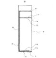
- 2 is a schematic sectional view of the protective cover 25, and
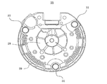
- FIG. 3 is a view of the protective cover 25 as viewed from the opening B side. 4 is an enlarged view of a portion A in FIG. 1, and
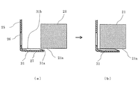
- FIG. 5 is a diagram showing a state in which the protective cover 25 is attached to the rotating electrical machine.
- the vehicle alternator 1 is used as an example of the rotating electrical machine.
- the vehicle alternator 1 has a casing 4 composed of an aluminum front bracket 2 and a rear bracket 3.
- a shaft 6 is rotatably supported on the casing 4 via a pair of bearings 5.
- the one end side of the shaft 6 extends to the outside of the front side of the casing 4 and the pulley 7 is fixed.
- a rotor 8 and a fan 11 are fixed to an intermediate portion of the shaft 6.
- a stator 12 is fixed inside the casing 4 so as to surround the rotor 8.
- the other end side of the shaft 6 is fixed to a pair of slip rings 15 that extend outside the rear side of the casing 4 and supply current to the rotor 8. Further, outside the rear side of the casing 4, a pair of brushes 16 that slide on the surface of each slip ring 15, a brush holder 17 that accommodates these brushes 16, a heat sink 18, a voltage regulator 19, A connector 20 and a rectifying device 21 are arranged.
- a protective cover 25 is attached to the rear bracket 3 of the casing 4 so as to cover the brush holder 17, the voltage regulator 19, the rectifier 21 and the like.
- the rotor 8 is a Landel-type rotor, and is provided with a field winding 9 that generates a magnetic flux when an excitation current is passed, and a pole core that covers the field winding 9 and forms a magnetic pole by the magnetic flux.
- the stator 12 is a cylindrical iron core 13 and a stator winding 14 wound around the iron core 13, and an alternating current is generated by a change in magnetic flux from the field winding 9 as the rotor 8 rotates. It has.
- the stator 12 is disposed so as to surround the rotor 8, and the iron core 13 of the stator 12 is sandwiched between the front bracket 2 and the rear bracket 3 from both sides in the axial direction.
- a field current is supplied from a battery (not shown) via the brush 16 and the slip ring 15 to the field winding 9 to generate a magnetic flux. Due to this magnetic flux, N poles and S poles are alternately formed on the outer periphery of the pole core 10 in the circumferential direction.
- the rotational torque of the engine is transmitted to the pulley 7 through a belt (not shown), and the shaft 6 and the rotor 8 rotate.
- a rotating magnetic field is applied to the stator winding 14 of the stator 12, and an electromotive force is generated in the stator winding 14.
- the AC electromotive force generated in the stator winding 14 is rectified to DC by the rectifier 21 and the magnitude of the output voltage is adjusted by the voltage regulator 19 to be applied to the battery or the on-vehicle electric load. Supplied.
- the fan 11 rotates in conjunction with the rotation of the rotor 8, and the outside air is sucked from the intake holes provided in the protective cover 25.
- the sucked outside air flows into the casing 4 after cooling the heat sink 18 of the voltage regulator 19 and the heat sink of the rectifier 21.
- the outside air that has flowed to the vicinity of the fan 11 is changed by the fan 11 in the circumferential direction of the rotating shaft, the portion of the stator winding 14 that extends from the iron core 13 is cooled, and the outside of the casing 4 is cooled. To be discharged.
- the protective cover 25 is made of an insulating resin such as polybutylene terephthalate (PBT) or nylon 66. As shown in FIG. 2, the protective cover 25 includes a substantially circular bottom portion 26 and a substantially cylindrical side wall 27 extending from the bottom portion 26 along the outer periphery of the bottom portion 26. The protective cover 25 is formed into a bottomed cylindrical shape with the end portion of the side wall 27 opposite to the bottom portion 26 forming a substantially circular opening B.
- PBT polybutylene terephthalate
- the bottom 26 of the protective cover 25 has a plurality of inner peripheral intake holes 28 and a plurality of outer peripheral sides as intake holes for cooling fluid sucked into the casing 4 by the fan 11.
- An intake hole 29 is provided.
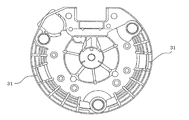
- guide ribs 31 are provided on the inner side of the side wall 27 of the protective cover 25 at three locations spaced apart from each other along the outer periphery of the bottom portion 26.
- Each of the three guide ribs 31 extends from the bottom portion 26 toward the opening B, and a chamfered portion 31 a is formed at the end of the guide rib 31 on the opening B side.
- FIG. 5 is a cross-sectional view showing a state in which the protective cover 25 is mounted in the vicinity of the rectifying device 21 constituting the vehicle alternator 1.
- the chamfered portion 31 a formed at the tip of the guide rib 31 is brought into contact with the side surface 21 a of the rectifying device 21. Thereby, the protective cover 25 is guided to an appropriate mounting position.
- the side surface of each component such as the rectifying device 21 refers to the surface in the direction along the rotational axis of the vehicle alternator 1 among the surfaces of each component.
- the top portion 31 b of the guide rib 31 is brought into contact with the side surface 21 a of the rectifying device 21, and the protective cover 25 is moved in the mounting direction while following the side surface 21 a of the rectifying device 21. And mounted on the vehicle alternator 1. Similarly, with respect to the other two guide ribs 31, the top portions 31b of the respective guide ribs 31 are brought into contact with the side surfaces of the other component parts.
- the top portions 31 b of the respective guide ribs 31 are in contact with the side surfaces of any of the components that constitute the vehicle alternator 1. Therefore, the height of each guide rib 31 from the side wall 27 is formed to be higher than the gap between the side surface of each component and the protective cover 25 with which the top portion 31 b of each guide rib 31 contacts.
- the height of the guide rib 31 is set to be greater than the gap between the side surface of each component and the protective cover 25 when the side wall 27 of the protective cover 25 is attached to the vehicle alternator 1. In consideration of elastic deformation.
- the protective cover 25 when the protective cover 25 is mounted on the vehicle alternator 1, the top portions 31b of the plurality of guide ribs 31 provided on the protective cover 25 are used for the vehicle. The side surfaces of a plurality of components constituting the AC generator 1 are brought into contact with each other. As a result, the protective cover 25 can be mounted while being positioned in the radial direction around the rotation axis of the vehicle alternator 1.
- the protective cover 25 by Embodiment 1 the shift
- the chamfered portion 31a is formed in a linear shape, but is not limited thereto, and may be formed in a curved shape, for example.
- each guide rib 31 in the rotation axis direction is from the bottom 26 to the vicinity of the opening B.
- the length is about half as in the guide rib 32 shown in FIG. May be.
- the side wall 27 is easily elastically deformed, and workability is improved.
- the lengths of the plurality of guide ribs 31 provided on the protective cover 25 may be different. That is, the guide rib 31 shown in FIG. 4 and the guide rib 32 shown in FIG. 6 that is shorter than the guide rib 31 shown in FIG. 4 may be mixed in one protective cover 25. In this case, first, the long guide rib 31 is used to roughly position the protective cover 25 with respect to the vehicle alternator 1. Next, the short guide rib 32 is used to position the rotating shaft of the vehicle alternator 1 in the radial direction. Thereby, the positioning property at the time of mounting
- the guide ribs 31 are arranged in three places, but the present invention is not limited to this.
- the guide ribs 31 is brought into contact with the side surface 21a of the rectifying device 21, but this is not restrictive.
- the guide rib 31 may be brought into contact with the side surface of the voltage regulator 19 or may be brought into contact with the side surface of another component.
- the rotating electrical machine is described as the vehicle alternator 1, but the present invention is not limited to this.
- the rotating electrical machine may be a vehicular motor or a vehicular generator motor.
Landscapes
- Engineering & Computer Science (AREA)
- Power Engineering (AREA)
- Physics & Mathematics (AREA)
- Thermal Sciences (AREA)
- Motor Or Generator Frames (AREA)
Abstract
回転電機の保護カバーは、略円形状に形成された底部と、底部の外周に沿って、底部から延出された側壁と、側壁の、底部と反対側の端部により形成される、略円形状の開口部とを有し、側壁の内側には、底部の外周に沿って、互いに離間して複数のガイドリブが設けられ、複数のガイドリブは、それぞれ、底部から開口部に向かって延出されるとともに、開口部側の端部に面取りが施されており、複数のガイドリブは、それぞれの頂部の、側壁からの高さが、回転電機に、保護カバーを装着したときに、それぞれの頂部が、構成部品の側面に接しうる高さに形成される。
Description
この発明は、回転電機の構成部品を保護するカバーの、回転電機への取り付け構造に関するものである。
特許文献1には、ケーシング内に配設された回転子と、ケーシングに支持された固定子と、ケーシングの外側に配設された整流器及び電圧調整器と、整流器及び電圧調整器を覆うように、ケーシングに装着される、底部と周壁部からなる筒形の保護カバーとを備えた車両用交流発電機において、保護カバーの内面に、整流器及び電圧調整器に設けた凹部に嵌合する凸部を設けることが記載されている。
近年は、車両の居住空間の拡大とともに、エンジンルームの小型化が求められており、車両用交流発電機についても、小型化が求められている。そして、車両用交流発電機に取り付けられる、整流器や電圧調整器といった機器にも、小型化の要望がある。しかしながら、特許文献1に記載された車両用交流発電機は、保護カバーの内面に設けた凸部と嵌合する凹部を、整流器及び電圧調整器に設ける必要があり、この凹部は、整流器及び電圧調整器を構成する電子部品等の配置に制約を生じさせ、小型化の障害となっていた。
また、特許文献1に記載された車両用交流発電機は、保護カバーの内面に設けた凸部を、整流器や電圧調整器に設けた凹部の深さ以上に形成することはできない。よって、保護カバーを取り付ける際に、凸部を凹部に対して位置決めすることが容易ではない。このため、凸部と凹部の位置がずれている場合には、保護カバーの凸部が、整流器や電圧調整器を構成する電子部品と干渉して、破損させてしまうという問題があった。
この発明は、上記のような課題を解決するためになされたものであり、整流器や電圧調整器に、保護カバーと嵌合する形状を設ける必要がなく、また、車両用交流発電機などの回転電機への取り付けが容易で、位置ずれすることのない保護カバーを得ることを目的とする。
この発明に係る回転電機の保護カバーは、略円形状に形成された底部と、底部の外周に沿って、底部から延出された側壁と、側壁の、底部と反対側の端部により形成される、略円形状の開口部とを有し、側壁の内側には、底部の外周に沿って、互いに離間して複数のガイドリブが設けられ、複数のガイドリブは、それぞれ、底部から開口部に向かって延出されるとともに、開口部側の端部に面取りが施されており、複数のガイドリブは、それぞれの頂部の、側壁からの高さが、回転電機に、保護カバーを装着したときに、それぞれの頂部が、構成部品の側面に接しうる高さに形成される。
この発明に係る保護カバーによれば、回転電機の構成部品を覆う保護カバーを、回転電機に装着するときに、保護カバーの側壁の内側に設けられた複数のガイドリブが、構成部品の側面に接触して、回転電機の回転軸の径方向において、保護カバーが位置決めされる。これにより、整流器や電圧調整器などの、回転電機の構成部品に、保護カバーと嵌合する形状を設ける必要がなく、また、回転電機への取り付けが容易で、位置ずれすることのない保護カバーを得ることができる。
以下、本発明による回転電機の保護カバーの好適な実施の形態につき、図面を用いて説明する。
実施の形態1.
図1は、本発明の実施の形態1における保護カバー25が取り付けられた、回転電機の断面図である。図2は、保護カバー25の概略断面図であり、図3は、保護カバー25を開口部B側からみた図である。また、図4は、図1のA部の拡大図であり、図5は、保護カバー25を、回転電機に取付ける様子を示した図である。なお、実施の形態1では、回転電機の一例として、車両用交流発電機1を用いている。
図1は、本発明の実施の形態1における保護カバー25が取り付けられた、回転電機の断面図である。図2は、保護カバー25の概略断面図であり、図3は、保護カバー25を開口部B側からみた図である。また、図4は、図1のA部の拡大図であり、図5は、保護カバー25を、回転電機に取付ける様子を示した図である。なお、実施の形態1では、回転電機の一例として、車両用交流発電機1を用いている。
図1に示すように、車両用交流発電機1は、アルミニウム製のフロントブラケット2とリヤブラケット3とからなるケーシング4を有する。ケーシング4には、一対の軸受5を介して、シャフト6が、回転自在に支持されている。
シャフト6の一端側は、ケーシング4のフロント側の外部に延出して、プーリ7が固着されている。シャフト6の中間部には、回転子8とファン11が固定されている。そして、ケーシング4の内部には、回転子8を囲繞するように固定子12が固定されている。
シャフト6の他端側は、ケーシング4のリヤ側の外部に延出して、回転子8に電流を供給する一対のスリップリング15が固定されている。また、ケーシング4のリヤ側の外部には、各スリップリング15の表面に摺動する一対のブラシ16と、これらのブラシ16を収容するブラシホルダ17と、ヒートシンク18と、電圧調整器19と、コネクタ20と、整流装置21とが配置される。
そして、ケーシング4のリヤブラケット3には、これらブラシホルダ17、電圧調整器19、整流装置21などを覆うように、保護カバー25が装着されている。
回転子8は、ランデル型回転子であり、励磁電流が流されて磁束を発生する界磁巻線9と、界磁巻線9を覆うように設けられ、その磁束によって磁極が形成されるポールコア10と、を備えている。また、固定子12は、円筒状の鉄心13と、鉄心13に巻装され、回転子8の回転に伴い、界磁巻線9からの磁束の変化で交流が生じる固定子巻線14と、を備えている。固定子12は、回転子8を取り囲むように配設されており、固定子12の鉄心13は、フロントブラケット2およびリヤブラケット3により、軸方向の両側から挟持されている。
このように構成された車両用交流発電機1には、図示しないバッテリから、ブラシ16、スリップリング15を介して、界磁巻線9に界磁電流が供給されて、磁束が発生する。この磁束により、N極とS極とがポールコア10の外周に、周方向に交互に形成される。
一方、図示しないベルトを介して、エンジンの回転トルクが、プーリ7に伝達され、シャフト6及び回転子8が回転する。そして、回転磁界が、固定子12の固定子巻線14に与えられ、起電力が、固定子巻線14に発生する。さらに、固定子巻線14に発生した交流の起電力が、整流装置21により直流に整流されるとともに、その出力電圧の大きさが、電圧調整器19により調整されて、バッテリや車載電気負荷に供給される。
また、ファン11が、回転子8の回転に連動して回転し、外気が、保護カバー25に設けられた吸気孔から吸気される。吸気された外気は、電圧調整器19のヒートシンク18や、整流装置21のヒートシンクを冷却した後、ケーシング4内に流入する。そして、ファン11の近傍まで流れてきた外気は、ファン11により、回転軸の周方向に流れを変え、固定子巻線14の、鉄心13から延出する部位を冷却して、ケーシング4の外部に排出される。
次に、図2ないし図5を参照して、保護カバー25及び保護カバー25の取り付けについて説明する。
保護カバー25は、ポリブチレンテレフタレート(PBT)、ナイロン66などの絶縁性樹脂により形成される。図2に示すように、保護カバー25は、略円形状の底部26と、底部26の外周に沿って、底部26から延出された、略円筒状の側壁27とを有している。そして、保護カバー25は、側壁27の、底部26と反対側の端部が、略円形状の開口部Bを形成して、有底円筒状に成型されている。
また、図3に示すように、保護カバー25の底部26には、ファン11によりケーシング4内に吸引される、冷却用流体の吸気孔として、複数の内周側吸気孔28及び複数の外周側吸気孔29が設けられている。
そして、図2ないし図4に示すように、保護カバー25の側壁27の内側には、底部26の外周に沿って、互いに離間した3箇所に、それぞれガイドリブ31が設けられている。3つのガイドリブ31は、それぞれ、底部26から開口部Bに向かって延設されており、ガイドリブ31の、開口部B側の端部には、面取り部31aが形成されている。
次に、図5を参照して、車両用交流発電機1に、保護カバー25を装着する様子を説明する。図5は、車両用交流発電機1を構成する、整流装置21の近傍に、保護カバー25が装着される様子を、断面図で示している。
保護カバー25を装着する際は、まず、図5(a)に示すように、ガイドリブ31の先端に形成された面取り部31aを、整流装置21の側面21aに接触させる。これにより、保護カバー25は、適切な装着位置に案内される。なお、本発明において、整流装置21などの各構成部品の側面とは、各構成部品の表面のうち、車両用交流発電機1の回転軸に沿う方向の面をいうものとする。
次に、図5(b)に示すように、ガイドリブ31の頂部31bを、整流装置21の側面21aに接触させ、保護カバー25を、整流装置21の側面21aに倣わせながら、装着方向に移動させて、車両用交流発電機1に装着する。他の2つのガイドリブ31についても同様に、各ガイドリブ31の頂部31bを、他の構成部品の側面に接触させる。
そして、車両用交流発電機1に保護カバー25が装着されたとき、各ガイドリブ31の頂部31bは、車両用交流発電機1を構成するいずれかの構成部品の側面に接触した状態となる。したがって、各ガイドリブ31の、側壁27からの高さは、各ガイドリブ31の頂部31bが接触する、各構成部品の側面と、保護カバー25との隙間以上の高さに形成される。なお、ここで、ガイドリブ31の高さを、各構成部品の側面と、保護カバー25との隙間以上としたのは、保護カバー25の側壁27が、車両用交流発電機1に装着した際に、弾性変形することを考慮したものである。
このように、実施の形態1による保護カバー25によれば、車両用交流発電機1に保護カバー25を装着する際に、保護カバー25に設けられた複数のガイドリブ31の頂部31bを、車両用交流発電機1を構成する複数の構成部品の側面に、それぞれ接触させる。これにより、車両用交流発電機1の、回転軸を中心とする径方向において、保護カバー25を位置決めしながら装着することができる。
そして、実施の形態1による保護カバー25によれば、車両用交流発電機1を車両に搭載した時の振動に対し、ケーシング4に対する、保護カバー25の回転軸の径方向のずれを抑制することができる。さらに、保護カバー25のガイドリブ31は、各構成部品の側面と保護カバー25との隙間を利用して、保護カバー25に設けられるので、各構成部品の配置や構造に制約を設ける必要が無い。つまり、整流装置21の形状や配置を変えることなく、保護カバー25を形成することができる。
なお、実施の形態1では、面取り部31aを、直線状に形成しているが、これに限るものではなく、例えば、曲線状に形成してもよい。
また、実施の形態1では、各ガイドリブ31の、回転軸方向の長さを、底部26から開口部B付近までとしているが、図6に示したガイドリブ32のように、半分程度の長さにしてもよい。この場合、側壁27が弾性変形しやすくなり、作業性が向上する。
さらに、保護カバー25に設ける複数のガイドリブ31の長さを、異なる長さとしてもよい。つまり、図4に示したガイドリブ31と、図6に示した、図4のガイドリブ31よりも長さの短いガイドリブ32を、一つの保護カバー25に、混在させてもよい。この場合、まず長いガイドリブ31を用いて、車両用交流発電機1に対する、保護カバー25の粗い位置決めを行なう。次に、短いガイドリブ32を用いて、車両用交流発電機1の回転軸の径方向の位置決めを行う。これにより、保護カバー25を装着する際の位置決め性を、向上させることができる。
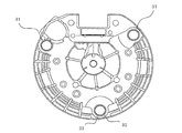
また、実施の形態1では、ガイドリブ31を3箇所に配置したが、これに限るものではない。例えば、図7に示すように、4箇所に配置してもよいし、図8に示すように、2箇所にして、対向するように配置してもよい。そして、実施の形態1では、ガイドリブ31の1つを、整流装置21の側面21aに接触させていたが、これに限るものではない。例えば、ガイドリブ31を、電圧調整器19の側面に接触させるようにしてもよいし、他の構成部品の側面に接触させるようにしてもよい。
さらに、実施の形態1では、回転電機を車両用交流発電機1として説明しているが、これに限るものでもない。例えば、回転電機は、車両用電動機や、車両用発電電動機などであってもよい。
1 車両用交流発電機1、2 フロントブラケット、3 リヤブラケット、4 ケーシング、6 シャフト、19 電圧調整器、21 整流装置、21a 側面、25 保護カバー、26 底部、27 側壁、31,32 ガイドリブ、31a 面取り部、31b 頂部、B 開口部。
Claims (4)
- 略円形状に形成された底部と、
前記底部の外周に沿って、前記底部から延出された側壁と、
前記側壁の、前記底部と反対側の端部により形成される、略円形状の開口部とを有する、回転電機の構成部品を保護する保護カバーであって、
前記側壁の内側には、前記底部の外周に沿って、互いに離間して複数のガイドリブが設けられ、
前記複数のガイドリブは、それぞれ、前記底部から前記開口部に向かって延出されるとともに、前記開口部側の端部に面取りが施されており、
前記複数のガイドリブは、それぞれの頂部の、前記側壁からの高さが、
前記回転電機に、前記保護カバーを装着したときに、前記それぞれの頂部が、
前記構成部品の側面に接しうる高さに形成される、回転電機の保護カバー。 - 前記複数のガイドリブのうち、少なくとも1つのガイドリブにおける、
前記底部から前記開口部側の端部までの長さは、他のガイドリブにおける、前記底部から前記開口部側の端部までの長さと異なる、請求項1に記載の回転電機の保護カバー。 - 前記構成部品は、整流装置を含み、
前記複数のガイドリブのうち、少なくとも1つのガイドリブは、
前記回転電機に前記保護カバーを装着したときに、前記整流装置の側面に接触する、請求項1または2に記載の回転電機の保護カバー。 - 前記構成部品は、電圧調整器を含み、
前記複数のガイドリブのうち、少なくとも1つのガイドリブは、
前記回転電機に前記保護カバーを装着したときに、前記電圧調整器の側面に接触する、
請求項1から3のいずれか1項に記載の回転電機の保護カバー。
Priority Applications (6)
| Application Number | Priority Date | Filing Date | Title |
|---|---|---|---|
| CN201680090690.1A CN109923763B (zh) | 2016-11-16 | 2016-11-16 | 旋转电机的保护罩 |
| MX2019005434A MX395732B (es) | 2016-11-16 | 2016-11-16 | Cubierta protectora para maquina electrica giratoria |
| PCT/JP2016/083945 WO2018092208A1 (ja) | 2016-11-16 | 2016-11-16 | 回転電機の保護カバー |
| JP2018550913A JP6752897B2 (ja) | 2016-11-16 | 2016-11-16 | 回転電機の保護カバー |
| EP16922009.2A EP3544155B1 (en) | 2016-11-16 | 2016-11-16 | Protective cover for dynamo-electric machine |
| US16/345,003 US11025128B2 (en) | 2016-11-16 | 2016-11-16 | Protective cover for rotary electric machine |
Applications Claiming Priority (1)
| Application Number | Priority Date | Filing Date | Title |
|---|---|---|---|
| PCT/JP2016/083945 WO2018092208A1 (ja) | 2016-11-16 | 2016-11-16 | 回転電機の保護カバー |
Publications (1)
| Publication Number | Publication Date |
|---|---|
| WO2018092208A1 true WO2018092208A1 (ja) | 2018-05-24 |
Family
ID=62145301
Family Applications (1)
| Application Number | Title | Priority Date | Filing Date |
|---|---|---|---|
| PCT/JP2016/083945 Ceased WO2018092208A1 (ja) | 2016-11-16 | 2016-11-16 | 回転電機の保護カバー |
Country Status (6)
| Country | Link |
|---|---|
| US (1) | US11025128B2 (ja) |
| EP (1) | EP3544155B1 (ja) |
| JP (1) | JP6752897B2 (ja) |
| CN (1) | CN109923763B (ja) |
| MX (1) | MX395732B (ja) |
| WO (1) | WO2018092208A1 (ja) |
Citations (3)
| Publication number | Priority date | Publication date | Assignee | Title |
|---|---|---|---|---|
| JPS6051756U (ja) * | 1983-09-16 | 1985-04-11 | 株式会社日立製作所 | モ−タ−外突保護カバ− |
| JPH11299140A (ja) * | 1998-04-14 | 1999-10-29 | Nippon Densan Corp | モータにおけるステータの取付構造 |
| JP2016021864A (ja) * | 2015-08-18 | 2016-02-04 | 三菱電機株式会社 | 交流発電機 |
Family Cites Families (12)
| Publication number | Priority date | Publication date | Assignee | Title |
|---|---|---|---|---|
| US4713568A (en) * | 1985-09-26 | 1987-12-15 | Siemens Aktiengesellschaft | Closed motor/transmission unit |
| DE69615307T2 (de) * | 1995-10-19 | 2002-07-25 | Denso Corp., Kariya | Drehmaschineanlasser für Kraftfahrzeug |
| DE10361860A1 (de) | 2003-12-30 | 2005-07-28 | Robert Bosch Gmbh | Schutzkappe, insbesondere für einen Drehstromgenerator |
| JP4797779B2 (ja) * | 2006-04-27 | 2011-10-19 | 株式会社デンソー | 車両用交流発電機 |
| JP5354888B2 (ja) * | 2007-11-05 | 2013-11-27 | 株式会社ミツバ | ブラシレスモータ |
| DE102009010782A1 (de) * | 2009-02-26 | 2010-09-09 | Bühler Motor GmbH | Stator für einen elektronisch kommutierten Gleichstrommotor |
| CN102668337B (zh) | 2009-11-24 | 2015-05-20 | 三菱电机株式会社 | 车辆用交流发电机 |
| CN103004059B (zh) * | 2010-07-14 | 2016-05-18 | 松下知识产权经营株式会社 | 无刷电机及其制造方法 |
| EP2779368B1 (en) | 2011-11-11 | 2021-03-03 | Mitsubishi Electric Corporation | Rotating electrical machine for vehicle |
| EP2840685B1 (en) | 2012-04-18 | 2018-08-22 | Mitsubishi Electric Corporation | Ac generator |
| JP5832507B2 (ja) * | 2013-11-21 | 2015-12-16 | 三菱電機株式会社 | 交流発電機 |
| CN106026479B (zh) | 2016-07-29 | 2018-10-23 | 苏州工业园区星德胜电机有限公司 | 电动机外壳及包括该外壳的低振动电动机 |
-
2016
- 2016-11-16 WO PCT/JP2016/083945 patent/WO2018092208A1/ja not_active Ceased
- 2016-11-16 JP JP2018550913A patent/JP6752897B2/ja not_active Expired - Fee Related
- 2016-11-16 US US16/345,003 patent/US11025128B2/en not_active Expired - Fee Related
- 2016-11-16 EP EP16922009.2A patent/EP3544155B1/en not_active Not-in-force
- 2016-11-16 MX MX2019005434A patent/MX395732B/es unknown
- 2016-11-16 CN CN201680090690.1A patent/CN109923763B/zh not_active Expired - Fee Related
Patent Citations (3)
| Publication number | Priority date | Publication date | Assignee | Title |
|---|---|---|---|---|
| JPS6051756U (ja) * | 1983-09-16 | 1985-04-11 | 株式会社日立製作所 | モ−タ−外突保護カバ− |
| JPH11299140A (ja) * | 1998-04-14 | 1999-10-29 | Nippon Densan Corp | モータにおけるステータの取付構造 |
| JP2016021864A (ja) * | 2015-08-18 | 2016-02-04 | 三菱電機株式会社 | 交流発電機 |
Non-Patent Citations (1)
| Title |
|---|
| See also references of EP3544155A4 * |
Also Published As
| Publication number | Publication date |
|---|---|
| JP6752897B2 (ja) | 2020-09-09 |
| EP3544155A4 (en) | 2019-11-27 |
| MX2019005434A (es) | 2019-07-10 |
| EP3544155A1 (en) | 2019-09-25 |
| US20190273411A1 (en) | 2019-09-05 |
| CN109923763B (zh) | 2022-05-13 |
| EP3544155B1 (en) | 2021-10-06 |
| US11025128B2 (en) | 2021-06-01 |
| MX395732B (es) | 2025-03-25 |
| CN109923763A (zh) | 2019-06-21 |
| JPWO2018092208A1 (ja) | 2019-03-07 |
Similar Documents
| Publication | Publication Date | Title |
|---|---|---|
| JP4887128B2 (ja) | 回転電機 | |
| JP5247787B2 (ja) | 車両用回転電機 | |
| JP4858505B2 (ja) | 車両用回転電機 | |
| KR100874317B1 (ko) | 차량용 교류 발전기 | |
| JP5345164B2 (ja) | 車両用回転電機 | |
| JP5976217B2 (ja) | 回転電機 | |
| JP2011004501A (ja) | 回転電機 | |
| JP5631511B2 (ja) | 回転電機 | |
| JP4089623B2 (ja) | 回転電機 | |
| JP2004254371A (ja) | 回転電機 | |
| JP2007228677A (ja) | 発電装置及び回転電機 | |
| CN105684271B (zh) | 车用旋转电机 | |
| JP5752320B2 (ja) | 交流発電機 | |
| JP6351857B2 (ja) | 車両用回転電機 | |
| JP6234603B2 (ja) | 車両用回転電機 | |
| JP5495945B2 (ja) | 回転電機 | |
| JP6752897B2 (ja) | 回転電機の保護カバー | |
| JP4400577B2 (ja) | ブラシレス車両用交流発電機 | |
| JP2014112983A (ja) | 回転電機 | |
| JP2019537418A (ja) | 回転電気機械用のロータ | |
| JP2016021864A (ja) | 交流発電機 |
Legal Events
| Date | Code | Title | Description |
|---|---|---|---|
| ENP | Entry into the national phase |
Ref document number: 2018550913 Country of ref document: JP Kind code of ref document: A |
|
| 121 | Ep: the epo has been informed by wipo that ep was designated in this application |
Ref document number: 16922009 Country of ref document: EP Kind code of ref document: A1 |
|
| NENP | Non-entry into the national phase |
Ref country code: DE |
|
| ENP | Entry into the national phase |
Ref document number: 2016922009 Country of ref document: EP Effective date: 20190617 |