WO2018092497A1 - 塗装方法および塗装フィルム - Google Patents
塗装方法および塗装フィルム Download PDFInfo
- Publication number
- WO2018092497A1 WO2018092497A1 PCT/JP2017/037682 JP2017037682W WO2018092497A1 WO 2018092497 A1 WO2018092497 A1 WO 2018092497A1 JP 2017037682 W JP2017037682 W JP 2017037682W WO 2018092497 A1 WO2018092497 A1 WO 2018092497A1
- Authority
- WO
- WIPO (PCT)
- Prior art keywords
- transfer layer
- holes
- support sheet
- coating film
- vertical direction
- Prior art date
- Legal status (The legal status is an assumption and is not a legal conclusion. Google has not performed a legal analysis and makes no representation as to the accuracy of the status listed.)
- Ceased
Links
Images



Classifications
-
- B—PERFORMING OPERATIONS; TRANSPORTING
- B44—DECORATIVE ARTS
- B44C—PRODUCING DECORATIVE EFFECTS; MOSAICS; TARSIA WORK; PAPERHANGING
- B44C1/00—Processes, not specifically provided for elsewhere, for producing decorative surface effects
- B44C1/16—Processes, not specifically provided for elsewhere, for producing decorative surface effects for applying transfer pictures or the like
- B44C1/165—Processes, not specifically provided for elsewhere, for producing decorative surface effects for applying transfer pictures or the like for decalcomanias; sheet material therefor
- B44C1/17—Dry transfer
- B44C1/1733—Decalcomanias applied under pressure only, e.g. provided with a pressure sensitive adhesive
-
- B—PERFORMING OPERATIONS; TRANSPORTING
- B32—LAYERED PRODUCTS
- B32B—LAYERED PRODUCTS, i.e. PRODUCTS BUILT-UP OF STRATA OF FLAT OR NON-FLAT, e.g. CELLULAR OR HONEYCOMB, FORM
- B32B27/00—Layered products comprising a layer of synthetic resin
Definitions
- the present invention relates to a coating method and a coating film.
- the coated film is provided with a transfer layer on a support sheet.
- the transfer layer is made of a paint and has a desired pattern shape.
- the transfer layer is transferred to the substrate surface by pressing the transfer layer of the coating film against the substrate surface.
- the transfer layer is transferred to the substrate surface by pressing the coating film from the support sheet side with a pressing means such as a roller or a squeegee. During this transfer, bubbles may be caught between the coating film and the substrate surface.
- the adhesion between the transfer layer and the substrate surface decreases. If air bubbles remain between the transfer layer and the substrate surface, there is a concern that the appearance quality of the decoration (pattern) may be deteriorated, or that defects such as damage due to changes in atmospheric pressure may occur.
- Patent Document 1 discloses a method of defoaming bubbles in an SMC sheet made of a double film.
- a double film having air holes in the upper film is passed through a plurality of upper and lower rollers to defoam bubbles. Since the method described in Patent Document 1 passes through a roller, it cannot be applied to defoaming bubbles entrained between the substrate surface and the transfer layer.
- the present invention has been made in view of such circumstances, and an object of the present invention is to provide a coating method and a coating film in which bubbles do not remain between the substrate surface and the transfer layer.
- a coating film having a transfer layer on a support sheet is formed with a plurality of through holes penetrating only the transfer layer, and after the through holes are formed, the coating film is The coating film is arranged so as to face the object surface, and the coating film is pressed from the support sheet side to the object surface so that the transfer layer is transferred to the object surface.
- a coating method for peeling from the transfer layer is provided.
- the plurality of through-holes act as air bubble vents that guide the air bubbles trapped between the object surface and the transfer layer between the transfer layer and the support sheet.
- the bubbles introduced between the transfer layer and the support sheet are integrated with the atmosphere when the support sheet is peeled off. As a result, it is possible to prevent damage due to a decrease in adhesion between the surface of the object and the transfer layer, a decrease in appearance quality, a decrease in atmospheric pressure and the like.
- a vertical direction on the surface of the transfer layer is defined, and the plurality of through holes are arranged at intervals along the vertical direction. It is preferable to form the plurality of through holes so as to form a row and the through holes of an arbitrary row are displaced in the vertical direction with respect to the through holes of the adjacent row.
- the present invention includes a support sheet and a transfer layer that is releasably supported by the support sheet, the transfer layer includes a plurality of through holes, and the through holes are arranged in a predetermined vertical direction.
- a coating film in which a plurality of rows are formed side by side along a space, and through holes in an arbitrary row are arranged so as to be displaced in the vertical direction with respect to through holes in adjacent rows.
- the transfer layer after forming a plurality of through holes in the transfer layer, the transfer layer can be transferred to the surface of the object so that no bubbles remain by pressing the coating film against the surface of the object.
- FIG. 1 is an exploded perspective view of a paint film according to the present embodiment.
- 2A is a cross-sectional view taken along line AA of the painted film shown in FIG. 1
- FIG. 2B is a cross-sectional view taken along line BB of the painted film shown in FIG.
- the coating film 1 includes a support sheet 2 and a transfer layer 3 supported on the support sheet 2.
- the support sheet 2 supports the transfer layer 3.
- the support sheet 2 has liquid-tightness that does not allow the transfer layer 3 to pass therethrough.
- the support sheet 2 has releasability from the transfer layer 3.
- the support sheet 2 has a smooth surface.
- the “smooth surface” can impart desired smoothness to the surface of the transfer layer that comes into contact.
- the material of the support sheet 2 is, for example, polyester, polyolefin, paper subjected to a release treatment, or the like.
- the support sheet 2 does not have adhesiveness to the object surface.
- the transfer layer 3 has a desired pattern and is transferred to decorate the surface of the object.
- the transfer layer 3 is mainly composed of a paint.
- the paint is made of a material suitable for the object.
- a paint sold for aircraft can be used.
- Aircraft paints have the flexibility to cope with changes in external atmospheric pressure.
- the paint may contain elements (ink, additives, etc.) necessary for the formation of the pattern.
- the transfer layer 3 is in close contact with the support sheet to such an extent that it is supported by the support sheet 2 even if it is reversed upside down.
- the transfer layer 3 includes a plurality of through holes 4.
- the plurality of through-holes 4 are arranged along the predetermined vertical direction X at intervals, and form a plurality of rows T 1 , T 2 ... T n (n is an arbitrary natural number).
- the plurality of through holes 4 are arranged at intervals along the left-right direction and form a plurality of rows S 1 , S 2 ... S m (m is an arbitrary natural number).
- the “vertical direction” is a direction appropriately determined according to the pattern of the transfer layer 3 and the use of the object.
- the transfer layer (decoration layer) 5 transferred to the surface of the object, there is a direction (main viewing direction) that the viewer will mainly browse.
- “upper and lower” means the upper side of the line of sight and the lower side of the line of sight when the picture is viewed from the main viewing direction.
- the “left / right direction” is a direction orthogonal to the up / down direction.
- a virtual line P connecting adjacent through holes 4 has a net shape.
- the net shape may be a square.
- the net 6 may have an angle Q with respect to the vertical direction or the horizontal direction.
- the angle Q of the net 6 is ⁇ 15 degrees or more and ⁇ 75 degrees or less, preferably ⁇ 45 degrees with respect to the vertical direction.
- the diameter of the through hole 4 is 1.0 mm or less, preferably 0.3 mm or more and 0.7 mm or less.
- interval R (distance between hole centers) of the adjacent through-hole 4 is 5.0 mm or more and 30 mm or less, for example, 10 mm.
- the thickness of the transfer layer 3 is 25 ⁇ m or more and 100 ⁇ m or less.
- FIGS. 3 and 4 illustrate the arrangement of the through holes 4.
- a plurality of through holes 4 are arranged on the surface of the transfer layer 3 at equal intervals in two directions (up and down, left and right) to form a plurality of columns and rows.
- the through-hole 4 of an arbitrary column T 1 is arranged to shift up and down relative to the through-hole 4 of the adjacent row T 2.
- the plurality of through holes 4 are staggered.
- the net 6 is square and has an angle of ⁇ 45 degrees with respect to the vertical direction X.
- the painting method according to the present embodiment can be applied to painting aircraft, ships, railway vehicles, and the like.
- the aircraft substrate surface 10 is an object.
- a transfer layer 3 is formed by printing a paint.
- a known technique can be applied to the printing method. After printing, the solvent of the paint is volatilized appropriately so that the viscosity of the through hole 4 is not closed. Since the transfer layer 3 of a commercially available coating film has a viscosity that does not close the through hole 4, a commercially available product can also be used.
- a plurality of through holes 4 are formed in the transfer layer 3.
- the vertical direction X on the surface of the transfer layer 3 is determined in advance.
- the plurality of through holes 4 are arranged so as to form a plurality of rows side by side along the predetermined vertical direction X at intervals.
- the plurality of through holes 4 are arranged as shown in FIGS. As shown in FIG. 4, the plurality of through holes 4 may be formed such that the through holes 4 in any row are displaced in the vertical direction X with respect to the through holes 4 in the adjacent rows.
- the through-hole 4 is formed using a punch member (not shown) so as to penetrate only the transfer layer 3 without penetrating the support sheet 2.
- the piercing member is, for example, an engraving machine, a cutting plotter, a laser processing machine, or the like.
- the engraving machine can form the through hole 4 only in the transfer layer 3 without penetrating the support sheet 2 by setting the movement distance of the Y axis of the spindle to the thickness of the transfer layer 3. By not allowing the support sheet 2 to penetrate, it is possible to prevent the coating material of the transfer layer 3 from oozing out from the support sheet by pressing during transfer.
- the substrate surface 10 Prior to painting, the substrate surface 10 is made clean and dry as necessary. For example, the substrate surface 10 is cleaned using isopropyl alcohol. If necessary, surface treatment such as sanding may be performed before cleaning.
- the coating area on the substrate surface is surrounded by the masking material 11 (see FIG. 5A).
- Adhesive paint is applied to the coating area of the substrate surface 10 to form an adhesive coating film 12 (see FIG. 5A).
- the adhesive coating film 12 has adhesiveness but does not adhere to what is touched when touched with a finger or the like.
- Examples of the adhesive paint include polyurethane paint and lacquer paint.
- the coating film 1 in which the through holes 4 are formed in the transfer layer 3 is arranged so that the transfer layer 3 faces the substrate surface 10. At that time, the vertical direction X of the transfer layer 3 is aligned with the upper side and the lower side when the coating area of the substrate surface 10 is viewed from the main viewing direction.
- the transfer film 3 is transferred to the substrate surface 10 by pressing the coating film 1 against the substrate surface 10 from the support sheet 2 side.
- the transfer layer 3 is positioned so as to be within the range surrounded by the masking material 11, and one end of the coating film 1 is fixed to the substrate surface 10.
- the pressing member 13 is pressed onto the support sheet 2 at the fixed one end side and is slid toward the other end side. As a result, the transfer layer 3 is transferred to the substrate surface 10 and becomes the decorative layer 5.
- the pressing member 13 is a squeegee, a roller, or the like.
- the support sheet 2 After confirming that the transfer layer 3 has been transferred to the substrate surface 10, the support sheet 2 is peeled off from the decorative layer 5 (see FIG. 5C).
- a protective coating is applied to the surface of the transferred transfer layer (decoration layer) 5 using an application member 14 such as a roller (see FIG. 5D).
- the protective coating is made of a material that can impart durability and appearance quality to the decorative layer 5.
- the protective paint is, for example, polyurethane paint or lacquer paint.
- the masking material 11 is removed (see FIG. 5E).
- FIG. 6 shows a state of the transfer layer (decoration layer) 5 transferred to the substrate-side surface of the aircraft 16.
- the main viewing direction is a direction horizontal to the ground (the depth direction on the paper)
- the vertical direction X is a direction along the direction of gravity.
- a plurality of through holes 4 are arranged in a row along a predetermined vertical direction X so as to form a plurality of rows, and the through holes 4 in any row are connected to the through holes 4 in adjacent rows. It arrange
- the coating layer 1 is pressed to transfer the transfer layer 3.
- bubbles entrained between the transfer layer 3 and the substrate surface 10 move to the back side of the transfer layer 3 (the support sheet 2 side) through the through holes 4.
- the bubbles that have moved to the back side are diffused into the atmosphere by peeling the support sheet 2. Thereby, it is possible to prevent bubbles from remaining between the transfer layer 3 and the substrate surface 10 and to improve the adhesion between the transfer layer 3 and the substrate surface 10.
- the through holes 4 are displayed in a size different from the actual scale in order to clarify the arrangement of the through holes 4.
- the through hole 4 having a diameter of 0.3 mm or more and 0.7 mm or less cannot be visually confirmed from a distance.
- the presence of the through-holes 4 may be confirmed when approaching about 3 m, but it is difficult to confirm the presence by shifting the through-holes in adjacent rows in the vertical direction as shown in FIG. Thereby, the appearance quality can be improved.
- the same effect can be obtained even if the substrate surface 10 onto which the transfer layer 3 is transferred is a curved surface.
Landscapes
- Decoration By Transfer Pictures (AREA)
- Laminated Bodies (AREA)
- Application Of Or Painting With Fluid Materials (AREA)
Abstract
基体表面と転写層との間に気泡が残存しないような塗装方法および塗装フィルムを提供することを目的とする。本発明の塗装方法では、支持体シート2上に転写層3を備えた塗装フィルム1に、該転写層3のみを貫通する複数の貫通孔4を形成し、前記複数の貫通孔4を形成した後に、前記塗装フィルム1を、前記転写層3が前記対象物表面10に向くよう配置し、前記転写層3が前記対象物表面10に転写されるよう、前記塗装フィルム1を支持体シート2側から前記対象物表面10に押圧し、前記押圧後に、前記支持体シート2を前記転写層3(装飾層5)から剥離する。
Description
本発明は、塗装方法および塗装フィルムに関するものである。
航空機などの基体表面を装飾する方法として、塗装フィルムを用いて絵柄を転写する技術が知られている。
塗装フィルムは、支持体シート上に転写層を備えたものである。転写層は、塗料からなり、所望の絵柄の形状となっている。塗装フィルムの転写層を基体表面に押し付けることで、転写層が基体表面に転写される。
一般に、塗装フィルムを支持体シート側からローラやスキージなどの押圧手段で押し付けて、転写層を基体表面に転写させる。この転写の際に、塗装フィルムと基体表面との間に気泡が巻き込まれることがある。
気泡が巻き込まれると、転写層と基体表面との密着性が低下する。転写層と基体表面との間に気泡が残存していると、装飾(絵柄)の外観品質の低下や、気圧変化による破損等の不具合が発生する懸念がある。
特許文献1には、二重フィルムからなるSMCシート内の気泡を脱泡する方法を開示している。特許文献1では、上フィルムに空気穴をあけた二重フィルムを上下複数本のローラに通過させて気泡を脱泡している。特許文献1に記載の方法は、ローラを通過させるため、基体表面と転写層との間に巻き込まれた気泡の脱泡には適用できない。
本発明は、このような事情に鑑みてなされたものであって、基体表面と転写層との間に気泡が残存しないような塗装方法および塗装フィルムを提供することを目的とする。
本発明は、支持体シート上に転写層を備えた塗装フィルムに、該転写層のみを貫通する複数の貫通孔を形成し、前記貫通孔を形成した後に、前記塗装フィルムを、前記転写層が前記対象物表面に向くよう配置し、前記転写層が前記対象物表面に転写されるよう、前記塗装フィルムを支持体シート側から前記対象物表面に押圧し、前記押圧後に、前記支持体シートを前記転写層から剥離する塗装方法を提供する。
複数の貫通孔は、対象物表面と転写層との間に巻き込まれた気泡を、転写層と支持体シートとの間に導く気泡抜き孔として作用する。転写層と支持体シートとの間に導かれた気泡は、支持体シートを剥離した際に大気と一体化する。これにより、対象物表面と転写層との密着性低下、外観品質の低下および気圧低下等による破損を防止できる。
上記発明の一態様では、前記複数の貫通孔を形成する工程において、前記転写層の面上の上下方向を定め、前記複数の貫通孔が前記上下方向に沿って間隔をあけて並んで複数の列を成し、任意の列の貫通孔が、隣接する列の貫通孔に対して前記上下方向にずれるよう前記複数の貫通孔を形成することが好ましい。
隣接する列の貫通孔の位置を上下方向にずらすことで、転写層における貫通孔の存在を視覚的に目立たなくさせることができる。これにより、外観品質を向上させられ得る。
本発明は、支持体シートと、剥離可能に前記支持体シートで支持されている転写層と、を備え、前記転写層が、複数の貫通孔を備え、前記貫通孔が、所定の上下方向に沿って間隔をあけて並んで複数の列を成し、任意の列の貫通孔が、隣接する列の貫通孔に対して前記上下方向にずれるよう配置されている塗装フィルムを提供する。
本発明によれば、転写層に複数の貫通孔を形成してから、塗装フィルムを対象物表面に押圧することで、気泡が残存しないように転写層を対象物表面に転写できる。
以下に、本発明に係る塗装方法および塗装フィルムの一実施形態について、図面を参照して説明する。図1は、本実施形態に係る塗装フィルムの分解斜視図である。図2の(A)は図1に示した塗装フィルムのA-A断面図、(B)は図1示した塗装フィルムのB-B断面図である。
塗装フィルム1は、支持体シート2と、支持体シート2上に支持されている転写層3とを備えている。
支持体シート2は、転写層3を支持するものである。支持体シート2は、転写層3を透過させない液密性を有する。支持体シート2は、転写層3に対して剥離性を有する。支持体シート2は、平滑な表面を有する。「平滑な表面」は、接触する転写層表面に所望の平滑性を付与できる。支持体シート2の材料は、例えば、ポリエステル、ポリオレフィン、離形処理をした紙などである。支持体シート2は、対象物表面に対する接着性は有していない。
転写層3は、所望の絵柄を有し、転写されて対象物表面を装飾するものである。転写層3は、主に塗料で構成されている。塗料は、対象物に適した材質のものが使用される。例えば、対象物が航空機の基体である場合、航空機用として販売されている塗料を用いることができる。航空機用の塗料は、外気圧変化に対応できる柔軟性を有する。塗料は、絵柄パターンの形成に必要な要素(インク、添加剤等)を含み得る。転写前の状態において、転写層3は、裏表に反転させても支持体シート2に支持される程度に支持体シートに密着している。
転写層3は、複数の貫通孔4を備えている。複数の貫通孔4は、所定の上下方向Xに沿って間隔をあけて並んで複数の列T1,T2・・・Tn(nは任意の自然数)を成している。複数の貫通孔4は、左右方向に沿って間隔をあけて並んで複数の行S1,S2・・・Sm(mは任意の自然数)を成している。
「上下方向」は、転写層3の絵柄、対象物の用途に応じて適宜定められる方向である。対象物表面に転写された転写層(装飾層)5には、閲覧者が主に閲覧するだろう方向(主閲覧方向)が存在する。ここで「上下」は、主閲覧方向から絵柄を正面視したときの目線上側と目線下側とを意味する。「左右方向」は、上下方向に直交する方向である。
転写層3の面上で、近接する貫通孔4同士を繋いだ仮想線Pは網状となる。網形状は、正方形であるとよい。網6は、上下方向または左右方向に対して角度Qがついているとよい。例えば、網6の角度Qは上下方向に対して±15度以上±75度以下、好ましくは±45度である。
貫通孔4の直径は、1.0mm以下、好ましくは0.3mm以上0.7mm以下である。隣り合う貫通孔4の間隔R(孔中心間距離)は、5.0mm以上30mm以下、例えば、10mmである。転写層3の厚さは、25μm以上100μm以下である。
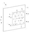
図3,4に、貫通孔4の配置を例示する。図3,4の上下方向Xは、紙面の上下を向くものとする。図3では、転写層3の面上で複数の貫通孔4が2方向(上下、左右)に等間隔で並んで複数の列と行とを成している。
図4では、任意の列T1の貫通孔4は、隣接する列T2の貫通孔4に対して上下方向にずれるよう配置されている。複数の貫通孔4は千鳥配置されている。網6は正方形状であり、上下方向Xに対して±45度の角度がつけられている。
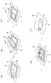
次に、図5を参照して本実施形態に係る塗装方法の手順を説明する。本実施形態に係る塗装方法は、航空機、船舶および鉄道車両等の塗装に適用できる。本実施形態では、航空機の基体表面10を対象物とした場合を説明する。
(塗装フィルム)
支持体シート2上に、塗料を印刷して転写層3を形成する。印刷方法は、公知の技術を適用できる。印刷後、塗料の溶媒を適度に揮発させて、貫通孔4が閉鎖されない程度の粘度状態にする。市販されている塗装フィルムの転写層3は、貫通孔4が閉鎖されない程度の粘度を有するため、市販品を使用することもできる。
支持体シート2上に、塗料を印刷して転写層3を形成する。印刷方法は、公知の技術を適用できる。印刷後、塗料の溶媒を適度に揮発させて、貫通孔4が閉鎖されない程度の粘度状態にする。市販されている塗装フィルムの転写層3は、貫通孔4が閉鎖されない程度の粘度を有するため、市販品を使用することもできる。
次に、転写層3に複数の貫通孔4を形成する。貫通孔4を形成する際、転写層3の面上の上下方向Xを予め定めておく。複数の貫通孔4は、所定の上下方向Xに沿って間隔をあけて並んで複数の列を成すように配置する。複数の貫通孔4は、例えば図3,4で示した配置にする。複数の貫通孔4は、図4に示すように、任意の列の貫通孔4が、隣接する列の貫通孔4に対して上下方向Xにずれるよう形成するとよい。
貫通孔4は、支持体シート2を貫通させずに、転写層3のみを貫通するよう穿孔部材(不図示)を用いて形成する。穿孔部材は、例えば、彫刻機、カッティングプロッター、レーザー加工機等である。彫刻機は、スピンドルのY軸の移動距離を転写層3の厚さに設定することで、支持体シート2を貫通させずに、転写層3のみに貫通孔4を形成することができる。支持体シート2を貫通させないことで、転写時に、押圧により支持体シートから転写層3の塗料が染み出るのを防止できる。
(前処理)
塗装前に、必要に応じて基体表面10を、清潔で乾燥した状態にする。例えば、イソプロピルアルコールを使用して基体表面10を清掃する。必要に応じて、清掃前にサンディングなどの表面処理を施してもよい。
塗装前に、必要に応じて基体表面10を、清潔で乾燥した状態にする。例えば、イソプロピルアルコールを使用して基体表面10を清掃する。必要に応じて、清掃前にサンディングなどの表面処理を施してもよい。
(マスキング)
基体表面の塗装範囲をマスキング材11で囲う(図5(A)参照)。
基体表面の塗装範囲をマスキング材11で囲う(図5(A)参照)。
(接着塗料の塗布)
基体表面10の塗装範囲に、接着塗料を塗布し、接着塗膜12を形成させる(図5(A)参照)。接着塗膜12は、粘着性を有するが、指等で触れた際に触れたものに付着しない状態のものである。接着塗料は、例えば、ポリウレタン塗料、ラッカー塗料等である。
基体表面10の塗装範囲に、接着塗料を塗布し、接着塗膜12を形成させる(図5(A)参照)。接着塗膜12は、粘着性を有するが、指等で触れた際に触れたものに付着しない状態のものである。接着塗料は、例えば、ポリウレタン塗料、ラッカー塗料等である。
(転写)
転写層3に貫通孔4を形成した塗装フィルム1を、転写層3が基体表面10に向くよう配置する。その際、転写層3の上下方向Xを、基体表面10の塗布範囲を主閲覧方向から正面視した際の目線上側と下側に揃える。
転写層3に貫通孔4を形成した塗装フィルム1を、転写層3が基体表面10に向くよう配置する。その際、転写層3の上下方向Xを、基体表面10の塗布範囲を主閲覧方向から正面視した際の目線上側と下側に揃える。
次に、塗装フィルム1を支持体シート2側から基体表面10に押圧して転写層3を基体表面10に転写する。図5(B)では、転写層3をマスキング材11で囲まれた範囲内に収まるよう位置決めして、塗装フィルム1の一端を基体表面10に固定する。固定した一端側で支持体シート2上に押圧部材13を押し付け、他端側に向けてスライドさせる。これにより、転写層3が基体表面10に転写されて装飾層5となる。一回のスライドで転写層3が基体表面に転写されていない場合は、押圧を繰り返す。押圧部材13は、スキージおよびローラ等である。
(後処理)
転写層3が基体表面10に転写されたことを確認した後、支持体シート2を装飾層5から剥離する(図5(C)参照)。次に、ローラ等の塗布部材14を用いて、転写された転写層(装飾層)5の表面に保護塗料を塗布する(図5(D)参照)。保護塗料は、装飾層5に耐久性、外観品質を付与できる材料からなる。保護塗料は、例えば、ポリウレタン塗料、ラッカー塗料等である。
転写層3が基体表面10に転写されたことを確認した後、支持体シート2を装飾層5から剥離する(図5(C)参照)。次に、ローラ等の塗布部材14を用いて、転写された転写層(装飾層)5の表面に保護塗料を塗布する(図5(D)参照)。保護塗料は、装飾層5に耐久性、外観品質を付与できる材料からなる。保護塗料は、例えば、ポリウレタン塗料、ラッカー塗料等である。
塗布した保護塗料を乾燥させて保護膜(不図示)とした後、マスキング材11を除去する(図5(E)参照)。
図6に、航空機16の基体側表面に転写された転写層(装飾層)5の様子を示す。図6において、主閲覧方向は地面に水平な方向(紙面奥行方向)、上下方向Xは重力方向に沿う方向である。図6では、複数の貫通孔4が所定の上下方向Xに沿って間隔をあけて並んで複数の列を成し、任意の列の貫通孔4が、隣接する列の貫通孔4に対して上下方向Xにずれるよう配置されている。
本実施形態では、塗装フィルム1を押圧して転写層3を転写する。その際、転写層3と基体表面10との間に巻き込まれた気泡は、貫通孔4を通って転写層3背側(支持体シート2側)に移動する。背側に移動した気泡は、支持体シート2を剥離することで大気に拡散させられる。これにより、転写層3と基体表面10との間に気泡が残留することを防止でき、転写層3と基体表面10と密着性を向上させることができる。
図1から図6では、貫通孔4の配置を明確にするために実際の縮尺とは異なる大きさで貫通孔4を表示している。直径が0.3mm以上0.7mm以下の貫通孔4は、遠目から目視で確認できるものではない。貫通孔4は、3m程度近づいた場合に、その存在を確認できるかもしれないが、図4に示すように隣接する列の貫通孔を上下方向にずらすことで、その存在を確認しにくくできる。これにより外観品質を向上させられる。転写層3が転写される基体表面10が曲面であっても同様の効果が得られる。
1 塗装フィルム
2 支持体シート
3 転写層
4 貫通孔
5 装飾層(転写層)
6 網
10 基体表面(対象物表面)
11 マスキング材
12 接着塗膜
13 押圧部材
14 塗布部材
16 航空機
2 支持体シート
3 転写層
4 貫通孔
5 装飾層(転写層)
6 網
10 基体表面(対象物表面)
11 マスキング材
12 接着塗膜
13 押圧部材
14 塗布部材
16 航空機
Claims (3)
- 支持体シート上に転写層を備えた塗装フィルムに、該転写層のみを貫通する複数の貫通孔を形成し、
前記複数の貫通孔を形成した後に、前記塗装フィルムを、前記転写層が対象物表面に向くよう配置し、
前記転写層が前記対象物表面に転写されるよう、前記塗装フィルムを支持体シート側から前記対象物表面に押圧し、
前記押圧後に、前記支持体シートを前記転写層から剥離する塗装方法。 - 前記複数の貫通孔を形成する工程において、
前記転写層の面上の上下方向を定め、
前記複数の貫通孔が前記上下方向に沿って間隔をあけて並んで複数の列を成し、任意の列の貫通孔が、隣接する列の貫通孔に対して前記上下方向にずれるよう前記複数の貫通孔を形成する請求項1に記載の塗装方法。 - 支持体シートと、
剥離可能に前記支持体シートで支持されている転写層と、
を備え、
前記転写層が、複数の貫通孔を備え、
前記複数の貫通孔が、所定の上下方向に沿って間隔をあけて並んで複数の列を成し、任意の列の貫通孔が、隣接する列の貫通孔に対して前記上下方向にずれるよう配置されている塗装フィルム。
Priority Applications (2)
| Application Number | Priority Date | Filing Date | Title |
|---|---|---|---|
| US16/348,569 US11084320B2 (en) | 2016-11-16 | 2017-10-18 | Coating method and coating film |
| JP2018551530A JP6821695B2 (ja) | 2016-11-16 | 2017-10-18 | 塗装方法および塗装フィルム |
Applications Claiming Priority (2)
| Application Number | Priority Date | Filing Date | Title |
|---|---|---|---|
| JP2016223225 | 2016-11-16 | ||
| JP2016-223225 | 2016-11-16 |
Publications (1)
| Publication Number | Publication Date |
|---|---|
| WO2018092497A1 true WO2018092497A1 (ja) | 2018-05-24 |
Family
ID=62145382
Family Applications (1)
| Application Number | Title | Priority Date | Filing Date |
|---|---|---|---|
| PCT/JP2017/037682 Ceased WO2018092497A1 (ja) | 2016-11-16 | 2017-10-18 | 塗装方法および塗装フィルム |
Country Status (3)
| Country | Link |
|---|---|
| US (1) | US11084320B2 (ja) |
| JP (1) | JP6821695B2 (ja) |
| WO (1) | WO2018092497A1 (ja) |
Citations (9)
| Publication number | Priority date | Publication date | Assignee | Title |
|---|---|---|---|---|
| JPS5248937B2 (ja) * | 1971-09-23 | 1977-12-13 | ||
| JPS57100093A (en) * | 1980-12-12 | 1982-06-22 | Zenzo Nakatsuka | Manufacture of transfer type decorative foil |
| JPH0281687A (ja) * | 1988-09-19 | 1990-03-22 | Brother Ind Ltd | 再転写シート |
| JPH0369397A (ja) * | 1989-08-09 | 1991-03-25 | Dainippon Printing Co Ltd | 透視可能な化粧スクリーンおよびその製造方法 |
| JPH0390998U (ja) * | 1989-12-28 | 1991-09-17 | ||
| JPH03236985A (ja) * | 1990-02-13 | 1991-10-22 | Brother Ind Ltd | 再転写シート |
| JP2003305997A (ja) * | 2002-04-17 | 2003-10-28 | Hakuichi:Kk | 転写シート及びその製造方法 |
| JP2017105035A (ja) * | 2015-12-08 | 2017-06-15 | キヤノンファインテック株式会社 | 転写材、記録物、それらの製造装置および製造方法 |
| JP2017105036A (ja) * | 2015-12-08 | 2017-06-15 | キヤノンファインテック株式会社 | 転写材、記録物、それらの製造装置および製造方法 |
Family Cites Families (6)
| Publication number | Priority date | Publication date | Assignee | Title |
|---|---|---|---|---|
| US4973509A (en) | 1988-09-12 | 1990-11-27 | Brother Kogyo Kabushiki Kaisha | Image-retransfer sheet |
| US5556693A (en) | 1989-12-06 | 1996-09-17 | Brother Kogyo Kabushiki Kaisha | Image-retransferable sheet for a dry image-transferring material |
| JP2612382B2 (ja) | 1991-01-25 | 1997-05-21 | 松下電工 株式会社 | 薄厚smcシートの製造方法 |
| US5609938A (en) * | 1993-06-23 | 1997-03-11 | Creative Minds Foundation, Inc. | Image display apparatus with holes for opposite side viewing |
| US5830529A (en) * | 1996-01-11 | 1998-11-03 | Ross; Gregory E. | Perimeter coating alignment |
| WO2000046043A1 (en) * | 1999-02-03 | 2000-08-10 | Contra Vision Ltd. | Partial imaging of a substrate with superimposed layers |
-
2017
- 2017-10-18 WO PCT/JP2017/037682 patent/WO2018092497A1/ja not_active Ceased
- 2017-10-18 JP JP2018551530A patent/JP6821695B2/ja not_active Expired - Fee Related
- 2017-10-18 US US16/348,569 patent/US11084320B2/en not_active Expired - Fee Related
Patent Citations (9)
| Publication number | Priority date | Publication date | Assignee | Title |
|---|---|---|---|---|
| JPS5248937B2 (ja) * | 1971-09-23 | 1977-12-13 | ||
| JPS57100093A (en) * | 1980-12-12 | 1982-06-22 | Zenzo Nakatsuka | Manufacture of transfer type decorative foil |
| JPH0281687A (ja) * | 1988-09-19 | 1990-03-22 | Brother Ind Ltd | 再転写シート |
| JPH0369397A (ja) * | 1989-08-09 | 1991-03-25 | Dainippon Printing Co Ltd | 透視可能な化粧スクリーンおよびその製造方法 |
| JPH0390998U (ja) * | 1989-12-28 | 1991-09-17 | ||
| JPH03236985A (ja) * | 1990-02-13 | 1991-10-22 | Brother Ind Ltd | 再転写シート |
| JP2003305997A (ja) * | 2002-04-17 | 2003-10-28 | Hakuichi:Kk | 転写シート及びその製造方法 |
| JP2017105035A (ja) * | 2015-12-08 | 2017-06-15 | キヤノンファインテック株式会社 | 転写材、記録物、それらの製造装置および製造方法 |
| JP2017105036A (ja) * | 2015-12-08 | 2017-06-15 | キヤノンファインテック株式会社 | 転写材、記録物、それらの製造装置および製造方法 |
Also Published As
| Publication number | Publication date |
|---|---|
| JP6821695B2 (ja) | 2021-01-27 |
| US11084320B2 (en) | 2021-08-10 |
| US20190329587A1 (en) | 2019-10-31 |
| JPWO2018092497A1 (ja) | 2019-10-17 |
Similar Documents
| Publication | Publication Date | Title |
|---|---|---|
| US11420229B2 (en) | Method and apparatus for producing a decorative surface | |
| CN105579245B (zh) | 在冲压工具上通过加设金属层制造表面结构的方法 | |
| AU2011328518B2 (en) | Method for applying a decoration to a composite wood board | |
| CN106687269A (zh) | 用于3d打印部件的修整系统 | |
| TWI658874B (zh) | 加飾於凹凸面上的加飾品之製造方法、加飾於凹凸面上的加飾品及描繪品之製造方法 | |
| JP5836426B2 (ja) | ジグソーパズルの製造方法およびジグソーパズル用袋 | |
| WO2018092497A1 (ja) | 塗装方法および塗装フィルム | |
| US10065448B2 (en) | Creation of a three dimensional liquid art on a surface by utilizing a super hydrophobic coating | |
| US1937858A (en) | Method of making index strips | |
| US9539849B2 (en) | Hydraulic transfer film, pattern film, and method of forming a hydraulic transfer film | |
| JP2011025436A (ja) | 石材の一部に彫刻され、該彫刻部分に顔料が展着された石材彫刻体 | |
| JP2011101753A (ja) | ジグソーパズル及びその製造方法 | |
| KR20190119362A (ko) | 부분 박리 문양을 형성하는 필름 또는 부분 박리 문양을 형성하는 필름이 부착된 물건의 제조장치 및 제조 방법 | |
| CN101137516B (zh) | 将装饰膜施加到支撑物的方法和制备用于所述目的的制品的方法 | |
| KR20100071277A (ko) | 홀로그램 수압 전사 필름 및 홀로그램 수압 전사품 | |
| JP2010131769A (ja) | 金属箔装飾方法 | |
| EP3600895B1 (en) | Method for creating full color heat activated transfers | |
| DE3500552C2 (ja) | ||
| JP3214791U (ja) | 装飾付き印刷物 | |
| JP2014221544A (ja) | 水転写式デカールとその製造方法 | |
| US2711039A (en) | Method of making three-dimensional objects of flat sheets | |
| GB2034251A (en) | Improvements in or Relating to Picture-Making Boards | |
| JP3194242U (ja) | 絵画 | |
| KR20170011325A (ko) | 휘어지는 판자개 | |
| JP2019055581A (ja) | 装飾付き印刷物 |
Legal Events
| Date | Code | Title | Description |
|---|---|---|---|
| 121 | Ep: the epo has been informed by wipo that ep was designated in this application |
Ref document number: 17871503 Country of ref document: EP Kind code of ref document: A1 |
|
| ENP | Entry into the national phase |
Ref document number: 2018551530 Country of ref document: JP Kind code of ref document: A |
|
| NENP | Non-entry into the national phase |
Ref country code: DE |
|
| 122 | Ep: pct application non-entry in european phase |
Ref document number: 17871503 Country of ref document: EP Kind code of ref document: A1 |