WO2018092548A1 - 積層フィルムの立体成形方法 - Google Patents
積層フィルムの立体成形方法 Download PDFInfo
- Publication number
- WO2018092548A1 WO2018092548A1 PCT/JP2017/038923 JP2017038923W WO2018092548A1 WO 2018092548 A1 WO2018092548 A1 WO 2018092548A1 JP 2017038923 W JP2017038923 W JP 2017038923W WO 2018092548 A1 WO2018092548 A1 WO 2018092548A1
- Authority
- WO
- WIPO (PCT)
- Prior art keywords
- film
- molding
- laminated film
- laminated
- anvil
- Prior art date
- Legal status (The legal status is an assumption and is not a legal conclusion. Google has not performed a legal analysis and makes no representation as to the accuracy of the status listed.)
- Ceased
Links
Images

Classifications
-
- B—PERFORMING OPERATIONS; TRANSPORTING
- B29—WORKING OF PLASTICS; WORKING OF SUBSTANCES IN A PLASTIC STATE IN GENERAL
- B29C—SHAPING OR JOINING OF PLASTICS; SHAPING OF MATERIAL IN A PLASTIC STATE, NOT OTHERWISE PROVIDED FOR; AFTER-TREATMENT OF THE SHAPED PRODUCTS, e.g. REPAIRING
- B29C43/00—Compression moulding, i.e. applying external pressure to flow the moulding material; Apparatus therefor
- B29C43/22—Compression moulding, i.e. applying external pressure to flow the moulding material; Apparatus therefor of articles of indefinite length
- B29C43/30—Making multilayered or multicoloured articles
-
- B—PERFORMING OPERATIONS; TRANSPORTING
- B29—WORKING OF PLASTICS; WORKING OF SUBSTANCES IN A PLASTIC STATE IN GENERAL
- B29C—SHAPING OR JOINING OF PLASTICS; SHAPING OF MATERIAL IN A PLASTIC STATE, NOT OTHERWISE PROVIDED FOR; AFTER-TREATMENT OF THE SHAPED PRODUCTS, e.g. REPAIRING
- B29C43/00—Compression moulding, i.e. applying external pressure to flow the moulding material; Apparatus therefor
- B29C43/32—Component parts, details or accessories; Auxiliary operations
- B29C43/36—Moulds for making articles of definite length, i.e. discrete articles
-
- B—PERFORMING OPERATIONS; TRANSPORTING
- B29—WORKING OF PLASTICS; WORKING OF SUBSTANCES IN A PLASTIC STATE IN GENERAL
- B29C—SHAPING OR JOINING OF PLASTICS; SHAPING OF MATERIAL IN A PLASTIC STATE, NOT OTHERWISE PROVIDED FOR; AFTER-TREATMENT OF THE SHAPED PRODUCTS, e.g. REPAIRING
- B29C43/00—Compression moulding, i.e. applying external pressure to flow the moulding material; Apparatus therefor
- B29C43/32—Component parts, details or accessories; Auxiliary operations
- B29C43/58—Measuring, controlling or regulating
Definitions
- the present invention relates to a method for three-dimensionally forming a laminated film, and more specifically, an overhanging portion that can form a sufficiently high overhanging portion without occurrence of wrinkles and has excellent appearance characteristics.
- the present invention relates to a three-dimensional molding method of a laminated film capable of molding a film.
- a flexible packaging body used for refilling to seal and wrap contents that have fluidity, such as liquid and powder, and transfer to another container for use. It has been practiced to form a spout and the like by three-dimensionally forming a laminated film to be extended on both outer sides. As such a three-dimensional molding method, the laminated film is preheated and then press-molded and simultaneously cooled in the mold (Patent Document 1), or the plastic film is heated and then molded while being cooled (Patent Document 2). ) Has been proposed.
- the spout cannot be formed in a state in which two laminated films are preliminarily overlapped, and a shift due to processing elongation caused by press forming occurs, and a margin for this shift is provided.
- the present applicant compression-molds a laminated film in which at least the innermost soft inner surface film and the outer surface side high-strength outer film are laminated in the thickness direction in the cold, A method for three-dimensionally forming a laminated film, characterized in that the compression-molded portion is projected outward (Patent Document 3).
- JP 2000-343603 A Japanese Patent Laid-Open No. 2001-18996 JP 2014-46655 A
- the molding height of the overhanging portion such as when increasing the flow rate of the spout or decorating the pouch with the overhanging portion. It is rare.
- it has been performed by increasing the compression load, for example, by reducing the clearance between the molding die and the anvil (base).
- the molding load is increased, the laminated film is damaged or the burden on the molding equipment is increased, so that it is not fully satisfactory in terms of productivity and economy.
- the molding height of the overhanging portion can be increased, there is a problem that wrinkles are likely to occur in the overhanging portion.
- the object of the present invention is to reduce the load on the laminated film or the molding equipment even when the molding height of the overhanging portion is increased, and to efficiently form the overhanging portion having excellent appearance characteristics. It is to provide a three-dimensional forming method of a laminated film.
- a laminated film in which at least the innermost soft inner surface film and the outer surface side high strength outer surface film are laminated is compression-molded using a molding die and an anvil, and the compression-molded portion is formed on the outer surface side.
- a method for three-dimensional forming of a laminated film to be stretched a method for three-dimensional forming of a laminated film is provided, wherein the anvil has a surface roughness (Ra) of 0.5 ⁇ m or less.
- the surface roughness (Ra) of the molding die is 1 to 5 ⁇ m; 2. Performing the compression molding cold, 3. After the laminated film is heated to a temperature equal to or lower than the Vicat softening temperature of the resin constituting the inner film of the laminated film, compression molding is performed at room temperature to a temperature equal to or lower than the Vicat softening point temperature. 4).
- the molding height of the overhanging portion formed in the laminated film is 0.1 mm or more, 5).
- the mold and the anvil are composed of rotating rolls; 6).
- the soft inner film is a heat-sealable film, and the outer film having high strength is a stretched film, Is preferred.
- the surface roughness (Ra) of the anvil is set to 0.5 ⁇ m or less so that the clearance between the molding die and the anvil is set using the same laminated film and the same molding height.
- the lamination film and the molding die can be cooled at room temperature, but the lamination film is heated to a temperature equal to or lower than the Vicat softening temperature of the resin constituting the inner surface film. Further, by performing compression molding from room temperature to a temperature equal to or lower than the softening temperature, the overhanging process can be efficiently performed with a lower molding load.
- the molding height of the overhang portion formed with the surface roughness (Ra) of the anvil being 0.5 ⁇ m or less (Examples 1 and 2) is 0.3 mm or more.
- the molding height of the bulged portion that was three-dimensionally molded under the same molding conditions except that the surface roughness (Ra) of the anvil exceeds 0.5 ⁇ m (Comparative Example 1) is 0, which is less than 0.3 mm.
- the three-dimensional molding method of the laminated film of the present invention reduces the molding load, does not damage the laminated film, and can reduce the load on the molding equipment. It is clear that there is.
- the overhanging portion that is three-dimensionally molded with the anvil surface roughness (Ra) of 0.5 ⁇ m and the molding die surface roughness (Ra) of 1 to 5 ⁇ m (Examples 3 to 6) is wrinkled, When there is no rough surface trace on the outer film surface of the laminated film and the surface roughness (Ra) of the molding die is less than 1 ⁇ m (Comparative Examples 2 and 3), wrinkles are generated in the overhanging portion, while the molding die When the surface roughness (Ra) of the mold exceeds 5 ⁇ m (Comparative Examples 4 and 5), there is a tendency that a rough surface mark is generated on the outer film surface of the laminated film, and the surface roughness (Ra) of the molding die is increased.
- the surface roughness in this invention is based on arithmetic mean roughness (Ra) based on JISB0601.
- the three-dimensional molding method of the laminated film uses a laminated film in which a soft inner film as the innermost surface and an outer surface film having a high strength on the outer surface are laminated, and compression molding is performed in the thickness direction on the portion of the laminated film to be three-dimensionally molded.
- the compressed laminated film stretches greatly so that the soft inner film is deformed and pushed out from the compressed surface, and the high-strength outer film is stretched according to the elongation of the inner film.
- the thicknesses of the inner film and the outer film are restored.
- the restoration of the soft inner film is large, but the restoration of the outer film is slight, so the strength is high.
- a phenomenon of projecting to the outer film side occurs, and the compressed portion can be projected to the outer surface side.
- FIG. 1 is a diagram illustrating an example in which a rotary processing apparatus that performs compression while rotating using a pair of processing rolls as a compression molding apparatus in the three-dimensional molding method of a laminated film of the present invention.
- This rotary processing apparatus is composed of a processing roll 12 having a molding die 11 and an anvil roll 13.
- the surface roughness of the anvil roll 13 on which the laminated film 10 contacts is 0.5 ⁇ m or less.
- Having (Ra) is an important feature.
- the processing by the molding die 11 and the anvil roll 13 is performed by point contact or line contact, so that the contact area is small and necessary as compared with the flat press processing apparatus that processes the punch and anvil described later in surface contact.
- the molding force can be easily applied, and the apparatus itself can be downsized. Moreover, it can also process continuously, conveying a film by rotation of a roll.
- the compressive load which acts on the laminated film 10 can be adjusted, and the overhang
- the surface roughness (Ra) of the anvil roll is set to 0.5 ⁇ m or less so that the clearance amount (L) can be increased even when an overhanging portion having the same molding height is formed. As a result, it is possible to reduce the compression load required for molding and reduce the damage to the laminated film and the load on the compression molding apparatus.
- the surface roughness (Ra) of the anvil roll by adjusting the surface roughness (Ra) of the anvil roll to 0.5 ⁇ m or less, preferably, the surface roughness (Ra) of the molding die of the processing roll is simultaneously in the range of 1 to 5 ⁇ m.
- the overhanging portion having a sufficient height of a molding height h of 0.1 mm or more, preferably 0.15 mm or more can be formed more efficiently. That is, by setting the surface roughness of the anvil roll and the surface roughness of the molding die within the above ranges, the outer film has a large frictional force with the molding die and the inner film has a small frictional force with the anvil roll. The shearing force generated between the inner surface film and the outer surface film of the laminated film is increased.
- this shearing force acts so as to supplement the compressive force for forming the bulged portion, so that the compressed force reduced by increasing the clearance amount (L) is efficiently applied to the laminated film.
- the surface roughness of the molding die is larger than the above range, processing traces (rough surface traces) due to the rough surface of the molding die may be formed in the overhang processing portion.
- the surface roughness of the molding die is as close to zero as possible and is like a mirror finish, the wrinkles may occur in the overhanging portion.
- the molding height h is less than 0.1 mm, the design, characters, and marks of the projecting portion are inferior and decorative, and the design cannot be improved.
- the upper limit may be determined in consideration of the basic performance as a packaged body such as the design properties, breakage and peeling, gas barrier property, water vapor barrier property, drop strength resistance, puncture resistance, etc.
- the laminated film 10 may remain at room temperature (normal temperature) without being heated.
- the Vicat softening temperature (JIS K7206) of the resin that is higher than room temperature and constitutes the inner surface film of the laminated film. Compliance
- the molding process may be cold performed at room temperature without heating the molding die 11 and the anvil roll 13, or the molding die 11 and / or the anvil roll 13 is heated to near the softening temperature of the inner film. Or between the cold and hot temperatures (warm).
- the mold 11 and / or the anvil roll 13 is heated to a temperature of 35 to 80 ° C., or the mold is heated to a temperature of 80 to 100 ° C. Any of these may be used, and cooling is performed after processing if necessary.
- compression molding is performed between a pair of rolls of a processing roll 12 having a molding die 11 and an anvil roll 13.
- a male mold may be formed at a location corresponding to the mold 11.
- the surface roughness (Ra) of the male surface contacting the laminated film of the anvil roll 13 is 0.5 ⁇ m or less.
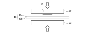
- the overhanging portion is also formed by a press method comprising a punch 22 having a processing portion 21 and an anvil 23. be able to.
- the anvil 23 (inner film side) that receives the processed portion 21 of the punch 22 may be flat or male, but the surface roughness (Ra) is 0.5 ⁇ m or less. This is important in reducing the molding load when forming an overhanging portion having a molding height h and reducing the load on the laminated film and the press molding apparatus.
- the laminated film when a stretched processed part is formed by compression molding a single laminated film composed of a soft inner film and a strong outer film, the laminated film is made so that the inner films face each other. Even when two sheets are overlapped, the overhanging portion can be formed.
- the surface roughness (Ra) of the anvil is set to 0.5 ⁇ m or less, and preferably, the surface roughness (Ra) of the molding die is set in the range of 1 to 5 ⁇ m.
- an overhanging portion having a sufficient molding height can be formed with a small molding load.
- an overhanging portion is formed only in the laminated film on the molding die side, or a stretched overhang on the outer film side on both laminated films.
- the processing part can be processed in any aspect by adjusting the compressive load acting on the laminated film. Even in this case, by adjusting the surface roughness of the anvil and, if necessary, the surface roughness of the molding die, the compression load required for molding can be reduced as compared with the prior art, and the load on the laminated film and molding apparatus is reduced. Can be reduced.
- the laminated film used in the three-dimensional molding method of the present invention uses a soft film as the inner film serving as the innermost surface and a high strength film as the outer film.
- a soft film used as the inner film in other words, a film having a large elongation, it is preferable to use a film having heat sealing properties such as a polyolefin film such as polyethylene or polypropylene.
- stretched films such as nylon and polyethylene terephthalate (hereinafter sometimes referred to as “PET”) are desirably used as the high-strength film used as the outer film.
- the thicknesses of the inner film and the outer film before the bulging process are not limited to this, but the inner film is in the range of 50 to 200 ⁇ m and the outer film is 10 to 30 ⁇ m from the viewpoint of molding processability of the bulging process part. It is particularly preferable that the inner film has a thickness of about 3 to 20 times that of the outer film. Furthermore, another layer may be formed between the inner surface film and the outer surface film as long as the effects of the present invention are not impaired, such as the above metal vapor deposition film, or the outer surface film, such as a top coat layer. . When another layer is provided on the laminated film, the total thickness of the laminated film is desirably in the range of 70 to 300 ⁇ m.
- Example 1 The surface roughness (Ra) of the molding die mounted on the processing roll is 2.7 ⁇ m, the width of the overhang processing portion (processing roll width direction): 30 mm, the length (processing roll rotation direction): 3 mm, the surface of the anvil roll The roughness (Ra) was 0.02 ⁇ m, and the set clearance L between the molding die attached to the processing roll and the anvil roll was 50 ⁇ m.
- the outer film (stretched nylon film) of the laminated film is used as the processing roll side
- the inner film linear low density polyethylene film
- the forming height h of the overhang processing portion was measured. The results are shown in Table 1.
- Example 2 Except that the surface roughness (Ra) of the anvil roll was 0.5 ⁇ m, compression molding was performed in the same manner as in Example 1, and the molding height h of the overhanging portion projecting outward was measured. The results are shown in Table 1.
- the surface roughness (Ra) of the molding die to be mounted on the work roll is set by setting the surface roughness (Ra) of the anvil roll to 0.5 ⁇ m or less.
- the molding height h of the overhanging portion projecting to the outer surface side is set to a sufficient height, so that a laminated film excellent in stereoscopic effect can be obtained.
- the surface roughness (Ra) of the molding die attached to the processing roll is 1.0 ⁇ m, the width of the overhang processing portion (processing roll width direction): 50 mm, the length (processing roll rotation direction): 3 mm, the surface of the anvil roll
- the roughness (Ra) was set to 0.5 ⁇ m, and the set clearances L: 10, 30, and 50 ⁇ m between the molding die attached to the processing roll and the anvil roll were set, respectively.
- the outer film (stretched nylon film) of the laminated film is used as the processing roll side
- the inner film linear low density polyethylene film
- the forming height h of the overhanging processed part was measured, and the presence or absence of wrinkles and rough surface marks was visually confirmed. The results are shown in Table 2.
- Example 4 Except that the surface roughness (Ra) of the molding die mounted on the processing roll was set to 2.0 ⁇ m, compression molding was performed in the same manner as in Example 3, and the molding height h of the overhanging portion projecting to the outer surface side was set. Measured and visually checked for wrinkles and rough traces. The results are shown in Table 2.
- Example 5 Except that the surface roughness (Ra) of the molding die to be mounted on the processing roll was 2.35 ⁇ m, compression molding was performed in the same manner as in Example 3, and the molding height h of the overhanging portion projecting to the outer surface side was set to Measured and visually checked for wrinkles and rough traces. The results are shown in Table 2.
- Example 6 Except that the surface roughness (Ra) of the molding die to be mounted on the processing roll was set to 5.0 ⁇ m, compression molding was performed in the same manner as in Example 3, and the molding height h of the overhanging portion projecting to the outer surface side was set. Measured and visually checked for wrinkles and rough traces. The results are shown in Table 2.
- the surface roughness (Ra) of the anvil roll is 0.5 ⁇ m or less, and the surface of the molding die to be mounted on the processing roll
- the roughness (Ra) is 1 ⁇ m or more, wrinkles in the overhanging portion projecting to the outer surface side or in the vicinity thereof are suppressed, and the surface roughness (Ra) of the molding die mounted on the processing roll is reduced.
- the thickness is 5 ⁇ m or less, a laminated film excellent in appearance characteristics in which wrinkles and rough traces are prevented can be obtained without producing rough traces on the outer film surface of the laminated film.
Landscapes
- Engineering & Computer Science (AREA)
- Mechanical Engineering (AREA)
- Bag Frames (AREA)
- Moulds For Moulding Plastics Or The Like (AREA)
- Casting Or Compression Moulding Of Plastics Or The Like (AREA)
- Laminated Bodies (AREA)
- Shaping Of Tube Ends By Bending Or Straightening (AREA)
Abstract
本発明は、少なくとも最内面の柔らかい内面フィルムと外面側の強度の高い外面フィルムとがラミネートされた積層フィルムを、成形金型及びアンビルを用いて圧縮成形し、当該圧縮成形部を外面側に張出させる積層フィルムの立体成形方法において、前記アンビルの表面粗度(Ra)が0.5μm以下であることを特徴とする。これにより、張出加工部の成形高さを大きくした場合でも、積層フィルム或いは成形設備への負担が軽減可能であり、外観特性に優れた張出加工部を効率よく成形できる。
Description
本発明は、積層フィルムの立体成形方法に関するものであり、より詳細には、充分に高さのある張出加工部をしわなどの発生なく成形可能であり、外観特性に優れた張出加工部を成形可能な積層フィルムの立体成形方法に関する。
液体や粉体等の流動性を有する内容物を密封包装し、別の容器に移し替えて使用するための詰め替え用に使用される可撓性の包装体(パウチ)には、包装体を構成する積層フィルムを両外側に張出すように立体成形して注出口等を形成することが行われている。
このような立体成形方法としては、積層フィルムを予熱した後プレス成形し、同時に型内で冷却する方法(特許文献1)や、プラスチックフィルムを加熱した後、冷却しながら成形する方法(特許文献2)が提案されている。
このような立体成形方法としては、積層フィルムを予熱した後プレス成形し、同時に型内で冷却する方法(特許文献1)や、プラスチックフィルムを加熱した後、冷却しながら成形する方法(特許文献2)が提案されている。
上記立体成形方法では、予め2枚の積層フィルムを重ね合せた状態で注出口を成形することはできず、しかもプレス成形に伴う加工伸びによるずれが生じ、このずれを見込んだマージンを設けることから、注出口の大きさに比べて小さな張出部しか成形できないという問題があった。
このような問題を解決するために、本出願人は、少なくとも最内面の柔らかい内面フィルムと外面側の強度の高い外面フィルムとがラミネートされた積層フィルムを冷間で厚み方向に圧縮成形し、当該圧縮成形部を外面側に張り出させるようにしたことを特徴とする積層フィルムの立体成形方法を提案した(特許文献3)。
本出願人による上記立体成形方法においては、加熱や冷却の必要がなく、冷間で立体成形できると共に、積層フィルムを2枚重ね合わせた状態でも両外側や一方側に張出させることができ、連続的に高速で立体成形することができるものである。
このような問題を解決するために、本出願人は、少なくとも最内面の柔らかい内面フィルムと外面側の強度の高い外面フィルムとがラミネートされた積層フィルムを冷間で厚み方向に圧縮成形し、当該圧縮成形部を外面側に張り出させるようにしたことを特徴とする積層フィルムの立体成形方法を提案した(特許文献3)。
本出願人による上記立体成形方法においては、加熱や冷却の必要がなく、冷間で立体成形できると共に、積層フィルムを2枚重ね合わせた状態でも両外側や一方側に張出させることができ、連続的に高速で立体成形することができるものである。
上述したような立体成形方法においては、注出口の流量を大きくしたり、或いは張出加工部によりパウチに装飾を施すような場合等、張出加工部の成形高さをより大きくすることが望まれている。この際、張出加工部の成形高さを大きくするために、成形金型及びアンビル(受け台)の間のクリアランスを小さくする等、圧縮荷重を大きくすることによって行われていた。
しかしながら成形荷重を大きくすると、積層フィルムにダメージを与えたり、或いは成形設備にかかる負担も大きくなることから、生産性及び経済性の点で充分満足するものではなかった。また、張出加工部の成形高さを大きくできたとしても、張出加工部にしわが発生しやすいという問題もあった。
しかしながら成形荷重を大きくすると、積層フィルムにダメージを与えたり、或いは成形設備にかかる負担も大きくなることから、生産性及び経済性の点で充分満足するものではなかった。また、張出加工部の成形高さを大きくできたとしても、張出加工部にしわが発生しやすいという問題もあった。
従って本発明の目的は、張出加工部の成形高さを大きくした場合でも、積層フィルム或いは成形設備への負荷を軽減可能であり、外観特性に優れた張出加工部を効率よく成形可能な積層フィルムの立体成形方法を提供することである。
本発明によれば、少なくとも最内面の柔らかい内面フィルムと外面側の強度の高い外面フィルムとがラミネートされた積層フィルムを、成形金型及びアンビルを用いて圧縮成形し、当該圧縮成形部を外面側に張出させる積層フィルムの立体成形方法において、前記アンビルの表面粗度(Ra)が0.5μm以下であることを特徴とする積層フィルムの立体成形方法が提供される。
本発明の積層フィルムの立体成形方法においては、
1.前記成形金型の表面粗度(Ra)が1~5μmであること、
2.前記圧縮成形を冷間で行うこと、
3.前記積層フィルムを、該積層フィルムの内面フィルムを構成する樹脂のビカット軟化温度以下の温度に加熱した後、常温乃至前記ビカット軟化点温度以下の温度で圧縮成形を行うこと、
4.前記積層フィルムに形成される張出加工部の成形高さが0.1mm以上であること、
5.前記成形金型及びアンビルが回転ロールから成ること、
6.前記柔らかい内面フィルムがヒートシール性フィルムであり、前記強度の高い外面フィルムが延伸フィルムであること、
が好適である。
1.前記成形金型の表面粗度(Ra)が1~5μmであること、
2.前記圧縮成形を冷間で行うこと、
3.前記積層フィルムを、該積層フィルムの内面フィルムを構成する樹脂のビカット軟化温度以下の温度に加熱した後、常温乃至前記ビカット軟化点温度以下の温度で圧縮成形を行うこと、
4.前記積層フィルムに形成される張出加工部の成形高さが0.1mm以上であること、
5.前記成形金型及びアンビルが回転ロールから成ること、
6.前記柔らかい内面フィルムがヒートシール性フィルムであり、前記強度の高い外面フィルムが延伸フィルムであること、
が好適である。
本発明の積層フィルムの立体成形方法においては、アンビルの表面粗度(Ra)を0.5μm以下にすることによって、成形金型及びアンビルの間のクリアランスを、同じ積層フィルムを用い且つ同じ成形高さの張出加工部を成形する場合、従来のクリアランスに比して大きくすることが可能である。その結果、成形荷重を低減することができ、積層フィルムにダメージを与えることがないと共に成形設備への負荷を小さくすることが可能になる。また成形荷重が低減される結果、加工に要するエネルギーも削減でき、コストダウンを図ることも可能になる。
さらに、アンビルの表面粗度(Ra)を上記値にすると共に、成形金型の表面粗度(Ra)を1~5μmにすることにより、充分な張出加工部の成形高さを有し、しわの発生を抑え、成形金型に接する積層フィルムの外面フィルム表面における成形金型の粗面に起因する粗面跡の発生を抑制することができ、外観特性に優れた張出加工部を成形することができる。
本発明の立体成形方法においては、積層フィルム及び成形金型の温度を室温で行う冷間で行うことができるが、積層フィルムを、内面フィルムを構成する樹脂のビカット軟化温度以下の温度に加熱し、常温から該軟化温度以下の温度で圧縮成形することにより、より低い成形荷重で効率よく張出加工を行うことができる。
さらに、アンビルの表面粗度(Ra)を上記値にすると共に、成形金型の表面粗度(Ra)を1~5μmにすることにより、充分な張出加工部の成形高さを有し、しわの発生を抑え、成形金型に接する積層フィルムの外面フィルム表面における成形金型の粗面に起因する粗面跡の発生を抑制することができ、外観特性に優れた張出加工部を成形することができる。
本発明の立体成形方法においては、積層フィルム及び成形金型の温度を室温で行う冷間で行うことができるが、積層フィルムを、内面フィルムを構成する樹脂のビカット軟化温度以下の温度に加熱し、常温から該軟化温度以下の温度で圧縮成形することにより、より低い成形荷重で効率よく張出加工を行うことができる。
本発明の上述した作用効果は、後述する実施例の結果からも明らかである。
すなわち、成形金型及びアンビルの間のクリアランスが一定の条件下で、アンビルの表面粗度(Ra)を0.5μm以下(実施例1、2)として形成した張出加工部の成形高さは0.3mm以上である。これに対して、アンビルの表面粗度(Ra)が0.5μmを超える(比較例1)以外は同様の成形条件で立体成形された張出加工部の成形高さは0.3mm未満の0.2mmと本発明に比して低く、本発明の積層フィルムの立体成形方法が、成形荷重が低減されて積層フィルムにダメージを与えることがなく、成形設備への負荷を小さくすることが可能であることが明らかである。
また、アンビルの表面粗度(Ra)を0.5μmとし、成形金型の表面粗度(Ra)を1~5μm(実施例3~6)として立体成形された張出加工部は、しわ、積層フィルムの外面フィルム表面に粗面跡の発生がなく、成形金型の表面粗度(Ra)を1μm未満(比較例2、3)とすると張出加工部にしわが発生し、一方、成形金型の表面粗度(Ra)が5μmを超える(比較例4、5)と、積層フィルムの外面フィルム表面に粗面跡が発生する傾向がみられ、成形金型の表面粗度(Ra)を1~5μmとすることにより外観適性に優れた積層フィルムとなることが明らかである。
すなわち、成形金型及びアンビルの間のクリアランスが一定の条件下で、アンビルの表面粗度(Ra)を0.5μm以下(実施例1、2)として形成した張出加工部の成形高さは0.3mm以上である。これに対して、アンビルの表面粗度(Ra)が0.5μmを超える(比較例1)以外は同様の成形条件で立体成形された張出加工部の成形高さは0.3mm未満の0.2mmと本発明に比して低く、本発明の積層フィルムの立体成形方法が、成形荷重が低減されて積層フィルムにダメージを与えることがなく、成形設備への負荷を小さくすることが可能であることが明らかである。
また、アンビルの表面粗度(Ra)を0.5μmとし、成形金型の表面粗度(Ra)を1~5μm(実施例3~6)として立体成形された張出加工部は、しわ、積層フィルムの外面フィルム表面に粗面跡の発生がなく、成形金型の表面粗度(Ra)を1μm未満(比較例2、3)とすると張出加工部にしわが発生し、一方、成形金型の表面粗度(Ra)が5μmを超える(比較例4、5)と、積層フィルムの外面フィルム表面に粗面跡が発生する傾向がみられ、成形金型の表面粗度(Ra)を1~5μmとすることにより外観適性に優れた積層フィルムとなることが明らかである。
[立体成形方法]
本発明の積層フィルムの立体成形方法は、アンビルのフィルムの接触する表面の表面粗度(Ra)が0.5μm以下(Ra=0の鏡面の場合を含む)である点を除けば、従来公知の積層フィルムの立体成形方法と同様に行うことができる。尚、本発明における表面粗度は、JIS B0601に準拠した算術平均粗さ(Ra)によるものである。
積層フィルムの立体成形方法は、最内面となる柔らかい内面フィルムと外面側の強度の高い外面フィルムとが少なくともラミネートされた積層フィルムを用い、この積層フィルムの立体成形したい部位を、厚み方向に圧縮成形することにより行う。圧縮された積層フィルムは、柔らかい内面フィルムが変形して圧縮された面から押し出されるように大きく伸びると共に、強度の高い外面フィルムは内面フィルムの伸びに応じて伸ばされる。次いで圧縮した部分の圧力を解放することにより、内面フィルム及び外面フィルムの厚みが復元するが、その際、柔らかい内面フィルムの復元は大きいが、外面フィルムの復元はわずかであることから、強度の高い外面フィルム側に張出す現象が生じて、圧縮された部分を外面側に張り出すことが可能になる。
本発明の積層フィルムの立体成形方法は、アンビルのフィルムの接触する表面の表面粗度(Ra)が0.5μm以下(Ra=0の鏡面の場合を含む)である点を除けば、従来公知の積層フィルムの立体成形方法と同様に行うことができる。尚、本発明における表面粗度は、JIS B0601に準拠した算術平均粗さ(Ra)によるものである。
積層フィルムの立体成形方法は、最内面となる柔らかい内面フィルムと外面側の強度の高い外面フィルムとが少なくともラミネートされた積層フィルムを用い、この積層フィルムの立体成形したい部位を、厚み方向に圧縮成形することにより行う。圧縮された積層フィルムは、柔らかい内面フィルムが変形して圧縮された面から押し出されるように大きく伸びると共に、強度の高い外面フィルムは内面フィルムの伸びに応じて伸ばされる。次いで圧縮した部分の圧力を解放することにより、内面フィルム及び外面フィルムの厚みが復元するが、その際、柔らかい内面フィルムの復元は大きいが、外面フィルムの復元はわずかであることから、強度の高い外面フィルム側に張出す現象が生じて、圧縮された部分を外面側に張り出すことが可能になる。
図1は、本発明の積層フィルムの立体成形方法において、圧縮成形装置として一対の加工ロールを用いて回転しながら圧縮するロータリー加工装置を用いた例を説明する図である。
このロータリー加工装置は、成形金型11を有する加工ロール12及びアンビルロール13から成っており、本発明においては、このアンビルロール13の積層フィルム10が接触する表面が0.5μm以下の表面粗度(Ra)を有していることが重要な特徴である。
ロータリー加工装置において成形金型11とアンビルロール13による加工は点接触又は線接触でなされることから、後述するパンチとアンビルを面接触させて加工する平面プレス加工装置に比べ接触面積が小さく、必要な成形力を簡単に加えることができると共に、装置自体を小型化することもできる。またロールの回転により、フィルムを搬送しながら連続的に加工することもできる。
このロータリー加工装置は、成形金型11を有する加工ロール12及びアンビルロール13から成っており、本発明においては、このアンビルロール13の積層フィルム10が接触する表面が0.5μm以下の表面粗度(Ra)を有していることが重要な特徴である。
ロータリー加工装置において成形金型11とアンビルロール13による加工は点接触又は線接触でなされることから、後述するパンチとアンビルを面接触させて加工する平面プレス加工装置に比べ接触面積が小さく、必要な成形力を簡単に加えることができると共に、装置自体を小型化することもできる。またロールの回転により、フィルムを搬送しながら連続的に加工することもできる。
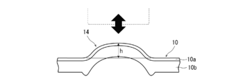
このロータリー加工装置を用いた立体成形方法においては、内面フィルム10b及び外面フィルム10aから成る積層フィルム10の厚みに対する、加工ロール12の成形金型11とアンビルロール13間の距離(クリアランス量L)を調整することにより、積層フィルム10に作用する圧縮荷重を調整することができ、図3に示す所望の成形高さhを有する張出加工部14を外面側に張出すことができる。しかしながら、本発明においては更に、アンビルロールの表面粗度(Ra)を0.5μm以下とすることにより、同じ成形高さの張出加工部を形成する場合でもクリアランス量(L)を大きくすることができ、その結果、成形に要する圧縮荷重を軽減して積層フィルムのダメージや圧縮成形装置への負荷を低減することが可能になる。
本発明においては、アンビルロールの表面粗度(Ra)を0.5μm以下に調整することによって、好適には、それと同時に加工ロールの成形金型の表面粗度(Ra)を1~5μmの範囲に調整することによって、成形高さhが0.1mm以上、好ましくは0.15mm以上、と充分な高さがある張出加工部をより効率よく形成することができる。すなわち、アンビルロールの表面粗度及び成形金型の表面粗度を上記範囲にすることにより、外側フィルムでは成形金型との摩擦力が大きく、内面フィルムではアンビルロールとの摩擦力が小さいことから、積層フィルムの内面フィルムと外面フィルムの間に生じる剪断力が大きくなる。その結果、この剪断力が張出加工部を形成するための圧縮力を補うように作用することから、クリアランス量(L)を大きくすることによって低減された圧縮力を効率よく積層フィルムに作用させることができ、張出加工部を効率よく形成することが可能になる。尚、上記範囲よりも成形金型の表面粗度が大きい場合には、成形金型の粗面に起因する加工痕(粗面跡)が張出加工部に形成されてしまうおそれがあり、一方上記範囲よりも成形金型の表面粗度が可及的にゼロに近く、鏡面仕上げのようになっている場合には、張出加工部にしわが発生するおそれがある。
なお、成形高さhが0.1mm未満であると張出加工部の図柄、文字、マークの明瞭さ、装飾性が劣り、意匠性を向上させることが出来ない。一方、上限は、前述した張出加工部の意匠性、破断や剥離、ガスバリヤー性や水蒸気バリヤー性、落下強度耐性、突き刺し耐性などの包装体としての基本性能を考慮して決定すれば良い。
なお、成形高さhが0.1mm未満であると張出加工部の図柄、文字、マークの明瞭さ、装飾性が劣り、意匠性を向上させることが出来ない。一方、上限は、前述した張出加工部の意匠性、破断や剥離、ガスバリヤー性や水蒸気バリヤー性、落下強度耐性、突き刺し耐性などの包装体としての基本性能を考慮して決定すれば良い。
成形加工に際して、積層フィルム10は、加熱することなく室温(常温)の状態のままでもよいが、好適には、室温よりも高く且つ積層フィルムの内面フィルムを構成する樹脂のビカット軟化温度(JIS K7206準拠)以下の温度に加熱されていることが望ましい。
また成形加工は、成形金型11、アンビルロール13を加熱することなく室温で行う冷間であってもよいし、成形金型11及び/又はアンビルロール13を内面フィルムの軟化温度近傍まで加熱して行う熱間、或いは冷間と熱間の中間の温度域(温間)で行ってもよい。
例えば、内面フィルムがポリエチレンの場合には、成形金型11及び/又はアンビルロール13を35~80℃の温度に加熱する温間、或いは成形金型を80~100℃の温度に加熱する熱間のいずれであってもよく、必要により加工後冷却を行う。
また成形加工は、成形金型11、アンビルロール13を加熱することなく室温で行う冷間であってもよいし、成形金型11及び/又はアンビルロール13を内面フィルムの軟化温度近傍まで加熱して行う熱間、或いは冷間と熱間の中間の温度域(温間)で行ってもよい。
例えば、内面フィルムがポリエチレンの場合には、成形金型11及び/又はアンビルロール13を35~80℃の温度に加熱する温間、或いは成形金型を80~100℃の温度に加熱する熱間のいずれであってもよく、必要により加工後冷却を行う。
図1に示した具体例においては、成形金型11を有する加工ロール12とアンビルロール13との一対のロール間で圧縮成形を行っているが、これに限定されず、アンビルロール13の成形金型11に対応する箇所に雄型が形成されていてもよい。この場合には、アンビルロール13の積層フィルムに接触する雄型表面の表面粗度(Ra)が0.5μm以下であることが重要である。
また図1に示した一対のロール間で圧縮成形するロール方式以外にも、図2に示すように、加工部21を有するパンチ22とアンビル23から成るプレス方式によっても張出加工部を形成することができる。この場合もパンチ22の加工部21を受けるアンビル23(内面フィルム側)は平板状或いは雄型の何れであってもよいが、表面粗度(Ra)が0.5μm以下であることが、同一成形高さhの張出加工部を形成する場合の成形荷重を低減し、積層フィルムやプレス成形装置への負荷を軽減する上で重要である。
また図1に示した一対のロール間で圧縮成形するロール方式以外にも、図2に示すように、加工部21を有するパンチ22とアンビル23から成るプレス方式によっても張出加工部を形成することができる。この場合もパンチ22の加工部21を受けるアンビル23(内面フィルム側)は平板状或いは雄型の何れであってもよいが、表面粗度(Ra)が0.5μm以下であることが、同一成形高さhの張出加工部を形成する場合の成形荷重を低減し、積層フィルムやプレス成形装置への負荷を軽減する上で重要である。
本発明の立体成形方法においては、柔らかい内面フィルムと強度の高い外面フィルムから成る積層フィルム1枚を圧縮成形して張出加工部を形成する場合は勿論、内面フィルム同士が対向するように積層フィルム2枚を重ね合せた場合にも、張出加工部を形成することができる。
積層フィルム1枚の場合は、アンビルの表面粗度(Ra)を0.5μm以下とし、好適には、成形金型の表面粗度(Ra)を1~5μmの範囲とすることにより、上述したとおり、充分な成形高さのある張出加工部を少ない成形荷重で形成することができる。
一方、上記のように積層フィルムを2枚重ね合わせた場合には、成形金型側の積層フィルムのみに張出加工部が形成される態様、或いは両方の積層フィルムに外面フィルム側に張出した張出加工部が形成される態様があるが、積層フィルムに作用する圧縮荷重を調整することにより何れの態様にも加工可能である。この場合でも、アンビルの表面粗度、更に必要により成形金型の表面粗度を調整することによって、従来技術に比して成形に要する圧縮荷重を低減でき、積層フィルムや成形装置への負荷を軽減することができる。
積層フィルム1枚の場合は、アンビルの表面粗度(Ra)を0.5μm以下とし、好適には、成形金型の表面粗度(Ra)を1~5μmの範囲とすることにより、上述したとおり、充分な成形高さのある張出加工部を少ない成形荷重で形成することができる。
一方、上記のように積層フィルムを2枚重ね合わせた場合には、成形金型側の積層フィルムのみに張出加工部が形成される態様、或いは両方の積層フィルムに外面フィルム側に張出した張出加工部が形成される態様があるが、積層フィルムに作用する圧縮荷重を調整することにより何れの態様にも加工可能である。この場合でも、アンビルの表面粗度、更に必要により成形金型の表面粗度を調整することによって、従来技術に比して成形に要する圧縮荷重を低減でき、積層フィルムや成形装置への負荷を軽減することができる。
[積層フィルム]
本発明の立体成形方法に用いられる積層フィルムは、前述したとおり、最内面となる内面フィルムとして柔らかいフィルム、外面フィルムとして強度の高いフィルムを用いる。
内面フィルムとして用いる柔らかいフィルム、言い換えれば伸びの大きいフィルムとしては、ポリエチレン、ポリプロピレン等のポリオレフィンフィルム等のヒートシール性を有するフィルムを用いることが好ましい。一方外面フィルムとして用いる強度の高いフィルムとしては、ナイロン、ポリエチレンテレフタレート(以下、「PET」ということがある)等の延伸フィルムを用いることが望ましい。
具体的には、これに限定されないが、内面/外面の順で、
ポリエチレンフィルム/延伸ナイロンフィルム、
ポリエチレンフィルム/延伸PETフィルム、
ポリエチレンフィルム/延伸ナイロンフィルム/延伸PETフィルム、
ポリエチレンフィルム/延伸PETフィルム/延伸ナイロンフィルム、
ポリエチレンフィルム/延伸PETフィルム/延伸PETフィルム、
ポリエチレンフィルム/アルミ蒸着延伸ナイロンフィルム/延伸PETフィルム、
ポリエチレンフィルム/アルミ蒸着延伸PETフィルム/延伸ナイロンフィルム、
ポリエチレンフィルム/アルミ蒸着延伸PETフィルム/延伸PETフィルム、
ポリプロプレンフィルム/延伸ナイロンフィルム、
ポリプロピレンフィルム/延伸PETフィルム、
ポリプロピレンフィルム/延伸ナイロンフィルム/延伸PETフィルム、
ポリプロピレンフィルム/延伸PETフィルム/延伸ナイロンフィルム、
ポリプロピレンフィルム/延伸PETフィルム/延伸PETフィルム、
ポリプロピレンフィルム/アルミ蒸着延伸ナイロンフィルム/延伸PETフィルム、
ポリプロピレンフィルム/アルミ蒸着延伸PETフィルム/延伸ナイロンフィルム、
ポリプロピレンフィルム/アルミ蒸着延伸PETフィルム/延伸PETフィルム、
等を好適に使用できる。
本発明の立体成形方法に用いられる積層フィルムは、前述したとおり、最内面となる内面フィルムとして柔らかいフィルム、外面フィルムとして強度の高いフィルムを用いる。
内面フィルムとして用いる柔らかいフィルム、言い換えれば伸びの大きいフィルムとしては、ポリエチレン、ポリプロピレン等のポリオレフィンフィルム等のヒートシール性を有するフィルムを用いることが好ましい。一方外面フィルムとして用いる強度の高いフィルムとしては、ナイロン、ポリエチレンテレフタレート(以下、「PET」ということがある)等の延伸フィルムを用いることが望ましい。
具体的には、これに限定されないが、内面/外面の順で、
ポリエチレンフィルム/延伸ナイロンフィルム、
ポリエチレンフィルム/延伸PETフィルム、
ポリエチレンフィルム/延伸ナイロンフィルム/延伸PETフィルム、
ポリエチレンフィルム/延伸PETフィルム/延伸ナイロンフィルム、
ポリエチレンフィルム/延伸PETフィルム/延伸PETフィルム、
ポリエチレンフィルム/アルミ蒸着延伸ナイロンフィルム/延伸PETフィルム、
ポリエチレンフィルム/アルミ蒸着延伸PETフィルム/延伸ナイロンフィルム、
ポリエチレンフィルム/アルミ蒸着延伸PETフィルム/延伸PETフィルム、
ポリプロプレンフィルム/延伸ナイロンフィルム、
ポリプロピレンフィルム/延伸PETフィルム、
ポリプロピレンフィルム/延伸ナイロンフィルム/延伸PETフィルム、
ポリプロピレンフィルム/延伸PETフィルム/延伸ナイロンフィルム、
ポリプロピレンフィルム/延伸PETフィルム/延伸PETフィルム、
ポリプロピレンフィルム/アルミ蒸着延伸ナイロンフィルム/延伸PETフィルム、
ポリプロピレンフィルム/アルミ蒸着延伸PETフィルム/延伸ナイロンフィルム、
ポリプロピレンフィルム/アルミ蒸着延伸PETフィルム/延伸PETフィルム、
等を好適に使用できる。
張出加工前における内面フィルム及び外面フィルムの厚みは、これに限定されないが、張出加工部の成形加工性の点から、内面フィルムが50~200μmの範囲にあり、外面フィルムが10~30μmの範囲にあり、内面フィルムが外面フィルムの3~20倍程度の厚みを有することが特に好適である。
更に、内面フィルムと外面フィルムの間には、上記金属蒸着フィルム等、或いは外面フィルムの外側にはトップコート層等、本発明の効果を損なわない範囲でさらに他の層が形成されていてもよい。
積層フィルムに、更に他の層を設ける場合には、積層フィルムの総厚みが70~300μmの範囲にあることが望ましい。
更に、内面フィルムと外面フィルムの間には、上記金属蒸着フィルム等、或いは外面フィルムの外側にはトップコート層等、本発明の効果を損なわない範囲でさらに他の層が形成されていてもよい。
積層フィルムに、更に他の層を設ける場合には、積層フィルムの総厚みが70~300μmの範囲にあることが望ましい。
[条件]
1.積層フィルム
内面から線状低密度ポリエチレンフィルム(120μm)/ウレタン系接着剤(4μm)/アルミ蒸着延伸PETフィルム(12μm)/ウレタン系接着剤(4μm)/延伸ナイロンフィルム(15μm)。総厚み:155μmの積層フィルム。
2.回転ロール加工装置
(1)加工ロールとアンビルロールの直径:130mm。
(2)成形速度:0.8m/sec(120rpm)。
3.評価
(1)張出加工部の成形高さh
積層フィルムの外面側に張り出し形成された張出加工部の加工ロール回転方向の横断面における成形高さhを表面形状測定器で測定。
(2)しわ、粗面跡の確認
しわ:積層フィルムの外面側に張り出し形成された張出加工部、或いはその近傍のしわを目視で確認。
粗面跡:積層フィルムの外面側に張り出し形成された張出加工部における外面フィルムと内面フィルムの表面の粗面跡を目視で確認。
○:発生なし、△:多少あり、×:多数あり。
1.積層フィルム
内面から線状低密度ポリエチレンフィルム(120μm)/ウレタン系接着剤(4μm)/アルミ蒸着延伸PETフィルム(12μm)/ウレタン系接着剤(4μm)/延伸ナイロンフィルム(15μm)。総厚み:155μmの積層フィルム。
2.回転ロール加工装置
(1)加工ロールとアンビルロールの直径:130mm。
(2)成形速度:0.8m/sec(120rpm)。
3.評価
(1)張出加工部の成形高さh
積層フィルムの外面側に張り出し形成された張出加工部の加工ロール回転方向の横断面における成形高さhを表面形状測定器で測定。
(2)しわ、粗面跡の確認
しわ:積層フィルムの外面側に張り出し形成された張出加工部、或いはその近傍のしわを目視で確認。
粗面跡:積層フィルムの外面側に張り出し形成された張出加工部における外面フィルムと内面フィルムの表面の粗面跡を目視で確認。
○:発生なし、△:多少あり、×:多数あり。
(実施例1)
加工ロールに装着する成形金型の表面粗度(Ra)を2.7μm、張出加工部の巾(加工ロール幅方向):30mm、長さ(加工ロール回転方向):3mm、アンビルロールの表面粗度(Ra)を0.02μm、加工ロールに装着した成形金型とアンビルロールとの設定クリアランスL:50μmとした。次いで、積層フィルムの外面フィルム(延伸ナイロンフィルム)を加工ロール側、内面フィルム(線状低密度ポリエチレンフィルム)をアンビルロール側として両ロール間に供給して圧縮成形を冷間で行い、外面側に張り出した張出加工部の成形高さhを測定した。その結果を表1に示す。
加工ロールに装着する成形金型の表面粗度(Ra)を2.7μm、張出加工部の巾(加工ロール幅方向):30mm、長さ(加工ロール回転方向):3mm、アンビルロールの表面粗度(Ra)を0.02μm、加工ロールに装着した成形金型とアンビルロールとの設定クリアランスL:50μmとした。次いで、積層フィルムの外面フィルム(延伸ナイロンフィルム)を加工ロール側、内面フィルム(線状低密度ポリエチレンフィルム)をアンビルロール側として両ロール間に供給して圧縮成形を冷間で行い、外面側に張り出した張出加工部の成形高さhを測定した。その結果を表1に示す。
(実施例2)
アンビルロールの表面粗度(Ra)を0.5μmとした以外は、実施例1と同様に圧縮成形を行い、外面側に張り出した張出加工部の成形高さhを測定した。その結果を表1に示す。
アンビルロールの表面粗度(Ra)を0.5μmとした以外は、実施例1と同様に圧縮成形を行い、外面側に張り出した張出加工部の成形高さhを測定した。その結果を表1に示す。
(比較例1)
アンビルロールの表面粗度(Ra)を1.0μmとした以外は、実施例1と同様に圧縮成形を行い、外面側に張り出した張出加工部の成形高さhを測定した。その結果を表1に示す。
アンビルロールの表面粗度(Ra)を1.0μmとした以外は、実施例1と同様に圧縮成形を行い、外面側に張り出した張出加工部の成形高さhを測定した。その結果を表1に示す。

上述した実施例1、2、比較例1、表1から、アンビルロールの表面粗度(Ra)を0.5μm以下とすることにより、加工ロールに装着する成形金型の表面粗度(Ra)と設定クリアランスLを同一とした条件において、外面側に張り出す張出加工部の成形高さhを十分な高さとし、立体感に優れた積層フィルムを得ることができる。
この結果、同じ積層フィルムを用い、且つ同じ成形高さの張出加工部を成形する場合にクリアランスを大きくすることが可能となり、成形荷重が低減され、積層フィルムにダメージを与えることがなく、また、成形設備への負荷を小さくすることが可能になることが判る。
この結果、同じ積層フィルムを用い、且つ同じ成形高さの張出加工部を成形する場合にクリアランスを大きくすることが可能となり、成形荷重が低減され、積層フィルムにダメージを与えることがなく、また、成形設備への負荷を小さくすることが可能になることが判る。
(実施例3)
加工ロールに装着する成形金型の表面粗度(Ra)を1.0μm、張出加工部の巾(加工ロール幅方向):50mm、長さ(加工ロール回転方向):3mm、アンビルロールの表面粗度(Ra)を0.5μm、加工ロールに装着した成形金型とアンビルロールとの設定クリアランスL:10、30、50μmにそれぞれ設定した。次いで、積層フィルムの外面フィルム(延伸ナイロンフィルム)を加工ロール側、内面フィルム(線状低密度ポリエチレンフィルム)をアンビルロール側として両ロール間に供給して圧縮成形を冷間で行い、外面側に張り出した張出加工部の成形高さhを測定し、しわ、粗面跡の有無を目視で確認した。その結果を表2に示す。
加工ロールに装着する成形金型の表面粗度(Ra)を1.0μm、張出加工部の巾(加工ロール幅方向):50mm、長さ(加工ロール回転方向):3mm、アンビルロールの表面粗度(Ra)を0.5μm、加工ロールに装着した成形金型とアンビルロールとの設定クリアランスL:10、30、50μmにそれぞれ設定した。次いで、積層フィルムの外面フィルム(延伸ナイロンフィルム)を加工ロール側、内面フィルム(線状低密度ポリエチレンフィルム)をアンビルロール側として両ロール間に供給して圧縮成形を冷間で行い、外面側に張り出した張出加工部の成形高さhを測定し、しわ、粗面跡の有無を目視で確認した。その結果を表2に示す。
(実施例4)
加工ロールに装着する成形金型の表面粗度(Ra)を2.0μmとした以外は、実施例3と同様に圧縮成形を行い、外面側に張り出した張出加工部の成形高さhを測定し、しわ、粗面跡の有無を目視で確認した。その結果を表2に示す。
加工ロールに装着する成形金型の表面粗度(Ra)を2.0μmとした以外は、実施例3と同様に圧縮成形を行い、外面側に張り出した張出加工部の成形高さhを測定し、しわ、粗面跡の有無を目視で確認した。その結果を表2に示す。
(実施例5)
加工ロールに装着する成形金型の表面粗度(Ra)を2.35μmとした以外は、実施例3と同様に圧縮成形を行い、外面側に張り出した張出加工部の成形高さhを測定し、しわ、粗面跡の有無を目視で確認した。その結果を表2に示す。
加工ロールに装着する成形金型の表面粗度(Ra)を2.35μmとした以外は、実施例3と同様に圧縮成形を行い、外面側に張り出した張出加工部の成形高さhを測定し、しわ、粗面跡の有無を目視で確認した。その結果を表2に示す。
(実施例6)
加工ロールに装着する成形金型の表面粗度(Ra)を5.0μmとした以外は、実施例3と同様に圧縮成形を行い、外面側に張り出した張出加工部の成形高さhを測定し、しわ、粗面跡の有無を目視で確認した。その結果を表2に示す。
加工ロールに装着する成形金型の表面粗度(Ra)を5.0μmとした以外は、実施例3と同様に圧縮成形を行い、外面側に張り出した張出加工部の成形高さhを測定し、しわ、粗面跡の有無を目視で確認した。その結果を表2に示す。
(比較例2)
加工ロールに装着する成形金型の表面粗度(Ra)を0.01μmとした以外は、実施例3と同様に圧縮成形を行い、外面側に張り出した張出加工部の成形高さhを測定し、しわ、粗面跡の有無を目視で確認した。その結果を表2に示す。
加工ロールに装着する成形金型の表面粗度(Ra)を0.01μmとした以外は、実施例3と同様に圧縮成形を行い、外面側に張り出した張出加工部の成形高さhを測定し、しわ、粗面跡の有無を目視で確認した。その結果を表2に示す。
(比較例3)
加工ロールに装着する成形金型の表面粗度(Ra)を0.5μmとした以外は、実施例3と同様に圧縮成形を行い、外面側に張り出した張出加工部の成形高さhを測定し、しわ、粗面跡の有無を目視で確認した。その結果を表2に示す。
加工ロールに装着する成形金型の表面粗度(Ra)を0.5μmとした以外は、実施例3と同様に圧縮成形を行い、外面側に張り出した張出加工部の成形高さhを測定し、しわ、粗面跡の有無を目視で確認した。その結果を表2に示す。
(比較例4)
加工ロールに装着する成形金型の表面粗度(Ra)を6.0μmとした以外は、実施例3と同様に圧縮成形を行い、外面側に張り出した張出加工部の成形高さhを測定し、しわ、粗面跡の有無を目視で確認した。その結果を表2に示す。
加工ロールに装着する成形金型の表面粗度(Ra)を6.0μmとした以外は、実施例3と同様に圧縮成形を行い、外面側に張り出した張出加工部の成形高さhを測定し、しわ、粗面跡の有無を目視で確認した。その結果を表2に示す。
(比較例5)
加工ロールに装着する成形金型の表面粗度(Ra)を8.0μmとした以外は、実施例3と同様に圧縮成形を行い、外面側に張り出した張出加工部の成形高さhを測定し、しわ、粗面跡の有無を目視で確認した。その結果を表2に示す。
加工ロールに装着する成形金型の表面粗度(Ra)を8.0μmとした以外は、実施例3と同様に圧縮成形を行い、外面側に張り出した張出加工部の成形高さhを測定し、しわ、粗面跡の有無を目視で確認した。その結果を表2に示す。

上述した実施例3~6、比較例2~5、表2から、各設定クリアランスLにおいて、アンビルロールの表面粗度(Ra)を0.5μm以下とし、加工ロールに装着する成形金型の表面粗度(Ra)を1μm以上とすることにより、外面側に張り出す張出加工部、或いはその近傍のしわが抑制され、また、加工ロールに装着する成形金型の表面粗度(Ra)を5μm以下とすることにより、積層フィルムの外面フィルム表面に粗面跡を生じることなく、しわ、粗面跡が防止された外観特性に優れた積層フィルムが得られることが判る。
また、前記した加工ロールに装着する成形金型の表面粗度(Ra)は、アンビルロールの表面粗度(Ra)よりも粗くするのが好ましいことが判る。
また、前記した加工ロールに装着する成形金型の表面粗度(Ra)は、アンビルロールの表面粗度(Ra)よりも粗くするのが好ましいことが判る。
10 積層フィルム、11 成形金型、12 加工ロール、13 アンビルロール、h 張出加工部の成形高さ、L 成形金型とアンビルロールのクリアランス。
Claims (7)
- 少なくとも最内面の柔らかい内面フィルムと外面側の強度の高い外面フィルムとがラミネートされた積層フィルムを、成形金型及びアンビルを用いて圧縮成形し、当該圧縮成形部を外面側に張出させる積層フィルムの立体成形方法において、
前記アンビルの表面粗度(Ra)が0.5μm以下であることを特徴とする積層フィルムの立体成形方法。 - 前記成形金型の表面粗度(Ra)が1~5μmである請求項1に記載の積層フィルムの立体成形方法。
- 前記圧縮成形を冷間で行う請求項1または2に記載の積層フィルムの立体成形方法。
- 前記積層フィルムを、該積層フィルムの内面フィルムを構成する樹脂のビカット軟化温度以下の温度に加熱した後、常温乃至前記ビカット軟化点温度以下の温度で圧縮成形を行う請求項1~3の何れかに記載の積層フィルムの立体成形方法。
- 前記積層フィルムに形成される張出加工部の成形高さが0.1mm以上である請求項1~4の何れかに記載の積層フィルムの立体成形方法。
- 前記成形金型及びアンビルが回転ロールから成る請求項1~5の何れかに記載の積層フィルムの立体成形方法。
- 前記柔らかい内面フィルムがヒートシール性フィルムであり、前記強度の高い外面フィルムが延伸フィルムである請求項1~6の何れかに記載の積層フィルムの立体成形方法。
Priority Applications (1)
| Application Number | Priority Date | Filing Date | Title |
|---|---|---|---|
| CN201780054688.3A CN109689331B (zh) | 2016-11-17 | 2017-10-27 | 层叠薄膜的立体成形方法 |
Applications Claiming Priority (2)
| Application Number | Priority Date | Filing Date | Title |
|---|---|---|---|
| JP2016224130A JP6358311B2 (ja) | 2016-11-17 | 2016-11-17 | 積層フィルムの立体成形方法 |
| JP2016-224130 | 2016-11-17 |
Publications (1)
| Publication Number | Publication Date |
|---|---|
| WO2018092548A1 true WO2018092548A1 (ja) | 2018-05-24 |
Family
ID=62146219
Family Applications (1)
| Application Number | Title | Priority Date | Filing Date |
|---|---|---|---|
| PCT/JP2017/038923 Ceased WO2018092548A1 (ja) | 2016-11-17 | 2017-10-27 | 積層フィルムの立体成形方法 |
Country Status (3)
| Country | Link |
|---|---|
| JP (1) | JP6358311B2 (ja) |
| CN (1) | CN109689331B (ja) |
| WO (1) | WO2018092548A1 (ja) |
Citations (4)
| Publication number | Priority date | Publication date | Assignee | Title |
|---|---|---|---|---|
| JP2014046655A (ja) * | 2012-09-04 | 2014-03-17 | Toyo Seikan Kaisha Ltd | 積層フィルムの立体成形方法およびその装置 |
| WO2017022527A1 (ja) * | 2015-08-06 | 2017-02-09 | 東洋製罐株式会社 | 装飾積層フィルム、及びこの装飾積層フィルムを有する袋状容器並びにシール材 |
| WO2017104340A1 (ja) * | 2015-12-15 | 2017-06-22 | 東洋製罐株式会社 | 包装体 |
| WO2017119231A1 (ja) * | 2016-01-05 | 2017-07-13 | 東洋製罐株式会社 | 樹脂製包装材の立体成形方法及び樹脂製包装材 |
Family Cites Families (5)
| Publication number | Priority date | Publication date | Assignee | Title |
|---|---|---|---|---|
| JPS60255416A (ja) * | 1984-06-01 | 1985-12-17 | Mitsui Toatsu Chem Inc | 凹凸の大きいエンボス模様つき熱可塑性樹脂シ−トの製造方法 |
| US6638602B2 (en) * | 2000-09-04 | 2003-10-28 | Asahi Kasei Kabushiki Kaisha | Adhesive wrapping film |
| US6811530B2 (en) * | 2003-03-06 | 2004-11-02 | Toray Plastics America, Inc. | Bag manufacturing former laminated films |
| EP2218579A1 (de) * | 2009-02-13 | 2010-08-18 | Bayer MaterialScience AG | Verbessertes Verfahren zur Herstellung eines laminierten Schichtverbundes |
| KR102136978B1 (ko) * | 2016-05-31 | 2020-07-23 | 오지 홀딩스 가부시키가이샤 | 반투명성 연신 필름 |
-
2016
- 2016-11-17 JP JP2016224130A patent/JP6358311B2/ja active Active
-
2017
- 2017-10-27 WO PCT/JP2017/038923 patent/WO2018092548A1/ja not_active Ceased
- 2017-10-27 CN CN201780054688.3A patent/CN109689331B/zh active Active
Patent Citations (4)
| Publication number | Priority date | Publication date | Assignee | Title |
|---|---|---|---|---|
| JP2014046655A (ja) * | 2012-09-04 | 2014-03-17 | Toyo Seikan Kaisha Ltd | 積層フィルムの立体成形方法およびその装置 |
| WO2017022527A1 (ja) * | 2015-08-06 | 2017-02-09 | 東洋製罐株式会社 | 装飾積層フィルム、及びこの装飾積層フィルムを有する袋状容器並びにシール材 |
| WO2017104340A1 (ja) * | 2015-12-15 | 2017-06-22 | 東洋製罐株式会社 | 包装体 |
| WO2017119231A1 (ja) * | 2016-01-05 | 2017-07-13 | 東洋製罐株式会社 | 樹脂製包装材の立体成形方法及び樹脂製包装材 |
Also Published As
| Publication number | Publication date |
|---|---|
| CN109689331A (zh) | 2019-04-26 |
| JP2018079634A (ja) | 2018-05-24 |
| CN109689331B (zh) | 2020-12-11 |
| JP6358311B2 (ja) | 2018-07-18 |
Similar Documents
| Publication | Publication Date | Title |
|---|---|---|
| JP5150433B2 (ja) | 積層フィルムの加工方法 | |
| JP3683688B2 (ja) | 積層熱可塑性樹脂シートの製造方法及びその製造装置 | |
| JP6358311B2 (ja) | 積層フィルムの立体成形方法 | |
| JP7024409B2 (ja) | 包装体 | |
| TWI687326B (zh) | 樹脂製包裝材的立體成形方法、樹脂製包裝材、囊袋及密封材 | |
| JP2019195984A (ja) | 積層フィルムの立体成形方法 | |
| JP4923316B2 (ja) | 変形パウチの製造方法および装置 | |
| JP4203407B2 (ja) | 製缶時の耐疵付き性に優れたラミネート鋼板およびその製造方法 | |
| JP7589684B2 (ja) | フィルムの立体加工方法、圧縮金型、フィルム、およびフィルム成形体 | |
| JP7305929B2 (ja) | 積層フィルムの立体加工方法及びその装置 | |
| JP7305928B2 (ja) | フィルムの立体加工方法 | |
| JP6274027B2 (ja) | パウチの製造方法 | |
| JP6251891B2 (ja) | 低反り多層フィルムの製造方法 | |
| JP6496985B2 (ja) | パウチ及びその製造方法 | |
| JP6437190B2 (ja) | インモールド成形用ラベル及びラベル付き容器 | |
| JP2019048477A (ja) | パウチの製造方法 | |
| WO2019214531A1 (zh) | 一体式袋多层组合体的生产方法 | |
| JP2002160026A (ja) | 樹脂ラミネートアルミニウム箔の加工方法およびその装置 | |
| JP2018008401A (ja) | 積層シート成形体の製造方法、製造装置、及び積層シート成形体 | |
| JP2018008400A (ja) | 積層シート成形体の製造方法及び金型装置 |
Legal Events
| Date | Code | Title | Description |
|---|---|---|---|
| 121 | Ep: the epo has been informed by wipo that ep was designated in this application |
Ref document number: 17871302 Country of ref document: EP Kind code of ref document: A1 |
|
| NENP | Non-entry into the national phase |
Ref country code: DE |
|
| 122 | Ep: pct application non-entry in european phase |
Ref document number: 17871302 Country of ref document: EP Kind code of ref document: A1 |