WO2018092882A1 - 端末装置、基地局装置、通信方法、および、集積回路 - Google Patents
端末装置、基地局装置、通信方法、および、集積回路 Download PDFInfo
- Publication number
- WO2018092882A1 WO2018092882A1 PCT/JP2017/041477 JP2017041477W WO2018092882A1 WO 2018092882 A1 WO2018092882 A1 WO 2018092882A1 JP 2017041477 W JP2017041477 W JP 2017041477W WO 2018092882 A1 WO2018092882 A1 WO 2018092882A1
- Authority
- WO
- WIPO (PCT)
- Prior art keywords
- terminal device
- transmission
- uplink
- uplink grant
- subframe
- Prior art date
- Legal status (The legal status is an assumption and is not a legal conclusion. Google has not performed a legal analysis and makes no representation as to the accuracy of the status listed.)
- Ceased
Links
Images


Classifications
-
- H—ELECTRICITY
- H04—ELECTRIC COMMUNICATION TECHNIQUE
- H04W—WIRELESS COMMUNICATION NETWORKS
- H04W74/00—Wireless channel access
- H04W74/08—Non-scheduled access, e.g. ALOHA
- H04W74/0833—Random access procedures, e.g. with 4-step access
-
- H—ELECTRICITY
- H04—ELECTRIC COMMUNICATION TECHNIQUE
- H04W—WIRELESS COMMUNICATION NETWORKS
- H04W36/00—Hand-off or reselection arrangements
- H04W36/0005—Control or signalling for completing the hand-off
- H04W36/0055—Transmission or use of information for re-establishing the radio link
- H04W36/0072—Transmission or use of information for re-establishing the radio link of resource information of target access point
-
- H—ELECTRICITY
- H04—ELECTRIC COMMUNICATION TECHNIQUE
- H04W—WIRELESS COMMUNICATION NETWORKS
- H04W36/00—Hand-off or reselection arrangements
- H04W36/0005—Control or signalling for completing the hand-off
- H04W36/0055—Transmission or use of information for re-establishing the radio link
- H04W36/0077—Transmission or use of information for re-establishing the radio link of access information of target access point
-
- H—ELECTRICITY
- H04—ELECTRIC COMMUNICATION TECHNIQUE
- H04W—WIRELESS COMMUNICATION NETWORKS
- H04W72/00—Local resource management
- H04W72/04—Wireless resource allocation
-
- H—ELECTRICITY
- H04—ELECTRIC COMMUNICATION TECHNIQUE
- H04W—WIRELESS COMMUNICATION NETWORKS
- H04W72/00—Local resource management
- H04W72/04—Wireless resource allocation
- H04W72/044—Wireless resource allocation based on the type of the allocated resource
- H04W72/0446—Resources in time domain, e.g. slots or frames
-
- H—ELECTRICITY
- H04—ELECTRIC COMMUNICATION TECHNIQUE
- H04W—WIRELESS COMMUNICATION NETWORKS
- H04W72/00—Local resource management
- H04W72/20—Control channels or signalling for resource management
- H04W72/23—Control channels or signalling for resource management in the downlink direction of a wireless link, i.e. towards a terminal
-
- H—ELECTRICITY
- H04—ELECTRIC COMMUNICATION TECHNIQUE
- H04W—WIRELESS COMMUNICATION NETWORKS
- H04W74/00—Wireless channel access
- H04W74/08—Non-scheduled access, e.g. ALOHA
-
- H—ELECTRICITY
- H04—ELECTRIC COMMUNICATION TECHNIQUE
- H04W—WIRELESS COMMUNICATION NETWORKS
- H04W36/00—Hand-off or reselection arrangements
- H04W36/08—Reselecting an access point
-
- H—ELECTRICITY
- H04—ELECTRIC COMMUNICATION TECHNIQUE
- H04W—WIRELESS COMMUNICATION NETWORKS
- H04W74/00—Wireless channel access
- H04W74/08—Non-scheduled access, e.g. ALOHA
- H04W74/0866—Non-scheduled access, e.g. ALOHA using a dedicated channel for access
Definitions
- the present invention relates to a terminal device, a base station device, a communication method, and an integrated circuit.
- LTE Long Term Evolution
- EUTRA Evolved Universal Terrestrial Radio Access
- 3rd Generation Third Generation Partnership Project
- a base station apparatus is also called eNodeB (evolvedvolveNodeB), and a terminal device is also called UE (UserUEEquipment).
- UE UserUEEquipment
- LTE is a cellular communication system in which a plurality of areas covered by a base station apparatus are arranged in a cell shape. A single base station apparatus may manage a plurality of cells.
- the terminal device performs handover from the source cell to the target cell without performing a random access procedure, and (ii) transmission of a handover command response (RRC Connection Reconfiguration Complete message) It has been studied that an uplink grant for this is assigned in advance by a handover command (Non-Patent Document 6).
- One embodiment of the present invention is a terminal device that can efficiently execute communication with a base station device, a base station device that communicates with the terminal device, a communication method used in the terminal device, and the base station device. Communication method, an integrated circuit mounted on the terminal device, and an integrated circuit mounted on the base station device.
- the first aspect of the present invention is a terminal apparatus, wherein a reception unit that receives a handover command including first information, and a transmission timing for PUSCH in a target cell based on the first information are provided.
- the first The random access procedure is not started in the primary cell based at least on the fact that the above information is set.
- a second aspect of the present invention is a communication method used for a terminal apparatus, which receives a handover command including first information and performs PUSCH in a target cell based on the first information.
- Set transmission timing transmit the PUSCH, at least one SR is pending, there is no UL-SCH resource available for transmission in this subframe, and the MAC entity is in any subframe Also starts a random access procedure in a primary cell based on not having a valid PUCCH resource for the SR, and at least one of the SRs is pending for transmission in the subframe There is no UL-SCH resource available And if the MAC entity does not have the valid PUCCH resource for the SR in any of the subframes, at least based on the first information being set in the primary cell Do not start the random access procedure.
- the terminal device and the base station device can efficiently communicate with each other.
- FIG. 1 is a conceptual diagram of the wireless communication system of the present embodiment.
- the wireless communication system includes a terminal device 1 and a base station device 3.
- the base station apparatus 3 includes a source base station apparatus 3A, a target base station apparatus 3B, and MME (Mobility Management Entity) / GW (Gateway).
- Uu is a radio access link between the terminal device 1 and the base station device 3.
- Uu includes an uplink from the terminal apparatus 1 to the base station apparatus 3 and a downlink from the base station apparatus 3 to the terminal apparatus 1.
- X2 is a backhaul link between the source base station apparatus 3A and the target base station apparatus 3B.
- S1 is a backhaul link between the source base station apparatus 3A / target base station apparatus 3B and the MME / GW.
- the terminal device 1 may be handed over from the source base station device 3A to the target base station device 3B.
- the terminal device 1 may be handed over from the source cell to the target cell.
- the source cell may be managed by the source base station apparatus 3A.
- the target cell may be managed by the target base station device 3B.
- the source base station device 3A and the target base station device 3B may be the same device. That is, the terminal device 1 may be handed over from the source cell managed by the source base station device 3A to the target cell managed by the source base station device 3A.
- the source cell is also referred to as a source primary cell.
- the target cell is also referred to as a target primary cell.
- the terminal device 1 is set with a plurality of serving cells.
- a technique in which the terminal device 1 communicates via a plurality of serving cells is referred to as cell aggregation or carrier aggregation.
- carrier aggregation a plurality of set serving cells are also referred to as aggregated serving cells.
- TDD Time Division Duplex
- FDD Frequency Division Duplex
- TDD may be applied to all of a plurality of serving cells.
- a serving cell to which TDD is applied and a serving cell to which FDD is applied may be aggregated.
- a serving cell to which TDD is applied is also referred to as a TDD serving cell.
- the set plurality of serving cells include one primary cell and one or more secondary cells.
- the primary cell is a serving cell in which an initial connection establishment (initial connection establishment) procedure has been performed, a serving cell that has initiated a connection re-establishment procedure, or a cell designated as a primary cell in a handover procedure.
- a secondary cell may be set when an RRC (Radio Resource Control) connection is established or later.
- the primary cell includes a source primary cell and a target primary cell.
- a carrier corresponding to a serving cell is referred to as a downlink component carrier.
- a carrier corresponding to a serving cell is referred to as an uplink component carrier.
- the downlink component carrier and the uplink component carrier are collectively referred to as a component carrier.
- the terminal device 1 can simultaneously transmit a plurality of physical channels / a plurality of physical signals in a plurality of serving cells (component carriers) to be aggregated.
- the terminal device 1 can simultaneously receive a plurality of physical channels / a plurality of physical signals in a plurality of serving cells (component carriers) to be aggregated.
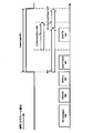
- FIG. 2 is a diagram illustrating a schematic configuration of a radio frame according to the present embodiment.
- the horizontal axis is a time axis.
- Each radio frame includes 10 subframes continuous in the time domain.
- Each subframe i includes two consecutive slots in the time domain. Two consecutive slots in the time domain, the slot of the slot number n s within a radio frame 2i, and the slot number n s within a radio frame is 2i + 1 slot.
- Each radio frame includes 10 subframes continuous in the time domain.
- the subframe is also referred to as TTI (Transmission Time Interval).
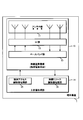
- FIG. 3 is a diagram illustrating a schematic configuration of the uplink slot according to the present embodiment.
- FIG. 3 shows the configuration of an uplink slot in one cell.
- the horizontal axis is a time axis
- the vertical axis is a frequency axis.
- l is an SC-FDMA (Single Carrier-Frequency Division Multiple Access) symbol number / index
- k is a subcarrier number / index.
- a physical signal or physical channel transmitted in each slot is represented by a resource grid.
- the resource grid is defined by a plurality of subcarriers and a plurality of SC-FDMA symbols.
- Each element in the resource grid is referred to as a resource element.
- a resource element is represented by a subcarrier number / index k and an SC-FDMA symbol number / index l.
- Resource grid is defined for each antenna port. In the present embodiment, description will be given for one antenna port. The present embodiment may be applied to each of a plurality of antenna ports.
- N UL symb indicates the number of SC-FDMA symbols included in one uplink slot.
- N UL symb is 7 for normal CP (normal cyclic prefix).
- N UL symb is 6 for extended CP (extended Cyclic Prefix).
- N UL RB is an uplink bandwidth setting for the serving cell, expressed as a multiple of N RB sc .
- N RB sc is a (physical) resource block size in the frequency domain expressed by the number of subcarriers.
- the subcarrier interval ⁇ f is 15 kHz
- N RB sc is 12 subcarriers. That is, in the present embodiment, N RB sc is 180 kHz.
- a resource block is used to represent a mapping of physical channels to resource elements.
- virtual resource blocks and physical resource blocks are defined.
- a physical channel is first mapped to a virtual resource block. Thereafter, the virtual resource block is mapped to the physical resource block.
- One physical resource block is defined by N UL symb consecutive SC-FDMA symbols in the time domain and N RB sc consecutive subcarriers in the frequency domain. Therefore, one physical resource block is composed of (N UL symb ⁇ N RB sc ) resource elements.
- One physical resource block corresponds to one slot in the time domain. Physical resource blocks are numbered (0, 1,..., N UL RB ⁇ 1) in order from the lowest frequency in the frequency domain.
- the downlink slot in this embodiment includes a plurality of OFDM symbols. Since the configuration of the downlink slot in the present embodiment is the same except that the resource grid is defined by a plurality of subcarriers and a plurality of OFDM symbols, description of the configuration of the downlink slot is omitted.
- the following uplink physical channels are used in uplink wireless communication from the terminal device 1 to the base station device 3.
- the uplink physical channel is used by the physical layer to transmit information output from the higher layer.
- -PUCCH Physical Uplink Control Channel
- PUSCH Physical Uplink Shared Channel
- PRACH Physical Random Access Channel
- the PUCCH is used for transmitting uplink control information (UPCI).
- the uplink control information includes downlink channel state information (CSI) and a scheduling request (Scheduling Request) used to request PUSCH (Uplink-Shared Channel: UL-SCH) resources for initial transmission.
- CSI downlink channel state information
- Scheduling Request scheduling request used to request PUSCH (Uplink-Shared Channel: UL-SCH) resources for initial transmission.
- SR SR
- HARQ-ACK Hybrid Automatic Repeat request ACKnowledgement
- MAC PDU Medium Access Control Protocol Data Unit
- DL-SCH Downlink-Shared Channel
- PDSCH Physical Downlink Shared Channel
- HARQ-ACK indicates ACK (acknowledgement) or NACK (negative-acknowledgement).
- HARQ-ACK is also referred to as HARQ feedback, HARQ information, HARQ control information, and ACK / NACK.
- the PUSCH is used to transmit uplink data (Uplink-Shared Channel: UL-SCH).
- the PUSCH may be used to transmit HARQ-ACK and / or channel state information along with uplink data. Also, the PUSCH may be used to transmit only channel state information or only HARQ-ACK and channel state information.
- the PUSCH is used for transmitting the random access message 3.
- PRACH is used for transmitting a random access preamble (random access message 1).
- PRACH indicates the initial connection establishment (initial connection establishment) procedure, handover procedure, connection re-establishment (connection re-establishment) procedure, synchronization (timing adjustment) for uplink transmission, and PUSCH (UL-SCH) resource requirements. Used for.
- Uplink physical signals are used in uplink wireless communication.
- Uplink physical signals are not used to transmit information output from higher layers, but are used by the physical layer.
- UL RS Uplink Reference Signal
- DMRS Demodulation Reference Signal
- SRS Sounding Reference Signal
- DMRS relates to transmission of PUSCH or PUCCH.
- DMRS is time-multiplexed with PUSCH or PUCCH.
- the base station apparatus 3 uses DMRS to perform propagation channel correction for PUSCH or PUCCH.
- transmitting both PUSCH and DMRS is simply referred to as transmitting PUSCH.
- transmitting both PUCCH and DMRS is simply referred to as transmitting PUCCH.
- SRS is not related to PUSCH or PUCCH transmission.
- the base station apparatus 3 may use SRS for measuring the channel state.
- the SRS is transmitted in the last SC-FDMA symbol in the uplink subframe or the SC-FDMA symbol in UpPTS.
- the following downlink physical channels are used in downlink wireless communication from the base station apparatus 3 to the terminal apparatus 1.
- the downlink physical channel is used by the physical layer to transmit information output from the higher layer.
- PBCH Physical Broadcast Channel
- PCFICH Physical Control Format Indicator Channel
- PHICH Physical Hybrid automatic repeat request Indicator Channel
- PDCCH Physical Downlink Control Channel
- EPDCCH Enhanced Physical Downlink Control Channel
- PDSCH Physical Downlink Shared Channel
- PMCH Physical Multicast Channel
- the PBCH is used to broadcast a master information block (Master Information Block: MIB, Broadcast Channel: BCH) commonly used in the terminal device 1.
- MIB Master Information Block
- BCH Broadcast Channel
- SFN system frame number
- MIB is system information. For example, the MIB includes information indicating SFN.
- PCFICH is used for transmitting information indicating a region (OFDM symbol) used for transmission of PDCCH.
- PHICH is used to transmit a HARQ indicator for uplink data (Uplink Shared Channel: UL-SCH) received by the base station apparatus 3.
- the HARQ indicator indicates HARQ-ACK.
- the PDCCH and EPDCCH are used to transmit downlink control information (Downlink Control Information: DCI).
- DCI Downlink Control Information
- the downlink control information is also referred to as a DCI format.
- the downlink control information includes a downlink grant (downlink grant) and an uplink grant (uplink grant).
- the downlink grant is also referred to as downlink assignment (downlink allocation) or downlink assignment (downlink allocation).
- One downlink grant is used for scheduling one PDSCH in one serving cell.
- the downlink grant is used for scheduling the PDSCH in the same subframe as the subframe in which the downlink grant is transmitted.
- One uplink grant is used for scheduling one PUSCH in one serving cell.
- the uplink grant is used for scheduling PUSCH in a subframe that is four or more times after the subframe in which the uplink grant is transmitted.
- the uplink grant transmitted on PDCCH includes DCI format 0.
- the PUSCH transmission method corresponding to DCI format 0 is a single antenna port.
- the terminal device 1 uses a single antenna port transmission scheme for PUSCH transmission corresponding to DCI format 0.
- the PUSCH to which the single antenna port transmission scheme is applied is used for transmission of one codeword (one transport block).
- the uplink grant transmitted on the PDCCH includes DCI format 4.
- the transmission scheme of PUSCH corresponding to DCI format 4 is closed loop spatial multiplexing.
- the terminal device 1 uses a closed-loop spatial multiplexing transmission method for PUSCH transmission corresponding to the DCI format 4.
- the PUSCH to which the closed-loop spatial multiplexing transmission scheme is applied is used for transmission of up to two codewords (up to two transport blocks).
- the CRC parity bits added to the downlink grant or the uplink grant are C-RNTI (Cell-Radio Network Temporary Identifier), Temporary. It is scrambled by C-RNTI or SPS (Semi Persistent Scheduling) C-RNTI Cell-Radio Network Temporary Identifier).
- C-RNTI and SPS C-RNTI are identifiers for identifying a terminal device in a cell. Temporary C-RNTI is used during contention based random access procedures.
- the uplink grant to which the CRC parity bit scrambled by the RNTI is added is also referred to as an uplink grant for the RNTI and an uplink grant corresponding to the RNTI.
- a PDCCH including an uplink grant to which a CRC parity bit scrambled by the RNTI is added is also referred to as a PDCCH corresponding to the RNTI and a PDCCH corresponding to the RNTI.
- the terminal device 1 may transmit the PUSCH including the transport block based on the detection of the PDCCH including the uplink grant to which the CRC parity bit scrambled by the C-RNTI is added.
- the retransmission of the transport block may be indicated by a PDCCH including an uplink grant to which a CRC parity bit scrambled by C-RNTI is added.
- SPS C-RNTI is used to periodically allocate PDSCH or PUSCH resources.
- the terminal device 1 detects the PDCCH including the uplink grant to which the CRC parity bit scrambled by the SPS C-RNTI is added and determines that the uplink grant is valid as the SPS activation command, the terminal device 1 Store the uplink grant as a configured uplink grant (configured uplink grant).
- the MAC layer of the terminal device 1 considers that the set uplink grant occurs periodically.
- the subframe in which the configured uplink grant is considered to be generated is given by the first period and the first offset.
- the terminal device 1 receives information indicating the first period from the base station device 3.
- Retransmission of transport blocks transmitted on the periodically allocated PUSCH is indicated by an uplink grant to which a CRC parity bit scrambled by the SPS C-RNTI is added.
- the set uplink grant is also referred to as an uplink grant set by MAC (Medium Access Control) or a first set uplink grant.
- Random access response includes RAR grant (Random Access Response grant).
- the RAR grant is an uplink grant transmitted on the PDSCH.
- the terminal device 1 may transmit the message 3 using the PUSCH corresponding to the RAR grant.
- the terminal device 1 uses the single antenna port transmission scheme for PUSCH transmission corresponding to the RAR grant and for the PUSCH retransmission for the same transport block.
- Temporary C-RNTI is used to schedule retransmission of random access message 3 and transmission of random access message 4.
- the initial transmission of the random access message 3 is scheduled by a RAR grant (Random Access Response grant).
- the handover command may include an HOC grant (Handover Command grant).
- the HOC grant is an uplink grant transmitted on the PDSCH.
- the terminal device 1 stores the HOC grant as the configured uplink grant (configured uplink grant).
- the MAC layer of the terminal device 1 considers that the set uplink grant occurs periodically.
- the subframe in which the configured uplink grant is considered to be generated is given by the second period and the second offset.
- the handover command includes information indicating the second period and the second offset.
- the handover command includes information indicating the first period.
- the terminal device 1 may use the single antenna port transmission scheme for PUSCH transmission corresponding to the HOC grant and the PUSCH retransmission for the same transport block.
- Retransmission of transport blocks transmitted on the periodically allocated PUSCH may be indicated by an uplink grant to which CRC parity bits scrambled by C-RNTI are added and / or NACK.
- the set uplink grant is also referred to as an uplink grant set by RRC (Radio Resource Control) or a second set uplink grant.
- the SPS C ⁇ is used to retransmit the transport block transmitted on the PUSCH corresponding to the uplink grant (first configured uplink grant) that is considered to be periodically generated based on the first cycle.
- Retransmission of transport blocks transmitted on the PUSCH corresponding to an uplink grant (second configured uplink grant) that is assumed to be generated periodically based on the second cycle, using RNTI C-RNTI is used for this purpose.
- the first period and the second period are set individually.
- the PUSCH corresponding to the uplink grant (first configured uplink grant) that is considered to be periodically generated based on the first period and the first offset is generated based at least on the SPS C-RNTI It may be scrambled by a scramble sequence.
- the PUSCH corresponding to the uplink grant (second configured uplink grant) that is considered to be generated periodically based on the second period and the second offset is generated based on at least the C-RNTI. It may be scrambled by the sequence.
- PDSCH is used to transmit downlink data (Downlink Shared Channel: DL-SCH).
- the PDSCH is used to transmit a random access message 2 (random access response).
- the PDSCH is used for transmitting a handover command.
- PMCH is used to transmit multicast data (Multicast Channel: MCH).
- the downlink physical signal is not used to transmit information output from the upper layer, but is used by the physical layer.
- ⁇ Synchronization signal (SS) ⁇ Downlink Reference Signal (DL RS)
- the synchronization signal is used for the terminal device 1 to synchronize the downlink frequency domain and time domain.
- the synchronization signals include PSS (Primary Synchronization Signal) and SSS (Second Synchronization Signal).
- the downlink reference signal is used for the terminal device 1 to correct the propagation path of the downlink physical channel.
- the downlink reference signal is used for the terminal device 1 to calculate downlink channel state information.
- the following seven types of downlink reference signals are used.
- -CRS Cell-specific Reference Signal
- URS UE-specific Reference Signal
- PDSCH PDSCH
- DMRS Demodulation Reference Signal
- EPDCCH Non-Zero Power Chanel State Information-Reference Signal
- ZP CSI-RS Zero Power Chanel State Information-Reference Signal
- MBSFN RS Multimedia Broadcast and Multicast Service over Single Frequency Network Reference signal
- PRS Positioning Reference Signal
- the downlink physical channel and the downlink physical signal are collectively referred to as a downlink signal.
- the uplink physical channel and the uplink physical signal are collectively referred to as an uplink signal.
- the downlink physical channel and the uplink physical channel are collectively referred to as a physical channel.
- the downlink physical signal and the uplink physical signal are collectively referred to as a physical signal.
- BCH, MCH, UL-SCH and DL-SCH are transport channels.
- a channel used in a medium access control (Medium Access Control: MAC) layer is referred to as a transport channel.
- a transport channel unit used in the MAC layer is also referred to as a transport block (transport block: TB) or a MAC PDU (Protocol Data Unit).
- HARQ HybridbrAutomatic Repeat reQuest
- the transport block is a unit of data that the MAC layer delivers to the physical layer.
- the transport block is mapped to a code word, and an encoding process is performed for each code word.
- the base station device 3 and the terminal device 1 exchange (transmit / receive) signals in a higher layer.
- the base station device 3 and the terminal device 1 transmit / receive RRC signaling (RRC message: Radio Resource Control message, RRC information: also called Radio Resource Control control information) in a radio resource control (RRC: Radio Resource Control) layer. May be.
- RRC signaling RRC message: Radio Resource Control message, RRC information: also called Radio Resource Control control information
- RRC Radio Resource Control
- RRC Radio Resource Control
- the base station device 3 and the terminal device 1 may transmit and receive MAC CE (Control Element) in a medium access control (MAC: Medium Access Control) layer.
- MAC Medium Access Control
- RRC signaling and / or MAC CE is also referred to as higher layer signaling.
- the PUSCH and PDSCH are used to transmit RRC signaling and MAC CE.
- the RRC signaling transmitted by the PDSCH from the base station apparatus 3 may be common signaling for a plurality of terminal apparatuses 1 in the cell.
- the RRC signaling transmitted from the base station device 3 on the PDSCH may be dedicated signaling for a certain terminal device 1 (also referred to as dedicated signaling or UE specific signaling).
- the cell specific parameter may be transmitted using common signaling for a plurality of terminal devices 1 in a cell or dedicated signaling for a certain terminal device 1.
- the UE specific parameter may be transmitted to a certain terminal device 1 using dedicated signaling.
- FIG. 4 is a diagram illustrating an example of a handover procedure in the present embodiment.
- the target base station device 3B transmits a handover command to the source base station device 3A.
- the handover command is a parameter RRCConnectionReconfiguration including the parameter mobilityControlInfo.
- the parameter mobilityControlInfo includes information on transmission timing in the target cell, HOC grant, information for indicating C-RNTI in the target cell, information for indicating SPS C-RNTI in the target cell, information indicating the first period, second Information indicating the period and the second offset, and information on the target cell may be included.
- the information regarding the target cell may include information for indicating the PCI (Physical layer layer Cell Identity) of the target cell and information for indicating the frequency of the target cell.
- PCI Physical layer layer Cell Identity
- Step 401 The source base station apparatus 3A transmits the handover command received from the source base station apparatus 3A to the terminal apparatus 1 using PDSCH.
- the terminal device 1 acquires downlink synchronization of the target cell based on information on the target cell.
- the terminal device 1 may use part or all of the synchronization signal of the target cell, the CRS of the target cell, and the PBCH of the target cell in order to acquire downlink synchronization.
- the terminal apparatus 1 transmits uplink data on the first PUSCH in the target cell.
- the first PUSCH in the target cell corresponds to the second configured uplink grant. May be.
- the uplink data may include a complete message (RRCConnectionReconfigurationCompletemessage).
- the transmission timing of the first PUSCH transmission is set based on information related to the transmission timing in the target cell.
- Step 404 The terminal device 1 attempts to receive / decode a response to the PUSCH (uplink data) corresponding to the HOC grant for a predetermined period in the target cell.
- the response may include some or all of the following.
- Response type A PHICH for uplink data transmitted on PUSCH corresponding to the second configured uplink grant (ACK only, except NACK)
- Response type B PDCCH / EPDCCH including C-RNTI indicated by handover command (Step 405)
- the terminal apparatus 1 transmits uplink data using PUSCH based on the second configured uplink grant.
- the uplink data may include a complete message (RRCConnectionReconfigurationCompletemessage).
- Step 406 The terminal apparatus 1 detects a response to the PUSCH transmission in Step 405.
- the terminal device 1 may end the process of the handover procedure based on the detection of the response.
- the terminal device 1 may consider that the handover is successful based on detecting the response.
- Step 407 When the terminal device 1 detects NACK in Step 406, the terminal device 1 retransmits the uplink data on the PUSCH based on the HOC grant. Retransmission based on NACK is referred to as non-adaptive retransmission.
- Step 407 When the terminal apparatus 1 detects a PDCCH / EPDCCH including an uplink grant instructing retransmission in Step 406, the terminal apparatus 1 retransmits uplink data on the PUSCH based on the uplink grant.
- the retransmission based on the uplink grant is referred to as an adaptive retransmission.
- the CRC parity bit added to the uplink grant is scrambled by C-RNTI.
- FIG. 5 is a diagram for explaining the fields included in the uplink grant according to the present embodiment.
- the 'Resource block' assignment 'and' hopping 'resource' allocation 'field is used to indicate a physical resource block to which a PUSCH is assigned.
- the 'Resource block' assignment 'and' hopping 'resource' allocation 'field may be included in both DCI format 0 and HOC grant.
- the 'Modulation and coding scheme and redundancy version' field is used to indicate the transport block size, modulation order Q ' m , and redundancy version rv idx .
- the 'Modulation and coding scheme and redundancy version' field may be included in both DCI format 0 and HOC grant.
- the 'New data indicator' field is used for instructing initial transmission or retransmission of PUSCH (transport block).
- the 'New data indicator' field may be included in DCI format 0.
- the 'New data indicator' field is not included in the HOC grant.
- the terminal device 1 has one MAC entity.
- the MAC entity controls (manages) one or more HARQ entities.
- In the uplink in which carrier aggregation is set there is one independent HARQ entity (entity) for each serving cell (uplink component carrier).
- the HARQ entity manages multiple HARQ processes in parallel.
- the HARQ process is associated with the HARQ buffer. That is, the HARQ entity is associated with multiple HARQ buffers.
- the HARQ process stores the MAC layer data in the HARQ buffer.
- the HARQ process instructs the physical layer to transmit the MAC layer data.
- At least one transport block is generated for each subframe for each serving cell.
- Each transport block and the HARQ retransmissions for that transport block are mapped to one serving cell.
- the MAC entity and the HARQ entity may specify the ID (identity) of the HARQ process corresponding to the uplink grant based on the subframe that has received the PDCCH including the uplink grant.
- the MAC entity and the HARQ entity identify the ID (identity) of the corresponding HARQ process based on the subframe in which the first configured uplink grant or the second configured uplink grant is considered to occur. Also good.
- the HARQ entity passes the uplink grant to the identified HARQ process.
- the HARQ entity instructs the HARQ process to trigger an initial transmission if the NDI provided for a HARQ process is toggled relative to the value of the NDI for a previous transmission of the HARQ process. .
- the HARQ entity instructs the HARQ process to trigger an adaptive retransmission if the NDI provided for a HARQ process is not toggled compared to the NDI value for a previous transmission of the HARQ process.
- the HARQ process may determine whether the NDI is toggled.
- the NDI for transmission before the certain HARQ process corresponds to an uplink grant to which CRC parity bits scrambled by C-RNTI are added.
- the terminal device 1 uses the uplink grant to which the CRC parity bit scrambled by the Temporary C-RNTI is added. Ignore the included NDI.
- the MAC entity and the HARQ entity consider the NDI for the HARQ process to be toggled. That is, if an uplink grant that is considered to occur periodically is passed to the HARQ process, the MAC entity and the HARQ entity consider the NDI for the HARQ process to be toggled.
- Previous uplink grant (indicated by the uplink grant for a HARQ process, the uplink grant corresponds to C-RNTI, and passed by the HARQ entity for the HARQ process) If previous uplink grant) is the first configured uplink grant, the MAC entity and the HARQ entity consider NDI to be toggled for that HARQ process regardless of the value of NDI.
- Previous uplink grant (indicated by the uplink grant for a HARQ process, the uplink grant corresponds to C-RNTI, and passed by the HARQ entity for the HARQ process) If previous uplink grant) is the second configured uplink grant, the MAC entity and the HARQ entity determine whether NDI is toggled for the certain HARQ process based on the value of NDI. This enables adaptive retransmission of transport blocks transmitted based on the second configured uplink grant.
- the terminal apparatus 1 may have received the previous HARQ entity for the certain HARQ process. It may be determined whether the uplink grant (previous uplink grant) is an uplink grant (uplink grant corresponding to the first period) set by the MAC. When the previous uplink grant (previous uplink grant) passed by the HARQ entity for the certain HARQ process is an uplink grant set by the MAC (uplink grant corresponding to the first period), the terminal apparatus 1 may be considered that the MAC entity and the HARQ entity are NDI toggled for the certain HARQ process regardless of the value of the NDI.
- the terminal device 1 may determine whether NDI is toggled for the certain HARQ process based on the received value of NDI. That is, when the previous uplink grant (previous uplink grant) passed by the HARQ entity for the certain HARQ process is an uplink grant set by RRC (uplink grant corresponding to the second period), The terminal device 1 may determine whether NDI is toggled for the certain HARQ process based on the received value of NDI.
- PDCCH including downlink control information (uplink grant, downlink grant) including toggled NDI” is also referred to as “PDCCH instructing initial transmission”.
- PDCH including downlink control information (uplink grant, downlink grant) including non-toggled NDI” is also referred to as “PDCCH instructing adaptive retransmission”.
- the base station apparatus 3 may assume the operation of the terminal apparatus when performing scheduling of PUSCH.
- step 403 of FIG. 4 when the information regarding the transmission timing in the target cell is not set, the terminal device 1 starts a random access procedure in the target cell.
- the first PUSCH transmission in the target cell corresponds to the RAR grant.
- step 403 of FIG. 4 when information related to transmission timing in the target cell is set and there is no second configured uplink grant, the first PUSCH in the target cell is the uplink included in the PDCCH. Link grants may be supported. The case where the second configured uplink grant does not exist is the same as the case where the HOC grant is not included in the handover command.
- Step 403 of FIG. 4 when information regarding transmission timing in the target cell is set and there is no second set uplink grant, the terminal device 1 monitors the PDCCH in the target cell.
- PDCCH includes PDCCH corresponding to C-RNTI and PDCCH corresponding to SPS C-RNTI.
- the terminal device 1 may monitor the PDCCH until the PDCCH corresponding to the first PUSCH is detected.
- DRX Continuous Reception
- the DRX functionality is set by the upper layer (RRC) and processed by MAC.
- the DRX function controls the PDCCH monitoring activity of the terminal device 1 for the C-RNTI and SPS C-RNTI of the terminal device 1.
- the handover command may include information indicating the DRX setting in the target cell.
- the DRX function controls the monitoring activity of the terminal device 1 for the PDCCH used for transmission of the DCI format to which the CRC parity bit scrambled by the C-RNTI of the terminal device 1 is added.
- the DRX function may not be applied to the monitoring activity of the terminal apparatus 1 for the PDCCH used for transmission of the DCI format to which the CRC parity bit scrambled by a predetermined RNTI is added.
- the terminal device 1 may monitor the PDCCH discontinuously using the DRX operation described below. In other cases, the terminal device 1 may continuously monitor the PDCCH.
- the upper layer controls the DRX operation by setting the following timers and the value of drxStartOffset.
- OnDurationTimer ⁇ Drx-InactivityTimer Drx-RetransmissionTimer (one for each downlink HARQ process excluding the downlink HARQ process for the broadcast process)
- Drx-ULRetransmissionTimer one for each uplink HARQ process
- LongDRX-Cycle HARQ RTT Red Trip Time
- timer one for each downlink HARQ process
- UL HARQ RTT Timer one for each uplink HARQ process
- DrxShortCycleTimer ⁇ ShortDRX-Cycle
- the base station device 3 transmits to the terminal device 1 an RRC message including parameters / information indicating the values of onDurationTimer, drx-InactivityTimer, drx-RetransmissionTimer, drx-ULRetransmissionTimer, longDRX-Cycle, drxShortC
- the terminal device 1 may set the values of onDurationTimer, drx-InactivityTimer, drx-RetransmissionTimer, drx-ULRetransmissionTimer, longDRX-Cycle, drxShortCycleTimer, shortDRX-Cycle, and drxStartOffset based on the received RRC message.
- DRX cycle LongDRX-Cycle and shortDRX-Cycle are also collectively referred to as DRX cycle.
- OnDurationTimer indicates the number of consecutive PDCCH subframes from the beginning of the DRX cycle.
- Drx-InactivityTimer indicates the number of consecutive PDCCH subframes after the subframe to which the PDCCH instructing initial transmission of uplink data or downlink data to the terminal device 1 is mapped.
- Drx-RetransmissionTimer indicates the maximum number of consecutive PDCCH subframes for downlink retransmission expected by the terminal device 1. The same value of drx-RetransmissionTimer is applied to all serving cells.
- Drx-ULRetransmissionTimer indicates the maximum number of consecutive PDCCH subframes until an uplink grant for uplink retransmission (uplink HARQ retransmission grant) is received.
- the same value of drx-ULRetransmissionTimer is applied to all serving cells to which asynchronous HARQ is applied for the uplink.
- the DRX cycle indicates a repetition period of on duration (On Duration).
- On Duration The on-duration period is followed by a period during which inactivity of PDCCH monitoring of the terminal device 1 for the C-RNTI and SPS C-RNTI of the terminal device 1 is possible.
- FIG. 6 is a diagram illustrating an example of a DRX cycle in the present embodiment.
- the horizontal axis is a time axis.
- the terminal device 1 monitors the PDCCH.
- a period P602 after the on-duration period P600 is a period during which inactivity is possible. That is, in FIG. 6, the terminal device 1 does not have to monitor the PDCCH in the period P602.
- DrxShortCycleTimer indicates the number of consecutive subframes that the terminal device 1 follows the short DRX cycle.
- DrxStartOffset indicates the subframe in which the DRX cycle starts.
- the HARQ RTT timer corresponding to the downlink HARQ process is managed for each downlink HARQ process in relation to the start of the drx-RetransmissionTimer.
- the HARQ RTT timer corresponding to the downlink HARQ process indicates a minimum interval from transmission of downlink data to retransmission of the downlink data. That is, the HARQ RTT timer corresponding to the downlink HARQ process indicates the minimum amount of subframes before downlink HARQ retransmission is expected by the terminal device 1.
- one downlink HARQ process controls HARQ of one downlink data (transport block). Note that one downlink HARQ process may control two downlink data.
- the UL HARQ RTT timer corresponding to the uplink HARQ process is managed for each uplink HARQ process in relation to the start of the drx-ULRetransmissionTimer.
- the UL HARQ RTT timer corresponding to the uplink HARQ process indicates a minimum interval from transmission of uplink data to transmission of an uplink grant (uplink HARQ retransmission grant) for retransmission of the uplink data. That is, the UL HARQ RTT timer corresponding to the uplink HARQ process is the minimum amount of subframes before the terminal device 1 expects an uplink grant for uplink retransmission (uplink HARQ retransmission grant) (minimum amount).
- the same active time may be applied to all serving cells.
- Different active times may be applied to each of the serving cell belonging to the first cell group and the serving cell belonging to the second cell group.
- the same active time may be applied to all serving cells belonging to the first cell group.
- the same active time may be applied to all serving cells belonging to the second cell group. That is, DRX may be individually controlled in each of the first cell group and the second cell group. That is, for each of the first cell group and the second cell group, the values of onDurationTimer, drx-InactivityTimer, drx-RetransmissionTimer, drx-ULRetransmissionTimer, longDRX-Cycle, drxShortCycleTimer, shortDRX-Cycle, and drxStartOffset May be set individually.
- the active time may include a period that satisfies at least one of the following conditions (a) to (e).
- the preamble that is not selected by the terminal device 1 includes a preamble indicated by information included in the handover command.
- “PDCCH instructing initial transmission” in the above condition may be “PDCCH instructing initial transmission in downlink or uplink”.
- the RNTI of the terminal device 1 may be C-RNTI.
- the RNTI of the terminal device 1 may be C-RNTI or SPS C-RNTI.
- “PDCCH instructing initial transmission” in the above condition may be “PDCCH instructing uplink initial transmission”.
- “PDCCH instructing initial transmission” in the above condition may be “PDCCH instructing initial transmission in downlink or uplink”.
- “no PDCCH has been received” may mean that the PDCCH has never been received in the target cell after resetting the MAC based on the reception of the handover command.
- condition used to determine whether or not a certain period is included in the active time is not limited to the condition (a) to the condition (e), and is different from the condition (a) to the condition (e).
- Conditions may be used, or a part of the conditions (e) to (e) may be used.
- timer Once the timer starts, it is running until the timer is stopped or the timer expires. Otherwise, the timer is not running. If the timer is not running, the timer may be started. If the timer is running, the timer may be restarted. The timer is always started or restarted from the initial value of the timer.
- the preamble is a random access procedure message 1 and is transmitted by PRACH.
- the preamble not selected by the terminal device 1 is related to the contention based random access procedure.
- the random access response is message 2 of the random access procedure and is transmitted by PDSCH.
- the base station device 3 transmits a random access response to the received preamble.
- the terminal device 1 that is executing the contention based random access procedure transmits the message 3 after receiving the random access response.
- the terminal device 1 monitors the PDCCH related to the message 4 after the message 3 is transmitted.
- Mac-ContentionResolutionTimer indicates the number of consecutive subframes in which the terminal device 1 monitors the PDCCH after the message 3 is transmitted.
- FIGS. 7 and 8 are flowcharts showing an example of the DRX operation in the present embodiment.
- the terminal device 1 performs a DRX operation based on the flowcharts of FIGS. 7 and 8 for each of the subframes.
- the terminal device 1 If the HARQ RTT timer corresponding to the downlink HARQ process expires in this subframe and the HARQ process data corresponding to the HARQ RTT timer has not been successfully decoded (S700: YES), the terminal device 1 starts drx-RetransmissionTimer for the downlink HARQ process corresponding to the HARQ RTT timer (S702), and proceeds to S703A. In other cases (S700: NO), the terminal device 1 proceeds to S703A.
- the terminal apparatus 1 sets drx-ULRetransmissionTimer for the uplink HARQ process corresponding to the UL HARQ RTT timer. Start (S703B), and then proceed to S704. In other cases (S703A: NO), the terminal device 1 proceeds to S704.
- the terminal device 1 stops onDurationTimer and drx-InactivityTimer (S706), and proceeds to S708. In other cases (S704: NO), the terminal device 1 proceeds to S708.
- the terminal device 1 proceeds to S710. In other cases (S708: NO), the terminal device 1 proceeds to S716.
- the terminal device 1 uses the long DRX cycle (S712), and proceeds to S716. If the short DRX cycle (shortDRX-Cycle) is set (S710: YES), the terminal device 1 starts or restarts the drxShortCycleTimer, uses the short DRX cycle (S714), and proceeds to S716.
- the terminal device 1 uses the long DRX cycle (S718), and proceeds to S800 of FIG. In other cases (S716: NO), the terminal device 1 proceeds to S800 in FIG.
- the terminal device 1 and the base station device 3 may specify the PDCCH subframe based on the UL-DL configuration for the TDD serving cell.
- Half duplex FDD operations include type A half duplex FDD operations and type B half duplex FDD operations.
- the terminal device 1 may transmit information indicating whether or not the type A half-duplex FDD is supported in the FDD band to the base station device 3.
- the terminal device 1 may transmit information indicating whether to support type B half-duplex FDD in the FDD band to the base station device 3.
- the terminal device 1 cannot simultaneously perform uplink transmission and downlink reception.
- the subframe immediately before the subframe in which the terminal device 1 performs uplink transmission and the subframe immediately after the subframe in which the mobile station device 1 performs uplink transmission Each is a half-duplex guard subframe.
- the terminal device 1 cannot simultaneously perform uplink transmission and downlink reception.
- the terminal device 1 cannot receive the downlink in the subframe immediately before the subframe in which uplink transmission is performed.
- the terminal device 1 cannot receive downlink in a subframe immediately after a subframe in which uplink transmission is performed.
- the measurement gap is a time interval for the terminal device 1 to measure different frequency cells and / or different RAT (Radio Access Technology).
- the base station device 3 transmits information indicating the measurement gap period to the terminal device 1.
- the terminal device 1 sets the measurement gap period based on the information.
- the terminal device 1 ends the DRX operation for this subframe. That is, if at least one of the conditions (e) to (i) is not satisfied, the terminal device 1 may not monitor the PDCCH in this subframe.
- the conditions used in S804 are not limited to the conditions (e) to (i). In S804, conditions different from the conditions (e) to (i) may be used, or the conditions (e ) To a part of condition (i) may be used.
- the terminal device 1 If the downlink assignment received via the PDCCH indicates downlink transmission, or if the downlink assignment is set for this subframe (S808: YES), the terminal device 1 The HARQRTT timer for the corresponding downlink HARQ process is started, drx-RetransmissionTimer for the corresponding downlink HARQ process is stopped (S810), and the process proceeds to step S811A. In other cases (S808: NO), the terminal device 1 proceeds to S811A.
- the length of the HARQ RTT timer may be 8.
- the state in which the downlink assignment is set means a state in which semi-persistent scheduling is activated by the downlink assignment with the SPS C-RNTI.
- the terminal device 1 If the uplink grant received via the PDCCH instructs uplink transmission for the asynchronous HARQ process (S811A: YES), the terminal device 1 (i) in the subframe including the PUSCH transmission corresponding to the uplink grant Start a UL HARQ RTT timer for the uplink HARQ process corresponding to the uplink grant; (ii) stop drx-ULRetransmissionTimer for the uplink HARQ process corresponding to the uplink grant (S811B); iii) Proceed to step S812. In other cases (S811A: NO), the terminal device 1 proceeds to S812.
- the length of the UL HARQ RTT timer may be four.
- the terminal device 1 If the downlink assignment or uplink grant received via the PDCCH instructs the initial transmission of the downlink or uplink (S812: YES), the terminal device 1 starts or restarts drx-InactivityTimer ( S814), and the DRX operation for this subframe is terminated. In other cases (S812: NO), the terminal device 1 ends the DRX operation for this subframe.
- FIG. 9 is a diagram showing a first example of active time in the present embodiment.
- the terminal device 1 receives the handover command 900 in the source cell.
- the handover command 900 does not include information regarding transmission timing in the target cell and includes information indicating a preamble.
- the RRC of the terminal device 1 provides a complete message (RRCConnectionReconfigurationCompletemessage) for transmission to the MAC.
- the MAC triggers a BSR (bufferstatus report) based on the occurrence of data for transmission (complete message).
- the MAC triggers an SR (scheduling request) based on the trigger of the BSR. If the SR is triggered, it is considered pending until the SR is canceled.
- At least one SR is pending, there is no UL-SCH resource available for transmission in this subframe, and the MAC entity has a valid PUCCH resource for SR in any subframe If not, the MAC entity initiates a random access procedure in the primary cell.
- the UL-SCH resource may include a PUSCH resource allocated by the uplink grant.
- the handover command 900 may include PUCCH configuration for SR, but the PUCCH configuration for SR is configured after the random access procedure is completed. That is, in FIG. 9, the MAC entity has a pending SR triggered by a complete message, and the MAC entity does not have a valid PUCCH resource for the SR in any subframe. Initiate a random access procedure in the primary cell.
- the terminal device 1 transmits a PRACH including a preamble in the target cell.
- the preamble is selected based on information indicating the preamble included in the handover command. That is, the random access procedure in FIG. 9 is a non-contention based random access procedure.
- the terminal device 1 receives the PDSCH 902 including a random access response corresponding to the transmitted preamble. The terminal device 1 considers that the random access procedure has been successfully completed based on the reception of the random access response.
- the terminal device 1 may transmit the complete message using the PUSCH 903 corresponding to the RAR grant included in the random access response.
- the active time 905 may include a period 908 in which the PDCCH 904 indicating the initial transmission (uplink or downlink) corresponding to the C-RNTI after the successful reception of the random access response 902 is not received.
- FIG. 10 is a diagram showing a second example of the active time in the present embodiment.
- the terminal device 1 receives the handover command 1000 in the source cell.
- the handover command 1000 includes information regarding transmission timing in the target cell and does not include an HOC grant.
- the RRC of the terminal device 1 instructs the MAC to transmit a complete message (RRCConnectionReconfigurationCompletemessage).
- the MAC triggers a BSR (buffer status report) based on the occurrence of data that can be transmitted (complete message).
- the MAC triggers an SR (scheduling request) based on the trigger of the BSR. If the SR is triggered, it is considered pending until the SR is canceled.
- the UL-SCH resource may include a PUSCH resource allocated by the uplink grant.
- the handover command 1000 may include PUCCH setting for SR, but the PUCCH setting for SR is set after the random access procedure is completed. That is, in FIG. 10, the MAC entity is pending SR triggered due to a complete message, and the MAC entity does not have a valid PUCCH resource for SR in any subframe.
- the MAC entity When information on transmission timing in the target cell is set, the MAC entity does not have to start the random access procedure in the primary cell until the first PUSCH 1002 is transmitted in the target cell. For example, at least one SR is pending, there is no UL-SCH resource available for transmission in this subframe, and the MAC entity has a valid PUCCH resource for SR in any subframe. Even if not, if the information regarding the transmission timing in the target cell is set, the MAC entity does not start the random access procedure in the primary cell until the first PUSCH 1002 is transmitted.
- the MAC entity may not start the random access procedure in the primary cell until a response to the first PUSCH 1002 in the target cell is received. For example, at least one SR is pending, there is no UL-SCH resource available for transmission in this subframe, and the MAC entity has a valid PUCCH resource for SR in any subframe. Even if not, if information regarding transmission timing in the target cell is set, the MAC entity does not initiate a random access procedure in the primary cell until a response to the first PUSCH transmission 1002 is received.
- the MAC entity When the information regarding the transmission timing in the target cell is set, the MAC entity does not need to trigger the SR until the first PUSCH 1002 is transmitted. Or when the information regarding the transmission timing in a target cell is set, the MAC entity does not need to trigger SR until the response with respect to the first PUSCH transmission 1002 is received.
- Terminal apparatus 1 monitors PDCCH during active time 1005 in the target cell.
- the PDCCH includes a PDCCH for C-RNTI and a PDCCH for SPS C-RNTI.
- the active time 1005 may include a period 1009 in which the PDCCH 1001 instructing initial transmission has never been received in the target cell.
- “PDCCH instructing initial transmission” may be “PDCCH instructing initial transmission in uplink”.
- “PDCCH instructing initial transmission” may be “PDCCH instructing initial transmission in downlink or uplink”.
- the period 1009 may start when a handover command is received.
- the period 1009 may start when the setting based on the handover command is performed.
- the period 1009 may start when downlink synchronization of the target cell is acquired.
- Period 1009 may start when the preparation for PDCCH monitoring in the target cell is completed.
- the terminal device 1 may transmit a complete message using the PUSCH 1002 corresponding to the PDCCH 1001.
- the transmission timing of the PUSCH transmission 1002 is set based on “information regarding transmission timing in the target cell”.
- the MAC entity may start a random access procedure in the primary cell.
- the MAC entity may initiate a random access procedure in the primary cell.
- the base station apparatus 3 may transmit a PDCCH instructing initial transmission in the target cell after a predetermined time has passed from the handover command to the source cell.
- the active time 1005 may not include the period 1009 during which the PDCCH 1001 instructing the initial transmission has not been received in the target cell.
- the active time 1005 may not include the period 1009 in which the PDCCH 1001 instructing the initial transmission has never been received in the target cell.
- the terminal device 1 may monitor the PDCCH 1001 in the period 1009.
- the active time 1005 may include a period during which a predetermined timer is running.
- the predetermined timer may be started based on reception of a handover command.
- the predetermined timer may be started based on the setting based on the handover command.
- the predetermined timer may be started based on acquisition of downlink synchronization of the target cell.
- the predetermined timer may be started based on completion of preparation for PDCCH monitoring in the target cell.
- the predetermined timer may be stopped based on reception of the PDCCH 1001 instructing initial transmission.
- the handover command may include information indicating the length of the timer.
- the base station apparatus 3 may assume the operation of the terminal apparatus when performing scheduling of PUSCH. For example, the base station apparatus 3 may determine the timing for transmitting the PDCCH 1001 by assuming the operation of the terminal apparatus.
- the terminal device 1 can efficiently perform uplink transmission.
- FIG. 11 is a schematic block diagram showing the configuration of the terminal device 1 of the present embodiment.
- the terminal device 1 includes a wireless transmission / reception unit 10 and an upper layer processing unit 14.
- the wireless transmission / reception unit 10 includes an antenna unit 11, an RF (Radio Frequency) unit 12, and a baseband unit 13.
- the upper layer processing unit 14 includes a medium access control layer processing unit 15 and a radio resource control layer processing unit 16.
- the wireless transmission / reception unit 10 is also referred to as a transmission unit, a reception unit, or a physical layer processing unit.
- the upper layer processing unit 14 outputs the uplink data (transport block) generated by the user operation or the like to the radio transmission / reception unit 10.
- the upper layer processing unit 14 includes a medium access control (MAC: Medium Access Control) layer, a packet data integration protocol (Packet Data Convergence Protocol: PDCP) layer, a radio link control (Radio Link Control: RLC) layer, a radio resource control (Radio). Resource (Control: RRC) layer processing.
- MAC Medium Access Control
- PDCP Packet Data Convergence Protocol
- RLC Radio Link Control
- Radio Radio Resource
- Control Control
- the medium access control layer processing unit 15 included in the upper layer processing unit 14 performs processing of the medium access control layer.
- the medium access control layer processing unit 15 controls transmission of the scheduling request based on various setting information / parameters managed by the radio resource control layer processing unit 16.
- the radio resource control layer processing unit 16 included in the upper layer processing unit 14 performs processing of the radio resource control layer.
- the radio resource control layer processing unit 16 manages various setting information / parameters of the own device.
- the radio resource control layer processing unit 16 sets various setting information / parameters based on the upper layer signal received from the base station apparatus 3. That is, the radio resource control layer processing unit 16 sets various setting information / parameters based on information indicating various setting information / parameters received from the base station apparatus 3.
- the wireless transmission / reception unit 10 performs physical layer processing such as modulation, demodulation, encoding, and decoding.
- the radio transmission / reception unit 10 separates, demodulates, and decodes the signal received from the base station apparatus 3 and outputs the decoded information to the upper layer processing unit 14.
- the radio transmission / reception unit 10 generates a transmission signal by modulating and encoding data, and transmits the transmission signal to the base station apparatus 3.
- the RF unit 12 converts the signal received via the antenna unit 11 into a baseband signal by orthogonal demodulation (down-conversion: down covert), and removes unnecessary frequency components.
- the RF unit 12 outputs the processed analog signal to the baseband unit.
- the baseband unit 13 converts the analog signal input from the RF unit 12 into a digital signal.
- the baseband unit 13 removes a portion corresponding to CP (Cyclic Prefix) from the converted digital signal, performs fast Fourier transform (FFT) on the signal from which CP has been removed, and generates a frequency domain signal. Extract.
- CP Cyclic Prefix
- FFT fast Fourier transform
- the baseband unit 13 performs inverse fast Fourier transform (Inverse Fastier Transform: IFFT) to generate an SC-FDMA symbol, adds a CP to the generated SC-FDMA symbol, and converts a baseband digital signal into Generating and converting a baseband digital signal to an analog signal.
- IFFT inverse fast Fourier transform
- the baseband unit 13 outputs the converted analog signal to the RF unit 12.
- the RF unit 12 removes an extra frequency component from the analog signal input from the baseband unit 13 using a low-pass filter, up-converts the analog signal to a carrier frequency, and transmits the signal via the antenna unit 11. To do.
- the RF unit 12 amplifies power. Further, the RF unit 12 may have a function of controlling transmission power.
- the RF unit 12 is also referred to as a transmission power control unit.
- FIG. 12 is a schematic block diagram showing the configuration of the target base station device 3B of the present embodiment.
- the target base station device 3B includes a wireless transmission / reception unit 30 and an upper layer processing unit 34.
- the wireless transmission / reception unit 30 includes an antenna unit 31, an RF unit 32, and a baseband unit 33.
- the upper layer processing unit 34 includes a medium access control layer processing unit 35 and a radio resource control layer processing unit 36.
- the wireless transmission / reception unit 30 is also referred to as a transmission unit, a reception unit, or a physical layer processing unit.
- the configuration of the source base station device 3A may be the same as the configuration of the target base station device 3B.
- the upper layer processing unit 34 includes a medium access control (MAC: Medium Access Control) layer, a packet data integration protocol (Packet Data Convergence Protocol: PDCP) layer, a radio link control (Radio Link Control: RLC) layer, a radio resource control (Radio). Resource (Control: RRC) layer processing.
- MAC Medium Access Control
- PDCP Packet Data Convergence Protocol
- RLC Radio Link Control
- Radio Radio Resource Control
- the medium access control layer processing unit 35 included in the upper layer processing unit 34 performs processing of the medium access control layer.
- the medium access control layer processing unit 35 performs processing related to the scheduling request based on various setting information / parameters managed by the radio resource control layer processing unit 36.
- the upper layer processing unit 34 may transmit information to other base station apparatuses and the MME / GW 3C.
- the upper layer processing unit 34 may receive information from other base station apparatuses and the MME / GW 3C.
- the radio resource control layer processing unit 36 included in the upper layer processing unit 34 performs processing of the radio resource control layer.
- the radio resource control layer processing unit 36 generates downlink data (transport block), system information, RRC message, MAC CE (Control Element), etc. arranged in the physical downlink shared channel, or acquires it from the upper node. , Output to the wireless transceiver 30.
- the radio resource control layer processing unit 36 manages various setting information / parameters of each terminal device 1.
- the radio resource control layer processing unit 36 may set various setting information / parameters for each terminal device 1 via an upper layer signal. That is, the radio resource control layer processing unit 36 transmits / notifies information indicating various setting information / parameters.
- Each of the units denoted by reference numerals 10 to 16 included in the terminal device 1 may be configured as a circuit.
- Each of the parts denoted by reference numerals 30 to 36 included in the base station device 3 may be configured as a circuit.
- a first aspect of the present embodiment is a terminal apparatus, comprising: a receiving unit that receives an uplink grant; and a medium access control layer processing unit that executes processing of a HARQ entity, wherein the medium access
- the layer processing unit indicates a first uplink grant to the HARQ process, the first uplink grant corresponds to C-RNTI, and the HARQ entity passes for the HARQ process. If the previous second uplink grant is an uplink grant set by the MAC, the NDI is toggled for the HARQ process regardless of the value of the NDI included in the first uplink grant.
- the medium access layer processing unit is instructed by the first uplink grant to the HARQ process.
- the first uplink grant corresponds to C-RNTI
- the second uplink grant before passed by the HARQ entity for the HARQ process is set by the RRC. If it is, it is determined whether NDI is toggled for the HARQ process based on the value of NDI included in the first uplink grant.
- a second aspect of the present embodiment is a base station device, and a transmission unit that transmits an uplink grant to a terminal device; A receiving unit that receives PUSCH from the terminal device; and a medium access control layer processing unit that performs PUSCH scheduling.
- the medium access layer processing unit performs scheduling of the PUSCH, the following (1) And (2) are assumed.
- the terminal apparatus is instructed by a first uplink grant to the HARQ process, the first uplink grant corresponds to C-RNTI, and the HARQ process is performed for the HARQ process. If the previous uplink grant passed by the entity is an uplink grant set by the MAC, the NDI is toggled for the HARQ process regardless of the value of the NDI included in the first uplink grant. It is considered.
- the terminal apparatus is instructed by the first uplink grant to the HARQ process, the first uplink grant corresponds to C-RNTI, and for the HARQ process If the previous second uplink grant passed by the HARQ entity is an uplink grant set by RRC, based on the value of the NDI included in the first uplink grant, the HARQ process Determine if NDI is toggled.
- a third aspect of the present embodiment is a terminal apparatus, a medium access control layer processing unit that executes DRX for controlling PDCCH monitoring activity, and a receiving unit that receives a handover command in a source cell And (ii) if the handover command includes information on transmission timing in the target cell and (ii) does not include an uplink grant, the active time for the DRX in the target cell is the target It includes at least a first period during which no first PDCCH instructing initial transmission is received in the cell.
- a fourth aspect of the present embodiment is a base station device, which performs scheduling of PUSCH, a transmitting unit that transmits an uplink grant to the terminal device, a receiving unit that receives PUSCH from the terminal device, and A medium access control layer processing unit, and the medium access layer processing unit assumes the following (1) when scheduling the PUSCH.
- the handover command includes (i) information on transmission timing in the target cell and (ii) does not include an uplink grant
- the active time for the DRX in the target cell is It includes at least a first period in which the first PDCCH instructing initial transmission is not received.
- the medium access control layer processing unit does not start a random access procedure in the first period.
- the initial transmission is uplink initial transmission.
- the initial transmission includes uplink initial transmission and downlink initial transmission.
- the PDCCH is a PDCCH corresponding to C-RNTI.
- the PDCCH includes a PDCCH corresponding to C-RNTI and a PDCCH corresponding to SPS C-RNTI.
- the terminal device and the base station device can communicate with each other efficiently.
- the base station device 3 can be realized as an aggregate (device group) composed of a plurality of devices.
- Each of the devices constituting the device group may include a part or all of each function or each functional block of the base station device 3 according to the above-described embodiment.
- the device group only needs to have one function or each function block of the base station device 3.
- the terminal device 1 according to the above-described embodiment can also communicate with the base station device as an aggregate.
- the base station apparatus 3 in the above-described embodiment may be EUTRAN (Evolved Universal Terrestrial Radio Access Network). Further, the base station apparatus 3 in the above-described embodiment may have a part or all of the functions of the upper node for the eNodeB.
- EUTRAN Evolved Universal Terrestrial Radio Access Network
- a program that operates in a device is a program that controls a central processing unit (CPU) or the like to function a computer so as to realize the functions of the above-described embodiments according to one aspect of the present invention.
- CPU central processing unit
- the program or the information handled by the program is temporarily read into volatile memory such as Random Access Memory (RAM) during processing, or stored in nonvolatile memory such as flash memory or Hard Disk Drive (HDD).
- RAM Random Access Memory
- HDD Hard Disk Drive
- the CPU reads and corrects / writes.
- the program for realizing the control function may be recorded on a computer-readable recording medium, and the program recorded on the recording medium may be read by the computer system and executed.
- the “computer system” here is a computer system built in the apparatus, and includes hardware such as an operating system and peripheral devices.
- the “computer-readable recording medium” may be any of a semiconductor recording medium, an optical recording medium, a magnetic recording medium, and the like.
- Computer-readable recording medium means a program that dynamically holds a program for a short time, such as a communication line when transmitting a program via a network such as the Internet or a communication line such as a telephone line.
- a volatile memory inside a computer system that serves as a server or a client may also include a program that holds a program for a certain period of time.
- the program may be a program for realizing a part of the functions described above, and may be a program capable of realizing the functions described above in combination with a program already recorded in a computer system.
- each functional block or various features of the apparatus used in the above-described embodiments can be implemented or executed by an electric circuit, that is, typically an integrated circuit or a plurality of integrated circuits.
- Electrical circuits designed to perform the functions described herein can be general purpose processors, digital signal processors (DSPs), application specific integrated circuits (ASICs), field programmable gate arrays (FPGAs), or others Programmable logic devices, discrete gate or transistor logic, discrete hardware components, or a combination thereof.
- a general purpose processor may be a microprocessor, but in the alternative, the processor may be any conventional processor, controller, microcontroller, or state machine.
- the general-purpose processor or each circuit described above may be configured by a digital circuit or an analog circuit.
- an integrated circuit based on the technology can be used.
- the present invention is not limited to the above-described embodiment.
- an example of the apparatus has been described.
- the present invention is not limited to this, and a stationary or non-movable electronic device installed indoors or outdoors, such as an AV device, a kitchen device, It can be applied to terminal devices or communication devices such as cleaning / washing equipment, air conditioning equipment, office equipment, vending machines, and other daily life equipment.
- One embodiment of the present invention is used in, for example, a communication system, a communication device (for example, a mobile phone device, a base station device, a wireless LAN device, or a sensor device), an integrated circuit (for example, a communication chip), a program, or the like. be able to.
- a communication device for example, a mobile phone device, a base station device, a wireless LAN device, or a sensor device
- an integrated circuit for example, a communication chip
- a program or the like.
- Terminal device 3 Base station device 10 Wireless transmission / reception unit 11 Antenna unit 12 RF unit 13 Baseband unit 14 Upper layer processing unit 15 Medium access control layer processing unit 16 Radio resource control layer processing unit 30 Wireless transmission / reception Unit 31 antenna unit 32 RF unit 33 baseband unit 34 upper layer processing unit 35 medium access control layer processing unit 36 radio resource control layer processing unit
Landscapes
- Engineering & Computer Science (AREA)
- Computer Networks & Wireless Communication (AREA)
- Signal Processing (AREA)
- Mobile Radio Communication Systems (AREA)
Abstract
Description
本願は、2016年11月18日に日本に出願された特願2016-224886号について優先権を主張し、その内容をここに援用する。
・PUCCH(Physical Uplink Control Channel)
・PUSCH(Physical Uplink Shared Channel)
・PRACH(Physical Random Access Channel)
PUCCHは、上りリンク制御情報(Uplink Control Information: UCI)を送信するために用いられる。上りリンク制御情報は、下りリンクのチャネル状態情報(Channel State Information: CSI)、初期送信のためのPUSCH(Uplink-Shared Channel: UL-SCH)リソースを要求するために用いられるスケジューリングリクエスト(Scheduling Request: SR)、下りリンクデータ(Transport block, Medium Access Control Protocol Data Unit: MAC PDU, Downlink-Shared Channel: DL-SCH, Physical Downlink Shared Channel: PDSCH)に対するHARQ-ACK(Hybrid Automatic Repeat request ACKnowledgement)を含む。HARQ-ACKは、ACK(acknowledgement)またはNACK(negative-acknowledgement)を示す。HARQ-ACKを、HARQフィードバック、HARQ情報、HARQ制御情報、および、ACK/NACKとも称する。
・上りリンク参照信号(Uplink Reference Signal: UL RS)
本実施形態において、以下の2つのタイプの上りリンク参照信号が用いられる。
・DMRS(Demodulation Reference Signal)
・SRS(Sounding Reference Signal)
DMRSは、PUSCHまたはPUCCHの送信に関連する。DMRSは、PUSCHまたはPUCCHと時間多重される。基地局装置3は、PUSCHまたはPUCCHの伝搬路補正を行なうためにDMRSを使用する。以下、PUSCHとDMRSを共に送信することを、単にPUSCHを送信すると称する。以下、PUCCHとDMRSを共に送信することを、単にPUCCHを送信すると称する。
・PBCH(Physical Broadcast Channel)
・PCFICH(Physical Control Format Indicator Channel)
・PHICH(Physical Hybrid automatic repeat request Indicator Channel)
・PDCCH(Physical Downlink Control Channel)
・EPDCCH(Enhanced Physical Downlink Control Channel)
・PDSCH(Physical Downlink Shared Channel)
・PMCH(Physical Multicast Channel)
PBCHは、端末装置1で共通に用いられるマスターインフォメーションブロック(Master Information Block: MIB, Broadcast Channel: BCH)を報知するために用いられる。MIBは、40ms間隔で送信され、MIBは10ms周期で繰り返し送信される。具体的には、SFN mod 4 = 0を満たす無線フレームにおけるサブフレーム0においてMIBの初期送信が行なわれ、他の全ての無線フレームにおけるサブフレーム0においてMIBの再送信(repetition)が行なわれる。SFN(system frame number)は無線フレームの番号である。MIBはシステム情報である。例えば、MIBは、SFNを示す情報を含む。
C-RNTI、または、SPS(Semi Persistent Scheduling)C-RNTICell-Radio Network Temporary Identifier)によってスクランブルされる。C-RNTIおよびSPS C-RNTIは、セル内において端末装置を識別するための識別子である。Temporary C-RNTIは、コンテンションベースランダムアクセスプロシージャの間に用いられる。RNTIによってスクランブルされたCRCパリティビットが付加された上りリンクグラントを、RNTIに対する上りリンクグラント、RNTIに対応する上りリンクグラントとも称する。RNTIによってスクランブルされたCRCパリティビットが付加された上りリンクグラントを含むPDCCHを、RNTIに対するPDCCH、RNTIに対応するPDCCHとも称する。
・同期信号(Synchronization signal: SS)
・下りリンク参照信号(Downlink Reference Signal: DL RS)
同期信号は、端末装置1が下りリンクの周波数領域および時間領域の同期をとるために用いられる。同期信号は、PSS(Primary Synchronization Signal)、および、SSS(Second Synchronization Signal)を含む。
・CRS(Cell-specific Reference Signal)
・PDSCHに関連するURS(UE-specific Reference Signal)
・EPDCCHに関連するDMRS(Demodulation Reference Signal)
・NZP CSI-RS(Non-Zero Power Chanel State Information - Reference Signal)
・ZP CSI-RS(Zero Power Chanel State Information - Reference Signal)
・MBSFN RS(Multimedia Broadcast and Multicast Service over Single Frequency Network Reference signal)
・PRS(Positioning Reference Signal)
下りリンク物理チャネルおよび下りリンク物理シグナルを総称して、下りリンク信号と称する。上りリンク物理チャネルおよび上りリンク物理シグナルを総称して、上りリンク信号と称する。下りリンク物理チャネルおよび上りリンク物理チャネルを総称して、物理チャネルと称する。下りリンク物理シグナルおよび上りリンク物理シグナルを総称して、物理シグナルと称する。
・応答タイプA:第2の設定された上りリンクグラントに対応するPUSCHで送信された上りリンクデータに対するPHICH(ACKのみ、NACKを除く)
・応答タイプB:ハンドオーバコマンドによって示されたC-RNTIを含むPDCCH/EPDCCH
(ステップ405)端末装置1は、ステップ404における所定の期間において応答がなかった場合、第2の設定された上りリンクグラントに基づいて、PUSCHで上りリンクデータを送信する。当該上りリンクデータは、コンプリートメッセージ(RRCConnectionReconfigurationCompletemessage)を含んでもよい。
・onDurationTimer
・drx-InactivityTimer
・drx-RetransmissionTimer(ブロードキャストプロセスに対する下りリンクHARQプロセスを除いて下りリンクHARQプロセス毎に1つ)
・drx-ULRetransmissionTimer(上りリンクHARQプロセス毎に1つ)
・longDRX-Cycle
・HARQ RTT(Round Trip Time)タイマー(下りリンクHARQプロセス毎に1つ)
・UL HARQ RTT Timer(上りリンクHARQプロセス毎に1つ)
・drxShortCycleTimer
・shortDRX-Cycle
基地局装置3は、onDurationTimer、drx-InactivityTimer、drx-RetransmissionTimer、drx-ULRetransmissionTimer、longDRX-Cycle、drxShortCycleTimer、shortDRX-Cycle、および、drxStartOffsetの値を示すパラメータ/情報を含むRRCメッセージを端末装置1に送信してもよい。
・条件(a):onDurationTimer、drx-InactivityTimer、drx-RetransmissionTimer、drx-ULRetransmissionTimer、または、 mac-ContentionResolutionTimerがランニングしている
・条件(b):スケジューリング要求がPUCCHで送信され、そして、ペンディングされている
・条件(c):同期HARQに対して、ペンディングHARQ再送信に対する上りリンクグラントが送信される可能性があり、そして、対応するHARQバッファにデータがある
・条件(d):端末装置1によって選択されていないプリアンブルに対するランダムアクセスレスポンスの受信に成功した後に、端末装置1のC-RNTIをともない、そして、初期送信を指示するPDCCHをずっと受信していない。ここで、端末装置1によって選択されていないプリアンブルは、ハンドオーバコマンドに含まれる情報によって指示されたプリアンブルを含む。ここで、上記の条件における“初期送信を指示するPDCCH”は、“下りリンクまたは上りリンクの初期送信を指示するPDCCH”であってもよい。
・条件(e):ターゲットセルにおける送信タイミングに関する情報が設定されており、第2の設定された上りリンクグラントが設定されていない場合、端末装置1のRNTIをともない、そして、上りリンクの初期送信を指示する最初のPDCCHをずっと受信していない。ここで、端末装置1のRNTIは、C-RNTIであってもよい。ここで、端末装置1のRNTIは、C-RNTIまたはSPS C-RNTIであってもよい。ここで、上記の条件における“初期送信を指示するPDCCH”は、“上りリンクの初期送信を指示するPDCCH”であってもよい。ここで、上記の条件における“初期送信を指示するPDCCH”は、“下りリンクまたは上りリンクの初期送信を指示するPDCCH”であってもよい。ここで、“PDCCHをずっと受信していない”ことは、ハンドオーバコマンドの受信に基づいてMACをリセットした後に、ターゲットセルにおいて一度もPDCCHを受信していないことを意味してもよい。
・条件(e):このサブフレームがアクティブタイムの期間に含まれる
・条件(f):このサブフレームがPDCCHサブフレームである
・条件(g):このサブフレームが半二重FDD動作の端末装置1に対する上りリンク送信に必要でない
・条件(h):サブフレームが半二重ガードサブフレームではない
・条件(i):このサブフレームが設定された測定ギャップ(measurement gap)の一部ではない
1つのFDDサービングセルに対して、全てのサブフレームがPDCCHサブフレームであってもよい。端末装置1および基地局装置3は、TDDサービングセルに対して、UL-DL設定に基づいてPDCCHサブフレームを特定してもよい。1つのTDDサービングセルを用いて基地局装置3と通信する端末装置1、および、該基地局装置3は、前記サービングセルに対応するUL-DL設定によって、下りリンクサブフレーム、または、DwPTSを含むサブフレームとして指示されたサブフレームをPDCCHサブフレームとして特定(選択、決定)してもよい。
前記端末装置からPUSCHを受信する受信部と、PUSCHのスケジューリングを行う媒体アクセス制御層処理部と、を備え、前記媒体アクセス層処理部は、前記PUSCHのスケジューリングを行う際に、以下の(1)と(2)を想定する。
3 基地局装置
10 無線送受信部
11 アンテナ部
12 RF部
13 ベースバンド部
14 上位層処理部
15 媒体アクセス制御層処理部
16 無線リソース制御層処理部
30 無線送受信部
31 アンテナ部
32 RF部
33 ベースバンド部
34 上位層処理部
35 媒体アクセス制御層処理部
36 無線リソース制御層処理部
Claims (2)
- 第1の情報を含むハンドオーバコマンドを受信する受信部と、
前記第1の情報に基づいてターゲットセルにおけるPUSCHのための送信タイミングを設定し、前記PUSCHを送信する送信部と、
少なくとも1つのSRがペンディングされており、このサブフレームにおける送信のために利用可能なUL-SCHリソースがなく、且つ、MACエンティティが何れのサブフレームにも前記SRのための有効なPUCCHリソースを持っていないことに少なくとも基づいて、プライマリーセルにおいてランダムアクセスプロシージャを開始する媒体アクセス制御層処理部と、を備え、
前記媒体アクセス制御層処理部は、少なくとも1つの前記SRがペンディングされており、前記このサブフレームにおける送信のために利用可能な前記UL-SCHリソースがなく、且つ、前記MACエンティティが前記何れのサブフレームにも前記SRのための前記有効なPUCCHリソースを持っていない場合に、前記第1の情報が設定されていることに少なくとも基づいて、前記プライマリーセルにおいて前記ランダムアクセスプロシージャを開始しない
端末装置。 - 端末装置に用いられる通信方法であって、
第1の情報を含むハンドオーバコマンドを受信し、
前記第1の情報に基づいてターゲットセルにおけるPUSCHのための送信タイミングを設定し、前記PUSCHを送信し、
少なくとも1つのSRがペンディングされており、このサブフレームにおける送信のために利用可能なUL-SCHリソースがなく、且つ、MACエンティティが何れのサブフレームにも前記SRのための有効なPUCCHリソースを持っていないことに少なくとも基づいて、プライマリーセルにおいてランダムアクセスプロシージャを開始し、
少なくとも1つの前記SRがペンディングされており、前記このサブフレームにおける送信のために利用可能な前記UL-SCHリソースがなく、且つ、前記MACエンティティが前記何れのサブフレームにも前記SRのための前記有効なPUCCHリソースを持っていない場合に、前記第1の情報が設定されていることに少なくとも基づいて、前記プライマリーセルにおいて前記ランダムアクセスプロシージャを開始しない
通信方法。
Priority Applications (5)
| Application Number | Priority Date | Filing Date | Title |
|---|---|---|---|
| US16/461,009 US10966127B2 (en) | 2016-11-18 | 2017-11-17 | Terminal apparatus, base station apparatus, and communication method reducing handover delay |
| KR1020197013550A KR102455407B1 (ko) | 2016-11-18 | 2017-11-17 | 단말 장치, 기지국 장치, 통신 방법, 및 집적 회로 |
| JP2018551706A JP6793749B2 (ja) | 2016-11-18 | 2017-11-17 | 端末装置、基地局装置、通信方法、および、集積回路 |
| CN201780069067.2A CN109923932A (zh) | 2016-11-18 | 2017-11-17 | 终端装置、基站装置、通信方法以及集成电路 |
| EP17870671.9A EP3544361A4 (en) | 2016-11-18 | 2017-11-17 | TERMINAL DEVICE, BASE STATION DEVICE, COMMUNICATION METHOD AND INTEGRATED CIRCUIT |
Applications Claiming Priority (2)
| Application Number | Priority Date | Filing Date | Title |
|---|---|---|---|
| JP2016224886 | 2016-11-18 | ||
| JP2016-224886 | 2016-11-18 |
Publications (1)
| Publication Number | Publication Date |
|---|---|
| WO2018092882A1 true WO2018092882A1 (ja) | 2018-05-24 |
Family
ID=62145582
Family Applications (1)
| Application Number | Title | Priority Date | Filing Date |
|---|---|---|---|
| PCT/JP2017/041477 Ceased WO2018092882A1 (ja) | 2016-11-18 | 2017-11-17 | 端末装置、基地局装置、通信方法、および、集積回路 |
Country Status (6)
| Country | Link |
|---|---|
| US (1) | US10966127B2 (ja) |
| EP (1) | EP3544361A4 (ja) |
| JP (1) | JP6793749B2 (ja) |
| KR (1) | KR102455407B1 (ja) |
| CN (1) | CN109923932A (ja) |
| WO (1) | WO2018092882A1 (ja) |
Cited By (4)
| Publication number | Priority date | Publication date | Assignee | Title |
|---|---|---|---|---|
| WO2020198325A1 (en) * | 2019-03-27 | 2020-10-01 | Qualcomm Incorporated | Physical uplink shared channel configurations and occasions for handover procedures |
| WO2021029030A1 (ja) * | 2019-08-14 | 2021-02-18 | 株式会社Nttドコモ | 端末、及びランダムアクセス手順制御方法 |
| JP2022520964A (ja) * | 2019-02-14 | 2022-04-04 | テレフオンアクチーボラゲット エルエム エリクソン(パブル) | 混合サービスシナリオにおける複数のグラント処理 |
| WO2024070472A1 (ja) * | 2022-09-27 | 2024-04-04 | Kddi株式会社 | 接続先のセルを効率的に変更する端末装置 |
Families Citing this family (10)
| Publication number | Priority date | Publication date | Assignee | Title |
|---|---|---|---|---|
| US10863496B2 (en) * | 2016-12-06 | 2020-12-08 | Lg Electronics Inc. | Method and user equipment for receiving downlink signals |
| EP3689016B1 (en) * | 2017-09-28 | 2025-12-17 | Sony Group Corporation | Base station and user equipment |
| CN111970088B (zh) * | 2018-01-30 | 2024-07-23 | 上海朗帛通信技术有限公司 | 一种用于无线通信的通信节点中的方法和装置 |
| CN110351789A (zh) * | 2018-04-03 | 2019-10-18 | 维沃移动通信有限公司 | 用于小区变换的方法和设备 |
| US11317331B2 (en) * | 2019-08-13 | 2022-04-26 | Qualcomm Incorporated | Uplink switching for enhanced mobility |
| US11683147B2 (en) * | 2020-05-12 | 2023-06-20 | Qualcomm Incorporated | Physical downlink control channel (PDCCH) ordered uplink carrier switching for half-duplex frequency division duplex (HD-FDD) user equipment |
| KR102561019B1 (ko) * | 2020-07-13 | 2023-07-28 | 아서스테크 컴퓨터 인코포레이션 | 무선 통신 시스템에서 구성된 업링크 승인의 묶음에 대한 drx 타이머를 핸들링하기 위한 방법 및 장치 |
| CN113973347B (zh) * | 2020-07-24 | 2024-04-05 | 华硕电脑股份有限公司 | 无线通信系统中用于移动性程序的方法和设备 |
| WO2025174165A1 (en) * | 2024-02-16 | 2025-08-21 | Lg Electronics Inc. | Method and apparatus of performing rach-less cell switching procedure in wireless communication system |
| EP4723533A1 (en) * | 2024-10-04 | 2026-04-08 | Ofinno, LLC | Channel state information report configuration and resources |
Citations (1)
| Publication number | Priority date | Publication date | Assignee | Title |
|---|---|---|---|---|
| JP2016224886A (ja) | 2015-06-04 | 2016-12-28 | 株式会社リコー | データ振り分け装置、データ振り分けシステム、プログラムおよび情報処理システム |
Family Cites Families (5)
| Publication number | Priority date | Publication date | Assignee | Title |
|---|---|---|---|---|
| JP4823371B2 (ja) * | 2010-03-30 | 2011-11-24 | シャープ株式会社 | 無線通信システム、移動局装置、基地局装置、無線通信方法および集積回路 |
| CN104272821A (zh) * | 2012-05-10 | 2015-01-07 | 瑞典爱立信有限公司 | 上行链路定时误差减小方法和装置 |
| EP2983418B1 (en) * | 2013-04-03 | 2017-11-29 | Sharp Kabushiki Kaisha | Terminal device, base station device, integrated circuit, and wireless communication method |
| WO2015127987A1 (en) * | 2014-02-28 | 2015-09-03 | Nokia Solutions And Networks Oy | Techniques for rach (random access channel)-less synchronized handover for wireless networks |
| WO2015166846A1 (ja) * | 2014-04-28 | 2015-11-05 | シャープ株式会社 | 端末装置、基地局装置および通信方法 |
-
2017
- 2017-11-17 US US16/461,009 patent/US10966127B2/en active Active
- 2017-11-17 CN CN201780069067.2A patent/CN109923932A/zh not_active Withdrawn
- 2017-11-17 KR KR1020197013550A patent/KR102455407B1/ko active Active
- 2017-11-17 WO PCT/JP2017/041477 patent/WO2018092882A1/ja not_active Ceased
- 2017-11-17 EP EP17870671.9A patent/EP3544361A4/en not_active Withdrawn
- 2017-11-17 JP JP2018551706A patent/JP6793749B2/ja active Active
Patent Citations (1)
| Publication number | Priority date | Publication date | Assignee | Title |
|---|---|---|---|---|
| JP2016224886A (ja) | 2015-06-04 | 2016-12-28 | 株式会社リコー | データ振り分け装置、データ振り分けシステム、プログラムおよび情報処理システム |
Non-Patent Citations (9)
| Title |
|---|
| 3GPP TR 36.881, 4 December 2015 (2015-12-04) |
| 3GPP TS 36.211 V13.0.0 (2015-12, 6 January 2016 (2016-01-06) |
| 3GPP TS 36.212 V13.0.0 (2015-12, 6 January 2016 (2016-01-06) |
| 3GPP TS 36.213 V13.0.0 (2015-12, 6 January 2016 (2016-01-06) |
| 3GPP TS 36.321, 14 January 2016 (2016-01-14) |
| 3GPP TS 36.331, 7 January 2016 (2016-01-07) |
| HUAWEI ET AL.: "Discussion on PScell configuration/activation requirements", 3GPP TSG-RAN WG4 MEETING #72BIS, R4-146018, 29 September 2014 (2014-09-29), XP050871452 * |
| See also references of EP3544361A4 |
| ZTE CORPORATION: "Email discussion report on open issues of mobility enhancement", 3GPP TSG-RAN2 MEETING #96, R2-168184, 4 November 2016 (2016-11-04), XP051192418 * |
Cited By (8)
| Publication number | Priority date | Publication date | Assignee | Title |
|---|---|---|---|---|
| JP2022520964A (ja) * | 2019-02-14 | 2022-04-04 | テレフオンアクチーボラゲット エルエム エリクソン(パブル) | 混合サービスシナリオにおける複数のグラント処理 |
| US12356413B2 (en) | 2019-02-14 | 2025-07-08 | Telefonaktiebolaget Lm Ericsson (Publ) | Multiple grant handling in mixed services scenarios |
| WO2020198325A1 (en) * | 2019-03-27 | 2020-10-01 | Qualcomm Incorporated | Physical uplink shared channel configurations and occasions for handover procedures |
| US11743784B2 (en) | 2019-03-27 | 2023-08-29 | Qualcomm Incorporated | Physical uplink shared channel configurations and occasions for handover procedures |
| WO2021029030A1 (ja) * | 2019-08-14 | 2021-02-18 | 株式会社Nttドコモ | 端末、及びランダムアクセス手順制御方法 |
| WO2024070472A1 (ja) * | 2022-09-27 | 2024-04-04 | Kddi株式会社 | 接続先のセルを効率的に変更する端末装置 |
| JP2024048054A (ja) * | 2022-09-27 | 2024-04-08 | Kddi株式会社 | 接続先のセルを効率的に変更する端末装置 |
| JP7649280B2 (ja) | 2022-09-27 | 2025-03-19 | Kddi株式会社 | 接続先のセルを効率的に変更する端末装置及び制御方法 |
Also Published As
| Publication number | Publication date |
|---|---|
| JPWO2018092882A1 (ja) | 2019-10-17 |
| US20190274077A1 (en) | 2019-09-05 |
| KR102455407B1 (ko) | 2022-10-14 |
| CN109923932A (zh) | 2019-06-21 |
| EP3544361A1 (en) | 2019-09-25 |
| EP3544361A4 (en) | 2020-05-27 |
| US10966127B2 (en) | 2021-03-30 |
| JP6793749B2 (ja) | 2020-12-02 |
| KR20190084970A (ko) | 2019-07-17 |
Similar Documents
| Publication | Publication Date | Title |
|---|---|---|
| JP6793749B2 (ja) | 端末装置、基地局装置、通信方法、および、集積回路 | |
| US10389493B2 (en) | Terminal device, communication method, and integrated circuit | |
| US10979951B2 (en) | Terminal apparatus, base station apparatus, communication method, and integrated circuit | |
| KR102538561B1 (ko) | 단말 장치, 기지국 장치, 통신 방법, 및 집적 회로 | |
| JP6734846B2 (ja) | 端末装置、通信方法、および、集積回路 | |
| JP6666910B2 (ja) | 端末装置、通信方法、および、集積回路 | |
| JP6967450B2 (ja) | 端末装置、通信方法、および、集積回路 | |
| WO2016175007A1 (ja) | 端末装置、基地局装置、通信方法、および、集積回路 | |
| WO2018131538A1 (ja) | 端末装置、基地局装置、通信方法、および、集積回路 | |
| WO2017169229A1 (ja) | 端末装置、基地局装置、通信方法および制御方法 | |
| JP6725516B2 (ja) | 端末装置、および通信方法 | |
| WO2018198662A1 (ja) | 端末装置、基地局装置、通信方法、および、集積回路 | |
| JP6774414B2 (ja) | 端末装置、および通信方法 | |
| WO2018092844A1 (ja) | 端末装置、基地局装置、通信方法、および、集積回路 |
Legal Events
| Date | Code | Title | Description |
|---|---|---|---|
| 121 | Ep: the epo has been informed by wipo that ep was designated in this application |
Ref document number: 17870671 Country of ref document: EP Kind code of ref document: A1 |
|
| ENP | Entry into the national phase |
Ref document number: 20197013550 Country of ref document: KR Kind code of ref document: A |
|
| ENP | Entry into the national phase |
Ref document number: 2018551706 Country of ref document: JP Kind code of ref document: A |
|
| NENP | Non-entry into the national phase |
Ref country code: DE |
|
| ENP | Entry into the national phase |
Ref document number: 2017870671 Country of ref document: EP Effective date: 20190618 |