WO2018093593A1 - Method and system for operating a hybrid power generation system - Google Patents

Method and system for operating a hybrid power generation system Download PDF

Info

Publication number
WO2018093593A1
WO2018093593A1 PCT/US2017/060121 US2017060121W WO2018093593A1 WO 2018093593 A1 WO2018093593 A1 WO 2018093593A1 US 2017060121 W US2017060121 W US 2017060121W WO 2018093593 A1 WO2018093593 A1 WO 2018093593A1
Authority
WO
WIPO (PCT)
Prior art keywords
power
hybrid
level
generation system
power generation
Prior art date
Legal status (The legal status is an assumption and is not a legal conclusion. Google has not performed a legal analysis and makes no representation as to the accuracy of the status listed.)
Ceased
Application number
PCT/US2017/060121
Other languages
French (fr)
Inventor
Govardhan Ganireddy
Yashomani Yashodhan KOLHATKAR
Deepak Raj SAGI
Current Assignee (The listed assignees may be inaccurate. Google has not performed a legal analysis and makes no representation or warranty as to the accuracy of the list.)
General Electric Co
Original Assignee
General Electric Co
Priority date (The priority date is an assumption and is not a legal conclusion. Google has not performed a legal analysis and makes no representation as to the accuracy of the date listed.)
Filing date
Publication date
Application filed by General Electric Co filed Critical General Electric Co
Priority to US16/462,066 priority Critical patent/US20190280640A1/en
Priority to EP17872139.5A priority patent/EP3542459A4/en
Priority to AU2017362883A priority patent/AU2017362883B2/en
Publication of WO2018093593A1 publication Critical patent/WO2018093593A1/en
Anticipated expiration legal-status Critical
Ceased legal-status Critical Current

Links

Classifications

    • HELECTRICITY
    • H02GENERATION; CONVERSION OR DISTRIBUTION OF ELECTRIC POWER
    • H02SGENERATION OF ELECTRIC POWER BY CONVERSION OF INFRARED RADIATION, VISIBLE LIGHT OR ULTRAVIOLET LIGHT, e.g. USING PHOTOVOLTAIC [PV] MODULES
    • H02S50/00Monitoring or testing of PV systems, e.g. load balancing or fault identification
    • HELECTRICITY
    • H02GENERATION; CONVERSION OR DISTRIBUTION OF ELECTRIC POWER
    • H02JELECTRIC POWER NETWORKS; CIRCUIT ARRANGEMENTS OR SYSTEMS FOR SUPPLYING OR DISTRIBUTING ELECTRIC POWER; SYSTEMS FOR STORING ELECTRIC ENERGY
    • H02J3/00Circuit arrangements for AC mains or AC distribution networks
    • H02J3/38Arrangements for feeding a single network from two or more generators or sources in parallel; Arrangements for feeding already energised networks from additional generators or sources in parallel
    • H02J3/381Dispersed generators
    • HELECTRICITY
    • H02GENERATION; CONVERSION OR DISTRIBUTION OF ELECTRIC POWER
    • H02JELECTRIC POWER NETWORKS; CIRCUIT ARRANGEMENTS OR SYSTEMS FOR SUPPLYING OR DISTRIBUTING ELECTRIC POWER; SYSTEMS FOR STORING ELECTRIC ENERGY
    • H02J3/00Circuit arrangements for AC mains or AC distribution networks
    • H02J3/38Arrangements for feeding a single network from two or more generators or sources in parallel; Arrangements for feeding already energised networks from additional generators or sources in parallel
    • H02J3/46Controlling the sharing of generated power between the generators, sources or networks
    • HELECTRICITY
    • H02GENERATION; CONVERSION OR DISTRIBUTION OF ELECTRIC POWER
    • H02JELECTRIC POWER NETWORKS; CIRCUIT ARRANGEMENTS OR SYSTEMS FOR SUPPLYING OR DISTRIBUTING ELECTRIC POWER; SYSTEMS FOR STORING ELECTRIC ENERGY
    • H02J3/00Circuit arrangements for AC mains or AC distribution networks
    • H02J3/38Arrangements for feeding a single network from two or more generators or sources in parallel; Arrangements for feeding already energised networks from additional generators or sources in parallel
    • H02J3/46Controlling the sharing of generated power between the generators, sources or networks
    • H02J3/48Controlling the sharing of active power
    • HELECTRICITY
    • H02GENERATION; CONVERSION OR DISTRIBUTION OF ELECTRIC POWER
    • H02JELECTRIC POWER NETWORKS; CIRCUIT ARRANGEMENTS OR SYSTEMS FOR SUPPLYING OR DISTRIBUTING ELECTRIC POWER; SYSTEMS FOR STORING ELECTRIC ENERGY
    • H02J3/00Circuit arrangements for AC mains or AC distribution networks
    • H02J3/38Arrangements for feeding a single network from two or more generators or sources in parallel; Arrangements for feeding already energised networks from additional generators or sources in parallel
    • H02J3/46Controlling the sharing of generated power between the generators, sources or networks
    • H02J3/50Controlling the sharing of reactive power
    • HELECTRICITY
    • H02GENERATION; CONVERSION OR DISTRIBUTION OF ELECTRIC POWER
    • H02SGENERATION OF ELECTRIC POWER BY CONVERSION OF INFRARED RADIATION, VISIBLE LIGHT OR ULTRAVIOLET LIGHT, e.g. USING PHOTOVOLTAIC [PV] MODULES
    • H02S10/00PV power plants; Combinations of PV energy systems with other systems for the generation of electric power
    • H02S10/10PV power plants; Combinations of PV energy systems with other systems for the generation of electric power including a supplementary source of electric power, e.g. hybrid diesel-PV energy systems
    • H02S10/12Hybrid wind-PV energy systems
    • FMECHANICAL ENGINEERING; LIGHTING; HEATING; WEAPONS; BLASTING
    • F03MACHINES OR ENGINES FOR LIQUIDS; WIND, SPRING, OR WEIGHT MOTORS; PRODUCING MECHANICAL POWER OR A REACTIVE PROPULSIVE THRUST, NOT OTHERWISE PROVIDED FOR
    • F03DWIND MOTORS
    • F03D7/00Controlling wind motors 
    • F03D7/02Controlling wind motors  the wind motors having rotation axis substantially parallel to the air flow entering the rotor
    • F03D7/028Controlling wind motors  the wind motors having rotation axis substantially parallel to the air flow entering the rotor controlling wind motor output power
    • FMECHANICAL ENGINEERING; LIGHTING; HEATING; WEAPONS; BLASTING
    • F03MACHINES OR ENGINES FOR LIQUIDS; WIND, SPRING, OR WEIGHT MOTORS; PRODUCING MECHANICAL POWER OR A REACTIVE PROPULSIVE THRUST, NOT OTHERWISE PROVIDED FOR
    • F03DWIND MOTORS
    • F03D9/00Adaptations of wind motors for special use; Combinations of wind motors with apparatus driven thereby; Wind motors specially adapted for installation in particular locations
    • F03D9/007Adaptations of wind motors for special use; Combinations of wind motors with apparatus driven thereby; Wind motors specially adapted for installation in particular locations the wind motor being combined with means for converting solar radiation into useful energy
    • HELECTRICITY
    • H02GENERATION; CONVERSION OR DISTRIBUTION OF ELECTRIC POWER
    • H02JELECTRIC POWER NETWORKS; CIRCUIT ARRANGEMENTS OR SYSTEMS FOR SUPPLYING OR DISTRIBUTING ELECTRIC POWER; SYSTEMS FOR STORING ELECTRIC ENERGY
    • H02J2101/00Supply or distribution of decentralised, dispersed or local electric power generation
    • H02J2101/20Dispersed power generation using renewable energy sources
    • H02J2101/22Solar energy
    • H02J2101/24Photovoltaics
    • HELECTRICITY
    • H02GENERATION; CONVERSION OR DISTRIBUTION OF ELECTRIC POWER
    • H02JELECTRIC POWER NETWORKS; CIRCUIT ARRANGEMENTS OR SYSTEMS FOR SUPPLYING OR DISTRIBUTING ELECTRIC POWER; SYSTEMS FOR STORING ELECTRIC ENERGY
    • H02J2101/00Supply or distribution of decentralised, dispersed or local electric power generation
    • H02J2101/20Dispersed power generation using renewable energy sources
    • H02J2101/28Wind energy
    • HELECTRICITY
    • H02GENERATION; CONVERSION OR DISTRIBUTION OF ELECTRIC POWER
    • H02JELECTRIC POWER NETWORKS; CIRCUIT ARRANGEMENTS OR SYSTEMS FOR SUPPLYING OR DISTRIBUTING ELECTRIC POWER; SYSTEMS FOR STORING ELECTRIC ENERGY
    • H02J2101/00Supply or distribution of decentralised, dispersed or local electric power generation
    • H02J2101/40Hybrid power plants, i.e. a plurality of different generation technologies being operated at one power plant
    • YGENERAL TAGGING OF NEW TECHNOLOGICAL DEVELOPMENTS; GENERAL TAGGING OF CROSS-SECTIONAL TECHNOLOGIES SPANNING OVER SEVERAL SECTIONS OF THE IPC; TECHNICAL SUBJECTS COVERED BY FORMER USPC CROSS-REFERENCE ART COLLECTIONS [XRACs] AND DIGESTS
    • Y02TECHNOLOGIES OR APPLICATIONS FOR MITIGATION OR ADAPTATION AGAINST CLIMATE CHANGE
    • Y02EREDUCTION OF GREENHOUSE GAS [GHG] EMISSIONS, RELATED TO ENERGY GENERATION, TRANSMISSION OR DISTRIBUTION
    • Y02E10/00Energy generation through renewable energy sources
    • Y02E10/50Photovoltaic [PV] energy
    • Y02E10/56Power conversion systems, e.g. maximum power point trackers
    • YGENERAL TAGGING OF NEW TECHNOLOGICAL DEVELOPMENTS; GENERAL TAGGING OF CROSS-SECTIONAL TECHNOLOGIES SPANNING OVER SEVERAL SECTIONS OF THE IPC; TECHNICAL SUBJECTS COVERED BY FORMER USPC CROSS-REFERENCE ART COLLECTIONS [XRACs] AND DIGESTS
    • Y02TECHNOLOGIES OR APPLICATIONS FOR MITIGATION OR ADAPTATION AGAINST CLIMATE CHANGE
    • Y02EREDUCTION OF GREENHOUSE GAS [GHG] EMISSIONS, RELATED TO ENERGY GENERATION, TRANSMISSION OR DISTRIBUTION
    • Y02E10/00Energy generation through renewable energy sources
    • Y02E10/70Wind energy
    • Y02E10/76Power conversion electric or electronic aspects

Definitions

  • Embodiments of the present invention generally relate to a hybrid power generation system and in particular, to method and system for operating a hybrid power generation system.
  • a wind based power generation is capable of converting kinetic energy of wind into electrical power.
  • wind farms having different configurations are used to generate electrical power.
  • Such farms may include wind turbine stations operable at a fixed speed, wind turbine stations performing full power conversion, and wind turbine stations performing partial power conversion.
  • solar/photo-voltaic (PV) based power generation systems may be used to generate electrical power based on solar irradiance.
  • hybrid power generation systems are used.
  • such a hybrid power generation system includes both wind based power generation system and solar/photo-voltaic (PV) based power generation system to generate electrical power.
  • the wind based power generation system and solar/photo-voltaic (PV) based power generation system generally share common balance of plant equipment (for example, a transformer).
  • plant equipment for example, a transformer.
  • the wind based power generation system and the PV based power generation system are operated by respective controllers which operate independently of each other.
  • a net power generated by the wind based power generation system and the PV based power generation system needs to be lower than or equal to the maximum plant power limit of the hybrid power generation system.
  • the maximum plant power limit can be determined by various factors such as the maximum rating of the balance of plant, curtailment, etc. Violating the maximum power limit may cause fluctuations in electrical power generated by the hybrid power generation system.
  • a method for operating a hybrid power generation system includes a wind power generation system coupled to a wind power controller and a photovoltaic (PV) power generation system coupled to a PV power controller.
  • the method includes determining a hybrid-level power demand of the hybrid power generation system .
  • the method further includes determining respective power demand set-points of the wind power generation system and the PV power generation system based at least in part on the hybrid-level power demand.
  • the method includes communicating the power demand set-points of the wind power generation system and the PV power generation system respectively to at least one of the wind power controller and the PV power controller for use in controlling operation of the wind power generation system and the PV power generation system for generation of an electrical power corresponding to the hybrid-level power demand.
  • a hybrid level control system for operating a hybrid power generation system.
  • the hybrid power generation system includes a wind power generation system and a PV power generation system.
  • the hybrid level control system includes a wind power controller operably coupled to the wind power generation system.
  • the hybrid level control system further includes a PV power controller operably coupled to the PV power generation system.
  • the hybrid level control system also includes a hybrid controller operatively coupled to the wind power controller and the PV power controller, integrated within the wind power controller and operably coupled to the PV power controller, or integrated within the PV power controller and operably coupled to the wind power controller.
  • the hybrid controller is configured to determine a hybrid-level power demand of the hybrid power generation system.
  • the hybrid controller is further configured to determine respective power demand set-points of the wind power generation system and the PV power generation system based at least in part on the hybrid-level power demand. Furthermore, the hybrid controller is configured to provide the power demand set-points of the wind power generation system and the P V power generation system respectively to the wind power controller and the PV power controller for use in controlling operation of the wind power generation system and the PV power generation system for generation of an electrical power corresponding to the hybrid-level power demand.
  • a farm level control system for operating a farm.
  • the farm includes a plurality of hybrid power generation systems.
  • the farm level control system includes hybrid controllers, each operatively coupled to a corresponding one of the plurality of hybrid power generation systems.
  • the farm level control system further includes a farm level supervisory controller operatively coupled to the hybrid controllers.
  • the farm level supervisory controller is configured to determine a farm level power demand.
  • the farm level supervisory controller is further configured to calculate a hybrid-level power demand of each of the hybrid power generation systems based on at least one of the farm level power demand and at least one of a respective rated power, a respective possible power production metric, and a respective remaining lifetime of each respective hybrid power generation system hybrid power generation systems.
  • the farm level supervisory controller is configured to communicate the hybrid- level power demands to the respective hybrid controllers to enable generation of an electrical power by the hybrid power generation systems corresponding to the hybrid-level power demand.
  • FIG. 1 is a block diagram representation of a hybrid power generation system in accordance with one embodiment of the present invention
  • FIG. 2 is a block diagram representation of a farm having a plurality of hybrid power generation systems in accordance with one embodiment of the present invention
  • FIG. 3 is a block diagram representation of a farm having a plurality of hybrid power generation systems in accordance with another embodiment of the present invention.
  • FIG. 4 is a flow diagram of a method for operating a hybrid power generation system in accordance with one embodiment of the present invention.
  • FIG. 5 is a flow diagram of a method for determining a hybrid-level power demand in accordance with the embodiment of FIG. 2;
  • FIG. 6 is a flow diagram of a method for determining a hybrid-level power demand in the configuration of the farm of FIG. 3, in accordance with the embodiment of FIG. 3;
  • FIG. 7 is a flow diagram of a method for determining hybrid-level power demand in accordance with the embodiment of FIG. 3;
  • FIG. 8 is a flow diagram of a method for determining power demand set-points of a wind power generation system and a PV power generation system of a hybrid power generation system in accordance with one embodiment of the present invention.
  • FIG. 9 is a flow diagram of a method for determining power demand set-points of a wind power generation system and a PV power generation system of a hybrid power generation system in accordance with one embodiment of the present invention.
  • the terms “may” and “may be” indicate a possibility of an occurrence within a set of circumstances; a possession of a specified property, characteristic or function; and/or qualify another verb by expressing one or more of an ability, capability, or possibility associated with the qualified verb. Accordingly, usage of "may” and “may be” indicates that a modified term is apparently appropriate, capable, or suitable for an indicated capacity, function, or usage, while taking into account that in some circumstances, the modified term may sometimes not be appropriate, capable, or suitable.
  • a method for operating a hybrid power generation system includes a wind power generation system coupled to a wind power controller and a photovoltaic (PV) power generation system coupled to a PV power controller.
  • the method includes determining a hybrid-level power demand of the hybrid power generation system.
  • the method further includes determining respective power demand set-points of the wind power generation system and the PV power generation system based at least in part on the hybrid-level power demand.
  • the method includes communicating the power demand set-points of the wind power generation system and the PV power generation system respectively to at least one of the wind power controller and the PV power controller.
  • FIG. 1 is a block diagram representation of a hybrid power generation system 100 in accordance with one embodiment of the present invention.
  • the hybrid power generation system 100 includes a wind power generation system 102, a wind power controller 104 operatively coupled to the wind power generation system 102, a photo-voltaic (PV) power generation system 106, a PV power controller 108 operatively coupled to the PV power generation system 106, and a hybrid controller 110.
  • the wind power controller 104, the P V power controller 108, and the hybrid controller 110 together form a hybrid level control system 111.
  • the hybrid controller 110 is operatively coupled to the wind power controller 104 and the PV power controller 108.
  • the hybrid controller 110 may be integrated within the wind power controller 104 and operably coupled to the PV power controller 108.
  • the hybrid controller 1 10 may be integrated within the PV power controller 108 and operably coupled to the wind power controller 104.
  • the hybrid power generation system 100 is configured to generate an alternating current (AC) electrical power and supply the AC electrical power from an output power port 112 of the hybrid power generation system 100.
  • the AC electrical power at the output power port 112 may be single phase or multi-phase such as three- phase electrical power.
  • the AC electrical power generated by the hybrid power generation system 100 includes a hybrid-level active power and a hybrid-level reactive power.
  • the wind power generation system 102 may include, for example, a generator such as a doubly-fed induction generator (DFIG) 114 and a partial power converter 116 electrically coupled to the DFIG 114.
  • the DFIG 114 includes a stator 118, a rotor 120, a stator winding 122 wound on the stator 118, and a rotor winding 124 wound on the rotor 120.
  • both the stator winding 122 and the rotor winding 124 may be multi-phase winding such as a three-phase winding.
  • the wind power generation system 102 having the DFIG 114 is shown in FIG. 1, a wind power generation system having other synchronous or asynchronous generator may also be used without limiting the scope of the present invention.
  • the DFIG 114 is mechanically coupled to a wind-turbine (not shown).
  • the rotor 120 of the DFIG 114 is mechanical ly coupled to a rotor of the wind-turbine such that rotations of the ro tor of the wind-turbine cause rotations of the rotor 120 of the DFIG 114.
  • the rotor 120 of the DFIG 114 is operated at a rotational speed which can be a synchronous speed, a sub-synchronous speed, or a super-synchronous speed depending on the wind speed and a slip value of the DFIG 114.
  • the DFIG 114 is configured to generate electrical power at the stator winding 122.
  • the DFIG 114 is configured to generate or absorb electrical power at the rotor winding 124 depending on the rotational speed of the rotor 120.
  • the DFIG 114 is configured to generate electrical power at the rotor winding 124 when the rotor 120 is operated at a super-synchronous speed.
  • the DFIG 114 is configured to absorb the electrical power at the rotor winding 124 when the rotor 120 is operated at a sub-synchronous speed. At a synchronous speed, no power is absorbed or generated at the rotor winding 124.
  • the partial power converter 1 16 i s electrically coupled to the rotor winding 124 and the stator winding 122.
  • the partial power converter 116 includes a rotor-side converter 126 and a line-side converter 128.
  • the rotor-side converter 126 is electrically coupled to the rotor winding 124 of the DFIG 114.
  • the line-side converter 128 is electrically coupled directly or via a transformer to the stator winding 122 of the DFIG 1 14.
  • the rotor-side converter 126 and the line-side converter 128 are electrically coupled to each other via a DC-link 130.
  • the rotor- side converter 126 may be an AC-DC converter and configured to convert an AC power into a DC power.
  • the rotor-side converter 126 may be a DC- AC converter.
  • the line-side converter 128 may be a DC-AC converter and configured to convert the DC power into an AC power.
  • the line-side converter 128 may be a AC- DC converter.
  • the stator winding 122 is coupled to an output electrical node 132 of the wind power generation system 102.
  • the stator winding 122 is coupled to an output electrical node 132 via a transformer (not shown).
  • the line-side converter 128 is coupled to the output electrical node 132 via a transformer (not shown).
  • the power generated at the stator winding 122 is supplied directly or via the line-side converter to the output electrical node 132.
  • the power generated at the rotor winding 124 is supplied to the output electrical node 132 via the partial power converter 116.
  • the electrical power at the output electrical node 132 is equal to a sum of the electrical power received from the stator winding 122 and the rotor winding 124.
  • the wind power generation system 102 supplies the generated electrical power to the output power port 112 via the output electrical node 132.
  • the wind power controller 104 is operatively coupled to the rotor-side converter 126 and the line-side converter 128 and configured to send control signals to the rotor-side converter 126 and the line-side converter 128 to control respective operations. More particularly, the wind power controller 104 sends the control signals to the rotor-side converter 126 and the line-side converter 128 based at least in part on instructions/control signals received from the hybrid controller 110.
  • the PV power generation system 106 includes a PV power source 134 and an inverter 136 coupled to the PV power source 134.
  • the PV power source 134 includes one or more PV arrays (not shown), where each PV array may include at least one PV module (not shown).
  • a PV module includes a suitable arrangement of a plurality of PV cells.
  • the PV power source 134 is configured to supply the electrical power to the inverter 136.
  • the inverter 136 is configured to convert the DC power received from the PV power source 134 into an AC power at an output electrical node 138 of the PV power generation system 106.
  • the output electrical node 138 of the PV power generation system 106 is electrically coupled to the output electrical node 132 of the wind power generation system 106.
  • the PV power controller 108 is operatively coupled to the inverter 136 and configured to send control signals to the inverter 136 to control operation of the inverter 136. More particularly, the PV power controller 108 sends the control signals to the inverter 136 based at least in part on instructions/control signals received from the hybrid controller 110.
  • the hybrid controller 1 10 is configured to send control signals to the wind power controller 104 and the PV power controller 108 to control electrical power generated by the wind power generation system 102 and the PV power generation system 106. More particularly, the hybrid controller 110 is configured to communicate control signals to the wind power controller 104 and the PV power controller 108 to control production of the active and/or reactive electrical power by the wind power generation system 102 and the PV power generation system 106. Further details of the operations performed by the hybrid controller 110 are described in conjunction with methods of FIGS. 4, 5, 8, and 9.
  • At least one among the wind power controller 104, the PV power controller 108, and the hybrid controller 110 may include a specially programmed general purpose computer, an electronic processor such as a microprocessor, a digital signal processor, and/or a microcontroller. Further, at least one of the wind power controller 104, the PV power controller 108, and the hybrid controller 1 10 may include input/output ports, and a storage medium, such as an electronic memory.
  • the microprocessor include, but are not limited to, a reduced instruction set computing (RISC) architecture type microprocessor or a complex instruction set computing (CISC) architecture type microprocessor. Further, the microprocessor may be a single-core type or multi-core type.
  • At least one of the wind power controller 104, the PV power controller 108, and the hybrid controller 110 may be implemented as hardware elements such as circuit boards with processors or as software running on a processor such as a commercial, off-the-shelf personal computer (PC), or a microcontroller.
  • a processor such as a commercial, off-the-shelf personal computer (PC), or a microcontroller.
  • FIG. 2 is a block diagram representation of a farm 200 having a plurality of hybrid power generation systems 100 in accordance with one embodiment of the present invention.
  • the farm 200 may be electrically coupled to an electric grid (not shown) and/or local electrical load (not shown) and configured to supply electrical power thereto.
  • hybrid power generation systems 100 are shown in FIG.2, the number of hybrid power generation systems 100 may vary depending on the application.
  • the farm 200 additionally includes a power collection sub-system 202 electrically coupled to the plurality of hybrid power generation systems 100.
  • the output power port 112 of each of the plurality of hybrid power generation systems 100 is coupled to the power collection sub-system 202 via a hybrid-level transformer 204 (also referred to as a pad-mount transformer) and a switch 206.
  • the switch 206 is operated to selectively connect or disconnect the respective hybrid power generation system 100.
  • the switch 206 may be electronically controllable by the hybrid controller 110 of the respective hybrid power generation system 100. In certain other embodiments, the switch 206, may be controlled manually.
  • the electrical power generated by the hybrid power generation systems 100 is supplied to the power collection sub-system 202 via the respective hybrid-level transformer 204 and the switch 206.
  • the power collection sub-system 202 includes a power bus 208, a sub-station transformer 210 coupled to the power bus 208, and a current and potential transformer (CTPT) 212 coupled to the sub-station transformer 210.
  • the power bus 208 is electrically coupled to the output power port 112 of each of the plurality of hybrid power generation systems 100 to receive electrical power therefrom.
  • FIG. 3 is a block diagram representation of a farm 300 having the plurality of hybrid power generation systems 100 in accordance with another embodiment of the present invention.
  • the farm 300 is similar to the embodiment of FIG. 2, except that the farm 300 additionally includes a farm level supervisory controller 302.
  • the farm level supervisory controller 302 and the hybrid level control system 111 of each of the hybrid power generation systems 100 form a farm level control system 304.
  • the farm level supervisory controller 302 includes a specially programmed general purpose computer, an electronic processor such as a microprocessor, a digital signal processor, and/or a microcontroller.
  • the farm level supervisory' controller 302 may include input/output ports, and a storage medium, such as an electronic memory.
  • Various examples of the microprocessor include, but are not limited to, a reduced instruction set computing (RISC) architecture type microprocessor or a complex instruction set computing (CISC) architecture type microprocessor.
  • the microprocessor may be a single-core type or multi-core type.
  • the farm level supervisory controller 302 may be implemented as hardware elements such as circuit boards with processors or as software running on a processor such as a commercial, off-the-shelf personal computer (PC), or a microcontroller.
  • PC commercial, off-the-shelf personal computer
  • the farm level supervisory controller 302 is operatively coupled to the hybrid controller 110 of each of the plurality of hybrid power generation systems 100 and the current and potential transformer 212.
  • the farm level supervisory controller 302 is configured to send control signals to the hybrid controllers 110 to control production of electrical power by the respective hybrid power generation systems 100. More particularly, the farm level supervisory controller 302 is configured to send control signals to the hybrid controllers 110 to control production of active and/or reactive electrical power by the respective hybrid power generation systems 100. Further details of the operation performed by the farm level supervisory controller 302 are described in conjunction with methods described below with reference to FIGS. 6 and 7.
  • FIG. 4 is a flow diagram 400 of a method for operating the hybrid power generation system 100 in accordance with the embodiment of FIG. 1. The method includes steps 402- 408.
  • a hybrid-level power demand of the hybrid power generation 100 is determined.
  • the hybrid controller 110 is configured to determine the hybrid-level power demand.
  • the term "hybrid-level power demand" is referred to as a quantity of electrical power requirement from the hybrid power generation system 100.
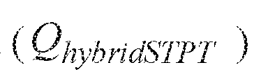
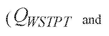
  • the hybrid- level power demand includes at least one of a hybrid-level active power demand
  • power demand set-points of the wind power generation system 102 and the PV power generation system 106 are determined based on the hybrid-level power demand.
  • the term "power demand set-point" is referred to as an amount of electrical power requirement from each of the wind power generation system 102 and the PV power generation system 106.
  • the power demand set-points include an active power demand set-point of the wind power generation system 102 and an active power demand set- point of the PV power generation system 106.
  • the hybrid controller 1 10 determines the active power demand set-points of the wind power generation system 102 and the PV power generation system 106 based on the hybrid-level active power demand Further
  • the power demand set-points include a reactive power demand set-point of the wind power generation system 102 and a reactive power demand set- point of the PV power generation system 106.
  • the hybrid controller 110 determines the reactive power demand set-points of the wind power generation system 102 and the PV power generation system 106 based on the hybrid-level reactive power demand
  • the hybrid controller 110 determines both the active power demand set-points and the reactive power demand set-points of the wind power generation system 102 and the PV power generation system 106. In some embodiments, the respective power demand set-points are determined such that the electrical power generated by the hybrid power generation system 100 does not lead to violation of predefined Balance of Plant (BoP) limits of the hybrid-level transformer 204.
  • the BoP limits include at least one of a maximum active power limit of the hybrid-level transformer 204, a maximum apparent power limit of the hybrid-level transformer 204, a maximum apparent current limit of the hybrid-level transformer 204, a maximum temperature limit of the hybrid-level transformer 204.
  • the power demand set-points of the wind power generation system 102 and the PV power generation system 106 are communicated respectively to of the wind power controller 104 and the PV power controller 108.
  • the active power demand set- point and/or the reactive power demand set-point of the wind power generation system 102 are communicated to the wind power controller 104 by the hybrid controller 110.
  • the active power demand set-point and/or the reactive power demand set-point of the PV power generation system 106 are communicated to the PV power controller 108 by the hybrid controller 110 for use in controlling operation of the wind power generation system 102 and the PV power generation system 106 for generation of an electrical power corresponding to the hybrid-level power demand
  • the wind power controller 104 and the PV power controller 108 may be operated in a master-slave configuration with one of the wind power controller or the PV power controller ac ting as the hybrid controller.
  • the wind power controller 104 is further configured to communicate, at step 406, the active power demand set- point and/or the reactive power demand set-point of the PV power generation system 106 to the PV power controller 108.
  • the PV power controller 108 is further configured to communicate, at step 406, the active power demand set-point and/or the reactive power demand set-point of the wind power generation system 102 to the wind power controller 104.
  • the power demand set-points are used by wind power controller 104 and the PV power controller 108 to control operation of the wind power generation system 102 and the PV power generation system 106 respectively for generation of the electrical power corresponding to the hybrid-level power demand.
  • the wind power controller 104 and the PV power controller 108 sends control signals respectively to the partial power converter 116 and the inverter 136 to control production of electrical power by the wind power generation system 102 and the PV power generation system 106.
  • FIG. 5 is a flow diagram 500 of a method for determining the hybrid-level power demand in accordance with the embodiment of FIG. 2.
  • the flow diagram 500 includes steps 502-512 that are representative of sub-steps of the step 402 of FIG. 4.
  • the hybrid-level power demand includes at least one of the hybrid-level active power demand and the hybrid-level reactive power demand
  • a power generation system such as the hybrid power generation
  • the system 100 has a rated active power which is dependent on power ratings of components of the hybrid power generation system 100.
  • the value of the rated active power of the hybrid power generation system 100 may be stored in a memory associated with the hybrid controller 110.
  • the hybrid-level active power demand is
  • the hybrid controller 110 determines the hybrid-level reactive power demand based on, for example, a measured voltage at an output of the hybrid power generation system 100 and a predefined range of voltage values.
  • a voltage is measured at the output of the hybrid power generation system 100. In one embodiment, the voltage is measured at the hybrid-level transformer 204.
  • the hybrid controller 110 determines the hybrid-level reactive power demand to be zero as indicated by step 510. If it is determined that the measured voltage
  • the hybrid controller 110 determines an amount of the reactive power to be supplied or consumed by the hybrid power generation system 100. Accordingly, at step 512, the hybrid-level reactive power demand
  • the hybrid-level reactive power demand is determined based on the amount of the reactive power needed to be supplied or consumed by the hybrid power generation 100. If the measured voltage at the output of the hybrid power generation system 100 is less than a lower limit of the predefined range of voltage values, the hybrid power generation system 100 supplies the reactive power to the power collection subsystem 202. In such an instance, the hybrid-level reactive power demand
  • representative of the reactive power to be supplied to the power collection sub-system 202 may be calculated using the following equation (1), for example: where, represents a hybrid power offset, represents a hybrid voltage multiplier,
  • the hybrid power generation system 100 consumes the reactive power from the power collection sub-system 202.
  • the reactive power to be consumed from the power collection sub-system 202 may be calculated using the following equation (2), for example: where, represents the upper limit of the predefined range of voltage values.
  • the reactive power to be supplied to the power collection sub-system 202 may be determined to be equal to In certain embodiments,
  • FIG. 6 is a flow diagram 600 of a method for determining hybrid-level power demand in in accordance with the embodiment of FIGs. 3 and 4.
  • the flow diagram 600 includes steps 602-608 that are representative of sub-steps of the step 402 of FIG . 4. More particularly, the flow diagram 600 is a method for determining hybrid-level active power demand The steps 602-608 are executed by the farm level supervisory controller 302 of FIG. 3.
  • step 602 farm level active power demand is determined by the
  • farm level supervisory controller 302. The farm level active power demand
  • farm level rated active power refers to a maximum active power production capacity of the farm 300.
  • the information of the farm level rated active power may be stored in a memory associated with the farm level supervisory controller
  • the farm level measured active power refers to an active power measured
  • the active power generated from the farm 300 is based on certain constraints or requirements such as the grid frequency constraint, power ramp-rate limit, and grid curtailment requirement.
  • the grid frequency constraint is representative of a grid frequency tolerance range requiring an output frequency of a voltage of the farm 300 to be in the grid frequency tolerance range.
  • the output active power of the farm 300 is adjusted (i.e., increased or decreased) depending on the grid frequency tolerance range.
  • Such an adjusted active power due to the grid frequency constraint is hereinafter referred to as a grid frequency limited active power
  • power ramp-rate limit is indicative of a constraint on a ramp-rate for increasing or decreasing output power of th e farm 300.
  • the output power of the farm 300 may not be varied beyond the power ramp-rate limit.
  • the output power of the farm 300 which is limited due to the power ramp-rate limit, is referred to as a ramp-rate limited power
  • there are instructions i.e., the grid curtailment requirement
  • the grid curtailment requirement i.e., the grid curtailment requirement
  • the farm level active power demand may be represented by following equation (3):
  • a check may be performed at step 604 to determine if the farm level active power demand is selected from any of the
  • the farm level supervisory controller 302 determines a hybrid-level active power demand as the rated active power of the given hybrid power generation system 100
  • farm level supervisory controller 302 is determines the hybrid-level active power demand of the hybrid power generation system 100 based on at least one of a possible active power production metric of the hybrid power generation system 100, a remaining life-time of the hybrid power generation system 100, and the farm level active power demand.
  • a possible active power production metric of the hybrid power generation system 100
  • a remaining life-time of the hybrid power generation system 100 of the farm level active power demand
  • the hybrid- level active power demand may be calculated using the following equation (4),
  • the farm-level active power distribution coefficient for a hybrid power generation system is determined based on the possible active power production metric of the hybrid power generation systems 100 in the farm 300.
  • the farm-level active power distribution coefficient is calculated using the
  • the farm-level active power distribution coefficient for the hybrid power generation system 100 is determined based on the possible active power production metric and the remaining life-time of the hybrid power generation systems 100 in the farm 300.
  • the farm-level active power distribution coefficient is calculated using the following equation (6):
  • hybrid controllers 110 to the farm level supervisory controller 302.
  • the hybrid controller 110 determines the possible active power production metric of the corresponding hybrid
  • FIG. 7 is a flow diagram 700 of another method for determining hybrid-level power demand in accordance with the embodiment of FIG. 3.
  • the flow diagram 700 includes steps 702-712 that are representative of sub-steps of the step 402 of FIG. 4. More particularly, the flow diagram 700 is representative of a method for determining hybrid-level reactive power demand
  • the farm level supervisory controller 302 receives at least one of a farm level reactive power requirement a farm level power factor set-point The farm level reactive power requirement and the farm level
  • the farm level supervisory controller 302 measures farm level voltage and/or farm level reactive power.
  • the farm level measured reactive power refers to a reactive power measured at the output, for example, current and potential transformer 212, of the farm 300.
  • a farm level power demand such as a farm level reactive power demand is determined by the farm level supervisory controller 302.
  • the farm level is determined by the farm level supervisory controller 302.
  • supervisory controller 302 determines the farm level reactive power demand
  • the farm level reactive power demand may be determined
  • farm level apparent power may be
  • the farm level supervisory controller 302 performs a check to determine whether the farm 300 should operate in a Q-priority mode.
  • the Q-priority mode is an operating mode of the farm 300 when the farm 300 is required to supply a reactive power to a grid.
  • the farm level supervisory controller 302 executes step 708.
  • the farm level supervisory controller 302 determines a farm level reactive power set-point as the farm
  • step 706 if it is determined that the farm 300 is not required to operate in the Q- priority mode, the farm level supervisory controller 302 executes step 710. At step 710, the farm level supervisory controller 302 determines the farm level reactive power set-point based on a farm level possible reactive power metric and the
  • metric is representative of a possible reactive power which can be generated by
  • the farm level possible reactive power metric is equal to a sum of possible reactive power production metric corresponding to each of the hybrid power generation systems 100 of the farm 300. and is determined using following equation (10): [0069] In some embodiments, the farm level reactive power set-point is
  • the farm level supervisory controller 302 determines a hybrid-level reactive power demand The farm level supervisory controller 302 determines the hybrid-level reactive power demand based on the possible reactive power production metric corresponding to each of the hybrid power generation systems 100 in the farm 300
  • the farm-level reactive power distribution coefficient is calculated
  • FIG. 8 is a flow diagram 800 of a method for determining power demand set-points of the wind power generation system 102 and the P V power generation system 106 in the hybrid power generation system 100 in accordance with the embodiment of FIGS. 1-3.
  • the method includes steps 802, 804 that are representative of sub-steps of the step 404 of FIG. 4.
  • the power demand set-points include the active power demand set-points and/or the reactive power demand set-points of the wind power generation system 102 and the PV power generation system 106. More particularly, the method includes steps for determining active power demand set-points corresponding to the wind power generation system 102 and the PV power generation system 106.
  • step 802 a hybrid-level active power set-point is calculated.
  • the hybrid-level active power set-point is determined by the hybrid controller 110 based on at least one of the hybrid-level active power demand an effective active power producible by the hybrid power generation system 100, rated
  • the hybrid-level active power demand may be determined
  • the hybrid controller 110 at step 502 of FIG. 5.
  • the hybrid-level active power demand may be determined by the farm level supervisory controller 302 at step 608 of FIG. 6.
  • the effective active power is determined using
  • the hybrid-level active power set-point is calculated using
  • the hybrid controller 110 calculates the active power demand set-points of the wind power generation system 102 and the PV power generation system 106. In some embodiments, the hybrid controller 110 calculates the active power demand set-points based on a selected power regulation mode.
  • the power regulation mode may be any of a possible power mode, a tariff mode, or speed regulation mode.
  • the selection of the power regulation mode is pre-configured. In some embodiments, the selection of the power regulation mode is performed by an operator.
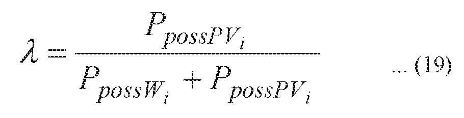
  • the active power demand set-points of the wind power generation system 102 and the PV power generation system 106 are determined based on possible active power production metrics, for example, a possible active wind-power production metric of the wind power generation system 102, a possible active PV-power production metric of the PV power generation system 106, and the
  • the possible active power production metric is referred to as an
  • the possible active wind-power production metric is calculated by
  • the hybrid controller 110 based on an estimated wind velocity.
  • the wind velocity may be estimated by the hybrid controller 110 based on at least one of a wind-turbine power, rotor speed, pitch angle of turbine blades, using a Kalman filter or extended Kalman filter. Further, a table having a mapping between the estimated wind velocity and different values of the possible active wind-power production metric is stored in the memory associated
  • the hybrid controller 110 determines the possible active wind- power production metric based on the mapping between the estimated wind
  • the possible active power production metric is referred to as an
  • the possible active PV-power production metric is determined by the hybrid controller 110 based on at least one of the
  • the hybrid controller 110 estimates the solar insolation based on at least one of voltage and current characteristics of the PV power source, the ambient temperature, and the air density. Further, the hybrid controller 110 determines the possible active PV-power production metric based on the estimated solar
  • the hybrid controller 110 calculates the active power demand set-points of the wind power generation system 102 and the PV power generation system 106 based on the possible active power production metrics and the hybrid-level active power demand set-point
  • the active power demand set-point of the wind is the active power demand set-point of the wind
  • the active power demand set-points of the wind power generation system 102 and the PV power generation system 106 are determined based on the wind power tariff and the PV power tariff.
  • the hybrid controller 110 determines the active power demand set-points such that
  • the hybrid controller 110 determines the active power demand set-points
  • the active power demand set-point of the PV power generation system 106 is calculated by the following equation (20) and the active power demand set-point of the PV power generation system 106 is calculated by the
  • generation system 102 is representative of a measured active power at an output of the PV power
  • wind active power is not sufficient. For example, is determined using
  • the hybrid controller 110 detennines the active power demand set-points
  • the active power demand set-points is
  • PV active power is not sufficient. For example, is determined using
  • the rotational speed of the rotor of the wind turbine is controlled in such a way that the electrical power from the wind power generation system 102 is not over curtailed.
  • the active power demand set-points are calculated using by the following equations (26, 27):
  • FIG. 9 is a flow diagram 900 of a method for determining power demand set-points of the wind power generation system 102 and the PV power generation system 106 in the hybrid power generation system 100 in accordance with the embodiments of FIGS. 1 -3.
  • the flow diagram 900 includes steps 902 and 904 that are representative of sub-steps of the step 404 of FIG. 4. More particularly, the includes steps for determining reactive power demand set-points of the wind power generation system 102 and the PV power generation system 106.
  • the hybrid-level reactive power set-point is determined.
  • the hybrid controller 110 based on at least one of the hybrid-level reactive power demand an effective reactive power producible by the hybrid power generation
  • the hybrid-level reactive power set-point is
  • the hybrid-level reactive power demand may be determined by the hybrid controller 110 at steps 510 or 512 of FIG. 5. In another embodiment, the hybrid-level reactive power demand may be
  • the effective reactive power is determined using following equation
  • the hybrid controller 110 is configured to calculate the reactive power demand set-points corresponding to the wind power generation system 102 and the PV power generation system 106. In some embodiments, the hybrid controller 110 is configured to calculate the reactive power demand set-points based on the selected power regulation mode described hereinabove.
  • the reactive power demand set-points of the wind power generation system 102 and the PV power generation system 106 are determined based on possible reactive power production metrics, for example, a possible reactive wind-power production metric of the wind power generation system 102, a possible reactive PV-power production metric of the PV power generation system 106, and the hybrid-level reactive power demand set-point
  • the possible reactive power production metric is referred to as
  • the possible reactive wind-power production metric is
  • the hybrid controller 110 calculates the total wind velocity based on an estimated wind velocity.
  • the wind velocity is estimated by the hybrid controller 110 based on at least one of a wind-turbine power, rotor speed, pitch angle of the turbine blades, using Kalman filter or extended Kalman filter. Further, a table having a mapping between the estimated wind velocity and different values of the possible reactive wind-power production metric is stored in the memory
  • the hybrid controller 110 determines the possible reactive wind-power production metric based on the mapping between the
  • the possible reactive power production metric is referred to as
  • the possible reactive PV-power production metric is determined by the hybrid controller 110 based on at least one of the
  • the hybrid controller 110 is configured to estimate the solar insolation based on one or more of voltage and current characteristics of the PV power source, the ambient temperature, the air density. Further, the hybrid controller 110 may determine the possible reactive PV-power production metric based on the
  • the hybrid controller 110 calculates the reactive power demand set-points of the wind power generation system 102 and the PV power generation system 106 based on the possible reactive power production metrics and the hybrid-level
  • PV power generation system 106 is calculated using following equation (32): where is calculated using the following equation (33):
  • the reactive power demand set-points of the wind power generation system 102 and the PV power generation system 106 are determined based on the wind power tariff and the PV power tariff.
  • the hybrid controller 110 determines the reactive power demand set-points such that reactive power from the power generation system having lower tariff is curtailed.
  • the hybrid controller 110 determines the reactive power demand set-points
  • the hybrid controller 110 determines the reactive power demand set-points
  • the reactive power demand set-points are
  • curtailment of the PV reactive power is not sufficient.
  • curtailment of the PV reactive power is not sufficient.
  • any of the foregoing steps may be suitably replaced, reordered, or removed, and additional steps may be inserted, depending on the needs of an application.
  • coordination between a hybrid controller and a farm level supervisory controller facilitates to distribute power demands among a plurality of hybrid power generation systems such that power demand of the farm is satisfied.
  • use of possible power production metrics for distribution of the active and reactive power demands leads to balanced distribution of power demand among the hybrid power generation systems.
  • use of possible power production metrics for distribution of the active and reactive power demands also leads to balanced distribution of the power demand between the wind power generation system and the PV power generation system within each hybrid power generation system.

Landscapes

  • Engineering & Computer Science (AREA)
  • Power Engineering (AREA)
  • Life Sciences & Earth Sciences (AREA)
  • Sustainable Development (AREA)
  • Sustainable Energy (AREA)
  • Supply And Distribution Of Alternating Current (AREA)

Abstract

A method and a system (111) for operating a hybrid power generation system (100) are presented, the hybrid power generation system (100) includes a wind power generation system (102), a wind power controller (104), a photo-voltaic (PV) power generation system, and a PV power controller (108). The method includes determining a hybrid-level power demand of the hybrid power generation system (100). The method further includes determining respective power demand set-points of the wind power generation system (102) and the PV power generation system (106) based at least in pail on the hybrid-level power demand. The method also includes communicating the power demand set-points of the wind power generation system (102) and the PV power generation system (106) respectively to at least one of the wind power controller (104) and the PV power controller (108). A farm (300) having a farm level control system (304) is also presented.

Description

METHOD AND SYSTEM FOR OPERATING A HYBRID POWER GENERATION
SYSTEM
BACKGROUND
[0001] Embodiments of the present invention generally relate to a hybrid power generation system and in particular, to method and system for operating a hybrid power generation system.
[0002] A wind based power generation is capable of converting kinetic energy of wind into electrical power. Currently, wind farms having different configurations are used to generate electrical power. Such farms may include wind turbine stations operable at a fixed speed, wind turbine stations performing full power conversion, and wind turbine stations performing partial power conversion. Additionally, solar/photo-voltaic (PV) based power generation systems may be used to generate electrical power based on solar irradiance.
[0003] For some applications, hybrid power generation systems are used. For example, such a hybrid power generation system includes both wind based power generation system and solar/photo-voltaic (PV) based power generation system to generate electrical power. The wind based power generation system and solar/photo-voltaic (PV) based power generation system generally share common balance of plant equipment (for example, a transformer). Typically, the wind based power generation system and the PV based power generation system are operated by respective controllers which operate independently of each other. In a hybrid power generation system, a net power generated by the wind based power generation system and the PV based power generation system needs to be lower than or equal to the maximum plant power limit of the hybrid power generation system. The maximum plant power limit can be determined by various factors such as the maximum rating of the balance of plant, curtailment, etc. Violating the maximum power limit may cause fluctuations in electrical power generated by the hybrid power generation system.
BRIEF DESCRIPTION
[0004] In accordance with one embodiment of the present invention, a method for operating a hybrid power generation system is presented. The hybrid power generation system includes a wind power generation system coupled to a wind power controller and a photovoltaic (PV) power generation system coupled to a PV power controller. The method includes determining a hybrid-level power demand of the hybrid power generation system . The method further includes determining respective power demand set-points of the wind power generation system and the PV power generation system based at least in part on the hybrid-level power demand. Furthermore, the method includes communicating the power demand set-points of the wind power generation system and the PV power generation system respectively to at least one of the wind power controller and the PV power controller for use in controlling operation of the wind power generation system and the PV power generation system for generation of an electrical power corresponding to the hybrid-level power demand.
[0005] In accordance with one embodiment of the present invention, a hybrid level control system for operating a hybrid power generation system is presented. The hybrid power generation system includes a wind power generation system and a PV power generation system. The hybrid level control system includes a wind power controller operably coupled to the wind power generation system. The hybrid level control system further includes a PV power controller operably coupled to the PV power generation system. The hybrid level control system also includes a hybrid controller operatively coupled to the wind power controller and the PV power controller, integrated within the wind power controller and operably coupled to the PV power controller, or integrated within the PV power controller and operably coupled to the wind power controller. The hybrid controller is configured to determine a hybrid-level power demand of the hybrid power generation system. The hybrid controller is further configured to determine respective power demand set-points of the wind power generation system and the PV power generation system based at least in part on the hybrid-level power demand. Furthermore, the hybrid controller is configured to provide the power demand set-points of the wind power generation system and the P V power generation system respectively to the wind power controller and the PV power controller for use in controlling operation of the wind power generation system and the PV power generation system for generation of an electrical power corresponding to the hybrid-level power demand.
[0006] In accordance with one embodiment of the present invention, a farm level control system for operating a farm is presented. The farm includes a plurality of hybrid power generation systems. The farm level control system includes hybrid controllers, each operatively coupled to a corresponding one of the plurality of hybrid power generation systems. The farm level control system further includes a farm level supervisory controller operatively coupled to the hybrid controllers. The farm level supervisory controller is configured to determine a farm level power demand. The farm level supervisory controller is further configured to calculate a hybrid-level power demand of each of the hybrid power generation systems based on at least one of the farm level power demand and at least one of a respective rated power, a respective possible power production metric, and a respective remaining lifetime of each respective hybrid power generation system hybrid power generation systems. Furthermore, the farm level supervisory controller is configured to communicate the hybrid- level power demands to the respective hybrid controllers to enable generation of an electrical power by the hybrid power generation systems corresponding to the hybrid-level power demand.
DRAWINGS
[0007] These and other features, aspects, and advantages of the present specification will become better understood when the following detailed description is read with reference to the accompanying drawings in which like characters represent like parts throughout the drawings, wherein:
[0008] FIG. 1 is a block diagram representation of a hybrid power generation system in accordance with one embodiment of the present invention;
[0009] FIG. 2 is a block diagram representation of a farm having a plurality of hybrid power generation systems in accordance with one embodiment of the present invention;
[0010] FIG. 3 is a block diagram representation of a farm having a plurality of hybrid power generation systems in accordance with another embodiment of the present invention;
[0011] FIG. 4 is a flow diagram of a method for operating a hybrid power generation system in accordance with one embodiment of the present invention;
[0012] FIG. 5 is a flow diagram of a method for determining a hybrid-level power demand in accordance with the embodiment of FIG. 2;
[0013] FIG. 6 is a flow diagram of a method for determining a hybrid-level power demand in the configuration of the farm of FIG. 3, in accordance with the embodiment of FIG. 3;
[0014] FIG. 7 is a flow diagram of a method for determining hybrid-level power demand in accordance with the embodiment of FIG. 3; [0015] FIG. 8 is a flow diagram of a method for determining power demand set-points of a wind power generation system and a PV power generation system of a hybrid power generation system in accordance with one embodiment of the present invention; and
[0016] FIG. 9 is a flow diagram of a method for determining power demand set-points of a wind power generation system and a PV power generation system of a hybrid power generation system in accordance with one embodiment of the present invention.
DETAILED DESCRIPTION
[0017] As used herein, the terms "may" and "may be" indicate a possibility of an occurrence within a set of circumstances; a possession of a specified property, characteristic or function; and/or qualify another verb by expressing one or more of an ability, capability, or possibility associated with the qualified verb. Accordingly, usage of "may" and "may be" indicates that a modified term is apparently appropriate, capable, or suitable for an indicated capacity, function, or usage, while taking into account that in some circumstances, the modified term may sometimes not be appropriate, capable, or suitable.
[0018] In accordance with some embodiments of the present invention, a method for operating a hybrid power generation system is presented. The hybrid power generation system includes a wind power generation system coupled to a wind power controller and a photovoltaic (PV) power generation system coupled to a PV power controller. The method includes determining a hybrid-level power demand of the hybrid power generation system. The method further includes determining respective power demand set-points of the wind power generation system and the PV power generation system based at least in part on the hybrid-level power demand. Furthermore, the method includes communicating the power demand set-points of the wind power generation system and the PV power generation system respectively to at least one of the wind power controller and the PV power controller. Moreover, the method also includes using the power demand set-points of the wind power controller and the PV power controller to control operation of the wind power generation system and the PV power generation system for generation of an electrical power corresponding to the hybrid-level power demand. In accordance with some embodiments of the present invention, a hybrid level control system for operating the hybrid power generation system and a farm level control system for operating the farm are also presented. [0019] FIG. 1 is a block diagram representation of a hybrid power generation system 100 in accordance with one embodiment of the present invention. The hybrid power generation system 100 includes a wind power generation system 102, a wind power controller 104 operatively coupled to the wind power generation system 102, a photo-voltaic (PV) power generation system 106, a PV power controller 108 operatively coupled to the PV power generation system 106, and a hybrid controller 110. In the illustrated embodiment, the wind power controller 104, the P V power controller 108, and the hybrid controller 110 together form a hybrid level control system 111. In the embodiment of FIG. 1, the hybrid controller 110 is operatively coupled to the wind power controller 104 and the PV power controller 108. In some embodiments, the hybrid controller 110 may be integrated within the wind power controller 104 and operably coupled to the PV power controller 108. In certain embodiments, the hybrid controller 1 10 may be integrated within the PV power controller 108 and operably coupled to the wind power controller 104.
[0020] The hybrid power generation system 100 is configured to generate an alternating current (AC) electrical power and supply the AC electrical power from an output power port 112 of the hybrid power generation system 100. The AC electrical power at the output power port 112 may be single phase or multi-phase such as three- phase electrical power. Moreover, the AC electrical power generated by the hybrid power generation system 100 includes a hybrid-level active power and a hybrid-level reactive power.
[0021] The wind power generation system 102 may include, for example, a generator such as a doubly-fed induction generator (DFIG) 114 and a partial power converter 116 electrically coupled to the DFIG 114. The DFIG 114 includes a stator 118, a rotor 120, a stator winding 122 wound on the stator 118, and a rotor winding 124 wound on the rotor 120. In some embodiments, both the stator winding 122 and the rotor winding 124 may be multi-phase winding such as a three-phase winding. Although, the wind power generation system 102 having the DFIG 114 is shown in FIG. 1, a wind power generation system having other synchronous or asynchronous generator may also be used without limiting the scope of the present invention.
[0022] The DFIG 114 is mechanically coupled to a wind-turbine (not shown). For example, the rotor 120 of the DFIG 114 is mechanical ly coupled to a rotor of the wind-turbine such that rotations of the ro tor of the wind-turbine cause rotations of the rotor 120 of the DFIG 114. The rotor 120 of the DFIG 114 is operated at a rotational speed which can be a synchronous speed, a sub-synchronous speed, or a super-synchronous speed depending on the wind speed and a slip value of the DFIG 114. During operation, the DFIG 114 is configured to generate electrical power at the stator winding 122. Further, the DFIG 114 is configured to generate or absorb electrical power at the rotor winding 124 depending on the rotational speed of the rotor 120. For example, the DFIG 114 is configured to generate electrical power at the rotor winding 124 when the rotor 120 is operated at a super-synchronous speed. The DFIG 114 is configured to absorb the electrical power at the rotor winding 124 when the rotor 120 is operated at a sub-synchronous speed. At a synchronous speed, no power is absorbed or generated at the rotor winding 124.
[0023] The partial power converter 1 16 i s electrically coupled to the rotor winding 124 and the stator winding 122. The partial power converter 116 includes a rotor-side converter 126 and a line-side converter 128. The rotor-side converter 126 is electrically coupled to the rotor winding 124 of the DFIG 114. The line-side converter 128 is electrically coupled directly or via a transformer to the stator winding 122 of the DFIG 1 14. The rotor-side converter 126 and the line-side converter 128 are electrically coupled to each other via a DC-link 130. The rotor- side converter 126 may be an AC-DC converter and configured to convert an AC power into a DC power. In another embodiment, the rotor-side converter 126 may be a DC- AC converter. The line-side converter 128 may be a DC-AC converter and configured to convert the DC power into an AC power. In another embodiment, the line-side converter 128 may be a AC- DC converter.
[0024] Further, the stator winding 122 is coupled to an output electrical node 132 of the wind power generation system 102. In some embodiments, the stator winding 122 is coupled to an output electrical node 132 via a transformer (not shown). Further, the line-side converter 128 is coupled to the output electrical node 132 via a transformer (not shown). The power generated at the stator winding 122, is supplied directly or via the line-side converter to the output electrical node 132. When the rotor 120 is operated at a super-synchronous speed, the power generated at the rotor winding 124, is supplied to the output electrical node 132 via the partial power converter 116. The electrical power at the output electrical node 132 is equal to a sum of the electrical power received from the stator winding 122 and the rotor winding 124. The wind power generation system 102 supplies the generated electrical power to the output power port 112 via the output electrical node 132.
[0025] The wind power controller 104 is operatively coupled to the rotor-side converter 126 and the line-side converter 128 and configured to send control signals to the rotor-side converter 126 and the line-side converter 128 to control respective operations. More particularly, the wind power controller 104 sends the control signals to the rotor-side converter 126 and the line-side converter 128 based at least in part on instructions/control signals received from the hybrid controller 110.
[0026] The PV power generation system 106 includes a PV power source 134 and an inverter 136 coupled to the PV power source 134. The PV power source 134 includes one or more PV arrays (not shown), where each PV array may include at least one PV module (not shown). A PV module includes a suitable arrangement of a plurality of PV cells. The PV power source 134 is configured to supply the electrical power to the inverter 136. The inverter 136 is configured to convert the DC power received from the PV power source 134 into an AC power at an output electrical node 138 of the PV power generation system 106. The output electrical node 138 of the PV power generation system 106 is electrically coupled to the output electrical node 132 of the wind power generation system 106.
[0027] The PV power controller 108 is operatively coupled to the inverter 136 and configured to send control signals to the inverter 136 to control operation of the inverter 136. More particularly, the PV power controller 108 sends the control signals to the inverter 136 based at least in part on instructions/control signals received from the hybrid controller 110.
[0028] The hybrid controller 1 10 is configured to send control signals to the wind power controller 104 and the PV power controller 108 to control electrical power generated by the wind power generation system 102 and the PV power generation system 106. More particularly, the hybrid controller 110 is configured to communicate control signals to the wind power controller 104 and the PV power controller 108 to control production of the active and/or reactive electrical power by the wind power generation system 102 and the PV power generation system 106. Further details of the operations performed by the hybrid controller 110 are described in conjunction with methods of FIGS. 4, 5, 8, and 9. [0029] In some embodiments, at least one among the wind power controller 104, the PV power controller 108, and the hybrid controller 110 may include a specially programmed general purpose computer, an electronic processor such as a microprocessor, a digital signal processor, and/or a microcontroller. Further, at least one of the wind power controller 104, the PV power controller 108, and the hybrid controller 1 10 may include input/output ports, and a storage medium, such as an electronic memory. Various examples of the microprocessor include, but are not limited to, a reduced instruction set computing (RISC) architecture type microprocessor or a complex instruction set computing (CISC) architecture type microprocessor. Further, the microprocessor may be a single-core type or multi-core type. Alternatively, at least one of the wind power controller 104, the PV power controller 108, and the hybrid controller 110 may be implemented as hardware elements such as circuit boards with processors or as software running on a processor such as a commercial, off-the-shelf personal computer (PC), or a microcontroller.
[0030] FIG. 2 is a block diagram representation of a farm 200 having a plurality of hybrid power generation systems 100 in accordance with one embodiment of the present invention. The farm 200 may be electrically coupled to an electric grid (not shown) and/or local electrical load (not shown) and configured to supply electrical power thereto.
[0031] Although, two hybrid power generation systems 100 are shown in FIG.2, the number of hybrid power generation systems 100 may vary depending on the application.
[0032] The farm 200 additionally includes a power collection sub-system 202 electrically coupled to the plurality of hybrid power generation systems 100. The output power port 112 of each of the plurality of hybrid power generation systems 100 is coupled to the power collection sub-system 202 via a hybrid-level transformer 204 (also referred to as a pad-mount transformer) and a switch 206. The switch 206 is operated to selectively connect or disconnect the respective hybrid power generation system 100. In some embodiments, the switch 206 may be electronically controllable by the hybrid controller 110 of the respective hybrid power generation system 100. In certain other embodiments, the switch 206, may be controlled manually. The electrical power generated by the hybrid power generation systems 100 is supplied to the power collection sub-system 202 via the respective hybrid-level transformer 204 and the switch 206. [0033] The power collection sub-system 202 includes a power bus 208, a sub-station transformer 210 coupled to the power bus 208, and a current and potential transformer (CTPT) 212 coupled to the sub-station transformer 210. The power bus 208 is electrically coupled to the output power port 112 of each of the plurality of hybrid power generation systems 100 to receive electrical power therefrom.
[0034] FIG. 3 is a block diagram representation of a farm 300 having the plurality of hybrid power generation systems 100 in accordance with another embodiment of the present invention. The farm 300 is similar to the embodiment of FIG. 2, except that the farm 300 additionally includes a farm level supervisory controller 302. In the illustrated embodiment, the farm level supervisory controller 302 and the hybrid level control system 111 of each of the hybrid power generation systems 100, form a farm level control system 304.
[0035] In some embodiments, the farm level supervisory controller 302 includes a specially programmed general purpose computer, an electronic processor such as a microprocessor, a digital signal processor, and/or a microcontroller. The farm level supervisory' controller 302 may include input/output ports, and a storage medium, such as an electronic memory. Various examples of the microprocessor include, but are not limited to, a reduced instruction set computing (RISC) architecture type microprocessor or a complex instruction set computing (CISC) architecture type microprocessor. Further, the microprocessor may be a single-core type or multi-core type. Alternatively, the farm level supervisory controller 302 may be implemented as hardware elements such as circuit boards with processors or as software running on a processor such as a commercial, off-the-shelf personal computer (PC), or a microcontroller.
[0036] The farm level supervisory controller 302 is operatively coupled to the hybrid controller 110 of each of the plurality of hybrid power generation systems 100 and the current and potential transformer 212. The farm level supervisory controller 302 is configured to send control signals to the hybrid controllers 110 to control production of electrical power by the respective hybrid power generation systems 100. More particularly, the farm level supervisory controller 302 is configured to send control signals to the hybrid controllers 110 to control production of active and/or reactive electrical power by the respective hybrid power generation systems 100. Further details of the operation performed by the farm level supervisory controller 302 are described in conjunction with methods described below with reference to FIGS. 6 and 7.
[0037] FIG. 4 is a flow diagram 400 of a method for operating the hybrid power generation system 100 in accordance with the embodiment of FIG. 1. The method includes steps 402- 408.
[0038] At step 402, a hybrid-level power demand of the hybrid power generation 100 is determined. In some embodiments, the hybrid controller 110 is configured to determine the hybrid-level power demand. The term "hybrid-level power demand" is referred to as a quantity of electrical power requirement from the hybrid power generation system 100. The hybrid- level power demand includes at least one of a hybrid-level active power demand
Figure imgf000012_0001
and a hybrid-level reactive power demand Further, details of determining
Figure imgf000012_0002
the hybrid-level active and/or reactive power demands are described in conjunction with FIGS. 5, 6, and 7.
[0039] Further, at step 404, power demand set-points of the wind power generation system 102 and the PV power generation system 106 are determined based on the hybrid-level power demand. The term "power demand set-point" is referred to as an amount of electrical power requirement from each of the wind power generation system 102 and the PV power generation system 106.
[0040] In some embodiments, the power demand set-points include an active power demand set-point of the wind power generation system 102 and an active power demand set- point of the PV power generation system 106. The hybrid controller 1 10 determines the active power demand set-points of the wind power generation system 102 and the PV power generation system 106 based on the hybrid-level active power demand Further
Figure imgf000012_0003
details of determining the active power demand set-points of the wind power generation system 102 and the PV power generation system 106 are described below with reference to FIG. 8.
[0041] In some embodiments, the power demand set-points include a reactive power demand set-point of the wind power generation system 102 and a reactive power demand set- point of the PV power generation system 106. The hybrid controller 110 determines the reactive power demand set-points of the wind power generation system 102 and the PV power generation system 106 based on the hybrid-level reactive power demand
Figure imgf000013_0001
Further details of determining the reactive power demand set-points of the wind power generation system 102 and the PV power generation system 106 are described in detail with reference to FIG. 9.
[0042] In some embodiments, the hybrid controller 110 determines both the active power demand set-points and the reactive power demand set-points of the wind power generation system 102 and the PV power generation system 106. In some embodiments, the respective power demand set-points are determined such that the electrical power generated by the hybrid power generation system 100 does not lead to violation of predefined Balance of Plant (BoP) limits of the hybrid-level transformer 204. The BoP limits include at least one of a maximum active power limit of the hybrid-level transformer 204, a maximum apparent power limit of the hybrid-level transformer 204, a maximum apparent current limit of the hybrid-level transformer 204, a maximum temperature limit of the hybrid-level transformer 204.
[0043] At step 406, the power demand set-points of the wind power generation system 102 and the PV power generation system 106 are communicated respectively to of the wind power controller 104 and the PV power controller 108. For example, the active power demand set- point and/or the reactive power demand set-point of the wind power generation system 102 are communicated to the wind power controller 104 by the hybrid controller 110. Similarly, the active power demand set-point and/or the reactive power demand set-point of the PV power generation system 106 are communicated to the PV power controller 108 by the hybrid controller 110 for use in controlling operation of the wind power generation system 102 and the PV power generation system 106 for generation of an electrical power corresponding to the hybrid-level power demand
Figure imgf000013_0002
[0044] In some embodiments, the wind power controller 104 and the PV power controller 108 may be operated in a master-slave configuration with one of the wind power controller or the PV power controller ac ting as the hybrid controller. For example, in an embodiment, if the wind power controller 104 is configured to execute the steps 402, 404, the wind power controller 104 is further configured to communicate, at step 406, the active power demand set- point and/or the reactive power demand set-point of the PV power generation system 106 to the PV power controller 108. In another embodiment, if the PV power controller 108 is configured to execute the steps 402, 404, the PV power controller 108 is further configured to communicate, at step 406, the active power demand set-point and/or the reactive power demand set-point of the wind power generation system 102 to the wind power controller 104.
[0045] At step 408, the power demand set-points are used by wind power controller 104 and the PV power controller 108 to control operation of the wind power generation system 102 and the PV power generation system 106 respectively for generation of the electrical power corresponding to the hybrid-level power demand. For example, the wind power controller 104 and the PV power controller 108 sends control signals respectively to the partial power converter 116 and the inverter 136 to control production of electrical power by the wind power generation system 102 and the PV power generation system 106.
[0046] FIG. 5 is a flow diagram 500 of a method for determining the hybrid-level power demand in accordance with the embodiment of FIG. 2. The flow diagram 500 includes steps 502-512 that are representative of sub-steps of the step 402 of FIG. 4.
[0047] As previously noted, the hybrid-level power demand includes at least one of the hybrid-level active power demand and the hybrid-level reactive power demand
Figure imgf000014_0002
Typically, a power generation system such as the hybrid power generation
Figure imgf000014_0001
system 100 has a rated active power which is dependent on power ratings of components of the hybrid power generation system 100. In one embodiment, the value of the rated active power of the hybrid power generation system 100 may be stored in a memory associated with the hybrid controller 110. At step 502, the hybrid-level active power demand is
Figure imgf000014_0003
determined to be the rated active power of the hybrid power generation system 100.
[0048] In some embodiments, additionally or alternatively, at step 504, the hybrid controller 110 determines the hybrid-level reactive power demand based on,
Figure imgf000014_0004
for example, a measured voltage at an output of the hybrid power generation system 100 and a predefined range of voltage values. At step 506, a voltage is measured at the output of the hybrid power generation system 100. In one embodiment, the voltage is measured at the hybrid-level transformer 204.
[0049] Typically, it is desirable that the measured voltage at the output of the hybrid power generation system 100 is maintained within the predefined range of voltage values to ensure generation of stable voltage. Accordingly, a check may be performed at step 508 to determine whether the measured voltage is within the predefined range of voltage values. If it is determined that the measured voltage is within the predefined range of voltage values, in one embodiment, the hybrid controller 110 determines the hybrid-level reactive power demand
Figure imgf000015_0002
to be zero as indicated by step 510. If it is determined that the measured voltage
Figure imgf000015_0001
is not within the predefined range of voltage values, the hybrid controller 110 determines an amount of the reactive power to be supplied or consumed by the hybrid power generation system 100. Accordingly, at step 512, the hybrid-level reactive power demand
Figure imgf000015_0003
is determined based on the amount of the reactive power needed to be supplied or consumed by the hybrid power generation 100. If the measured voltage at the output of the hybrid power generation system 100 is less than a lower limit of the predefined range of voltage values, the hybrid power generation system 100 supplies the reactive power to the power collection subsystem 202. In such an instance, the hybrid-level reactive power demand
Figure imgf000015_0004
representative of the reactive power to be supplied to the power collection sub-system 202 may be calculated using the following equation (1), for example:
Figure imgf000015_0005
where, represents a hybrid power offset, represents a hybrid voltage multiplier,
Figure imgf000016_0003
represents the lower limit of the predefined range of voltage values, and represents the
Figure imgf000016_0004
measured voltage at the output of the hybrid power generation system 100.
[0050] If the measured voltage at the output of the hybrid power generation system 100 is greater than an upper limit of the predefined range of voltage values, the hybrid power generation system 100 consumes the reactive power from the power collection sub-system 202.
In such an instance, the hybrid-level reactive power demand representative of
Figure imgf000016_0005
the reactive power to be consumed from the power collection sub-system 202 may be calculated using the following equation (2), for example:
Figure imgf000016_0001
where, represents the upper limit of the predefined range of voltage values.
Figure imgf000016_0007
[0051] In some embodiments, when the measured voltage at the output of the hybrid power generation system 100 is within the predefined range of voltage values, the reactive power to be supplied to the power collection sub-system 202 may be determined to be equal to In
Figure imgf000016_0006
certain embodiments,
Figure imgf000016_0008
[0052] FIG. 6 is a flow diagram 600 of a method for determining hybrid-level power demand in in accordance with the embodiment of FIGs. 3 and 4. The flow diagram 600 includes steps 602-608 that are representative of sub-steps of the step 402 of FIG . 4. More particularly, the flow diagram 600 is a method for determining hybrid-level active power demand
Figure imgf000016_0002
The steps 602-608 are executed by the farm level supervisory controller 302 of FIG. 3.
[0053] At step 602, farm level active power demand is determined by the
Figure imgf000016_0009
farm level supervisory controller 302. The farm level active power demand
Figure imgf000016_0010
is detennined based on at least one of a farm level rated active power
Figure imgf000017_0001
a farm level measured active power and one or more constraints such as but not
Figure imgf000017_0002
limited to, a grid frequency constraint, a power ramp-rate limit, and a grid curtailment requirement. The term "farm level rated active power" refers to a maximum active power production capacity of the farm 300. The information of the farm level rated active power
Figure imgf000017_0004
may be stored in a memory associated with the farm level supervisory controller
Figure imgf000017_0003
302. The farm level measured active power refers to an active power measured
Figure imgf000017_0005
at an output, for example, CTPT 212 of the farm 300.
[0054] In some embodiments, the active power generated from the farm 300 is based on certain constraints or requirements such as the grid frequency constraint, power ramp-rate limit, and grid curtailment requirement. The grid frequency constraint is representative of a grid frequency tolerance range requiring an output frequency of a voltage of the farm 300 to be in the grid frequency tolerance range. The output active power of the farm 300 is adjusted (i.e., increased or decreased) depending on the grid frequency tolerance range. Such an adjusted active power due to the grid frequency constraint is hereinafter referred to as a grid frequency limited active power
Figure imgf000017_0006
[0055] The term "power ramp-rate limit" as used herein is indicative of a constraint on a ramp-rate for increasing or decreasing output power of th e farm 300. For example, the output power of the farm 300 may not be varied beyond the power ramp-rate limit. The output power of the farm 300 which is limited due to the power ramp-rate limit, is referred to as a ramp-rate limited power
Figure imgf000017_0007
[0056] In certain embodiments, there are instructions (i.e., the grid curtailment requirement) from a grid operator to limit the output power of the farm 300. In case the output power of the farm 300 is limited due to such grid curtailment requirement, such output power of the farm 300 is referred to as a grid curtailed power
Figure imgf000017_0008
[0057] Accordingly, in some embodiments, the farm level active power demand
Figure imgf000018_0003
Figure imgf000018_0001
may be represented by following equation (3):
Figure imgf000018_0002
[0058] Moreover, in some embodiments, a check may be performed at step 604 to determine if the farm level active power demand is selected from any of the
Figure imgf000018_0004
grid frequency limited active power the ramp-rate limited power
Figure imgf000018_0005
Figure imgf000018_0006
the grid curtailed power If it is determined that the farm level active
Figure imgf000018_0007
power demand is not selected from any of the grid frequency limited active
Figure imgf000018_0008
power the ramp-rate limited power the grid curtailed power
Figure imgf000018_0009
Figure imgf000018_0010
Figure imgf000018_0011
at step 606, the farm level supervisory controller 302 determines a
Figure imgf000018_0012
hybrid-level active power demand as the rated active power of the given hybrid
Figure imgf000018_0013
power generation system 100
Figure imgf000018_0014
[0059] If it is determined that the farm level active power demand is
Figure imgf000018_0015
selected from any of the grid frequency limited active power the ramp-rate
Figure imgf000018_0016
limited power the grid curtailed power at step 608, the
Figure imgf000018_0018
Figure imgf000018_0017
farm level supervisory controller 302 is determines the hybrid-level active power demand
Figure imgf000018_0019
of the hybrid power generation system 100 based on at least one of a possible
Figure imgf000018_0020
active power production metric of the hybrid power generation system 100, a
Figure imgf000018_0021
remaining life-time of the hybrid power generation system 100, and the farm level
Figure imgf000019_0001
active power demand The term "possible active power production metric"
Figure imgf000019_0002
of the hybrid power generation system 100 as used herein refers to an amount of an active power that can be possibly produced by the hybrid power generation system 100. The hybrid- level active power demand may be calculated using the following equation (4),
Figure imgf000019_0003
for example:
Figure imgf000019_0004
where represents a farm-level active power distribution coefficient and /' represents number of hybrid power generation systems 100 in the farm 300. For farm 300, I =1, 2.
[0060] In some embodiments, the farm-level active power distribution coefficient for
Figure imgf000019_0011
a hybrid power generation system is determined based on the possible active power production metric of the hybrid power generation systems 100 in the farm 300. In some
Figure imgf000019_0005
embodiments, the farm-level active power distribution coefficient is calculated using the
Figure imgf000019_0010
following equation (5):
Figure imgf000019_0006
Where, i = 1,2 for the farm 300.
[0061] In some embodiments, the farm-level active power distribution coefficient for
Figure imgf000019_0009
the hybrid power generation system 100 is determined based on the possible active power production metric and the remaining life-time of the hybrid power
Figure imgf000019_0007
Figure imgf000019_0008
generation systems 100 in the farm 300. The farm-level active power distribution coefficient is calculated using the following equation (6):
Figure imgf000020_0001
Where,
Figure imgf000020_0013
for the farm 300 and
Figure imgf000020_0014
[0062] The possible active power production metrics for the hybrid power
Figure imgf000020_0002
generation systems 100 are computed by the respective hybrid controllers 1 10. The values of the possible active power production metrics are communicated from the respective
Figure imgf000020_0003
hybrid controllers 110 to the farm level supervisory controller 302. The hybrid controller 110 determines the possible active power production metric of the corresponding hybrid
Figure imgf000020_0004
power generation system 100 based on a possible active wind-power production metric
Figure imgf000020_0005
and a possible active PV-power production metric The details of
Figure imgf000020_0006
Figure imgf000020_0007
computing the possible active wind-power production metric and the possible
Figure imgf000020_0008
active PV-power production metric are described in detail with reference to FIG.
Figure imgf000020_0009
8. The possible active power production metric of the corresponding hybrid power
Figure imgf000020_0010
generation system 100 is calculated using the following equation (7):
Figure imgf000020_0011
[0063] The hybrid-level active power demand once determined, is
Figure imgf000020_0012
communicated to the respective hybrid controllers 110 to enable generation of an electrical power by the hybrid power generation systems 100 corresponding to the hybrid-level power demand. [0064] FIG. 7 is a flow diagram 700 of another method for determining hybrid-level power demand in accordance with the embodiment of FIG. 3. In some embodiments, the flow diagram 700 includes steps 702-712 that are representative of sub-steps of the step 402 of FIG. 4. More particularly, the flow diagram 700 is representative of a method for determining hybrid-level reactive power demand
Figure imgf000021_0012
[0065] At step 702, the farm level supervisory controller 302 receives at least one of a farm level reactive power requirement a farm level power factor set-point
Figure imgf000021_0011
Figure imgf000021_0010
The farm level reactive power requirement and the farm level
Figure imgf000021_0008
Figure imgf000021_0009
power factor set-point are communicated to the farm level supervisor}' controller
Figure imgf000021_0007
302 and/or are stored in the memory associated with the farm level supervisory controller 302. Further, at step 704, the farm level supervisory controller 302 measures farm level voltage and/or farm level reactive power. The farm level measured reactive power refers to a reactive power measured at the output, for example, current and potential transformer 212, of the farm 300.
[0066] At step 705 , a farm level power demand such as a farm level reactive power demand is determined by the farm level supervisory controller 302. The farm level
Figure imgf000021_0006
supervisory controller 302 determines the farm level reactive power demand
Figure imgf000021_0005
based on at least one of the farm level reactive power requirement the farm
Figure imgf000021_0004
level power factor set-point and the farm level measured active power. In some
Figure imgf000021_0003
embodiments, the farm level reactive power demand may be determined
Figure imgf000021_0002
using following equation (8):
Figure imgf000021_0001
where, represents the farm level apparent power and represents the farm
Figure imgf000022_0004
Figure imgf000022_0002
level measured active power. Moreover, the farm level apparent power may be
Figure imgf000022_0003
calculated using following equation (9):
Figure imgf000022_0001
[0067] At step 706, the farm level supervisory controller 302 performs a check to determine whether the farm 300 should operate in a Q-priority mode. The Q-priority mode is an operating mode of the farm 300 when the farm 300 is required to supply a reactive power to a grid. At step 706, if it is determined that the farm 300 should operate in the Q-priority mode, the farm level supervisory controller 302 executes step 708. At step 708, the farm level supervisory controller 302 determines a farm level reactive power set-point as the farm
Figure imgf000022_0005
level reactive power demand
Figure imgf000022_0006
[0068] At step 706, if it is determined that the farm 300 is not required to operate in the Q- priority mode, the farm level supervisory controller 302 executes step 710. At step 710, the farm level supervisory controller 302 determines the farm level reactive power set-point
Figure imgf000022_0008
based on a farm level possible reactive power metric and the
Figure imgf000022_0009
Figure imgf000022_0007
farm level reactive power demand The farm level possible reactive power
Figure imgf000022_0010
metric is representative of a possible reactive power which can be generated by
Figure imgf000022_0011
the farm 300. In some embodiments, the farm level possible reactive power metric
Figure imgf000022_0012
is equal to a sum of possible reactive power production metric
Figure imgf000022_0013
Figure imgf000022_0014
corresponding to each of the hybrid power generation systems 100 of the farm 300. and is determined using following equation (10):
Figure imgf000022_0015
[0069] In some embodiments, the farm level reactive power set-point is
Figure imgf000023_0001
determined as minimum of the farm level possible reactive power metric
Figure imgf000023_0002
the farm level reactive power demand The farm level reactive power set-
Figure imgf000023_0003
point is determined using following equation (11):
Figure imgf000023_0004
Figure imgf000023_0005
[0070] After farm level reactive power set-point is determined, at step
Figure imgf000023_0006
712, the farm level supervisory controller 302, determines a hybrid-level reactive power demand The farm level supervisory controller 302 determines the hybrid-level
Figure imgf000023_0007
reactive power demand based on the possible reactive power production metric
Figure imgf000023_0008
corresponding to each of the hybrid power generation systems 100 in the farm 300
Figure imgf000023_0009
and the farm level reactive power set-point The hybrid-level reactive power
Figure imgf000023_0010
requirement is determined using following equation (12):
Figure imgf000023_0011
Figure imgf000023_0012
where, represents a farm-level reactive power distribution coefficient and i represents number of hybrid power generation systems 100 in the farm 300. For farm 300, I =1, 2.
[0071] The farm-level reactive power distribution coefficient for a hybrid power
Figure imgf000023_0015
generation system 100 is determined based on the possible reactive power production metric
Figure imgf000023_0014
corresponding to the hybrid power generation systems 100 in the farm 300. In
Figure imgf000023_0013
some embodiments, the farm-level reactive power distribution coefficient is calculated
Figure imgf000024_0002
using the following equation (13):
Figure imgf000024_0001
Where,
Figure imgf000024_0004
for the farm 300.
[0072] The hybrid-level reactive power demand once determined, is
Figure imgf000024_0003
communicated to the respective hybrid controllers 1 10 to enable generation of an electrical power by the hybrid power generation systems 100 corresponding to the hybrid-level power demand.
[0073] FIG. 8 is a flow diagram 800 of a method for determining power demand set-points of the wind power generation system 102 and the P V power generation system 106 in the hybrid power generation system 100 in accordance with the embodiment of FIGS. 1-3. The method includes steps 802, 804 that are representative of sub-steps of the step 404 of FIG. 4. As previously noted, the power demand set-points include the active power demand set-points and/or the reactive power demand set-points of the wind power generation system 102 and the PV power generation system 106. More particularly, the method includes steps for determining active power demand set-points corresponding to the wind power generation system 102 and the PV power generation system 106.
[0074] At step 802, a hybrid-level active power set-point is calculated.
Figure imgf000024_0005
The hybrid-level active power set-point is determined by the hybrid
Figure imgf000024_0006
controller 110 based on at least one of the hybrid-level active power demand an
Figure imgf000024_0007
effective active power producible by the hybrid power generation system 100, rated
Figure imgf000024_0008
active power of the hybrid power generation system 100. As noted earlier,
Figure imgf000024_0009
in one embodiment, the hybrid-level active power demand may be determined
Figure imgf000025_0002
by the hybrid controller 110 at step 502 of FIG. 5. In another embodiment, the hybrid-level active power demand may be determined by the farm level supervisory
Figure imgf000025_0003
controller 302 at step 608 of FIG. 6. The effective active power is determined using
Figure imgf000025_0004
following equation (14):
Figure imgf000025_0001
where represents a hybrid-level apparent power.
Figure imgf000025_0005
[0075] The hybrid-level active power set-point is calculated using
Figure imgf000025_0006
following equation (15):
[0076] At step 804, the hybrid controller 110 calculates the active power demand set-points of the wind power generation system 102 and the PV power generation system 106. In some embodiments, the hybrid controller 110 calculates the active power demand set-points based on a selected power regulation mode. For example, the power regulation mode may be any of a possible power mode, a tariff mode, or speed regulation mode. In one embodiment, the selection of the power regulation mode is pre-configured. In some embodiments, the selection of the power regulation mode is performed by an operator.
[0077] In the possible power mode, the active power demand set-points of the wind power generation system 102 and the PV power generation system 106 are determined based on possible active power production metrics, for example, a possible active wind-power production metric of the wind power generation system 102, a possible active
Figure imgf000025_0008
PV-power production metric of the PV power generation system 106, and the
Figure imgf000026_0002
hybrid-level active power demand set-point determined at step 802.
Figure imgf000026_0003
[0078] The possible active power production metric is referred to as an
Figure imgf000026_0004
active power that can be possibly produced by the wind power generation system 102. In some embodiments, the possible active wind-power production metric is calculated by
Figure imgf000026_0005
the hybrid controller 110 based on an estimated wind velocity. The wind velocity may be estimated by the hybrid controller 110 based on at least one of a wind-turbine power, rotor speed, pitch angle of turbine blades, using a Kalman filter or extended Kalman filter. Further, a table having a mapping between the estimated wind velocity and different values of the possible active wind-power production metric is stored in the memory associated
Figure imgf000026_0006
with the hybrid controller 110. The hybrid controller 110 determines the possible active wind- power production metric based on the mapping between the estimated wind
Figure imgf000026_0007
velocity and the different values of the possible active wind power production metric
Figure imgf000026_0008
Figure imgf000026_0001
[0079] The possible active power production metric is referred to as an
Figure imgf000026_0009
active power that can be possibly produced by the PV power generation system 106. In some embodiments, if solar insolation data is available, the possible active PV-power production metric is determined by the hybrid controller 110 based on at least one of the
Figure imgf000026_0010
insolation data, ambient temperature, air density, and solar irradiance. In some embodiments, if the solar insolation data is not available, the hybrid controller 110 estimates the solar insolation based on at least one of voltage and current characteristics of the PV power source, the ambient temperature, and the air density. Further, the hybrid controller 110 determines the possible active PV-power production metric based on the estimated solar
Figure imgf000027_0001
insolation data.
[0080] The hybrid controller 110 calculates the active power demand set-points of the wind power generation system 102 and the PV power generation system 106 based on the possible active power production metrics and the hybrid-level active power
Figure imgf000027_0002
demand set-point
Figure imgf000027_0003
[0081] In one embodiment, the active power demand set-point of the wind
Figure imgf000027_0004
power generation system 102 is calculated using following equation (16):
Figure imgf000027_0005
where /- is obtained by the following equation (17):
Figure imgf000027_0006
[0082] In one embodiment, the active power demand set-point of the
Figure imgf000027_0007
power generation system 106 is determined using following equation (18):
Figure imgf000027_0008
where λ is obtained by following equation (19):
Figure imgf000027_0009
[0083] Referring now to the tariff mode, the active power demand set-points of the wind power generation system 102 and the PV power generation system 106 are determined based on the wind power tariff and the PV power tariff. In some embodiments, the hybrid controller 110 determines the active power demand set-points such that
Figure imgf000028_0002
active power from the power generation system having lower tariff is curtailed.
[0084] In some embodiments, if the PV power tariff is greater than the wind power tariff, the hybrid controller 110 determines the active power demand set-points
Figure imgf000028_0003
such that active power from the wind power generation system 102 is curtailed.
Figure imgf000028_0004
In such embodiments, the active power demand set-point of the wind power
Figure imgf000028_0005
generation system 102 is calculated by the following equation (20) and the active power demand set-point of the PV power generation system 106 is calculated by the
Figure imgf000028_0006
following equation (21):
Figure imgf000028_0001
wherein, is representative of a minimum active power producible by the wind power
Figure imgf000028_0010
generation system 102, is representative of a measured active power at an output of the PV power
Figure imgf000028_0009
generation system 106, and is representative of additional curtailment requirement if curtailment of the
Figure imgf000028_0008
wind active power is not sufficient. For example, is determined using
Figure imgf000028_0007
following equation (22):
Figure imgf000028_0011
[0085] In some embodiments, if the PV power tariff is less than the wind power tariff, the hybrid controller 110 detennines the active power demand set-points
Figure imgf000029_0005
such that electrical power from the PV power generation system 106 is curtailed.
Figure imgf000029_0004
In such embodiments, the active power demand set-points is
Figure imgf000029_0003
calculated using the following equations (23, 24):
Figure imgf000029_0001
where: is representative of a minimum active power producible by the PV power generation
Figure imgf000029_0006
system, is representative of a measured active power at an output of the wind power
Figure imgf000029_0007
generation system, and is representative of additional curtailment requirement if curtailment of the
Figure imgf000029_0008
PV active power is not sufficient. For example, is determined using
Figure imgf000029_0009
following equation (25):
Figure imgf000029_0002
[0086] For the speed regulation mode, the rotational speed of the rotor of the wind turbine is controlled in such a way that the electrical power from the wind power generation system 102 is not over curtailed. In the speed regulation mode, the active power demand set-points are calculated using by the following equations (26, 27):
Figure imgf000029_0010
Figure imgf000030_0001
[0087] FIG. 9 is a flow diagram 900 of a method for determining power demand set-points of the wind power generation system 102 and the PV power generation system 106 in the hybrid power generation system 100 in accordance with the embodiments of FIGS. 1 -3. The flow diagram 900 includes steps 902 and 904 that are representative of sub-steps of the step 404 of FIG. 4. More particularly, the includes steps for determining reactive power demand set-points of the wind power generation system 102 and the PV power generation system 106.
[0088] At step 902, a hybrid-level reactive power set-point is
Figure imgf000030_0002
determined. The hybrid-level reactive power set-point is determined by
Figure imgf000030_0003
the hybrid controller 110 based on at least one of the hybrid-level reactive power demand
Figure imgf000030_0004
an effective reactive power producible by the hybrid power generation
Figure imgf000030_0005
Figure imgf000030_0006
system 100, rated reactive power of the hybrid power generation system
Figure imgf000030_0007
100. In some embodiments, the hybrid-level reactive power set-point is
Figure imgf000030_0008
calculated using following equation (28):
Figure imgf000030_0009
[0089] As noted earlier, in one embodiment, the hybrid-level reactive power demand
Figure imgf000030_0010
may be determined by the hybrid controller 110 at steps 510 or 512 of FIG. 5. In
Figure imgf000030_0011
another embodiment, the hybrid-level reactive power demand may be
Figure imgf000030_0012
determined by the farm level supervisory controller 302 at step 712 of FIG. 7. In some embodiments, the effective reactive power is determined using following equation
Figure imgf000030_0013
(29):
Figure imgf000031_0001
where represents a hybrid-level apparent power and represents
Figure imgf000031_0003
Figure imgf000031_0002
measured active power at the output of the hybrid power generation system 100.
[0090] Further in some embodiments, at step 904, the hybrid controller 110 is configured to calculate the reactive power demand set-points corresponding to the wind power generation system 102 and the PV power generation system 106. In some embodiments, the hybrid controller 110 is configured to calculate the reactive power demand set-points based on the selected power regulation mode described hereinabove.
[0091] For the possible power mode, the reactive power demand set-points of the wind power generation system 102 and the PV power generation system 106 are determined based on possible reactive power production metrics, for example, a possible reactive wind-power production metric of the wind power generation system 102, a possible reactive
Figure imgf000031_0004
PV-power production metric of the PV power generation system 106, and the
Figure imgf000031_0005
hybrid-level reactive power demand set-point
Figure imgf000031_0006
[0092] The possible reactive power production metric is referred to as
Figure imgf000031_0007
reactive power that can be possibly generated by the wind power generation system 102. In some embodiments, the possible reactive wind-power production metric is
Figure imgf000031_0008
calculated by the hybrid controller 110 based on an estimated wind velocity. The wind velocity is estimated by the hybrid controller 110 based on at least one of a wind-turbine power, rotor speed, pitch angle of the turbine blades, using Kalman filter or extended Kalman filter. Further, a table having a mapping between the estimated wind velocity and different values of the possible reactive wind-power production metric is stored in the memory
Figure imgf000031_0009
associated with the hybrid controller 110. The hybrid controller 110 determines the possible reactive wind-power production metric based on the mapping between the
Figure imgf000032_0001
estimated wind velocity and different values of the possible reactive wind-power production metric
Figure imgf000032_0002
[0093] The possible reactive power production metric is referred to as
Figure imgf000032_0003
reactive power that can be possibly produced by the PV power generation system 106. In some embodiments, if solar insolation data is available, the possible reactive PV-power production metric is determined by the hybrid controller 110 based on at least one of the
Figure imgf000032_0004
insolation data, ambient temperature, air density, and solar irradiance. In some embodiments, when the solar insolation data is not available, the hybrid controller 110 is configured to estimate the solar insolation based on one or more of voltage and current characteristics of the PV power source, the ambient temperature, the air density. Further, the hybrid controller 110 may determine the possible reactive PV-power production metric based on the
Figure imgf000032_0005
estimated solar insolation data.
[0094] The hybrid controller 110 calculates the reactive power demand set-points of the wind power generation system 102 and the PV power generation system 106 based on the possible reactive power production metrics and the hybrid-level
Figure imgf000032_0006
reactive power demand set-point
Figure imgf000032_0007
[0095] The reactive power demand set-point of the wind power generation
Figure imgf000032_0008
system 102 is calculated using following equation (30):
Figure imgf000032_0009
where may be calculated using the following equation (31):
Figure imgf000033_0001
[0096] In one embodiment, the reactive power demand set-point of the
Figure imgf000033_0002
PV power generation system 106 is calculated using following equation (32):
Figure imgf000033_0003
where is calculated using the following equation (33):
Figure imgf000033_0004
[0097] For the tariff mode, the reactive power demand set-points of the wind power generation system 102 and the PV power generation system 106 are determined based on the wind power tariff and the PV power tariff. In some embodiments, the hybrid controller 110 determines the reactive power demand set-points such that reactive power from the power generation system having lower tariff is curtailed.
[0098] In some embodiments, if the PV power tariff is higher than the wind power tariff, the hybrid controller 110 determines the reactive power demand set-points
Figure imgf000033_0005
such that reactive power from the wind power generation system 102 is curtailed.
Figure imgf000033_0006
In such embodiments, the reactive power demand set-points
Figure imgf000033_0007
are calculated using the following equations (34, 35):
Figure imgf000033_0008
where representative of additional curtailment requirement if
Figure imgf000034_0004
curtailment of the reactive wind reactive power is not sufficient. For example, is determined using following equation (36):
Figure imgf000034_0005
Figure imgf000034_0001
[0099] In some embodiments, if the PV power tariff is less than the wind power tariff, the hybrid controller 110 determines the reactive power demand set-points
Figure imgf000034_0007
such that reactive power from the PV power generation system 106 is curtailed.
Figure imgf000034_0006
In such embodiments, the reactive power demand set-points are
Figure imgf000034_0008
calculated using the following equations (37, 38).
Figure imgf000034_0002
where is representative of additional curtailment requirement if
Figure imgf000034_0009
curtailment of the PV reactive power is not sufficient. For example,
Figure imgf000034_0010
determined using following equation (39):
Figure imgf000034_0003
[00100] For the speed regulation mode, the reactive power demand set-points
Figure imgf000034_0011
are calculated using the techniques described regarding the possible power
Figure imgf000034_0012
mode and the tariff mode.
[00101] Any of the foregoing steps may be suitably replaced, reordered, or removed, and additional steps may be inserted, depending on the needs of an application. [00102] In accordance with the embodiments discussed herein, coordination between a hybrid controller and a farm level supervisory controller facilitates to distribute power demands among a plurality of hybrid power generation systems such that power demand of the farm is satisfied. In some embodiments, use of possible power production metrics for distribution of the active and reactive power demands leads to balanced distribution of power demand among the hybrid power generation systems. Similarly, use of possible power production metrics for distribution of the active and reactive power demands also leads to balanced distribution of the power demand between the wind power generation system and the PV power generation system within each hybrid power generation system.
[00103] It will be appreciated that variants of the above disclosed and other features and functions, or alternatives thereof, may be combined to create many other different applications. Various unanticipated alternatives, modifications, variations, or improvements therein may be subsequently made by those skilled in the art and are also intended to be encompassed by the following claims.

Claims

1. A method for operating a hybrid power generation system (100), the hybrid power generation system (100) comprising a wind power generation system (102) coupled to a wind power controller (104) and a photo-voltaic (PV) power generation system coupled to a PV power controller (108), the method comprising:
determining a hybrid-level power demand of the hybrid power generation system ( 100); determining respective power demand set-points of the wind power generation system (102) and the PV power generation system ( 106) based at least in part on the hybrid-level power demand; and
communicating the power demand set-points of the wind power generation system (102) and the PV power generation system (106) respectively to at least one of the wind power controller (104) and the PV power controller (108) for use in controlling operation of the wind power generation system ( 102) and the PV power generation system (106) for generation of an electrical power corresponding to the hybrid-level power demand.
2. The method of claim 1, wherein the hybrid-level power demand comprises at least one of a hybrid-level active power demand and a hybrid-level reactive power demand, and wherein the power demand set-points comprise at least one of active power demand set- points and reactive power demand set-points.
3. The method of claim 2, wherein determining the hybrid-level power demand comprises using a rated active power of the hybrid power generation system (100).
4. The method of claim 2, wherein determining the hybrid-level active power demand comprises:
determining a farm level active power demand; and
calculating the hybrid-level active power demand of the hybrid power generation system (100) based on the farm level active power demand and at least one of a rated active power of the hybrid power generation system (100), a possible active power production metric of the hybrid power generation system (100), and a remaining life-time of the hybrid power generation system ( 100). 5. The method of claim 4, wherein the farm level active power demand is determined based on at least one of a farm level rated active power, a grid frequency, a power ramp-rate limit, a grid curtailment requirement, and a farm level measured active power.
6. The method of claim 2, wherein determining the hybrid-level reactive power demand comprises determining the hybrid-level reactive power demand based on a measured voltage at an output of the hybrid power generation system (100) and a predefined range of voltage values.
7. The method of claim 2, wherein determining the hybrid-level power demand comprises:
determining a farm level reactive power demand; and
calculating the hybrid-level reactive power demand of the hybrid power generation system (100) based on the farm level reactive power demand and at least one of a farm level reactive power demand, a possible reactive power production metric of the hybrid power generation system (100), and a remaining life-time of the hybrid power generation system (100).
8. The method of claim 7, wherein the farm level reactive power demand is determined based on at least one of a farm level reactive power requirement, a farm level power factor set-point, and a farm level measured active power.
9. The method of claim 2, wherein determining the respective power demand set- points comprises calculating the active power demand set-points of the wind power generation system (102) and the PV power generation system (106) based on at least one of possible active power production metrics, the hybrid-level active power demand, a wind power tariff, and a PV power tariff.
10. The method of claim 2, wherein determining the respective power demand set- points comprises calculating the reactive power demand set-points of the wind power generation system (102) and the PV power generation system (106) based on at least one of possible reactive power production metrics, the hybrid-level reactive power demand, a wind power tariff, and a PV power tariff. 11. The method of claim 1 , wherein the hybrid power generation system (100) is electrically coupled to a power collection sub-system via a hybrid-level transformer (204), wherein the respective power demand set-points are determined such that the electrical power generated by the hybrid power generation system (100) does not lead to violation of predefined Balance of Plant (BoP) limits of the hybrid-level transformer (204), and wherein the predefined BoP limits comprises at least one of a maximum active power limit of the hybrid-level transformer (204), a maximum apparent power limit of the hybrid-level transformer (204), a maximum apparent current limit of the hybrid-level transformer (204), and a maximum temperature limit of the hybrid-level transformer (204).
12. A hybrid level control system (111) for operating a hybrid power generation system (100), wherein the hybrid power generation system (100) comprises a wind power generation system (102) and photo-voltaic (PV) power generation system, the hybrid level control system (111) comprising:
a wind power controller (104) operably coupled to the wind power generation system
(102);
a PV power controller (108) operably coupled to the PV power generation system ( 106); and
a hybrid controller (110) operatively coupled to the wind power controller (104) and the PV power controller (108), integrated within the wind power controller (104) and operably coupled to the PV power controller (108), or integrated within the PV power controller (108) and operably coupled to the wind power controller (104), wherein the hybrid controller (110) is configured to:
determine a hybrid-level power demand of the hybrid power generation system
(100);
determine respective power demand set-points of the wind power generation system (102) and the PV power generation system (106) based at least in part on the hybrid-level power demand; and
provide the power demand set-points of the wind power generation system ( 102) and the PV power generation system (106) respectively to the wind power controller (104) and the PV power controller (108) for use in controlling operation of the wind power generation system (102) and the PV power generation system (106) for generation of an electrical power corresponding to the hybrid-level power demand.
13. The hybrid level control system (111) of claim 12, wherein the hybrid-level power demand comprises at least one of a hybrid-level active power demand and a hybrid-level reactive power demand, and wherein the respective power demand set-points comprise at least one of active power demand set-points and reactive power demand set-points.
14. The hybrid level control system ( 111 ) of claim 13 , wherein the hybrid controller (110) is configured to determine the hybrid-level active power demand by using a rated active power of the hybrid power generation system (100).
15. The hybrid level control system ( 111 ) of claim 13 , wherein the hybrid controller (110) is configured to determine the hybrid-level reactive power demand based on a measured voltage at an output of the hybrid power generation system (100) and a predefined range of voltage values.
16. The hybrid level control system ( 111 ) of claim 13 , wherein the hybrid controller (1 10) is configured to calculate the active power demand set-points of the wind power generation system (102) and the PV power generation system (106) based on at least one of possible active power production metrics, the hybrid-level active power demand, a wind power tariff, a PV power tariff.
17. The hybrid level control sy stem ( 111 ) of claim 13 , wherein the hybrid controller (110) is configured to calculate the reactive power demand set-points of the wind power generation system (102) and the PV power generation system (106) based on at least one of possible reactive power production metrics, the hybrid-level reactive power demand, a wind power tariff, a PV power tariff.
18. A farm level control system (304) for operating a farm (300) comprising a plurality of hybrid power generation systems (100), the farm level control system (304) comprising:
hybrid controllers (110), each operatively coupled to a corresponding one of the plurality of hybrid power generation systems (100); and a farm level supervisory controller (302) operatively coupled to the hybrid controllers (110), wherein the farm level supervisory controller (302) is configured to:
detennine a farm level power demand;
calculate a hybrid-level power demand of each of the hybrid power generation systems (100) based on at least one of the farm level power demand and at least one of a respective rated power, a respective possible power production metric, and a respective remaining life-time of each respective hybrid power generation system (100) hybrid power generation systems (100); and
communicate the hybrid-level power demands to the respective hybrid controllers (110) to enable generation of an electrical power by the hybrid power generation systems (100) corresponding to the hybrid-level power demand.
19. The farm level control system (304) of claim 18, wherein the farm level power demand comprises at least one of a farm level active power demand and a farm level reactive power demand, and wherein the hybrid-level power demand comprises at least one of a hybrid- level active power demand and a hybrid-level reactive power demand.
20. The farm level control system (304) of claim 19, wherein the farm level supervisory controller (302) is configured to determine the farm level active power demand based on at least one of a farm level rated active power, a grid frequency, a power ramp-rate limit, a grid curtailment requirement, and a farm level measured active power, and wherein the farm level supervisory controller (302) is configured to detennine the farm level reactive power demand based on at least one of a farm level reactive power requirement, a farm level power factor set-point, a farm level measured voltage, and a farm level measured reactive power.
PCT/US2017/060121 2016-11-17 2017-11-06 Method and system for operating a hybrid power generation system Ceased WO2018093593A1 (en)

Priority Applications (3)

Application Number Priority Date Filing Date Title
US16/462,066 US20190280640A1 (en) 2016-11-17 2017-11-06 Method and System for Operating a Hybrid Power Generation System
EP17872139.5A EP3542459A4 (en) 2016-11-17 2017-11-06 METHOD AND SYSTEM FOR CONTROLLING A HYBRID POWER GENERATION SYSTEM
AU2017362883A AU2017362883B2 (en) 2016-11-17 2017-11-06 Method and system for operating a hybrid power generation system

Applications Claiming Priority (2)

Application Number Priority Date Filing Date Title
IN201641039303 2016-11-17

Publications (1)

Publication Number Publication Date
WO2018093593A1 true WO2018093593A1 (en) 2018-05-24

Family

ID=62146095

Family Applications (1)

Application Number Title Priority Date Filing Date
PCT/US2017/060121 Ceased WO2018093593A1 (en) 2016-11-17 2017-11-06 Method and system for operating a hybrid power generation system

Country Status (4)

Country Link
US (1) US20190280640A1 (en)
EP (1) EP3542459A4 (en)
AU (1) AU2017362883B2 (en)
WO (1) WO2018093593A1 (en)

Cited By (5)

* Cited by examiner, † Cited by third party
Publication number Priority date Publication date Assignee Title
US20200021236A1 (en) * 2018-07-16 2020-01-16 Abb Schweiz Ag Wind-solar hybrid power plant
WO2020069254A1 (en) * 2018-09-27 2020-04-02 General Electric Renovables Espana S.L. Apparent power management in hybrid power stations
CN111313480A (en) * 2020-03-26 2020-06-19 中国华能集团清洁能源技术研究院有限公司 Multi-objective optimization-based design method of multi-energy complementary system
EP3703216A1 (en) * 2019-02-27 2020-09-02 General Electric Company System and method for controlling a hybrid energy facility having multiple power sources
CN111628533A (en) * 2019-02-27 2020-09-04 通用电气公司 System and method for operating a hybrid energy facility with multiple power sources

Families Citing this family (7)

* Cited by examiner, † Cited by third party
Publication number Priority date Publication date Assignee Title
DE102016103101A1 (en) * 2016-02-23 2017-08-24 Wobben Properties Gmbh Method and wind farm control module for controlling a wind farm
EP3616292B1 (en) * 2017-04-28 2022-06-01 General Electric Company Method and system for enhancing electrical power production by a power generation system
CN110080944B (en) * 2018-01-26 2021-09-24 通用电气公司 Wind power generation system and control method thereof
EP3788695A1 (en) * 2018-05-03 2021-03-10 Vestas Wind Systems A/S Integrated hybrid power plants for off-grid systems
US10742149B1 (en) * 2019-04-22 2020-08-11 General Electric Company System and method for reactive power control of a wind turbine by varying switching frequency of rotor side converter
EP4057469A1 (en) * 2021-03-12 2022-09-14 GE Renewable Technologies Hybrid power plant architecture and method of control
WO2022218497A1 (en) * 2021-04-12 2022-10-20 Huawei Technologies Co., Ltd. Partial power converter

Citations (7)

* Cited by examiner, † Cited by third party
Publication number Priority date Publication date Assignee Title
US20110125336A1 (en) * 2008-05-21 2011-05-26 Thomas Paul Groves Supervisory system controller for use with a renewable energy powered radio telecommunications site
US8193659B2 (en) * 2009-11-19 2012-06-05 Ormat Technologies, Inc. Power system
US20130234521A1 (en) * 2010-11-15 2013-09-12 In-Tech Factory Automation Co., Ltd Method and device for multifunctional power conversion employing a charging device and having reactive power control
US20150012144A1 (en) * 2013-07-08 2015-01-08 Eaton Corporation Method and apparatus for optimizing a hybrid power system with respect to long-term characteristics by online optimization, and real-time forecasts, prediction or processing
US20150249415A1 (en) * 2012-09-17 2015-09-03 Vestas Wind Systems A/S Method of determining individual set points in a power plant controller, and a power plant controller
EP2955807A1 (en) 2014-06-13 2015-12-16 Renergetica S.r.l. Method and apparatus for controlling hybrid grids
US20150372640A1 (en) 2014-06-19 2015-12-24 MH Solar Co. LTD. Utility-friendly Hybrid Energy Conversion System for Apportioning Concentrated Solar Radiation in Real Time Upon Selective Demand Between a Plurality of Solar Energy Conversion Devices, Including a Photovoltaic Receiver

Patent Citations (7)

* Cited by examiner, † Cited by third party
Publication number Priority date Publication date Assignee Title
US20110125336A1 (en) * 2008-05-21 2011-05-26 Thomas Paul Groves Supervisory system controller for use with a renewable energy powered radio telecommunications site
US8193659B2 (en) * 2009-11-19 2012-06-05 Ormat Technologies, Inc. Power system
US20130234521A1 (en) * 2010-11-15 2013-09-12 In-Tech Factory Automation Co., Ltd Method and device for multifunctional power conversion employing a charging device and having reactive power control
US20150249415A1 (en) * 2012-09-17 2015-09-03 Vestas Wind Systems A/S Method of determining individual set points in a power plant controller, and a power plant controller
US20150012144A1 (en) * 2013-07-08 2015-01-08 Eaton Corporation Method and apparatus for optimizing a hybrid power system with respect to long-term characteristics by online optimization, and real-time forecasts, prediction or processing
EP2955807A1 (en) 2014-06-13 2015-12-16 Renergetica S.r.l. Method and apparatus for controlling hybrid grids
US20150372640A1 (en) 2014-06-19 2015-12-24 MH Solar Co. LTD. Utility-friendly Hybrid Energy Conversion System for Apportioning Concentrated Solar Radiation in Real Time Upon Selective Demand Between a Plurality of Solar Energy Conversion Devices, Including a Photovoltaic Receiver

Non-Patent Citations (1)

* Cited by examiner, † Cited by third party
Title
See also references of EP3542459A4

Cited By (13)

* Cited by examiner, † Cited by third party
Publication number Priority date Publication date Assignee Title
US20200021236A1 (en) * 2018-07-16 2020-01-16 Abb Schweiz Ag Wind-solar hybrid power plant
EP3598636A1 (en) * 2018-07-16 2020-01-22 ABB Schweiz AG Wind-solar hybrid power plant
CN110729754A (en) * 2018-07-16 2020-01-24 Abb瑞士股份有限公司 Wind-solar hybrid power plant
US11171597B2 (en) 2018-07-16 2021-11-09 Abb Schweiz Ag Wind-solar hybrid power plant
WO2020069254A1 (en) * 2018-09-27 2020-04-02 General Electric Renovables Espana S.L. Apparent power management in hybrid power stations
CN111628533A (en) * 2019-02-27 2020-09-04 通用电气公司 System and method for operating a hybrid energy facility with multiple power sources
EP3703216A1 (en) * 2019-02-27 2020-09-02 General Electric Company System and method for controlling a hybrid energy facility having multiple power sources
CN111622897A (en) * 2019-02-27 2020-09-04 通用电气公司 System and method for controlling a hybrid energy facility with multiple power sources
US11067060B2 (en) 2019-02-27 2021-07-20 General Electric Company System and method for controlling a hybrid energy facility having multiple power sources
US11133679B2 (en) 2019-02-27 2021-09-28 General Electric Company System and method for operating a hybrid energy facility having multiple power sources
EP3703216B1 (en) 2019-02-27 2022-11-02 General Electric Company System and method for controlling a hybrid energy facility having multiple power sources
CN111313480B (en) * 2020-03-26 2021-01-26 中国华能集团清洁能源技术研究院有限公司 A Design Method of Multi-energy Complementary System Based on Multi-objective Optimization
CN111313480A (en) * 2020-03-26 2020-06-19 中国华能集团清洁能源技术研究院有限公司 Multi-objective optimization-based design method of multi-energy complementary system

Also Published As

Publication number Publication date
US20190280640A1 (en) 2019-09-12
AU2017362883A1 (en) 2019-06-06
AU2017362883B2 (en) 2022-03-03
EP3542459A4 (en) 2020-04-08
EP3542459A1 (en) 2019-09-25

Similar Documents

Publication Publication Date Title
US20190280640A1 (en) Method and System for Operating a Hybrid Power Generation System
US11239779B2 (en) Method and control system for controlling a power converter
Mendis et al. Management of battery-supercapacitor hybrid energy storage and synchronous condenser for isolated operation of PMSG based variable-speed wind turbine generating systems
Mendis et al. Active power management of a super capacitor-battery hybrid energy storage system for standalone operation of DFIG based wind turbines
EP3512063B1 (en) Extended reactive power control for wind farms
DK2573895T3 (en) A method for operating a wind farm, the wind farm control unit and wind farm
CN108475929B (en) Method for controlling a wind power plant
Mendis et al. Remote area power supply system: an integrated control approach based on active power balance
EP3926783A1 (en) System and method for dynamically estimating inverter-based resource reactive power capability
EP3616292B1 (en) Method and system for enhancing electrical power production by a power generation system
Abdelkafi et al. New strategy of pitch angle control for energy management of a wind farm
CN117196332A (en) Transmission network energy storage planning methods, devices, storage media and electronic equipment
EP3555985B1 (en) Wind farm topology and method of operating the same
US12497947B2 (en) Operating a wind turbine in an off-grid stand-alone mode
Navin Sam et al. Wind-driven stand-alone DFIG with battery and pumped hydro storage system
Sharma et al. Control of doubly fed induction generator in standalone wind energy conversion system
Kamel et al. Effect of wind speed fluctuation and irradiance variation on dynamic performance of micro-grid
Finamor et al. Solar photovoltaic static conversion system applied to a smart microgrid
CA3061597C (en) Method and system for enhancing electrical power production by a power generation system
Satwase et al. Modelling and simulation of an isolated power generating system using doubly fed induction generators
CN117117931A (en) Coordinated control method and system for offshore wind power generation
Basha et al. Battery Energy Storage System in DFIG Based Wind Energy Conversion System
Rekioua et al. Hybrid Photovoltaic Systems
Sakthivel et al. Grid Connected Hybrid System with Battery Energy Storage for Critical Load
Moghadasi et al. Power Management and Control Strategy in Standalone DC Microgrid alongwith SMES Solenoid Coil

Legal Events

Date Code Title Description
121 Ep: the epo has been informed by wipo that ep was designated in this application

Ref document number: 17872139

Country of ref document: EP

Kind code of ref document: A1

NENP Non-entry into the national phase

Ref country code: DE

ENP Entry into the national phase

Ref document number: 2017362883

Country of ref document: AU

Date of ref document: 20171106

Kind code of ref document: A

ENP Entry into the national phase

Ref document number: 2017872139

Country of ref document: EP

Effective date: 20190617