WO2018096650A1 - 浮体構造物 - Google Patents
浮体構造物 Download PDFInfo
- Publication number
- WO2018096650A1 WO2018096650A1 PCT/JP2016/084973 JP2016084973W WO2018096650A1 WO 2018096650 A1 WO2018096650 A1 WO 2018096650A1 JP 2016084973 W JP2016084973 W JP 2016084973W WO 2018096650 A1 WO2018096650 A1 WO 2018096650A1
- Authority
- WO
- WIPO (PCT)
- Prior art keywords
- column
- columns
- floating structure
- floating
- buoyancy
- Prior art date
- Legal status (The legal status is an assumption and is not a legal conclusion. Google has not performed a legal analysis and makes no representation as to the accuracy of the status listed.)
- Ceased
Links
Images


Classifications
-
- B—PERFORMING OPERATIONS; TRANSPORTING
- B63—SHIPS OR OTHER WATERBORNE VESSELS; RELATED EQUIPMENT
- B63B—SHIPS OR OTHER WATERBORNE VESSELS; EQUIPMENT FOR SHIPPING
- B63B1/00—Hydrodynamic or hydrostatic features of hulls or of hydrofoils
- B63B1/02—Hydrodynamic or hydrostatic features of hulls or of hydrofoils deriving lift mainly from water displacement
- B63B1/10—Hydrodynamic or hydrostatic features of hulls or of hydrofoils deriving lift mainly from water displacement with multiple hulls
- B63B1/107—Semi-submersibles; Small waterline area multiple hull vessels and the like, e.g. SWATH
-
- B—PERFORMING OPERATIONS; TRANSPORTING
- B63—SHIPS OR OTHER WATERBORNE VESSELS; RELATED EQUIPMENT
- B63B—SHIPS OR OTHER WATERBORNE VESSELS; EQUIPMENT FOR SHIPPING
- B63B35/00—Vessels or similar floating structures specially adapted for specific purposes and not otherwise provided for
- B63B35/44—Floating buildings, stores, drilling platforms, or workshops, e.g. carrying water-oil separating devices
-
- F—MECHANICAL ENGINEERING; LIGHTING; HEATING; WEAPONS; BLASTING
- F03—MACHINES OR ENGINES FOR LIQUIDS; WIND, SPRING, OR WEIGHT MOTORS; PRODUCING MECHANICAL POWER OR A REACTIVE PROPULSIVE THRUST, NOT OTHERWISE PROVIDED FOR
- F03D—WIND MOTORS
- F03D13/00—Assembly, mounting or commissioning of wind motors; Arrangements specially adapted for transporting wind motor components
- F03D13/20—Arrangements for mounting or supporting wind motors; Masts or towers for wind motors
- F03D13/25—Arrangements for mounting or supporting wind motors; Masts or towers for wind motors specially adapted for offshore installation
- F03D13/256—Arrangements for mounting or supporting wind motors; Masts or towers for wind motors specially adapted for offshore installation on a floating support, i.e. floating wind motors
-
- B—PERFORMING OPERATIONS; TRANSPORTING
- B63—SHIPS OR OTHER WATERBORNE VESSELS; RELATED EQUIPMENT
- B63B—SHIPS OR OTHER WATERBORNE VESSELS; EQUIPMENT FOR SHIPPING
- B63B35/00—Vessels or similar floating structures specially adapted for specific purposes and not otherwise provided for
- B63B35/44—Floating buildings, stores, drilling platforms, or workshops, e.g. carrying water-oil separating devices
- B63B2035/4433—Floating structures carrying electric power plants
- B63B2035/446—Floating structures carrying electric power plants for converting wind energy into electric energy
-
- F—MECHANICAL ENGINEERING; LIGHTING; HEATING; WEAPONS; BLASTING
- F05—INDEXING SCHEMES RELATING TO ENGINES OR PUMPS IN VARIOUS SUBCLASSES OF CLASSES F01-F04
- F05B—INDEXING SCHEME RELATING TO WIND, SPRING, WEIGHT, INERTIA OR LIKE MOTORS, TO MACHINES OR ENGINES FOR LIQUIDS COVERED BY SUBCLASSES F03B, F03D AND F03G
- F05B2240/00—Components
- F05B2240/90—Mounting on supporting structures or systems
- F05B2240/93—Mounting on supporting structures or systems on a structure floating on a liquid surface
- F05B2240/932—Mounting on supporting structures or systems on a structure floating on a liquid surface which is a catamaran-like structure
-
- F—MECHANICAL ENGINEERING; LIGHTING; HEATING; WEAPONS; BLASTING
- F05—INDEXING SCHEMES RELATING TO ENGINES OR PUMPS IN VARIOUS SUBCLASSES OF CLASSES F01-F04
- F05B—INDEXING SCHEME RELATING TO WIND, SPRING, WEIGHT, INERTIA OR LIKE MOTORS, TO MACHINES OR ENGINES FOR LIQUIDS COVERED BY SUBCLASSES F03B, F03D AND F03G
- F05B2240/00—Components
- F05B2240/90—Mounting on supporting structures or systems
- F05B2240/95—Mounting on supporting structures or systems offshore
-
- F—MECHANICAL ENGINEERING; LIGHTING; HEATING; WEAPONS; BLASTING
- F05—INDEXING SCHEMES RELATING TO ENGINES OR PUMPS IN VARIOUS SUBCLASSES OF CLASSES F01-F04
- F05B—INDEXING SCHEME RELATING TO WIND, SPRING, WEIGHT, INERTIA OR LIKE MOTORS, TO MACHINES OR ENGINES FOR LIQUIDS COVERED BY SUBCLASSES F03B, F03D AND F03G
- F05B2240/00—Components
- F05B2240/90—Mounting on supporting structures or systems
- F05B2240/97—Mounting on supporting structures or systems on a submerged structure
-
- Y—GENERAL TAGGING OF NEW TECHNOLOGICAL DEVELOPMENTS; GENERAL TAGGING OF CROSS-SECTIONAL TECHNOLOGIES SPANNING OVER SEVERAL SECTIONS OF THE IPC; TECHNICAL SUBJECTS COVERED BY FORMER USPC CROSS-REFERENCE ART COLLECTIONS [XRACs] AND DIGESTS
- Y02—TECHNOLOGIES OR APPLICATIONS FOR MITIGATION OR ADAPTATION AGAINST CLIMATE CHANGE
- Y02E—REDUCTION OF GREENHOUSE GAS [GHG] EMISSIONS, RELATED TO ENERGY GENERATION, TRANSMISSION OR DISTRIBUTION
- Y02E10/00—Energy generation through renewable energy sources
- Y02E10/70—Wind energy
- Y02E10/72—Wind turbines with rotation axis in wind direction
-
- Y—GENERAL TAGGING OF NEW TECHNOLOGICAL DEVELOPMENTS; GENERAL TAGGING OF CROSS-SECTIONAL TECHNOLOGIES SPANNING OVER SEVERAL SECTIONS OF THE IPC; TECHNICAL SUBJECTS COVERED BY FORMER USPC CROSS-REFERENCE ART COLLECTIONS [XRACs] AND DIGESTS
- Y02—TECHNOLOGIES OR APPLICATIONS FOR MITIGATION OR ADAPTATION AGAINST CLIMATE CHANGE
- Y02E—REDUCTION OF GREENHOUSE GAS [GHG] EMISSIONS, RELATED TO ENERGY GENERATION, TRANSMISSION OR DISTRIBUTION
- Y02E10/00—Energy generation through renewable energy sources
- Y02E10/70—Wind energy
- Y02E10/727—Offshore wind turbines
Definitions
- the present invention relates to a floating structure having a structure that is supported on water by buoyancy, such as an offshore power generation facility and an offshore storage facility.
- a floating structure of a type called “semi-sub type” is formed by connecting a plurality of columnar columns extending in the vertical direction to each other by a connecting body extending in the horizontal direction.
- Each column is a buoyancy body having a cavity inside, and each column is configured to float on water by buoyancy.
- Each column floats in the water with its lower part (submerged part) submerged below the water surface, while the upper part is located above the water surface, and the upper structure is installed here.
- a windmill as an upper structure is connected to one upper end of a plurality of columns.
- Patent Documents 1 and 2 there are Patent Documents 1 and 2 below.
- the floating structure (offshore platform) described in Patent Document 1 has three columns, one of which (the tower support column) has a windmill tower mounted thereon, and the other two columns have a metacenter radius. At the same time, it functions as a stabilizing column for adjusting the balance of buoyancy.
- the floating structure for offshore facilities described in Patent Document 2 includes a total of four columns, one central floating body located in the center and three outer floating bodies arranged around the central floating body. A windmill is attached to the top of the central floating body.
- the present invention seeks to provide a floating structure that can avoid an increase in size and strength of the structure as much as possible, and can correct the load balance while suppressing the cost of construction.
- the present invention includes a plurality of columns configured as columnar buoyancy bodies extending along a vertical direction, and a connecting body that connects the plurality of columns in a state of being expanded in the horizontal direction, and at least a part of the columns is included.
- a floating structure configured to connect the upper structure to the upper part and support the whole on the water, and among the columns, a column to which a larger load applied to the other columns from the upper structure is applied downward,
- the present invention is applied to a floating structure configured such that the buoyancy generated in the column is larger than that of other columns.
- the volume of the submerged portion of the column to which a larger load applied from the upper structure to the other column is applied downward can be made larger than that of the other column.
- a lower hull having a cavity inside may be provided in a column where a larger load applied from the upper structure to the other column is applied downward, so that the column protrudes horizontally from the column.
- the equipment related to the operation of the upper structure or the floating structure is arranged inside the column where a larger load applied from the upper structure to the other column is applied downward. be able to.
- a buoyancy body can be provided at a connection portion between the columns connecting the columns and a column to which a larger load applied from the upper structure to other columns is applied downward.
- the floating structure of the present invention it is possible to achieve an excellent effect of avoiding the enlargement and high strength of the structure as much as possible and correcting the load balance while suppressing the cost of construction.
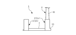
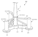
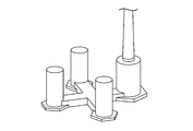
- FIG. 1 and FIG. 2 show an example (first embodiment) of the form of a floating structure according to the embodiment of the present invention.
- a semi-sub floating body structure 1 is formed by connecting lower portions of four columnar columns 2 extending along a vertical direction to each other by a connecting body 3 extending along a horizontal direction.
- the four columns 2 are configured as buoyancy bodies having cavities therein, and are arranged so as to form each vertex of a square in plan view.
- the upper structure 4 is connected to the upper portion of one column (main column) 2a.
- the entire floating structure 1 connected to the upper structure 4 is supported on the water by the four columns 2 expanded in the horizontal direction.
- the main column 2a and the three side columns 2b are cylindrical objects that generate buoyancy by at least partly submerging them in water, and cavities 21 and 22 are formed therein, respectively.
- Each of the cavities 21 and 22 generates buoyancy in each column 2, and at least a part thereof can be used as a ballast tank.
- the cavity 31 is provided also in the inside of the connection body 3, and the connection body 3 can be utilized now as a buoyancy body or a ballast tank which generates a buoyancy as needed.
- a lower hull 23 is provided at the lower part of the main column 2a so as to project horizontally toward the outside in the radial direction.
- the lower hull 23 increases the resistance of water to the vertical movement of the main column 2a, and serves as a heave plate that attenuates shaking.
- the lower hull 23 is a cavity 24 formed integrally with the cavity 21 in the main column 2a.
- a function of adding buoyancy to the main column 2a is also provided.
- the cavity 21 in the main column 2a is wide in the radial direction by the amount of the cavity 24 provided in the lower portion, and the volume is also increased.
- footings 25 functioning as a heave plate for attenuating the shaking of the side columns 2b are formed in the lower part of the three side columns 2b so as to project in the horizontal direction. It does not have a cavity inside and is not configured as a buoyant body.
- a mooring line (not shown) is connected to the lower hull 23 of the main column 2a and the footing 25 of the side column 2b, and the floating structure 1 is moored to the bottom of the water via these mooring lines and stays in a predetermined water area. To do.
- a pump 26 is installed in a cavity 24 below the cavity 21 in the main column 2a, and the space between the pump 26 and the cavity 22 in the side column 2b is within the connecting body 3.
- the water pipes 32 arranged in the cavity 31 communicate with each other.
- the water pumped up from the outside of the floating structure 1 by the pump 26 can be supplied to the cavity 21 of the main column 2a, the cavity 22 of the side column 2b, and the cavity 31 of the connector 3.
- the cavities 21 to 24 in the main column 2a are provided with a machine room (not shown) equipped with various control devices, power supply devices, and the like as necessary.
- the upper structure 4 is, for example, a windmill for wind power generation, and includes a support column 41, a nacelle 42, and a blade 43 as shown in FIG.
- the support column 41 is erected on the main column 2a via a connecting portion 27 provided at the upper end of the main column 2a, and the nacelle 42 includes a generator (not shown) inside to generate electric power by the rotation of the blade 43.
- the upper structure 4 is not limited to the wind power generation facility as illustrated here.
- a solar power generation facility may be used, and as the upper structure 4, various facilities that can be installed on the water, such as various observation facilities, communication facilities, lighting facilities, and mining facilities, are assumed.
- the floating structure 1 and the struts 41 and the blades 43 of the wind turbine 4 as the upper structure are separately manufactured at a factory in the coastal area. After that, they are towed to the sea area where they are installed by ships. In towing, the floating structure 1 has less resistance received from water when there are as few portions as possible to be submerged in water, and can reduce the fuel consumption of the ship. Therefore, the amount of ballast water to be injected into the columns 2 (main column 2a, side column 2b), the lower hull 23, and the cavities 21, 22, 24, 31 inside the coupling body 3 is set to a minimum amount. Tow in the state of the waterline.
- the column 41 of the windmill 4 When arriving at the installation area, the column 41 of the windmill 4 is erected on the connection portion 27 provided on the upper part of the main column 2 a of the floating structure 1, and the blade 43 is attached to the nacelle 42.
- ballast water is appropriately fed from the pump 26 provided in the cavity 24 below the cavity 21 in the main column 2 a to the cavities 22 and 31 in the side column 2 b and the connecting body 3 through the water feeding pipe 32.
- 31 is used as an adjustment ballast tank to adjust the balance of the floating structure 1 and stabilize it in water.
- water is also poured into the cavities 21 and 24 in the main column 2a or the lower hull 23 as necessary.
- the floating structure 1 is installed horizontally with the wind turbine 4 supported on the upper portion as shown in FIGS. At this time, the draft is located near the middle of each column 2 in the vertical direction.
- each column 2 a significantly larger weight is added to the main column 2a to which the wind turbine 4 is connected at the upper part as compared with the other side columns 2b.
- the lower hull 23 is installed at the lower portion, so that the volume of the submerged portion is larger than that of the side column 2b, and the resulting buoyancy is also large.
- the weight applied to the main column 2a from the upper structure 4 is counteracted, and the imbalance of the load distribution with the side column 2b is corrected, so that the balance of the entire floating structure 1 is maintained.
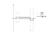
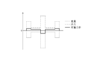
- FIG. 3A is a schematic view of the floating structure 1 as seen in a cross section passing through the main column 2a and a side column 2b diagonally positioned therewith, and FIG. 3B shows the distribution of weight and buoyancy in this cross section. .
- 3B shows the weight (downward load) applied to each part shown in FIG. 3A.
- the main column 2a located on the right side since the wind turbine 4 is connected to the upper part, a large weight is added as compared with the left side column 2b.
- 3B indicates the buoyancy (upward load) applied to each part of the floating structure 1, and the main column 2a having the lower hull 23 has a larger buoyancy than the side column 2b. Yes.
- the solid line in FIG. 3B shows the load as the sum of the weight and buoyancy. A slight downward load is applied to the main column 2a and a slight upward load is applied to the side column 2b, and the total value of the floating structure 1 is zero and balances.
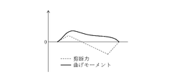
- FIG. 3C shows the distribution of the shearing force and the bending moment generated in various places of the floating structure 1 due to the load distribution as described above.
- the shearing force (vertical force) indicated by the broken line in FIG. 3C is expressed as an integral of the load curve indicated by the solid line in FIG. 3B, and the bending moment indicated by the solid line in FIG. 3C is the integral of the shearing force. appear.
- the bending moment shows the distribution that becomes the largest at the position on the left side of the connector 3.
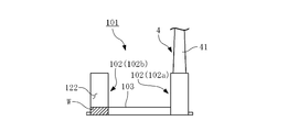
- FIGS. 4A to 4C the distribution of weight and the like in a conventional general floating structure is shown in FIGS. 4A to 4C.
- the main column 102a is not provided with an additional buoyancy body such as the lower hull 23 (see FIG. 3A), and the main column 102a and the side column 102b.
- the buoyancy applied to each column 102 (main column 102a and side column 102b) is the same.
- the floating structure 101 having such a configuration in order to maintain a balance between the main column 102a and the side column 102b, it is common to inject the ballast water W into the cavity 122 in the side column 102b.
- the weight (downward load) indicated by the broken line is more ballast than the side column 2b of the first embodiment in the left side column 102b. It becomes larger by the amount of water W (see FIG. 3B). Further, the buoyancy (upward load) indicated by the alternate long and short dash line is equal between the main column 102a and the side column 102b.
- the volume for the adjustment ballast tank is not required, so that the entire side column 2b can be reduced, which also contributes to the weight reduction of the steel material (the main column, though) 2a requires as much steel as the lower hull 23, but less than the reduction in the side column 2b).
- the floating structure 1 of the first embodiment can reduce the amount of drainage by about 2%, for example, compared with the floating structure 101 of the first reference example.
- a machine room containing the pump 26 and other devices is installed at the lower part of the cavity 21 in the main column 2a.
- the equipment related to the upper structure 4 for example, when the upper structure 4 is a windmill as shown in FIG. 1), the equipment related to power conversion and transmission, the control device for the windmill 4, etc.
- Installation near the body 4 is the most efficient in terms of wiring and piping, and it is easier to arrange other devices (pump 26 and its control device, etc.) in the same place as much as possible.
- the lower hull 23 is provided at the lower part of the main column 2a, and the cavity 21 is widened by the amount of the cavity 24. Therefore, in installing various devices as described above, There is also an advantage of easy layout.
- a plurality of columns 2 configured as columnar buoyancy bodies extending along the vertical direction and a connection for connecting the plurality of columns 2 in a state of being expanded in the horizontal direction.
- a floating structure 1 including a body 3 and configured to connect an upper structure (wind turbine) 4 to an upper portion of at least a part (main column 2a) of the column 2 and to support the whole on the water.
- the column 2 (main column 2a) to which a larger load applied to the other column 2 from the upper structure 4 is applied downward is configured such that the buoyancy generated in the main column 2a is larger than that of the other column 2 (side column 2b). Therefore, by applying buoyancy to the main column 2a so as to counter the load from the upper structure 4, the imbalance of the load distribution between the columns 2 is corrected, and the connected body Resulting bending moment can be reduced.
- the volume of the submerged portion of the main column 2a is larger than that of the other columns 2 (side columns 2b), so that the buoyancy against the load from the upper structure 4 is main. It can be appropriately given to the column 2a.
- the main column 2a is provided by the lower hull 23.
- the resistance of water to the vertical movement of the water can be increased, and the shaking can be attenuated.
- the devices related to the operation of the upper structure 4 or the floating structure 1 are arranged inside the main column 2a, various devices as described above are arranged here. A wide space for installation and easy layout.
- the first embodiment it is possible to avoid the increase in size and strength of the structure as much as possible, and to correct the load balance while suppressing the cost of construction.
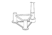
- FIG. 5 shows another example (second embodiment) of the form of the floating structure according to the embodiment of the present invention.
- the basic configuration is the same as that of the floating structure 1 of the first embodiment described above (see FIGS. 1 and 2).
- the arrangement of the columns is the first. This is different from the embodiment.
- the floating structure 201 of the second embodiment three side columns 202b among the four columns 202 are arranged so as to form vertices of an equilateral triangle in plan view, and the main column 202a is the side column 202b. It is located at the center of the triangle.
- the central main column 202a and the peripheral side columns 202b are connected by a connecting body 203, and the wind turbine 4 as an upper structure is connected to the upper part of the main column 202a. That is, the arrangement is common to the floating structure described in Patent Document 2.
- a lower hull 223 as a heave plate and a buoyant body is provided below the main column 202a.
- a footing 225 as a heave plate is provided at the lower part of the side column 202b, and a larger buoyancy is generated in the main column 202a than in the side column 202b by the amount of the lower hull 223. .
- the structure of the connecting body 203 that connects the columns 202 to each other is more complicated than that of the connecting body 3 of the first embodiment described above (see FIGS. 1 and 2).
- the mechanical imbalance between the columns is corrected. This will be described below.
- the upper structure 4 is connected to the main column 202a. Therefore, as shown by a broken line in FIG.
- the central main column 202a is significantly larger than the left and right side columns 202b.
- the buoyancy (upward load) applied to the central main column 202a is applied to the left and right side as shown by the one-dot chain line in FIG. 6B. It is larger than the column 202b.
- the load as the sum of the weight and the buoyancy is slightly downward in the main column 202a and slightly upward in the side column 202b.
- FIG. 7A shows an example (second reference example) of a floating structure as a reference example of the second embodiment.
- the floating structure 301 of the second reference example has the same configuration as the floating structure described in Patent Document 2, and the main column is located at the center of the three side columns 302b that form the vertices of an equilateral triangle in plan view.
- the arrangement in which the main column 302a and the side column 302b are connected by the connecting body 303 is the same as that of the second embodiment (see FIGS. 5 and 6A).
- the second reference example is different from the second embodiment in that the main column 302a is not provided with a lower hull and the side column 302b is provided with a lower hull 323.
- the downward load distribution is substantially the same as in the second embodiment (see FIG. 6B.
- the main column 302a does not have a lower hull.
- the load is slightly smaller by the amount, and conversely the side column 302b is larger by the lower hull 323).
- the buoyancy indicated by the alternate long and short dash line is small in the main column 302a and large in the side column 302b.
- the total load is large downward in the central main column 302a and large upward in the left and right side columns 302b, as indicated by the solid line.
- the ballast for balancing the weight of the upper structure 4 Although it is not necessary to inject water into the side column 302b, there is still a load imbalance between the main column 302a to which a large load is applied from the upper structure 4 and the side column 302b. A large shearing force or bending moment is generated in the body 303.
- the lower hull 223 is installed on the main column 202a to which the upper structure 4 is connected to increase the buoyancy and counter the weight of the upper structure 4. This reduces the load imbalance with the side column 202b.
- the required strength of the connection body 203 can be reduced, and the amount of steel material required for the connection body 203 can be reduced.
- the lower main hull 223 is required for the central main column 202a, it is unnecessary to install the lower hull in the side column 202b located in the periphery, or it may be small. Therefore, the amount of steel material applied to the entire floating structure 201 can be reduced.
- the second embodiment also avoids the increase in size and strength of the structure as much as possible. The load balance can be corrected while reducing the construction cost.
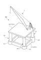
- FIG. 8 shows still another example (third embodiment) of the form of the floating structure according to the embodiment of the present invention.
- the upper structure 5 connected to the upper part of the column 402 constituting the floating structure 401 is not a windmill but a crane. This is different from the embodiment (see FIGS. 1 and 2) and the second embodiment (see FIG. 5).
- the upper portions of the four columns 402 are connected to each other by an upper connecting body 403a and the lower portions are connected to each other by a lower connecting body 403b.
- the upper connecting body 403a forms a substantially square horizontal surface in plan view at the upper ends of the four columns 402, and the four columns 402 are arranged at the positions of the respective vertices of the square formed by the upper connecting body 403a.
- the lower connecting body 403b connects the lower ends of the columns 402 so as to form a square side.
- the upper structure 5 which is a crane is installed on the surface which the upper coupling body 403a makes.
- one of the columns 402 is not positioned directly below the center of gravity of the crane 5 that is the upper structure, and the downward load due to the weight of the crane 5 is four through the upper coupling body 403a. Will be added to each column 402 of the book.
- the position of the center of gravity of the crane 5 does not coincide with the center of gravity of the entire four columns 402 in plan view, and is in an eccentric state. Therefore, the load applied from the crane 5 to the four columns 402 is not uniform, and there is a bias between the columns 402. In the state shown in FIG.
- the center of gravity of the crane 5 is eccentric to the right in the figure with respect to the center of gravity of the four columns 402, and a particularly large downward load is applied to the column 402 located at the right end.
- the lower hull 423 provided in the right column 402 in the drawing is made larger than the lower hull 423 in the other column 402, and a large buoyancy is exerted on the right column 402 in the drawing. As a result, the load is balanced between the columns 402.
- the third embodiment also avoids the increase in structure size and strength as much as possible. The load balance can be corrected while reducing the construction cost.
- FIG. 9 shows still another example (fourth embodiment) of the form of the floating structure according to the embodiment of the present invention.
- the basic configuration is the same as that of the first embodiment (see FIGS. 1 and 2).
- a buoyancy body 533 is provided at a position corresponding to a connecting portion with the main column 502a, and the buoyancy is generated by the buoyancy body 533 in the main column 502a connected to the upper structure 4 at the top.
- the buoyancy when the buoyancy is applied to the main column 502a, it is not necessary to change the structure of the main column 502a itself, and the design of the coupling body 503 may be changed. Since various devices are installed in the main column 502a, the internal structure and layout may not be very flexible, but the connection body 503 has relatively few restrictions on the design for providing the buoyancy body 533. There is an advantage.
- the column 502 (main column 502a) in which a larger load applied from the upper structure 4 to the other columns 502 is applied downward among the coupling bodies 503 that connect the columns 502 to each other. Since the buoyancy body 533 is provided in the connecting portion, the buoyancy can be imparted to the main column 502a without changing the structure of the main column 502a.
- the fourth embodiment described above also avoids an increase in structure size and strength as much as possible. The load balance can be corrected while reducing the construction cost.
- 10A and 10B show other examples of the form of the floating structure according to the implementation of the present invention.
- the number of columns can be three, or five or more, although not shown.
- the arrangement of the columns and the structure of the connecting body can be changed as appropriate in accordance with the type and structure of the upper structure and other conditions.
- 10B except that the main column is provided with a lower hull as in the first embodiment (see FIGS. 1 and 2) and the connecting body is provided with a buoyant body as in the fourth embodiment (see FIG. 9). Large buoyancy can be imparted by changing the diameter of the column itself as shown.
- the floating structure of the present invention can take various configurations.
- Each of these embodiments can avoid the increase in size and strength of the structure as much as possible, and can correct the load balance while reducing the cost of construction.
Landscapes
- Engineering & Computer Science (AREA)
- Combustion & Propulsion (AREA)
- Mechanical Engineering (AREA)
- Chemical & Material Sciences (AREA)
- Ocean & Marine Engineering (AREA)
- Fluid Mechanics (AREA)
- Physics & Mathematics (AREA)
- Architecture (AREA)
- Civil Engineering (AREA)
- Structural Engineering (AREA)
- Sustainable Energy (AREA)
- General Engineering & Computer Science (AREA)
- Life Sciences & Earth Sciences (AREA)
- Sustainable Development (AREA)
- Wind Motors (AREA)
Abstract
Description
2 コラム
2a コラム(メインコラム)
2b コラム(サイドコラム)
3 連結体
4 上部構造体(風車)
5 上部構造体(クレーン)
23 ロワーハル
201 浮体構造物
202 コラム
202a コラム(メインコラム)
202b コラム(サイドコラム)
203 連結体
223 ロワーハル
401 浮体構造物
402 コラム
403 連結体
403a 連結体(上部連結体)
403b 連結体(下部連結体)
423 ロワーハル
501 浮体構造物
502 コラム
502a コラム(メインコラム)
502b コラム(サイドコラム)
503 連結体
533 浮力体
Claims (5)
- 垂直方向に沿って延びる柱状の浮力体として構成された複数のコラムと、該複数のコラムを水平方向に展開した状態で連結する連結体を備え、前記コラムのうち少なくとも一部の上部に上部構造体を接続し、全体を水上に支持するよう構成した浮体構造物であって、
前記コラムのうち、前記上部構造体から他のコラムに加わるより大きい荷重が下向きに加わるコラムに関し、該コラムに生じる浮力が他のコラムより大きくなるよう構成した浮体構造物。 - 前記上部構造体から他のコラムに加わるより大きい荷重が下向きに加わるコラムの没水部の体積を他のコラムより大きく構成した、請求項1に記載の浮体構造物。
- 前記上部構造体から他のコラムに加わるより大きい荷重が下向きに加わるコラムの下部に、該コラムから水平方向に張り出すよう、内部に空洞を有するロワーハルを備えた、請求項2に記載の浮体構造物。
- 前記上部構造体から他のコラムに加わるより大きい荷重が下向きに加わるコラムの内部に、前記上部構造体又は前記浮体構造物の運転に関連する機器類を配置した、請求項2又は3に記載の浮体構造物。
- 前記コラム同士を連結する連結体のうち、前記上部構造体から他のコラムに加わるより大きい荷重が下向きに加わるコラムとの連結部に浮力体を備えた、請求項1に記載の浮体構造物。
Priority Applications (8)
| Application Number | Priority Date | Filing Date | Title |
|---|---|---|---|
| PCT/JP2016/084973 WO2018096650A1 (ja) | 2016-11-25 | 2016-11-25 | 浮体構造物 |
| KR1020197015865A KR102257418B1 (ko) | 2016-11-25 | 2016-11-25 | 부체 구조물 |
| JP2018552350A JP6718518B2 (ja) | 2016-11-25 | 2016-11-25 | 浮体構造物 |
| PT169224276T PT3546337T (pt) | 2016-11-25 | 2016-11-25 | Estrutura flutuante |
| CN201680091124.2A CN109982923A (zh) | 2016-11-25 | 2016-11-25 | 浮体结构物 |
| EP16922427.6A EP3546337B1 (en) | 2016-11-25 | 2016-11-25 | Floating structure |
| ES16922427T ES2989365T3 (es) | 2016-11-25 | 2016-11-25 | Estructura flotante |
| CN202511652675.9A CN121224928A (zh) | 2016-11-25 | 2016-11-25 | 浮体结构物 |
Applications Claiming Priority (1)
| Application Number | Priority Date | Filing Date | Title |
|---|---|---|---|
| PCT/JP2016/084973 WO2018096650A1 (ja) | 2016-11-25 | 2016-11-25 | 浮体構造物 |
Publications (1)
| Publication Number | Publication Date |
|---|---|
| WO2018096650A1 true WO2018096650A1 (ja) | 2018-05-31 |
Family
ID=62195078
Family Applications (1)
| Application Number | Title | Priority Date | Filing Date |
|---|---|---|---|
| PCT/JP2016/084973 Ceased WO2018096650A1 (ja) | 2016-11-25 | 2016-11-25 | 浮体構造物 |
Country Status (7)
| Country | Link |
|---|---|
| EP (1) | EP3546337B1 (ja) |
| JP (1) | JP6718518B2 (ja) |
| KR (1) | KR102257418B1 (ja) |
| CN (2) | CN109982923A (ja) |
| ES (1) | ES2989365T3 (ja) |
| PT (1) | PT3546337T (ja) |
| WO (1) | WO2018096650A1 (ja) |
Cited By (7)
| Publication number | Priority date | Publication date | Assignee | Title |
|---|---|---|---|---|
| FR3090567A1 (fr) * | 2018-12-24 | 2020-06-26 | Doris Engineering | Plateforme navale de support d’une éolienne et installation navale associée |
| WO2020203435A1 (ja) * | 2019-03-29 | 2020-10-08 | ジャパンマリンユナイテッド株式会社 | 浮体構造物、浮体式風力発電装置及び浮体構造物の製造方法 |
| WO2020244476A1 (zh) * | 2019-06-04 | 2020-12-10 | 上海交通大学 | 低重心桁架半潜型浮式风力机 |
| FR3108953A1 (fr) | 2020-04-06 | 2021-10-08 | Olivier JUIN | Structure porteuse d’installation de modules de captage d’energie eolienne |
| JP2022183904A (ja) * | 2021-05-31 | 2022-12-13 | 大成建設株式会社 | 水上風力発電施設組立方法および浮体構造物 |
| JP2024544295A (ja) * | 2021-12-22 | 2024-11-28 | ポスコ カンパニー リミテッド | 浮遊式構造体および風力発電装置 |
| US12157545B2 (en) | 2019-02-12 | 2024-12-03 | Principle Power Inc. | Wind energy power plant and method of construction |
Families Citing this family (7)
| Publication number | Priority date | Publication date | Assignee | Title |
|---|---|---|---|---|
| KR102093240B1 (ko) | 2019-08-19 | 2020-03-25 | 박승균 | 다중 칼럼으로 구성된 자기 선회식 해상풍력 부선 |
| SE544127C2 (en) * | 2020-04-30 | 2022-01-04 | Bassoe Tech Ab | Floating semi-submersible wind energy platform with t-shaped pontoon and its assembly |
| CN120621595A (zh) * | 2020-10-30 | 2025-09-12 | 现代重工业株式会社 | 漂浮式海洋结构物及具有其的漂浮式海洋发电装置 |
| KR102624041B1 (ko) * | 2020-10-30 | 2024-01-12 | 에이치디현대중공업 주식회사 | 부유식 해양 구조물 및 이를 구비하는 부유식 해양 발전 장치 |
| FR3117553B1 (fr) | 2020-12-10 | 2022-11-04 | Bourbon Offshore Gaia | Procédé d’assemblage d’un parc éolien offshore flottant |
| CN114148462A (zh) * | 2021-08-04 | 2022-03-08 | 中国华能集团清洁能源技术研究院有限公司 | 基于单点系泊的半潜浮式平台和偏心式风机系统 |
| KR20250009766A (ko) * | 2023-07-11 | 2025-01-20 | 주식회사 포스코 | 부유식 해상 발전장치 |
Citations (6)
| Publication number | Priority date | Publication date | Assignee | Title |
|---|---|---|---|---|
| JP2001180584A (ja) * | 1999-12-21 | 2001-07-03 | Sumitomo Heavy Ind Ltd | セミサブ型浮体構造物 |
| JP2008074297A (ja) * | 2006-09-22 | 2008-04-03 | Mitsubishi Heavy Ind Ltd | 浮体構造物 |
| JP2010280301A (ja) | 2009-06-04 | 2010-12-16 | Shimizu Corp | 洋上施設用浮体構造物および洋上施設の施工方法 |
| JP2015016860A (ja) | 2008-04-23 | 2015-01-29 | プリンシプル・パワー・インコーポレーテツド | 洋上風力タービンの支持のための水エントラップメントプレートおよび非対称的係留システムを伴う、コラムで安定化された洋上プラットホーム |
| EP2933181A1 (en) * | 2013-01-21 | 2015-10-21 | MHI Vestas Offshore Wind A/S | Method for maintaining floating wind-power generation device |
| GB2538329A (en) * | 2015-05-05 | 2016-11-16 | Oceanflow Dev Ltd | Platform and assembly solution for a floating offshore device |
Family Cites Families (3)
| Publication number | Priority date | Publication date | Assignee | Title |
|---|---|---|---|---|
| US20120103244A1 (en) * | 2010-10-28 | 2012-05-03 | Jin Wang | Truss Cable Semi-submersible Floater for Offshore Wind Turbines and Construction Methods |
| FR2967642B1 (fr) * | 2010-11-22 | 2013-08-16 | Nass&Wind Ind | Dispositif d'eolienne offshore avec flotteur semi-submersible particulier |
| WO2013040871A1 (zh) * | 2011-09-22 | 2013-03-28 | Huang Canguang | 支撑海上风机和海洋能发电机的预应力混凝土浮式平台 |
-
2016
- 2016-11-25 PT PT169224276T patent/PT3546337T/pt unknown
- 2016-11-25 CN CN201680091124.2A patent/CN109982923A/zh active Pending
- 2016-11-25 WO PCT/JP2016/084973 patent/WO2018096650A1/ja not_active Ceased
- 2016-11-25 CN CN202511652675.9A patent/CN121224928A/zh active Pending
- 2016-11-25 ES ES16922427T patent/ES2989365T3/es active Active
- 2016-11-25 JP JP2018552350A patent/JP6718518B2/ja active Active
- 2016-11-25 KR KR1020197015865A patent/KR102257418B1/ko active Active
- 2016-11-25 EP EP16922427.6A patent/EP3546337B1/en active Active
Patent Citations (7)
| Publication number | Priority date | Publication date | Assignee | Title |
|---|---|---|---|---|
| JP2001180584A (ja) * | 1999-12-21 | 2001-07-03 | Sumitomo Heavy Ind Ltd | セミサブ型浮体構造物 |
| JP2008074297A (ja) * | 2006-09-22 | 2008-04-03 | Mitsubishi Heavy Ind Ltd | 浮体構造物 |
| JP2015016860A (ja) | 2008-04-23 | 2015-01-29 | プリンシプル・パワー・インコーポレーテツド | 洋上風力タービンの支持のための水エントラップメントプレートおよび非対称的係留システムを伴う、コラムで安定化された洋上プラットホーム |
| JP2015037935A (ja) * | 2008-04-23 | 2015-02-26 | プリンシプル・パワー・インコーポレーテツド | 洋上風力タービンの支持のための水エントラップメントプレートおよび非対称的係留システムを伴う、コラムで安定化された洋上プラットホーム |
| JP2010280301A (ja) | 2009-06-04 | 2010-12-16 | Shimizu Corp | 洋上施設用浮体構造物および洋上施設の施工方法 |
| EP2933181A1 (en) * | 2013-01-21 | 2015-10-21 | MHI Vestas Offshore Wind A/S | Method for maintaining floating wind-power generation device |
| GB2538329A (en) * | 2015-05-05 | 2016-11-16 | Oceanflow Dev Ltd | Platform and assembly solution for a floating offshore device |
Non-Patent Citations (1)
| Title |
|---|
| See also references of EP3546337A4 |
Cited By (14)
| Publication number | Priority date | Publication date | Assignee | Title |
|---|---|---|---|---|
| US11053924B2 (en) | 2018-12-24 | 2021-07-06 | Doris Engineering | Offshore wind turbine floating support and associated installation means |
| EP3674198A1 (fr) * | 2018-12-24 | 2020-07-01 | Doris Engineering | Plateforme navale de support d'une éolienne et installation navale associée |
| FR3090567A1 (fr) * | 2018-12-24 | 2020-06-26 | Doris Engineering | Plateforme navale de support d’une éolienne et installation navale associée |
| US12157545B2 (en) | 2019-02-12 | 2024-12-03 | Principle Power Inc. | Wind energy power plant and method of construction |
| JP7234005B2 (ja) | 2019-03-29 | 2023-03-07 | ジャパンマリンユナイテッド株式会社 | 浮体構造物、浮体式風力発電装置及び浮体構造物の製造方法 |
| JP2020163979A (ja) * | 2019-03-29 | 2020-10-08 | ジャパンマリンユナイテッド株式会社 | 浮体構造物、浮体式風力発電装置及び浮体構造物の製造方法 |
| WO2020203435A1 (ja) * | 2019-03-29 | 2020-10-08 | ジャパンマリンユナイテッド株式会社 | 浮体構造物、浮体式風力発電装置及び浮体構造物の製造方法 |
| WO2020244476A1 (zh) * | 2019-06-04 | 2020-12-10 | 上海交通大学 | 低重心桁架半潜型浮式风力机 |
| US12104572B2 (en) | 2019-06-04 | 2024-10-01 | Shanghai Jiao Tong University | Semi-submersible floating wind power generator |
| FR3108953A1 (fr) | 2020-04-06 | 2021-10-08 | Olivier JUIN | Structure porteuse d’installation de modules de captage d’energie eolienne |
| WO2021205293A1 (fr) | 2020-04-06 | 2021-10-14 | Juin Olivier | Structure porteuse d'installation de modules de captage d'energie eolienne |
| JP2022183904A (ja) * | 2021-05-31 | 2022-12-13 | 大成建設株式会社 | 水上風力発電施設組立方法および浮体構造物 |
| JP7473503B2 (ja) | 2021-05-31 | 2024-04-23 | 大成建設株式会社 | 水上風力発電施設組立方法 |
| JP2024544295A (ja) * | 2021-12-22 | 2024-11-28 | ポスコ カンパニー リミテッド | 浮遊式構造体および風力発電装置 |
Also Published As
| Publication number | Publication date |
|---|---|
| PT3546337T (pt) | 2024-10-18 |
| JPWO2018096650A1 (ja) | 2019-07-04 |
| EP3546337A4 (en) | 2020-07-08 |
| ES2989365T3 (es) | 2024-11-26 |
| CN109982923A (zh) | 2019-07-05 |
| EP3546337B1 (en) | 2024-09-25 |
| EP3546337A1 (en) | 2019-10-02 |
| CN121224928A (zh) | 2025-12-30 |
| KR102257418B1 (ko) | 2021-05-31 |
| KR20190072641A (ko) | 2019-06-25 |
| JP6718518B2 (ja) | 2020-07-08 |
Similar Documents
| Publication | Publication Date | Title |
|---|---|---|
| WO2018096650A1 (ja) | 浮体構造物 | |
| KR102294285B1 (ko) | 파력 및 풍력 부하를 최적으로 전달하는 부유식 풍력 터빈 플랫폼 구조물 | |
| CN110461702B (zh) | 浮动海上平台 | |
| KR101713618B1 (ko) | 해안 풍력 터빈의 지지를 위한 워터-엔트랩먼트 플레이트 및 비대칭 무링 시스템을 가진 칼럼-안정화된 해안 플랫폼 | |
| JP6244013B2 (ja) | オフショア設備における、タービンタワーおよびサブステーションまたは類似の要素のための潜水可能なアクティブ支持構造 | |
| CN103818523B (zh) | 外飘式张力腿浮动风机基础、海上风力发电机及施工方法 | |
| KR20130122801A (ko) | 스파형 부체 구조물 | |
| HK1251207A1 (en) | Floating wind turbine platform structure with optimized transfer of wave and wind loads | |
| US20230407844A1 (en) | Wind turbine offshore support structure | |
| KR20250065782A (ko) | 부유식 해양 구조물 및 이를 구비하는 부유식 해양 발전 장치 | |
| US20240309852A1 (en) | Semi-submersible floating platform for offshore wind turbine | |
| KR20140120154A (ko) | 부유식 해상 풍력 발전기의 트러스형 하부 구조물 | |
| KR102523952B1 (ko) | 타워일체형 해상풍력 부유체 및 그 제조방법 | |
| JP7817341B2 (ja) | 浮遊式海洋構造物及びそれを備える浮遊式海洋発電装置 | |
| KR20250093872A (ko) | 단일점 계류 구조물 및 이를 갖는 부유식 풍력발전기 | |
| KR20140058060A (ko) | 해상 부유식 풍력발전장치 |
Legal Events
| Date | Code | Title | Description |
|---|---|---|---|
| 121 | Ep: the epo has been informed by wipo that ep was designated in this application |
Ref document number: 16922427 Country of ref document: EP Kind code of ref document: A1 |
|
| ENP | Entry into the national phase |
Ref document number: 2018552350 Country of ref document: JP Kind code of ref document: A |
|
| NENP | Non-entry into the national phase |
Ref country code: DE |
|
| ENP | Entry into the national phase |
Ref document number: 20197015865 Country of ref document: KR Kind code of ref document: A |
|
| ENP | Entry into the national phase |
Ref document number: 2016922427 Country of ref document: EP Effective date: 20190625 |