WO2018096657A1 - Climatiseur - Google Patents
Climatiseur Download PDFInfo
- Publication number
- WO2018096657A1 WO2018096657A1 PCT/JP2016/085013 JP2016085013W WO2018096657A1 WO 2018096657 A1 WO2018096657 A1 WO 2018096657A1 JP 2016085013 W JP2016085013 W JP 2016085013W WO 2018096657 A1 WO2018096657 A1 WO 2018096657A1
- Authority
- WO
- WIPO (PCT)
- Prior art keywords
- stop cock
- outlet
- air conditioner
- drain
- lid
- Prior art date
- Legal status (The legal status is an assumption and is not a legal conclusion. Google has not performed a legal analysis and makes no representation as to the accuracy of the status listed.)
- Ceased
Links
Images


Classifications
-
- F—MECHANICAL ENGINEERING; LIGHTING; HEATING; WEAPONS; BLASTING
- F24—HEATING; RANGES; VENTILATING
- F24F—AIR-CONDITIONING; AIR-HUMIDIFICATION; VENTILATION; USE OF AIR CURRENTS FOR SCREENING
- F24F13/00—Details common to, or for air-conditioning, air-humidification, ventilation or use of air currents for screening
- F24F13/22—Means for preventing condensation or evacuating condensate
Definitions
- the present invention relates to an air conditioner provided with a drain port for draining drain water.
- Patent Document 1 describes a water receiver for a dehumidifier.
- This dehumidifier water receiver has a drain hole and a bolt-shaped plug attached to the drain hole. An internal thread is formed inside the drainage hole.
- the plug is formed with a male screw that is screwed with the female screw.
- the bolt-shaped stopper may shrink due to aging or heat.
- the stopper contracts, a gap is generated between the drain hole and the stopper, which causes a problem that water leakage may occur in the container.
- the present invention has been made to solve the above-described problems, and an object of the present invention is to provide an air conditioner that can prevent water leakage even when the stop cock contracts.
- An air conditioner includes a drain pan that receives drain water from a heat exchanger, an inlet portion that opens to the inside of the drain pan, an outlet portion that opens to the outside of the drain pan, and the inlet portion and the outlet portion.
- a drainage port portion for draining drain water in the drain pan from the outlet portion side to the drainage port portion.
- a water stop cock that is detachably inserted and is in close contact with the inner peripheral surface, a lid that is detachably attached to the outlet portion, and is disposed between the water stop cock and the lid, and the water stop cock is And an urging member that urges toward the inlet side.
- the stop cock can be brought into close contact with the inner peripheral surface of the drain port portion by the urging force of the urging member, water leakage can be prevented even if the stop cock contracts.
- FIG. 1 is a partial cross-sectional view showing a schematic configuration of the air conditioner according to the present embodiment.
- the indoor unit 100 includes a housing 101 whose bottom surface is open, and a decorative panel 102 attached from the bottom surface opening of the housing 101 to the periphery of the ceiling opening.
- a fan motor 103 is attached to the top plate of the housing 101.
- a turbo fan 104 is fixed to the output shaft of the fan motor 103.
- a heat exchanger 105 is disposed around the turbo fan 104 so as to surround the turbo fan 104.
- a drain pan 106 that receives the condensed water from the heat exchanger 105 as drain water is provided below the heat exchanger 105.
- a drain port 10 is provided at the bottom of the water storage section of the drain pan 106.
- the drain port 10 and the drain pan 106 are separate members, but the drain port 10 may be a part of the drain pan 106.
- a water stop cock 20 is detachably attached to the drain port 10. In a state where the stop cock 20 is attached to the drain port 10, drain water from the heat exchanger 105 is stored in the drain pan 106. When the stop cock 20 is removed from the drain port 10, the drain water stored in the drain pan 106 is drained to the outside.
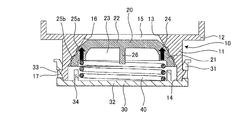
- FIG. 2 is a cross-sectional view showing a configuration in the vicinity of the drain port 10 in the air conditioner according to the present embodiment.
- the drain port 10 includes a cylindrical tubular portion 11 (an example of a first tubular portion) and a flange portion 12 formed in a collar shape at the upper end of the tubular portion 11. Have.
- the drain port 10 is attached to the drain pan 106 by fitting the tubular portion 11 into the opening formed in the bottom of the drain pan 106 (not shown in FIG. 2) from above.
- a drain port 15 is formed through the inside of the tubular portion 11.
- an inlet portion 13 that opens to the inside of the drain pan 106 and serves as an inlet of the drain port 15 is formed.
- an outlet portion 14 that opens to the outside of the drain pan 106 and serves as an outlet of the drain port 15 is formed.
- At least a part of the drain port 15 in the axial direction is defined by the inner peripheral surface 16 of the cylindrical portion 11.
- the inner peripheral surface 16 is formed in a tapered shape (that is, a conical surface shape) having a smaller diameter as it is closer to the inlet portion 13 and a larger diameter as it is closer to the outlet portion 14.
- two locking claws 17 for attaching a lid 30 to be described later are formed on the outer peripheral surface of the cylindrical portion 11.
- the water stopper 20 is made of an elastic body such as rubber.
- the stop cock 20 is detachably inserted into the drain port 15 formed in the drain port unit 10 from the outlet unit 14 side, and is in close contact with the inner peripheral surface 16.
- the water stop cock 20 always receives an urging force in a direction in close contact with the inner peripheral surface 16 by a coil spring 40 described later.
- the urging force received by the water stop cock 20 is represented by a thick arrow.
- the water faucet 20 has a cylindrical part 21 (an example of a second cylindrical part), a bottom part 22 and a hollow part 23.
- the cylindrical portion 21 has a conical surface shape in which the diameter is smaller as it is closer to the upper end and the diameter is larger as it is closer to the lower end.
- the cylindrical portion 21 includes a tapered outer peripheral surface 24 that faces the inner peripheral surface 16 of the drain port 10.
- the bottom portion 22 is formed at the upper end of the cylindrical portion 21 that becomes the inlet portion 13 side of the drain port portion 10.
- the hollow part 23 is formed inside the cylindrical part 21. The upper end of the hollow portion 23 is closed by the bottom portion 22, and the lower end of the hollow portion 23 on the outlet portion 14 side of the drain port portion 10 is opened.
- annular convex portions 25 a and 25 b that are in close contact with the entire periphery of the inner peripheral surface 16 are formed.
- the convex portions 25 a and 25 b are crushed by being in close contact with the inner peripheral surface 16 and deformed following the inner peripheral surface 16. Thereby, the water stop of the water stop cock 20 is raised.
- a rib-like handle portion 26 that protrudes toward the hollow portion 23 is formed on the bottom portion 22. The handle portion 26 is used, for example, when the stop cock 20 is removed from the drain port portion 10.
- a lid 30 and a coil spring 40 are detachably attached to the outlet 14 side of the drain port 10.
- FIG. 3 is a perspective view showing an assembled state of the lid 30 and the coil spring 40 in the air conditioner according to the present embodiment.
- the lid 30 has a cylindrical shape with one end closed. That is, the lid 30 has a cylindrical tubular portion 31 and a bottom portion 32 that closes the lower end of the tubular portion 31.
- the lower end of the tubular portion 11 of the drain port portion 10 (that is, the end portion on the outlet portion 14 side of the tubular portion 11) is fitted inside the tubular portion 31.
- the cylindrical portion 31 is formed with two locking holes 33 that are locked by the two locking claws 17 of the drain port 10.
- a pair of arc-shaped positioning ribs 34 and a pair of hook-shaped hook portions 35 are formed on the surface of the bottom portion 32 on the cylindrical portion 31 side.
- the positioning rib 34 is provided for positioning the coil spring 40.
- the hook portion 35 is provided for hooking and attaching the coil spring 40.
- the lid 30 and the coil spring 40 are assembled together by attaching the coil spring 40 to the hook portion 35.
- the coil spring 40 is disposed between the stop cock 20 and the lid 30 in a compressed state.
- the upper end portion of the coil spring 40 is in contact with the water stop cock 20, and the lower end portion of the coil spring 40 is attached to the lid 30. That is, the reaction force of the coil spring 40 acts on both the water stop cock 20 and the lid 30.
- the lid 30 is fixed to the drain port 10 by the locking claw 17 locking the locking hole 33. Accordingly, the coil spring 40 biases the water stop cock 20 toward the inlet portion 13 of the drain port portion 10. Due to the biasing force of the coil spring 40, the stop cock 20 is brought into close contact with the inner peripheral surface 16 of the drain port 10.
- the stop cock 20 is inserted into the drain port 10 from the outlet 14 side.
- the lid 30 and the coil spring 40 assembled in advance are attached to the drain port 10, and the locking claw 17 is locked in the locking hole 33.
- the lid 30 is fixed to the drain port 10, and the stop cock 20 is brought into close contact with the inner peripheral surface 16 of the drain port 10 by the biasing force of the coil spring 40.
- FIG. 4 is a diagram for explaining the effect of the air conditioner according to the present embodiment.
- the inclination angle of the inner peripheral surface 16 of the drain port 10 is ⁇ .
- the radius of the water stopper 20 is contracted by the contraction width ⁇ due to aging or heat.
- the external shape of the water stop cock 20 before contraction is shown with the dashed-two dotted line.
- the stop cock 20 contracts, a gap may be formed between the stop cock 20 and the inner peripheral surface 16 of the drain port 10.
- the stop cock 20 is biased by the coil spring 40, the contracted stop cock 20 moves to the inlet 13 side by the biasing force of the coil spring 40 as shown in FIG.
- the travel distance of the water stop cock 20 is represented by ( ⁇ / tan ⁇ ) when the inclination angle ⁇ of the inner peripheral surface 16 and the contraction width ⁇ of the water stop cock 20 are used. According to the present embodiment, even if the stop cock 20 contracts, the stop cock 20 can be brought into close contact with the entire circumference of the inner peripheral surface 16 by the biasing force of the coil spring 40. Water stoppage is ensured.
- the shrinkage width of the stop cock becomes larger as the diameter of the stop cock becomes larger if the shrinkage rate is constant. For this reason, conventionally, when a large-diameter drain port and a stop cock are used, water leakage due to the shrinkage of the stop cock has been apt to occur.
- the air conditioner according to the present embodiment includes the drain pan 106 that receives drain water from the heat exchanger 105, the inlet 13 that opens inside the drain pan 106, and the outlet that opens outside the drain pan 106. And a drain outlet for draining drain water in the drain pan 106, having a tapered inner peripheral surface 16 formed between the inlet portion 13 and the outlet portion 14 and having a larger diameter as the outlet portion 14 is closer.
- a water stopper 20 that is detachably inserted into the drain port 10 from the outlet portion 14 side, is in close contact with the inner peripheral surface 16, a lid 30 that is detachably attached to the outlet portion 14, and the water stopper 20.
- a coil spring 40 (an example of a biasing member) that is disposed between the lid 30 and biases the water stop cock 20 toward the inlet portion 13.
- the faucet 20 can be brought into close contact with the inner peripheral surface 16 of the drain port portion 10 by the biasing force of the coil spring 40. Water stoppage of the faucet 20 is ensured. Accordingly, water leakage of the drain pan 106 can be prevented.
- the stop cock 20 may have annular convex portions 25a and 25b that are in close contact with the entire circumference of the inner peripheral surface 16. According to this configuration, the water stoppage of the water stopper 20 can be increased.
- the stop cock 20 may be formed of an elastic body. According to this configuration, the water stoppage of the water stopper 20 can be increased.
- the stop cock 20 includes a cylindrical portion 21 (an example of a second cylindrical portion) provided with an outer peripheral surface 24 facing the inner peripheral surface 16, and the cylindrical portion 21.
- the stop cock 20 may have a handle portion 26 formed to protrude from the bottom portion 22 toward the hollow portion 23 side. According to this structure, workability
- the lid 30 may have a hook 35 for attaching the coil spring 40. According to this structure, since the lid
- FIG. 5 is a cross-sectional view showing a configuration in the vicinity of the drain port 10 in the air conditioner according to the present embodiment.
- the present embodiment is different from the first embodiment in the structure for attaching the lid 30 to the drain port 10.
- symbol is attached
- a male screw 18 is formed on the outer peripheral surface of the cylindrical portion 11 of the drain port portion 10.
- a female screw 36 that is screwed with the male screw 18 is formed.
- the lid 30 is detachably attached to the outlet portion 14 when the male screw 18 and the female screw 36 are screwed together.
- the drain port portion 10 has the cylindrical portion 11 (an example of the first cylindrical portion) in which the outlet portion 14 is formed at one end. .
- the lid 30 has a cylindrical shape with one end closed. The lid 30 is attached to the outlet portion 14 when the inner peripheral portion of the lid 30 and the outer peripheral portion of the cylindrical portion 11 are screwed together. According to this structure, workability
- the present invention is not limited to the above embodiment, and various modifications can be made.
- the water stop cock 20 comprised with the elastic body was mentioned as an example, the water stop cock 20 does not necessarily need to be comprised with the elastic body. Even if the water stop cock 20 is not made of an elastic body, the water stop cock 20 can be brought into close contact with the inner peripheral surface 16 by the biasing force of the coil spring 40, so that the water stoppage of the water stop cock 20 is ensured. be able to.
- an air conditioner is taken as an example, but the present invention can be applied to various devices including a water stop cock.
Landscapes
- Engineering & Computer Science (AREA)
- Chemical & Material Sciences (AREA)
- Combustion & Propulsion (AREA)
- Mechanical Engineering (AREA)
- General Engineering & Computer Science (AREA)
- Devices For Blowing Cold Air, Devices For Blowing Warm Air, And Means For Preventing Water Condensation In Air Conditioning Units (AREA)
Abstract
Climatiseur comprenant : un bac de vidange qui reçoit de l'eau de vidange provenant d'un échangeur de chaleur ; une ouverture de vidange qui draine l'eau de vidange dans le bac de vidange et qui comporte une entrée ouverte sur l'intérieur du bac de vidange, une sortie ouverte sur l'extérieur du bac de vidange, et une face circonférentielle intérieure conique formée entre l'entrée et la sortie et ayant un diamètre de celui-ci plus grand plus près de la sortie ; une vanne d'arrêt qui est introduite dans l'ouverture de vidange depuis le côté sortie de façon à pouvoir être retirée et qui est en contact étroit avec la face circonférentielle intérieure ; un couvercle qui est monté sur la sortie de façon à pouvoir être retiré ; et un élément de sollicitation qui est disposé entre la vanne d'arrêt et le couvercle et qui sollicite le clapet d'arrêt vers le côté entrée.
Priority Applications (3)
| Application Number | Priority Date | Filing Date | Title |
|---|---|---|---|
| CN201690000953.0U CN208365787U (zh) | 2016-11-25 | 2016-11-25 | 空调机 |
| PCT/JP2016/085013 WO2018096657A1 (fr) | 2016-11-25 | 2016-11-25 | Climatiseur |
| JP2018552357A JP6689401B2 (ja) | 2016-11-25 | 2016-11-25 | 空気調和機 |
Applications Claiming Priority (1)
| Application Number | Priority Date | Filing Date | Title |
|---|---|---|---|
| PCT/JP2016/085013 WO2018096657A1 (fr) | 2016-11-25 | 2016-11-25 | Climatiseur |
Publications (1)
| Publication Number | Publication Date |
|---|---|
| WO2018096657A1 true WO2018096657A1 (fr) | 2018-05-31 |
Family
ID=62194867
Family Applications (1)
| Application Number | Title | Priority Date | Filing Date |
|---|---|---|---|
| PCT/JP2016/085013 Ceased WO2018096657A1 (fr) | 2016-11-25 | 2016-11-25 | Climatiseur |
Country Status (3)
| Country | Link |
|---|---|
| JP (1) | JP6689401B2 (fr) |
| CN (1) | CN208365787U (fr) |
| WO (1) | WO2018096657A1 (fr) |
Families Citing this family (1)
| Publication number | Priority date | Publication date | Assignee | Title |
|---|---|---|---|---|
| CN115751690B (zh) * | 2021-09-03 | 2026-04-24 | 北京机械设备研究所 | 一种空调箱底部排水装置 |
Citations (6)
| Publication number | Priority date | Publication date | Assignee | Title |
|---|---|---|---|---|
| JPS63155921U (fr) * | 1987-03-30 | 1988-10-13 | ||
| JPH0216985U (fr) * | 1988-07-20 | 1990-02-02 | ||
| JPH11344238A (ja) * | 1998-05-29 | 1999-12-14 | Toyotomi Co Ltd | 空気調和機の室内機の排水構造 |
| JP2000009327A (ja) * | 1998-06-19 | 2000-01-14 | Fujitsu General Ltd | 天井埋込型空気調和機 |
| JP2002276987A (ja) * | 2001-03-14 | 2002-09-25 | Matsushita Refrig Co Ltd | 空気調和機 |
| JP2011149635A (ja) * | 2010-01-22 | 2011-08-04 | Mitsubishi Electric Corp | 空気調和機のドレン排水口構造 |
Family Cites Families (2)
| Publication number | Priority date | Publication date | Assignee | Title |
|---|---|---|---|---|
| JPS5733307Y2 (fr) * | 1978-02-18 | 1982-07-22 | ||
| JP2000039170A (ja) * | 1998-07-27 | 2000-02-08 | Fujitsu General Ltd | 天井埋込型空気調和機 |
-
2016
- 2016-11-25 JP JP2018552357A patent/JP6689401B2/ja not_active Expired - Fee Related
- 2016-11-25 WO PCT/JP2016/085013 patent/WO2018096657A1/fr not_active Ceased
- 2016-11-25 CN CN201690000953.0U patent/CN208365787U/zh not_active Expired - Fee Related
Patent Citations (6)
| Publication number | Priority date | Publication date | Assignee | Title |
|---|---|---|---|---|
| JPS63155921U (fr) * | 1987-03-30 | 1988-10-13 | ||
| JPH0216985U (fr) * | 1988-07-20 | 1990-02-02 | ||
| JPH11344238A (ja) * | 1998-05-29 | 1999-12-14 | Toyotomi Co Ltd | 空気調和機の室内機の排水構造 |
| JP2000009327A (ja) * | 1998-06-19 | 2000-01-14 | Fujitsu General Ltd | 天井埋込型空気調和機 |
| JP2002276987A (ja) * | 2001-03-14 | 2002-09-25 | Matsushita Refrig Co Ltd | 空気調和機 |
| JP2011149635A (ja) * | 2010-01-22 | 2011-08-04 | Mitsubishi Electric Corp | 空気調和機のドレン排水口構造 |
Also Published As
| Publication number | Publication date |
|---|---|
| JP6689401B2 (ja) | 2020-04-28 |
| CN208365787U (zh) | 2019-01-11 |
| JPWO2018096657A1 (ja) | 2019-06-24 |
Similar Documents
| Publication | Publication Date | Title |
|---|---|---|
| AU2017245279B2 (en) | Mating interface between air intake housing and air filter | |
| US2997054A (en) | Vacuum breaker | |
| JP5939741B2 (ja) | 液体用の容器、特に自動車用エンジンオイルパン又はトランスミッションオイルパン | |
| JP2008185157A (ja) | シリンダ式バルブにおけるパッキンの組付構造 | |
| US9869415B2 (en) | Coupling nut assembly | |
| KR102399775B1 (ko) | 유체 필터용 배출 장치 | |
| WO2018096657A1 (fr) | Climatiseur | |
| JP2017537271A (ja) | 排液コネクタ | |
| US20070052231A1 (en) | Flexible tubing connector | |
| JP2010112642A (ja) | 空気調和機 | |
| CN103201497A (zh) | 具有带机械锁的排放阀的过滤器 | |
| US20170043283A1 (en) | Filter module with window type clear bowl | |
| US9631761B1 (en) | Toilet drain line cap | |
| JP5046633B2 (ja) | ボウルの排水構造 | |
| JP6359837B2 (ja) | 排水部材及びそれを用いた車両用空調装置 | |
| JP6134199B2 (ja) | 操作装置 | |
| US20060260043A1 (en) | Threaded mack washer | |
| JP4859690B2 (ja) | シリンダ式バルブ | |
| US20140144520A1 (en) | Freeze damage proof water tap | |
| JP2019090438A (ja) | 接続装置及び連結機構 | |
| KR20180003434A (ko) | 배수 펌프 | |
| JP7227061B2 (ja) | 通気弁 | |
| KR102096241B1 (ko) | 보일러 배기연통용 플랜지 조립체 | |
| JP2010084797A (ja) | シングルレバー水栓 | |
| KR101955943B1 (ko) | 소제 싱크용 가변 트랩 |
Legal Events
| Date | Code | Title | Description |
|---|---|---|---|
| 121 | Ep: the epo has been informed by wipo that ep was designated in this application |
Ref document number: 16922287 Country of ref document: EP Kind code of ref document: A1 |
|
| ENP | Entry into the national phase |
Ref document number: 2018552357 Country of ref document: JP Kind code of ref document: A |
|
| NENP | Non-entry into the national phase |
Ref country code: DE |
|
| 122 | Ep: pct application non-entry in european phase |
Ref document number: 16922287 Country of ref document: EP Kind code of ref document: A1 |