WO2018096865A1 - 個装吸収性物品、吸収性物品、及び吸収性物品を折り畳む方法 - Google Patents
個装吸収性物品、吸収性物品、及び吸収性物品を折り畳む方法 Download PDFInfo
- Publication number
- WO2018096865A1 WO2018096865A1 PCT/JP2017/038403 JP2017038403W WO2018096865A1 WO 2018096865 A1 WO2018096865 A1 WO 2018096865A1 JP 2017038403 W JP2017038403 W JP 2017038403W WO 2018096865 A1 WO2018096865 A1 WO 2018096865A1
- Authority
- WO
- WIPO (PCT)
- Prior art keywords
- absorbent article
- fold line
- convex portion
- main body
- hip hold
- Prior art date
- Legal status (The legal status is an assumption and is not a legal conclusion. Google has not performed a legal analysis and makes no representation as to the accuracy of the status listed.)
- Ceased
Links
Images




Classifications
-
- A—HUMAN NECESSITIES
- A61—MEDICAL OR VETERINARY SCIENCE; HYGIENE
- A61F—FILTERS IMPLANTABLE INTO BLOOD VESSELS; PROSTHESES; DEVICES PROVIDING PATENCY TO, OR PREVENTING COLLAPSING OF, TUBULAR STRUCTURES OF THE BODY, e.g. STENTS; ORTHOPAEDIC, NURSING OR CONTRACEPTIVE DEVICES; FOMENTATION; TREATMENT OR PROTECTION OF EYES OR EARS; BANDAGES, DRESSINGS OR ABSORBENT PADS; FIRST-AID KITS
- A61F13/00—Bandages or dressings; Absorbent pads
- A61F13/15—Absorbent pads, e.g. sanitary towels, swabs or tampons for external or internal application to the body; Supporting or fastening means therefor; Tampon applicators
- A61F13/551—Packaging before or after use
- A61F13/5513—Packaging before or after use packaging of feminine sanitary napkins
- A61F13/55135—Packaging before or after use packaging of feminine sanitary napkins before use
- A61F13/5514—Packaging before or after use packaging of feminine sanitary napkins before use each item packaged single
-
- A—HUMAN NECESSITIES
- A61—MEDICAL OR VETERINARY SCIENCE; HYGIENE
- A61F—FILTERS IMPLANTABLE INTO BLOOD VESSELS; PROSTHESES; DEVICES PROVIDING PATENCY TO, OR PREVENTING COLLAPSING OF, TUBULAR STRUCTURES OF THE BODY, e.g. STENTS; ORTHOPAEDIC, NURSING OR CONTRACEPTIVE DEVICES; FOMENTATION; TREATMENT OR PROTECTION OF EYES OR EARS; BANDAGES, DRESSINGS OR ABSORBENT PADS; FIRST-AID KITS
- A61F13/00—Bandages or dressings; Absorbent pads
- A61F13/15—Absorbent pads, e.g. sanitary towels, swabs or tampons for external or internal application to the body; Supporting or fastening means therefor; Tampon applicators
-
- A—HUMAN NECESSITIES
- A61—MEDICAL OR VETERINARY SCIENCE; HYGIENE
- A61F—FILTERS IMPLANTABLE INTO BLOOD VESSELS; PROSTHESES; DEVICES PROVIDING PATENCY TO, OR PREVENTING COLLAPSING OF, TUBULAR STRUCTURES OF THE BODY, e.g. STENTS; ORTHOPAEDIC, NURSING OR CONTRACEPTIVE DEVICES; FOMENTATION; TREATMENT OR PROTECTION OF EYES OR EARS; BANDAGES, DRESSINGS OR ABSORBENT PADS; FIRST-AID KITS
- A61F13/00—Bandages or dressings; Absorbent pads
- A61F13/15—Absorbent pads, e.g. sanitary towels, swabs or tampons for external or internal application to the body; Supporting or fastening means therefor; Tampon applicators
- A61F13/15577—Apparatus or processes for manufacturing
- A61F13/15707—Mechanical treatment, e.g. notching, twisting, compressing, shaping
- A61F13/15747—Folding; Pleating; Coiling; Stacking; Packaging
-
- A—HUMAN NECESSITIES
- A61—MEDICAL OR VETERINARY SCIENCE; HYGIENE
- A61F—FILTERS IMPLANTABLE INTO BLOOD VESSELS; PROSTHESES; DEVICES PROVIDING PATENCY TO, OR PREVENTING COLLAPSING OF, TUBULAR STRUCTURES OF THE BODY, e.g. STENTS; ORTHOPAEDIC, NURSING OR CONTRACEPTIVE DEVICES; FOMENTATION; TREATMENT OR PROTECTION OF EYES OR EARS; BANDAGES, DRESSINGS OR ABSORBENT PADS; FIRST-AID KITS
- A61F13/00—Bandages or dressings; Absorbent pads
- A61F13/15—Absorbent pads, e.g. sanitary towels, swabs or tampons for external or internal application to the body; Supporting or fastening means therefor; Tampon applicators
- A61F13/45—Absorbent pads, e.g. sanitary towels, swabs or tampons for external or internal application to the body; Supporting or fastening means therefor; Tampon applicators characterised by the shape
- A61F13/47—Sanitary towels, incontinence pads or napkins
-
- A—HUMAN NECESSITIES
- A61—MEDICAL OR VETERINARY SCIENCE; HYGIENE
- A61F—FILTERS IMPLANTABLE INTO BLOOD VESSELS; PROSTHESES; DEVICES PROVIDING PATENCY TO, OR PREVENTING COLLAPSING OF, TUBULAR STRUCTURES OF THE BODY, e.g. STENTS; ORTHOPAEDIC, NURSING OR CONTRACEPTIVE DEVICES; FOMENTATION; TREATMENT OR PROTECTION OF EYES OR EARS; BANDAGES, DRESSINGS OR ABSORBENT PADS; FIRST-AID KITS
- A61F13/00—Bandages or dressings; Absorbent pads
- A61F13/15—Absorbent pads, e.g. sanitary towels, swabs or tampons for external or internal application to the body; Supporting or fastening means therefor; Tampon applicators
- A61F13/45—Absorbent pads, e.g. sanitary towels, swabs or tampons for external or internal application to the body; Supporting or fastening means therefor; Tampon applicators characterised by the shape
- A61F13/47—Sanitary towels, incontinence pads or napkins
- A61F13/4704—Sanitary towels, incontinence pads or napkins having preferential bending zones, e.g. fold lines or grooves
-
- A—HUMAN NECESSITIES
- A61—MEDICAL OR VETERINARY SCIENCE; HYGIENE
- A61F—FILTERS IMPLANTABLE INTO BLOOD VESSELS; PROSTHESES; DEVICES PROVIDING PATENCY TO, OR PREVENTING COLLAPSING OF, TUBULAR STRUCTURES OF THE BODY, e.g. STENTS; ORTHOPAEDIC, NURSING OR CONTRACEPTIVE DEVICES; FOMENTATION; TREATMENT OR PROTECTION OF EYES OR EARS; BANDAGES, DRESSINGS OR ABSORBENT PADS; FIRST-AID KITS
- A61F13/00—Bandages or dressings; Absorbent pads
- A61F13/15—Absorbent pads, e.g. sanitary towels, swabs or tampons for external or internal application to the body; Supporting or fastening means therefor; Tampon applicators
- A61F13/45—Absorbent pads, e.g. sanitary towels, swabs or tampons for external or internal application to the body; Supporting or fastening means therefor; Tampon applicators characterised by the shape
- A61F13/47—Sanitary towels, incontinence pads or napkins
- A61F13/472—Sanitary towels, incontinence pads or napkins specially adapted for female use
-
- A—HUMAN NECESSITIES
- A61—MEDICAL OR VETERINARY SCIENCE; HYGIENE
- A61F—FILTERS IMPLANTABLE INTO BLOOD VESSELS; PROSTHESES; DEVICES PROVIDING PATENCY TO, OR PREVENTING COLLAPSING OF, TUBULAR STRUCTURES OF THE BODY, e.g. STENTS; ORTHOPAEDIC, NURSING OR CONTRACEPTIVE DEVICES; FOMENTATION; TREATMENT OR PROTECTION OF EYES OR EARS; BANDAGES, DRESSINGS OR ABSORBENT PADS; FIRST-AID KITS
- A61F13/00—Bandages or dressings; Absorbent pads
- A61F13/15—Absorbent pads, e.g. sanitary towels, swabs or tampons for external or internal application to the body; Supporting or fastening means therefor; Tampon applicators
- A61F13/45—Absorbent pads, e.g. sanitary towels, swabs or tampons for external or internal application to the body; Supporting or fastening means therefor; Tampon applicators characterised by the shape
- A61F13/47—Sanitary towels, incontinence pads or napkins
- A61F13/476—Sanitary towels, incontinence pads or napkins characterised by encircling the crotch region of the undergarment, e.g. with flaps
-
- A—HUMAN NECESSITIES
- A61—MEDICAL OR VETERINARY SCIENCE; HYGIENE
- A61F—FILTERS IMPLANTABLE INTO BLOOD VESSELS; PROSTHESES; DEVICES PROVIDING PATENCY TO, OR PREVENTING COLLAPSING OF, TUBULAR STRUCTURES OF THE BODY, e.g. STENTS; ORTHOPAEDIC, NURSING OR CONTRACEPTIVE DEVICES; FOMENTATION; TREATMENT OR PROTECTION OF EYES OR EARS; BANDAGES, DRESSINGS OR ABSORBENT PADS; FIRST-AID KITS
- A61F13/00—Bandages or dressings; Absorbent pads
- A61F13/15—Absorbent pads, e.g. sanitary towels, swabs or tampons for external or internal application to the body; Supporting or fastening means therefor; Tampon applicators
- A61F13/56—Supporting or fastening means
-
- A—HUMAN NECESSITIES
- A61—MEDICAL OR VETERINARY SCIENCE; HYGIENE
- A61F—FILTERS IMPLANTABLE INTO BLOOD VESSELS; PROSTHESES; DEVICES PROVIDING PATENCY TO, OR PREVENTING COLLAPSING OF, TUBULAR STRUCTURES OF THE BODY, e.g. STENTS; ORTHOPAEDIC, NURSING OR CONTRACEPTIVE DEVICES; FOMENTATION; TREATMENT OR PROTECTION OF EYES OR EARS; BANDAGES, DRESSINGS OR ABSORBENT PADS; FIRST-AID KITS
- A61F13/00—Bandages or dressings; Absorbent pads
- A61F13/15—Absorbent pads, e.g. sanitary towels, swabs or tampons for external or internal application to the body; Supporting or fastening means therefor; Tampon applicators
- A61F13/15577—Apparatus or processes for manufacturing
- A61F13/15707—Mechanical treatment, e.g. notching, twisting, compressing, shaping
- A61F13/15739—Sealing, e.g. involving cutting
-
- A—HUMAN NECESSITIES
- A61—MEDICAL OR VETERINARY SCIENCE; HYGIENE
- A61F—FILTERS IMPLANTABLE INTO BLOOD VESSELS; PROSTHESES; DEVICES PROVIDING PATENCY TO, OR PREVENTING COLLAPSING OF, TUBULAR STRUCTURES OF THE BODY, e.g. STENTS; ORTHOPAEDIC, NURSING OR CONTRACEPTIVE DEVICES; FOMENTATION; TREATMENT OR PROTECTION OF EYES OR EARS; BANDAGES, DRESSINGS OR ABSORBENT PADS; FIRST-AID KITS
- A61F13/00—Bandages or dressings; Absorbent pads
- A61F13/15—Absorbent pads, e.g. sanitary towels, swabs or tampons for external or internal application to the body; Supporting or fastening means therefor; Tampon applicators
- A61F13/56—Supporting or fastening means
- A61F13/5605—Supporting or fastening means specially adapted for sanitary napkins or the like
- A61F13/5616—Supporting or fastening means specially adapted for sanitary napkins or the like using flaps, e.g. adhesive, for attachment to the undergarment
-
- A—HUMAN NECESSITIES
- A61—MEDICAL OR VETERINARY SCIENCE; HYGIENE
- A61F—FILTERS IMPLANTABLE INTO BLOOD VESSELS; PROSTHESES; DEVICES PROVIDING PATENCY TO, OR PREVENTING COLLAPSING OF, TUBULAR STRUCTURES OF THE BODY, e.g. STENTS; ORTHOPAEDIC, NURSING OR CONTRACEPTIVE DEVICES; FOMENTATION; TREATMENT OR PROTECTION OF EYES OR EARS; BANDAGES, DRESSINGS OR ABSORBENT PADS; FIRST-AID KITS
- A61F13/00—Bandages or dressings; Absorbent pads
- A61F13/15—Absorbent pads, e.g. sanitary towels, swabs or tampons for external or internal application to the body; Supporting or fastening means therefor; Tampon applicators
- A61F13/45—Absorbent pads, e.g. sanitary towels, swabs or tampons for external or internal application to the body; Supporting or fastening means therefor; Tampon applicators characterised by the shape
- A61F13/47—Sanitary towels, incontinence pads or napkins
- A61F2013/4708—Panty-liner
Definitions
- the present invention relates to an individual absorbent article, an absorbent article, and a method for folding the absorbent article.
- an absorbent article such as a panty liner, a sanitary napkin, an incontinence pad, etc.
- an absorbent article provided between a liquid-permeable top sheet and a liquid-impervious back sheet is known.
- Patent Document 1 discloses a front widened portion in which the half-width dimension gradually increases from the starting point where the half-width dimension in the horizontal direction is minimized, and an intermediate portion having an edge parallel to the longitudinal center line.
- a sanitary napkin having a rear flap having a rear converging portion whose half-width dimension gradually decreases toward the rear edge portion is disclosed.
- Patent Document 2 discloses an absorbent article having a rear flap composed of a liquid-impermeable sheet and a nonwoven fabric laminated on the skin contact surface side of the liquid-impermeable sheet.
- the rear flap of Patent Document 2 is enhanced in rigidity by forming a concavo-convex pattern by applying hot embossing to a laminate in which a liquid-impermeable sheet and a nonwoven fabric are laminated.
- Patent Document 3 includes a pair of three-dimensional gathers formed on both sides along the longitudinal direction, and a pair of rear flaps extending outward in the width direction from both sides of the rear region. The structure which has is disclosed.
- Patent Documents 1 to 3 describe that three individual folding lines extending in the width direction are provided, and the positions of the two individual folding lines near the end are fixed at the end of the elastic member of the three-dimensional gather. It is defined in relation to the position.
- an object of the present invention to provide an individually absorbent article that can be better fitted to the body and that can prevent or reduce discomfort due to wrinkles that may occur in the hip hold part.
- a first aspect of the present invention includes a liquid-permeable top sheet, a liquid-impervious back sheet, and an absorbent body provided between the top sheet and the back sheet.
- An absorbent article including an absorbent article including a main body and a packaging sheet for individually packaging the absorbent article, wherein the main body has a predetermined length in the front-rear direction and is orthogonal to the front-rear direction.
- a shape having a predetermined width in the direction, the absorbent article has a hip-hold portion, and the hip-hold portion is a side region protruding from the rear side portion of the main body, and the front-rear direction of the main body.
- a first convex portion including a portion having the largest width from the center line, a first concave portion adjacent to the rear of the first convex portion, and a second concave portion adjacent to the front of the first convex portion
- the absorbent article is piled up in a side area of the hip hold part.
- the mountain fold line is folded to form a first line of inflection between the first concave portion and the first convex portion, and the first convex portion and the second concave portion. Between the second inflection point and the edge of the side region of the hip-hold portion and substantially perpendicular to the center line in the front-rear direction.
- the hip hold portion includes a first convex portion including a portion having the largest width from the center line in the front-rear direction of the main body in the side region, and a first adjacent to the rear from the first convex portion. A recess and a second recess adjacent to the front of the first protrusion. Therefore, when the hip-hold portion is applied along the heel portion when the absorbent article is mounted, the first convex portion can be deformed relatively independently without affecting the front and rear portions. is there. By such deformation, the hip hold part can be flexibly deformed along the curved surface shape (roundness) of the buttocks, and the hip hold part can be better fitted to the body.
- the protruding part Since the mountain fold line protrudes toward the buttock side, when the absorbent article is mounted, the protruding part is easy to contact the heel part first.
- the protruding portion When the hip hold portion is pressed along the heel portion, the protruding portion is immediately pressed to the underwear side, so that the regions on both sides of the mountain fold line move toward the adjacent first and second recesses. Extruded naturally.
- the first convex portion having the maximum width can be extended in the front-rear direction, so that wrinkles and the like in the first convex portion can be prevented. As a result, the wearing feeling can be improved.
- the side region of the hip hold part is folded at a front-rear fold line extending in the front-rear direction, and an extension line of the mountain fold line and the front-rear fold line
- An angle formed between the straight line passing through the intersection and the bottom point of the first recess and the mountain fold line, and an angle formed between the straight line passing through the intersection and the bottom point of the second recess and the mountain fold line 30 ° to 60 °.
- the mountain fold line formed in the side region of the hip hold part is formed at a predetermined position with respect to the first recess and the second recess. Therefore, even if a force that generates wrinkles or the like acts on the first convex portion, an appropriate range in which the force can be released to the surroundings can be secured on both sides of the first convex portion, and the uncomfortable feeling can be reduced. Can do.
- a slip stopper for fixing the absorbent article is provided on the back sheet side of the side region, and the slip stopper has the intersection and the second. It arrange
- the slip stopper is disposed at a predetermined position close to the bottom point of the second recess.
- the absorptivity includes a main body having a liquid-permeable top sheet, a liquid-impervious back sheet, and an absorber provided between the top sheet and the back sheet.
- the main body has a shape having a predetermined length in the front-rear direction and a predetermined width in a direction orthogonal to the front-rear direction, and has a hip hold portion, and the hip hold portion is In the side region protruding from the rear side portion of the main body, a first convex portion including a portion having the largest width from the center line in the front-rear direction of the main body, a first concave portion adjacent to the rear from the first convex portion, And a second crease adjacent to the front of the first convex part, and a fold line is formed in a side region of the hip hold part.
- the crease line includes the first concave part and the first crease line.
- the fourth embodiment it is possible to provide an absorbent article that exhibits the same effects as the first embodiment. Further, even when the absorbent article is individually packaged without being folded, or is wrapped and packaged without being folded, the same effect as the first embodiment can be obtained.
- the absorbent includes a main body having a liquid-permeable top sheet, a liquid-impervious back sheet, and an absorbent body provided between the top sheet and the back sheet.
- a method for folding an article wherein the main body has a shape having a predetermined length in a front-rear direction and a predetermined width in a direction perpendicular to the front-rear direction, and the absorbent article has a hip hold part.
- the hip hold portion includes a first convex portion including a portion having the largest width from the center line in the front-rear direction of the main body in the side region protruding from the rear side portion of the main body, and the rear from the first convex portion.
- a first concave portion adjacent to the first convex portion and a second concave portion adjacent to the front of the first convex portion, and the absorbent article is formed such that a mountain fold line is formed in a side region of the hip hold portion.
- the mountain fold line includes the first recess.
- the edge part of the side region of the hip hold part between the first inflection point between the first convex part and the second inflection point between the first convex part and the second concave part And is substantially orthogonal to the center line in the front-rear direction.
- an individual absorbent article that can be better fitted to the body and that can prevent or reduce the uncomfortable feeling caused by wrinkles or the like that may occur in the hip hold part.
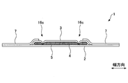
- FIG. 1 is a cross-sectional view taken along the line II of an absorbent article according to an embodiment of the present invention. It is the elements on larger scale of the side area
- the absorbent article 1 includes a liquid-impervious back sheet 2, a liquid-permeable front sheet 3, and an absorbent body 4 provided between both the sheets 2 and 3. And a main body (absorbent article main body) 8 having.
- the absorbent body 4 may be wrapped with an encapsulating sheet 5 made of crepe paper or nonwoven fabric.
- the absorbent article 1 further has a hip hold part H, which will be described later, and a wing part W provided with a wing WG, and the gap between the hip hold part H and the wing part W is between It is an intermediate part M.
- the hip hold part H can be a part extending from the position corresponding to the rear end of the crotch part of the underwear when worn to the rear end of the absorbent article 1, and the wing part W is a terminal at the front of the wing WG. To the rear end of the wing WG.
- the absorbent article 1 When the absorbent article 1 is used, it is attached to the underwear so that the wing part W side faces the front direction and the hip hold part H side faces the rear direction.
- the main body 8 has an elongated shape having a predetermined length in the front-rear direction as a whole, and has a substantially constant width in a direction orthogonal to the front-rear direction.
- the absorbent article 1 has a substantially line-symmetric shape with respect to the center line CL extending in the front-rear direction.
- the outer edge of the back sheet 2 and the outer edge of the top sheet 3 are joined by an adhesive such as hot melt, or an adhesive means such as heat seal or ultrasonic seal.
- the side nonwoven fabric 7 is provided in the both sides by the side of the surface sheet 3 along the front-back direction (longitudinal direction), respectively.
- the side nonwoven fabric 7 partially protrudes to the side of the main body 8 and is laminated on the back sheet 2 which also protrudes to the side.
- the side nonwoven fabric 7 is bonded by an adhesive such as hot melt or an adhesive means such as heat seal or ultrasonic seal.
- a sheet material having at least water shielding properties such as an olefin resin sheet such as polyethylene or polypropylene can be used.
- a laminated nonwoven fabric obtained by laminating a nonwoven fabric on a polyethylene sheet or the like, or a laminated sheet of a nonwoven fabric that is substantially impervious to liquid by interposing a waterproof film can be used. Further, it is more desirable to use a material having moisture permeability from the viewpoint of preventing stuffiness.
- a sheet obtained by melt-kneading an inorganic filler in an olefin resin such as polyethylene or polypropylene to form a sheet and then stretching it in a uniaxial or biaxial direction can be obtained.
- a porous sheet can be used.
- the top sheet 3 is a liquid-permeable sheet that allows permeation of body fluids such as menstrual blood, vaginal discharge, and urine quickly.
- a porous or non-porous nonwoven fabric, a porous plastic sheet, or the like is preferably used as the surface sheet 3.
- the material fibers constituting the nonwoven fabric include olefins such as polyethylene and polypropylene, synthetic fibers such as polyester and polyamide, regenerated fibers such as rayon and cupra, and blended fibers thereof, and natural fibers such as cotton alone or Two or more types can be used in combination.
- the nonwoven fabric processing method include a spunlace method, a spunbond method, a thermal bond method, a melt blown method, and a needle punch method.
- the spunlace method is preferable in terms of flexibility and the spunbond method is preferable in that it can produce a nonwoven fabric rich in drape, and the thermal bond method is preferable in terms of the ability to manufacture a bulky and soft nonwoven fabric.
- a composite fiber such as a core-sheath fiber, a side-by-side fiber, or a split fiber having a fiber having a high melting point as a core and a fiber having a low melting point as a sheath can be used.
- the absorbent body 4 interposed between the back sheet 2 and the top sheet 3 is not limited as long as it is a material that can absorb and retain body fluid, but preferably contains cotton-like pulp and a water-absorbing polymer.
- a superabsorbent polymer SAP
- SAF superabsorbent fiber
- pulp examples include cellulose fibers such as chemical pulp obtained from wood and dissolved pulp, and artificial cellulose fibers such as rayon and acetate.
- raw materials for chemical pulp hardwood, softwood, etc. are used, but softwood is preferably used because of its long fiber length.
- synthetic fibers may be mixed in the absorbent body 4.
- synthetic fibers polyolefins such as polyethylene and polypropylene, polyesters such as polyethylene terephthalate and polybutylene terephthalate, polyamides such as nylon, and copolymers thereof can be used. It can also be used.
- composite fibers such as a core-sheath fiber, a side-by-side fiber, and a split fiber having a fiber having a high melting point as a core and a fiber having a low melting point as a sheath can also be used.
- a hydrophobic fiber that has been surface treated with a hydrophilizing agent to impart affinity to body fluids.
- the thickness of the absorber 4 is preferably in the range of about 0.5 to 25 mm.
- the absorber 4 does not need to have a uniform thickness over the front surface, and may have a structure in which a portion corresponding to a body fluid discharge site is bulged.
- the absorbent body 4 is preferably manufactured by a stacking fiber or an airlaid method.
- a water-repellent treated nonwoven fabric or a hydrophilic treated nonwoven fabric can be used.
- a water repellent nonwoven fabric coated with a silicon-based, paraffin-based, alkylchromic chloride-based water repellent or the like when improving the absorptivity such as menstrual blood in the hip hold part H, it is preferable to use a hydrophilic nonwoven fabric as the nonwoven fabric material.
- a soft air-through nonwoven fabric which is difficult to crease and does not easily wrinkle is preferable.
- a dot emboss or a predetermined An embossed portion having an emboss having a shape can be provided.
- the main body 8 can be provided with a pressing groove (fit emboss) 16 for improving adhesion to the body and preventing leakage.
- a pressing groove fit emboss
- the front pressing groove 16 a disposed mainly in front of the wing part W
- the central pressing groove 16 b extending in the front-rear direction so as to surround the body fluid discharge part corresponding region 13, and mainly disposed in the hip hold part H.
- the first rear pressing groove 16c and the second rear pressing groove 16d corresponding to the flange portion are arranged from the cracked portion.
- the absorbent article 1 of this embodiment includes a hip hold part H.
- the hip hold part H is an area expansion part formed by increasing the length and width of the part extending from the rear side to the rear end part of both sides of the absorbent article 1, and as shown in FIG. By being fixed to the inner surface side of the buttocks, it has a function of preventing leakage of body fluid from the rear and / or obliquely rear of the absorbent article 1.
- the hip-hold portion H is a flap-like portion in which the side nonwoven fabric 7 and the back sheet 2 are laminated extending from the rear side to the rear end portion of the main body 8 of the absorbent article 1. including.
- the hip hold part H has a side part region 10 protruding from the rear side part of the main body 8 and a rear part region 11 protruding from the rear end part of the main body 8.
- the side region 10 of the hip hold portion H includes a region mainly formed by bonding the back sheet 2 and the side nonwoven fabric 7, and the back region 11 is mainly formed by bonding the back sheet 2 and the top sheet 3. Including the configured area.
- the side region 10 and the rear region 11 of the hip hold portion H do not have the absorber 4 and are configured to be thinner than the main body 8. Thereby, it is possible to move more flexibly than the main body 8.
- an absorbent body that is thinner than the absorbent body 4 used in the main body 8 can be laminated between the back sheet 2 and the side nonwoven fabric 7 in the hip hold part H.
- the hip-hold portion H can be a portion that extends to the rear end of the absorbent article 1 starting from a position corresponding to the rear end of the crotch portion of the underwear when worn.
- the hip hold portion H is a portion extending in the front-rear direction from the position where the front end of the second convex portion 22 adjacent to the front of the second concave portion 32 is located to the rear end of the absorbent article 1.
- the length of the hip hold part H in the front-rear direction is preferably, for example, 5 to 20 cm, and more preferably 8 to 18 cm.
- the total length of the absorbent article 1 may be 27 cm or more, 30 cm or more, and 45 cm or less.
- the length in the front-rear direction of the hip hold part H with respect to the total length is preferably 10 to 50%.
- the hip hold portion H includes a portion where the width of the absorbent article 1 is the largest, and the width is preferably 12 to 23 cm.
- the hip hold part H is provided with irregularities on its outer periphery (outline).
- the hip hold portion H includes a first convex portion 21 including a portion having the largest width from the center line in the front-rear direction of the main body 8 in the side region 10, and the first convex portion 21. It has the 1st recessed part 31 adjacent to back, and the 2nd recessed part 32 adjacent to the front rather than the 1st convex part 21.
- the hip hold portion H may also be provided with irregularities in the rear region 11 protruding from the rear end portion of the main body.
- the hip hold part H is planar as a whole.
- the heel part has a curved surface shape. Therefore, due to the difference between the planar shape and the curved surface shape, particularly the outer peripheral region (side part of the hip-hold part H)
- the region 10 and the rear region 11) may be distorted and wrinkled.
- the size and number of wrinkles that are generated are related to the area (area) of the entire hip hold part H and the shape of the curved surface of the hip part, but the above-mentioned convex parts and concave parts are not formed on the outer periphery of the hip hold part H. Wrinkles and twists may occur at a plurality of locations in the outer peripheral area of the hip hold part H.
- wrinkles touch the skin of the buttocks, it gives a sense of incongruity, especially when sitting on a chair for a long time or sleeping on the back on the night, part of the weight is added to the buttocks, Discomfort or discomfort increases.
- wrinkles can be further increased by changing the size of the weight applied to the buttocks and the contact state between the buttocks and the hip-holding portion H due to a change in posture while sleeping or a change in posture while sitting.
- body fluid tends to leak to the outside through the gaps caused by such wrinkles.
- the outer shape of the hip hold portion H includes the first convex portion 21 and the first concave portion 31 and the second concave portion 32 provided on both sides thereof. Even if a force that generates wrinkles is applied to the first convex portion 21, such force does not propagate to the entire hip hold portion H. 2 stays up to the recess 32. Therefore, for example, when wrinkles are generated, it is possible to prevent the wrinkles from propagating to a region of the intermediate portion M near the leg periphery that is likely to cause discomfort. That is, the first convex portion 21 can be independently deformed without greatly affecting both sides thereof.
- the hip-hold portion H when the hip-hold portion H is applied along the curved surface of the buttocks when the absorbent article is mounted, the hip-hold portion H can be deformed along the curved surface of the buttocks. Thereby, the fitting property to the buttocks of the hip hold part H can be improved.
- the radius of curvature of the first convex portion 21 can be 25 to 35 mm
- the radius of curvature of the first concave portion 31 can be 15 to 25 mm
- the radius of curvature of the second concave portion 32 can be 10 to 20 mm.
- the radius of curvature of the second concave portion 32 may be 36 to 46 mm.
- the radius of curvature of the third convex portion 23 adjacent to the rear of the first concave portion 31 is formed, the radius of curvature of the third convex portion 23 can be set to 30 to 40 mm.
- the side region 10 of the hip hold portion H can be provided with 1 to 5 convex portions and can be provided with 2 to 5 concave portions.
- This form is an individual absorbent article, that is, the absorbent article 1 individually packaged so that it can be conveniently and hygienically carried.
- the individual absorbent article has the above-described absorbent article 1 and the packaging sheet 18.
- the packaging sheet 18 preferably has a shape that can wrap the absorbent article 1.
- the packaging sheet 18 may be rectangular in plan view as shown in FIGS. 5A to 5E described later. Moreover, it is good also as shapes, such as a square, by planar view.
- the packaging sheet 18 is made of a polyolefin film such as polypropylene or polyethylene, a film such as polyester or polyvinyl alcohol, a non-woven fabric, a laminated non-woven fabric (including a polylaminated non-woven fabric), or the like. If emphasis is placed on the design by printing, a film is preferable, and if emphasis is placed on texture or soft feeling, non-woven fabric is preferable.
- the individual absorbent article is folded and individually packaged, and is preferably folded into three or more folds, preferably four or more folds, along a fold line substantially orthogonal to the front-rear direction. By making it into four or more folds (three or more fold lines), even an absorbent article with a long product length can be made into a compact form with a short length, which makes it easy to carry and store.
- the side region 10 of the hip hold portion H and the wing WG inward along the side edge of the main body 8. That is, for example, it is preferable to fold so as to form a fold line L0 (FIG. 5A) described later extending in the front-rear direction. If the side extension is folded in this way, it does not get in the way when carrying. Since the side region 10 and the wing WG of the hip hold portion H are thin flap portions, the folding along the front-rear direction of this portion is performed before the folding along the folding line substantially orthogonal to the front-rear direction. If it has been performed, unnecessary wrinkles and the like are less likely to occur in the side region 10 of the hip hold portion H and the wing WG.
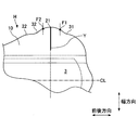
- FIG. 3 shows an enlarged view of a region including a part of one side region 10 of the hip hold portion H.
- the mountain fold line Y includes a first inflection point F ⁇ b> 1 between the first concave portion 31 and the first convex portion 21, and a first inflection point between the first convex portion 21 and the second concave portion 32. It intersects with the edge of the side region 10 of the hip hold portion H between the two inflection points F2 and is substantially orthogonal to the center line CL in the front-rear direction. That is, the fold line Y formed in the hip hold part H can be said to be a line that is substantially orthogonal to the front-rear direction center line CL, particularly in the vicinity of the apex of the first convex part 21 having the largest width.
- the mountain fold line is a line folded so as to protrude in a mountain shape on the front side of the absorbent article 1 (side on which the surface sheet 3 is provided).
- being substantially orthogonal to the center line CL in the front-rear direction does not mean strictly orthogonal, but may be, for example, an angle of ⁇ 15 ° or less with respect to the center line in the front-rear direction, and an angle of ⁇ 5 ° or less It is preferable that
- the mountain fold line Y is preferably formed within a range separated by 15 mm or less from the apex of the first convex portion 21 in the forward direction or the backward direction, and is formed within a range separated by a distance of 8 mm or less. More preferably, it is more preferably formed within a range separated by a distance of 5 mm or less.
- the mountain fold line Y is more preferably a line that passes through the apex of the first convex portion 21 and is orthogonal to the front-rear direction center line CL. Further, the mountain fold line Y may be a line extending to the vicinity of the side edge of the main body 8 and extends to the line extending to the nearest front-rear fold line L0 or the side edge of the main body 8. The existing line is preferable.
- wrinkles and twists are randomly (irregularly deep) in the side region 10 and the rear region 11 of the hip hold portion H. Easy to enter (by length and length). This tendency is particularly great in the first convex portion 21 having the largest width in the side region 10. Such wrinkles or the like in the first convex portion 21 may cause a sense of discomfort when hitting the skin.
- the absorbent article 1 is folded so that the mountain fold line Y is formed in the vicinity of the first convex portion 21 of the side region 10 of the hip hold portion H.
- This mountain fold line Y is maintained even when the absorbent article 1 is opened from the individual packaging state, that is, the fold of the mountain fold line Y is in a state of protruding to the surface sheet 3 side. .
- the protruding portion of the mountain fold line Y protrudes toward the buttock side and comes into contact with the skin first.
- the protruding part of the mountain fold line Y is immediately pushed to the underwear side by the force from the buttocks. If it does so, the area
- the first convex portion 21 is a region having the maximum width in the absorbent article 1, irregular wrinkles and the like that can be formed on the first convex portion 21 can directly lead to the occurrence of a sense of incongruity.
- wrinkles and the like in the first convex portion 21 having such a large area can be suppressed by this embodiment, so that the wearing feeling can be improved.
- the wrinkles and the like are concave portions where stress is likely to concentrate, for example, first concave portions. 31 and the second recess 32. Since the concave portion has a shorter length in the width direction than the convex portion, even if wrinkles occur in the concave portion, the length of the wrinkles also decreases, and the uncomfortable feeling caused by the wrinkles of such concave portions occurs in the convex portion having a large width. Smaller than the wrinkles.
- the side region 10 of the hip hold portion H is provided with irregularities, and the mountain fold line Y is formed in the vicinity of the first convex portion 21. Since it is folded, the fit to the body is high, and a sense of incongruity is well prevented or reduced.
- the mountain fold line Y may extend continuously from the apex of the first convex portion 21 to the side edge of the main body 8, or may not extend continuously.
- it may be a line that terminates in the middle of the first convex portion 21 from the vicinity of the apex of the first convex portion 21 as shown in the figure.
- the mountain fold line Y intersects with the edge of the side region 10 of the hip hold portion H between the first inflection point F1 and the second inflection point F2, and extends to the front-rear direction center line CL. If it is substantially orthogonal, a plurality may be provided, but if the number increases, the mountain fold line Y itself may cause a sense of incongruity, and it will reduce the sense of incongruity by extending random wrinkles etc. to the surrounding area Since there is a possibility of hindering the effect, it is preferable that the number of mountain fold lines Y is one, and it is preferable that the number is 3 or less at most.
- the side region 10 of the hip hold portion H is preferably folded at the front-rear fold line L0 (FIG. 5A) as described above.
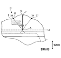
- the positional relationship between the mountain fold line Y and the first concave portion 31 and the second concave portion 32 will be described with reference to an enlarged view of a region including a part of one side region 10 of the hip hold portion H shown in FIG. To do.
- the angle ⁇ 1 formed with the extension line) is preferably 30 ° to 60 °, more preferably 35 ° to 45 °.
- the angle ⁇ 2 formed by the straight line X2 passing through the intersection A and the bottom of the second recess 32 and the mountain fold line Y is preferably 30 ° to 60 °, and preferably 35 ° to 45 °. More preferably.
- the bottom point of the first recess 31 is the bottom point of the recess between the first protrusion 21 and the third protrusion 23 adjacent to the first recess 31, and the first protrusion
- a line in contact with both the portion 21 and the third convex portion 23 a line passing through the vertex of the first convex portion 21 and the vertex of the third convex portion 23
- a perpendicular is drawn from the line to the first concave portion 31.
- the vertical line can be the longest position.
- the bottom point of the second recess 32 is the bottom point of the recess between the first projection 21 and the second projection 22 adjacent to the second recess 32, and the first projection 21 and the second projection
- a perpendicular line is drawn from the line to the third concave portion 32. It can be set as the position where the length becomes the longest.
- the first protrusion Even when a force for generating wrinkles or the like is applied to 21, an appropriate range in which the force can be released to the surroundings can be secured on both sides of the first convex portion 21. That is, by setting the angles ⁇ 1 and ⁇ 2 to 30 ° or more, wrinkles or the like are prevented from being generated at a position close to the first convex portion 21 to increase the sense of discomfort, and by setting the angles ⁇ 1 and ⁇ 2 to 60 ° or less, the stress is reduced. Even if it is excessively concentrated to cause wrinkles or the like, the effect of collecting wrinkles in the recesses can be obtained.
- the above angles ⁇ 1 and ⁇ 2 may be the same or different.
- the buttocks easily move relative to the front from the rear of the hip hold part H, and the skin tends to come into close contact with the hip hold part H particularly near the front of the first convex part 21.
- the angle ⁇ 2 is larger than the angle ⁇ 1, a stretching effect is exerted over a wider range in front of the first convex portion 21, and irregular wrinkles can be prevented. .
- the back sheet 2 of the hip hold part H may be provided with a slip stopper 9 for fixing the absorbent article 1.
- the slip stopper 9 is an adhesive or non-adhesive layer, and the hip hold part H and the undergarment are coupled through this layer, and the hip hold part H is prevented from being displaced from a predetermined position in the undergarment.
- the slip stopper 9 can be formed as an adhesive or non-adhesive layer.
- the adhesive layer for example, a layer mainly composed of a styrene polymer, a tackifier, a plasticizer, and a combination thereof is preferably used.
- examples of the tackifier and the plasticizer include various petroleum resins and ester polymers that are solid at room temperature.
- an elastomer such as rubber can be used.
- the slip stopper 9 can be disposed at a position close to the bottom of the second recess 32.
- the slip stopper 9 is disposed so as to straddle a straight line X2 passing through the intersection A between the above-described mountain fold line Y (or an extension thereof) and the front-rear fold line L0 and the bottom point of the second recess 32. It is preferable. Thereby, even when stress is excessively concentrated in the vicinity of the second recess 32, the region in the vicinity of the second recess 32 is fixed to the underwear and the stress is dispersed, so that wrinkles are generated or large wrinkles are generated. This can be prevented or reduced.
- the slip stopper 9 is formed in the vicinity of the second recess 32 that is relatively close to the periphery of the leg, it can contribute to prevention of wrinkles and twisting around the leg, which is likely to cause a sense of incongruity. A comfortable fit can be maintained.
- the radius of curvature of the first convex portion 21 is larger than the radius of curvature of the first concave portion 31 and the radius of curvature of the second concave portion 32. That is, it is preferable that the constriction of the first recess 31 and the second recess 32 is deep. Thereby, in the 1st convex part 21, the mountain fold line Y by folding becomes easy to be formed. Therefore, even when a force that generates wrinkles or twists is generated in the first convex portion 21, the effect of releasing the wrinkles or twists to both sides thereof, that is, the first concave portion 31 and the second concave portion 32 is promoted. .
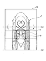
- the absorbent article 1 is folded in four in the front-rear direction of the absorbent article 1 together with the packaging sheet 18 and the release sheet 19 as shown in FIGS. 5A to 5E.
- folding in four even an absorbent article 1 having a large size can be easily carried.
- it can be tri-folded.
- the absorbent article 1 is placed on the packaging sheet 18 as shown in FIG. 5A.
- the packaging sheet 18 has a width that is substantially the same as or larger than the larger one of the maximum width of the hip hold portion H and the maximum width of the wing portion W.
- the length of the front-back direction of the packaging sheet 18 does not necessarily need to be larger than the length of the front-back direction of the absorbent article 1.
- the front end portion of the packaging sheet 18 be disposed in front of the front end portion of the absorbent article 1.
- the flap-shaped portion extending outward from the side edge of the main body 8, that is, the side region 10 of the hip hold portion H and the wing WG are indicated by arrows in FIG. Fold inward (to the top sheet 3 side).
- a side fold line is attached to the side edge portion of the main body 8 along the front-rear direction, and when the absorbent article 1 is taken out from the package and attached, the side region 10 of the hip hold portion H is attached. Since it will be shaped in the direction of wrapping the buttocks, the fit can be further improved.
- the release sheet 19 is placed on the slip stopper 9 in order to protect the slip stopper 9 from sticking.
- the state after disposing the release sheet 19 is shown in FIG. 5B.
- the release sheet 19 can have a rectangular shape as shown in FIG. 5B, but is not limited to a rectangular shape as long as it can be disposed so as to cover the misalignment stopper 9 in the process of folding. It may be a shape. Further, a plurality of release sheets 19 may be arranged so as to cover the slip stoppers 9 in the side regions 10 of the wing WG and the hip hold part H, respectively.
- Examples of the release sheet 19 include paper having a release treatment applied to the surface on which the anti-slip material 9 abuts, a polyolefin film such as polypropylene and polyethylene, a film such as polyester and polyvinyl alcohol, a nonwoven fabric, and a laminated nonwoven fabric (polylaminate). Nonwoven fabric) can be used.
- Said mold release process can be formed by apply
- coating or spray-applying mold release process liquids such as a silicone type resin, a fluorine resin, or a tetrafluoroethylene type resin.
- FIG. 5C shows a state after the folding at the first folding line L1.
- the first fold line L1 is folded so that a mountain fold line Y is formed in the side region 10 of the hip hold part H.
- the mountain fold line Y is formed by the first recess 31.
- the mountain fold line Y is preferably formed so as to extend in a direction passing through the apex of the first convex portion 21 and perpendicular to the center line CL.
- FIG. 5D shows the state after folding along the second fold line.
- the second fold line L2 may be a line that crosses the intermediate part M located behind the wing part W in the width direction, but the body fluid discharge part corresponding region 13 (FIG. 1) when the absorbent article 1 is bent by folding. ) Is not on the body fluid discharge part corresponding region 13 so as not to impair the absorption performance.
- the pressing groove 16 especially the 1st back pressing groove 16c (FIG. 1) corresponding to a collar part from a crack part breaks and impairs the function, it provides before the 1st back pressing groove 16c. It is preferable that
- FIG. 5D shows a state where the absorbent article is folded at the third fold line L3.
- both side edges of the packaging sheet 18 can be sealed by embossing, heat fusion, adhesive, or the like.
- the front end of the packaging sheet 18 of the individual absorbent article can be fixed with a seal tape, emboss crimping, heat fusion, adhesive, or the like, and the individual package can be prevented from opening from the front end.
- the side region 10 of the hip hold part H and the wing WG of the wing part W are folded inward as indicated by the arrows in FIG. 5A, and then the entire absorbent article 1 is folded in the front-rear direction. Yes.
- the side region 10 of the hip hold part H and the wing WG of the wing part W are folded in the direction opposite to the direction indicated by the arrow in FIG. 5A. Can be folded outward (toward the back sheet 2). Even when the side edge portion is folded outward as described above, if the topsheet 3 is folded in the front-rear direction so as to be inside as in the above-described procedure, the side region 10 of the hip hold portion H A mountain fold line Y can be formed.
- the first fold line L1 can be 30 to 200 mm from the rear end of the absorbent article 1.
- the second fold line L2 is preferably arranged at a position 120 to 350 mm from the rear end of the absorbent article 1.
- the third fold line L3 is preferably 50 to 100 mm from the front end of the absorbent article 1.
- the slip stopper 9 is disposed in advance on the back sheet 2 side of the absorbent article 1, and the release sheet 19 is disposed so as to cover the slip stopper 9.
- 9 can be provided not on the absorbent article 1 but on the release sheet 19. That is, when the release sheet 19 is overlapped with the absorbent article 1 folded inward at the front and rear fold line L0, it corresponds to a desired position in the side region 10 of the wing WG and the hip hold part H of the absorbent article 1.
- the slip prevention material 9 is provided on the release sheet 19.
- the release sheet 19 with the slip stopper 9 is placed on the absorbent article 1 folded inward at the front-rear fold line L0 so that the side on which the slip stopper 9 is provided faces the absorbent article 1.
- the first fold line L1, the second fold line L2, and the third fold line L3 can be folded in order.
- the anti-slip material 9 is provided on the release sheet 19 in advance as described above, by applying an adhesive to the surface of the anti-slip material 9 facing the absorbent article 1, the anti-slip material 9 is provided. Can be fixed to the back sheet 2 of the absorbent article 1.
- the mountain fold line Y is formed by folding during individual packaging, but may be an absorbent article in which the mountain fold line Y is formed in advance.
- the mountain fold line Y can be formed by folding or pressing.
- the mountain fold line Y can be processed and formed at least in the side region 10 of the hip hold portion H in a state where the absorbent article 1 is spread.
- the mountain fold line Y When the mountain fold line Y is formed in advance, for example, it can be individually packaged in the state shown in FIG. 5B without being folded in the longitudinal direction. That is, at two folding lines L0 in the front-rear direction, a flap-shaped portion extending outward from the side edge of the main body 8, that is, a portion including the side region 10 of the hip hold portion H and the wing WG is folded inward. Can be individually packaged in a state.
- the width of the packaging sheet 18 may be substantially the same as the width of the absorbent article 1 (approximately the width of the main body 8) after being folded inward or outward along the front-rear fold line L0.
- the absorbent article 1 folded at two fold lines L0 in the front-rear direction can be laminated and packaged together. Thereby, it can be packaged and transported in a thin state and without being bulky in a stacked state. Moreover, since the taking-out time and labor can be saved, it is useful in applications where the absorbent article 1 is used one after another in large quantities.
Landscapes
- Health & Medical Sciences (AREA)
- Epidemiology (AREA)
- Engineering & Computer Science (AREA)
- Biomedical Technology (AREA)
- Heart & Thoracic Surgery (AREA)
- Vascular Medicine (AREA)
- Life Sciences & Earth Sciences (AREA)
- Animal Behavior & Ethology (AREA)
- General Health & Medical Sciences (AREA)
- Public Health (AREA)
- Veterinary Medicine (AREA)
- Mechanical Engineering (AREA)
- Manufacturing & Machinery (AREA)
- Absorbent Articles And Supports Therefor (AREA)
Abstract
Description
吸収性物品1は、図1及び図2に示すように、不透液性の裏面シート2と、透液性の表面シート3と、これら両シート2、3間に設けられた吸収体4とを有する本体(吸収性物品本体)8とを備えている。吸収体4の形状保持等のために、吸収体4は、クレープ紙又は不織布等からなる被包シート5によって包まれていてもよい。吸収性物品1は、さらに、図1に示すように、後述のヒップホールド部Hと、ウィングWGを備えたウィング部Wとを有しており、ヒップホールド部Hとウィング部Wとの間は中間部Mとなっている。ヒップホールド部Hは、装着時に下着のクロッチ部分の後端に対応する位置を起点として、吸収性物品1の後端まで延びる部分とすることができ、ウィング部Wは、ウィングWGの前方の終端からウィングWGの後方の終端までの領域とすることができる。
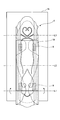
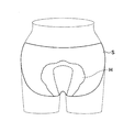
本形態の吸収性物品1は、ヒップホールド部Hを備えている。ヒップホールド部Hは、吸収性物品1の両側部後方から後端部にわたる部分の長さ及び幅を大きくすることによって形成された面積拡張部分であり、図6に示すように、装着時に下着Sの臀部内面側に固定されることで、吸収性物品1の後方及び/又は斜め後方からの体液の漏れを阻止する機能を有する。ヒップホールド部Hは、図1に示すように、吸収性物品1の本体8の両側部の後方から後端部にかけて延在する、サイド不織布7と裏面シート2とが積層されたフラップ状の部分を含む。
ヒップホールド部Hには、その外周(外形線)に凹凸が設けられている。例えば、ヒップホールド部Hは、図1に示すように、側部領域10において、本体8の前後方向中心線からの幅が最も大きい部分を含む第1凸部21と、第1凸部21より後方に隣接する第1凹部31と、第1凸部21より前方に隣接する第2凹部32とを有する。また、ヒップホールド部Hには、図1に示すように、本体の後端部から突出する後部領域11にも凹凸が設けられていてよい。
本形態は、個装吸収性物品、つまり、都合良く且つ衛生的に携帯することが可能であるように個別に包装された吸収性物品1である。個装吸収性物品は、上述の吸収性物品1と、包装シート18とを有する。
本形態の吸収性物品1は、ヒップホールド部Hの側部領域10に山折り線Yが形成されるように折られている。図3に、ヒップホールド部Hの一方の側部領域10の一部を含む領域の拡大図を示す。図3に示すように、山折り線Yは、第1凹部31と第1凸部21との間の第1変曲点F1と、第1凸部21と第2凹部32との間の第2変曲点F2との間でヒップホールド部Hの側部領域10の縁部と交差し且つ前後方向の中心線CLに略直交している。つまり、ヒップホールド部Hに形成される折り線Yは、最も幅の大きい第1凸部21において、特にその頂点付近に、前後方向中心線CLに略直交する線と言える。
図1、図4に示すように、ヒップホールド部Hの裏面シート2には、吸収性物品1を固定するためのズレ止め材9が設けられていてよい。ズレ止め材9は、粘着性又は非粘着性の層であり、この層を介してヒップホールド部Hと下着とを結合させ、ヒップホールド部Hが下着における所定位置からズレることを抑制する。
以下、吸収性物品1を折り畳む方法を具体的に示す。
2 裏面シート
3 表面シート
4 吸収体
5 被包シート
7 サイド不織布
8 本体(吸収性物品本体)
9 ズレ止め材
10 側部領域
11 後部領域
13 体液排出部対応領域
16a~16d 圧搾溝
18 包装シート
19 剥離シート
21 第1凸部
22 第2凸部
23 第3凸部
31 第1凹部
32 第2凹部
A 前後方向折り線と山折り線との交点
CL 前後方向中心線
H ヒップホールド部
L0 前後方向折り線
L1 第1折り線
L2 第2折り線
L3 第3折り線
M 中間部
S 下着
W ウィング部
WG ウィング
Y 山折り線
Claims (5)
- 透液性の表面シートと、不透液性の裏面シートと、前記表面シートと前記裏面シートとの間に設けられた吸収体とを有する本体を含む吸収性物品と、
前記吸収性物品を個装する包装シートと
を含む個装吸収性物品であって、
前記本体は、前後方向に所定の長さ及び当該前後方向と直交する方向に所定の幅を有する形状であり、
前記吸収性物品がヒップホールド部を有しており、当該ヒップホールド部は、前記本体の後方側部から突出する側部領域において、前記本体の前後方向中心線からの幅が最も大きい部分を含む第1凸部と、前記第1凸部より後方に隣接する第1凹部と、前記第1凸部より前方に隣接する第2凹部とを有し、
前記吸収性物品は、前記ヒップホールド部の側部領域に山折り線が形成されるように折られており、
前記山折り線は、前記第1凹部と前記第1凸部との間の第1変曲点と、前記第1凸部と前記第2凹部との間の第2変曲点との間で前記ヒップホールド部の側部領域の縁部と交差し且つ前記前後方向の中心線に略直交している、個装吸収性物品。 - 前記ヒップホールド部の前記側部領域が、前記前後方向に延びる前後方向折り線で折られており、
前記山折り線の延長線と前記前後方向折り線との交点と前記第1凹部の底点とを通る直線と、前記山折り線とのなす角度、及び
前記交点と前記第2凹部の底点とを通る直線と、前記山折り線とのなす角度が30°~60°である、請求項1に記載の個装吸収性物品。 - 前記側部領域の前記裏面シート側に、前記吸収性物品を固定するためのズレ止め材が設けられており、前記ズレ止め材は、前記交点と前記第2凹部の底点とを通る直線を跨るように配置されている、請求項2に記載の個装吸収性物品。
- 透液性の表面シートと、不透液性の裏面シートと、前記表面シートと前記裏面シートとの間に設けられた吸収体とを有する本体を含む吸収性物品であって、
前記本体は、前後方向に所定の長さ及び当該前後方向と直交する方向に所定の幅を有する形状であり、
ヒップホールド部を有しており、当該ヒップホールド部は、前記本体の後方側部から突出する側部領域において、前記本体の前後方向中心線からの幅が最も大きい部分を含む第1凸部と、前記第1凸部より後方に隣接する第1凹部と、前記第1凸部より前方に隣接する第2凹部とを有し、
前記ヒップホールド部の側部領域に山折り線が形成されており、
前記山折り線は、前記第1凹部と前記第1凸部との間の第1変曲点と、前記第1凸部と前記第2凹部との間の第2変曲点との間で前記ヒップホールド部の側部領域の縁部と交差し且つ前記前後方向の中心線に略直交している、吸収性物品。 - 透液性の表面シートと、不透液性の裏面シートと、前記表面シートと前記裏面シートとの間に設けられた吸収体とを有する本体を含む吸収性物品を折り畳む方法であって、
前記本体は、前後方向に所定の長さ及び当該前後方向と直交する方向に所定の幅を有する形状であり、
前記吸収性物品がヒップホールド部を有しており、当該ヒップホールド部は、前記本体の後方側部から突出する側部領域において、前記本体の前後方向中心線からの幅が最も大きい部分を含む第1凸部と、前記第1凸部より後方に隣接する第1凹部と、前記第1凸部より前方に隣接する第2凹部とを有し、
前記吸収性物品を、山折り線が前記ヒップホールド部の側部領域に形成されるように折ることを含み、
前記山折り線は、前記第1凹部と前記第1凸部との間の第1変曲点と、前記第1凸部と前記第2凹部との間の第2変曲点との間で前記ヒップホールド部の側部領域の縁部と交差し且つ前記前後方向の中心線に略直交している、吸収性物品を折り畳む方法。
Priority Applications (5)
| Application Number | Priority Date | Filing Date | Title |
|---|---|---|---|
| CN201780070627.6A CN109952081B (zh) | 2016-11-25 | 2017-10-24 | 独立包装吸收性物品、吸收性物品以及折叠吸收性物品的方法 |
| US16/348,246 US11357672B2 (en) | 2016-11-25 | 2017-10-24 | Individually packaged absorbent article, absorbent article, and method for folding absorbent article |
| KR1020197014143A KR102398459B1 (ko) | 2016-11-25 | 2017-10-24 | 개별 포장 흡수성 물품, 흡수성 물품, 및 흡수성 물품을 접는 방법 |
| EP17873189.9A EP3545921B1 (en) | 2016-11-25 | 2017-10-24 | Individually packaged absorbent article, absorbent article, and method for folding absorbent article |
| RU2019114689A RU2737307C1 (ru) | 2016-11-25 | 2017-10-24 | Индивидуально упакованное впитывающее изделие, впитывающее изделие и способ для складывания впитывающего изделия |
Applications Claiming Priority (2)
| Application Number | Priority Date | Filing Date | Title |
|---|---|---|---|
| JP2016229538A JP6360539B2 (ja) | 2016-11-25 | 2016-11-25 | 個装吸収性物品、吸収性物品、及び吸収性物品を折り畳む方法 |
| JP2016-229538 | 2016-11-25 |
Publications (1)
| Publication Number | Publication Date |
|---|---|
| WO2018096865A1 true WO2018096865A1 (ja) | 2018-05-31 |
Family
ID=62196037
Family Applications (1)
| Application Number | Title | Priority Date | Filing Date |
|---|---|---|---|
| PCT/JP2017/038403 Ceased WO2018096865A1 (ja) | 2016-11-25 | 2017-10-24 | 個装吸収性物品、吸収性物品、及び吸収性物品を折り畳む方法 |
Country Status (8)
| Country | Link |
|---|---|
| US (1) | US11357672B2 (ja) |
| EP (1) | EP3545921B1 (ja) |
| JP (1) | JP6360539B2 (ja) |
| KR (1) | KR102398459B1 (ja) |
| CN (1) | CN109952081B (ja) |
| RU (1) | RU2737307C1 (ja) |
| TW (1) | TWI765935B (ja) |
| WO (1) | WO2018096865A1 (ja) |
Cited By (1)
| Publication number | Priority date | Publication date | Assignee | Title |
|---|---|---|---|---|
| CN116459082A (zh) * | 2019-01-23 | 2023-07-21 | 宝洁公司 | 适于隐蔽携带和取用的包装女性卫生护垫产品及制造方法 |
Families Citing this family (10)
| Publication number | Priority date | Publication date | Assignee | Title |
|---|---|---|---|---|
| WO2018006946A1 (en) | 2016-07-05 | 2018-01-11 | Sca Hygiene Products Ab | Absorbent article having an improved fastening system and a method to manufacture such absorbent article |
| US11540957B2 (en) * | 2017-05-26 | 2023-01-03 | Kimberly-Clark Worldwide, Inc. | Absorbent article with pivotable wings |
| JP2020048947A (ja) * | 2018-09-27 | 2020-04-02 | 大王製紙株式会社 | 個装吸収性物品 |
| US12115050B2 (en) * | 2018-12-13 | 2024-10-15 | Essity Hygiene And Health Aktiebolag | Male incontinence guard, kit, and method |
| USD963846S1 (en) * | 2019-10-11 | 2022-09-13 | Zhuhai Jianlang Daily Necessities Co., Ltd. | Anti-leakage sanitary napkin |
| JP7429617B2 (ja) * | 2020-07-28 | 2024-02-08 | 大王製紙株式会社 | 個装吸収性物品、及び個装吸収性物品の製造方法 |
| USD964555S1 (en) * | 2020-11-02 | 2022-09-20 | Productos Familia S.A. | Absorbent article |
| AU2020484051A1 (en) * | 2020-12-29 | 2023-07-13 | Essity Hygiene And Health Aktiebolag | Sanitary article with embossed functional design elements |
| AU2020484181A1 (en) * | 2020-12-29 | 2023-07-13 | Essity Hygiene And Health Aktiebolag | Disposable hygiene article with improved fit |
| USD1092727S1 (en) | 2021-06-21 | 2025-09-09 | Essity Hygiene And Health Aktiebolag | Sanitary napkin |
Citations (5)
| Publication number | Priority date | Publication date | Assignee | Title |
|---|---|---|---|---|
| JPS5947517B2 (ja) | 1976-12-21 | 1984-11-19 | ソニー株式会社 | Pal−ntsc信号変換装置 |
| JP3871611B2 (ja) | 2002-05-30 | 2007-01-24 | 花王株式会社 | 吸収性物品 |
| JP2010082061A (ja) * | 2008-09-30 | 2010-04-15 | Daio Paper Corp | 吸収性物品 |
| JP2011172658A (ja) * | 2010-02-23 | 2011-09-08 | Daio Paper Corp | 吸収性物品 |
| JP5082007B1 (ja) | 2011-09-30 | 2012-11-28 | ユニ・チャーム株式会社 | 吸収性物品 |
Family Cites Families (19)
| Publication number | Priority date | Publication date | Assignee | Title |
|---|---|---|---|---|
| US5358500A (en) * | 1993-06-03 | 1994-10-25 | The Procter & Gamble Company | Absorbent articles providing sustained dynamic fit |
| KR20020059363A (ko) * | 1999-08-16 | 2002-07-12 | 웰피엘드 마크 | 흡수성 생리대 |
| US6464675B2 (en) * | 2000-12-19 | 2002-10-15 | Johnson & Johnson Industria E Comercio Ltda | Sanitary napkin |
| US20020143309A1 (en) * | 2001-03-30 | 2002-10-03 | Tara Glasgow | Dynamic fitting compound sanitary napkin |
| JP4476611B2 (ja) * | 2003-05-29 | 2010-06-09 | ユニ・チャーム株式会社 | 生理用ナプキン |
| JP4540104B2 (ja) * | 2004-11-30 | 2010-09-08 | 大王製紙株式会社 | 吸収性物品 |
| CN1788702B (zh) * | 2004-12-15 | 2011-05-25 | 花王株式会社 | 吸收性物品的包装结构 |
| US7811271B2 (en) * | 2005-09-09 | 2010-10-12 | The Procter & Gamble Company | Absorbent article having flap activation |
| JP4580905B2 (ja) * | 2006-06-30 | 2010-11-17 | 大王製紙株式会社 | 吸収性物品 |
| JP5947517B2 (ja) | 2011-10-20 | 2016-07-06 | 花王株式会社 | 吸収性物品 |
| JP6031444B2 (ja) * | 2011-10-31 | 2016-11-24 | 大王製紙株式会社 | 吸収性物品 |
| JP6219573B2 (ja) * | 2013-01-31 | 2017-10-25 | ユニ・チャーム株式会社 | 吸収性物品 |
| JP2014208545A (ja) | 2013-03-29 | 2014-11-06 | ユニ・チャーム株式会社 | 吸収性物品の収容体 |
| JP6169413B2 (ja) * | 2013-05-16 | 2017-07-26 | ユニ・チャーム株式会社 | 吸収性物品 |
| JP6005124B2 (ja) * | 2014-12-01 | 2016-10-12 | ユニ・チャーム株式会社 | 吸収性物品 |
| JP6126182B2 (ja) * | 2015-09-07 | 2017-05-10 | ユニ・チャーム株式会社 | 吸収性物品の個包装体 |
| JP6263581B1 (ja) * | 2016-07-27 | 2018-01-17 | 大王製紙株式会社 | 吸収性物品 |
| JP6211151B1 (ja) * | 2016-07-27 | 2017-10-11 | 大王製紙株式会社 | 吸収性物品 |
| JP6263584B1 (ja) * | 2016-08-25 | 2018-01-17 | 大王製紙株式会社 | 吸収性物品 |
-
2016
- 2016-11-25 JP JP2016229538A patent/JP6360539B2/ja active Active
-
2017
- 2017-10-24 EP EP17873189.9A patent/EP3545921B1/en active Active
- 2017-10-24 KR KR1020197014143A patent/KR102398459B1/ko active Active
- 2017-10-24 WO PCT/JP2017/038403 patent/WO2018096865A1/ja not_active Ceased
- 2017-10-24 CN CN201780070627.6A patent/CN109952081B/zh active Active
- 2017-10-24 RU RU2019114689A patent/RU2737307C1/ru active
- 2017-10-24 US US16/348,246 patent/US11357672B2/en active Active
- 2017-11-22 TW TW106140466A patent/TWI765935B/zh active
Patent Citations (5)
| Publication number | Priority date | Publication date | Assignee | Title |
|---|---|---|---|---|
| JPS5947517B2 (ja) | 1976-12-21 | 1984-11-19 | ソニー株式会社 | Pal−ntsc信号変換装置 |
| JP3871611B2 (ja) | 2002-05-30 | 2007-01-24 | 花王株式会社 | 吸収性物品 |
| JP2010082061A (ja) * | 2008-09-30 | 2010-04-15 | Daio Paper Corp | 吸収性物品 |
| JP2011172658A (ja) * | 2010-02-23 | 2011-09-08 | Daio Paper Corp | 吸収性物品 |
| JP5082007B1 (ja) | 2011-09-30 | 2012-11-28 | ユニ・チャーム株式会社 | 吸収性物品 |
Non-Patent Citations (1)
| Title |
|---|
| See also references of EP3545921A4 |
Cited By (1)
| Publication number | Priority date | Publication date | Assignee | Title |
|---|---|---|---|---|
| CN116459082A (zh) * | 2019-01-23 | 2023-07-21 | 宝洁公司 | 适于隐蔽携带和取用的包装女性卫生护垫产品及制造方法 |
Also Published As
| Publication number | Publication date |
|---|---|
| KR20190087428A (ko) | 2019-07-24 |
| EP3545921A1 (en) | 2019-10-02 |
| JP6360539B2 (ja) | 2018-07-18 |
| US11357672B2 (en) | 2022-06-14 |
| TWI765935B (zh) | 2022-06-01 |
| CN109952081A (zh) | 2019-06-28 |
| CN109952081B (zh) | 2021-06-22 |
| JP2018083015A (ja) | 2018-05-31 |
| EP3545921B1 (en) | 2021-07-21 |
| KR102398459B1 (ko) | 2022-05-13 |
| RU2737307C1 (ru) | 2020-11-26 |
| US20190254890A1 (en) | 2019-08-22 |
| TW201818896A (zh) | 2018-06-01 |
| EP3545921A4 (en) | 2019-10-02 |
Similar Documents
| Publication | Publication Date | Title |
|---|---|---|
| JP6360539B2 (ja) | 個装吸収性物品、吸収性物品、及び吸収性物品を折り畳む方法 | |
| CN109640908B (zh) | 吸收性物品 | |
| JP6263581B1 (ja) | 吸収性物品 | |
| JP6162412B2 (ja) | 吸収性物品 | |
| JP6211151B1 (ja) | 吸収性物品 | |
| JP6375354B2 (ja) | 吸収性物品 | |
| WO2017217356A1 (ja) | 吸収性物品 | |
| JP2018086170A5 (ja) | ||
| JP6591833B2 (ja) | 吸収性物品 | |
| JP5780757B2 (ja) | 吸収性物品 | |
| JP6604777B2 (ja) | 吸収性物品 | |
| JP6371802B2 (ja) | 吸収性物品 | |
| JP5717379B2 (ja) | 吸収性物品 | |
| JP2018000283A5 (ja) | ||
| US20220110799A1 (en) | Individually wrapped absorbent article | |
| JP7516227B2 (ja) | 吸収性物品 | |
| JP2019041868A (ja) | 吸収性物品 | |
| JP6263585B1 (ja) | 吸収性物品 | |
| JP2019000530A (ja) | 吸収性物品、及び個装吸収性物品 |
Legal Events
| Date | Code | Title | Description |
|---|---|---|---|
| 121 | Ep: the epo has been informed by wipo that ep was designated in this application |
Ref document number: 17873189 Country of ref document: EP Kind code of ref document: A1 |
|
| ENP | Entry into the national phase |
Ref document number: 20197014143 Country of ref document: KR Kind code of ref document: A |
|
| NENP | Non-entry into the national phase |
Ref country code: DE |
|
| WWE | Wipo information: entry into national phase |
Ref document number: 2019114689 Country of ref document: RU |
|
| ENP | Entry into the national phase |
Ref document number: 2017873189 Country of ref document: EP Effective date: 20190625 |