WO2018096956A1 - 触感呈示装置 - Google Patents
触感呈示装置 Download PDFInfo
- Publication number
- WO2018096956A1 WO2018096956A1 PCT/JP2017/040625 JP2017040625W WO2018096956A1 WO 2018096956 A1 WO2018096956 A1 WO 2018096956A1 JP 2017040625 W JP2017040625 W JP 2017040625W WO 2018096956 A1 WO2018096956 A1 WO 2018096956A1
- Authority
- WO
- WIPO (PCT)
- Prior art keywords
- vibration
- target
- holding member
- actuator
- tactile sensation
- Prior art date
- Legal status (The legal status is an assumption and is not a legal conclusion. Google has not performed a legal analysis and makes no representation as to the accuracy of the status listed.)
- Ceased
Links
Images


Classifications
-
- G—PHYSICS
- G06—COMPUTING OR CALCULATING; COUNTING
- G06F—ELECTRIC DIGITAL DATA PROCESSING
- G06F3/00—Input arrangements for transferring data to be processed into a form capable of being handled by the computer; Output arrangements for transferring data from processing unit to output unit, e.g. interface arrangements
- G06F3/01—Input arrangements or combined input and output arrangements for interaction between user and computer
- G06F3/016—Input arrangements with force or tactile feedback as computer generated output to the user
-
- G—PHYSICS
- G06—COMPUTING OR CALCULATING; COUNTING
- G06F—ELECTRIC DIGITAL DATA PROCESSING
- G06F3/00—Input arrangements for transferring data to be processed into a form capable of being handled by the computer; Output arrangements for transferring data from processing unit to output unit, e.g. interface arrangements
- G06F3/01—Input arrangements or combined input and output arrangements for interaction between user and computer
- G06F3/03—Arrangements for converting the position or the displacement of a member into a coded form
- G06F3/033—Pointing devices displaced or positioned by the user, e.g. mice, trackballs, pens or joysticks; Accessories therefor
- G06F3/0354—Pointing devices displaced or positioned by the user, e.g. mice, trackballs, pens or joysticks; Accessories therefor with detection of two-dimensional [2D] relative movements between the device, or an operating part thereof, and a plane or surface, e.g. 2D mice, trackballs, pens or pucks
- G06F3/03547—Touch pads, in which fingers can move on a surface
-
- G—PHYSICS
- G06—COMPUTING OR CALCULATING; COUNTING
- G06F—ELECTRIC DIGITAL DATA PROCESSING
- G06F3/00—Input arrangements for transferring data to be processed into a form capable of being handled by the computer; Output arrangements for transferring data from processing unit to output unit, e.g. interface arrangements
- G06F3/01—Input arrangements or combined input and output arrangements for interaction between user and computer
- G06F3/03—Arrangements for converting the position or the displacement of a member into a coded form
- G06F3/041—Digitisers, e.g. for touch screens or touch pads, characterised by the transducing means
- G06F3/0414—Digitisers, e.g. for touch screens or touch pads, characterised by the transducing means using force sensing means to determine a position
-
- G—PHYSICS
- G06—COMPUTING OR CALCULATING; COUNTING
- G06F—ELECTRIC DIGITAL DATA PROCESSING
- G06F3/00—Input arrangements for transferring data to be processed into a form capable of being handled by the computer; Output arrangements for transferring data from processing unit to output unit, e.g. interface arrangements
- G06F3/01—Input arrangements or combined input and output arrangements for interaction between user and computer
- G06F3/03—Arrangements for converting the position or the displacement of a member into a coded form
- G06F3/041—Digitisers, e.g. for touch screens or touch pads, characterised by the transducing means
- G06F3/0416—Control or interface arrangements specially adapted for digitisers
-
- H—ELECTRICITY
- H10—SEMICONDUCTOR DEVICES; ELECTRIC SOLID-STATE DEVICES NOT OTHERWISE PROVIDED FOR
- H10N—ELECTRIC SOLID-STATE DEVICES NOT OTHERWISE PROVIDED FOR
- H10N30/00—Piezoelectric or electrostrictive devices
- H10N30/20—Piezoelectric or electrostrictive devices with electrical input and mechanical output, e.g. functioning as actuators or vibrators
-
- G—PHYSICS
- G06—COMPUTING OR CALCULATING; COUNTING
- G06F—ELECTRIC DIGITAL DATA PROCESSING
- G06F2203/00—Indexing scheme relating to G06F3/00 - G06F3/048
- G06F2203/041—Indexing scheme relating to G06F3/041 - G06F3/045
- G06F2203/04105—Pressure sensors for measuring the pressure or force exerted on the touch surface without providing the touch position
-
- H—ELECTRICITY
- H03—ELECTRONIC CIRCUITRY
- H03K—PULSE TECHNIQUE
- H03K2217/00—Indexing scheme related to electronic switching or gating, i.e. not by contact-making or -breaking covered by H03K17/00
- H03K2217/94—Indexing scheme related to electronic switching or gating, i.e. not by contact-making or -breaking covered by H03K17/00 characterised by the way in which the control signal is generated
- H03K2217/96—Touch switches
- H03K2217/96062—Touch switches with tactile or haptic feedback
Definitions
- This disclosure relates to a tactile sensation presentation apparatus.
- an actuator that generates vibration is disposed in a touch sensor or the like.
- the actuator is, for example, a unimorph.
- a vibration target such as a touch sensor
- a tactile sensation is presented to the user who touches the vibration target (see, for example, Patent Document 1).
- a tactile sensation providing apparatus includes an actuator that vibrates a vibration target and a holding member that holds the vibration target.
- the holding member is disposed apart from the actuator.
- the actuator rotates the vibration target with the holding member as a fulcrum.
- FIG. 2 is a cross-sectional view taken along the line AA in FIG.
- FIG. 3 is a cross-sectional view taken along the line BB in FIG. It is a figure which shows each part of the flame
- the tactile sensation providing apparatus 10 may be provided in various devices.
- the tactile sensation providing apparatus 10 may be provided in an in-vehicle device such as a car navigation system or an air conditioning system.
- the tactile sensation providing apparatus 10 may be a switch or the like for operating an in-vehicle device.
- the tactile sensation providing apparatus 10 may be provided in a mobile phone, a smartphone, a tablet PC (Personal Computer), a notebook PC, or the like.
- the tactile sensation providing apparatus 10 is not limited to these, and may be provided in various electronic devices such as desktop PCs, home appliances, industrial equipment or FA (Factory Automation) equipment, or dedicated terminals.
- the drawings used in the following description are schematic. The dimensional ratios and the like on the drawings do not necessarily match the actual ones.
- the tactile sensation providing apparatus 10 needs to greatly vibrate the vibration object 40 (see FIG. 1) in order to present a sufficient tactile sensation to the user.
- the tactile sensation providing apparatus 10 includes an actuator 20 and a holding member 30.
- the actuator 20 may be located between the vibration target 40 and the attachment target 100.
- the holding member 30 may be attached to the attachment target 100 and hold the vibration target 40.
- the actuator 20 may be located in a region near one end of the vibration target 40.
- the holding member 30 may be located in a region near one end opposite to the side where the actuator 20 is located.
- the holding member 30 may be spaced apart from the actuator 20.
- the attachment object 100 may be, for example, a housing of a device in which the tactile sensation providing device 10 is provided. It is assumed that the surface of the attachment object 100 is a plane.
- the surface of the attachment object 100 is not limited to a flat surface, and may be a curved surface or may include a plurality of flat surfaces.
- the attachment target 100 may be integrated or a set of a plurality of housings.
- the vibration target 40 may be, for example, an operation panel of a device provided with the tactile sensation providing apparatus 10.
- the vibration target 40 may be a display panel such as an LCD (Liquid Crystal Display), an organic EL (Electro Luminescence), or an inorganic EL.
- the vibration target 40 may be a touch panel in which a touch sensor is combined with a display panel.
- the vibration object 40 is assumed to be a rectangular plate.
- the vibration target 40 is not limited to a rectangle, and may be a polygon, a circle, an ellipse, or an arbitrary shape surrounded by a line segment, a curve, or the like.
- the vibration target 40 is not limited to a plate shape, and may be another shape such as a column shape or a block shape.
- the vibration target 40 may have a surface facing the attachment target 100, a surface opposite to the attachment target 100, and a side surface.
- the vibration object 40 may include an operation unit 50 on the surface opposite to the attachment object 100.
- the operation unit 50 may include, for example, a touch sensor or a switch.
- the tactile sensation providing apparatus 10 can present a tactile sensation to a user who touches the operation unit 50 by vibrating the vibration target 40 and the operation unit 50 with the actuator 20.
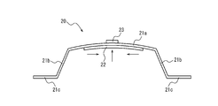
- the actuator 20 may include a frame 21, a piezoelectric element 22, and an action part 23.
- the frame 21 may include a vibration part 21 a, a support part 21 b, and a fixing part 21 c.
- the actuator 20 may be attached to the attachment object 100 at the fixing portion 21 c of the frame 21.
- the actuator 20 may be attached to the vibration target 40 at the action portion 23.
- the actuator 20 may be attached such that the vibration part 21a is along a surface of the vibration object 40 facing the attachment object 100.
- the actuator 20 may be attached to the attachment object 100 and the vibration object 40 by adhesion or the like.
- the vibration part 21a may be a plate-like member having a predetermined thickness.
- the vibration part 21a may be a thin plate having elasticity, for example.
- the vibration part 21a may be made of metal, resin, or a composite material such as metal and resin.
- the vibration part 21a may be a thin metal plate.
- the metal thin plate is also called a shim plate.
- the support part 21b may be located at both ends in the longitudinal direction of the vibration part 21a.
- the support portion 21b may be a thin plate having elasticity, for example, similarly to the vibration portion 21a.
- the support part 21b may be positioned at a predetermined angle with respect to the vibration part 21a.
- the support portion 21b may be positioned at a right angle or a substantially right angle with respect to the vibration portion 21a.
- the support portion 21b may be made of the same material as the vibration portion 21a or may be made of a different material.
- the fixing portion 21 c may have a shape along the surface of the attachment target 100.
- the fixing part 21c may be fixed to the attachment object 100 by, for example, screwing or adhesion.
- the fixed portion 21c may be a thin plate having elasticity, for example, similarly to the vibrating portion 21a.
- the fixed portion 21c may be made of the same material as the vibrating portion 21a or the support portion 21b, or may be made of a different material.
- the vibration part 21a, the support part 21b, and the fixing part 21c may be integrally molded as the frame 21. At least one of the vibration part 21 a, the support part 21 b, and the fixing part 21 c may be molded as a separate body and assembled as the frame 21.
- the frame 21 may be integrally formed by, for example, bending a single metal thin plate by sheet metal processing.
- the frame 21 may be integrally molded by welding the vibration portion 21a, the support portion 21b, and the fixed portion 21c.
- the frame 21 may be made by integral molding of resin.
- the piezoelectric element 22 may be, for example, a rectangular shape having a longitudinal direction.
- the piezoelectric element 22 may be expanded and contracted in various patterns in the longitudinal direction according to an applied voltage signal.
- the piezoelectric element 22 may be a piezoelectric film or a piezoelectric ceramic. Piezoelectric ceramics can generate vibrations with greater vibrational energy than piezoelectric films.
- the piezoelectric element 22 may be replaced with a magnetostrictive element.
- the magnetostrictive element may expand and contract according to the applied magnetic field.
- a magnetostrictive element When a magnetostrictive element is used, a coil or the like that converts an applied voltage signal into a magnetic field may be used together.
- the piezoelectric element 22 may be provided on a surface facing the attachment target 100 of the vibration part 21a.
- the piezoelectric element 22 may be provided so that the longitudinal direction of the piezoelectric element 22 coincides with the longitudinal direction of the vibration part 21a.
- the action part 23 may be provided in the vicinity of the center in the longitudinal direction of the surface of the vibration part 21 a that faces the vibration object 40, and may connect the vibration part 21 a and the vibration object 40.
- the action part 23 may be made of, for example, a rubber material.
- the action part 23 is not limited to a rubber material or the like, and may be composed of another material such as a metal.
- the action part 23 may be joined to the vibration part 21a and the vibration object 40 by bonding or the like, for example.
- the structure in which the piezoelectric element 22 is provided on one surface of the vibration part 21a is also referred to as a unimorph.
- expansion / contraction displacement of the piezoelectric element 22 can cause bending vibration of the vibration part 21a.
- the vibration part 21a can be bent so that the side on which the action part 23 is attached has a convex shape.
- the vibrating portion 21 a can be bent so that the side on which the piezoelectric element 22 is attached has a convex shape.
- the vibration part 21a When both ends of the vibration part 21a are attached to the attachment object 100 by the support part 21b and the fixing part 21c, the vibration part 21a is in the normal direction of the surface on which the piezoelectric element 22 is provided according to the expansion and contraction of the piezoelectric element 22. Can vibrate.
- the direction in which the vibration part 21a vibrates is also referred to as the vibration direction of the vibration part 21a.
- the amplitude of the vibration part 21a can be maximized near the center in the longitudinal direction of the vibration part 21a.
- the displacement of the action part 23 can be close to the maximum.
- the position where the action part 23 is provided is not limited to the vicinity of the center in the longitudinal direction of the vibration part 21a.
- the action part 23 may be provided in a part where the amplitude of the vibration part 21a is maximized.
- the action unit 23 can apply a force generated by the vibration of the vibration unit 21 a to the vibration target 40 and transmit the vibration to the vibration target 40.
- the action part 23 may have a large elastic coefficient in the vibration direction of the vibration part 21a. By doing in this way, the vibration of the vibration part 21a can be efficiently transmitted to the vibration object 40.
- the action part 23 may have a small elastic coefficient in a direction crossing the vibration direction of the vibration part 21a. By doing in this way, the possibility of the damage of the tactile sensation providing apparatus 10 due to an external force can be reduced.
- the elastic coefficient is a constant indicating the relationship between the external force applied to the member and the displacement amount of the member.
- the product of the displacement and the elastic modulus can be an external force. That is, the amount of displacement with respect to the same external force can increase as the elastic coefficient decreases.
- the support portion 21b can maintain a clearance between the vibration portion 21a and the attachment target 100.
- the support portion 21 b can make it difficult for the vibration portion 21 a that vibrates according to the displacement of the piezoelectric element 22 to collide with the attachment target 100.
- the holding member 30 may include a first portion 30a, a second portion 30b, and a third portion 30c.
- the first portion 30a may be attached to the attachment object 100.
- the second portion 30b may be attached to a surface of the vibration target 40 that faces the attachment target 100.
- the third portion 30c may connect the first portion 30a and the second portion 30b.
- the holding member 30 may be a leaf spring having a bent portion, for example. In this case, the first portion 30a and the third portion 30c, or the second portion 30b and the third portion 30c may be separated by a bent portion.
- the holding member 30 shown in FIG. 2 may have two bent portions in the cross-sectional shape. It can be said that the holding member 30 shown in FIG.
- the holding member 30 may be made of, for example, rubber, resin, metal, ceramics, or the like.
- the first portion 30a, the second portion 30b, and the third portion 30c may be integrally configured as the holding member 30.
- the first portion 30 a, the second portion 30 b, and the third portion 30 c may be configured as separate bodies and assembled as the holding member 30.
- the actuator 20 may include not only the piezoelectric element 22 but also an ultrasonic vibrator, a vibration motor, an eccentric motor, or the like.
- the vibration target 40 may have a large mass as compared with the actuator 20 and may have high rigidity.
- the vibration target 40 can be regarded as a rigid body.
- the tactile sensation providing apparatus 10 is more sensitive to a user of a device that touches the vibration target 40 when the vibration target 40 is vibrated as a whole than when the vibration target 40 is vibrated. It can present a tactile sensation efficiently.
- the actuator 20 can displace the vibration target 40 with respect to the attachment target 100 and vibrate the vibration target 40 as a whole. By causing the vibration target 40 to vibrate as a whole, a tactile sensation can be presented to the user of the device touching the vibration target 40.
- the vibration object 40 may be held by the holding member 30 in a region near one end.
- the vibration target 40 may be connected to the attachment target 100 by the actuator 20 on the side opposite to the side held by the holding member 30.
- the vibration target 40 may be displaced with respect to the attachment target 100 on the side to which the actuator 20 is connected.
- the vibration object 40 may hardly be displaced with respect to the attachment object 100 on the side held by the holding member 30.
- the vibration target 40 may be displaced in a direction away from the attachment target 100 due to the vibration of the actuator 20 on the side to which the actuator 20 is connected.
- the vibrating object 40 may hardly be displaced on the side held by the holding member 30.
- the vibration target 40 may rotate about the first fulcrum 32a located between the first portion 30a and the third portion 30c of the holding member 30 as a fulcrum.
- the holding member 30 may have a small elastic coefficient at the first fulcrum 32a.
- the vibration target 40 may rotate with the second fulcrum 32b located between the second portion 30b and the third portion 30c of the holding member 30 as a fulcrum.
- the holding member 30 may have a small elastic coefficient at the second fulcrum 32b.
- the direction in which the vibration target 40 is displaced is not limited to the direction away from the attachment target 100 as illustrated in FIGS. 6 and 7, and may be the direction approaching the attachment target 100.
- the vibration object 40 may be rotated using one of the first fulcrum 32a and the second fulcrum 32b as a fulcrum, or may be rotated using both as a fulcrum. It can be said that the vibration object 40 rotates around the holding member 30 as a fulcrum within a predetermined angle range corresponding to the amplitude of the vibration part 21a of the actuator 20.
- the predetermined angle range can be determined according to the amplitude of the vibration part 21 a and the distance from the fulcrum to the action part 23.
- the actuator 20 can vibrate the vibrating object 40 with a smaller force that moves the entire vibrating object 40 in the translational direction by rotating the vibrating object 40.
- the fulcrum can be said to indicate the point where the cross section intersects with the rotation axis extending in the direction perpendicular to the paper surface. In this case, it can be said that the vibration object 40 rotates about the holding member 30 as a rotation axis.
- the vibration target 40 rotates about the holding member 30 as a fulcrum, it can be said that the force acting on the vibration target 40 from the action portion 23 of the actuator 20 is a torque with respect to the vibration target 40. As the distance between the actuator 20 and the holding member 30 is longer, the torque applied to the vibration target 40 can be increased. By arranging the holding member 30 apart from the actuator 20, the vibration target 40 can be rotated with a smaller force.
- the tactile sensation presentation target 200 can receive greater vibration when touching the vibration target 40 on the side where the actuator 20 is provided than when touching the vibration target 40 on the side where the holding member 30 is provided.
- the tactile sensation providing apparatus 10 can present a greater tactile sensation to the tactile sensation providing object 200 that touches the vibration object 40 on the side where the actuator 20 is provided.
- the vibration object 40 can receive a pressing toward the attachment object 100 when the user operates the operation unit 50.
- the third portion 30c of the holding member 30 can receive a force in the direction in which it is compressed.
- the displacement of the vibrating object 40 can be large. In this case, the strength of the tactile sensation providing apparatus 10 can be reduced. The user may feel uncomfortable due to the displacement of the vibration object 40.
- the third portion 30c of the holding member 30 may have a large elastic coefficient in the direction in which it is compressed. By doing in this way, it becomes difficult for the vibration object 40 to displace toward the attachment object 100 at the time of a user's operation. As a result, the tactile sensation providing apparatus 10 has higher strength with respect to the user's pressing operation, and it is difficult for the user to feel uncomfortable.
- the support portion 21b of the actuator 20 can receive a force in the direction in which it is compressed.
- the support portion 21b may have a large elastic coefficient in the direction in which it is compressed.
- the tactile sensation providing apparatus 10 may further include a controller 60.
- the controller 60 may be configured by a processor or a microcomputer that can execute application software.
- the processor may include a general-purpose processor that reads a specific program and executes a specific function, and a dedicated processor specialized for a specific process.
- a dedicated processor may include an application specific IC.
- the IC for specific applications is also called ASIC (Application Specific Specific Integrated Circuit).
- the processor may include a programmable logic device.
- the programmable logic device is also called PLD (Programmable Logic Device).
- the PLD may include an FPGA (Field-Programmable Gate Array).
- the controller 60 may be one of SoC (System-on-a-Chip) in which one or a plurality of processors cooperate and SiP (System-In-a-Package).
- the controller 60 can also include a storage unit configured by a memory that can store various types of information as necessary.
- the controller 60 may be connected to the actuator 20.
- the controller 60 may output a drive signal to the actuator 20.
- the drive signal may be a voltage signal applied to the piezoelectric element 22 of the actuator 20.
- the drive signal is not limited to a voltage signal, and may be another signal such as a current signal.
- the piezoelectric element 22 may be expanded and contracted in the longitudinal direction according to the drive signal acquired from the controller 60.
- the vibration part 21 a may be bent according to the displacement of the piezoelectric element 22.
- the displacement of the piezoelectric element 22 may be converted into the vibration of the vibration part 21a.
- the drive signal is, for example, a voltage signal
- the piezoelectric element 22 may be configured to expand by applying a positive voltage to the piezoelectric element 22, or the piezoelectric element 22 may be configured to contract.
- the controller 60 can drive the actuator 20 to vibrate the vibration unit 21a.
- the vibration of the vibration part 21 a can be transmitted to the vibration object 40 via the action part 23.
- a tactile sensation can be presented to the user who touched the vibration target 40.
- the controller 60 may be connected to the operation unit 50, for example, as shown in FIG.
- the operation unit 50 can detect that the user of the device is touching the vibration target 40.
- the operation unit 50 may detect that the user of the device is pushing the vibration target 40. In other words, the operation unit 50 may detect whether the pressure on the vibration target 40 is equal to or higher than a predetermined pressure.
- the press against the vibration target 40 may be detected by the actuator 20, for example.
- the pressure on the vibration target 40 may be detected by another sensor provided on the vibration target 40.
- a configuration including the actuator 20 or other sensors that can detect pressure is also referred to as a pressure detection unit.
- the pressure detection unit may output information related to the detected pressure to the operation unit 50.
- the operation unit 50 may output information acquired from the pressure detection unit to the controller 60.
- the operation unit 50 may output information indicating that the pressure applied to the vibration target 40 is equal to or higher than a predetermined pressure to the controller 60.
- the controller 60 may acquire information related to the pressure detected by the pressure detection unit from the pressure detection unit or the operation unit 50 and determine whether the pressure is equal to or higher than a predetermined pressure.
- the controller 60 may output a drive signal to the actuator 20 according to the information acquired from the operation unit 50 or the pressure detection unit, and may vibrate the vibration target 40 when the user is pushing the vibration target 40. By doing so, the tactile sensation providing apparatus 10 can present a tactile sensation to the user who pushed the vibration object 40.
- the operation unit 50 may be provided separately from the vibration target 40.
- the vibration target 40 when the vibration target 40 is a touch panel in which a display panel is combined with the operation unit 50, the vibration target 40 may be dust-proof.
- the vibration object 40 When the vibration object 40 is dust-proof, the dust-proof correspondence does not have to be taken into consideration in the portion where the actuator 20 is attached and in the vicinity thereof. Since no member is attached around the actuator 20, the vibration of the actuator 20 is not easily disturbed. As a result, the vibration generated by the actuator 20 can be increased.
- the tactile sensation providing apparatus 10 can vibrate the vibration target 40 with a relatively small force by rotating the vibration target 40 with the holding member 30 as a fulcrum. By doing so, the vibration generated by the actuator 20 can be efficiently transmitted to the vibration target 40. As a result, the tactile sensation providing apparatus 10 can present a sufficient tactile sensation to the user.
- the tactile sensation providing apparatus 10 may include a holding member 30 as shown in FIG.
- the holding member 30 shown in FIG. 9 may not have a bent portion.
- the holding member 30 may be attached to the attachment object 100 at one end face.
- the holding member 30 may hold the side surface of the vibration target 40 on the other end face side. It can be said that the holding member 30 has a second portion 30 b that holds the vibration target 40 and a third portion 30 c that does not hold the vibration target 40.
- the holding member 30 may be attached to the attachment object 100 at the end face of the third portion 30c.
- the holding member 30 may be configured such that the vibration target 40 can rotate with the portion attached to the attachment target 100 as the first fulcrum 32a.
- the holding member 30 may be configured so that the vibration target 40 can rotate with a boundary portion between the portion that holds the vibration target 40 and the portion that does not hold the second support point 32b.
- the tactile sensation providing apparatus 10 may include a holding member 30 as shown in FIG.
- the holding member 30 shown in FIG. 10 may not have a bent portion.
- the holding member 30 may be attached to the attachment object 100 at one end face.
- the holding member 30 may hold a surface of the vibration target 40 that faces the attachment target 100 on the other end face side.
- the holding member 30 may be configured such that the vibration target 40 can rotate with the portion attached to the attachment target 100 as the first fulcrum 32a.
- the holding member 30 may be configured such that the vibration target 40 can rotate with the portion that holds the vibration target 40 as the second fulcrum 32b.
- the tactile sensation providing apparatus 10 may include a holding member 30 as shown in FIG.
- the holding member 30 shown in FIG. 11 may have one bent portion. It can be said that the holding member 30 shown in FIG. 11 has an L-shaped cross-sectional shape.
- the holding member 30 may have a second portion 30b and a third portion 30c separated by a bent portion.
- the holding member 30 may be attached to the attachment object 100 at the end face of the third portion 30c.
- the holding member 30 may hold the vibration object 40 on the surface facing the attachment object 100 in the second portion 30b.
- the holding member 30 may be configured such that the vibration target 40 can rotate with the portion attached to the attachment target 100 as the first fulcrum 32a.
- the holding member 30 may be configured such that the vibration target 40 can rotate with the bent portion serving as the second fulcrum 32b.
- the tactile sensation providing apparatus 10 may include a holding member 30 as shown in FIG.
- the holding member 30 shown in FIG. 12 may have an H-shaped cross-sectional shape.
- the holding member 30 may include a first portion 30a, a second portion 30b, and a third portion 30c.
- the third portion 30c may be connected to the first portion 30a at one end and to the second portion 30b at the other end.
- the holding member 30 may be attached to the attachment object 100 by the first portion 30a.
- the holding member 30 may hold the vibration target 40 on the surface facing the attachment target 100 by the second portion 30b.
- the holding member 30 may be configured such that the vibration target 40 can rotate with a portion where the first portion 30a and the third portion 30c are connected as the first fulcrum 32a.
- the holding member 30 may be configured such that the vibration target 40 can rotate with the portion where the second portion 30b and the third portion 30c are connected as the second fulcrum 32b.
- descriptions such as “first” and “second” are identifiers for distinguishing the configuration.
- the configurations distinguished by the description of “first” and “second” in the present disclosure can exchange numbers in the configurations.
- the first fulcrum 32a can exchange the identifiers “first” and “second” with the second fulcrum 32b.
- the identifier exchange is performed at the same time.
- the configuration is distinguished even after the identifier is exchanged.
- the identifier may be deleted.
- the configuration from which the identifier is deleted is distinguished by a code. Based on only the description of identifiers such as “first” and “second” in the present disclosure, it should not be used as an interpretation of the order of the configuration, or as a basis for the existence of identifiers with smaller numbers.
Landscapes
- Engineering & Computer Science (AREA)
- General Engineering & Computer Science (AREA)
- Theoretical Computer Science (AREA)
- Human Computer Interaction (AREA)
- Physics & Mathematics (AREA)
- General Physics & Mathematics (AREA)
- User Interface Of Digital Computer (AREA)
Abstract
触感呈示装置は、振動対象を振動させるアクチュエータと、振動対象を保持する保持部材とを備える。保持部材は、アクチュエータと離間して配置される。アクチュエータは、保持部材を支点として、振動対象を回動させる。
Description
本出願は、日本国特許出願2016-230465号(2016年11月28日出願)の優先権を主張するものであり、当該出願の開示全体を、ここに参照のために取り込む。
本開示は、触感呈示装置に関する。
従来、振動を発生させるアクチュエータがタッチセンサ等に配設されている。アクチュエータは、例えばユニモルフ等である。アクチュエータが、タッチセンサ等の振動対象を振動させることにより、振動対象にタッチする利用者に対して触感が呈示される(例えば、特許文献1参照)。
本開示の一実施形態に係る触感呈示装置は、振動対象を振動させるアクチュエータと、振動対象を保持する保持部材とを備える。保持部材は、アクチュエータと離間して配置される。アクチュエータは、保持部材を支点として、振動対象を回動させる。
本開示に係る触感呈示装置10(図1参照)は、種々の機器に設けられてよい。触感呈示装置10は、カーナビゲーションシステム、又は、エアコンディショニングシステム等の車載機器に設けられてよい。触感呈示装置10は、車載機器を操作するスイッチ等とされてよい。触感呈示装置10は、携帯電話、スマートフォン、タブレット型PC(Personal Computer)、ノートPC等に設けられてよい。触感呈示装置10は、これらに限定されるものではなく、デスクトップPC、家電製品、産業用機器若しくはFA(Factory Automation)機器、又は専用端末等、種々の電子機器に設けられてよい。以下の説明で用いられる図は、模式的なものである。図面上の寸法比率等は、現実のものとは必ずしも一致していない。
触感呈示装置10は、利用者に対して十分な触感を呈示するために、振動対象40(図1参照)を大きく振動させる必要がある。振動対象40を大きく振動させるために、アクチュエータ20(図1参照)が発生する振動を大きくしつつ、その振動が振動対象40へ効率よく伝達されることが求められる。
図1、図2及び図3に示されるように、一実施形態に係る触感呈示装置10は、アクチュエータ20と、保持部材30とを備える。アクチュエータ20は、振動対象40と取付対象100との間に位置してよい。保持部材30は、取付対象100に取り付けられ、振動対象40を保持してよい。アクチュエータ20は、振動対象40の一端に近い領域に位置してよい。保持部材30は、アクチュエータ20が位置する側の反対側の一端に近い領域に位置してよい。保持部材30は、アクチュエータ20と離間して配置されてよい。
取付対象100は、例えば、触感呈示装置10が設けられる機器の筐体等であってよい。取付対象100の表面は、平面であると仮定する。取付対象100の表面は、平面に限られず、曲面であってよいし、複数の平面を含んでよい。取付対象100は、一体であってよいし、複数の筐体等の集合であってよい。
振動対象40は、例えば、触感呈示装置10が設けられる機器の操作パネル等であってよい。振動対象40は、LCD(Liquid Crystal Display)又は有機EL(Electro Luminescence)若しくは無機EL等の表示パネルであってよい。振動対象40は、表示パネルにタッチセンサが組み合わされたタッチパネルであってよい。振動対象40は、矩形の板状であると仮定する。振動対象40は、矩形に限られず、多角形、円若しくは楕円、又は、線分若しくは曲線等で囲まれた任意の形状であってよい。振動対象40は、板状に限られず、柱状又はブロック状等の他の形状であってよい。振動対象40は、板状である場合、取付対象100に対向する面と、取付対象100の反対側の面と、側面とを有してよい。
振動対象40は、取付対象100の反対側の面に操作部50を備えてよい。操作部50は、例えばタッチセンサ又はスイッチ等を含んでよい。触感呈示装置10は、アクチュエータ20で振動対象40及び操作部50を振動させることによって、操作部50にタッチする利用者に対して触感を呈示しうる。
図2及び図3に示されるように、アクチュエータ20は、フレーム21と、圧電素子22と、作用部23とを備えてよい。フレーム21は、図4に示されるように、振動部21aと、支持部21bと、固定部21cとを備えてよい。アクチュエータ20は、フレーム21の固定部21cにおいて、取付対象100に取り付けられてよい。アクチュエータ20は、作用部23において、振動対象40に取り付けられてよい。アクチュエータ20は、振動対象40の取付対象100に対向する面に振動部21aが沿うように、取り付けられてよい。アクチュエータ20は、取付対象100及び振動対象40に対して、接着等によって取り付けられてよい。
振動部21aは、所定の厚みを有する板状の部材であってよい。振動部21aは、例えば、弾性を有する薄板であってよい。振動部21aは、金属、樹脂、又は、金属及び樹脂等の複合材料等によって構成されてよい。振動部21aは、金属薄板であってよい。金属薄板は、シム板ともいう。
支持部21bは、振動部21aの長手方向の両端に位置してよい。支持部21bは、振動部21aと同様に、例えば弾性を有する薄板であってよい。支持部21bは、振動部21aに対して所定の角度で位置してよい。支持部21bは、振動部21aに対して、直角又は略直角に位置してよい。支持部21bは、振動部21aと同一の材料で構成されてよいし、異なる材料で構成されてよい。
支持部21bの一方の端部は、振動部21aに接続してよい。支持部21bの他方の端部は、固定部21cに接続してよい。固定部21cは、取付対象100の表面に沿う形状であってよい。固定部21cは、例えば、ねじ止め又は接着等により取付対象100に固定されてよい。固定部21cは、例えば振動部21aと同様に、弾性を有する薄板であってよい。固定部21cは、振動部21a又は支持部21bと同一の材料で構成されてよいし、異なる材料で構成されてよい。
振動部21aと支持部21bと固定部21cとは、フレーム21として一体に成型されてよい。振動部21aと支持部21bと固定部21cとの少なくとも1つは、別体として成型され、フレーム21として組み立てられてよい。フレーム21は、例えば、一枚の金属の薄板を板金加工により折り曲げることによって一体成型されてよい。フレーム21は、振動部21aと支持部21bと固定部21cとがそれぞれ溶接されて一体に成型されてよい。フレーム21は、樹脂の一体成型によって作られてよい。
圧電素子22は、例えば長手方向を有する長方形状等であってよい。圧電素子22は、印加される電圧信号に応じて長手方向に種々のパターンで伸縮変位してよい。圧電素子22は、圧電フィルムであってよいし、圧電セラミックであってよい。圧電セラミックは、圧電フィルムよりも、より大きい振動エネルギーを有する振動を発生させることができる。
圧電素子22は、磁歪素子に置換されてよい。磁歪素子は、印加される磁界に応じて伸縮してよい。磁歪素子が用いられる場合、印加される電圧信号を磁界に変換するコイル等があわせて用いられてよい。
圧電素子22は、振動部21aの取付対象100に対向する面に設けられてよい。圧電素子22は、圧電素子22の長手方向が振動部21aの長手方向と一致するように設けられてよい。
作用部23は、振動部21aの振動対象40に対向する面の長手方向の中央付近に設けられ、振動部21aと振動対象40とを接続してよい。作用部23は、例えばゴム材料等で構成されてよい。作用部23は、ゴム材料等に限られず、金属等の他の材料で構成されてよい。作用部23は、例えば接着等によって振動部21a及び振動対象40に接合されてよい。
振動部21aの一方の面に圧電素子22が設けられた構造は、ユニモルフともいう。ユニモルフにおいては、圧電素子22の伸縮変位が、振動部21aの屈曲振動を引き起こしうる。例えば図5に示されるように圧電素子22が縮む場合、振動部21aは、作用部23が取り付けられている側が凸形状となるように屈曲しうる。図5に示される場合とは逆に圧電素子22が伸びる場合、振動部21aは、圧電素子22が取り付けられている側が凸形状となるように屈曲しうる。振動部21aの両端が支持部21b及び固定部21cによって取付対象100に取り付けられている場合、振動部21aは、圧電素子22の伸縮に応じて、圧電素子22が設けられる面の法線方向に振動しうる。振動部21aが振動する方向は、振動部21aの振動方向ともいう。振動部21aの振幅は、振動部21aの長手方向の中央付近において最大になりうる。
振動部21aの振幅が長手方向の中央付近において最大となる場合、作用部23の変位は、最大に近くなりうる。作用部23が設けられる位置は振動部21aの長手方向の中央付近に限られない。作用部23は、振動部21aの振幅が最大となる部分に設けられてよい。作用部23は、振動部21aの振動による力を振動対象40に作用させ、振動を振動対象40に伝達しうる。
作用部23は、振動部21aの振動方向に大きい弾性係数を有してよい。このようにすることで、振動部21aの振動が振動対象40に効率よく伝達されうる。作用部23は、振動部21aの振動方向に交差する方向に小さい弾性係数を有してよい。このようにすることで、外力による触感呈示装置10の破損の可能性が低減されうる。弾性係数は、部材にかかる外力と部材の変位量との関係を示す定数である。変位量と弾性係数との積が外力となりうる。つまり同じ外力に対する変位量は、弾性係数が小さいほど大きくなりうる。
支持部21bは、振動部21aと取付対象100との間のクリアランスを保ちうる。支持部21bは、圧電素子22の変位に応じて振動する振動部21aを取付対象100に衝突しにくくしうる。
図2に示されるように、保持部材30は、第1部分30aと、第2部分30bと、第3部分30cとを有してよい。第1部分30aは、取付対象100に取り付けられてよい。第2部分30bは、振動対象40の取付対象100に対向する面に取り付けられてよい。第3部分30cは、第1部分30aと第2部分30bとを接続してよい。保持部材30は、例えば、屈曲部分を有する板ばねであってよい。この場合、第1部分30aと第3部分30c、又は、第2部分30bと第3部分30cとは、屈曲部分で区切られてよい。図2に示される保持部材30は、断面形状において2箇所の屈曲部分を有してよい。図2に示される保持部材30は、コの字状又はU字状の断面形状を有するともいえる。保持部材30は、例えば、ゴム、樹脂、金属、又はセラミックス等で構成されてよい。第1部分30aと第2部分30bと第3部分30cとは、保持部材30として一体に構成されてよい。第1部分30aと第2部分30bと第3部分30cとは、別体として構成され、保持部材30として組み立てられてよい。
アクチュエータ20は、圧電素子22を含んで構成されるだけでなく、超音波振動子又は振動モータ若しくは偏心モータ等を含んで構成されてよい。
振動対象40は、アクチュエータ20と比較して大きい質量を有し、高い剛性を有してよい。振動対象40は、剛体とみなされうる。振動対象40が剛体とみなされる場合、触感呈示装置10は、振動対象40を屈曲振動させる場合より、振動対象40を全体として振動させる場合において、振動対象40にタッチした機器の利用者に対して効率的に触感を呈示しうる。取付対象100が固定されていると仮定した場合、アクチュエータ20は、取付対象100に対して振動対象40を変位させ、振動対象40を全体として振動させうる。振動対象40を全体として振動させることで、振動対象40にタッチした機器の利用者に対して触感が呈示されうる。
図1及び図2に示されるように、振動対象40は、一方の端部に近い領域において、保持部材30によって保持されてよい。振動対象40は、保持部材30によって保持される側の反対側において、アクチュエータ20によって、取付対象100と接続されてよい。アクチュエータ20が駆動されて、振動を発生する場合、振動対象40は、アクチュエータ20が接続される側において、取付対象100に対して変位してよい。振動対象40は、保持部材30によって保持される側において、取付対象100に対してほとんど変位しなくてよい。
例えば図6及び図7に示されるように、振動対象40は、アクチュエータ20が接続される側において、アクチュエータ20の振動によって、取付対象100から離れる方向に変位してよい。一方で、振動対象40は、保持部材30によって保持される側において、ほとんど変位しなくてよい。
図6に示される場合において、振動対象40は、保持部材30の第1部分30aと第3部分30cとの間に位置する第1支点32aを支点として回動してよい。この場合、保持部材30は、第1支点32aにおいて、小さい弾性係数を有してよい。図7に示される場合において、振動対象40は、保持部材30の第2部分30bと第3部分30cとの間に位置する第2支点32bを支点として回動してよい。この場合、保持部材30は、第2支点32bにおいて、小さい弾性係数を有してよい。
振動対象40が変位する方向は、図6及び図7に例示されるように、取付対象100から離れる方向に限られず、取付対象100に近づく方向であってよい。
振動対象40は、第1支点32a及び第2支点32bの一方を支点として回動してよいし、両方を支点として回動してよい。振動対象40は、アクチュエータ20の振動部21aの振幅に応じた所定の角度範囲内で保持部材30を支点として回動するといえる。所定の角度範囲は、振動部21aの振幅の大きさ、及び、支点から作用部23までの距離に応じて定められうる。アクチュエータ20は、振動対象40を回動させることによって、振動対象40全体を並進方向に移動させるより小さい力で振動対象40を振動させうる。
図6及び図7に示される断面において、支点は、紙面に垂直な方向に延在する回転軸と断面とが交差する点を示しているともいえる。この場合、振動対象40は、保持部材30を回転軸として回動するともいえる。
振動対象40が保持部材30を支点として回動する場合、アクチュエータ20の作用部23から振動対象40に作用する力は、振動対象40に対するトルクであるともいえる。アクチュエータ20と保持部材30との間の距離が長いほど、振動対象40に与えられるトルクは大きくなりうる。保持部材30がアクチュエータ20から離間して配置されることによって、振動対象40は、より小さい力で回動されうる。
触感呈示対象200は、アクチュエータ20が設けられる側で振動対象40にタッチする場合、保持部材30が設けられる側で振動対象40にタッチする場合より、大きい振動を受けうる。触感呈示装置10は、アクチュエータ20が設けられる側で振動対象40にタッチする触感呈示対象200に対して、より大きい触感を呈示しうる。
振動対象40は、利用者が操作部50を操作することによって、取付対象100に向かう押圧を受けうる。振動対象40が押圧を受ける場合、保持部材30の第3部分30cは、圧縮される方向の力を受けうる。第3部分30cが小さい弾性係数を有する場合、振動対象40の変位が大きくなりうる。この場合、触感呈示装置10の強度が低くなりうる。利用者は、振動対象40の変位によって違和感を受けることがある。
保持部材30の第3部分30cは、圧縮される方向に大きい弾性係数を有してよい。このようにすることで、利用者の操作時に振動対象40が取付対象100に向かって変位しにくくなる。結果として、触感呈示装置10は、利用者の押下操作に対してより高い強度を有し、利用者に違和感を与えにくくなる。
振動対象40が押圧を受ける場合、アクチュエータ20の支持部21bは、圧縮される方向の力を受けうる。支持部21bは、圧縮される方向に大きい弾性係数を有してよい。このようにすることで、利用者の操作時に振動対象40が取付対象100に向かって変位しにくくなる。結果として、触感呈示装置10は、利用者の押下操作に対してより高い強度を有し、利用者に違和感を与えにくくなる。
図8に示されるように、一実施形態に係る触感呈示装置10は、コントローラ60をさらに備えてよい。コントローラ60は、アプリケーションソフトウェアを実行可能なプロセッサまたはマイクロコンピュータ等により構成されてよい。プロセッサは、特定のプログラムを読み込ませて特定の機能を実行する汎用のプロセッサ、及び特定の処理に特化した専用のプロセッサを含んでよい。専用のプロセッサは、特定用途向けICを含んでよい。特定用途向けICは、ASIC(Application Specific Integrated Circuit)ともいう。プロセッサは、プログラマブルロジックデバイスを含んでよい。プログラマブルロジックデバイスは、PLD(Programmable Logic Device)ともいう。PLDは、FPGA(Field-Programmable Gate Array)を含んでよい。コントローラ60は、1つ又は複数のプロセッサが協働するSoC(System-on-a-Chip)、及びSiP(System In a Package)のいずれかであってよい。コントローラ60は、必要に応じて各種情報を記憶することができるメモリ等によって構成される記憶部等も適宜含みうる。
コントローラ60は、アクチュエータ20に接続されてよい。コントローラ60は、アクチュエータ20に駆動信号を出力してよい。駆動信号は、アクチュエータ20の圧電素子22に対して印加される電圧信号であってよい。駆動信号は、電圧信号に限られず、電流信号等の他の信号であってよい。
圧電素子22は、コントローラ60から取得した駆動信号に応じて、長手方向に伸縮変位してよい。振動部21aは、圧電素子22の変位に応じて屈曲してよい。圧電素子22の変位は、振動部21aの振動に変換されてよい。駆動信号が例えば電圧信号である場合、圧電素子22に正の電圧が印加されることによって、圧電素子22が伸びるように構成されてよいし、圧電素子22が縮むように構成されてよい。
以上のようにして、コントローラ60は、アクチュエータ20を駆動し、振動部21aを振動させうる。振動部21aの振動は、作用部23を介して振動対象40に伝達されうる。振動対象40に振動が伝達されることによって、振動対象40にタッチした利用者に対して触感が呈示されうる。
コントローラ60は、例えば図8に示されるように、操作部50に接続されてよい。操作部50は、機器の利用者が振動対象40にタッチしていることを検出しうる。操作部50は、機器の利用者が振動対象40をプッシュしていることを検出してよい。言い換えれば、操作部50は、振動対象40に対する押圧が所定圧力以上であるか検出してよい。振動対象40に対する押圧は、例えばアクチュエータ20によって検出されてよい。振動対象40に対する押圧は、振動対象40に設けられる他のセンサによって検出されてよい。アクチュエータ20又は他のセンサ等を含む、押圧を検出しうる構成は、押圧検出部ともいう。押圧検出部は、検出した押圧に係る情報を操作部50に出力してよい。操作部50は、押圧検出部から取得した情報を、コントローラ60に出力してよい。操作部50は、振動対象40に対して加えられる押圧が所定圧力以上であることを示す情報をコントローラ60に出力してよい。コントローラ60は、押圧検出部又は操作部50から、押圧検出部が検出した押圧に係る情報を取得し、押圧が所定圧力以上であるか判定してよい。コントローラ60は、操作部50又は押圧検出部から取得した情報に応じて、アクチュエータ20に駆動信号を出力し、利用者が振動対象40をプッシュしているときに振動対象40を振動させてよい。このようにすることで、触感呈示装置10は、振動対象40をプッシュした利用者に対して触感を呈示することができる。操作部50は、振動対象40とは別体として設けられてよい。
本実施形態において、例えば振動対象40が操作部50に表示パネルが組み合わされたタッチパネルである場合、振動対象40は、防塵対応されていることがある。振動対象40が防塵対応されている場合、アクチュエータ20が取り付けられる部分、及び、その周辺において防塵対応は考慮されなくてよい。アクチュエータ20の周囲に部材が取り付けられないことによって、アクチュエータ20の振動は、妨げられにくくなる。結果として、アクチュエータ20が発生する振動が大きくされうる。
本実施形態に係る触感呈示装置10は、保持部材30を支点として振動対象40を回動させることによって、比較的小さい力で振動対象40を振動させうる。このようにすることで、アクチュエータ20が発生する振動が、振動対象40へ効率よく伝達されうる。結果として、触感呈示装置10は、利用者に対して十分な触感を呈示しうる。
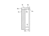
他の実施形態に係る触感呈示装置10は、図9に示されるような保持部材30を備えてよい。図9に示される保持部材30は、屈曲部分を有しなくてよい。保持部材30は、一方の端面において取付対象100に取り付けられてよい。保持部材30は、他方の端面の側において、振動対象40の側面を保持してよい。保持部材30は、振動対象40を保持する第2部分30bと、振動対象40を保持しない第3部分30cとを有するともいえる。この場合、保持部材30は、第3部分30cの端面において取付対象100に取り付けられてよい。保持部材30は、取付対象100に取り付けられる部分を第1支点32aとして、振動対象40が回動できるように構成されてよい。保持部材30は、振動対象40を保持する部分と、保持しない部分との境界部分を第2支点32bとして、振動対象40が回動できるように構成されてよい。
他の実施形態に係る触感呈示装置10は、図10に示されるような保持部材30を備えてよい。図10に示される保持部材30は、屈曲部分を有しなくてよい。保持部材30は、一方の端面において取付対象100に取り付けられてよい。保持部材30は、他方の端面の側において、振動対象40の取付対象100に対向する面を保持してよい。保持部材30は、取付対象100に取り付けられる部分を第1支点32aとして、振動対象40が回動できるように構成されてよい。保持部材30は、振動対象40を保持する部分を第2支点32bとして、振動対象40が回動できるように構成されてよい。
他の実施形態に係る触感呈示装置10は、図11に示されるような保持部材30を備えてよい。図11に示される保持部材30は、1箇所の屈曲部分を有してよい。図11に示される保持部材30は、L字状の断面形状を有するともいえる。保持部材30は、屈曲部分で区切られる第2部分30bと第3部分30cとを有してよい。保持部材30は、第3部分30cの端面において取付対象100に取り付けられてよい。保持部材30は、第2部分30bにおいて振動対象40を取付対象100に対向する面で保持してよい。保持部材30は、取付対象100に取り付けられる部分を第1支点32aとして、振動対象40が回動できるように構成されてよい。保持部材30は、屈曲部分を第2支点32bとして、振動対象40が回動できるように構成されてよい。
他の実施形態に係る触感呈示装置10は、図12に示されるような保持部材30を備えてよい。図12に示される保持部材30は、H字状の断面形状を有してよい。保持部材30は、第1部分30aと、第2部分30bと、第3部分30cとを有してよい。第3部分30cは、一端で第1部分30aと接続し、他の一端で第2部分30bと接続してよい。保持部材30は、第1部分30aで取付対象100に取り付けられてよい。保持部材30は、第2部分30bによって振動対象40を取付対象100に対向する面で保持してよい。保持部材30は、第1部分30aと第3部分30cとが接続する部分を第1支点32aとして、振動対象40が回動できるように構成されてよい。保持部材30は、第2部分30bと第3部分30cとが接続する部分を第2支点32bとして、振動対象40が回動できるように構成されてよい。
本開示に係る実施形態について諸図面及び実施例に基づき説明してきたが、当業者であれば本開示に基づき種々の変形又は修正を行うことが容易であることに注意されたい。従って、これらの変形又は修正は本開示の範囲に含まれることに留意されたい。
本開示において「第1」及び「第2」等の記載は、当該構成を区別するための識別子である。本開示における「第1」及び「第2」等の記載で区別された構成は、当該構成における番号を交換することができる。例えば、第1支点32aは、第2支点32bと識別子である「第1」と「第2」とを交換することができる。識別子の交換は同時に行われる。識別子の交換後も当該構成は区別される。識別子は削除してよい。識別子を削除した構成は、符号で区別される。本開示における「第1」及び「第2」等の識別子の記載のみに基づいて、当該構成の順序の解釈、小さい番号の識別子が存在することの根拠に利用してはならない。
10 触感呈示装置
20 アクチュエータ
21 フレーム
21a 振動部
21b 支持部
21c 固定部
22 圧電素子
23 作用部
30 保持部材
30a、30b、30c 第1部分、第2部分、第3部分
32a、32b 第1支点、第2支点
40 振動対象
50 操作部
60 コントローラ
100 取付対象
200 触感呈示対象
20 アクチュエータ
21 フレーム
21a 振動部
21b 支持部
21c 固定部
22 圧電素子
23 作用部
30 保持部材
30a、30b、30c 第1部分、第2部分、第3部分
32a、32b 第1支点、第2支点
40 振動対象
50 操作部
60 コントローラ
100 取付対象
200 触感呈示対象
Claims (2)
- 振動対象を振動させるアクチュエータと、
前記振動対象を保持する保持部材と、
を備え、
前記保持部材は、前記アクチュエータと離間して配置され、
前記アクチュエータは、前記保持部材を支点として、前記振動対象を回動させる、
触感呈示装置。 - 前記アクチュエータは、前記振動対象を所定の角度範囲内で回動させる、請求項1に記載の触感呈示装置。
Priority Applications (2)
| Application Number | Priority Date | Filing Date | Title |
|---|---|---|---|
| US16/464,644 US10969868B2 (en) | 2016-11-28 | 2017-11-10 | Tactile sensation providing apparatus |
| EP17873994.2A EP3547078B1 (en) | 2016-11-28 | 2017-11-10 | Tactile sensation presentation device |
Applications Claiming Priority (2)
| Application Number | Priority Date | Filing Date | Title |
|---|---|---|---|
| JP2016230465A JP6855222B2 (ja) | 2016-11-28 | 2016-11-28 | 触感呈示装置 |
| JP2016-230465 | 2016-11-28 |
Publications (1)
| Publication Number | Publication Date |
|---|---|
| WO2018096956A1 true WO2018096956A1 (ja) | 2018-05-31 |
Family
ID=62195196
Family Applications (1)
| Application Number | Title | Priority Date | Filing Date |
|---|---|---|---|
| PCT/JP2017/040625 Ceased WO2018096956A1 (ja) | 2016-11-28 | 2017-11-10 | 触感呈示装置 |
Country Status (4)
| Country | Link |
|---|---|
| US (1) | US10969868B2 (ja) |
| EP (1) | EP3547078B1 (ja) |
| JP (1) | JP6855222B2 (ja) |
| WO (1) | WO2018096956A1 (ja) |
Families Citing this family (4)
| Publication number | Priority date | Publication date | Assignee | Title |
|---|---|---|---|---|
| WO2018123661A1 (ja) * | 2016-12-27 | 2018-07-05 | 日本電産コパル株式会社 | 触覚フィードバック装置及び該触覚フィードバック装置を備えた電子機器 |
| JP6528014B1 (ja) * | 2019-02-27 | 2019-06-12 | カルソニックカンセイ株式会社 | 触感発生装置および触感発生方法 |
| WO2022252058A1 (zh) * | 2021-05-31 | 2022-12-08 | 京东方科技集团股份有限公司 | 显示装置 |
| KR20250100252A (ko) * | 2023-12-26 | 2025-07-03 | 엘지디스플레이 주식회사 | 진동 장치와, 이를 포함하는 표시 장치 및 운송 장치 |
Citations (4)
| Publication number | Priority date | Publication date | Assignee | Title |
|---|---|---|---|---|
| JP2013080327A (ja) * | 2011-10-03 | 2013-05-02 | Sony Corp | 力覚提示装置 |
| JP2013225173A (ja) * | 2012-04-19 | 2013-10-31 | Toyota Motor Corp | デザイン形状提示装置およびデザイン形状提示システム |
| JP5452729B2 (ja) | 2010-10-21 | 2014-03-26 | 京セラ株式会社 | タッチパネル装置 |
| JP2016095549A (ja) * | 2014-11-12 | 2016-05-26 | 京セラ株式会社 | 触感呈示装置 |
Family Cites Families (8)
| Publication number | Priority date | Publication date | Assignee | Title |
|---|---|---|---|---|
| JPH0824788A (ja) * | 1994-07-11 | 1996-01-30 | Toshiba Corp | 加振アクチュエータ |
| US6256011B1 (en) * | 1997-12-03 | 2001-07-03 | Immersion Corporation | Multi-function control device with force feedback |
| US7561142B2 (en) * | 1999-07-01 | 2009-07-14 | Immersion Corporation | Vibrotactile haptic feedback devices |
| US7456821B2 (en) * | 2004-11-30 | 2008-11-25 | Immersion Corporation | User interface device |
| JPWO2011074579A1 (ja) * | 2009-12-15 | 2013-04-25 | 日本電気株式会社 | アクチュエータ、圧電アクチュエータ、電子機器、並びに振動減衰及び振動方向変換方法 |
| WO2016075935A1 (ja) | 2014-11-12 | 2016-05-19 | 京セラ株式会社 | 触感呈示装置 |
| JP6086960B2 (ja) * | 2015-08-20 | 2017-03-01 | Necトーキン株式会社 | 入力装置 |
| US10384123B2 (en) * | 2017-06-01 | 2019-08-20 | Microsoft Technology Licensing, Llc | Motor-driven adjustable-tension trigger |
-
2016
- 2016-11-28 JP JP2016230465A patent/JP6855222B2/ja active Active
-
2017
- 2017-11-10 US US16/464,644 patent/US10969868B2/en active Active
- 2017-11-10 WO PCT/JP2017/040625 patent/WO2018096956A1/ja not_active Ceased
- 2017-11-10 EP EP17873994.2A patent/EP3547078B1/en active Active
Patent Citations (4)
| Publication number | Priority date | Publication date | Assignee | Title |
|---|---|---|---|---|
| JP5452729B2 (ja) | 2010-10-21 | 2014-03-26 | 京セラ株式会社 | タッチパネル装置 |
| JP2013080327A (ja) * | 2011-10-03 | 2013-05-02 | Sony Corp | 力覚提示装置 |
| JP2013225173A (ja) * | 2012-04-19 | 2013-10-31 | Toyota Motor Corp | デザイン形状提示装置およびデザイン形状提示システム |
| JP2016095549A (ja) * | 2014-11-12 | 2016-05-26 | 京セラ株式会社 | 触感呈示装置 |
Non-Patent Citations (1)
| Title |
|---|
| See also references of EP3547078A4 |
Also Published As
| Publication number | Publication date |
|---|---|
| US10969868B2 (en) | 2021-04-06 |
| EP3547078A4 (en) | 2020-07-22 |
| US20190377414A1 (en) | 2019-12-12 |
| EP3547078A1 (en) | 2019-10-02 |
| JP6855222B2 (ja) | 2021-04-07 |
| EP3547078B1 (en) | 2022-07-20 |
| JP2018088089A (ja) | 2018-06-07 |
Similar Documents
| Publication | Publication Date | Title |
|---|---|---|
| US11411167B2 (en) | Actuator and tactile sensation providing apparatus | |
| US11527704B2 (en) | Actuator and tactile sensation providing apparatus | |
| WO2018096956A1 (ja) | 触感呈示装置 | |
| US11877515B2 (en) | Actuator and tactile sensation providing apparatus | |
| JP6626755B2 (ja) | アクチュエータ及び触感呈示装置 | |
| WO2015146116A1 (ja) | 振動モジュール及び電子機器 | |
| JP7162508B2 (ja) | アクチュエータ及び触感呈示装置 | |
| JP6811297B2 (ja) | 触感呈示装置 | |
| JP6926029B2 (ja) | 構造体及び触感呈示装置 | |
| KR102216082B1 (ko) | 유닛 및 촉감 제시 장치 | |
| CN213601183U (zh) | 振动构造 |
Legal Events
| Date | Code | Title | Description |
|---|---|---|---|
| 121 | Ep: the epo has been informed by wipo that ep was designated in this application |
Ref document number: 17873994 Country of ref document: EP Kind code of ref document: A1 |
|
| NENP | Non-entry into the national phase |
Ref country code: DE |
|
| WWE | Wipo information: entry into national phase |
Ref document number: 2017873994 Country of ref document: EP |