WO2018097002A1 - ストラップおよびストラップを備えたバッグ - Google Patents
ストラップおよびストラップを備えたバッグ Download PDFInfo
- Publication number
- WO2018097002A1 WO2018097002A1 PCT/JP2017/041071 JP2017041071W WO2018097002A1 WO 2018097002 A1 WO2018097002 A1 WO 2018097002A1 JP 2017041071 W JP2017041071 W JP 2017041071W WO 2018097002 A1 WO2018097002 A1 WO 2018097002A1
- Authority
- WO
- WIPO (PCT)
- Prior art keywords
- handle
- strap
- bag
- shoulder
- locking portion
- Prior art date
- Legal status (The legal status is an assumption and is not a legal conclusion. Google has not performed a legal analysis and makes no representation as to the accuracy of the status listed.)
- Ceased
Links
Images





Classifications
-
- A—HUMAN NECESSITIES
- A45—HAND OR TRAVELLING ARTICLES
- A45C—PURSES; LUGGAGE; HAND CARRIED BAGS
- A45C13/00—Details; Accessories
- A45C13/30—Straps; Bands
-
- A—HUMAN NECESSITIES
- A45—HAND OR TRAVELLING ARTICLES
- A45C—PURSES; LUGGAGE; HAND CARRIED BAGS
- A45C3/00—Flexible luggage; Handbags
-
- A—HUMAN NECESSITIES
- A45—HAND OR TRAVELLING ARTICLES
- A45F—TRAVELLING OR CAMP EQUIPMENT: SACKS OR PACKS CARRIED ON THE BODY
- A45F3/00—Travelling or camp articles; Sacks or packs carried on the body
- A45F3/02—Sacks or packs carried on the body by means of one strap passing over the shoulder
-
- A—HUMAN NECESSITIES
- A45—HAND OR TRAVELLING ARTICLES
- A45F—TRAVELLING OR CAMP EQUIPMENT: SACKS OR PACKS CARRIED ON THE BODY
- A45F3/00—Travelling or camp articles; Sacks or packs carried on the body
- A45F3/14—Carrying-straps; Pack-carrying harnesses
-
- A—HUMAN NECESSITIES
- A45—HAND OR TRAVELLING ARTICLES
- A45F—TRAVELLING OR CAMP EQUIPMENT: SACKS OR PACKS CARRIED ON THE BODY
- A45F3/00—Travelling or camp articles; Sacks or packs carried on the body
- A45F3/02—Sacks or packs carried on the body by means of one strap passing over the shoulder
- A45F2003/025—Sacks or packs carried on the body by means of one strap passing over the shoulder and one additional strap around the waist
-
- A—HUMAN NECESSITIES
- A45—HAND OR TRAVELLING ARTICLES
- A45F—TRAVELLING OR CAMP EQUIPMENT: SACKS OR PACKS CARRIED ON THE BODY
- A45F3/00—Travelling or camp articles; Sacks or packs carried on the body
- A45F3/14—Carrying-straps; Pack-carrying harnesses
- A45F2003/142—Carrying-straps
-
- A—HUMAN NECESSITIES
- A45—HAND OR TRAVELLING ARTICLES
- A45F—TRAVELLING OR CAMP EQUIPMENT: SACKS OR PACKS CARRIED ON THE BODY
- A45F3/00—Travelling or camp articles; Sacks or packs carried on the body
- A45F3/14—Carrying-straps; Pack-carrying harnesses
- A45F2003/144—Pack-carrying waist or torso belts
Definitions
- the present invention relates to a bag strap having a handle that can be hung on a shoulder.
- a bag with a handle that can be hung on the shoulder may fall off the shoulder when the handle is put on the shoulder.
- the applicant of the present invention has proposed a bag having a structure in which a handle and a bottom portion of the bag are connected by a strap (for example, Patent Document 1 or Patent Document 2).
- an object of the present invention is to provide a strap that prevents the handle from slipping off the shoulder without impeding convenience, and a bag provided with this strap.
- a bag handle on the shoulder may be hooked on the handle from the front and back sides of the user through the armpit on the opposite side of the handle. It is possible.
- this strap it is possible to make it difficult for the handle on the shoulder to slip off without arranging a bag on the back side of the user.
- This strap is also A first locking portion provided at at least one end;
- the second locking portion is provided at a position different from the first locking portion, and can be locked to the first locking portion, It may be possible to hook the handle by passing the handle inside a ring formed by locking the first locking portion and the second locking portion.
- This strap can be easily attached to and detached from the handle.
- This strap is also The first locking portion and the second locking portion are Different surfaces of the strap may be locked face to face.
- This strap can enhance the effect of preventing the handle from slipping off the shoulder.
- This strap is also At least one end portion has a flange portion that is open between the tip and the shaft, The buttocks It may be one that can be hooked on the handle.
- This strap can be easily attached to and detached from the handle.
- the first bag of the present invention that solves the above-mentioned object is: A handle that can be hung on the shoulder, A first connection part and a second connection part provided on the handle; In the state where the handle is hung on the shoulder, the first connection portion and the second connection portion are respectively passed from the front side and the back side of the user through the armpit opposite to the side where the handle is located. And a connectable strap.
- the second bag of the present invention that solves the above-mentioned object is A handle that can be hung on the shoulder, A connection provided on the handle; In the state where the handle is hung on the shoulder, it can be connected to the connection portion from either the front side or the back side of the user through the armpit opposite to the side where the handle is located. And a strap that can be hooked to the handle from the other side different from the one side.
- the third bag of the present invention that solves the above-mentioned object is A handle that can be hung on the shoulder, A connection provided on the handle; A strap having one end fixed to the handle; The strap is In the state where the handle is hung on the shoulder, the handle can be connected to the connection portion from either the front side or the back side of the user through the armpit opposite to the side where the handle is located. It is characterized by being.
- the 4th bag of this invention which solves the said objective is A handle that can be hung on the shoulder, A strap having one end fixed to the handle; The strap is In the state where the handle is hung on the shoulder, it can be hooked on the handle from either the front side or the back side of the user through the armpit opposite to the side where the handle is located It is characterized by being.
- the contents of the bag can be confirmed while the handle is hung on the shoulder, but the handle can be prevented from slipping off the shoulder.
- the second bag and the fourth bag are The strap is A first locking portion provided at an end on the side hooked to the handle;
- the second locking portion is provided at a position different from the first locking portion, and can be locked to the first locking portion, It may be possible to hook the handle by passing the handle inside a ring formed by locking the first locking portion and the second locking portion.
- This bag can be easily attached to and detached from the strap handle.
- the second bag and the fourth bag are The first locking portion and the second locking portion are Different surfaces of the strap may be locked face to face.
- This bag can enhance the effect of making it difficult for the handle to slip off the shoulder.
- the second bag and the fourth bag are The strap is At the end on the side to be hooked on the handle, it has a collar part that is open between the tip and the shaft, The buttocks It may be one that can be hooked on the handle.
- This bag can be easily attached to and detached from the strap handle.
- the fifth bag of the present invention that solves the above-mentioned object is A handle that can be hung on the shoulder, A first connection part and a second connection part provided at the bottom; In the state where the handle is hung on the shoulder, it is connected to the first connection part and the second connection part from the front side and the back side of the user by turning around the body part opposite to the side where the bottom part is located. And a possible strap.
- the contents of the bag can be confirmed while the handle is hung on the shoulder, but the handle can be prevented from slipping off the shoulder.
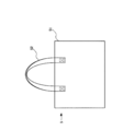
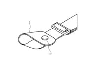
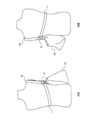
- FIG. 1 It is a figure which shows one Embodiment of the strap of this invention. It is a front view which shows an example of the bag to which the strap shown in FIG. 1 is attached. It is a side view which shows the bag of FIG. It is a figure which shows a mode that the strap shown in FIG. 1 is used. It is a figure which shows an example of the edge part of a strap. It is a figure which shows an example of the use condition at the time of employ
- FIG. 1 is a view showing an embodiment of the strap of the present invention.
- the strap 1 of the embodiment shown in FIG. 1 corresponds to an example of the strap of the present invention.
- the strap 1 is provided with the recesses 21 and 31 and the protrusions 22 and 32 of the snap button at intervals between the end portions 2 and 3, respectively.
- the end portions 2 and 3 can be formed into a ring by fastening the concave portions 21 and 31 and the convex portions 22 and 32.
- the strap 1 is provided with a length adjusting member 4, and the length of the strap 1 can be adjusted by changing the position of the length adjusting member 4.
- FIG. 2 is a front view showing an example of a bag to which the strap 1 shown in FIG. 1 is attached.
- FIG. 3 is a side view showing the bag of FIG.
- FIG. 4 is a diagram showing a state in which the strap 1 shown in FIG. 1 is used. In FIG. 4, the length adjusting member 4 is omitted.
- the bag 5 shown in FIGS. 2 and 3 has a handle 52 attached to a shoulder of the bag main body 51 and is called a so-called tote bag. As shown in FIG. 3, the handle 52 is attached to each of the front side and the back side of the bag body 51.
- the strap 1 shown in FIG. 1 is used for the bag 5 with the handle 52 on the shoulder. Specifically, the both ends 2 and 3 are respectively wound around the handle 52 from the front side and the back side of the user through the armpit opposite to the side where the handle 52 is located. At this time, both end portions 2 and 3 of the strap 1 form a ring by fastening the concave portions 21 and 31 and the convex portions 22 and 32, and the handle 52 passes through the inside thereof. Yes.
- This state is also a state in which the rings of the end portions 2 and 3 of the strap 1 are hooked on the handle 52.
- the handle 52 is hung on the left shoulder. However, the handle 52 can be used in the same manner even when it is hung on the right shoulder.
- the length of the strap 1 is adjusted using the length adjusting member 4 to fit the strap 1 to the user.
- the force that the strap 1 pulls the handle 52 becomes stronger, and the handle 52 is bent. In this case, the handle 52 can be prevented from slipping off from the shoulder.
- the length of the strap 1 can be adjusted so that the strap 1 fits the user's body. That's fine.
- the strap 1 restricts this movement, and the handle 52 can be prevented from slipping off the shoulder. it can.
- the position of the bag 5 is mainly on the side of the user and can be moved back and forth somewhat. For example, by shifting the bag 5 to the front of the user, the user can confirm the contents of the bag and can be prevented from being annoying in a crowded train. Further, for example, if the strap 1 is hooked on the handle 52 on the user side, the contents of the bag 5 can be easily confirmed. Thus, since the strap 1 described above does not require a change in the position of the bag 5 in use, it can be used without impeding the convenience of the bag 5.
- the strap 1 does not require a special configuration as long as it can be hung from the shoulder, and does not limit the design of the bag itself. That is, a bag having a handle that can be worn on the shoulder can be used regardless of the design.
- the handle may be a single bag.
- the structure which hooks the strap 1 on the handle 52 it is not limited to a snap button.
- it can be easily attached to and detached from the handle 52.
- this strap 1 is used when riding a bicycle, the handle of the bag can be prevented from slipping off the shoulder, and after getting off the bicycle, the strap 1 is removed and only the bag is used. Therefore, the usage of the bag can be expanded.
- the strap 1 of the embodiment described above is an example, and other configurations that can be adopted will be described.
- the present invention is not limited to this snap button.
- the structure which provided the combination of the possible hole may be sufficient. That is, any combination that can be locked and that can form a ring that can be passed through the handle in the locked state. This combination corresponds to an example of the first locking portion and the second locking portion of the present invention.
- another member serving as a stopper may be provided so that the ring does not come off or the ring is maintained even if it is removed.
- the strap 1 shown in FIG. 1 merely restricts the movement of the handle 52, and even if it is removed, the bag 5 does not fall immediately. Further, in view of the appearance of the bag 5, there is a possibility that the use of the strap 1 will be avoided. For these reasons, the strap may be required to be easily attached to and detached from the handle.
- the size of the rings of the both end portions 2 and 3 can be adjusted according to the thickness of the handle 52. Furthermore, by adjusting the locking position, the length of the strap 1 can be adjusted to match the size of the user's body.
- the strap 1 shown in FIG. 1 has a configuration in which the same surfaces of the strap 1 are combined when the snap button is locked, but as shown in FIG. 5, a configuration in which different surfaces of the strap 1 are combined. Also good.
- the center axis of the ring formed at the end portion is inclined with respect to the extending direction of the strap 1, and the effect of making it difficult for the handle 52 to slip off the shoulder can be further enhanced. . This will be specifically described below.
- FIG. 4 shows an example of a usage situation when the configuration of FIG. 5 is adopted. From the above, the first locking portion and the second locking portion of the present invention may be locked on different surfaces of the strap 1.
- the configuration for hooking the strap 1 on the handle 52 is not limited to the configuration of the first locking portion and the second locking portion described above, and a configuration having a hook-like member (hereinafter referred to as a hook portion) is adopted. May be.
- the handle 52 passes through the space inside the buttocks.
- the entrance to this space may be configured to be openable and closable as in the so-called NASCAN, or may be configured to remain open.
- FIG. 7 shows the flange 6 with the gap between the tip and the shaft open.
- the strap 1 can be easily attached to and detached from the handle 52.
- the configuration of the collar portion 6 may be used.
- FIG. 4 [How to hook onto the handle]
- the strap 1 shown in FIG. 1 is hooked on the handle 52, but the portion to be hooked is not specifically described. However, there is an effect that it is prevented from slipping off from the shoulder regardless of the portion to be hooked.
- FIG. 4 The figure is a schematic diagram showing an example of how to hook the strap.
- the user's body B corresponds to the front side of the user
- the upper side corresponds to the back side of the user.
- the side closer to the user is referred to as the inner side
- the side far from the user is referred to as the outer side.
- front inner sides the handle 52a in FIG. 8
- back side those close to the user and on the back side are referred to as the back side.
- FIG. 8 (A) shows a state in which the strap 1 is hooked on each of the roots (the handles 52a and 52b) of the handle 52 inside.
- This state is an example, and the strap 1 may be hooked on the outer handle 52 (the handles 52c and 52d).
- the handles 52 adjacent to each other on the front side or the back side may be hooked together such that the handle 52a on the front inner side and the handle 52c on the outer front side are hooked together.
- the strap 1 hooked on the outer handle 52c is temporarily moved to the front inner side.
- the contents of the bag 5 can be seen by hooking on the handle 52a. Thereafter, if necessary, the strap 1 may be hooked again on the handle 52c on the outer front side.
- the strap 1 on the front side of the user can be hooked on the handles 52b and 52d on the back side of the user, and the handle on the same side is not necessarily required. There is no need to hook 52.
- FIG. 8B when the strap 1 on the front side of the user turns around the handle 52c on the outer front side and hooks on the handle 52d on the outer back side.
- FIG. 8C shows a state in which the handle 52 is passed through the inside of the ring formed on one end 2 of the strap 1, but when the strap 1 is hooked on the handle 52, It is not limited to such usage.
- FIG. 8D when the strap 1 is wound around the handle 52, both the concave portion 21 and the convex portion 22 at the end portion 2 are folded back by the handle 52, and the end portion 2 is held by the handle.
- the strap 1 can be hooked on the handle 52 by wrapping around the strap 1 instead of 52 (the strap 1 is passed through a ring formed at the end 2). In this case, a ring is formed at a different location from the end 2 of the strap 1, and the handle 52 passes through the inside of the ring.
- the same can be applied to the above-described collar portion 6.
- the end portion 2 of the strap 1 can be folded back by the handle 52, and the collar portion 6 of the end portion 2 can be hooked on the strap 1 to form the strap 1.
- the handle 52 can pass through the inside of the ring.
- the handle 52 and the user are brought together and the strap 1 is made to go around, and the end portions 2 and 3 are locked together.
- the concave portion 21 and the convex portion 22 are engaged with the convex portion 32 and the concave portion 31 of the other end portion 3, or the hook portions 6 at both end portions are hooked together.
- the strap 1 passes through the upper portion of the bag body 51.
- a single ring is formed not by the end portions 2 and 3 but by the entire strap 1, and the handle 52 and the user pass through the inside of the ring. Even in this case, the strap 1 is hooked on the handle 52.
- the strap 1 only needs to be hooked on the handle 52 regardless of the method and configuration, and the handle 52 can be prevented from slipping off the shoulder.
- the handle 52 on the outer side as viewed from the user is hooked. Further, the handle 52 is hooked on both the front side and the back side of the user. It is preferable that
- the length of the strap 1 that goes around the user differs depending on these methods. For example, comparing the cases of FIG. 8A and FIG. 8B, the strap required in the latter case is longer. In other words, the strap 1 can be fitted to the user's body to some extent without using the length adjusting member 4 by making the hooks of the strap 1 different. For this reason, although the length adjustment member 4 is not essential, in order to match a user's body, it is preferable that there is the length adjustment member 4. Further, the length adjusting member 4 is not limited to the configuration of the strap 1 shown in FIG. 1. For example, an elastic member such as rubber is used for the material of the strap 1, so that the length of the elastic member is changed to the length adjusting member. It is good.
- the convex portion 22 provided on the end portion 2 of the strap 1 shown in FIG. 1 is provided not on the strap 1 but on the handle 52 of the bag 5 shown in FIG. 2 so that the handle 52 and the strap 1 can be connected.
- an annular member such as a D-can is provided on the handle 52 and the collar 6 is hooked on the annular member.
- the handle 52 and the strap 1 may be connectable.
- one of the pair of connecting members such as the concave and convex portions of the eggplant and the D-can and the insertion buckle is provided on the end of the strap, and the bag is provided with the other on the handle.
- the handle can be connected to the strap.
- the handle will not fall off the shoulder, similar to the configuration in which the strap is hooked to the handle of the bag. can do.
- the structure of the bag that is fixed so that the handle and one end of the strap cannot be separated from each other can be prevented from falling off the shoulder as in the structure in which the strap is hooked on the handle of the bag.
- the above configuration is for a strap that is arranged from "the front side and the back side of the user through the armpit on the side opposite to the side with the handle on the shoulder".
- the strap 1 shown in FIG. “the straps from the front side and the back side are connected to the first connection part and the second connection part provided on the handle” (corresponding to the first bag of the present invention)
- a configuration (corresponding to the second bag of the present invention) in which one of the straps from the front side and the back side is connected to a connecting portion provided on the handle and the other is hooked on the handle.
- one end of the strap from the back side is fixed to the handle, and the other is connected to the connecting portion provided on the handle (corresponding to the third bag of the present invention)
- One end of the strap is fixed to the handle and the other is hooked on the handle ”(corresponding to the fourth bag of the present invention).
- the above bag configuration employs a configuration in which the strap is attached directly to the handle so that the handle does not slip off, but the handle will slip even if it is attached to a location other than the handle. It can be prevented from falling.
- a description will be given of the configuration of a bag provided with D cans at both ends in the longitudinal direction of the bottom and a strap provided with eggplants at both ends (corresponding to an example of the fifth bag of the present invention).
- the straps are placed from the front and back sides of the user around the torso opposite to the side with the handle on the shoulder, and the nascars on both ends of the strap are placed on the bottom of the bag.
- D cans corresponding to an example of the first connection portion and the second connection portion in the fifth bag of the present invention
- D cans corresponding to an example of the first connection portion and the second connection portion in the fifth bag of the present invention
- the handle can be prevented from slipping off the shoulder.
- the structure which can connect a bag bottom part and a strap it is not limited to said example,
- adopted. can do.
- a leg is provided at the corner of the bottom of the bag, a part thinner than the other part is formed on a part of the shaft of the leg, and members that can be engaged with the shaft are provided at both ends of the strap.
- the bag bottom and the strap may be connectable. As described above, by providing the connection part to which the strap can be connected to the bottom of the bag, the bag can be prevented from shaking and the handle can be prevented from slipping off the shoulder. In addition, about said connection part, it is preferable that it is the both ends side of the longitudinal direction of a bag bottom part.
Landscapes
- Purses, Travelling Bags, Baskets, Or Suitcases (AREA)
- Details Of Rigid Or Semi-Rigid Containers (AREA)
Abstract
持ち手が肩からずれ落ちないようにするストラップを提供する。本発明のストラップ(1)は、肩に掛けた状態のバッグの持ち手(52)に対し、当該持ち手(52)がある側とは反対側の脇下を通って使用者の正面側および背面側から、当該持ち手(52)に引っ掛けた状態とすることが可能なものであり、好ましくは、少なくとも一方の端部に設けられた第一係止部(21,31)と、前記第一係止部(21,31)とは異なる位置に設けられ、前記第一係止部(21,31)に係止可能な第二係止部(22,32)とを有し、前記第一係止部(21,31)と前記第二係止部(22,32)とを係止させてできる輪の内側に前記持ち手(52)を通すことで、前記持ち手(52)に引っ掛けることが可能なものであることを特徴とする。
Description
本発明は、肩に掛けることが可能な持ち手を有するバッグ用のストラップに関する。
肩に掛けることが可能な持ち手が取り付けられたバッグは、持ち手を肩にかけた際にその持ち手が肩からずれ落ちてしまうことがある。このような問題に対し、本件出願人は、これまでに、バッグの持ち手と底部をストラップで繋ぐ構造のバッグを提案している(例えば、特許文献1または特許文献2)。
特許文献1および特許文献2に記載のバッグでは、使用者の背中側にバッグを配置した状態となる。しかし、バッグが背中にあると、中身を取り出すためにはバッグを下ろさなくてはならず、不便な場合がある。また、混雑した電車内ではバッグを背中側に配置すると、他の乗客の迷惑となってしまう。
本発明は上記事情に鑑み、利便性を妨げることなく持ち手が肩からずれ落ちないようにするストラップと、このストラップを設けたバッグを提供することを目的とする。
上記目的を解決する本発明のストラップは、
肩に掛けた状態のバッグの持ち手に対し、当該持ち手がある側とは反対側の脇下を通って使用者の正面側および背面側から、当該持ち手に引っ掛けた状態とすることが可能なものであることを特徴とする。
肩に掛けた状態のバッグの持ち手に対し、当該持ち手がある側とは反対側の脇下を通って使用者の正面側および背面側から、当該持ち手に引っ掛けた状態とすることが可能なものであることを特徴とする。
このストラップによれば、使用者の背中側にバッグを配置しなくとも、肩に掛けた持ち手をずれ落ちにくくすることができる。
また、このストラップは、
少なくとも一方の端部に設けられた第一係止部と、
前記第一係止部とは異なる位置に設けられ、前記第一係止部に係止可能な第二係止部とを有し、
前記第一係止部と前記第二係止部とを係止させてできる輪の内側に前記持ち手を通すことで、前記持ち手に引っ掛けることが可能なものであってもよい。
少なくとも一方の端部に設けられた第一係止部と、
前記第一係止部とは異なる位置に設けられ、前記第一係止部に係止可能な第二係止部とを有し、
前記第一係止部と前記第二係止部とを係止させてできる輪の内側に前記持ち手を通すことで、前記持ち手に引っ掛けることが可能なものであってもよい。
このストラップによれば、持ち手への着脱を容易に行うことができる。
また、このストラップは、
前記第一係止部および前記第二係止部は、
ストラップの異なる面を向かい合わせて係止させるものであってもよい。
前記第一係止部および前記第二係止部は、
ストラップの異なる面を向かい合わせて係止させるものであってもよい。
このストラップによれば、持ち手が肩からずれ落ちにくくする効果を高めることができる。
また、このストラップは、
少なくとも一方の端部に、先端と軸の間が開口したままの鉤部を有し、
前記鉤部は、
前記持ち手に引っ掛けることが可能なものであってもよい。
少なくとも一方の端部に、先端と軸の間が開口したままの鉤部を有し、
前記鉤部は、
前記持ち手に引っ掛けることが可能なものであってもよい。
このストラップによれば、持ち手への着脱を容易に行うことができる。
上記目的を解決する本発明の第1のバッグは、
肩に掛けることが可能な持ち手と、
前記持ち手に設けられた第一接続部および第二接続部と、
前記持ち手を肩に掛けた状態において、前記持ち手がある側とは反対側の脇下を通って使用者の正面側および背面側から、前記第一接続部および前記第二接続部にそれぞれ接続可能なストラップと、を備えたことを特徴とする。
肩に掛けることが可能な持ち手と、
前記持ち手に設けられた第一接続部および第二接続部と、
前記持ち手を肩に掛けた状態において、前記持ち手がある側とは反対側の脇下を通って使用者の正面側および背面側から、前記第一接続部および前記第二接続部にそれぞれ接続可能なストラップと、を備えたことを特徴とする。
また、上記目的を解決する本発明の第2のバッグは、
肩に掛けることが可能な持ち手と、
前記持ち手に設けられた接続部と、
前記持ち手を肩に掛けた状態において、前記持ち手がある側とは反対側の脇下を通って使用者の正面側および背面側のいずれか一方側から前記接続部に接続可能であって、該一方側とは異なる他方側から、前記持ち手に引っ掛けることが可能なストラップと、を備えたことを特徴とする。
肩に掛けることが可能な持ち手と、
前記持ち手に設けられた接続部と、
前記持ち手を肩に掛けた状態において、前記持ち手がある側とは反対側の脇下を通って使用者の正面側および背面側のいずれか一方側から前記接続部に接続可能であって、該一方側とは異なる他方側から、前記持ち手に引っ掛けることが可能なストラップと、を備えたことを特徴とする。
また、上記目的を解決する本発明の第3のバッグは、
肩に掛けることが可能な持ち手と、
前記持ち手に設けられた接続部と、
前記持ち手に一端が固定されたストラップと、を備え、
前記ストラップは、
前記持ち手を肩に掛けた状態において、前記持ち手がある側とは反対側の脇下を通って使用者の正面側および背面側のいずれか一方側から前記接続部に接続可能なものであることを特徴とする。
肩に掛けることが可能な持ち手と、
前記持ち手に設けられた接続部と、
前記持ち手に一端が固定されたストラップと、を備え、
前記ストラップは、
前記持ち手を肩に掛けた状態において、前記持ち手がある側とは反対側の脇下を通って使用者の正面側および背面側のいずれか一方側から前記接続部に接続可能なものであることを特徴とする。
また、上記目的を解決する本発明の第4のバッグは、
肩に掛けることが可能な持ち手と、
前記持ち手に一端が固定されたストラップと、を備え、
前記ストラップは、
前記持ち手を肩に掛けた状態において、前記持ち手がある側とは反対側の脇下を通って使用者の正面側および背面側のいずれか一方側から前記持ち手に引っ掛けることが可能なものであることを特徴とする。
肩に掛けることが可能な持ち手と、
前記持ち手に一端が固定されたストラップと、を備え、
前記ストラップは、
前記持ち手を肩に掛けた状態において、前記持ち手がある側とは反対側の脇下を通って使用者の正面側および背面側のいずれか一方側から前記持ち手に引っ掛けることが可能なものであることを特徴とする。
上記第1~第4のバッグによれば、持ち手を肩に掛けた状態でバッグの中身を確認できるようにしつつも、持ち手が肩からずれ落ちにくくすることができる。
また、上記第2のバッグおよび第4のバッグは、
前記ストラップは、
前記持ち手に引っ掛ける側の端部に設けられた第一係止部と、
前記第一係止部とは異なる位置に設けられ、前記第一係止部に係止可能な第二係止部とを有し、
前記第一係止部と前記第二係止部とを係止させてできる輪の内側に前記持ち手を通すことで、前記持ち手に引っ掛けることが可能なものであってもよい。
前記ストラップは、
前記持ち手に引っ掛ける側の端部に設けられた第一係止部と、
前記第一係止部とは異なる位置に設けられ、前記第一係止部に係止可能な第二係止部とを有し、
前記第一係止部と前記第二係止部とを係止させてできる輪の内側に前記持ち手を通すことで、前記持ち手に引っ掛けることが可能なものであってもよい。
このバッグによれば、ストラップの持ち手への着脱を容易に行うことができる。
また、上記第2のバッグおよび第4のバッグは、
前記第一係止部および前記第二係止部は、
ストラップの異なる面を向かい合わせて係止させるものであってもよい。
前記第一係止部および前記第二係止部は、
ストラップの異なる面を向かい合わせて係止させるものであってもよい。
このバッグによれば、持ち手が肩からずれ落ちにくくする効果を高めることができる。
また、上記第2のバッグおよび第4のバッグは、
前記ストラップは、
前記持ち手に引っ掛ける側の端部に、先端と軸の間が開口したままの鉤部を有し、
前記鉤部は、
前記持ち手に引っ掛けることが可能なものであってもよい。
前記ストラップは、
前記持ち手に引っ掛ける側の端部に、先端と軸の間が開口したままの鉤部を有し、
前記鉤部は、
前記持ち手に引っ掛けることが可能なものであってもよい。
このバッグによれば、ストラップの持ち手への着脱を容易に行うことができる。
また、上記目的を解決する本発明の第5のバッグは、
肩に掛けることが可能な持ち手と、
底部に設けられた第一接続部および第二接続部と、
前記持ち手を肩に掛けた状態において、前記底部がある側とは反対側の胴部を回って使用者の正面側および背面側から、前記第一接続部および前記第二接続部にそれぞれ接続可能なストラップと、を備えたことを特徴とする。
肩に掛けることが可能な持ち手と、
底部に設けられた第一接続部および第二接続部と、
前記持ち手を肩に掛けた状態において、前記底部がある側とは反対側の胴部を回って使用者の正面側および背面側から、前記第一接続部および前記第二接続部にそれぞれ接続可能なストラップと、を備えたことを特徴とする。
この第5のバッグによれば、持ち手を肩に掛けた状態でバッグの中身を確認できるようにしつつも、持ち手が肩からずれ落ちにくくすることができる。
本発明によれば、利便性を妨げることなく持ち手が肩からずれ落ちないようにするストラップと、このストラップを設けたバッグを提供することができる。
以下、図面を用いて、本発明のストラップおよびバッグについて説明する。
[ストラップの実施形態]
まず、図1を用いて、本発明のストラップの一例について説明する。図1は、本発明ののストラップの一実施形態を示す図である。
まず、図1を用いて、本発明のストラップの一例について説明する。図1は、本発明ののストラップの一実施形態を示す図である。
図1に示す実施形態のストラップ1は、本発明のストラップの一例に相当するものである。このストラップ1には、端部2,3のそれぞれに、スナップボタンの凹部21,31と凸部22,32が間隔を空けて設けられている。それぞれの端部2,3では、凹部21,31と凸部22,32を留めることで、端部2,3を輪にすることができる。また、ストラップ1には、長さ調整部材4が設けられており、この長さ調整部材4の位置を変更することで、ストラップ1の長さを調整することができる。
次に、図2~図4を用いて、図1に示すストラップ1の使用方法について説明する。図2は、図1に示すストラップ1が取り付けられるバッグの一例を示す正面図である。また、図3は、図2のバッグを示す側面図である。図4は、図1に示すストラップ1を使用している様子を示す図である。なお、図4では、長さ調整部材4を省略している。
図2、図3に示すバッグ5は、バッグ本体51に肩に掛けることが可能な持ち手52が取り付けられたものであり、所謂トートバッグと呼ばれるものである。なお、図3に示すように、持ち手52はバッグ本体51の表面側と裏面側のそれぞれに取り付けられている。
図4に示すように、図1に示すストラップ1は、持ち手52を肩に掛けた状態のバッグ5に対して使用するものである。具体的には、持ち手52がある側とは反対側の脇下を通し、使用者の正面側および背面側から両端部2,3をそれぞれ持ち手52に巻き付けて使用する。このとき、ストラップ1の両端部2,3は、それぞれの凹部21,31および凸部22,32を留めていることで輪になっており、持ち手52がその内側を通った状態となっている。この状態は、ストラップ1の端部2,3の輪が、持ち手52に引っ掛けられた状態でもある。なお、図4では持ち手52を左肩に掛けた状態となっているが、右肩に掛けた状態であっても同様に使用することができる。
さらに使用の際には、長さ調整部材4を用いてストラップ1の長さを調整し、ストラップ1を使用者にフィットさせる。ストラップ1を持ち手52に引っ掛けた状態でストラップ1を短くしていくと、その分、持ち手52をストラップ1が引っ張る力が強まり、持ち手52が折れ曲がった状態になる。この場合、持ち手52が肩からずれ落ちてしまうことを防止することができる。
なお、持ち手52が折れ曲がった状態(持ち手52がストラップ1に常に引っ張られている状態)にならなくても、ストラップ1が使用者の体にフィットする程度にストラップ1の長さを調整すればよい。この場合、持ち手52が肩からずれ落ちてしまう方向へ移動しようとする場合に、ストラップ1がこの移動を制限することになり、持ち手52が肩からずれ落ちてしまうことを防止することができる。
持ち手52を肩から掛けた状態においては、バッグ5の位置は主に使用者の側面となり、多少前後に移動させることができる。例えば、バッグ5を使用者の前方にずらすことで、使用者がバッグの中身を確認したり、混雑する電車内で迷惑にならないようにすることができる。また、例えば、使用者側にある持ち手52にストラップ1を引っ掛けた状態にすれば、バッグ5の中身を確認しやすくすることができる。このように、上記説明したストラップ1は、使用にあたってバッグ5の位置の変更を必要とするものではないため、バッグ5の利便性を妨げずにこれを使用することができる。
なお、ストラップ1は、肩から掛けることが可能なバッグであれば特段の構成を必要とせず、バッグ自体のデザインを制限するものではない。すなわち、肩掛け可能な持ち手を有したバッグであれば、デザイン性の如何に関わらず使用することができる。例えば、持ち手が一つのバッグであってもよい。
なお、ストラップ1を持ち手52に引っ掛ける構成については、スナップボタンに限定されるものではない。ただし、上記の実施形態のようにスナップボタンだけを用いた構成の場合、持ち手52へ容易に着脱できる。例えば、自転車に乗る際にこのストラップ1を使用すれば、バッグの持ち手が肩からずれ落ちてしまわないようにすることができ、自転車から降りた後はストラップ1を外してバッグだけを使用することができるため、バッグの用途を拡大することができる。
なお、以上説明した実施形態のストラップ1は一例であり、その他採用し得る構成について説明する。
[端部の構成について]
図1に示すストラップ1では、両端部2,3にスナップボタンを設けた構成について説明したが、このスナップボタンに限らず、例えば、面ファスナーのフック面とループ面の組合せや、ピンとこれを挿入可能な孔の組合せ、を設けた構成であってもよい。すなわち、係止可能な組み合わせであって、これらが係止した状態で持ち手を通すことが可能な輪ができるものであればよい。なお、この組み合わせが、本発明の第一係止部および第二係止部の一例に相当する。
図1に示すストラップ1では、両端部2,3にスナップボタンを設けた構成について説明したが、このスナップボタンに限らず、例えば、面ファスナーのフック面とループ面の組合せや、ピンとこれを挿入可能な孔の組合せ、を設けた構成であってもよい。すなわち、係止可能な組み合わせであって、これらが係止した状態で持ち手を通すことが可能な輪ができるものであればよい。なお、この組み合わせが、本発明の第一係止部および第二係止部の一例に相当する。
上記第一係止部および第二係止部を係止した状態で、これらが外れないように、あるいは外れても輪が維持されるように、ストッパーの役割をする別の部材を設けてもよい。しかし、例えば図1に示すストラップ1では、持ち手52の移動を制限するだけのものにすぎず、仮に外れてしまっても即座にバッグ5が落下してしまうわけではない。また、バッグ5の見栄えの点からすればストラップ1を常に使用することが敬遠される可能性がある。こうしたことから、ストラップに持ち手への着脱容易性が要求される場合がある。このような場合に、例えば、ストラップ1の凹部21と凸部22のように、第一係止部および第二係止部については、これらを引き離す方向へ力を加えるだけで係止が外れると同時に、輪ができた状態でなくなるものであることが好ましい。
上記説明した本発明の第一係止部および第二係止部の構成においては、例えば、図1の端部2,3の凸部22,32を複数並べたり、面ファスナーを広く設けるというように、係止可能な位置が複数ある構成としてもよい。この場合、持ち手52の太さに合わせて両端部2,3の輪の大きさを調整することができる。さらに、係止位置を調整することで、ストラップ1の長さを調整し、使用者の体の大きさに合わせることもできる。
さらに、図1に示すストラップ1は、スナップボタンを係止させた際に、ストラップ1の同じ面が合わさる構成のものであるが、図5に示すように、ストラップ1の異なる面が合わさる構成としてもよい。この構成では、図5に示すように、ストラップ1の延在方向に対し、端部にできる輪の中心軸が斜めになり、持ち手52を肩からずれ落ちにくくする効果をより高めることができる。以下、具体的に説明する。
図4に示すようにストラップ1を持ち手52に引っ掛けると、ストラップ1は水平な状態ではなく、持ち手52から離れるに従ってその位置が下がった状態になる。これに対して持ち手52は、ストラップ1と接触している箇所において、ほぼ鉛直方向に延在する。すなわち、ストラップ1と持ち手52が接触する箇所では、ストラップ1と持ち手52の延在方向は直交せずに斜めに交わることになる。このため、図5の構成を採用した場合の方が、ストラップ1の端部の輪を持ち手52によりフィットさせることができ、持ち手52を肩からずれ落ちにくくする効果をより高めることができる。図6には、図5の構成を採用した場合の使用状況の一例が示されている。以上のことから、本発明の第一係止部と第二係止部については、ストラップ1の異なる面で係止するものであってもよい。
さらに、ストラップ1を持ち手52に引っ掛ける構成については、上記説明した第一係止部と第二係止部の構成に限らず、鉤状の部材(以下、鉤部)を有する構成を採用してもよい。この構成の場合、鉤部の内側の空間を持ち手52が通ることになる。ここで、この空間への入り口(鉤部の軸と先端との間)については、所謂ナスカンのように開閉可能な構成であってもよいし、開口したままの構成であってもよい。図7には、先端と軸の間が開口したままの鉤部6が示されている。この図7に示す鉤部6では持ち手52を通す空間が常に開口した状態であるため、ストラップ1を持ち手52に着脱することが容易になる。上記説明したように、ストラップ1の着脱が容易であること要求される場合においては、この鉤部6のような構成であってもよい。
なお、図1に示すストラップ1では、両端部3,2が同じ構成である場合について説明したが、それぞれの端部3,2で異なる構成であってもよい。
[持ち手への引っ掛け方について]
図4の説明では、図1に示すストラップ1を持ち手52に引っ掛けることについて説明したが、引っ掛ける箇所について具体的に触れていなかった。しかし、引っ掛ける箇所がいずれであっても、肩からずれ落ちることを防止するという効果を奏する。以下この点について図8を用いて説明する。同図は、ストラップの引っ掛け方の例を示す模式図である。
図4の説明では、図1に示すストラップ1を持ち手52に引っ掛けることについて説明したが、引っ掛ける箇所について具体的に触れていなかった。しかし、引っ掛ける箇所がいずれであっても、肩からずれ落ちることを防止するという効果を奏する。以下この点について図8を用いて説明する。同図は、ストラップの引っ掛け方の例を示す模式図である。
図8(A)および図8(B)では、使用者の体Bと、この周りに配されたストラップ1と、肩に掛けた持ち手52の根本部分(4箇所)について、使用者の上方向から見た位置関係が示されている。なお、これらの図では、下側が使用者の正面側にあたり、上側が使用者の背面側にあたるものとする。また、持ち手52の根本部分のうち、使用者に近い方を内側、使用者から遠い方を外側、と称し、正面側および背面側と組み合わせて区別する。具体的には、持ち手52の根本部分のうち、使用者に近くかつ正面側にあるものを正面内側と称し(図8の持ち手52a)、使用者に近くかつ背面側にあるものを背面内側と称し(図8の持ち手52b)、使用者から遠くかつ正面側にあるものを正面外側と称し(図8の持ち手52c)、使用者から遠くかつ背面側にあるものを背面外側と称する(図8の持ち手52d)。
まず、図8(A)には、内側にある持ち手52の根本のそれぞれ(持ち手52a,52b)に、ストラップ1を引っ掛けた状態が示されている。この状態は一例であって、外側にある持ち手52(持ち手52c,52d)に対してストラップ1を引っ掛けた状態としてもよい。また、正面内側の持ち手52aと正面外側の持ち手52cを一纏めにして引っ掛ける、というように正面側や背面側で隣り合う持ち手52を一纏めにして引っ掛けてもよい。また、例えば、外側の持ち手52c,52dにストラップ1を引っ掛けている状態にバッグ5の中身を見る必要が生じた場合に、例えば正面外側の持ち手52cに引っ掛けていたストラップ1を一旦正面内側の持ち手52aに引っ掛けることでバッグ5の中身を見ることができる。その後、必要であれば、再び正面外側の持ち手52cにストラップ1を引っ掛ければよい。
さらに、ストラップ1を持ち手52に引っ掛けるにあたっては、例えば、使用者の正面側にあるストラップ1を、使用者の背面側にある持ち手52b,52dに引っ掛けることもでき、必ずしも同じ側の持ち手52に引っ掛ける必要はない。このとき、例えば図8(B)に示すように、使用者の正面側にあるストラップ1を、正面外側にある持ち手52cの外側を回って背面外側にある持ち手52dに引っ掛けた場合には、背面外側の持ち手52dだけでなく、正面外側の持ち手52cにも引っ掛けた状態とすることができる。
また、図8(C)には、ストラップ1の一方の端部2にできる輪の内側に持ち手52を通した状態が示されているが、ストラップ1を持ち手52に引っ掛けるにあたっては、このような使用方法に限られるものではない。例えば、図8(D)に示すように、ストラップ1を持ち手52に巻き付ける際に、端部2にある凹部21および凸部22の双方を持ち手52で折り返させ、端部2を持ち手52ではなくストラップ1に巻き付ける(端部2にできる輪にストラップ1が通った状態になる)ことで、ストラップ1を持ち手52に引っ掛けることもできる。この場合、ストラップ1の端部2とは別の箇所に輪ができ、その輪の内側を持ち手52が通った状態になる。なお、上記説明した鉤部6の場合にも同様のことが可能である。例えば、端部2に鉤部6が採用されている場合に、ストラップ1の端部2を持ち手52で折り返させ、端部2の鉤部6をストラップ1に引っ掛けることで、ストラップ1にできる輪の内側を持ち手52が通った状態とすることができる。
また、図4のように持ち手52に両端部2,3を引っ掛けずに、持ち手52と使用者を一纏めにしてストラップ1を一周させ、それぞれの端部2,3同士を係止させてもよい(例えば、凹部21と凸部22を、もう一方の端部3の凸部32と凹部31に係止させる、あるいは両端部の鉤部6を互いに引っ掛ける、など)。なお、このときストラップ1はバッグ本体51の上部を通るようにする。この場合、両端部2,3ではなくストラップ1全体で一つの輪ができ、この輪の内側に持ち手52と使用者が通った状態になる。このようにしても、ストラップ1は持ち手52に引っ掛けられた状態となる。
すなわち、その方法および構成の如何に関わらずストラップ1が持ち手52に引っ掛けられていればよく、これにより持ち手52が肩からずれ落ちることを防止することができる。
なお、持ち手52が二つある場合、使用者からみて外側にある持ち手52が引っ掛けられていることが好ましく、さらには、使用者の正面側と背面側のいずれにおいても持ち手52が引っ掛けられていることが好ましい。
[長さ調整について]
上記説明したように、ストラップ1を持ち手52に引っ掛ける際に、様々な方法を採用することができるが、これらの方法により使用者の周りを回るストラップ1の長さが異なる。例えば、図8(A)と図8(B)の場合を比較すると、後者の場合に要するストラップの方が長くなっている。言い換えると、ストラップ1の引っ掛け方を異ならせることにより、長さ調整部材4を用いることなくストラップ1を使用者の体にある程度フィットさせることができることになる。このため、長さ調整部材4は必須ではないが、使用者の体に合わせるためには、長さ調整部材4があることが好ましい。また、この長さ調整部材4については、図1に示すストラップ1の構成に限らず、例えば、ストラップ1の素材にゴム等の弾性部材を用いることで、この弾性部材の部分を長さ調整部材としてもよい。
上記説明したように、ストラップ1を持ち手52に引っ掛ける際に、様々な方法を採用することができるが、これらの方法により使用者の周りを回るストラップ1の長さが異なる。例えば、図8(A)と図8(B)の場合を比較すると、後者の場合に要するストラップの方が長くなっている。言い換えると、ストラップ1の引っ掛け方を異ならせることにより、長さ調整部材4を用いることなくストラップ1を使用者の体にある程度フィットさせることができることになる。このため、長さ調整部材4は必須ではないが、使用者の体に合わせるためには、長さ調整部材4があることが好ましい。また、この長さ調整部材4については、図1に示すストラップ1の構成に限らず、例えば、ストラップ1の素材にゴム等の弾性部材を用いることで、この弾性部材の部分を長さ調整部材としてもよい。
[バッグに構成を付加した形態について]
上記説明した実施形態のストラップ1では、肩に掛けることが可能な持ち手52に対し、使用者の正面側および背面側からストラップ1を引っ掛ける構成について説明した。この構成では、バッグの持ち手が肩からかけることが可能なものであれば、それ以外の構成を必要とするものではない。しかし、バッグ側の構成を採用し、ストラップが付属したバッグとした場合にも、同様の効果を奏するようにすることが可能である。
上記説明した実施形態のストラップ1では、肩に掛けることが可能な持ち手52に対し、使用者の正面側および背面側からストラップ1を引っ掛ける構成について説明した。この構成では、バッグの持ち手が肩からかけることが可能なものであれば、それ以外の構成を必要とするものではない。しかし、バッグ側の構成を採用し、ストラップが付属したバッグとした場合にも、同様の効果を奏するようにすることが可能である。
例えば、図1に示すストラップ1の端部2に設けられた凸部22を、ストラップ1ではなく図2に示すバッグ5の持ち手52に設け、持ち手52とストラップ1を接続可能にしてもよい。また、図7に示す鉤部6をストラップ1の端部2に設けた構成を採用した場合には、持ち手52にDカンのような環状部材を設け、この環状部材に鉤部6を引っ掛けることで持ち手52とストラップ1を接続可能にしてもよい。他にも、ナスカンとDカンや差込バックルの凹部と凸部のような一対の接続部材のうち、いずれか一方をストラップの端部に設けて他方を持ち手に設けたバッグ、とすることによっても、持ち手とストラップを接続可能にすることができる。これらの例のように、持ち手にストラップを接続可能な接続部を設けたバッグの構成とすれば、バッグの持ち手にストラップを引っ掛ける構成と同様に、持ち手が肩からずれ落ちないようにすることができる。また、持ち手とストラップの一端とを分離できないように固定したバッグの構成についても、バッグの持ち手にストラップを引っ掛ける構成と同様に、持ち手が肩からずれ落ちないようにすることができる。
以上の構成は、「肩に掛けられた持ち手がある側とは反対側の脇下を通って使用者の正面側および背面側」から配されるストラップについて、このストラップが付属するバッグの持ち手に構成を付加することで、図1に示すストラップ1とは取付け方を異ならせた構成である。これらの組み合わせの例としては、「正面側および背面側からのストラップを、持ち手に設けられた第一接続部および第二接続部に接続する」構成(本発明の第1のバッグに相当)や、「正面側および背面側からのストラップの一方を持ち手に設けられた接続部に接続し、他方を持ち手に引っ掛ける」構成(本発明の第2のバッグに相当)や、「正面側および背面側からのストラップの一端が持ち手に固定され、他方を持ち手に設けられた接続部に接続する」構成(本発明の第3のバッグに相当)や、「正面側および背面側からのストラップの一端が持ち手に固定され、他方を持ち手に引っ掛ける」構成(本発明の第4のバッグに相当)が挙げられる。
なお、上記のバッグの構成において、ストラップを持ち手に引っ掛ける構成については、図1に示すストラップ1の実施形態で説明した構成と同様の構成を採用することができる。また、上記のバッグの構成において、ストラップの一端を持ち手に固定した構成が採用されている場合、ストラップを紛失してしまうことを防止することができる。
上記のバッグの構成は、持ち手がずれ落ちないように、ストラップを持ち手に直接取り付ける構成を採用したものであるが、持ち手以外の箇所に取り付けた場合であっても、持ち手がずれ落ちないようにすることができる。一例として、底部の長手方向の両端にそれぞれDカンを設けたバッグと、両端部にナスカンを設けたストラップの構成について説明する(本発明の第5のバッグの一例に相当)。この構成では、肩に掛けられた持ち手がある側とは反対側の胴部を回って使用者の正面側および背面側からストラップを配し、ストラップの両方の端部にあるナスカンをバッグ底部の両端にあるDカン(本発明の第5のバッグにおける第一接続部および第二接続部の一例に相当)にそれぞれ接続して使用する。この状態では、バッグ本体の揺れを抑えることができ、その結果、持ち手が肩からずれ落ちないようにすることができる。なお、バッグ底部とストラップを接続可能とする構成については、上記の例に限定されるものではなく、例えば、先に述べたバッグの持ち手とストラップを接続可能とする構成と同様の構成を採用することができる。また、バッグ底部の隅に脚を設ける場合に、この脚の軸の一部に他の部分よりも細い部分を形成しておき、この軸に係合可能な部材をストラップの両端に設けることで、バッグ底部とストラップを接続可能にしてもよい。以上説明したように、バッグ底部にストラップを接続可能な接続部を設けることで、バッグの揺れをより抑えることができ、持ち手が肩からずれ落ちないようにすることができる。なお、上記の接続部については、バッグ底部の長手方向の両端側であることが好ましい。
1 ストラップ
2,3 端部
21,31 凹部
22,32 凸部
4 長さ調整部材
5 バッグ
6 鉤部
2,3 端部
21,31 凹部
22,32 凸部
4 長さ調整部材
5 バッグ
6 鉤部
Claims (12)
- 肩に掛けた状態のバッグの持ち手に対し、当該持ち手がある側とは反対側の脇下を通って使用者の正面側および背面側から、当該持ち手に引っ掛けた状態とすることが可能なものであることを特徴とするストラップ。
- 請求項1記載のストラップであって、
少なくとも一方の端部に設けられた第一係止部と、
前記第一係止部とは異なる位置に設けられ、前記第一係止部に係止可能な第二係止部とを有し、
前記第一係止部と前記第二係止部とを係止させてできる輪の内側に前記持ち手を通すことで、前記持ち手に引っ掛けることが可能なものであることを特徴とするストラップ。 - 請求項2記載のストラップであって、
前記第一係止部および前記第二係止部は、
ストラップの異なる面を向かい合わせて係止させるものであることを特徴とするストラップ。 - 請求項1から3のいずれか1項に記載のストラップであって、
少なくとも一方の端部に、先端と軸の間が開口したままの鉤部を有し、
前記鉤部は、
前記持ち手に引っ掛けることが可能なものであることを特徴とするストラップ。 - 肩に掛けることが可能な持ち手と、
前記持ち手に設けられた第一接続部および第二接続部と、
前記持ち手を肩に掛けた状態において、前記持ち手がある側とは反対側の脇下を通って使用者の正面側および背面側から、前記第一接続部および前記第二接続部にそれぞれ接続可能なストラップと、を備えたことを特徴とするバッグ。 - 肩に掛けることが可能な持ち手と、
前記持ち手に設けられた接続部と、
前記持ち手を肩に掛けた状態において、前記持ち手がある側とは反対側の脇下を通って使用者の正面側および背面側のいずれか一方側から前記接続部に接続可能であって、該一方側とは異なる他方側から、前記持ち手に引っ掛けることが可能なストラップと、を備えたことを特徴とするバッグ。 - 肩に掛けることが可能な持ち手と、
前記持ち手に設けられた接続部と、
前記持ち手に一端が固定されたストラップと、を備え、
前記ストラップは、
前記持ち手を肩に掛けた状態において、前記持ち手がある側とは反対側の脇下を通って使用者の正面側および背面側のいずれか一方側から前記接続部に接続可能なものであることを特徴とするバッグ。 - 肩に掛けることが可能な持ち手と、
前記持ち手に一端が固定されたストラップと、を備え、
前記ストラップは、
前記持ち手を肩に掛けた状態において、前記持ち手がある側とは反対側の脇下を通って使用者の正面側および背面側のいずれか一方側から前記持ち手に引っ掛けることが可能なものであることを特徴とするバッグ。 - 請求項6または8に記載のバッグであって、
前記ストラップは、
前記持ち手に引っ掛ける側の端部に設けられた第一係止部と、
前記第一係止部とは異なる位置に設けられ、前記第一係止部に係止可能な第二係止部とを有し、
前記第一係止部と前記第二係止部とを係止させてできる輪の内側に前記持ち手を通すことで、前記持ち手に引っ掛けることが可能なものであることを特徴とするバッグ。 - 請求項9記載のバッグであって、
前記第一係止部および前記第二係止部は、
ストラップの異なる面を向かい合わせて係止させるものであることを特徴とするバッグ。 - 請求項6または8に記載のバッグであって、
前記ストラップは、
前記持ち手に引っ掛ける側の端部に、先端と軸の間が開口したままの鉤部を有し、
前記鉤部は、
前記持ち手に引っ掛けることが可能なものであることを特徴とするバッグ。 - 肩に掛けることが可能な持ち手と、
底部に設けられた第一接続部および第二接続部と、
前記持ち手を肩に掛けた状態において、前記底部がある側とは反対側の胴部を回って使用者の正面側および背面側から、前記第一接続部および前記第二接続部にそれぞれ接続可能なストラップと、を備えたことを特徴とするバッグ。
Priority Applications (3)
| Application Number | Priority Date | Filing Date | Title |
|---|---|---|---|
| CN201780072577.5A CN109982604A (zh) | 2016-11-25 | 2017-11-15 | 背带和具备背带的包 |
| EP17874139.3A EP3545791A4 (en) | 2016-11-25 | 2017-11-15 | STRAP AND BAG WITH STRAP |
| US16/345,370 US20190261754A1 (en) | 2016-11-25 | 2017-11-15 | Strap and bag provided with strap |
Applications Claiming Priority (2)
| Application Number | Priority Date | Filing Date | Title |
|---|---|---|---|
| JP2016-228672 | 2016-11-25 | ||
| JP2016228672A JP6877967B2 (ja) | 2016-11-25 | 2016-11-25 | ストラップおよびストラップを備えたバッグ |
Publications (1)
| Publication Number | Publication Date |
|---|---|
| WO2018097002A1 true WO2018097002A1 (ja) | 2018-05-31 |
Family
ID=62195123
Family Applications (1)
| Application Number | Title | Priority Date | Filing Date |
|---|---|---|---|
| PCT/JP2017/041071 Ceased WO2018097002A1 (ja) | 2016-11-25 | 2017-11-15 | ストラップおよびストラップを備えたバッグ |
Country Status (5)
| Country | Link |
|---|---|
| US (1) | US20190261754A1 (ja) |
| EP (1) | EP3545791A4 (ja) |
| JP (1) | JP6877967B2 (ja) |
| CN (1) | CN109982604A (ja) |
| WO (1) | WO2018097002A1 (ja) |
Cited By (1)
| Publication number | Priority date | Publication date | Assignee | Title |
|---|---|---|---|---|
| JP2021132808A (ja) * | 2020-02-26 | 2021-09-13 | 株式会社クロンティップ | バッグ |
Families Citing this family (8)
| Publication number | Priority date | Publication date | Assignee | Title |
|---|---|---|---|---|
| EP3753443B1 (en) * | 2018-02-14 | 2024-04-03 | Makoto Suyama | Method and tool for preventing sliding down of shoulder belt, shoulder belt, and bag |
| JP1672711S (ja) * | 2020-05-08 | 2020-11-16 | ||
| JP1672713S (ja) * | 2020-05-08 | 2020-11-16 | ||
| TWM604305U (zh) * | 2020-07-02 | 2020-11-21 | 玩點互動股份有限公司 | 組合式防水袋 |
| US12035790B2 (en) * | 2021-07-07 | 2024-07-16 | Wilma Speelman | Travel accessory |
| US20240150162A1 (en) * | 2022-11-07 | 2024-05-09 | Panduit Corp. | Cable Tie Handle |
| US20250093128A1 (en) * | 2023-09-20 | 2025-03-20 | Bownuts, Llc | Body stabilizer device |
| USD1109013S1 (en) * | 2024-05-21 | 2026-01-13 | Spigen Korea Co., Ltd. | Strap for rangefinder |
Citations (4)
| Publication number | Priority date | Publication date | Assignee | Title |
|---|---|---|---|---|
| JP2005211630A (ja) * | 2004-02-02 | 2005-08-11 | Yoshimasa Tanaka | 肩掛けベルトが肩滑りしないショルダーバッグ |
| JP2013150763A (ja) | 2011-12-28 | 2013-08-08 | Krongthip Innovation:Kk | バッグ |
| WO2015019996A1 (ja) | 2013-08-07 | 2015-02-12 | 株式会社クロンティップイノベーション | バッグ |
| DE202014102421U1 (de) * | 2014-05-23 | 2015-08-28 | RTNTRD Rolf Trautwein und Nadine Trautwein Research & Development GbR (vertretungsberechtigte Gesellschafter: Rolf Friedrich Trautwein, 33813 Oerlinghausen; Nadine Trautwein, 33813 Oerlinghausen) | Schultertasche für Heimtierhalter |
Family Cites Families (9)
| Publication number | Priority date | Publication date | Assignee | Title |
|---|---|---|---|---|
| US1998160A (en) * | 1933-07-03 | 1935-04-16 | Michael H Keilhamer | Shoulder strap dress hook |
| JPS4712341Y1 (ja) * | 1969-04-23 | 1972-05-08 | ||
| US5666701A (en) * | 1995-03-20 | 1997-09-16 | Drummond; Michaline M. | Shoulder-strap retainer apparatus |
| JP2978449B2 (ja) * | 1997-03-27 | 1999-11-15 | 総一 小西 | 吊りバンド |
| US7204468B2 (en) * | 2003-09-25 | 2007-04-17 | Gregory Kintzele | Elastic article suspension device for an infant |
| US20060289575A1 (en) * | 2005-06-09 | 2006-12-28 | Chou Wayne W | Carrying aid device |
| JP2008023279A (ja) * | 2006-07-18 | 2008-02-07 | Yoshio Nakajima | 肩掛けベルト |
| GB2447456B (en) * | 2007-03-12 | 2008-11-26 | Fu-Hsing Tan | Single-shoulder bag |
| US8776323B2 (en) * | 2010-10-29 | 2014-07-15 | Richard E. McLennan | Cargo strap |
-
2016
- 2016-11-25 JP JP2016228672A patent/JP6877967B2/ja active Active
-
2017
- 2017-11-15 WO PCT/JP2017/041071 patent/WO2018097002A1/ja not_active Ceased
- 2017-11-15 EP EP17874139.3A patent/EP3545791A4/en not_active Withdrawn
- 2017-11-15 CN CN201780072577.5A patent/CN109982604A/zh active Pending
- 2017-11-15 US US16/345,370 patent/US20190261754A1/en not_active Abandoned
Patent Citations (4)
| Publication number | Priority date | Publication date | Assignee | Title |
|---|---|---|---|---|
| JP2005211630A (ja) * | 2004-02-02 | 2005-08-11 | Yoshimasa Tanaka | 肩掛けベルトが肩滑りしないショルダーバッグ |
| JP2013150763A (ja) | 2011-12-28 | 2013-08-08 | Krongthip Innovation:Kk | バッグ |
| WO2015019996A1 (ja) | 2013-08-07 | 2015-02-12 | 株式会社クロンティップイノベーション | バッグ |
| DE202014102421U1 (de) * | 2014-05-23 | 2015-08-28 | RTNTRD Rolf Trautwein und Nadine Trautwein Research & Development GbR (vertretungsberechtigte Gesellschafter: Rolf Friedrich Trautwein, 33813 Oerlinghausen; Nadine Trautwein, 33813 Oerlinghausen) | Schultertasche für Heimtierhalter |
Non-Patent Citations (1)
| Title |
|---|
| See also references of EP3545791A4 |
Cited By (3)
| Publication number | Priority date | Publication date | Assignee | Title |
|---|---|---|---|---|
| JP2021132808A (ja) * | 2020-02-26 | 2021-09-13 | 株式会社クロンティップ | バッグ |
| KR20220119741A (ko) * | 2020-02-26 | 2022-08-30 | 가부시키가이샤 구롱티푸 | 백 |
| KR102594302B1 (ko) | 2020-02-26 | 2023-10-25 | 가부시키가이샤 구롱티푸 | 백 |
Also Published As
| Publication number | Publication date |
|---|---|
| EP3545791A1 (en) | 2019-10-02 |
| JP2018082965A (ja) | 2018-05-31 |
| JP6877967B2 (ja) | 2021-05-26 |
| US20190261754A1 (en) | 2019-08-29 |
| CN109982604A (zh) | 2019-07-05 |
| EP3545791A4 (en) | 2020-02-26 |
Similar Documents
| Publication | Publication Date | Title |
|---|---|---|
| JP2018082965A (ja) | ストラップおよびストラップを備えたバッグ | |
| CN204317770U (zh) | 背包 | |
| US10206460B2 (en) | Belt fastener system including a buckle mechanism | |
| CN107410083A (zh) | 固定器具 | |
| CN107376152A (zh) | 安全带 | |
| KR20120006124U (ko) | 잠금 기능을 가지는 고리 어셈블리 | |
| CN111683561A (zh) | 肩带滑落防止方法、肩带滑落防止器具、肩带及背包 | |
| GB2371830A (en) | Cover for safety harnesses | |
| JP6970463B2 (ja) | バッグ | |
| JP3095708B2 (ja) | ペット用曳き綱 | |
| JP3206706U (ja) | リール付きパス・キーケース | |
| JP2009160363A (ja) | 肩掛けベルト付き鞄 | |
| JP3200681U (ja) | ランドセル用サブバッグ | |
| KR101612024B1 (ko) | 어린이 배낭용 미아 방지장치 | |
| JP3202696U (ja) | バッグ | |
| JP3218657U (ja) | 手提げバッグ | |
| JP3169453U (ja) | 自転車の前カゴ用エプロン | |
| JP7575080B2 (ja) | 背負い鞄 | |
| JP3218173U (ja) | ランドセルフック | |
| JP3169653U (ja) | スクールバッグ | |
| JP3125781U (ja) | 吊下げ式小物入れ | |
| JP2019216788A (ja) | ショルダーバッグ | |
| JP3111498U (ja) | 防犯ブザー固定ベルト | |
| JP2018178356A (ja) | 簡易装着帯 | |
| JP3213902U (ja) | リュックサック等の背負い具 |
Legal Events
| Date | Code | Title | Description |
|---|---|---|---|
| 121 | Ep: the epo has been informed by wipo that ep was designated in this application |
Ref document number: 17874139 Country of ref document: EP Kind code of ref document: A1 |
|
| NENP | Non-entry into the national phase |
Ref country code: DE |
|
| ENP | Entry into the national phase |
Ref document number: 2017874139 Country of ref document: EP Effective date: 20190625 |