WO2018097167A1 - モータ - Google Patents
モータ Download PDFInfo
- Publication number
- WO2018097167A1 WO2018097167A1 PCT/JP2017/041969 JP2017041969W WO2018097167A1 WO 2018097167 A1 WO2018097167 A1 WO 2018097167A1 JP 2017041969 W JP2017041969 W JP 2017041969W WO 2018097167 A1 WO2018097167 A1 WO 2018097167A1
- Authority
- WO
- WIPO (PCT)
- Prior art keywords
- metal
- motor
- coil
- coil end
- cover
- Prior art date
- Legal status (The legal status is an assumption and is not a legal conclusion. Google has not performed a legal analysis and makes no representation as to the accuracy of the status listed.)
- Ceased
Links
Images



















Classifications
-
- H—ELECTRICITY
- H02—GENERATION; CONVERSION OR DISTRIBUTION OF ELECTRIC POWER
- H02K—DYNAMO-ELECTRIC MACHINES
- H02K3/00—Details of windings
-
- H—ELECTRICITY
- H02—GENERATION; CONVERSION OR DISTRIBUTION OF ELECTRIC POWER
- H02K—DYNAMO-ELECTRIC MACHINES
- H02K3/00—Details of windings
- H02K3/32—Windings characterised by the shape, form or construction of the insulation
- H02K3/34—Windings characterised by the shape, form or construction of the insulation between conductors or between conductor and core, e.g. slot insulation
-
- H—ELECTRICITY
- H02—GENERATION; CONVERSION OR DISTRIBUTION OF ELECTRIC POWER
- H02K—DYNAMO-ELECTRIC MACHINES
- H02K5/00—Casings; Enclosures; Supports
- H02K5/04—Casings or enclosures characterised by the shape, form or construction thereof
- H02K5/12—Casings or enclosures characterised by the shape, form or construction thereof specially adapted for operating in liquid or gas
- H02K5/136—Casings or enclosures characterised by the shape, form or construction thereof specially adapted for operating in liquid or gas explosion-proof
-
- H—ELECTRICITY
- H02—GENERATION; CONVERSION OR DISTRIBUTION OF ELECTRIC POWER
- H02K—DYNAMO-ELECTRIC MACHINES
- H02K1/00—Details of the magnetic circuit
- H02K1/06—Details of the magnetic circuit characterised by the shape, form or construction
- H02K1/12—Stationary parts of the magnetic circuit
- H02K1/18—Means for mounting or fastening magnetic stationary parts on to, or to, the stator structures
- H02K1/185—Means for mounting or fastening magnetic stationary parts on to, or to, the stator structures to outer stators
-
- H—ELECTRICITY
- H02—GENERATION; CONVERSION OR DISTRIBUTION OF ELECTRIC POWER
- H02K—DYNAMO-ELECTRIC MACHINES
- H02K11/00—Structural association of dynamo-electric machines with electric components or with devices for shielding, monitoring or protection
- H02K11/20—Structural association of dynamo-electric machines with electric components or with devices for shielding, monitoring or protection for measuring, monitoring, testing, protecting or switching
-
- H—ELECTRICITY
- H02—GENERATION; CONVERSION OR DISTRIBUTION OF ELECTRIC POWER
- H02K—DYNAMO-ELECTRIC MACHINES
- H02K21/00—Synchronous motors having permanent magnets; Synchronous generators having permanent magnets
- H02K21/12—Synchronous motors having permanent magnets; Synchronous generators having permanent magnets with stationary armatures and rotating magnets
- H02K21/14—Synchronous motors having permanent magnets; Synchronous generators having permanent magnets with stationary armatures and rotating magnets with magnets rotating within the armatures
- H02K21/16—Synchronous motors having permanent magnets; Synchronous generators having permanent magnets with stationary armatures and rotating magnets with magnets rotating within the armatures having annular armature cores with salient poles
-
- H—ELECTRICITY
- H02—GENERATION; CONVERSION OR DISTRIBUTION OF ELECTRIC POWER
- H02K—DYNAMO-ELECTRIC MACHINES
- H02K3/00—Details of windings
- H02K3/30—Windings characterised by the insulating material
-
- H—ELECTRICITY
- H02—GENERATION; CONVERSION OR DISTRIBUTION OF ELECTRIC POWER
- H02K—DYNAMO-ELECTRIC MACHINES
- H02K3/00—Details of windings
- H02K3/32—Windings characterised by the shape, form or construction of the insulation
- H02K3/38—Windings characterised by the shape, form or construction of the insulation around winding heads, equalising connectors, or connections thereto
-
- H—ELECTRICITY
- H02—GENERATION; CONVERSION OR DISTRIBUTION OF ELECTRIC POWER
- H02K—DYNAMO-ELECTRIC MACHINES
- H02K3/00—Details of windings
- H02K3/46—Fastening of windings on the stator or rotor structure
- H02K3/52—Fastening salient pole windings or connections thereto
- H02K3/521—Fastening salient pole windings or connections thereto applicable to stators only
- H02K3/522—Fastening salient pole windings or connections thereto applicable to stators only for generally annular cores with salient poles
-
- H—ELECTRICITY
- H02—GENERATION; CONVERSION OR DISTRIBUTION OF ELECTRIC POWER
- H02K—DYNAMO-ELECTRIC MACHINES
- H02K5/00—Casings; Enclosures; Supports
- H02K5/04—Casings or enclosures characterised by the shape, form or construction thereof
- H02K5/08—Insulating casings
-
- H—ELECTRICITY
- H02—GENERATION; CONVERSION OR DISTRIBUTION OF ELECTRIC POWER
- H02K—DYNAMO-ELECTRIC MACHINES
- H02K7/00—Arrangements for handling mechanical energy structurally associated with dynamo-electric machines, e.g. structural association with mechanical driving motors or auxiliary dynamo-electric machines
- H02K7/08—Structural association with bearings
- H02K7/083—Structural association with bearings radially supporting the rotary shaft at both ends of the rotor
-
- Y—GENERAL TAGGING OF NEW TECHNOLOGICAL DEVELOPMENTS; GENERAL TAGGING OF CROSS-SECTIONAL TECHNOLOGIES SPANNING OVER SEVERAL SECTIONS OF THE IPC; TECHNICAL SUBJECTS COVERED BY FORMER USPC CROSS-REFERENCE ART COLLECTIONS [XRACs] AND DIGESTS
- Y02—TECHNOLOGIES OR APPLICATIONS FOR MITIGATION OR ADAPTATION AGAINST CLIMATE CHANGE
- Y02T—CLIMATE CHANGE MITIGATION TECHNOLOGIES RELATED TO TRANSPORTATION
- Y02T10/00—Road transport of goods or passengers
- Y02T10/60—Other road transportation technologies with climate change mitigation effect
- Y02T10/64—Electric machine technologies in electromobility
Definitions
- the present invention relates to a motor in which a stator is covered with a mold resin.
- FIG. 41 is a cross-sectional view showing a configuration example of a conventional motor 900.
- a motor 900 including a rotor 920 and a stator 910 a configuration in which the stator 910 is covered with a mold resin 931 is also referred to as a mold motor and is already widely known (for example, Patent Document 1).
- the stator 910 includes a stator core 911 made of a plurality of metal plates, and a coil 912 in which a winding is wound around the stator core 911.
- a coil 912 provided on the stator 910 is covered with a mold resin 931.
- the portion of the coil 912 that protrudes from the stator core 911 is also referred to as a coil end 912a.
- An insulator 913 is attached between the coil 912 and the stator core 911 for the purpose of electrical insulation between the coil 912 and the stator core 911.
- the coil 912 when an excessive current flows through the coil 912, the coil 912 generates heat and becomes extremely high in temperature, which may cause a rare short circuit. That is, in the winding forming the coil 912, the outer periphery of the conductor is covered with an insulator. However, when the coil 912 generates heat, the conductors may be short-circuited due to a cause such as melting of the insulator due to heat in the winding whose outer periphery is insulated by the insulator. When a rare short occurs in the coil 912 under a special environment where no safety protection device is operated, a spark may occur. When a spark due to a rare short occurs, the spark may ignite by igniting a gas generated by heating the insulator 913 or the like.
- the physical characteristics of the mold resin 931 may be deteriorated due to applied heat or the like.
- the mold resin 931 is cracked.
- the gas generated from the insulator 913 or the like may ignite fire, and the ignited fire is generated from a cracked portion or the like generated in the mold resin 931. There is a risk of leaking out of the motor 900.
- the portion of the coil 912 other than the coil end 912a is surrounded by the stator core 911, there is very little possibility of fire or smoke leaking to the outside.
- the coil end 912a protrudes from the stator core 911, it is in contact with the mold resin 931. Therefore, there is a possibility that fire or smoke may leak to the outside due to ignition from a portion of the mold resin 931 that contacts the coil end 912a.
- a safety protection circuit that prevents an excessive current from flowing through the coil is provided in the motor (for example, in a control board provided in the motor) or in a motor device.
- the motor of the present invention includes a stator and a rotor.
- This stator has a stator core and a coil wound around the stator core.
- the rotor has a rotating shaft extending in the axial direction and a rotating body that includes the magnet component and extends in the axial direction and is fixed to the rotating shaft, and is located inside the stator.
- the motor further includes a bearing that rotatably supports the rotor, and a mold resin that covers the stator.
- the coil has a coil end that protrudes from the stator core in the axial direction, and the motor is provided with a non-combustible layer that covers the coil end.
- the safety protection circuit that prevents an excessive current from flowing to the stator coil should not function normally. Even if an excessive current flows through the coil and a rare short occurs, the fire caused by the insulator or the like is blocked by the non-combustible layer, and it is possible to prevent fire and smoke from being emitted from the motor to the outside.
- the motor of the present invention is formed such that at least a part of the incombustible layer extends in the axial direction at a position on the outer peripheral side of the coil end.
- This incombustible layer may be formed on the outer surface of the mold resin.
- the motor of the present invention is formed so that at least a part of the incombustible layer extends in the radial direction at a position opposite to the stator core with respect to the coil end.
- This incombustible layer may be formed on the outer surface of the mold resin.
- the non-combustible layer of the motor of the present invention includes a coil end, a position on the outer peripheral side from the coil end, a position opposite to the stator core with respect to the coil end, a position on the inner peripheral side from the coil end, It may be formed so as to surround from.
- the incombustible layer may be formed of air or an incombustible material such as an inorganic material such as metal or ceramic. Further, it is preferable that a metal cover for covering the coil end is further provided via a mold resin.
- the non-combustible layer of the motor of the present invention may cover the coil connecting wire in addition to the coil end.
- the conducting wire forming the stator coil may be disconnected.
- an excessive current flows through the lead wire (for example, the connecting wire) that forms the stator coil, causing a disconnection.
- the sparks may ignite the gas generated from the insulator or the like and ignite.
- the incombustible layer also covers the connecting wire of the coil, the fire generated from the connecting wire at the time of disconnection is interrupted by the incombustible layer.
- the present invention is provided with a non-combustible layer that covers the coil end protruding from the stator core in the axial direction.
- a safety circuit that prevents an excessive current from flowing through the stator coil does not function normally and an excessive current flows through the stator coil and a rare short circuit occurs, the present invention According to this, the fire caused by the insulator or the like is blocked by the incombustible layer. For this reason, it can prevent that a fire and smoke come out from a motor outside. As a result, the reliability and safety as a motor can be further improved.
- a metal cover that covers the coil end is further provided via the mold resin, it is possible to more reliably prevent fire and smoke from being emitted from the motor.
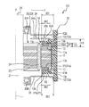
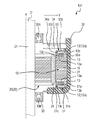
- FIG. 1 is a half sectional view of a motor according to a first embodiment of the present invention.
- FIG. 2 is a plan sectional view of the motor taken along line 2-2 in FIG.
- FIG. 3 is a plan sectional view of the motor taken along line 3-3 in FIG.
- FIG. 4 is an exploded perspective view of the motor.
- FIG. 5 is an enlarged half sectional view of the main part of the motor.
- FIG. 6 is a half cross-sectional view of a modification of the motor according to the embodiment.
- FIG. 7 is a half sectional view of a motor according to the second embodiment of the present invention.
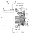
- FIG. 8 is a half sectional view of a motor according to the third embodiment of the present invention.
- FIG. 1 is a half sectional view of a motor according to a first embodiment of the present invention.
- FIG. 2 is a plan sectional view of the motor taken along line 2-2 in FIG.
- FIG. 3 is a plan sectional view of the motor taken along line 3
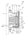
- FIG. 9 is a half sectional view of a motor according to the fourth embodiment of the present invention.
- FIG. 10 is an enlarged half sectional view of the main part of the motor.
- FIG. 11 is a half sectional view of a modified example of the motor.
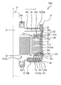
- FIG. 12 is a half sectional view of a motor according to the fifth embodiment of the present invention.
- FIG. 13 is a half sectional view of a modified example of the motor.
- FIG. 14 is a half sectional view of another modified example of the motor.
- FIG. 15 is a half sectional view of another modified example of the motor.
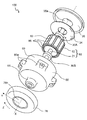
- FIG. 16 is an exploded perspective view of a motor according to the sixth embodiment of the present invention.
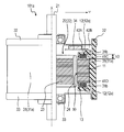
- FIG. 17 is a sectional view of the motor.
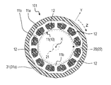
- FIG. 18 is a plan sectional view taken along the line 18-18 in FIG. 17 of the motor.
- FIG. 19 is a perspective view of the appearance of the motor.
- FIG. 20 is an exploded perspective view of another motor according to the sixth embodiment of the present invention.
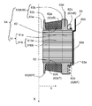
- FIG. 21 is a cross-sectional view showing a cross-section of the inner metal cover of the motor and a cross-section of the coil wound around the tooth.
- FIG. 22 is an exploded perspective view of the motor coil assembly and the metal inner cover.
- FIG. 23 is a configuration diagram in which a metal inner cover is arranged on the outer periphery of the motor coil assembly.
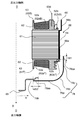
- FIG. 24 is a view for explaining the metal outer cover of the motor.
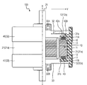
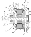
- FIG. 25 is a sectional view of a motor according to the seventh embodiment of the present invention.
- FIG. 26 is a perspective view of the metal inner cover in the motor.
- FIG. 27 is a cross-sectional view of the metal inner cover and coil assembly in the motor.
- FIG. 28 is a cross-sectional view of a motor according to the eighth embodiment of the present invention.
- FIG. 29 is an enlarged cross-sectional view of the vicinity of the notch in the motor.
- FIG. 30 is a plan sectional view taken along line 30-30 in FIG. 29 of the motor.
- FIG. 31 is an enlarged sectional view of the vicinity of another notch in the motor.
- FIG. 32 is a cross-sectional view of a motor according to the ninth embodiment of the present invention.
- FIG. 33 is an enlarged view of the vicinity of the metal outer cover in the motor.
- FIG. 34 is a partial cross-sectional view showing a modified example of the motor.
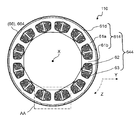
- FIG. 35 is a plan sectional view showing a state before caulking, in which a metal inner cover is fitted into the coil assembly of the motor according to the tenth embodiment of the present invention.
- FIG. 36 is an enlarged cross-sectional view of the AA portion of FIG. 35 in the motor.
- FIG. 37 is a perspective view showing the external appearance of the motor coil assembly.
- FIG. 38 is a sectional view of a motor according to the eleventh embodiment of the present invention.
- FIG. 39 is an exploded perspective view of the terminal cap, the metal inner cover, and the coil assembly in the motor.
- FIG. 40 is a partially enlarged cross-sectional view of a motor according to the twelfth embodiment of the present invention.
- FIG. 41 is a front sectional view of a conventional motor.
- the motor according to the embodiment of the present invention can more reliably prevent fire and smoke from being emitted from the motor by the configuration described later.
- a non-combustible layer that covers at least the coil end is provided in the motor molded with the mold resin.
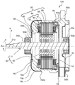
- FIG. 1 is a half sectional view of a motor 101 according to a first embodiment of the present invention.
- 2 is a plan sectional view of the motor 101 taken along line 2-2 in FIG. 3 is a plan sectional view of the motor 101 taken along line 3-3 in FIG.
- FIG. 4 is an exploded perspective view of the motor 101.
- FIG. 5 is an enlarged half sectional view of the main part of the motor 101.
- the motor 101 includes a stator 10, a rotor 20 positioned inside the stator 10, a pair of bearings 30 ⁇ / b> A and 30 ⁇ / b> B, and a mold resin 31 covering the stator 10. Yes. Further, the rotor 20 has a rotation shaft 21 disposed at the center thereof. And the rotor 20 is rotatably supported by the both sides of this rotating shaft 21 being respectively hold
- the illustrated motor 101 is a brushless motor. Further, in the present embodiment, the motor 101 includes the first and second brackets 32 and 33 made of metal and forming a part of the outer shell (housing) of the motor 101 and having a substantially disc shape in plan view, A circuit board 34 is also provided.
- the stator 10 includes a stator core 11 formed by stacking a plurality of metal plates, and a coil 12 wound around the stator core 11.
- the stator core 11 includes a yoke 11 a formed in an annular shape so as to surround the rotor 20 disposed along the axis X of the rotating shaft 21, and the axis X from the yoke 11 a.
- a plurality of teeth 11b protruding in a convex shape toward the top.
- teeth and “tooth” are used properly.
- the plurality of tooth portions protruding in the center direction of the annular stator core are referred to as teeth (plural types of teeth).
- one tooth portion is referred to as tooth.
- the axis X may be referred to as the axial direction X.
- the rotor 20 includes a rotating shaft 21 extending in the axial center X direction, a rotating body 22 including a magnet component, extending in the axial center X direction and fixed to the rotating shaft 21,
- the rotating body 22 is configured by assembling a plurality of magnets 24 as permanent magnets on the outer peripheral surface of the rotor core 23 so that the polarities of adjacent magnets 24 are alternated.
- the rotating shaft 21 of the rotor 20 is rotatably supported by a bearing 30A fitted in the central portion of the first bracket 32 and a bearing 30B fitted in the central portion of the second bracket 33, and consequently the rotor 20 Is supported rotatably.
- the coil 12 is wound around the stator core 11 via an insulator 13 made of an insulator such as resin.
- the insulator 13 schematically includes a bottom surface portion 13a, an outer peripheral wall portion 13b, and an inner peripheral wall portion 13c.
- the bottom surface portion 13 a of the insulator 13 is attached to the end surface of the stator core 11 or the like.
- the bottom surface portion 13 a of the insulator 13 is formed by a surface extending in a direction intersecting with the axis X.
- the outer peripheral wall portion 13b of the insulator 13 is erected on the outer peripheral side of the portion where the coil 12 is wound to regulate the coil position.
- the outer peripheral wall portion 13 b of the insulator 13 is formed by a wall surface extending in a direction along the axis X.
- the inner peripheral wall portion 13c of the insulator 13 is erected on the inner peripheral side of the portion around which the coil 12 is wound to regulate the coil position.
- the inner peripheral wall portion 13 c of the insulator 13 is formed by a wall surface extending in a direction along the axis X.
- the inner peripheral wall 13c of the insulator 13 is located closer to the axis X side than the outer peripheral wall 13b.
- the insulator 13 is not limited to this shape as long as it can insulate between the coil 12 and the stator core 11.
- the coil 12 has a coil end 12a protruding from the stator core 11 in the direction of the axis X. In FIG. 1 and FIG. 5, the coil end 12a protrudes from the stator core 11 above and below the page. As shown in FIGS. 2 and 3, a portion of the coil 12 other than the coil end 12 a is housed in the stator core 11. And the coil 12, the insulator 13, and the stator core 11 of the stator 10 are covered with the mold resin 31 except for the inner peripheral surface of each tooth 11b. Further, the outer peripheral surface side portion of the mold resin 31 is formed in a cylindrical shape, and forms a body portion (case body portion) 31 a that is a part of the outer shell portion (housing) of the motor 101.
- drum 31a is engage
- an electronic component 34 a that forms a connection circuit to the coil 12, various control circuits, a safety protection circuit, and the like on a part of the portion of the mold resin 31 that covers the coil 12.
- a circuit board 34 to which is attached is attached.
- the motor 101 is provided with non-combustible layers 41A, 41B, 42A, 42B, and 43 that cover the coil end 12a.
- a non-combustible layer made of air in the space portion so as to further cover the coil end mold portion 31 b which is a portion covering the coil end 12 a in the mold resin 31 from the outside. 41A, 41B, 42A, 42B, and 43 are provided.
- a groove-shaped recess is formed at a location between the coil end mold portion 31b and the body portion 31a, and nonflammable layers 41A and 41B that become the groove are formed by the air in the space of the groove-shaped recess.
- These non-combustible layers 41 ⁇ / b> A and 41 ⁇ / b> B are extended so as to include at least a dimension range corresponding to the coil end 12 a in the axial center X direction at a position on the outer peripheral side of the coil end 12 a in the mold resin 31.
- the dimension h1 of the incombustible layers 41A and 41B in the axial center X direction is provided with the coil end mold portion 31b and the attachment portion of the insulator 13 to the end surface of the stator core 11 with respect to the axial center X direction. It is formed so as to be longer than the dimension h3.
- 41B are located on the outer peripheral side of the coil end 12a.
- the incombustible layers 41 ⁇ / b> A and 41 ⁇ / b> B are located between the coil end 12 a and the mold resin 31.
- the height h1 of the incombustible layers 41A and 41B is higher than the height h2 of the coil end 12a.
- the coil end mold part 31b excluding the attachment part of the circuit board 34 and the circuit board 34, and the coil end mold part 31b and the first bracket 32 are provided.
- spaces are formed, and the incombustible layers 42A and 42B are formed by the air in each space.
- a space is also formed between the coil end mold part 31 b on the side close to the second bracket 33 and the second bracket 33, and the incombustible layer 43 is formed by the air in this space.
- noncombustible layers 42A, 42B, and 43 are formed to extend in the radial direction Y at a position opposite to the stator core 11 with respect to the coil end 12a, that is, on the outer side in the axial center direction.
- incombustible layers 42A, 42B, and 43 that are spaces are provided in the dimension range in the radial direction Y where the coil end mold portion 31b is provided.
- the incombustible layers 42A and 42B are located in a direction opposite to the direction in which the stator core 11 is located with respect to the coil end 12a.
- the width W1 of the space formed by the incombustible layers 42A and 42B is wider than the width W2 of the coil end 12a.
- the incombustible layer 43 is positioned in a direction opposite to the direction in which the stator core 11 is positioned with respect to the coil end 12a.
- the width W3 of the space formed by the incombustible layer 43 is wider than the width W2 of the coil end 12a.
- non-combustible layers 41A and 41B are provided so as to extend in the axial center X direction at positions on the outer peripheral side with respect to the coil end 12a. For this reason, even when the fire is about to spread as described above, the fire and smoke are blocked by the non-combustible layers 41 ⁇ / b> A and 41 ⁇ / b> B, and it is difficult to go out of the motor 101.
- incombustible layers 42A, 42B, and 43 are provided so as to extend in the radial direction Y on the side opposite to the stator core 11 from the coil end 12a. For this reason, even when a fire is about to spread as described above, the fire and smoke are blocked by the non-combustible layers 42 ⁇ / b> A, 42 ⁇ / b> B, 43, and it is difficult to go out of the motor 101.
- the incombustible layers 41A and 41B formed so as to extend with respect to the axial center X direction at positions on the outer peripheral side of the coil end 12a are The case where it forms in parallel is illustrated.
- the present invention is not limited to this, and the incombustible layer only needs to be at least partially connected in the direction of the axis X even if the distance from the axis X varies.
- incombustible layers 42A, 42B, and 43 formed so as to extend in the radial direction Y on the side opposite to the stator core 11 (outside in the axial center X direction) are formed so as to be substantially along the radial direction Y. The case is shown.
- the present invention is not limited to this, and the incombustible layer only needs to be at least partially connected to the radial direction Y even if the position in the axial center X direction varies.
- the first bracket 32 is further provided on the outer side of the incombustible layer 42A in the axial center X direction, that is, on the side opposite to the stator core 11 with respect to the coil end 12a.
- this 1st bracket 32 functions as a metal cover which covers coil end 12a further, can prevent more reliably that a fire and smoke come out from motor 101 outside, and can improve reliability. .
- the non-combustible layers 41A and 41B formed so as to extend with respect to the axial center X direction at positions on the outer peripheral side with respect to the coil end 12a have the axial X direction.
- the coil end mold portion 31b and the attachment portion of the insulator 13 to the end face of the stator core 11 are extended so as to be longer than the dimension h3 is described.
- the present invention is not limited to this.
- FIG. 6 is a half sectional view of a modification of the present embodiment. That is, as shown in FIG.
- the motor 101a is deeper than the dimension h3 in which the coil end mold portion 31b and the attachment portion of the insulator 13 to the end face of the stator core 11 are provided in the axial center X direction.
- Incombustible layers 41C and 41D are formed so as to bite into the outer peripheral side.
- FIG. 7 is a half sectional view of the motor 102 according to the second embodiment of the present invention.
- the nonflammable layers 41A, 41B, 41C, 41D, 42A, 42B, and 43 are formed of air.
- the present invention is not limited to this, and the nonflammable layer is made of a nonflammable material. May be formed. That is, in the present embodiment, the motor 102 including the non-combustible layers 44 and 45 made of metal will be described.
- the nonflammable layers 44 and 45 are formed of a nonflammable material made of metal.
- the coil end mold portion 31 b is covered with metal incombustible layers 44 and 45 from the outside of the mold resin 31.
- the incombustible layer 44 is formed on the outer peripheral surface of the body portion 31a of the mold resin 31 so as to extend in the axial center X direction at a position on the outer peripheral side of the coil end 12a adjacent to the circuit board 34. ing. That is, the incombustible layer 44 is formed so as to include the coil end mold portion 31b in the axial center X direction.
- the incombustible layer 44 is located on the outer peripheral side with respect to the coil end 12a. Further, in the axial center X direction, the height h11 of the incombustible layer 44 is higher than the height h2 of the coil end 12a.
- the incombustible layer 45 extends from the outer peripheral surface of the body portion 31a of the mold resin 31 to the vicinity of the bearing 30B. More specifically, the incombustible layer 45 extends in the axial center X direction at a position on the outer peripheral side of the outer peripheral surface of the body portion 31a of the mold resin 31 with respect to the coil end 12a adjacent to the second bracket 33, It is formed so as to include the coil end mold portion 31b with respect to the axial center X direction. At the same time, the incombustible layer 45 extends in the radial direction Y at a position opposite to the stator core 11 with respect to the coil end 12a, and is formed so as to include the coil end mold portion 31b with respect to the radial direction Y. Yes.
- the incombustible layer 45 is formed so as to cover the coil end 12a from the end 45a located in the direction along the axis X to the end 45b located in the radial direction Y. Specifically, in the direction along the axis X, the height h12 of the incombustible layer 45 is higher than the height h2 of the coil end 12a. In the radial direction Y, the width W31 of the incombustible layer 45 is wider than the width W2 of the coil end 12a.
- non-combustible layers 44 and 45 formed of a non-combustible material made of metal are provided. For this reason, even when this fire tries to spread to the outer peripheral side of the motor 102, the non-combustible layers 44 and 45 block the fire and accompanying smoke and prevent the fire and smoke from coming out of the motor 102. it can.
- the incombustible layer 45 or the incombustible layer are blocked by 42 ⁇ / b> A, 42 ⁇ / b> B, and 44, and it is possible to prevent fire and smoke from being emitted to the outside of the motor 102.
- metal materials such as iron, stainless steel, brass, and aluminum, can be used for the nonflammable layers 44 and 45 made of metal shown in the above description.
- the rust prevention function can be improved by plating the surface.
- a hot dip galvanized steel sheet JIS standard: SGCD
- an electrogalvanized steel sheet JIS standard: SECD
- non-combustible layers 44 and 45 are formed of a non-combustible material made of metal.
- the present invention is not limited to this, and instead of this, a ceramic, an aluminum hydroxide molded product, or the like Inorganic materials may be used.
- FIG. 8 is a half sectional view of a motor 103 according to the third embodiment of the present invention.
- the metal cover portions 46 and 47 are formed by extending the first and second brackets 32 and 33.
- the present invention is not limited to this, like the incombustible layer 44 in FIG. A metal cover may be provided individually.
- FIG. 9 is a half sectional view of a motor 104 according to the fourth embodiment of the present invention.
- FIG. 10 is an enlarged half sectional view of the main part of the motor 104.
- the coil end 12a and the insulator 13 holding the coil end 12a are covered with non-combustible layers 50 and 51 as shown in FIG.
- the incombustible layers 50 and 51 may be air, but incombustible materials such as metals and ceramics are more suitable. Further, the space between the non-combustible layers 50 and 51 and the coil end 12 a may be air or may be filled with the mold resin 31.
- the incombustible layers 50 and 51 are made of a cap-shaped metal.
- the non-combustible layers 50 and 51 are formed so as to surround the coil end 12a and the insulator 13 that holds the coil end 12a. More specifically, as shown in FIG. 10, the incombustible layer 50 is on the outer peripheral portion 50 a at a position on the outer peripheral side of the outer peripheral wall portion 13 b of the insulator 13 and on the side opposite to the stator core with respect to the insulator 13. It is comprised from the side surrounding part 50b of a position, and the inner peripheral part 50c of the position of the inner peripheral side rather than the inner peripheral wall part 13c of the insulator 13.
- the incombustible layer 51 includes an outer peripheral portion 51a, a side surrounding portion 51b, and an inner peripheral portion 51c.
- the incombustible layers 50 and 51 have outer peripheral portions 50a and 51a and inner peripheral portions 50c and 51c, respectively.
- the outer peripheral portions 50 a and 51 a are located on the outer peripheral side of the outer peripheral wall portion 13 b of the insulator 13.
- the inner peripheral portions 50 c and 51 c are located closer to the axial center X than the inner peripheral wall portion 13 c of the insulator 13.
- the non-combustible layers 50 and 51 have side surrounding portions 50b and 51b, respectively.
- the side surrounding portions 50b and 51b are positioned so as to face the bottom surface portion 13a with the coil end 12a interposed therebetween.
- the incombustible layers 50 and 51 include outer peripheral portions 50a and 51a formed so as to extend in the axial center X direction at positions on the outer peripheral side of the coil end 12a and the outer peripheral wall portion 13b of the insulator 13. Have. Therefore, for example, when a fire starts from the coil end 12a and fire spreads to the outer peripheral side in the radial direction Y from the coil end 12a or the insulator 13, the outer peripheral portions 50a and 51a Smoke is blocked and it can be prevented from exiting the motor 104.
- the non-combustible layers 50 and 51 are side enclosing portions 50b and 51b formed so as to extend with respect to the radial direction Y on the side opposite to the stator core 11 from the coil end 12a, that is, on the outer side in the axial center direction. have. Therefore, for example, when a fire starts from the coil end 12a and the fire is going to spread from the coil end 12a or the insulator 13 to the side opposite to the stator core 11 in the axis X direction, the side encircling portion 50b , 51b can block the fire and smoke and prevent them from coming out of the motor 104.
- the incombustible layers 50 and 51 include inner peripheral portions 50c and 51c formed so as to extend with respect to the axial center X direction at positions closer to the inner peripheral side than the inner peripheral wall portion 13c of the coil end 12a and the insulator 13. Have. Therefore, for example, when a fire breaks out from the coil end 12a and fire spreads to the inner peripheral side in the radial direction Y from the coil end 12a or the insulator 13, the inner peripheral portions 50c and 51c Smoke is blocked and it can be prevented from exiting the motor 104.
- the cross-sectional shape of the incombustible layers 50 and 51 is substantially U-shaped.
- the shape is not limited to this, and the shape can be satisfactorily covered from the outside of the coil end 12a and the insulator 13. If there is, there is no problem.
- the present invention is not limited to this, and a configuration disclosed in a half sectional view of a modification of the present embodiment shown in FIG. That is, the motor 104a shown in FIG.
- 11 includes outer peripheral portions 52a and 53a and side surrounding portions 52b and 53b as non-combustible layers 52 and 53. Even if it is a structure which does not have such an inner periphery part, it can prevent that a fire comes out from the coil end 12a and a fire goes out to the outer peripheral side or a side from the coil end 12a or the insulator 13. FIG. For this reason, compared with the thing without the nonflammable layers 52 and 53, there exists an effect which suppresses to some extent that a fire comes out from the motor 104a.
- the shaft center X is positioned at the outer peripheral side of the coil end 12a as in the non-combustible layers 41A, 41B, 41C, 41D, 44, 45, 50a, 51a, 52a, 53a.
- It may be configured to have only a portion formed so as to extend with respect to the direction, or opposite to the stator core 11 with respect to the coil end 12a as incombustible layers 42A, 42B, 43, 45, 50b, 51b, 52b, 53b. It may be configured to have only a portion formed so as to extend in the radial direction Y at the position. Whichever form is used, there is an advantage that fire and smoke are hard to be emitted to the outside as compared with a motor having no incombustible layer.
- FIG. 12 is a half sectional view of a motor 105 according to the fifth embodiment of the present invention.
- the coil end 12a is covered with a non-combustible layer such as the non-combustible layers 44 and 45 has been described.
- the crossover wire 12b of the coil 12 is also covered by the non-combustible layers 54 and 55. That is, like a normal motor, the motor 105 is provided with a crossover 12b that connects the coils 12 across each tooth (11b) on the outer periphery of the outer peripheral wall portion 13b of the insulator 13.
- incombustible layers 54 and 55 are provided so as to cover these crossover wires 12b.
- the incombustible layers 54 and 55 are made of an incombustible material such as an annular metal plate. Further, the incombustible layers 54 and 55 are formed to extend in the axial center X direction at positions on the outer peripheral side of the coil end 12a, the outer peripheral wall portion 13b of the insulator 13, and the crossover wire 12b. In addition to the coil end 12a and the outer peripheral wall portion 13b of the insulator 13, the non-combustible layers 54 and 55 also cover the crossover wire 12b from the outer peripheral side. Further, the height h21, which is the dimension of the incombustible layers 54 and 55 in the axial center X direction, causes sparks due to the disconnection of the connecting wire 12b or the like.
- drum 31a The height which does not fly to the trunk
- drum 31a should just be ensured.
- the incombustible layers 54 and 55 are made of air, the incombustible layers 54 and 55 need to secure a dimension in the radial direction Y equal to the height h21 in addition to the dimension in the axial center X direction.
- the motor 105 is provided with the non-combustible layers 54 and 55 that cover not only the coil end 12a of the coil 12 of the stator 10 but also the connecting wire 12b.
- the conducting wire forming the coil 12 of the stator 10 may be disconnected.
- a safety protection circuit that prevents an excessive current from flowing through the coil 12 of the stator 10 does not function normally, an excessive current will flow through the conducting wire that forms the coil 12 of the stator 10.
- the connecting wire 12b connecting the coils 12 may break.
- a spark is generated in the disconnected portion, and a spark may be generated.
- the spark generated by the spark may ignite by igniting the gas generated from the insulator 13 or the like.
- the incombustible layers 54 and 55 are formed so as to extend with respect to the axial center X direction at positions on the outer peripheral side of the outer peripheral wall portion 13b and the connecting wire 12b of the insulator 13. Therefore, for example, when a fire breaks out from the connecting wire 12b and the fire spreads to the outer peripheral side in the radial direction Y from the insulator 13 or the connecting wire 12b, the fire and smoke are blocked by the non-combustible layers 54 and 55. Thus, it is possible to prevent fire and smoke from coming out of the motor 105.
- the present invention is not limited thereto. That is, it is good also as a structure disclosed in the half cross section of the modification of this Embodiment shown as FIG.
- the motor 105a shown in FIG. 13 may be configured so as to cover not only the coil end 12a and the connecting wire 12b in the coil 12 of the stator 10 but also the outer peripheral side of the stator core 11 by one incombustible layer 56. Also by this, fire and smoke are blocked by the non-combustible layer 56, and it is possible to prevent fire and smoke from coming out of the motor 105a.
- the incombustible layers 57 and 58 may be disposed on the inner peripheral side and the outer peripheral side of the mold resin 31.
- these nonflammable layers 57 and 58 are comprised with nonflammable materials, such as a metal plate and a ceramic.
- the incombustible layer 57 is formed so as to extend in the axial center X direction on the inner peripheral side of the mold resin 31. That is, the incombustible layer 57 is formed so as to include the one coil end 12a, the insulator 13, the crossover wire 12b, and the stator core 11 that are in the vicinity of the circuit board 34 and the first bracket 32 with respect to the axial center X direction. Yes. Thus, the incombustible layer 57 covers these members from the outer peripheral side in the radial direction Y.
- the non-combustible layer 58 is on the outer peripheral side of the mold resin 31 and on the outer side which is the lower side in FIG. It is formed to extend. In other words, the non-combustible layer 58 extends in the axial center X direction at a position on the outer peripheral side of the coil end 12 a adjacent to the second bracket 33 on the outer peripheral surface of the body portion 31 a of the mold resin 31. Further, the incombustible layer 58 is formed so as to include the coil end mold portion 31b or the coil end 12a, the insulator 13, the crossover wire 12b, and the stator core 11 in the axial center X direction as in the present embodiment. .
- the incombustible layer 58 extends in the radial direction Y at a position opposite to the stator core 11 with respect to the coil end 12a, and is formed so as to include the coil end mold portion 31b with respect to the radial direction Y. .
- the incombustible layer 58 extends from the end 58a located in the direction along the axis X to the end 58b located in the radial direction Y, as in the coil end 12a or the present embodiment. 12a, insulator 13, and crossover 12b are covered.
- the incombustible layer 57 and the end portion 58a of the incombustible layer 58 overlap with each other in the height range h31 with respect to the axial center X direction. Further, the end 58b of the non-combustible layer 58 and the second bracket 33 overlap with the radial direction Y in the radial range W32.
- the incombustible layers 57 and 58 are axially positioned at the outer peripheral wall portion 13b and the connecting wire 12b of the insulator 13 on the inner peripheral side and the outer peripheral side of the mold resin 31. It is formed so as to extend with respect to the center X direction. Therefore, for example, when a fire breaks out from the connecting wire 12b and fire spreads to the outer peripheral side in the radial direction Y from the insulator 13 or the connecting wire 12b, the non-combustible layers 57 and 58 cause the fire caused by the insulator 13 or the like. Smoke is blocked and it is possible to prevent fire and smoke from coming out of the motor 105b.
- the incombustible layer 57 and the end portion 58a of the incombustible layer 58 overlap with each other in the height range h31 with respect to the axial center X direction. For this reason, when the fire breaks out from the connecting wire 12b or the coil end 12a in the vicinity, the fire and smoke blocking performance is further improved, and it is possible to better prevent the fire and smoke from coming out of the motor 105b. Further, the end 58b of the non-combustible layer 58 and the second bracket 33 overlap with the radial direction Y in the radial range W32. For this reason, when the fire breaks out from the connecting wire 12b or the coil end 12a in the vicinity, the fire and smoke blocking performance is further improved, and it is possible to better prevent the fire and smoke from coming out of the motor.
- the motor 105c shown in FIG. 15 further includes a non-combustible layer 59 on the outer peripheral side of the mold resin 31 so as to overlap with the end of the bulging portion 57a of the non-combustible layer 57 in the height range h33 with respect to the axial direction X.
- the incombustible layer 59 is made of an incombustible material such as a metal plate or ceramic. This also improves the fire and smoke blocking performance, and can better prevent the fire and smoke from coming out of the motor.
- the nonflammable layer 59 may be formed by extending the radially outer peripheral end of the first bracket 32 in the axial center X direction without providing the nonflammable layer 59 separately.
- FIG. 16 is an exploded perspective view of a motor 106 according to the sixth embodiment of the present invention.
- FIG. 17 is a cross-sectional view of the motor 106.
- FIG. 18 is a plan sectional view taken along the line 18-18 in FIG.
- FIG. 19 is a perspective view of the appearance of the motor 106.
- FIG. 20 is an exploded perspective view of another motor according to the sixth embodiment of the present invention.
- a motor 106 as an example of a brushless motor having a permanent magnet in the rotor will be described.
- the direction indicated by X in which the rotating shaft 21 extends is defined as the axial direction.
- the Y direction spreading from the center X of the rotating shaft 21 will be described as the radial direction, and the Z direction that goes around the center point X will be described as the circumferential direction.
- the safety protection circuit does not function normally and an excessive current flows through the coil 62, resulting in a fire from the main body of the motor 106 to the outside.
- a non-combustible layer is provided.
- a metallic metal cover is used as the incombustible layer. More specifically, the metal cover includes a metal inner cover 66 and a metal outer cover 76.
- the motor 106 in the present embodiment includes a stator 60, a rotor 80, a first bracket 35, a circuit board 34, two bearings 30A and 30B, and a metal outer cover. 76.
- a metal inner cover (66) described later is not shown.
- the stator 60 includes a coil assembly 64 including a stator core 61, a coil 62, and an insulator 63.
- the coil assembly 64 is assembled by winding the coil 62 around the stator core 61 through the insulator 63 made of an insulating material, as in the above-described embodiments.
- the stator core 61 includes a ring-shaped yoke 61a and a plurality of teeth 61b extending radially inward from the inner peripheral surface of the yoke 61a.
- the plurality of teeth 61b are arranged at equal intervals in the circumferential direction Z while forming slots 61c, which are openings, between each other.
- slots 61c which are openings, between each other.
- a tooth tip portion 61bb extending in the circumferential direction Z is formed at the extended tip portion of each tooth 61b so as to be wider than the extending tooth intermediate portion 61ba.
- the inner peripheral surface of the tooth tip portion 61bb becomes a magnetic pole surface facing the outer peripheral surface of the rotor 80.
- a coil 62 is formed by winding the winding around each tooth 61b while passing the winding through the opening space of the slot 61c with respect to the stator core 61 having such a configuration. Further, the coils 62 are connected by, for example, a jumper as described in the fifth embodiment.
- Such a coil 62 for each tooth 61b is energized and driven by, for example, a three-phase alternating current having a U phase, a V phase, and a W phase that are 120 degrees electrically different from each other.
- the stator 60 protrudes from the stator 60 as shown in FIG. 16 and a metal inner cover 66 that is arranged so as to surround the outer periphery of the stator core 61. And a second bracket 65 arranged as described above.
- the stator 60 includes a coil assembly 64, a metal inner cover 66, and a second bracket 65 arranged at predetermined positions, and the inner peripheral surface of each tooth (61b) and the second Except for the protruding portion of the bracket 65, these members are integrally molded with a mold resin so as to be covered with a resin material.
- the stator 60 including the mold resin portion 69 in which these members are integrated with the mold resin is configured.
- the stator 60 configured as described above has a substantially cylindrical shape, and further, an attachment portion 69a for attaching the motor 106 to an external device, a wiring hole 69b, and the like are formed on the column surface. Yes.
- one of the circular both surfaces of the stator 60 is open, the first bracket 35 is mounted so as to cover the opening, and the other surface is closed.
- Two brackets 65 are arranged so as to protrude. The configuration of the stator 60 will be described in detail below.
- the motor 106 is an inner rotor type motor in which the rotor 80 is disposed inside the stator 60, and this embodiment also gives an example of such an inner rotor type motor 106.
- the rotor 80 includes a rotating body 82 that holds a magnet 84 around a rotating shaft 21 that is rotatably held by a bearing 30A and a bearing 30B.
- the rotating body 82 includes a rotor core 83, a magnet 84, and a rotor resin portion 86.
- the rotor core 83 is configured, for example, by laminating a plurality of thin iron plates in the axial direction X, and is fixed to the rotating shaft 21 at a substantially central portion of the rotating shaft 21.
- the magnet 84 is a permanent magnet, and is disposed inside the rotor core 83 in the present embodiment.
- the rotor core 83 is formed with a plurality of magnet insertion holes 83a penetrating in the axial direction X at equal intervals in the circumferential direction Z.
- One magnet 84 is inserted into each magnet insertion hole 83a.
- an IPM (Interior Permanent Magnet) type motor 106 in which a magnet 84 is included in such a rotor core 83 is shown.
- an example is shown in which the number of magnetic poles is 10 so that the magnetic poles of the S pole and the N pole of the magnet 84 alternate in the circumferential direction Z. That is, in the present embodiment, an example of a brushless motor having 10 poles and 12 slots as the motor 106 is given.
- the rotor resin portion 86 is formed by molding so that both ends of the magnet insertion hole 83a into which the magnet 84 is inserted in the rotor core 83 are covered with a resin material.
- a rotating body 82 is configured.
- the rotor core 83 is also provided with a resin through hole 83b penetrating in the axial direction X.
- the rotor resin portion 86 is formed with disc-shaped end plate resin portions 86a arranged so as to sandwich the magnets 84 in the axial direction X at both axial end portions thereof.
- the resin through hole 83b of the rotor core 83 is also filled with a resin material, thereby connecting the end plate resin portion 86a with the resin in the axial direction X.
- the resin material filled in the resin through hole 83 b constitutes the internal resin portion 86 b as a part of the rotor resin portion 86.
- each of the magnets 84 is securely fixed to the rotor core 83 by such a rotor resin portion 86.
- the magnet 84 is prevented from coming into contact with water. it can.
- the inner rotor type motor 106 will be described as an example. However, as shown in FIG. 20, the surface holding the magnet on the outer peripheral surface of the rotor 80 as in the first to fifth embodiments.
- a magnet-type motor (Surface Permanent Magnet Motor: SPM motor) may be used.
- the rotor 80 is constituted by the rotating body 82 having a cylindrical shape as shown in FIG. 16 and the rotating shaft 21 penetrating through the center of the rotating body 82.
- the rotating shaft 21 to which such a rotating body 82 is fastened is rotatably supported by two bearings of a bearing 30A and a bearing 30B.
- the bearings 30A and 30B are bearings having a plurality of small-diameter balls.
- such bearings 30 ⁇ / b> A and 30 ⁇ / b> B are fixed via metal first brackets 35 and second brackets 65 arranged on both sides in the axial direction of the stator 60.
- the first bracket 35 has a substantially disk shape and is configured to be attachable to the opening side of the stator 60. Further, a holding portion 35a that is recessed in a cylindrical shape is formed at the center of the first bracket 35, and the bearing 30A is held by the holding portion 35a. That is, by attaching the first bracket 35 in which the bearing 30A is inserted into the holding portion 35a to the stator 60, one side of the rotating shaft 21 is instructed to be rotatable.
- the second bracket 65 has a diameter smaller than that of the first bracket 35 and is formed by combining a disk and a cylinder. Further, the second bracket 65 is fixed to the mold resin portion 69 of the stator 60 by the molding described above. Further, a holding portion 65a that is recessed in a cylindrical shape is formed at the center portion of the second bracket 65, and the bearing 30B is held by the holding portion 65a. That is, by inserting the bearing 30B into the holding portion 65a, the other side of the rotating shaft 21 is instructed to be rotatable with respect to the stator 60. In the present embodiment, an opening 65b is formed at the center of the holding portion 65a, and the rotary shaft 21 protrudes outward through the opening 65b. The projecting portion of the rotating shaft 21 becomes an output shaft 21p for connecting a load or the like.
- a metal outer cover 76 made of metal is attached to the second bracket 65 side of the stator 60.
- the metal outer cover 76 has a hollow cup shape with an opening 76h at the center.
- the metal outer cover 76 is attached to the stator 60 so that the second bracket 65 included in the stator 60 penetrates the opening 76 h of the metal outer cover 76.
- the motor 106 incorporates the circuit board 34 on the opening side of the stator 60.
- the circuit board 34 in the present embodiment has a substantially disk shape, and an opening 34b for passing the rotating shaft 21 is formed in the center.
- An electronic component (34a) such as a drive circuit is mounted on the circuit board 34, and a connection line for applying a power supply voltage and a control signal is also connected thereto. And the connection line for connecting with the outside is pulled out through the wiring holder 68 attached to the wiring hole 69b.
- the motor 106 is configured by the following procedure. That is, first, the stator 60 is configured by arranging the coil assembly 64, the metal inner cover 66, and the second bracket 65 at predetermined positions and integrally molding them.
- the bearings 30 ⁇ / b> A and 30 ⁇ / b> B are mounted on both sides of the rotating shaft 21 of the rotor 80. Then, the rotor 80 with the bearings 30A and 30B mounted thereon is inserted into the stator 60 so that the output shaft 21p protrudes from the opening 65b of the second bracket 65. Next, the bearing 30 ⁇ / b> B is press-fitted into the holding portion 65 a of the second bracket 65. Next, the circuit board 34 is mounted on the opening side of the stator 60.
- connection line connected to the circuit board 34 is drawn out through the wiring holder 68.
- the bearing 30A is press-fitted into the holding portion 35a of the first bracket 35, and the first bracket 35 is mounted on the opening side of the stator 60 so as to cover the same.
- the metal outer cover 76 is attached to the second bracket 65 side of the stator 60. In this way, the motor 106 as shown in FIG. 19 is completed.
- the coil 62 is energized and driven by the drive circuit mounted on the circuit board 34 by supplying a power supply voltage, a control signal, and the like to the motor 106 configured as described above via a connection line.
- a drive current flows through the coil 62 and a magnetic field is generated from the stator core 61.
- the alternating magnetic field from the stator core 61 and the magnetic field from the magnet 84 of the rotor 80 generate an attractive force and a repulsive force according to the polarities of the magnetic fields, and the rotor 80 rotates around the rotary shaft 21 by these forces. Rotate in direction Z.
- stator 60 including the inner metal cover 66 in the motor 106 configured as described above will be described.
- FIG. 21 is a cross-sectional view showing a cross-section of the inner metal cover 66 and a cross-section of the coil 62 wound around the tooth 61b.
- FIG. 22 is an exploded perspective view of the coil assembly 64 and the metal inner cover 66.
- FIG. 23 is a configuration diagram in which a metal inner cover 66 is disposed on the outer periphery of the coil assembly 64.
- the insulator 63 generally includes a bottom surface portion 63a, an outer peripheral wall portion 63b, and an inner peripheral wall portion 63c.
- the bottom surface portion 63a is formed by a surface orthogonal to the axial direction X.
- the surface formed on the bottom surface portion 63 a is attached to the end surface in the axial direction X of the stator core 61.
- the outer peripheral wall 63b and the inner peripheral wall 63c are formed by wall surfaces parallel to the axial direction X.
- Such an outer peripheral wall part 63b is erected on the outer peripheral side of the place where the coil 62 is formed, and regulates the coil position.
- a pin 63 d is attached to the outer peripheral wall 63 b so as to protrude toward the opposite side of the stator core 61. As shown in FIG. 17, the pin 63 d electrically connects the coil 62 wound around the tooth (61 b) and the circuit board 34. The pin 63 d passes through the terminal cap 36 and is connected to the circuit board 34. Furthermore, as shown in FIG. 21, the inner peripheral wall 63c is positioned radially inward from the outer peripheral wall 63b, and is erected on the inner peripheral side of the location where the coil 62 is formed to restrict the coil position. .
- Such a bottom surface portion 63a of the insulator 63 is attached to each of both surfaces located at the end in the axial direction X of the tooth 61b.
- the winding is wound through the pair of insulators 63 attached.
- one coil 62 is formed for the stator core 61.
- a similar coil 62 is formed for each tooth 61b, and the coils 62 are electrically connected according to a predetermined connection pattern, thereby completing a coil assembly 64 as shown in FIG.
- the coil 62 has a coil end 62a that protrudes from the stator core 61 to both sides in the axial direction X.
- the portion of the coil 62 other than the coil end 62 a is housed in the slot 61 c of the stator core 61.
- a connecting wire 62 b that connects the coils 62 is disposed between the teeth 61 b on the outer periphery of the outer peripheral wall 63 b of the insulator 63.
- an inner metal cover 66 as a nonflammable layer is disposed outside the coil assembly 64.
- the inner metal cover 66 is a metal cylinder having a substantially cylindrical shape open on both sides.
- such an inner metal cover 66 is disposed so as to surround the outer periphery of the coil assembly 64 at a predetermined interval in the radial direction from the outer periphery thereof.
- the metal inner cover 66 has a small diameter portion 66a and a large diameter portion 66b having a diameter larger than that of the small diameter portion 66a.
- the inner diameter of the small-diameter portion 66a is substantially equal to the outer diameter of the stator core 61 so that the small-diameter portion 66a can be fitted into the outer periphery of the stator core 61. Further, the dimension in the axial direction X of the small diameter portion 66 a is also substantially equal to the dimension in the axial direction X of the stator core 61.
- the dimension in the axial direction X of the large diameter portion 66b is larger than the dimension in the axial direction X of the coil end 62a.
- Such a large-diameter portion 66b is provided only on one side in the axial direction X of the small-diameter portion 66a in the inner metal cover 66.
- the large-diameter portion 66b of the metal inner cover 66 is disposed so as to surround the coil end 62a and the connecting wire 62b on one side in the axial direction X.
- the insulator 63, the coil end 62a, the connecting wire 62b, and the like are also distinguished as follows in order to make the arrangement of the metal inner cover 66 clearer. That is, in the axial direction X in FIG. 21, the insulator 63B, the coil end 62aB, and the connecting wire 62bB are arranged on one side with respect to the stator core 61, and the insulator 63T, the coil end 62aT, and the connecting wire 62bT are arranged on the other opposite side. Shown to be placed.
- the metal inner cover 66 is arranged so that the large-diameter portion 66b surrounds the insulator 63B, the coil end 62aB, and the connecting wire 62bB.
- the insulator 63T, the coil end 62aT, and the crossover wire 62bT are not surrounded by the inner metal cover 66.
- the outer periphery of the insulator 63T located in the lower part of the figure has a positioning portion 63e that is not included in the insulator 63B located in the upper part of the figure.
- the insulator 63T has the positioning portion 63e, when the metal inner cover 66 is attached, the positional relationship between the small diameter portion 66a and the stator core 61 and the large diameter portion 66b and the insulator 63B is uniquely determined.
- the large diameter portion 66b is formed with a larger diameter than the small diameter portion 66a. Therefore, the large diameter portion 66b is attached to the stator core 61 while maintaining a sufficient insulation distance from the pin 63d.
- the side wall of the terminal cap 36 is located between the large diameter part (66b) and the pin 63d. If the terminal cap 36 is formed of an insulating material, the insulation distance between the large diameter portion (66b) and the pin 63d can be secured with a margin.
- the large-diameter portion 66b of the metal inner cover 66 which is a non-combustible layer, is disposed on the outer peripheral side of the coil end 62aB, the outer peripheral wall 63b of the insulator 63B, and the crossover wire 62bB. For this reason, even if a fire breaks out from the coil 62 due to a failure due to a rare short as described above and the fire spreads to the outer peripheral side in the radial direction from the insulator 63B or the crossover wire 62bB, the large-diameter portion 66b of the metal inner cover 66 The fire and smoke are blocked, and it is possible to prevent fire and smoke from coming out of the motor 106.
- the configuration with the fire prevention measures as shown in FIG. 23 is covered with the resin material of the mold resin portion 69 except for the inner peripheral surface of the tooth 61b. That is, for example, in the fifth embodiment, the insulator 13 and the coil end 12a are exposed in addition to the inner peripheral surface of the tooth 11b, whereas in the present embodiment, only the inner peripheral surface of the tooth 11b is exposed. State. In other words, in the present embodiment, the entire inner metal cover 66 and the entire insulator 63 and coil end 62a are covered with the resin material. In the present embodiment, such a configuration ensures a sufficient holding strength of the coil assembly 64 in the stator 60 while taking the above-described fire prevention measures.
- the insulator 13 used in the fifth embodiment has a protruding portion 63 f that protrudes in the radial direction Y. Therefore, in the case of this configuration, when attaching the incombustible layer 57, particularly the incombustible layer 57 made of a metal material, to the stator core 11, a manufacturing process for winding a plate-like metal material around the stator core 11 is required.
- the cylindrical inner metal cover 66 can be used. Therefore, the work of attaching the metal inner cover 66 to the stator core 61 is facilitated, and the productivity is improved.
- a metal outer cover 76 is further provided as a nonflammable layer.
- the metal outer cover 76 is attached to the outer surface of the mold resin portion 69 of the stator 60.
- the metal outer cover 76 is attached to the outside of the stator 60 on the output shaft 21p side.
- the metal outer cover 76 is disposed at a position opposite to the large diameter portion (66b) of the metal inner cover 66 with respect to the stator core 61 in the axial direction X.
- FIG. 24 is a diagram for explaining the metal outer cover 76.
- the coil assembly 64, the metal inner cover 66, and the second bracket 65 are shown together with the metal outer cover 76 in order to show the positional relationship with other members. That is, as shown in FIG. 17, by attaching the metal outer cover 76, the metal outer cover 76 is larger than the stator core 61 in the axial direction X as shown in FIG. 24. It is arranged at a position opposite to 66b.
- the insulator 63T, the coil end 62aT, and the crossover wire 62bT are disposed on the opposite side of the large diameter portion 66b together with the second bracket 65 from which the output shaft (21p) protrudes.
- the side opposite to the large-diameter portion 66b of the inner metal cover 66 with respect to the stator core 61 is appropriately set as the output shaft side on which the output shaft (21p) is disposed, and the output shaft The opposite side of the side will be described as the opposite output shaft side.
- the metal outer cover 76 includes a top surface portion 76a, a curved surface portion 76b, and a cylindrical portion 76c, and has a hollow cup shape.
- the top surface portion 76a of the metal outer cover 76 has a disk shape and an opening 76h at the center.
- the curved surface portion 76b is bent from the top surface portion 76a into a curved surface at a substantially right angle.
- the cylindrical portion 76c extends in a cylindrical shape from the curved surface portion 76b, and an end portion side of the cylindrical portion 76c is opened. Further, the inner diameter of the cylindrical portion 76 c is made substantially equal to the outer diameter of the stator 60 so that the cylindrical portion 76 c can be fitted into the outer periphery of the stator 60.
- the dimension in the axial direction X of the metal outer cover 76 is such that an overlapping portion 76ca between the cylindrical portion 76c and the metal inner cover 66 in the axial direction X is generated. It is said.
- the attachment position of the metal outer cover 76 is such a position that an overlapping portion 76 ca of the cylindrical portion 76 c and the stator core 61 in the axial direction X is generated when the metal outer cover 76 is attached to the stator 60.
- an example in which the overlapping portion 76ca has a dimension h61 is shown.
- the cylindrical portion 76c overlaps the stator core 61 in the axial direction X as an overlapping portion 76ca on the output shaft side.
- the metal outer cover 76 is arranged with respect to the coil assembly 64 so that the overlapping portion 76ca of the cylindrical portion 76c surrounds the outer periphery of the stator core 61 at a predetermined interval in the radial direction Y from the outer periphery of the stator core 61. Is done.
- the metal outer cover 76 is attached to the stator 60 in such an arrangement relationship with respect to the coil assembly 64. Therefore, the metal outer cover 76 surrounds the insulator 63T, the coil end 62aT, and the crossover wire 62bT and covers these members on the output shaft side.
- the coil end 62aT, the insulator 63T, and the crossover wire 62bT are covered with the metal outer cover 76 that is a non-combustible layer. For this reason, even if the fire breaks out due to a problem such as the above-mentioned rare short and the fire spreads to the outer peripheral side in the radial direction from the insulator 63B or the connecting wire 62bB, the fire and smoke are blocked by the metal outer cover 76, It is possible to prevent fire and smoke from coming out of the motor 106.
- the top surface portion 76a of the metal outer cover 76 serves as the overlapping portion 76aa, and the second bracket. It overlaps with 65 in the radial direction Y. More specifically, a part of the top surface portion 76a outside the outer periphery of the opening 76h is an annular overlapping portion 76aa that overlaps a portion on the outer peripheral side of the second bracket 65 in the radial direction Y.
- FIG. 24 shows an example in which the overlapping portion 76aa has the dimension w62.
- the motor 106 includes the metal inner cover 66 and the metal outer cover 76 as non-combustible layers.
- the stator 60 including the mold resin portion 69 in which these members are integrated is formed by molding the metal inner cover 66 with the side surface of the stator core 61 mounted as described above.
- the large-diameter portion 66b of the metal inner cover 66 is disposed so as to surround the insulator 63B, the coil end 62aB, and the crossover wire 62bB. For this reason, on the side opposite to the output shaft, the large-diameter portion 66b of the metal inner cover 66 can block fire and smoke generated inside the motor 106.
- the metal outer cover 76 is fitted on the outer periphery of the stator 60 as described above. Thereby, on the output shaft side, the metal outer cover 76 is disposed so as to cover the insulator 63T, the coil end 62aT, and the crossover wire 62bT. For this reason, on the output shaft side, the metal outer cover 76 can block fire and smoke generated in the motor 106.
- the metal inner cover 66 and the metal outer cover 76 made of metal have been described as the incombustible layer.
- the metal inner cover 66 and the metal outer cover 76 may be non-combustible materials. That's fine.
- the metal inner cover 66 and the metal outer cover 76 may be made of a material other than metal such as ceramic which is a non-combustible material.
- FIG. 25 is a sectional view of a motor 107 according to the seventh embodiment of the present invention.
- FIG. 26 is a perspective view of the metal inner cover 661 in the motor 107.
- FIG. 27 is a cross-sectional view of the metal inner cover 661 and the coil assembly 641 in the motor 107.
- the motor 107 includes a metal inner cover 661 obtained by modifying the metal inner cover 66 of the sixth embodiment, and the sixth embodiment.
- transformed the insulator 63 of a form is provided. That is, as shown in FIG. 25, the motor 107 includes a stator 601 including a mold resin portion 69 in which a metal inner cover 661 is mounted on a coil assembly 641 including an insulator 631 and these members are integrated.
- Other configurations and operations are the same as those in the sixth embodiment.
- the same components as those in the sixth embodiment are denoted by the same reference numerals, and the same portions are described in the sixth embodiment. The description of the form is used.
- the inner metal cover 661 as a non-combustible layer is also a metal cylinder having both sides opened in a substantially cylindrical shape.
- the inner metal cover 661 further includes a tapered portion 661c in addition to the small diameter portion 66a and the large diameter portion 66b similar to the inner metal cover 66 of the sixth embodiment.
- the tapered portion 661c is provided at the end opposite to the large diameter portion 66b with respect to the small diameter portion 66a.
- the tapered portion 661c has an inversely tapered shape, and its diameter increases as it approaches the end from the boundary with the small diameter portion 66a of the inner metal cover 661.
- the coil assembly 641 has an insulator 631 that is different from the insulator 63 of the sixth embodiment.
- an insulator 63 similar to that in the sixth embodiment is arranged on the counter-output shaft side, whereas an output is provided.
- An insulator 631 is disposed on the shaft side.
- the insulator 631 further includes a tapered portion 631c in addition to the bottom surface portion 63a, the outer peripheral wall portion 63b, and the inner peripheral wall portion 63c similar to those of the sixth embodiment.
- the tapered portion 631 c is disposed so as to be positioned on the outer periphery of the stator core 61.
- the taper portion 631c has a triangular cross section, and the entire taper portion 631c has a reverse taper shape.
- the diameter of the taper portion 631c increases as the end of the stator core 61 is approached.
- the tapered portion 631c is formed so that the angle of the side surfaces and the length in the axial direction X are substantially equal to the tapered portion 661c of the inner metal cover 661.
- the position of the inner metal cover 661 in the axial direction X with respect to the coil assembly 641 is regulated by the tapered portion 661c and the tapered portion 631c.
- the coil assembly 641 includes the insulator 631 having the tapered portion 631c, and the inner metal cover 661 includes the tapered portion 661c that matches the shape of the tapered portion 631c.
- the inner metal cover 661 can be easily fitted into the coil assembly 641.
- the stopper function is realized by such a tapered shape, it can be more easily fitted.
- the position in the axial direction X between the coil assembly 641 and the metal inner cover 661 can be accurately determined by an easy operation such as fitting until the tapered portion 661c and the tapered portion 631c come into contact with each other without shifting the positional relationship. Can be matched.
- the large-diameter portion 66b of the inner metal cover 661 can be accurately arranged around these members with respect to the insulator 63, the coil end 62aB, and the crossover wire 62bB positioned on the side opposite to the output shaft. Therefore, according to the present embodiment, since the large-diameter portion 66b of the inner metal cover 661 that is a non-combustible layer can be arranged with higher accuracy, it is possible to more reliably prevent fire and smoke from coming out of the motor 107.
- FIG. 28 is a sectional view of a motor 108 according to the eighth embodiment of the present invention.
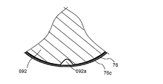
- FIG. 29 is an enlarged perspective view of the motor 108 in the vicinity of the notch 692a.
- 30 is a plan cross-sectional view of the motor 108 taken along line 30-30 in FIG.
- FIG. 31 is an enlarged perspective view of the vicinity of another notch in the motor.
- the motor 108 in this embodiment includes a mold resin portion 692 obtained by deforming the mold resin portion 69 of the sixth embodiment in comparison with the sixth embodiment shown in FIG. Specifically, as shown in FIG. 28, the mold resin portion 692 of the motor 108 is further provided with a notch portion 692a which is a notch with respect to the mold resin portion 69 of the sixth embodiment.
- Other configurations and operations are the same as those in the sixth embodiment.
- the same components as those in the sixth embodiment are denoted by the same reference numerals, and the same portions are described in the sixth embodiment. The description of the form is used. Although details will be described below, in the present embodiment, moisture due to condensation or the like generated in the metal outer cover 76 is released from the main body of the motor 108 by using the notch 692a.
- the notch 692a formed in the mold resin portion 692 in this manner has a substantially circular cross section of the mold resin portion 692, and a portion near the outer periphery thereof is concave in the center direction. Shape. Further, as shown in FIG. 29, the cutout portion 692a has such a cross-sectional shape extending in the axial direction X. That is, the notch portion 692a is a groove or a recess formed so as to cut out a part of the mold resin portion 692.
- the mold resin portion 692 is formed on the side where the metal outer cover 76 is attached. Further, when the metal outer cover 76 is attached to the mold resin portion 692, the notch portion 692a is formed so that the notch portion 692a and the cylindrical portion 76c of the metal outer cover 76 partially overlap as shown in FIG. is doing. In other words, when the metal outer cover 76 is attached to the mold resin portion 692, the cutout portion 692a extends in the axial direction X from the end portion of the metal outer cover 76 to the opposite output shaft side. Thus, in the present embodiment, the notch 692a is also provided with a notch 692a1 in which the notch 692a and the cylindrical portion 76c of the metal outer cover 76 are openings that do not face in the radial direction Y.
- the notch 692a is formed so that the notch 692a and the wiring hole 69b for mounting the wiring holder 68 are at substantially the same position. That is, the wiring hole 69b and the wiring holder 68 are disposed on the extension in the axial direction X from the end of the notch 692a on the side opposite to the output shaft.
- the metal outer cover 76 is attached to the mold resin portion 692 in an exposed state. Furthermore, since the metal outer cover 76 is made of metal, condensation and the like are more likely to occur. For example, moisture is easily accumulated between the mold resin portion 692 and the metal outer cover 76. Therefore, in the present embodiment, the groove-shaped notch 692a as described above is provided to guide moisture generated around the metal outer cover 76 away from the metal outer cover 76.
- FIG. 29 an example of a route through which this moisture flows is indicated by an arrow.
- the motor 108 is fixed inside the device so that the notch 692a and the wiring holder 68 are vertically downward. Then, moisture generated between the mold resin portion 692 and the metal outer cover 76 is first guided to the notch portion 692a. Further, the moisture flows out from the notch opening 692a1 of the notch 692a to the outer surface of the mold resin part 692. Further, the moisture that has flowed out travels on the ground side of the mold resin portion 692 and reaches the wiring holder 68. Then, the lead wire coming out from the wiring holder 68 is appropriately routed for moisture countermeasures, so that the moisture reaching the wiring holder 68 is guided further away from the motor 108 using this lead wire. Can do.
- the mold resin part 692 has the above-mentioned notch part 692a. Therefore, according to the present embodiment, even if moisture adheres to the metal outer cover 76 for preventing fire and smoke from coming out of the motor 108 due to condensation, the moisture is separated from the motor 108. Can be guided as follows.
- FIG. 31 is an enlarged perspective view of the vicinity of another notch in the motor.
- FIGS. 28 is different from the embodiment shown in FIGS. 28 to 30 in that tapered portions 76d and 692a2 are formed in the vicinity of the notch opening 692a1.
- Other components are denoted by the same reference numerals as those shown in FIGS. 28 to 30 and the description thereof is incorporated.
- the end on the side opposite to the output shaft of the metal outer cover 76 has a tapered portion 76d that opens in the radial direction Y.
- the mold resin portion 692 has a tapered portion 692a2 at a position facing the tapered portion 76d.
- the tapered portion 76d and the tapered portion 692a2 form an inclined surface in a direction that opens vertically downward so that the moisture that has passed through the notched portion 692a is smoothly discharged. Therefore, the moisture that has passed through the notch 692a is further led out from the notch 692a.
- FIG. 32 is a sectional view of a motor 109 according to the ninth embodiment of the present invention.
- FIG. 33 is an enlarged view of the motor 109 in the vicinity of the metal outer cover 763.
- the motor 109 in the present embodiment includes a metal outer cover 763 obtained by deforming the metal outer cover 76 of the sixth embodiment in comparison with the sixth embodiment shown in FIG. Specifically, as shown in FIGS. 32 and 33, the metal outer cover 763 of the motor 109 has a tip 763d further having a chamfered portion 763d1 with respect to the metal outer cover 76 of the sixth embodiment. I have. Other configurations and operations are the same as those in the sixth embodiment. The same components as those in the sixth embodiment are denoted by the same reference numerals, and the same portions are described in the sixth embodiment. The description of the form is used.
- the metal outer cover 763 further includes a chamfered portion 763d1 which is a curved surface as a so-called chamfer at the tip end portion 763d on the opening side.
- the tip 763d is rounded by the chamfered portion 763d1 in this manner, thereby facilitating the attachment of the metal outer cover 763 to the mold resin portion 69. Furthermore, by using such a tip portion 763d, scratches and damages due to sharp corners are prevented.
- the chamfered portion 763d1 may be a flat chamfer instead of a curved chamfer.
- FIG. 34 is a partial sectional view showing a modification of the present embodiment.
- the tip end portion 763d on the opening side of the metal outer cover 763 is a tapered portion 763d2 having a reverse taper shape.
- the taper portion 763d2 has a larger diameter as it goes to the counter-output shaft side. Also by this, the metal outer cover 763 can be easily attached to the mold resin portion 69.
- FIG. 35 is a plan sectional view showing a state before caulking, in which the metal inner cover 66 is fitted into the coil assembly 644 of the motor 110 according to the tenth embodiment of the present invention.
- FIG. 36 is an enlarged cross-sectional view taken along the line AA in FIG. 35 and shows a state in which the metal inner cover 66 is attached to the coil assembly 644 and then crimped.
- FIG. 37 is a perspective view showing the appearance of the coil assembly 644 of the motor 110.
- the motor 110 includes a stator core 614 of a coil assembly 644 obtained by modifying the stator core 61 of the coil assembly 64 of the sixth embodiment in comparison with the sixth embodiment shown in FIGS. 17 and 18. , And a metal inner cover 664 obtained by deforming the metal inner cover 66 of the sixth embodiment by caulking. That is, as shown in FIG. 35, the motor 110 includes a stator including a metal inner cover 664 in which the metal inner cover 66 is fitted into the coil assembly 644 and then the metal inner cover 66 is crimped.
- Other configurations and operations are the same as those in the sixth embodiment.
- the same components as those in the sixth embodiment are denoted by the same reference numerals, and the same portions are described in the sixth embodiment. The description of the form is used.
- a protrusion 61d is formed on the outer periphery of the stator core 614.
- the number of the protrusions 61d may be one or more. In the present embodiment, an example is shown in which twelve of the same number as the teeth 61b are formed. In the present embodiment, such protrusions 61 d are formed at equal intervals in the circumferential direction Z on the outer periphery of the stator core 614.
- Each protrusion 61d extends in the axial direction X, and in the radial direction Y, as shown in FIG. 36, has a shape protruding outward in a triangular shape.
- the same inner metal cover 66 as that of the sixth embodiment is fitted into the stator core 614 having the protruding portions 61d.
- the protrusions 61 d protruding in a triangular shape are fitted in contact with the inner peripheral surface of the inner metal cover 66.
- the protrusion 61d can be fitted in a state where the contact area is small, thereby improving workability.
- the caulking tool is used to caulk the portion where the projection 61d is located from the outside of the inner metal cover 66. It is carried out. That is, as shown in FIG. 36, a caulking jig that is recessed in a triangular shape from the outside is pressed against the metal inner cover 66 where the protrusion 61d is located. As a result, the pressed portion of the inner metal cover 66 becomes a protrusion that bends in a triangular shape as shown in FIG. That is, in other words, the inner metal cover 664 having the caulking portion 664c which is a projection as shown in FIG.
- At least one protrusion 61d is formed in the stator core 614, and the caulking portion 664c is formed in the metal inner cover 664 so as to correspond to the protrusion 61d.
- the inner metal cover 664 is held with respect to the coil assembly 64 by the protruding portion 61d and the crimping portion 664c. For this reason, it is possible to prevent misalignment between each other, for example, even during molding. Therefore, according to the present embodiment, it is possible to prevent the large-diameter portion (66b) of the metal inner cover 664, which is a non-combustible layer, from being displaced from a predetermined position during assembly or molding. And more reliably preventing smoke.
- the inner metal cover 664 is held with respect to the coil assembly 64 based on caulking.
- it may be held for spot welding. That is, as described above, the inner metal cover 66 is fitted into the stator core 614 having the protruding portion 61d, the spot where the protruding portion 61d contacts the inner metal cover 66 is spot welded, and the inner metal cover 66 is fixed to the stator core. It is also possible to fix to 614.
- FIG. 38 is a sectional view of a motor 111 according to the eleventh embodiment of the present invention.
- FIG. 39 is an exploded perspective view of the terminal cap 365, the metal inner cover 66, and the coil assembly 64 in the motor 111.
- the motor 111 according to the present embodiment includes a terminal cap 365 obtained by modifying the terminal cap 36 according to the sixth embodiment in comparison with the sixth embodiment illustrated in FIG. Specifically, as shown in FIGS. 38 and 39, the terminal cap 365 of the motor 111 further includes a wall portion 365b with respect to the terminal cap 36 of the sixth embodiment.
- Other configurations and operations are the same as those in the sixth embodiment.
- the same components as those in the sixth embodiment are denoted by the same reference numerals, and the same portions are described in the sixth embodiment. The description of the form is used.
- the terminal cap 365 includes a wall portion 365b in addition to a terminal surface 365a provided with a terminal for electrical connection.
- the terminal cap 365 is formed of an insulating resin as an insulating material.
- such a terminal cap 365 is disposed inside the motor 111 on the side opposite to the output shaft.
- the terminal cap 365 is disposed so that the terminal surface 365 a faces the coil assembly 64.
- the wall part 365b is extended in the axial direction X from the outer peripheral side of the terminal surface 365a. That is, the wall portion 365 b is parallel to the large diameter portion 66 b of the metal inner cover 66.
- the wall portion 365 b is disposed between the large diameter portion 66 b and the outer peripheral wall portion 63 b included in the insulator 63.
- An outer peripheral wall 63b is located between the wall 365b and the coil end 62a.
- the terminal cap 365 is configured to include the wall portion 365b. For this reason, according to this Embodiment, it can prevent that the terminal arrange
- FIG. 40 is a partial enlarged cross-sectional view of a motor 112 according to the twelfth embodiment of the present invention.
- the motor 112 in comparison with the sixth embodiment shown in FIG. 17, includes a mold resin portion 696 obtained by deforming the mold resin portion 69 of the sixth embodiment, and the sixth embodiment.
- transformed the metal outer cover 76 of a form is provided. That is, as shown in FIG. 40, the motor 112 has a recess 696a formed in the mold resin portion 696, and the metal outer cover 766 has a bent portion 766d1 at the tip 766d.
- Other configurations and operations are the same as those in the sixth embodiment.
- the same components as those in the sixth embodiment are denoted by the same reference numerals, and the same portions are described in the sixth embodiment. The description of the form is used.
- the mold resin portion 696 has at least one recess 696a formed near the output shaft on the outer periphery.
- a bent portion 766d1 is formed at the tip end portion 766d of the metal outer cover 766 on the opening side so as to match the concave portion 696a.
- the present disclosure improves the safety of the motor alone even when the safety protection device does not function normally when driving the motor.
- the present disclosure aims to prevent fire and smoke from being emitted from the motor to the outside even in a special environment.
- the coil can serve as a heat source.
- This disclosure prevents the above-described outflow of fire and smoke by surrounding a coil that can be a heat source with a non-combustible layer.
- a coil that can be a heat source with a non-combustible layer.
- air or an incombustible material such as a metal material and ceramic can be used.
- the rotor of the motor rotates around the rotation axis. Therefore, the outer shape of the motor is generally a columnar shape extending in the rotation axis direction. Therefore, the incombustible layer according to the present disclosure needs to surround the columnar side surface, the columnar bottom surface side, and the upper surface side with respect to the coil.
- the applicant of the present application encloses the coil or the coil assembly in a place as close as possible to the possible part, and surrounds the coil or the coil assembly in the possible range for the difficult part.
- the present embodiment has been derived.
- the sixth embodiment that is considered to be useful in manufacturing and against EMC has the following configuration.
- the inner metal cover is directly attached to the stator core around which the coil is wound so as to include the side surface side of the coil end located on the counter-output shaft side.
- This configuration can directly or indirectly surround the entire circumference of the coil assembly. Therefore, if this embodiment is used, it is possible to prevent fire and smoke from being emitted from the motor to the outside even under a special environment, which is the main purpose. In addition, it is possible to easily create forms composed of various outer shapes such as suppression of sound and vibration or presence / absence of an attachment portion, which are characteristics of a molded motor.
- This gap functions as an air layer. That is, during normal motor use, this air layer acts to prevent the heat dissipation of the motor. Therefore, there is an improvement in terms of cooling the motor.
- the metal cover acts as an antenna when the motor is attached to an electric device, so that further improvement is required with respect to EMC.
- the form in which the outer surface of the motor is enclosed by the metal cover is not excluded, but the above-described form in which the coil or the coil assembly is enclosed at a closer position is more preferable.
- the application field of the present invention can be widely used for a so-called molded motor in which a stator is covered with a mold resin.
Landscapes
- Engineering & Computer Science (AREA)
- Power Engineering (AREA)
- Microelectronics & Electronic Packaging (AREA)
- Insulation, Fastening Of Motor, Generator Windings (AREA)
- Motor Or Generator Frames (AREA)
Abstract
Description
図1は、本発明の第1の実施の形態に係るモータ101の半断面図である。図2は、同、モータ101の図1における2-2線矢視平面断面図である。図3は、同、モータ101の図1における3-3線矢視平面断面図である。図4は、同、モータ101の分解斜視図である。また、図5は、同、モータ101の要部拡大半断面図である。
図7は、本発明の第2の実施の形態に係るモータ102の半断面図である。
図8は、本発明の第3の実施の形態に係るモータ103の半断面図である。
図9は、本発明の第4の実施の形態に係るモータ104の半断面図である。また、図10は、同、モータ104の要部拡大半断面図である。
図12は、本発明の第5の実施の形態に係るモータ105の半断面図である。
図16は、本発明の第6の実施の形態に係るモータ106の分解斜視図である。図17は、同、モータ106の断面図である。図18は、同、モータ106の図17における18-18線矢視平面断面図である。また、図19は、同、モータ106の外観の斜視図である。さらに、図20は、本発明の第6の実施の形態に係る他のモータの分解斜視図である。
図25は、本発明の第7の実施の形態に係るモータ107の断面図である。図26は、同、モータ107における金属内カバー661の斜視図である。図27は、同、モータ107における金属内カバー661およびコイル組立641の断面図である。
図28は、本発明の第8の実施の形態に係るモータ108の断面図である。図29は、同、モータ108における切欠き部692a近傍の拡大斜視図である。図30は、同、モータ108の図29における30-30線矢視平面断面図である。また、図31は、同、モータにおける他の切欠き部近傍の拡大斜視図である。
図32は、本発明の第9の実施の形態に係るモータ109の断面図である。図33は、同、モータ109における金属外カバー763近傍の拡大図である。
図35は、本発明の第10の実施の形態に係るモータ110のコイル組立644に金属内カバー66を嵌め込んだカシメ加工前の状態を示す平面断面図である。図36は、図35のAA箇所の拡大断面図であり、金属内カバー66をコイル組立644に装着した後、カシメ加工を施した状態を示している。また図37は、同、モータ110のコイル組立644の外観を示す斜視図である。
図38は、本発明の第11の実施の形態に係るモータ111の断面図である。図39は、同、モータ111における端子キャップ365と金属内カバー66とコイル組立64との分解斜視図である。
図40は、本発明の第12の実施の形態に係るモータ112の部分拡大断面図である。
10,60,601,910 ステータ
11,61,614,911 ステータコア
11a,61a ヨーク
11b,61b ティース(トゥース)
12,62,912 コイル
12a,62a,62aB,62aT,912a コイルエンド
12b,62b,62bB,62bT 渡り線
13,63,63B,63T,631,913 インシュレータ
13a,63a 底面部
13b,63b 外周壁部
13c,63c 内周壁部
20,80,920 ロータ
21 回転軸
21p 出力軸
22,82 回転体
23,83 ロータコア
24,84 磁石
30A,30B 軸受
31,131,931 モールド樹脂
31a 胴部
31b コイルエンドモールド部
32,35 第1のブラケット
33,65 第2のブラケット
34 回路基板
34a 電子部品
34b,65b 開口
35a,65a 保持部
36,365 端子キャップ
41A,41B,41C,41D,42A,42B,43,44,45,50,51,52,53,54,55,56,57,58,59 不燃層
45a,45b,58a,58b 端部
46,47 金属カバー部
50a,51a,52a,53a 外周囲み部
50b,51b,52b,53b 側方囲み部
50c,51c 内周囲み部
57a 膨出部
61c スロット
61d,63f 突起部
61ba トゥース中間部
61bb トゥース先端部
63d ピン
63e 位置決め部
64,641,644 コイル組立
66,661,664 金属内カバー
66a 小径部
66b 大径部
68 配線ホルダ
69,692,696 モールド樹脂部
69a 取付部
69b 配線孔
76,763,766 金属外カバー
76a 天面部
76b 曲面部
76c 円筒部
76d,631c,661c,692a2,763d2 テーパ部
76h 開口部
76aa,76ca 重なり部分
83a 磁石挿入孔
83b 樹脂貫通孔
86 ロータ樹脂部
86a 端板樹脂部
86b 内部樹脂部
365a 端子面
365b 壁部
664c カシメ部
692a 切欠き部
692a1 切欠開口部
696a 凹部
763d,766d 先端部
763d1 面取り部
766d1 折曲部
Claims (20)
- ステータコアと、このステータコアに巻回されるコイルと、を有するステータと、
軸心方向に延伸する回転軸と、磁石成分を含んで前記軸心方向に延伸し前記回転軸に固定される回転体と、を有し、前記ステータの内側に位置するロータと、
前記ロータを回転自在に支持する軸受と、
前記ステータを覆うモールド樹脂と、
を備えたモータであって、
前記コイルは、前記ステータコアから、前記軸心方向に対してはみ出るコイルエンドを有し、前記コイルエンドを覆う不燃層が設けられているモータ。 - 前記不燃層の少なくとも一部は、前記コイルエンドよりも外周側の位置で前記軸心方向に対して延びるように形成されている請求項1に記載のモータ。
- 前記不燃層の少なくとも一部は、前記コイルエンドに対して前記ステータコアと反対側となる位置で径方向に対して延びるように形成されている請求項1に記載のモータ。
- 前記不燃層は、前記モールド樹脂の外表面上に形成される請求項1から3の何れか1項に記載のモータ。
- 前記不燃層は、前記コイルエンドを、前記コイルエンドよりも外周側の位置と、前記コイルエンドに対して前記ステータコアと反対側となる位置と、コイルエンドよりも内周側の位置と、から囲むように形成されている請求項1に記載のモータ。
- 前記不燃層が、空気で形成されている請求項1に記載のモータ。
- 前記不燃層が、不燃材料で形成されている請求項1に記載のモータ。
- 前記モールド樹脂を介して、前記コイルエンドを覆う金属カバーをさらに備えている請求項1に記載のモータ。
- 前記不燃層が、コイルの渡り線も覆っている請求項1に記載のモータ。
- 前記不燃層として、前記ステータコアの側面を覆うように金属製の金属内カバーが配置され、
前記ステータと前記金属内カバーとを含めてモールド樹脂で一体化して構成されている請求項1に記載のモータ。 - 前記ステータは、前記ステータコアのティース内周面を除き、前記ステータコア、前記コイルおよび前記金属内カバーの全体が前記モールド樹脂で覆われている請求項10記載のモータ。
- 前記ステータ外側のモールド樹脂面に対して、さらに、前記不燃層としての金属製の金属外カバーを装着した請求項10に記載のモータ。
- 前記金属内カバーは、前記ステータコアから軸心方向の一方側の前記コイルエンドの外周を少なくとも覆い、
前記金属外カバーは、前記ステータコアから軸心方向の他方側の前記コイルエンドの外周を少なくとも覆う請求項12に記載のモータ。 - 前記金属内カバーは、小径部と、小径部より径が大きい大径部と、を含む円筒形状を成し、
前記ステータコアの外周には、位置決め部を設けた請求項13に記載のモータ。 - 前記金属内カバーは、小径部と、小径部より径が大きい大径部と、を含む円筒形状を成し、
前記ステータコアの外周に突起部を有し、
前記小径部の先端に、さらに、逆テーパ形状を成すテーパ部を設けた請求項13に記載のモータ。 - 前記モールド樹脂に、前記金属外カバーと部分的に重なる切欠きを設けた請求項13に記載のモータ。
- 前記金属外カバーの開口側の先端部に面取りを設けた請求項13に記載のモータ。
- 前記ステータコアは、外周において外側に突起する突起部を少なくとも1つ有し、
前記金属内カバーは、前記突起部と接触する箇所に、カシメ加工で形成された突起を有する請求項13に記載のモータ。 - 前記金属内カバーと前記コイルエンドとが対面する間において、絶縁材料で形成された壁部を設けた請求項13に記載のモータ。
- 前記金属外カバーは、抜け防止用として、先端部を折り曲げた折曲部を有するとともに、前記モールド樹脂には、凹部が形成されている請求項13に記載のモータ。
Priority Applications (8)
| Application Number | Priority Date | Filing Date | Title |
|---|---|---|---|
| EP17872916.6A EP3547506B1 (en) | 2016-11-28 | 2017-11-22 | Motor |
| US16/461,882 US11190076B2 (en) | 2016-11-28 | 2017-11-22 | Motor |
| CN201780073322.0A CN109997294B (zh) | 2016-11-28 | 2017-11-22 | 马达 |
| EP20181415.9A EP3734805A1 (en) | 2016-11-28 | 2017-11-22 | Motor |
| JP2018552611A JP6994627B2 (ja) | 2016-11-28 | 2017-11-22 | モータ |
| EP20181429.0A EP3734806A1 (en) | 2016-11-28 | 2017-11-22 | Motor |
| CN202011460722.7A CN112421834B (zh) | 2016-11-28 | 2017-11-22 | 马达 |
| US17/141,886 US11764636B2 (en) | 2016-11-28 | 2021-01-05 | Motor |
Applications Claiming Priority (6)
| Application Number | Priority Date | Filing Date | Title |
|---|---|---|---|
| JP2016-229628 | 2016-11-28 | ||
| JP2016229628 | 2016-11-28 | ||
| JP2016254573 | 2016-12-28 | ||
| JP2016-254573 | 2016-12-28 | ||
| JP2017-022671 | 2017-02-10 | ||
| JP2017022671 | 2017-02-10 |
Related Child Applications (2)
| Application Number | Title | Priority Date | Filing Date |
|---|---|---|---|
| US16/461,882 A-371-Of-International US11190076B2 (en) | 2016-11-28 | 2017-11-22 | Motor |
| US17/141,886 Division US11764636B2 (en) | 2016-11-28 | 2021-01-05 | Motor |
Publications (1)
| Publication Number | Publication Date |
|---|---|
| WO2018097167A1 true WO2018097167A1 (ja) | 2018-05-31 |
Family
ID=62194932
Family Applications (1)
| Application Number | Title | Priority Date | Filing Date |
|---|---|---|---|
| PCT/JP2017/041969 Ceased WO2018097167A1 (ja) | 2016-11-28 | 2017-11-22 | モータ |
Country Status (5)
| Country | Link |
|---|---|
| US (2) | US11190076B2 (ja) |
| EP (3) | EP3547506B1 (ja) |
| JP (3) | JP6994627B2 (ja) |
| CN (2) | CN109997294B (ja) |
| WO (1) | WO2018097167A1 (ja) |
Cited By (4)
| Publication number | Priority date | Publication date | Assignee | Title |
|---|---|---|---|---|
| JP2019213358A (ja) * | 2018-06-06 | 2019-12-12 | 愛三工業株式会社 | ステップモータ |
| WO2021060676A1 (ko) * | 2019-09-24 | 2021-04-01 | 삼성전자주식회사 | 모터 |
| JP2021121174A (ja) * | 2018-06-20 | 2021-08-19 | ハンオン システムズ | 圧縮機の駆動装置及びその組立方法 |
| EP3989398A4 (en) * | 2019-06-20 | 2022-08-24 | Panasonic Intellectual Property Management Co., Ltd. | ENGINE |
Families Citing this family (10)
| Publication number | Priority date | Publication date | Assignee | Title |
|---|---|---|---|---|
| JP2021010214A (ja) * | 2019-06-28 | 2021-01-28 | 日本電産株式会社 | モータ |
| WO2021010015A1 (ja) * | 2019-07-17 | 2021-01-21 | パナソニックIpマネジメント株式会社 | モールドモータ |
| EP4146950B1 (en) * | 2020-05-06 | 2024-03-06 | Parker-Hannifin Corporation | Motor bearing preloading system with plastic endbells |
| US11710991B2 (en) * | 2020-08-25 | 2023-07-25 | General Electric Company | High voltage electric machine equipped with galvanic separators for cascaded voltage stator modularization |
| US12573907B2 (en) * | 2021-02-18 | 2026-03-10 | Autonetworks Technologies, Ltd. | Stator having slots filled with resin for insulation |
| EP4300794A4 (en) * | 2021-02-25 | 2024-04-24 | Mitsubishi Electric Corporation | ELECTRIC MOTOR |
| CN112953050B (zh) * | 2021-03-24 | 2022-08-23 | 武汉船用电力推进装置研究所(中国船舶重工集团公司第七一二研究所) | 一种整体浸漆灌封电机定子 |
| DE102021203210A1 (de) | 2021-03-30 | 2022-10-06 | Valeo Siemens Eautomotive Germany Gmbh | Isolationsvorrichtung, Stator und elektrische Maschine |
| CN113364158B (zh) * | 2021-05-25 | 2023-09-05 | 浙江亚特电器股份有限公司 | 一种便于外圆面加工的电机定子、电机及其加工装配工艺 |
| JP7333887B1 (ja) * | 2022-11-24 | 2023-08-25 | 三菱電機株式会社 | 固定子、電動機、固定子の製造方法および電動機の製造方法 |
Citations (8)
| Publication number | Priority date | Publication date | Assignee | Title |
|---|---|---|---|---|
| JPS50101801A (ja) * | 1974-01-11 | 1975-08-12 | ||
| JPS5316113U (ja) * | 1976-07-23 | 1978-02-10 | ||
| JPH05336698A (ja) * | 1992-05-29 | 1993-12-17 | Shibaura Eng Works Co Ltd | モ−ルド電動機 |
| JP2000333429A (ja) * | 2000-01-01 | 2000-11-30 | Matsushita Seiko Co Ltd | 無刷子電動機およびその製造方法 |
| JP2002272045A (ja) * | 2001-03-14 | 2002-09-20 | Moric Co Ltd | 回転界磁型電気機器のステータ構造 |
| WO2012101976A1 (ja) | 2011-01-25 | 2012-08-02 | パナソニック株式会社 | モールド構造体およびモータ |
| JP2014121222A (ja) * | 2012-12-19 | 2014-06-30 | Panasonic Corp | レジンモールド構造体 |
| JP2014217239A (ja) * | 2013-04-27 | 2014-11-17 | 日本電産株式会社 | モータおよびモータの製造方法 |
Family Cites Families (27)
| Publication number | Priority date | Publication date | Assignee | Title |
|---|---|---|---|---|
| JPS50101801U (ja) * | 1974-01-25 | 1975-08-22 | ||
| US4048530A (en) * | 1975-05-05 | 1977-09-13 | The Superior Electric Company | Electric motor with plastic encapsulated stator |
| JPS5326402U (ja) * | 1976-08-13 | 1978-03-06 | ||
| JPS5442603A (en) | 1977-09-09 | 1979-04-04 | Hitachi Ltd | Plastic resin moulded electric motor |
| JPS606532B2 (ja) | 1977-12-15 | 1985-02-19 | 松下電工株式会社 | 電磁装置 |
| JPS54182805U (ja) * | 1978-06-16 | 1979-12-25 | ||
| JPS54183602U (ja) * | 1978-06-16 | 1979-12-26 | ||
| JPS5872354A (ja) * | 1981-10-22 | 1983-04-30 | Matsushita Electric Ind Co Ltd | モ−ルドモ−タ |
| JPS61176948U (ja) | 1985-04-24 | 1986-11-05 | ||
| US6040647A (en) * | 1997-12-23 | 2000-03-21 | Emerson Electric Co. | Electromagnetic device having encapsulated construction and precise positioning of bearing and shaft axes |
| JP3421251B2 (ja) * | 1998-08-21 | 2003-06-30 | ミネベア株式会社 | 回転電機及びそのボビン |
| JP2002272645A (ja) | 2001-03-14 | 2002-09-24 | Toto Ltd | トイレ装置 |
| US7036206B2 (en) * | 2002-08-09 | 2006-05-02 | Delphi Technologies, Inc. | Process for preparing an over molded motor stator structure |
| JP2007228673A (ja) * | 2006-02-21 | 2007-09-06 | Nsk Ltd | 電動パワーステアリング装置 |
| US8384263B2 (en) * | 2008-02-14 | 2013-02-26 | Hitachi, Ltd. | Rotating electrical machine having a compact stator |
| US8063547B2 (en) * | 2008-07-28 | 2011-11-22 | Kabushiki Kaisha Yaskawa Denki | Rotating electric machine and manufacturing method thereof |
| SE534838C2 (sv) * | 2010-05-21 | 2012-01-17 | Bae Systems Haegglunds Ab | Kylanordning för elmotor |
| JP5502822B2 (ja) * | 2011-04-27 | 2014-05-28 | パナソニック株式会社 | 電動機およびそれを備えた電気機器 |
| WO2013054479A1 (ja) * | 2011-10-12 | 2013-04-18 | パナソニック株式会社 | レジンモールドモータおよびそれを備えた装置 |
| JP5819703B2 (ja) * | 2011-10-27 | 2015-11-24 | 株式会社神戸製鋼所 | 電動機 |
| JP2015097430A (ja) * | 2012-03-01 | 2015-05-21 | パナソニック株式会社 | モールドモータ |
| JP2013247761A (ja) * | 2012-05-25 | 2013-12-09 | Jtekt Corp | 電動オイルポンプ装置 |
| JP5804095B2 (ja) * | 2013-01-22 | 2015-11-04 | トヨタ自動車株式会社 | ステータ及びステータの製造方法 |
| JP6225513B2 (ja) * | 2013-07-04 | 2017-11-08 | 株式会社富士通ゼネラル | モールドモータ |
| CN105322730B (zh) * | 2014-07-28 | 2017-09-15 | 江门市地尔汉宇电器股份有限公司 | 一种永磁同步电机及其制备方法 |
| JP5972502B1 (ja) * | 2015-09-28 | 2016-08-17 | 三菱電機株式会社 | 電動機 |
| CN110383643B (zh) * | 2017-02-28 | 2021-04-02 | 松下知识产权经营株式会社 | 模制马达 |
-
2017
- 2017-11-22 EP EP17872916.6A patent/EP3547506B1/en active Active
- 2017-11-22 EP EP20181429.0A patent/EP3734806A1/en not_active Withdrawn
- 2017-11-22 US US16/461,882 patent/US11190076B2/en active Active
- 2017-11-22 CN CN201780073322.0A patent/CN109997294B/zh active Active
- 2017-11-22 WO PCT/JP2017/041969 patent/WO2018097167A1/ja not_active Ceased
- 2017-11-22 EP EP20181415.9A patent/EP3734805A1/en active Pending
- 2017-11-22 CN CN202011460722.7A patent/CN112421834B/zh active Active
- 2017-11-22 JP JP2018552611A patent/JP6994627B2/ja active Active
-
2021
- 2021-01-05 US US17/141,886 patent/US11764636B2/en active Active
- 2021-09-10 JP JP2021148159A patent/JP7365543B2/ja active Active
-
2023
- 2023-05-15 JP JP2023079807A patent/JP7489589B2/ja active Active
Patent Citations (8)
| Publication number | Priority date | Publication date | Assignee | Title |
|---|---|---|---|---|
| JPS50101801A (ja) * | 1974-01-11 | 1975-08-12 | ||
| JPS5316113U (ja) * | 1976-07-23 | 1978-02-10 | ||
| JPH05336698A (ja) * | 1992-05-29 | 1993-12-17 | Shibaura Eng Works Co Ltd | モ−ルド電動機 |
| JP2000333429A (ja) * | 2000-01-01 | 2000-11-30 | Matsushita Seiko Co Ltd | 無刷子電動機およびその製造方法 |
| JP2002272045A (ja) * | 2001-03-14 | 2002-09-20 | Moric Co Ltd | 回転界磁型電気機器のステータ構造 |
| WO2012101976A1 (ja) | 2011-01-25 | 2012-08-02 | パナソニック株式会社 | モールド構造体およびモータ |
| JP2014121222A (ja) * | 2012-12-19 | 2014-06-30 | Panasonic Corp | レジンモールド構造体 |
| JP2014217239A (ja) * | 2013-04-27 | 2014-11-17 | 日本電産株式会社 | モータおよびモータの製造方法 |
Cited By (11)
| Publication number | Priority date | Publication date | Assignee | Title |
|---|---|---|---|---|
| JP2019213358A (ja) * | 2018-06-06 | 2019-12-12 | 愛三工業株式会社 | ステップモータ |
| CN110572002A (zh) * | 2018-06-06 | 2019-12-13 | 爱三工业株式会社 | 步进马达 |
| US11171554B2 (en) | 2018-06-06 | 2021-11-09 | Aisan Kogyo Kabushiki Kaisha | Stepping motor |
| JP7002408B2 (ja) | 2018-06-06 | 2022-01-20 | 愛三工業株式会社 | ステップモータ |
| JP2021121174A (ja) * | 2018-06-20 | 2021-08-19 | ハンオン システムズ | 圧縮機の駆動装置及びその組立方法 |
| US11658535B2 (en) | 2018-06-20 | 2023-05-23 | Hanon Systems | Apparatus for driving a compressor and method for assembling the apparatus |
| JP7703364B2 (ja) | 2018-06-20 | 2025-07-07 | ハンオン システムズ | 圧縮機の駆動装置及びその組立方法 |
| EP3989398A4 (en) * | 2019-06-20 | 2022-08-24 | Panasonic Intellectual Property Management Co., Ltd. | ENGINE |
| WO2021060676A1 (ko) * | 2019-09-24 | 2021-04-01 | 삼성전자주식회사 | 모터 |
| KR20210035457A (ko) * | 2019-09-24 | 2021-04-01 | 삼성전자주식회사 | 모터 |
| KR102766382B1 (ko) * | 2019-09-24 | 2025-02-13 | 삼성전자주식회사 | 모터 |
Also Published As
| Publication number | Publication date |
|---|---|
| JP7489589B2 (ja) | 2024-05-24 |
| JP2021185743A (ja) | 2021-12-09 |
| US11764636B2 (en) | 2023-09-19 |
| EP3547506B1 (en) | 2026-03-25 |
| CN109997294B (zh) | 2021-09-28 |
| US20190372421A1 (en) | 2019-12-05 |
| JP2023091064A (ja) | 2023-06-29 |
| JPWO2018097167A1 (ja) | 2019-10-17 |
| CN112421834A (zh) | 2021-02-26 |
| JP6994627B2 (ja) | 2022-01-14 |
| JP7365543B2 (ja) | 2023-10-20 |
| US20210126505A1 (en) | 2021-04-29 |
| EP3734806A1 (en) | 2020-11-04 |
| EP3547506A1 (en) | 2019-10-02 |
| CN109997294A (zh) | 2019-07-09 |
| EP3734805A1 (en) | 2020-11-04 |
| EP3547506C0 (en) | 2026-03-25 |
| EP3547506A4 (en) | 2019-11-20 |
| CN112421834B (zh) | 2025-03-04 |
| US11190076B2 (en) | 2021-11-30 |
Similar Documents
| Publication | Publication Date | Title |
|---|---|---|
| JP7489589B2 (ja) | モータ | |
| JP7308391B2 (ja) | モールドモータ | |
| CN112787451A (zh) | 旋转电机以及旋转电机的制造方法 | |
| EP3989398B1 (en) | Motor | |
| EP4002651B1 (en) | Molded motor | |
| JPWO2020255592A5 (ja) | ||
| JP7426557B2 (ja) | モールドモータ | |
| JP2001045691A (ja) | モータの絶縁構造 | |
| JP2023011308A (ja) | 回転電機および回転電機の固定子 |
Legal Events
| Date | Code | Title | Description |
|---|---|---|---|
| 121 | Ep: the epo has been informed by wipo that ep was designated in this application |
Ref document number: 17872916 Country of ref document: EP Kind code of ref document: A1 |
|
| ENP | Entry into the national phase |
Ref document number: 2018552611 Country of ref document: JP Kind code of ref document: A |
|
| NENP | Non-entry into the national phase |
Ref country code: DE |
|
| WWE | Wipo information: entry into national phase |
Ref document number: 2017872916 Country of ref document: EP |
|
| WWG | Wipo information: grant in national office |
Ref document number: 2017872916 Country of ref document: EP |