WO2018100738A1 - 熱交換器および空気調和装置 - Google Patents
熱交換器および空気調和装置 Download PDFInfo
- Publication number
- WO2018100738A1 WO2018100738A1 PCT/JP2016/085941 JP2016085941W WO2018100738A1 WO 2018100738 A1 WO2018100738 A1 WO 2018100738A1 JP 2016085941 W JP2016085941 W JP 2016085941W WO 2018100738 A1 WO2018100738 A1 WO 2018100738A1
- Authority
- WO
- WIPO (PCT)
- Prior art keywords
- heat exchanger
- plate
- fin
- corrugated
- fins
- Prior art date
- Legal status (The legal status is an assumption and is not a legal conclusion. Google has not performed a legal analysis and makes no representation as to the accuracy of the status listed.)
- Ceased
Links
Images




Classifications
-
- F—MECHANICAL ENGINEERING; LIGHTING; HEATING; WEAPONS; BLASTING
- F28—HEAT EXCHANGE IN GENERAL
- F28D—HEAT-EXCHANGE APPARATUS, NOT PROVIDED FOR IN ANOTHER SUBCLASS, IN WHICH THE HEAT-EXCHANGE MEDIA DO NOT COME INTO DIRECT CONTACT
- F28D1/00—Heat-exchange apparatus having stationary conduit assemblies for one heat-exchange medium only, the media being in contact with different sides of the conduit wall, in which the other heat-exchange medium is a large body of fluid, e.g. domestic or motor car radiators
- F28D1/02—Heat-exchange apparatus having stationary conduit assemblies for one heat-exchange medium only, the media being in contact with different sides of the conduit wall, in which the other heat-exchange medium is a large body of fluid, e.g. domestic or motor car radiators with heat-exchange conduits immersed in the body of fluid
- F28D1/04—Heat-exchange apparatus having stationary conduit assemblies for one heat-exchange medium only, the media being in contact with different sides of the conduit wall, in which the other heat-exchange medium is a large body of fluid, e.g. domestic or motor car radiators with heat-exchange conduits immersed in the body of fluid with tubular conduits
- F28D1/053—Heat-exchange apparatus having stationary conduit assemblies for one heat-exchange medium only, the media being in contact with different sides of the conduit wall, in which the other heat-exchange medium is a large body of fluid, e.g. domestic or motor car radiators with heat-exchange conduits immersed in the body of fluid with tubular conduits the conduits being straight
- F28D1/0535—Heat-exchange apparatus having stationary conduit assemblies for one heat-exchange medium only, the media being in contact with different sides of the conduit wall, in which the other heat-exchange medium is a large body of fluid, e.g. domestic or motor car radiators with heat-exchange conduits immersed in the body of fluid with tubular conduits the conduits being straight the conduits having a non-circular cross-section
- F28D1/05366—Assemblies of conduits connected to common headers, e.g. core type radiators
-
- F—MECHANICAL ENGINEERING; LIGHTING; HEATING; WEAPONS; BLASTING
- F28—HEAT EXCHANGE IN GENERAL
- F28D—HEAT-EXCHANGE APPARATUS, NOT PROVIDED FOR IN ANOTHER SUBCLASS, IN WHICH THE HEAT-EXCHANGE MEDIA DO NOT COME INTO DIRECT CONTACT
- F28D1/00—Heat-exchange apparatus having stationary conduit assemblies for one heat-exchange medium only, the media being in contact with different sides of the conduit wall, in which the other heat-exchange medium is a large body of fluid, e.g. domestic or motor car radiators
- F28D1/02—Heat-exchange apparatus having stationary conduit assemblies for one heat-exchange medium only, the media being in contact with different sides of the conduit wall, in which the other heat-exchange medium is a large body of fluid, e.g. domestic or motor car radiators with heat-exchange conduits immersed in the body of fluid
- F28D1/04—Heat-exchange apparatus having stationary conduit assemblies for one heat-exchange medium only, the media being in contact with different sides of the conduit wall, in which the other heat-exchange medium is a large body of fluid, e.g. domestic or motor car radiators with heat-exchange conduits immersed in the body of fluid with tubular conduits
- F28D1/053—Heat-exchange apparatus having stationary conduit assemblies for one heat-exchange medium only, the media being in contact with different sides of the conduit wall, in which the other heat-exchange medium is a large body of fluid, e.g. domestic or motor car radiators with heat-exchange conduits immersed in the body of fluid with tubular conduits the conduits being straight
-
- F—MECHANICAL ENGINEERING; LIGHTING; HEATING; WEAPONS; BLASTING
- F28—HEAT EXCHANGE IN GENERAL
- F28F—DETAILS OF HEAT-EXCHANGE AND HEAT-TRANSFER APPARATUS, OF GENERAL APPLICATION
- F28F1/00—Tubular elements; Assemblies of tubular elements
- F28F1/10—Tubular elements and assemblies thereof with means for increasing heat-transfer area, e.g. with fins, with projections, with recesses
- F28F1/12—Tubular elements and assemblies thereof with means for increasing heat-transfer area, e.g. with fins, with projections, with recesses the means being only outside the tubular element
- F28F1/126—Tubular elements and assemblies thereof with means for increasing heat-transfer area, e.g. with fins, with projections, with recesses the means being only outside the tubular element consisting of zig-zag shaped fins
-
- F—MECHANICAL ENGINEERING; LIGHTING; HEATING; WEAPONS; BLASTING
- F28—HEAT EXCHANGE IN GENERAL
- F28F—DETAILS OF HEAT-EXCHANGE AND HEAT-TRANSFER APPARATUS, OF GENERAL APPLICATION
- F28F1/00—Tubular elements; Assemblies of tubular elements
- F28F1/10—Tubular elements and assemblies thereof with means for increasing heat-transfer area, e.g. with fins, with projections, with recesses
- F28F1/12—Tubular elements and assemblies thereof with means for increasing heat-transfer area, e.g. with fins, with projections, with recesses the means being only outside the tubular element
- F28F1/126—Tubular elements and assemblies thereof with means for increasing heat-transfer area, e.g. with fins, with projections, with recesses the means being only outside the tubular element consisting of zig-zag shaped fins
- F28F1/128—Fins with openings, e.g. louvered fins
-
- F—MECHANICAL ENGINEERING; LIGHTING; HEATING; WEAPONS; BLASTING
- F28—HEAT EXCHANGE IN GENERAL
- F28F—DETAILS OF HEAT-EXCHANGE AND HEAT-TRANSFER APPARATUS, OF GENERAL APPLICATION
- F28F1/00—Tubular elements; Assemblies of tubular elements
- F28F1/10—Tubular elements and assemblies thereof with means for increasing heat-transfer area, e.g. with fins, with projections, with recesses
- F28F1/12—Tubular elements and assemblies thereof with means for increasing heat-transfer area, e.g. with fins, with projections, with recesses the means being only outside the tubular element
- F28F1/24—Tubular elements and assemblies thereof with means for increasing heat-transfer area, e.g. with fins, with projections, with recesses the means being only outside the tubular element and extending transversely
- F28F1/30—Tubular elements and assemblies thereof with means for increasing heat-transfer area, e.g. with fins, with projections, with recesses the means being only outside the tubular element and extending transversely the means being attachable to the element
-
- F—MECHANICAL ENGINEERING; LIGHTING; HEATING; WEAPONS; BLASTING
- F28—HEAT EXCHANGE IN GENERAL
- F28F—DETAILS OF HEAT-EXCHANGE AND HEAT-TRANSFER APPARATUS, OF GENERAL APPLICATION
- F28F1/00—Tubular elements; Assemblies of tubular elements
- F28F1/10—Tubular elements and assemblies thereof with means for increasing heat-transfer area, e.g. with fins, with projections, with recesses
- F28F1/12—Tubular elements and assemblies thereof with means for increasing heat-transfer area, e.g. with fins, with projections, with recesses the means being only outside the tubular element
- F28F1/24—Tubular elements and assemblies thereof with means for increasing heat-transfer area, e.g. with fins, with projections, with recesses the means being only outside the tubular element and extending transversely
- F28F1/32—Tubular elements and assemblies thereof with means for increasing heat-transfer area, e.g. with fins, with projections, with recesses the means being only outside the tubular element and extending transversely the means having portions engaging further tubular elements
-
- F—MECHANICAL ENGINEERING; LIGHTING; HEATING; WEAPONS; BLASTING
- F28—HEAT EXCHANGE IN GENERAL
- F28F—DETAILS OF HEAT-EXCHANGE AND HEAT-TRANSFER APPARATUS, OF GENERAL APPLICATION
- F28F17/00—Removing ice or water from heat-exchange apparatus
- F28F17/005—Means for draining condensates from heat exchangers, e.g. from evaporators
-
- F—MECHANICAL ENGINEERING; LIGHTING; HEATING; WEAPONS; BLASTING
- F28—HEAT EXCHANGE IN GENERAL
- F28F—DETAILS OF HEAT-EXCHANGE AND HEAT-TRANSFER APPARATUS, OF GENERAL APPLICATION
- F28F2215/00—Fins
-
- F—MECHANICAL ENGINEERING; LIGHTING; HEATING; WEAPONS; BLASTING
- F28—HEAT EXCHANGE IN GENERAL
- F28F—DETAILS OF HEAT-EXCHANGE AND HEAT-TRANSFER APPARATUS, OF GENERAL APPLICATION
- F28F2215/00—Fins
- F28F2215/10—Secondary fins, e.g. projections or recesses on main fins
Definitions
- the present invention relates to a heat exchanger and an air conditioner, and more particularly to a heat exchanger and an air conditioner including corrugated fins.
- a heat exchanger that includes a heat transfer tube through which a refrigerant flows and a corrugated fin connected to the heat transfer tube (see, for example, Japanese Patent Application Laid-Open No. 9-280754).
- An object of the present invention is to provide a heat exchanger with improved drainage in a corrugated fin.
- the heat exchanger includes at least one heat transfer tube, a first plate fin, a second plate fin, a first corrugated fin, and a second corrugated fin.
- the at least one heat transfer tube extends in a first direction intersecting the air flow direction, and the refrigerant flows therein.
- the first plate fin extends in the first direction.
- the first plate fin is arranged at a first interval from at least one heat transfer tube in a second direction perpendicular to the first direction.
- the second plate fin extends in the first direction.
- the second plate fin is disposed at a second interval from the first plate fin in the second direction.
- the first corrugated fin is disposed between the at least one heat transfer tube and the first plate fin.
- the second corrugated fin is disposed between the first plate fin and the second plate fin.
- the first plate fin and the first corrugated fin are connected by a plurality of first connection portions arranged at a third interval in the first direction.
- the first plate fin and the second corrugated fin are connected by a plurality of second connection portions arranged at a fourth interval in the first direction.
- the third interval and the fourth interval are larger than the first interval and the second interval.
- the air conditioner according to the present disclosure includes a compressor, a first heat exchanger, an expansion valve, and a second heat exchanger, and includes a refrigerant circuit in which the refrigerant circulates. At least one of the first heat exchanger and the second heat exchanger is the heat exchanger.
- FIG. 1 It is a schematic diagram of the heat exchanger which concerns on Embodiment 1 of this invention. It is a partial expansion perspective schematic diagram in the area
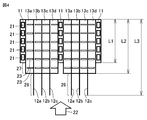
- FIG. 1 is a schematic diagram of a heat exchanger according to Embodiment 1 of the present invention.
- FIG. 2 is a partially enlarged perspective schematic view of region II in FIG.
- FIG. 3 is a schematic front view of a portion of the heat exchanger shown in FIG.
- the heat exchanger 1 shown in FIGS. 1 to 3 includes a plurality of heat transfer tubes 11 that are flat tubes, a plurality of plate fins 12 disposed between the heat transfer tubes 11, and the heat transfer tubes 11 and the plate fins 12.
- a corrugated fin 13 disposed between or between adjacent plate fins 12, and an upper header 2 and a lower header 3 respectively connected to an upper end and a lower end of a heat transfer tube 11 disposed along the direction of gravity.
- the main body 10 is constituted by the heat transfer tube 11, the plate fin 12 and the corrugated fin 13.
- the heat transfer tube 11 is provided so as to extend along a first direction that is a direction along the direction of gravity.
- a refrigerant circulates inside the heat transfer tube 11. Inside the heat transfer tube 11 having a flat tubular shape, a number of refrigerant flow paths may be formed along the extending direction (first direction).
- the plurality of heat transfer tubes 11 are arranged at intervals in a second direction indicated by an arrow 16 which is a direction intersecting the first direction so as to have a predetermined pitch P1 as shown in FIG.
- first to third plate fins 12 a to 12 c are arranged between adjacent heat transfer tubes 11.
- first to fourth corrugated fins 13a to 13d are arranged.
- the configuration between adjacent heat transfer tubes 11 is basically the same.
- the heat exchanger 1 includes at least one heat transfer tube 11, a first plate fin 12a, a second plate fin 12b, and a third plate fin 12c.
- At least one heat transfer tube 11 extends in a first direction indicated by an arrow 15 that intersects the air flow direction.
- a refrigerant circulates inside the heat transfer tube 11.
- the first plate fin 12 a extends in the first direction indicated by the arrow 15.
- the first plate fins 12a are arranged with at least one heat transfer tube 11 and a first interval P21 in a second direction indicated by an arrow 16 perpendicular to the first direction.
- the second plate fin 12b extends in the first direction.
- the second plate fins 12b are arranged at a second interval P22 from the first plate fins 12a in the second direction indicated by the arrow 16.
- interval between the 2nd plate fin 12b and the 3rd plate fin 12c in a 2nd direction may be the same as the said 2nd space
- the interval between the heat transfer tube 11 adjacent to the third plate fin 12c and the third plate fin 12c may be the same as or different from the first interval P21.
- the first interval P21 and the second interval P22 may be the same or different.
- the first corrugated fin 13a is disposed between at least one heat transfer tube 11 and the first plate fin 12a.
- the second corrugated fin 13b is disposed between the first plate fin 12a and the second plate fin 12b.
- the third corrugated fin 13c is disposed between the second plate fin 12b and the third plate fin 12c.
- the fourth corrugated fin 13 d is disposed between the third plate fin 12 c and the other heat transfer tube 11.
- the first plate fins 12a and the first corrugated fins 13a are connected by a plurality of first connecting portions 24 arranged at a third interval P3 in the first direction indicated by the arrow 15.
- the first plate fins 12a and the second corrugated fins 13b are connected by a plurality of second connection portions 25 arranged with a fourth interval P4 in the first direction indicated by the arrow 15.
- the 1st corrugated fin 13a and the heat exchanger tube 11 are connected by the some connection part arrange
- the interval between the connection portions may be the same as the third interval P3.
- the second corrugated fin 13b and the second plate fin 12b are connected by a plurality of connecting portions arranged at intervals along the first direction.
- the interval between the connection portions may be the same as the fourth interval P4.
- the third interval P3 and the fourth interval P4 may be the same or different.
- the configuration of the connecting portion between the third and fourth corrugated fins 13c, 13d, the second and third plate fins 12b, 12c and the other heat transfer tubes 11 is basically the same as the first corrugated fin 13a.
- the third interval P3 and the fourth interval P4 are larger than the first interval P21 and the second interval P22. If it says from a different viewpoint, the 1st direction between the some connection part to which the corrugated fin 13 is connected with the plate fin 12 from the width
- the hydrophilicity of at least part of the surfaces of the first plate fins 12a, the second plate fins 12b, the third plate fins 12c, and the at least one heat transfer tube 11 is the first corrugate. It may be higher than the hydrophilicity of the surface of the fin 13a, the second corrugated fin 13b, the third and fourth corrugated fins 13c, 13d.
- the hydrophilicity of the surfaces of the plate fins 12, the corrugated fins 13, and the heat transfer tubes 11, for example changes the material of these members or forms a surface treatment layer having different hydrophilicity on the surface. It can be adjusted by an arbitrary method such as changing the surface roughness.
- the surface roughness of the plate fins 12 and the heat transfer tubes 11 may be larger than the surface roughness of the corrugated fins 13.
- a hydrophilic or hydrophobic surface treatment layer may be formed on any of the plate fins 12 and the heat transfer tubes 11 and the corrugated fins 13.
- the thickness W of at least one heat transfer tube 11 in the second direction indicated by the arrow 16 in FIG. 3 may be greater than the thickness of the first to third plate fins 12a to 12c. Good.
- the thickness of the first to third plate fins 12a to 12c may be larger than the thickness of the first to fourth corrugated fins 13a to 13d.
- the positions of the plurality of first connection portions 24 overlap the positions of the plurality of second connection portions 25 in the first direction indicated by the arrow 15.
- the position of the plurality of first connection parts 24 overlaps with the position of the plurality of second connection parts 25 when at least the first connection part 24 is viewed from the second direction. It means that a part overlaps the second connection part 25.
- the first and second corrugated fins are based on the first and second intervals P21 and P22 which are the widths of the regions where the first and second corrugated fins 13a and 13b are disposed.
- the third interval P3 and the fourth interval P4, which are the pitches of the plurality of connecting portions 24 and 25 connected to the first plate fin 12a, are increased by 13a and 13b.
- the third and fourth corrugated fins also have a pitch of the plurality of connecting portions with the plate fin 12 larger than the first and second intervals P21 and P22.
- the inclined portions 33 and 34 of the first and second corrugated fins 13a and 13b located between the connecting portions 24 and 25, and the inclined portions of the third and fourth corrugated fins 13c and 13d are the first. It can be tilted sufficiently with respect to the direction.
- the inclination angle of the inclined portions 33 and 34 with respect to the first direction may be 70 ° or less (in other words, the inclination angle of the inclined portions 33 and 34 with respect to the second direction is 20 ° or more).
- the inclination angle of the inclined portions 33 and 34 with respect to the first direction may be 60 ° or less, may be 50 ° or less, and may be 45 ° or less.
- the inclination angle of the inclined parts 33 and 34 with respect to the second direction may be 30 ° or more, 40 ° or more, or 45 ° or more.
- the heat exchanger 1 is arranged so that the first direction is the vertical direction, dew condensation water is generated in the inclined portions 33 and 34 inclined with respect to the first direction in the first and second corrugated fins 13a and 13b. It can easily flow downward. Similarly, the dew condensation water can easily flow downward in the inclined portions of the third and fourth corrugated fins 13c and 13d. Therefore, the drainage at the corrugated fins 13 in the heat exchanger 1 can be enhanced.
- the hydrophilicity of at least part of the surfaces of the first plate fins 12a, the second plate fins 12b, and the at least one heat transfer tube 11 is such that the first corrugated fins 13a and the second It is higher than the hydrophilicity of the surface of the corrugated fin 13b.
- dew condensation water can be easily moved from the surface of the 1st and 2nd corrugated fin 13a, 13b to the 1st and 2nd plate fin 12a, 12b or the surface of the heat exchanger tube 11.
- the dew condensation water which moved to the 1st and 2nd plate fins 12a and 12b or the heat exchanger tube 11 can move to the perpendicular downward direction easily, for example. For this reason, the drainage property in a heat exchanger can be improved.
- the thickness W of the at least one heat transfer tube 11 in the second direction indicated by the arrow 16 in FIG. 3 is thicker than the thickness of the first and second plate fins 12a and 12b.
- the thicknesses of the first and second plate fins 12a and 12b are thicker than the thicknesses of the first and second corrugated fins 13a and 13b.
- the first to third plate fins 12a to 12c are thicker than the first to fourth corrugated fins 13a to 13d, which are all the corrugated fins 13.
- the thickness of the plate fin 12 is thicker than the thickness of the corrugated fin 13, the strength of the plate fin 12 can be increased and the shape of the heat exchanger can be stabilized.
- the positions of the plurality of first connection parts 24 overlap the positions of the plurality of second connection parts 25 in the first direction.
- the second and third plate fins 13b and 13c the second corrugated fin 13b and the third corrugated fin 13c, or the third corrugated fin 13c and the fourth corrugated so as to sandwich each of them.
- the position of the connection portion between the fin 13d and the plate fin overlaps in the first direction. If it does in this way, the position of the connection part in the front and back in the plate fin 12 will overlap, and the shape of the plate fin 12 can be stabilized compared with the case where the position of the said connection part differs in the front and back.
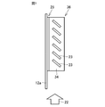
- FIG. 4 is a partial cross-sectional schematic diagram of a heat exchanger according to Embodiment 2 of the present invention.
- FIG. 4 corresponds to a partial schematic cross-sectional view of the heat exchanger in a plane perpendicular to the first direction shown in FIG.
- the heat exchanger shown in FIG. 4 has basically the same configuration as the heat exchanger shown in FIGS. 1 to 3, but the first to third plate fins 12a to 12c and the first to fourth The shape of the corrugated fins 13a to 13d is different from that of the heat exchanger shown in FIGS. Specifically, the width L2 of the first to fourth corrugated fins 13a to 13d is larger than the width L1 of the heat transfer tube 11 in the air flow direction indicated by the arrow 22.
- the first to fourth corrugated fins 13a to 13d include a portion 27 that protrudes from the heat transfer tube 11 toward the upstream side in the air flow direction.
- the width L3 of the first to third plate fins 12a to 12c is larger than the width L2 of the first to fourth corrugated fins 13a to 13d.
- the first to third plate fins 12a to 12c include a portion 26 protruding from the first to fourth corrugated fins 13a to 13d toward the upstream side in the air flow direction.
- the air flow direction is a direction perpendicular to the first direction and the second direction, and is indicated by an arrow 22 in FIG. Direction.
- the width L3 of the first and second plate fins 12a, 12b is larger than the width L2 of the first and second corrugated fins 13a, 13b.
- the width L3 of the first to third plate fins 12a to 12c which are a plurality of plate fins disposed between the two heat transfer tubes 11, is disposed adjacent to the plurality of plate fins. It is larger than the width L2 of the first to fourth corrugated fins 13a to 13d, which are a plurality of corrugated fins.
- the portions 26 of the first and second plate fins 12a and 12b protrude more upstream in the air flow direction than the first and second corrugated fins 13a and 13b.
- the third plate fin 12c includes a portion 26. That is, a portion 26 of the first to third plate fins 12a to 12c, which are a plurality of plate fins, is upstream of the first to fourth corrugated fins 13a to 13d, which are a plurality of corrugated fins, in the air flow direction. Protruding.
- the first and second corrugated fins 13 a, 13 b have a portion 27 that protrudes upstream from the at least one heat transfer tube 11 in the air flow direction. That is, a portion 27 of the first to fourth corrugated fins 13a to 13d, which is a plurality of corrugated fins, protrudes upstream from at least one heat transfer tube 11.
- a louver 23 is formed on the first to fourth corrugated fins 13a to 13d.
- the louver 23 is formed in inclined portions 33 and 34 (see FIG. 3) in the first to fourth corrugated fins 13a to 13d.
- the louver 23 is formed to extend linearly in a direction intersecting with the air flow direction, specifically, in a direction perpendicular to the air flow direction.
- the planar shape of the louver 23 is linear, but may be curved.
- the louver 23 cuts the inclined portions 33 and 34 of the first to fourth corrugated fins 13a to 13d, and inclines part of the inclined portions 33 and 34 adjacent to the cut with respect to other portions. It may be formed by causing to. Further, a slit as a simple opening may be formed in place of the louver 23.
- most of the condensed water is attached to the corrugated fins, whereas in the heat exchanger according to the present embodiment, most of the condensed water is the first to third plate fins 12a to 12a. 12c can be attached.
- the first to third plate fins 12a to 12c have a portion 26 that protrudes further to the windward side than the first to fourth corrugated fins 13a to 13d. Since there is no obstacle below the portion 26, the condensed water flows on the surface of the portion 26 of the first to third plate fins 12a to 12c and falls downward in a short time.
- the condensed water (moisture) condensed on the first to fourth corrugated fins 13a to 13d is guided downward by the louver 23 formed on the first to fourth corrugated fins 13a to 13d.
- the dew condensation water may not move sufficiently along the corrugated fin.
- the inclination of the inclined portions 33 and 34 of the first to fourth corrugated fins 13a to 13d with respect to the second direction is ensured, for example, by 20 ° or more. For this reason, dew condensation water can be easily moved downward along the inclined portions 33 and 34.
- the heat exchanger 1 can obtain the same effects as the heat exchanger in the first embodiment. Furthermore, in the heat exchanger 1, the width L3 of the first to third plate fins 12a to 12c, which are a plurality of plate fins arranged between the two heat transfer tubes 11, is adjacent to the plurality of plate fins. It is larger than the width L2 of the first to fourth corrugated fins 13a to 13d, which are a plurality of corrugated fins arranged in this manner.
- the first to third plate fins 12a to 12c include a portion 26 protruding from the first to fourth corrugated fins 13a to 13d in the air flow direction indicated by the arrow 22.
- the protruding portion 26 extends along the first direction, and can function as a drainage path for condensed water from the first to fourth corrugated fins 13a to 13d.
- the dew condensation water adheres at an early stage in the portions 26 of the first to third plate fins 12a to 12c protruding upstream in the air flow direction. Thereafter, the condensed water can be quickly moved below the first and second plate fins 12a and 12b via the portion 26 of the first and second plate fins 12a and 12b.
- FIG. 5 is a partial cross-sectional schematic diagram of a heat exchanger according to Embodiment 3 of the present invention.
- 6 is a partial perspective schematic view of the heat exchanger shown in FIG.
- FIG. 7 is a partial top schematic view of the heat exchanger shown in FIG.
- the heat exchanger shown in FIGS. 5 to 7 basically has the same configuration as that of the heat exchanger shown in FIG. 4, but the plate member 14 is disposed upstream of the heat transfer tube 11 in the air flow direction.
- the connection point and the arrangement of the louvers 23 are different from the heat exchanger shown in FIG.
- the plate member 14 is disposed so as to be connected to the windward end portion 28 that is the upstream side in the air flow direction in the heat transfer tube 11. ing.
- the plate member 14 may be a hollow member, for example, but may be a solid member.
- the width of the plate member 14 in the second direction (the direction indicated by the arrow 16 in FIG.
- the width of the first to fourth corrugated fins 13a to 13d may be the same as L2.
- the first to fourth corrugated fins 13a to 13d include inclined portions 33 and 34.
- a plurality of louvers 23 are formed in the inclined portions 33 and 34.
- the inclined portions 33 and 34 are inclined with respect to the first direction which is the vertical direction.
- a plurality of louvers 23 extending linearly are formed on the inclined portions 33 and 34.
- the plurality of louvers 23 are formed to extend downward in the vertical direction toward the upstream side in the air flow direction indicated by the arrow 22. That is, as shown in FIG. 6, the louver 23 in the inclined portion 33 is formed so as to approach the protruding portion apex 36 from the connecting portion 25 as it goes upstream in the air flow direction.
- the louver in the inclination part 34 is formed so that it may approach the connection part 25 from the protrusion part vertex 36 as it goes to the upstream of the distribution direction of air.
- the first direction is a direction along the direction of gravity.
- the 1st corrugated fin 13a is located between the some 1st connection parts 24 (refer FIG. 3), and contains the 1st inclination parts 33 and 34 inclined with respect to the perpendicular direction.
- the 2nd corrugated fin 13b is located between the some 2nd connection parts 25, and contains the 2nd inclination parts 33 and 34 inclined with respect to the perpendicular direction.
- At least one louver 23 extending linearly is formed on at least one of the first inclined portion and the second inclined portions 33 and 34. At least one louver 23 is formed to extend downward in the vertical direction as it goes upstream in the air flow direction indicated by arrow 22.
- the louver 23 is formed on all the inclined portions 33 and 34 of the first to fourth corrugated fins 13a to 13d, but may be formed only on some inclined portions 33 and 34. Further, it may be formed on a part of the first to fourth corrugated fins 13a to 13d.
- the heat exchanger 1 further includes a plate member 14 connected to a portion of the at least one heat transfer tube 11 located on the upstream side in the air flow direction.
- frost that has been attached to the heat transfer tube 11 in the past can be dispersed and attached to the plate member 14. For this reason, the amount of frost formation in the heat exchanger tube 11 can be reduced, and the drainage of the heat exchanger tube 11 can be improved as a result.
- louver 23 in the heat exchanger shown in FIGS. 5 to 7 is formed so as to extend downward in the vertical direction toward the upstream side in the air flow direction. Condensed water adhering to the surface can be guided upstream in the air flow direction. Since the portion 26 of the first to third plate fins 12a to 12c is arranged on the upstream side, the drainage of the heat exchanger can be improved by using the portion 26 as a drainage path.
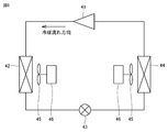
- FIG. 8 is a schematic diagram showing a refrigerant circuit of an air-conditioning apparatus according to Embodiment 4 of the present invention.
- the refrigerant circuit shown in FIG. 8 includes a compressor 41, a first heat exchanger 42 that acts as a condenser, a throttle device 43 that acts as an expansion valve, a second heat exchanger 44 that acts as an evaporator, and two blowers 45.
- the two blowers 45 are each driven by a blower motor 46.
- the two blowers 45 blow gas (for example, air) to either the first heat exchanger 42 or the second heat exchanger 44, respectively.
- the refrigerant circulates in the order of the compressor 41, the first heat exchanger 42, the expansion device 43, and the second heat exchanger 44.
- the air-conditioning apparatus shown in FIG. 8 includes a compressor 41, a first heat exchanger 42, a throttle device 43 as an expansion valve, and a second heat exchanger 44, and the refrigerant in which the refrigerant circulates. Provide a circuit.
- At least one of the first heat exchanger 42 and the second heat exchanger 44 shown in FIG. 8 is the heat exchanger described in any one of the first to third embodiments.
- the blower 45 blows gas to each heat exchanger along the third direction (the direction indicated by the arrow 22 in FIG. 4).
- the refrigerant flow direction in the first heat exchanger 42 and the second heat exchanger 44 in the refrigerant circuit is reversed from the direction shown in FIG.
- the exchanger may act as an evaporator and the second heat exchanger may act as a condenser.
- the air conditioner according to the present disclosure is a heat exchanger according to any of Embodiments 1 to 3 described above as a heat exchanger, it has sufficient drainage. Therefore, in the first and second heat exchangers 42 and 44, it is possible to suppress a decrease in efficiency and occurrence of problems due to insufficient discharge of condensed water.
- the present invention can be applied to an air conditioner, a refrigeration cycle apparatus, a heat pump apparatus, and the like.
Landscapes
- Engineering & Computer Science (AREA)
- Physics & Mathematics (AREA)
- Thermal Sciences (AREA)
- Mechanical Engineering (AREA)
- General Engineering & Computer Science (AREA)
- Geometry (AREA)
- Heat-Exchange Devices With Radiators And Conduit Assemblies (AREA)
Abstract
排水性を向上させた熱交換器を提供する。熱交換器において、第1のプレートフィン(12a)は、第1の方向に垂直な第2の方向において、少なくとも1つの伝熱管(11)と第1の間隔を隔てて配置される。第2のプレートフィン(12b)は、第2の方向において第1のプレートフィン(12a)と第2の間隔を隔てて配置される。第1のプレートフィン(12a)と第1のコルゲートフィン(13a)とは、第1の方向において第3の間隔を隔てて配置された複数の第1の接続部(24)により接続される。第1のプレートフィン(12a)と第2のコルゲートフィン(13b)とは、第1の方向において第4の間隔を隔てて配置された複数の第2の接続部(25)により接続される。第3の間隔および第4の間隔は、第1の間隔および第2の間隔より大きい。
Description
この発明は、熱交換器および空気調和装置に関し、より特定的にはコルゲートフィンを備える熱交換器および空気調和装置に関する。
従来、内部を冷媒が流通する伝熱管と、当該伝熱管に接続されたコルゲートフィンとを備える熱交換器が知られている(たとえば、特開平9-280754号公報参照)。
上述した熱交換器では、コルゲートフィンの表面に結露する結露水の排水性を確保するため、コルゲートフィンにルーバを形成する、あるいは伝熱管の表面に溝を形成する、といった対応がなされていた。しかし、このような対応のみでは、コルゲートフィンにおける十分な排水性を確保することは難しかった。
この発明の目的は、コルゲートフィンにおける排水性を向上させた熱交換器を提供することである。
本開示に従った熱交換器は、少なくとも1つの伝熱管と、第1のプレートフィンと、第2のプレートフィンと、第1のコルゲートフィンと、第2のコルゲートフィンとを備える。少なくとも1つの伝熱管は、空気の流通方向に対して交差する第1の方向に延在し、内部に冷媒が流通する。第1のプレートフィンは、第1の方向に延在する。第1のプレートフィンは、第1の方向に垂直な第2の方向において、少なくとも1つの伝熱管と第1の間隔を隔てて配置される。第2のプレートフィンは、第1の方向に延在する。第2のプレートフィンは、第2の方向において第1のプレートフィンと第2の間隔を隔てて配置される。第1のコルゲートフィンは、少なくとも1つの伝熱管と第1のプレートフィンとの間に配置される。第2のコルゲートフィンは、第1のプレートフィンと第2のプレートフィンとの間に配置される。第1のプレートフィンと第1のコルゲートフィンとは、第1の方向において第3の間隔を隔てて配置された複数の第1の接続部により接続される。第1のプレートフィンと第2のコルゲートフィンとは、第1の方向において第4の間隔を隔てて配置された複数の第2の接続部により接続される。第3の間隔および第4の間隔は、第1の間隔および第2の間隔より大きい。
本開示に従った空気調和装置は、圧縮機、第1熱交換器、膨張弁、および第2熱交換器を含み、冷媒が循環する冷媒回路を備える。第1熱交換器および第2熱交換器の少なくともいずれか一方が、上記熱交換器である。
上記によれば、第1および第2のコルゲートフィンにおいて第1または第2の接続部の間に位置する傾斜部の傾斜角度を大きくすることができるので、当該傾斜部を介した結露水の排水性を向上させることができる。
以下、図面を参照しながら本発明の実施の形態について説明する。以下の図面において同一または相当する部分には同一の参照番号を付し、その説明は繰り返さない。また、図1を含め、以下の図面では各構成部材の大きさの関係が実際のものとは異なる場合がある。さらに、明細書全文に表わされている構成要素の形態は、あくまでも例示であって、これらの記載に限定されるものではない。
実施の形態1.
<熱交換器の構成>
図1は、本発明の実施の形態1に係る熱交換器の模式図である。図2は、図1の領域IIにおける部分拡大斜視模式図である。図3は、図2に示した熱交換器の部分の正面模式図である。
<熱交換器の構成>
図1は、本発明の実施の形態1に係る熱交換器の模式図である。図2は、図1の領域IIにおける部分拡大斜視模式図である。図3は、図2に示した熱交換器の部分の正面模式図である。
図1~図3に示す熱交換器1は、扁平管である複数の伝熱管11と、当該伝熱管11の間に配置された複数のプレートフィン12と、伝熱管11とプレートフィン12との間、または隣接するプレートフィン12との間に配置されたコルゲートフィン13と、重力方向に沿って配置された伝熱管11の上端と下端とにそれぞれ接続された上ヘッダ2および下ヘッダ3とを備える。伝熱管11とプレートフィン12とコルゲートフィン13とから本体部10が構成される。伝熱管11は、重力方向に沿った方向である第1方向に沿って延びるように設けられている。伝熱管11の内部には冷媒が流通する。扁平管状の形状を有する伝熱管11の内部には、その延在方向(第1方向)に沿って復数の冷媒流路が形成されていてもよい。
複数の伝熱管11は、図3に示すように所定のピッチP1を有するように、第1の方向と交差する方向である矢印16で示す第2の方向に間隔を隔てて配置されている。図1~図3に示した熱交換器1では、隣接する伝熱管11の間に第1~第3のプレートフィン12a~12cを配置している。伝熱管11と第1~第3のプレートフィン12a~12cの間には、第1~第4のコルゲートフィン13a~13dが配置されている。隣接する伝熱管11の間の構成は基本的に共通である。
上述した熱交換器の構成を異なる観点から言えば、熱交換器1は、少なくとも1つの伝熱管11と、第1のプレートフィン12aと、第2のプレートフィン12bと、第3のプレートフィン12cと、第1のコルゲートフィン13aと、第2のコルゲートフィン13bと、第3および第4のコルゲートフィン13c、13dとを備える。少なくとも1つの伝熱管11は、空気の流通方向に対して交差する、矢印15で示す第1の方向に延在する。伝熱管11の内部には冷媒が流通する。第1のプレートフィン12aは、矢印15で示す第1の方向に延在する。第1のプレートフィン12aは、第1の方向に垂直な、矢印16で示す第2の方向において、少なくとも1つの伝熱管11と第1の間隔P21を隔てて配置される。第2のプレートフィン12bは、第1の方向に延在する。第2のプレートフィン12bは、矢印16で示す第2の方向において第1のプレートフィン12aと第2の間隔P22を隔てて配置される。なお、第2の方向における第2のプレートフィン12bと第3のプレートフィン12cとの間の間隔は、上記第2の間隔P22と同じでもよいし、異なっていてもよい。また、第3のプレートフィン12cに隣接する伝熱管11と当該第3のプレートフィン12cとの間の間隔は、上記第1の間隔P21と同じでもよいし異なっていてもよい。また、上記第1の間隔P21と第2の間隔P22とは同じでもよいし異なっていてもよい。
第1のコルゲートフィン13aは、少なくとも1つの伝熱管11と第1のプレートフィン12aとの間に配置される。第2のコルゲートフィン13bは、第1のプレートフィン12aと第2のプレートフィン12bとの間に配置される。第3のコルゲートフィン13cは、第2のプレートフィン12bと第3のプレートフィン12cとの間に配置される。第4のコルゲートフィン13dは、第3のプレートフィン12cと他の伝熱管11との間に配置される。第1のプレートフィン12aと第1のコルゲートフィン13aとは、矢印15で示す第1の方向において第3の間隔P3を隔てて配置された複数の第1の接続部24により接続される。第1のプレートフィン12aと第2のコルゲートフィン13bとは、矢印15で示す第1の方向において第4の間隔P4を隔てて配置された複数の第2の接続部25により接続される。また、第1のコルゲートフィン13aと伝熱管11とは、第1の方向に沿って間隔を隔てて配置された複数の接続部により接続されている。当該接続部の間隔は、上記第3の間隔P3と同じでもよい。また、第2のコルゲートフィン13bと第2のプレートフィン12bとは、第1の方向に沿って間隔を隔てて配置された複数の接続部により接続されている。当該接続部の間隔は、上記第4の間隔P4と同じでもよい。上記第3の間隔P3と第4の間隔P4とは同じでもよいが異なっていてもよい。
また、第3および第4のコルゲートフィン13c、13dと、第2および第3のプレートフィン12b、12cおよび他の伝熱管11との接続部の構成は、基本的に上記第1のコルゲートフィン13aと伝熱管11および第1のプレートフィン12aとの接続部の構成と同様である。上記第3の間隔P3および第4の間隔P4は、第1の間隔P21および第2の間隔P22より大きい。異なる観点から言えば、第2の方向における伝熱管11と複数のプレートフィン12と間の空間の幅より、コルゲートフィン13がプレートフィン12と接続される複数の接続部の間の第1の方向における距離が大きくなっている。第1~第4のコルゲートフィン13a~13dの傾斜部33、34には、ルーバが形成されていてもよい。
上記熱交換器1において、第1のプレートフィン12a、第2のプレートフィン12b、第3のプレートフィン12c、および少なくとも1つの伝熱管11の表面の少なくとも一部の親水性は、第1のコルゲートフィン13a、第2のコルゲートフィン13b、第3および第4のコルゲートフィン13c、13dの表面の親水性より高くてもよい。このようにプレートフィン12、コルゲートフィン13、伝熱管11の表面における親水性は、たとえばこれらの部材の材質を変更する、または当該表面に異なる親水性を有する表面処理層を形成する、当該表面の表面粗さを変更する、といった任意の方法により調整することができる。たとえば、プレートフィン12および伝熱管11の表面粗さを、コルゲートフィン13の表面粗さより大きくしてもよい。あるいは、プレートフィン12および伝熱管11と、コルゲートフィン13とのいずれかに、親水性または疎水性の表面処理層を形成してもよい。
また、上記熱交換器1において、図3の矢印16で示す第2の方向における少なくとも1つの伝熱管11の厚さWは、第1~第3のプレートフィン12a~12cの厚さより厚くてもよい。第1~第3のプレートフィン12a~12cの厚さは、第1~第4のコルゲートフィン13a~13dの厚さより厚くてもよい。
上記熱交換器1では、矢印15で示す第1の方向において、複数の第1の接続部24の位置が、複数の第2の接続部25の位置と重なっている。ここで、複数の第1の接続部24の位置が、複数の第2の接続部25の位置と重なっているとは、第2の方向から見たときに、第1の接続部24の少なくとも一部が、第2の接続部25と重なっていることを意味する。
<熱交換器の作用効果>
本開示に従った熱交換器では、第1および第2のコルゲートフィン13a、13bが配置される領域の幅である第1および第2の間隔P21,P22より、第1および第2のコルゲートフィン13a、13bが第1のプレートフィン12aと接続される複数の接続部24、25のピッチである第3の間隔P3および第4の間隔P4を大きくしている。また、上記のように第3および第4のコルゲートフィンについても、プレートフィン12との複数の接続部のピッチは上記第1および第2の間隔P21、P22より大きくなっている。このため、当該接続部24、25の間に位置する第1および第2のコルゲートフィン13a、13bの傾斜部33、34、さらに第3および第4のコルゲートフィン13c、13dにおける傾斜部を第1の方向に対して十分に傾けることができる。
本開示に従った熱交換器では、第1および第2のコルゲートフィン13a、13bが配置される領域の幅である第1および第2の間隔P21,P22より、第1および第2のコルゲートフィン13a、13bが第1のプレートフィン12aと接続される複数の接続部24、25のピッチである第3の間隔P3および第4の間隔P4を大きくしている。また、上記のように第3および第4のコルゲートフィンについても、プレートフィン12との複数の接続部のピッチは上記第1および第2の間隔P21、P22より大きくなっている。このため、当該接続部24、25の間に位置する第1および第2のコルゲートフィン13a、13bの傾斜部33、34、さらに第3および第4のコルゲートフィン13c、13dにおける傾斜部を第1の方向に対して十分に傾けることができる。
たとえば、第1の方向に対する当該傾斜部33、34の傾き角を70°以下(異なる観点から言えば第2の方向に対する傾斜部33、34の傾き角を20°以上)としてもよい。第1の方向に対する当該傾斜部33、34の傾き角は、60°以下としてもよく、50°以下としてもよく、45°以下としてもよい。また異なる観点から言えば、第2の方向に対する傾斜部33、34の傾き角を30°以上としてもよく、40°以上としてもよく、45°以上としてもよい。第1の方向を鉛直方向とするように熱交換器1を配置すれば、第1および第2のコルゲートフィン13a、13bにおいて第1の方向に対して傾斜した傾斜部33、34において結露水が容易に下方へ流れることができる。また、第3および第4のコルゲートフィン13c、13dにおける傾斜部についても、同様に結露水を容易に下方へ流すことができる。したがって、熱交換器1におけるコルゲートフィン13での排水性を高めることができる。
また、上記熱交換器1において、第1のプレートフィン12a、第2のプレートフィン12b、および少なくとも1つの伝熱管11の表面の少なくとも一部の親水性が、第1のコルゲートフィン13aおよび第2のコルゲートフィン13bの表面の親水性より高くなっている。このため、第1および第2のコルゲートフィン13a、13bの表面から、第1および第2のプレートフィン12a、12bまたは伝熱管11表面へ容易に結露水を移動させることができる。そして、第1および第2のプレートフィン12a、12bまたは伝熱管11へ移動した結露水は、たとえば鉛直下向きの方向に容易に移動することができる。このため、熱交換器における排水性を高めることができる。
上記熱交換器1において、図3の矢印16で示す第2の方向における少なくとも1つの伝熱管11の厚さWは、第1および第2のプレートフィン12a、12bの厚さより厚い。第1および第2のプレートフィン12a、12bの厚さは、第1および第2のコルゲートフィン13a、13bの厚さより厚い。異なる観点から言えば、第1~第3のプレートフィン12a~12cの厚さが、すべてのコルゲートフィン13である第1~第4のコルゲートフィン13a~13dの厚さより厚くなっている。このように、プレートフィン12の厚さがコルゲートフィン13の厚さより厚くなっているので、プレートフィン12の強度を高めることができ、熱交換器の形状を安定させることができる。
上記熱交換器1では、第1の方向において、複数の第1の接続部24の位置が複数の第2の接続部25の位置と重なっている。また、第2および第3のプレートフィン13b、13cにおいても、それぞれを挟むように配置された第2のコルゲートフィン13bと第3のコルゲートフィン13c、または第3のコルゲートフィン13cと第4のコルゲートフィン13dのプレートフィンとの接続部の位置が、第1の方向において重なっている。このようにすれば、プレートフィン12における表裏面での接続部の位置が重なることで、当該接続部の位置が表裏面で異なる場合よりプレートフィン12の形状を安定させることができる。
実施の形態2.
<熱交換器の構成>
図4は、本発明の実施の形態2に係る熱交換器の部分断面模式図である。図4は、図3に示した第1の方向に垂直な面における熱交換器の部分断面模式図に対応する。
<熱交換器の構成>
図4は、本発明の実施の形態2に係る熱交換器の部分断面模式図である。図4は、図3に示した第1の方向に垂直な面における熱交換器の部分断面模式図に対応する。
図4に示した熱交換器は、基本的に図1~図3に示した熱交換器と同様の構成を備えるが、第1~第3のプレートフィン12a~12cおよび第1~第4のコルゲートフィン13a~13dの形状が図1~図3に示した熱交換器と異なっている。具体的には、矢印22に示す空気の流通方向における、伝熱管11の幅L1より第1~第4のコルゲートフィン13a~13dの幅L2が大きくなっている。また、第1~第4のコルゲートフィン13a~13dは、空気の流通方向の上流側に向けて伝熱管11より突出している一部分27を含む。さらに、空気の流通方向において、第1~第4のコルゲートフィン13a~13dの幅L2より第1~第3のプレートフィン12a~12cの幅L3が大きくなっている。また、第1~第3のプレートフィン12a~12cは、空気の流通方向の上流側に向けて第1~第4のコルゲートフィン13a~13dより突出している一部分26を含む。
上述した熱交換器の構成を異なる観点から言えば、上記熱交換器1において、空気の流通方向は、第1方向および第2方向に対して垂直な方向であり、図4の矢印22により示す方向である。空気の流通方向において、第1および第2のプレートフィン12a、12bの幅L3は第1および第2のコルゲートフィン13a、13bの幅L2より大きい。異なる観点から言えば、2つの伝熱管11の間に配置された複数のプレートフィンである第1~第3のプレートフィン12a~12cの幅L3は、当該複数のプレートフィンに隣接して配置された複数のコルゲートフィンである第1~第4のコルゲートフィン13a~13dの幅L2より大きい。
上記熱交換器1において、第1および第2のプレートフィン12a、12bの一部分26は、第1および第2のコルゲートフィン13a、13bよりも空気の流通方向における上流側に突出している。また、第3のプレートフィン12cも、同様に一部分26を含んでいる。すなわち、複数のプレートフィンである第1~第3のプレートフィン12a~12cの一部分26は、複数のコルゲートフィンである第1~第4のコルゲートフィン13a~13dよりも空気の流通方向における上流側に突出している。また、上記熱交換器1において、第1および第2のコルゲートフィン13a、13bの一部分27は、少なくとも1つの伝熱管11よりも空気の流通方向における上流側に突出している。つまり、複数のコルゲートフィンである第1~第4のコルゲートフィン13a~13dの一部分27は、少なくとも1つの伝熱管11より上流側に突出している。
また、第1~第4のコルゲートフィン13a~13dには、ルーバ23が形成されている。ルーバ23は、第1~第4のコルゲートフィン13a~13dにおける傾斜部33、34(図3参照)に形成されている。ルーバ23は、空気の流通方向に対して交差する方向、具体的には空気の流通方向に対して垂直な方向に線状に伸びるように形成されている。ルーバ23の平面形状は直線状であるが、曲線状であってもよい。ルーバ23は、たとえば第1~第4のコルゲートフィン13a~13dの傾斜部33、34に切込みを入れ、当該切込みに隣接する傾斜部33、34の一部を他の部分に対して傾斜するように引き起こすことで形成されてもよい。また、ルーバ23に替えて単純な開口部としてのスリットを形成してもよい。
<熱交換器の動作および作用効果>
上記熱交換器1が蒸発器として作用する場合を考える。この場合、伝熱管11内に形成された冷媒流路に低温の冷媒が流れる。このため、伝熱管11、伝熱管11と接合されている第1のコルゲートフィン13a、第1のコルゲートフィン13aに接合されているプレートフィン12a、プレートフィン12aに接合されている第2のコルゲートフィン13b、第2のコルゲートフィン13bに接合されている第2のプレートフィン12b、という順番で熱伝達される。そして、上記のように伝熱管11内に低温の冷媒が流れているため、熱交換器表面温度は、伝熱管11から離れるにつれて高くなる。
上記熱交換器1が蒸発器として作用する場合を考える。この場合、伝熱管11内に形成された冷媒流路に低温の冷媒が流れる。このため、伝熱管11、伝熱管11と接合されている第1のコルゲートフィン13a、第1のコルゲートフィン13aに接合されているプレートフィン12a、プレートフィン12aに接合されている第2のコルゲートフィン13b、第2のコルゲートフィン13bに接合されている第2のプレートフィン12b、という順番で熱伝達される。そして、上記のように伝熱管11内に低温の冷媒が流れているため、熱交換器表面温度は、伝熱管11から離れるにつれて高くなる。
熱交換器1に空気が供給されると、熱交換器1の風上側より空気が熱交換器1の伝熱管11、プレートフィン12、コルゲートフィン13により形成される隙間を通過する。この時、空気は風上に近い部分から順に熱交換し、温度が低下する。空気の温度が低下し、露点以下となると空気中の水分が結露し、結露水として熱交換器表面に付着する。ここで、熱交換器の伝熱管11からの距離が最も遠く温度の高い第1~第3のプレートフィン12a~12cより結露水が付着しはじめる。その後、第1~第4のコルゲートフィン13a~13d通過時に更に空気温度が低下し、第1~第4のコルゲートフィン13a~13dに結露水が付着していく。
従来の熱交換器は、結露水のほとんがコルゲートフィンに付着していたのに対して、本実施形態に係る熱交換器では、結露水の大部分を第1~第3のプレートフィン12a~12cに付着させることができる。第1~第3のプレートフィン12a~12cは、第1~第4のコルゲートフィン13a~13dよりも風上側に突出した一部分26を有している。当該一部分26には下方に障害物がないため、結露した水分は、短時間の間に第1~第3のプレートフィン12a~12cの一部分26の表面を流れて下方に落下する。
一方、第1~第4のコルゲートフィン13a~13d上に結露した結露水(水分)は、第1~第4のコルゲートフィン13a~13dに形成されたルーバ23により下方に導かれながら、コルゲートフィンの形状に沿って下方に落下する。従来のコルゲートフィンでは、コルゲートフィンのルーバが形成された表面部分の第1の方向に対する傾きが相対的に小さいため、結露水がコルゲートフィン伝いに十分移動できない場合があった。しかし、本実施の形態における熱交換器では、第2の方向に対する第1~第4のコルゲートフィン13a~13dの傾斜部33、34の傾きはたとえば20°以上確保されている。このため、当該傾斜部33、34を伝って結露水を下方へ向けて容易に移動させることができる。
上記熱交換器1では、実施の形態1における熱交換器と同様の効果を得ることができる。さらに、上記熱交換器1では、2つの伝熱管11の間に配置された複数のプレートフィンである第1~第3のプレートフィン12a~12cの幅L3は、当該複数のプレートフィンに隣接して配置された複数のコルゲートフィンである第1~第4のコルゲートフィン13a~13dの幅L2より大きい。
この場合、第1~第3のプレートフィン12a~12cは、矢印22に示す空気の流通方向において、第1~第4のコルゲートフィン13a~13dから突出した一部分26を含むことになる。この突出した一部分26は第1方向に沿って延び、第1~第4のコルゲートフィン13a~13dからの結露水の排水経路として機能することができる。
また、空気の流通方向における上流側に突出した第1~第3のプレートフィン12a~12cの一部分26において早期に結露水が付着する。その後、第1および第2のプレートフィン12a、12bの上記一部分26を介して当該結露水を速やかに第1および第2のプレートフィン12a、12bの下方に移動させることができる。
実施の形態3.
<熱交換器の構成>
図5は、本発明の実施の形態3に係る熱交換器の部分断面模式図である。図6は、図5に示した熱交換器の部分斜視模式図である。図7は、図6に示した熱交換器の部分上面模式図である。
<熱交換器の構成>
図5は、本発明の実施の形態3に係る熱交換器の部分断面模式図である。図6は、図5に示した熱交換器の部分斜視模式図である。図7は、図6に示した熱交換器の部分上面模式図である。
図5~図7に示した熱交換器は、基本的に図4に示した熱交換器と同様の構成を備えるが、伝熱管11における空気の流通方向での上流側に、プレート部材14が接続されている点、およびルーバ23の配置が図4に示した熱交換器と異なっている。具体的には、図5~図7に示した熱交換器では、伝熱管11において空気の流通方向での上流側である風上側の端部28に接続するように、プレート部材14が配置されている。プレート部材14は、たとえば中空の部材であってもよいが、中実な部材であってもよい。プレート部材14の第2方向(図3の矢印16で示す方向)における幅は、伝熱管11の幅W(図3参照)と同じでもよい。また、空気の流通方向における伝熱管11とプレート部材14との合計幅は、第1~第3のプレートフィン12a~12cの幅L3と同じである。なお、伝熱管11とプレート部材14との合計幅は、第1~第3のプレートフィン12a~12cの幅L3と異なっていてもよく、たとえば第1~第4のコルゲートフィン13a~13dの幅L2と同じにしてもよい。
また、第1~第4のコルゲートフィン13a~13dは、傾斜部33、34を含む。当該傾斜部33、34には複数のルーバ23が形成されている。傾斜部33、34は、鉛直方向である第1の方向に対して傾斜している。傾斜部33、34には、線状に延びる複数のルーバ23が形成される。複数のルーバ23は、矢印22で示す空気の流通方向における上流側に向かうにつれて、鉛直方向下向きに延びるように形成されている。つまり、図6に示すように、傾斜部33におけるルーバ23は、空気の流通方向の上流側に向かうにつれて、接続部25から突出部頂点36に近づくように形成されている。また、図示していないが、傾斜部34におけるルーバは、空気の流通方向の上流側に向かうにつれて、突出部頂点36から接続部25に近づくように形成されている。
異なる観点から言えば、上記熱交換器1において、第1の方向は重力方向に沿った方向である。第1のコルゲートフィン13aは、複数の第1の接続部24(図3参照)の間に位置し、鉛直方向に対して傾斜した第1の傾斜部33、34を含む。第2のコルゲートフィン13bは、複数の第2の接続部25の間に位置し、鉛直方向に対して傾斜した第2の傾斜部33、34を含む。第1の傾斜部および第2の傾斜部33、34の少なくともいずれか一方には、線状に延びる少なくとも1つのルーバ23が形成される。少なくとも1つのルーバ23は、矢印22で示す空気の流通方向における上流側に向かうにつれて、鉛直方向下向きに延びるように形成されている。
なお、ルーバ23は第1~第4のコルゲートフィン13a~13dのすべての傾斜部33、34に形成されているが、一部の傾斜部33、34のみに形成されていてもよい。また、第1~第4のコルゲートフィン13a~13dのうちの一部に形成されていてもよい。
<熱交換器の作用効果>
上記熱交換器1では、実施の形態2における熱交換器と同様の効果を得ることができる。さらに、上記熱交換器1は、少なくとも1つの伝熱管11において、空気の流通方向における上流側に位置する部分に接続されたプレート部材14をさらに備えている。このようなプレート部材14を伝熱管11に接続することで、従来であれば伝熱管11に付着していた霜をプレート部材14に分散して付着させることができる。このため、伝熱管11での着霜量を低減し、結果的に伝熱管11の排水性を向上させることができる。
上記熱交換器1では、実施の形態2における熱交換器と同様の効果を得ることができる。さらに、上記熱交換器1は、少なくとも1つの伝熱管11において、空気の流通方向における上流側に位置する部分に接続されたプレート部材14をさらに備えている。このようなプレート部材14を伝熱管11に接続することで、従来であれば伝熱管11に付着していた霜をプレート部材14に分散して付着させることができる。このため、伝熱管11での着霜量を低減し、結果的に伝熱管11の排水性を向上させることができる。
また、図5~図7に示した熱交換器におけるルーバ23は、空気の流通方向における上流側に向かうにつれて、鉛直方向下向きに延びるように形成されているので、当該ルーバ23を介してコルゲートフィンの表面に付着した結露水を空気の流通方向の上流側に導くことができる。当該上流側では第1~第3のプレートフィン12a~12cの一部分26が配置されているため、当該一部分26を排水経路として利用することで熱交換器の排水性を向上させることができる。
実施の形態4.
<空気調和装置の構成>
図8は本発明の実施の形態4に係る空気調和装置の冷媒回路を示す模式図である。図8に示す冷媒回路は、圧縮機41、凝縮器として作用する第1熱交換器42、膨張弁として作用する絞り装置43、蒸発器として作用する第2熱交換器44、2つの送風機45を備える。2つの送風機45は、それぞれ送風機用モータ46により駆動される。2つの送風機45は、それぞれ第1熱交換器42または第2熱交換器44のいずれかに気体(たとえば空気)を吹き付ける。冷媒回路では、圧縮機41、第1熱交換器42、絞り装置43、第2熱交換器44の順番に冷媒が循環する。異なる観点から言えば、図8に示した空気調和装置は、圧縮機41、第1熱交換器42、膨張弁としての絞り装置43、および第2熱交換器44を含み、冷媒が循環する冷媒回路を備える。
<空気調和装置の構成>
図8は本発明の実施の形態4に係る空気調和装置の冷媒回路を示す模式図である。図8に示す冷媒回路は、圧縮機41、凝縮器として作用する第1熱交換器42、膨張弁として作用する絞り装置43、蒸発器として作用する第2熱交換器44、2つの送風機45を備える。2つの送風機45は、それぞれ送風機用モータ46により駆動される。2つの送風機45は、それぞれ第1熱交換器42または第2熱交換器44のいずれかに気体(たとえば空気)を吹き付ける。冷媒回路では、圧縮機41、第1熱交換器42、絞り装置43、第2熱交換器44の順番に冷媒が循環する。異なる観点から言えば、図8に示した空気調和装置は、圧縮機41、第1熱交換器42、膨張弁としての絞り装置43、および第2熱交換器44を含み、冷媒が循環する冷媒回路を備える。
図8に示した第1熱交換器42および第2熱交換器44の少なくともいずれか1つは、実施の形態1~実施の形態3のいずれかにおいて説明した熱交換器である。上記送風機45は、それぞれの熱交換器に対して第3方向(図4において矢印22で示す方向)に沿って気体を吹き付ける。なお、冷媒回路において四方弁などを配置することで、冷媒回路における第1熱交換器42および第2熱交換器44での冷媒の流通方向を図8に示した方向と逆にし、第1熱交換器を蒸発器として作用させ、第2熱交換器を凝縮器として作用させてもよい。
<空気調和装置の作用効果>
本開示に従った空気調和装置は、熱交換器として上述した実施の形態1~実施の形態3のいずれかに係る熱交換器であるため、十分な排水性を有している。そのため、第1および第2熱交換器42、44において結露水の排出が不十分となることによる効率の低下や不具合の発生を抑制できる。
本開示に従った空気調和装置は、熱交換器として上述した実施の形態1~実施の形態3のいずれかに係る熱交換器であるため、十分な排水性を有している。そのため、第1および第2熱交換器42、44において結露水の排出が不十分となることによる効率の低下や不具合の発生を抑制できる。
以上のように本発明の実施の形態について説明を行ったが、上述の実施の形態を様々に変形することも可能である。また、本発明の範囲は上述の実施の形態に限定されるものではない。本発明の範囲は、請求の範囲によって示され、請求の範囲と均等の意味および範囲内でのすべての変更を含むことが意図される。
本発明は、空気調和装置、冷凍サイクル装置、ヒートポンプ装置などに適用出来る。
1 熱交換器、2 上ヘッダ、3 下ヘッダ、10 本体部、11 伝熱管、12 プレートフィン、12a 第1のプレートフィン、12b 第2のプレートフィン、12c 第3のプレートフィン、13 コルゲートフィン、13a 第1のコルゲートフィン、13b 第2のコルゲートフィン、13c 第3のコルゲートフィン、13d 第4のコルゲートフィン、14 プレート部材、15,16,22 矢印、23 ルーバ、24 第1の接続部、25 第2の接続部、26,27 一部分、28 端部、33 第1の傾斜部、34 第2の傾斜部、36 突出部頂点、41 圧縮機、42 第1熱交換器、43 絞り装置、44 第2熱交換器、45 送風機、46 送風機用モータ。
Claims (10)
- 空気の流通方向に対して交差する第1の方向に延在し、内部に冷媒が流通する少なくとも1つの伝熱管と、
前記第1の方向に延在し、前記第1の方向に垂直な第2の方向において前記少なくとも1つの伝熱管と第1の間隔を隔てて配置された第1のプレートフィンと、
前記第1の方向に延在し、前記第2の方向において前記第1のプレートフィンと第2の間隔を隔てて配置された第2のプレートフィンと、
前記少なくとも1つの伝熱管と前記第1のプレートフィンとの間に配置された第1のコルゲートフィンと、
前記第1のプレートフィンと前記第2のプレートフィンとの間に配置された第2のコルゲートフィンとを備え、
前記第1のプレートフィンと前記第1のコルゲートフィンとは、前記第1の方向において第3の間隔を隔てて配置された複数の第1の接続部により接続され、
前記第1のプレートフィンと前記第2のコルゲートフィンとは、前記第1の方向において第4の間隔を隔てて配置された複数の第2の接続部により接続され、
前記第3の間隔および前記第4の間隔は、前記第1の間隔および前記第2の間隔より大きい、熱交換器。 - 前記空気の流通方向は、前記第1方向および前記第2方向に対して垂直な方向であり、
前記空気の流通方向において、前記第1および第2のプレートフィンの幅は前記第1および第2のコルゲートフィンの幅より大きい、請求項1に記載の熱交換器。 - 前記第1および第2のプレートフィンの一部分は、前記第1および第2のコルゲートフィンよりも前記空気の流通方向における上流側に突出している、請求項2に記載の熱交換器。
- 前記第1および第2のコルゲートフィンの一部分は、前記少なくとも1つの伝熱管よりも前記空気の流通方向における上流側に突出している、請求項3に記載の熱交換器。
- 前記少なくとも1つの伝熱管において、前記空気の流通方向における上流側に位置する部分に接続されたプレート部材をさらに備える、請求項2~請求項4のいずれか1項に記載の熱交換器。
- 前記第1の方向は重力方向に沿った方向であり、
前記第1のコルゲートフィンは、前記複数の第1の接続部の間に位置し、前記鉛直方向に対して傾斜した第1の傾斜部を含み、
前記第2のコルゲートフィンは、前記複数の第2の接続部の間に位置し、前記鉛直方向に対して傾斜した第2の傾斜部を含み、
前記第1の傾斜部および前記第2の傾斜部の少なくともいずれか一方には、線状に延びる少なくとも1つのルーバが形成され、
前記少なくとも1つのルーバは、前記空気の流通方向における上流側に向かうにつれて、前記鉛直方向下向きに延びるように形成されている、請求項1~請求項5のいずれか1項に記載の熱交換器。 - 前記第1のプレートフィン、前記第2のプレートフィン、および前記少なくとも1つの伝熱管の表面の少なくとも一部の疎水性は、前記第1のコルゲートフィンおよび前記第2のコルゲートフィンの表面の疎水性より高い、請求項1~請求項6のいずれか1項に記載の熱交換器。
- 前記第2の方向における前記少なくとも1つの伝熱管の厚さは、前記第1および第2のプレートフィンの厚さより厚く、
前記第1および第2のプレートフィンの前記厚さは、前記第1および第2のコルゲートフィンの厚さより厚い、請求項1~請求項7のいずれか1項に記載の熱交換器。 - 前記第1の方向において、前記複数の第1の接続部の位置は、前記複数の第2の接続部の位置と重なっている、請求項1~請求項8のいずれか1項に記載の熱交換器。
- 圧縮機、第1熱交換器、膨張弁、および第2熱交換器を含み、冷媒が循環する冷媒回路を備え、
前記第1熱交換器および前記第2熱交換器の少なくともいずれか一方が、請求項1~請求項9のいずれか1項に記載の熱交換器である、空気調和装置。
Priority Applications (3)
| Application Number | Priority Date | Filing Date | Title |
|---|---|---|---|
| JP2018553624A JP6997722B2 (ja) | 2016-12-02 | 2016-12-02 | 熱交換器および空気調和装置 |
| EP16922957.2A EP3550247B1 (en) | 2016-12-02 | 2016-12-02 | Heat exchanger and air conditioner |
| PCT/JP2016/085941 WO2018100738A1 (ja) | 2016-12-02 | 2016-12-02 | 熱交換器および空気調和装置 |
Applications Claiming Priority (1)
| Application Number | Priority Date | Filing Date | Title |
|---|---|---|---|
| PCT/JP2016/085941 WO2018100738A1 (ja) | 2016-12-02 | 2016-12-02 | 熱交換器および空気調和装置 |
Publications (1)
| Publication Number | Publication Date |
|---|---|
| WO2018100738A1 true WO2018100738A1 (ja) | 2018-06-07 |
Family
ID=62242355
Family Applications (1)
| Application Number | Title | Priority Date | Filing Date |
|---|---|---|---|
| PCT/JP2016/085941 Ceased WO2018100738A1 (ja) | 2016-12-02 | 2016-12-02 | 熱交換器および空気調和装置 |
Country Status (3)
| Country | Link |
|---|---|
| EP (1) | EP3550247B1 (ja) |
| JP (1) | JP6997722B2 (ja) |
| WO (1) | WO2018100738A1 (ja) |
Cited By (3)
| Publication number | Priority date | Publication date | Assignee | Title |
|---|---|---|---|---|
| WO2021234964A1 (ja) * | 2020-05-22 | 2021-11-25 | 三菱電機株式会社 | 熱交換器及び空気調和機 |
| EP3904808A4 (en) * | 2018-12-28 | 2022-09-21 | Danfoss A/S | HEAT EXCHANGER |
| EP3853478B1 (de) * | 2019-01-31 | 2024-11-27 | Hydac Cooling GmbH | Kühler |
Citations (8)
| Publication number | Priority date | Publication date | Assignee | Title |
|---|---|---|---|---|
| JPS5512375A (en) * | 1978-07-14 | 1980-01-28 | Nihon Radiator Co | Airrcooling evaporator |
| JPS6344076U (ja) * | 1986-09-03 | 1988-03-24 | ||
| JP2000234892A (ja) * | 1999-02-12 | 2000-08-29 | Zexel Corp | 熱交換器の縮小方法及びこの方法により製造される熱交換器 |
| JP2003336988A (ja) * | 2002-05-20 | 2003-11-28 | Japan Climate Systems Corp | 熱交換器 |
| JP2004150710A (ja) * | 2002-10-30 | 2004-05-27 | Denso Corp | 冷媒蒸発器およびその製造方法 |
| JP2005037002A (ja) * | 2003-07-16 | 2005-02-10 | Matsushita Electric Ind Co Ltd | 熱交換器 |
| JP2010025462A (ja) * | 2008-07-22 | 2010-02-04 | Nippon Light Metal Co Ltd | 熱交換器 |
| JP2010054115A (ja) * | 2008-08-28 | 2010-03-11 | Calsonic Kansei Corp | エバポレータ |
Family Cites Families (8)
| Publication number | Priority date | Publication date | Assignee | Title |
|---|---|---|---|---|
| JP3942210B2 (ja) * | 1996-04-16 | 2007-07-11 | 昭和電工株式会社 | 熱交換器、及びこの熱交換器を用いたルームエアコン並びにカーエアコン |
| JPH11108576A (ja) * | 1997-10-02 | 1999-04-23 | Nippon Light Metal Co Ltd | 熱交換器 |
| JP2004251554A (ja) | 2003-02-20 | 2004-09-09 | Matsushita Electric Ind Co Ltd | ヒートポンプ用室外熱交換器 |
| JP4503682B1 (ja) | 2009-04-22 | 2010-07-14 | シャープ株式会社 | 熱交換器及びそれを搭載した空気調和機 |
| FR2991034B1 (fr) * | 2012-05-25 | 2014-06-06 | Valeo Systemes Thermiques | Intercalaire pour echangeur thermique et echangeur thermique associe |
| JP2013250016A (ja) | 2012-06-01 | 2013-12-12 | Panasonic Corp | フィンチューブ熱交換器 |
| JP6289729B2 (ja) * | 2015-03-02 | 2018-03-07 | 三菱電機株式会社 | フィンアンドチューブ型熱交換器及びこれを備えた冷凍サイクル装置 |
| JP6165360B2 (ja) * | 2015-03-30 | 2017-07-19 | 三菱電機株式会社 | 熱交換器および空気調和機 |
-
2016
- 2016-12-02 EP EP16922957.2A patent/EP3550247B1/en active Active
- 2016-12-02 JP JP2018553624A patent/JP6997722B2/ja not_active Expired - Fee Related
- 2016-12-02 WO PCT/JP2016/085941 patent/WO2018100738A1/ja not_active Ceased
Patent Citations (8)
| Publication number | Priority date | Publication date | Assignee | Title |
|---|---|---|---|---|
| JPS5512375A (en) * | 1978-07-14 | 1980-01-28 | Nihon Radiator Co | Airrcooling evaporator |
| JPS6344076U (ja) * | 1986-09-03 | 1988-03-24 | ||
| JP2000234892A (ja) * | 1999-02-12 | 2000-08-29 | Zexel Corp | 熱交換器の縮小方法及びこの方法により製造される熱交換器 |
| JP2003336988A (ja) * | 2002-05-20 | 2003-11-28 | Japan Climate Systems Corp | 熱交換器 |
| JP2004150710A (ja) * | 2002-10-30 | 2004-05-27 | Denso Corp | 冷媒蒸発器およびその製造方法 |
| JP2005037002A (ja) * | 2003-07-16 | 2005-02-10 | Matsushita Electric Ind Co Ltd | 熱交換器 |
| JP2010025462A (ja) * | 2008-07-22 | 2010-02-04 | Nippon Light Metal Co Ltd | 熱交換器 |
| JP2010054115A (ja) * | 2008-08-28 | 2010-03-11 | Calsonic Kansei Corp | エバポレータ |
Cited By (5)
| Publication number | Priority date | Publication date | Assignee | Title |
|---|---|---|---|---|
| EP3904808A4 (en) * | 2018-12-28 | 2022-09-21 | Danfoss A/S | HEAT EXCHANGER |
| EP3853478B1 (de) * | 2019-01-31 | 2024-11-27 | Hydac Cooling GmbH | Kühler |
| WO2021234964A1 (ja) * | 2020-05-22 | 2021-11-25 | 三菱電機株式会社 | 熱交換器及び空気調和機 |
| JPWO2021234964A1 (ja) * | 2020-05-22 | 2021-11-25 | ||
| JP7292510B2 (ja) | 2020-05-22 | 2023-06-16 | 三菱電機株式会社 | 熱交換器及び空気調和機 |
Also Published As
| Publication number | Publication date |
|---|---|
| JP6997722B2 (ja) | 2022-01-18 |
| EP3550247B1 (en) | 2020-11-25 |
| EP3550247A1 (en) | 2019-10-09 |
| EP3550247A4 (en) | 2019-12-18 |
| JPWO2018100738A1 (ja) | 2019-10-17 |
Similar Documents
| Publication | Publication Date | Title |
|---|---|---|
| US9441890B2 (en) | Heat exchanger fin with corrugated portion and louvers | |
| EP2857785B1 (en) | Heat exchanger and air conditioner | |
| JP6165360B2 (ja) | 熱交換器および空気調和機 | |
| KR101451056B1 (ko) | 열교환기 및 공기 조화기 | |
| KR101451054B1 (ko) | 열교환기 및 공기 조화기 | |
| JP5934933B2 (ja) | 室外熱交換器 | |
| US8267160B2 (en) | Louvered plate fin | |
| JP6897372B2 (ja) | 熱交換器 | |
| WO2016194088A1 (ja) | 熱交換器及び冷凍サイクル装置 | |
| US11175053B2 (en) | Heat exchanger, refrigeration cycle device, and air-conditioning apparatus | |
| JP5084707B2 (ja) | 空気調和機 | |
| JP7660665B2 (ja) | 熱交換器および冷凍サイクル装置 | |
| JP2019190727A (ja) | 熱交換器 | |
| CN110462326B (zh) | 热交换器及制冷循环装置 | |
| WO2018100738A1 (ja) | 熱交換器および空気調和装置 | |
| JP6980117B2 (ja) | 熱交換器、熱交換器ユニット、及び冷凍サイクル装置 | |
| JP7006376B2 (ja) | 熱交換器 | |
| JP2010139115A (ja) | 熱交換器及び熱交換器ユニット | |
| WO2021130910A1 (ja) | 熱交換器ユニット及び冷凍サイクル装置 | |
| JPH10281674A (ja) | 室外機用クロスフィン熱交換器 | |
| JP2008025855A (ja) | 熱交換器、空気調和装置および熱交換器の製造方法 | |
| WO2025079135A1 (ja) | 熱交換器、冷凍サイクル装置および冷凍サイクルシステム | |
| JP6182429B2 (ja) | エバポレータ | |
| JPH11218368A (ja) | 冷媒蒸発器 | |
| WO2022054406A1 (ja) | 熱交換器及び空気調和装置 |
Legal Events
| Date | Code | Title | Description |
|---|---|---|---|
| 121 | Ep: the epo has been informed by wipo that ep was designated in this application |
Ref document number: 16922957 Country of ref document: EP Kind code of ref document: A1 |
|
| ENP | Entry into the national phase |
Ref document number: 2018553624 Country of ref document: JP Kind code of ref document: A |
|
| NENP | Non-entry into the national phase |
Ref country code: DE |
|
| ENP | Entry into the national phase |
Ref document number: 2016922957 Country of ref document: EP Effective date: 20190702 |