WO2018101143A1 - 吸引排出ユニット及び吸引排出装置 - Google Patents
吸引排出ユニット及び吸引排出装置 Download PDFInfo
- Publication number
- WO2018101143A1 WO2018101143A1 PCT/JP2017/041993 JP2017041993W WO2018101143A1 WO 2018101143 A1 WO2018101143 A1 WO 2018101143A1 JP 2017041993 W JP2017041993 W JP 2017041993W WO 2018101143 A1 WO2018101143 A1 WO 2018101143A1
- Authority
- WO
- WIPO (PCT)
- Prior art keywords
- chamber
- liquid
- suction
- pressure
- unit
- Prior art date
- Legal status (The legal status is an assumption and is not a legal conclusion. Google has not performed a legal analysis and makes no representation as to the accuracy of the status listed.)
- Ceased
Links
Images



Classifications
-
- A—HUMAN NECESSITIES
- A61—MEDICAL OR VETERINARY SCIENCE; HYGIENE
- A61M—DEVICES FOR INTRODUCING MEDIA INTO, OR ONTO, THE BODY; DEVICES FOR TRANSDUCING BODY MEDIA OR FOR TAKING MEDIA FROM THE BODY; DEVICES FOR PRODUCING OR ENDING SLEEP OR STUPOR
- A61M1/00—Suction or pumping devices for medical purposes; Devices for carrying-off, for treatment of, or for carrying-over, body-liquids; Drainage systems
- A61M1/60—Containers for suction drainage, adapted to be used with an external suction source
- A61M1/61—Two- or three-bottle systems for underwater drainage, e.g. for chest cavity drainage
-
- A—HUMAN NECESSITIES
- A61—MEDICAL OR VETERINARY SCIENCE; HYGIENE
- A61M—DEVICES FOR INTRODUCING MEDIA INTO, OR ONTO, THE BODY; DEVICES FOR TRANSDUCING BODY MEDIA OR FOR TAKING MEDIA FROM THE BODY; DEVICES FOR PRODUCING OR ENDING SLEEP OR STUPOR
- A61M1/00—Suction or pumping devices for medical purposes; Devices for carrying-off, for treatment of, or for carrying-over, body-liquids; Drainage systems
-
- A—HUMAN NECESSITIES
- A61—MEDICAL OR VETERINARY SCIENCE; HYGIENE
- A61M—DEVICES FOR INTRODUCING MEDIA INTO, OR ONTO, THE BODY; DEVICES FOR TRANSDUCING BODY MEDIA OR FOR TAKING MEDIA FROM THE BODY; DEVICES FOR PRODUCING OR ENDING SLEEP OR STUPOR
- A61M1/00—Suction or pumping devices for medical purposes; Devices for carrying-off, for treatment of, or for carrying-over, body-liquids; Drainage systems
- A61M1/60—Containers for suction drainage, adapted to be used with an external suction source
-
- A—HUMAN NECESSITIES
- A61—MEDICAL OR VETERINARY SCIENCE; HYGIENE
- A61M—DEVICES FOR INTRODUCING MEDIA INTO, OR ONTO, THE BODY; DEVICES FOR TRANSDUCING BODY MEDIA OR FOR TAKING MEDIA FROM THE BODY; DEVICES FOR PRODUCING OR ENDING SLEEP OR STUPOR
- A61M1/00—Suction or pumping devices for medical purposes; Devices for carrying-off, for treatment of, or for carrying-over, body-liquids; Drainage systems
- A61M1/71—Suction drainage systems
- A61M1/74—Suction control
-
- A—HUMAN NECESSITIES
- A61—MEDICAL OR VETERINARY SCIENCE; HYGIENE
- A61B—DIAGNOSIS; SURGERY; IDENTIFICATION
- A61B2217/00—General characteristics of surgical instruments
- A61B2217/002—Auxiliary appliance
- A61B2217/005—Auxiliary appliance with suction drainage system
-
- A—HUMAN NECESSITIES
- A61—MEDICAL OR VETERINARY SCIENCE; HYGIENE
- A61M—DEVICES FOR INTRODUCING MEDIA INTO, OR ONTO, THE BODY; DEVICES FOR TRANSDUCING BODY MEDIA OR FOR TAKING MEDIA FROM THE BODY; DEVICES FOR PRODUCING OR ENDING SLEEP OR STUPOR
- A61M2205/00—General characteristics of the apparatus
- A61M2205/33—Controlling, regulating or measuring
- A61M2205/3331—Pressure; Flow
- A61M2205/3341—Pressure; Flow stabilising pressure or flow to avoid excessive variation
-
- A—HUMAN NECESSITIES
- A61—MEDICAL OR VETERINARY SCIENCE; HYGIENE
- A61M—DEVICES FOR INTRODUCING MEDIA INTO, OR ONTO, THE BODY; DEVICES FOR TRANSDUCING BODY MEDIA OR FOR TAKING MEDIA FROM THE BODY; DEVICES FOR PRODUCING OR ENDING SLEEP OR STUPOR
- A61M2205/00—General characteristics of the apparatus
- A61M2205/33—Controlling, regulating or measuring
- A61M2205/3331—Pressure; Flow
- A61M2205/3348—Pressure measurement using a water column
-
- A—HUMAN NECESSITIES
- A61—MEDICAL OR VETERINARY SCIENCE; HYGIENE
- A61M—DEVICES FOR INTRODUCING MEDIA INTO, OR ONTO, THE BODY; DEVICES FOR TRANSDUCING BODY MEDIA OR FOR TAKING MEDIA FROM THE BODY; DEVICES FOR PRODUCING OR ENDING SLEEP OR STUPOR
- A61M2210/00—Anatomical parts of the body
- A61M2210/10—Trunk
Definitions
- the present invention relates to a suction / discharge unit and a suction / discharge device.
- a suction / discharge device that sucks body fluid and gas from a body cavity such as a chest of a subject after surgery using a suction pressure of a suction source that is operated continuously is known (for example, see Patent Document 1).
- a liquid such as a body fluid (hereinafter, body fluid or the like) sucked is stored in a transparent resin container (drainage container) called a suction bottle or a suction bag, and is removed from the suction source at an appropriate timing and discarded.
- These drainage containers isolate a downstream space where negative pressure is sucked by connecting a suction source and an upstream space into which body fluid or the like flows, and the space between both is sealed with sterile water. Used.
- the present invention has been made to solve the above-described problems, and an object of the present invention is to provide a suction discharge that can automatically prevent the negative pressure in the storage chamber and the first chamber from becoming excessively large. It is to provide a unit and a suction discharge device.
- An aspiration / discharge unit that solves the above problem is an aspiration / discharge unit disposed between a subject and an aspiration source, and communicates with the first connection hole that communicates with the subject and the aspiration source.
- a water sealing chamber having a first chamber and a second chamber separated from the first chamber by a water sealing portion and a second partition wall and connected to the suction source through the second connection hole;
- a negative pressure control unit that controls the pressure of the first chamber by flowing gas from the second chamber into the first chamber based on the pressure of the two chambers and the pressure of the first chamber.
- the pressure controller is arranged so that the second liquid can be stored and the pressure of the second chamber is applied to the second liquid.
- a control member having a control hole for controlling the inflow of the gas based on the surface tension of the second liquid, and the entire edge of the control member are attached to the inner periphery. And a first end.
- the second liquid when the negative pressure in the storage chamber becomes excessive, the second liquid is caused to flow through the control hole of the control member due to the pressure difference between the first chamber and the second chamber communicating with the storage chamber. It flows into the room 1 side.
- the inflowing second liquid is applied with the pressure of the first chamber and the pressure of the second chamber through the control hole. Therefore, due to the pressure difference between the first chamber and the second chamber, the gas in the second chamber flows into the first chamber side of the control member through the control hole and passes through the second liquid as bubbles. That is, the gas in the second chamber flows into the first chamber via the negative pressure control unit.
- the inflow of this gas reduces the negative pressure in the first chamber, that is, the storage chamber.
- the negative pressure control unit includes a first end part in which an entire edge part of the control member is attached to an inner periphery, and a second end part opened in the first chamber. And the first end portion has a support cylinder disposed in the liquid storage section, and the negative pressure control section includes the pressure in the first chamber and the second chamber accommodated in the support cylinder.
- the pressure of the storage chamber communicating with the first chamber is controlled to the hydraulic pressure generated by the weight of the second liquid and the pressure corresponding to the pressure of the second chamber. Can be made possible.
- the pressure of the storage chamber communicating with the first chamber is changed according to the diameter of the control hole, the density of the second liquid, the height, and the surface tension coefficient. It can be possible to control.
- the negative pressure control unit is accommodated in the second chamber. According to this configuration, by accommodating the negative pressure control unit in the second chamber, a pipe line or the like for flowing from the gas second chamber of the second chamber into the first chamber via the negative pressure control unit is externally provided. Therefore, it is possible to suppress an increase in the size of the suction / discharge unit.
- the suction / discharge unit includes a control unit that communicates with each of the first chamber and the second chamber and accommodates the negative pressure control unit. According to this configuration, the negative pressure in the storage chamber is reduced by connecting the control unit containing the negative pressure control unit to the unit having the storage chamber and the water seal chamber, and that the excessive negative pressure is generated. It becomes possible to confirm easily.
- the suction discharge unit has a filter between the storage chamber and the suction source. According to this configuration, it is possible to prevent bacteria from entering the connection tube from outside air by using a filter that does not allow bacteria to pass through.
- the suction / discharge unit has a second connection hole that communicates with the suction source, and communicates with the second chamber via a connecting pipe, and includes a pressure adjustment chamber that regulates the pressure of the second chamber. According to this configuration, after adjusting the pressure of the second chamber by the pressure adjusting chamber and reducing the pressure of the first chamber and the storage chamber and the excessive negative pressure during suction based on the pressure of the second chamber The pressure of the first chamber and the storage chamber can be set.
- the suction / discharge unit is provided in the negative pressure control unit, and the liquid stored on the first chamber side from the control member can flow into the liquid storage unit, and has a larger opening area than the control hole.
- the liquid stored in the support cylinder flows into the liquid reservoir through the fluid passage hole, and the negative pressure control unit is in the initial state. Reset to.
- the liquid is stored in the support cylinder, so that it can be confirmed that excessive negative pressure is generated again in the storage chamber by the stored liquid.
- the liquid passage hole is located at the same height as or lower than the control hole in the height direction. According to this configuration, the liquid stored on the control member flows into the liquid storage part from the liquid passage hole and does not remain on the control member.
- the suction / discharge unit includes a seal release member that is connected to or in contact with the valve body and can be operated so that the sealed state of the liquid passage hole by the valve body can be released. According to this configuration, it is possible to easily release the sealed state of the liquid passage hole by operating the valve body with the seal release member.
- the biasing member has elasticity, and the sealing release member elastically deforms the biasing member to release the sealing state of the control hole by the valve body.
- the valve body is urged in a direction to seal the liquid passage hole of the fixing member by the elastic force of the urging member, and the liquid passage hole is easily sealed. It becomes a stop state.
- Said suction discharge unit is a press member which cancels
- the suction / discharge unit is a separation member that releases the sealing state of the control hole by the valve body when the sealing release member separates the valve body from the control hole. According to this structure, the sealing state of the liquid passage hole of the fixing member can be easily released by operating the valve body with the seal releasing member that is the separating member.
- a suction / discharge device that solves the above problems includes any one of the suction / discharge units described above and a suction source connected to the suction / discharge unit.
- the negative pressure controller can automatically prevent the negative pressure in the storage chamber and the first chamber from becoming excessively large. Then, it is confirmed that an excessive negative pressure is generated in the storage chamber by the state of the negative pressure control unit (second liquid state).
- the suction / discharge unit and the suction / discharge device of the present invention it is possible to automatically prevent the negative pressure in the storage chamber and the first chamber from becoming excessively large.
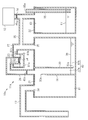
- FIG. 1 is a schematic cross-sectional view showing a suction / discharge device of a first embodiment.
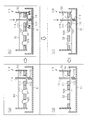
- (A)-(f) is a schematic sectional drawing which shows operation
- (A)-(d) is a schematic sectional drawing which shows operation
- the suction / discharge device 10 has a suction / discharge unit 11 and a suction pump 12 as a suction source.
- the suction / discharge unit 11 is connected to the subject via the connection tube 13.
- the distal end of the connection tube 13 is inserted into the chest cavity of a patient as a subject, for example.
- the suction / discharge unit 11 is connected to the suction pump 12 via a connection tube 13.
- the suction pump 12 generates a negative pressure inside the suction / discharge unit 11.
- the suction / discharge unit 11 includes a first unit 21 and a second unit 22.
- the first unit 21 and the second unit 22 are connected to each other by a connecting pipe 25.
- the suction pump 12 is connected to the connecting pipe 25 through the connecting pipe 14. Thereby, the suction pump 12 is connected to the first unit 21 and the second unit 22.
- the first unit 21 is formed in, for example, a box shape, and includes a bottom plate portion 31a, a side wall portion 31b, and a ceiling portion 31c.
- the side wall part 31b is formed in a cylindrical shape
- the bottom plate part 31a closes the lower end of the cylindrical side wall part 31b
- the ceiling part 31c closes the upper end of the cylindrical side wall part 31b.
- the material of the first unit 21 is made of a transparent material, such as transparent plastic, and the inside can be observed from the outside.
- the internal space of the first unit 21 is partitioned into a storage chamber 41 and a water seal chamber 42 by a first partition wall 32.
- the first partition wall 32 is connected to the bottom plate portion 31a and the side wall portion 31b, and the upper end 32a is separated from the ceiling portion 31c. Accordingly, the storage chamber 41 and the water sealing chamber 42 communicate with each other in the upper part of the first unit 21, and gas can move between the storage chamber 41 and the water sealing chamber 42.
- a first connection hole 34 that connects the storage chamber 41 and the outside of the unit is formed in the ceiling portion 31c.
- the connection tube 13 is connected to the first connection hole 34.
- the connection tube 13 is connected to a connection pipe (not shown) formed on the upper surface of the first unit 21.
- the first connection hole 34 communicates the inside of the storage chamber 41 and the inside of the connection tube 13, that is, the chest cavity of the subject.
- the water seal chamber 42 is divided into a first chamber 42 a and a second chamber 42 b by the second partition wall 33.
- the second partition wall 33 is connected to the ceiling portion 31c and the side wall portion 31b, and the lower end 33a is separated from the bottom plate portion 31a. Accordingly, the first chamber 42 a and the second chamber 42 b communicate with each other at the lower part of the first unit 21.
- the internal space of the first unit 21 is partitioned into a storage chamber 41 and a water seal chamber 42 by the first partition wall 32.
- the water sealing chamber 42 is divided into a first chamber 42 a and a second chamber 42 b by the second partition wall 33.
- a second connection hole 35 is formed in the ceiling portion 31c to communicate the second chamber 42b with the outside of the unit.
- the connecting pipe 25 is connected to the second connection hole 35.
- the connecting pipe 25 is connected to a connecting pipe (not shown) formed on the upper surface of the first unit 21.
- the second connection hole 35 allows the inside of the second chamber 42b and the inside of the connecting pipe 25 to communicate with each other.
- a filter 45a is disposed in the connecting pipe 14.
- the filter 45a is a hydrophobic filter.
- the filter 45a passes gas and does not pass liquid. Accordingly, the filter 45a prevents liquid from entering the suction pump 12 as a suction source.
- the filter 45b is disposed in the connecting pipe 25.
- the filter 45b is a bacterial filter that does not pass bacteria.
- the filter 45b is provided to prevent bacteria from entering the connection tube 13 from the outside air. Therefore, the filter 45b may be disposed on the outside air side with respect to the connection tube 13 and is disposed in the connecting pipe 25 in the present embodiment.
- sealing water 36 as a water sealing portion is accommodated.
- the sealing water 36 is aseptic water.
- the sealing water 36 may be colored. In the state where the suction pump 12 is not operating, the sealing water 36 is such that the water surface of the first chamber 42a and the water surface of the second chamber 42b are higher than the lower end 33a of the second partition wall 33, respectively. Stored in.
- the first unit 21 has a negative pressure control unit 50.
- the negative pressure control unit 50 is accommodated in the second chamber 42 b of the water seal chamber 42.
- the negative pressure control unit 50 includes a liquid storage unit 51, a control member 52, and a support cylinder 53.
- the liquid reservoir 51 is disposed at a predetermined position by a support member (not shown).
- the liquid reservoir 51 is fixed to a support cylinder 53 described later via a support member (not shown).
- the liquid reservoir 51 may be fixed by an inner wall of the second chamber 42b via a support member.
- the liquid storage part 51 is formed so that the liquid 54 can be stored.
- This liquid 54 is sterile water, similar to the sealing water 36 described above.
- the liquid 54 may be colored.
- a pressure inside the second chamber 42b is applied to the liquid 54.
- the liquid 54 stored in the liquid storage part 51 is supplied simultaneously with the sealing water 36 of the water sealing chamber 42, for example.
- the liquid 54 is supplied to the liquid storage unit 51.
- the liquid 54 overflowing from the liquid storage part 51 is stored as sealing water 36 in the water seal chamber 42.
- the control member 52 is formed in a plate shape.
- the control member 52 has a control hole 52X penetrating in the thickness direction (vertical direction in the drawing).
- the control hole 52X is formed in a predetermined shape.
- the control hole 52X is formed in, for example, a triangle or more polygon, circle, or ellipse.
- the control member 52 is appropriately formed to control the surface tension of the liquid 54 described above.
- the thickness of the control member 52 can be set to 20 ⁇ m, for example.
- the size of the control hole 52X can be set to 10 ⁇ m to 100 ⁇ m, for example, when it is circular.
- the control member 52 is fixed in the support cylinder 53.
- the control member 52 is supported in contact with the liquid 54 stored in the liquid storage unit 51.
- the control member 52 is fixed to the tip 53 a of the support cylinder 53, and the tip 53 a of the support cylinder 53 is disposed in the liquid storage unit 51.
- the tip 53 a of the support cylinder 53 is disposed in the liquid 54 stored in the liquid storage part 51.
- the base end 53 b of the support cylinder 53 is connected to the second partition wall 33.
- An opening 33b is formed in the second partition wall 33, and the inside of the first chamber 42a and the inside of the support cylinder 53 are communicated with each other through the opening 33b.
- the control member 52 is disposed between the first chamber 42a and the second chamber 42b by the support cylinder 53, and the liquid 54 stored in the liquid storage section 51 is disposed on the second chamber 42b side. Is done.
- the internal space of the second unit 22 functions as a pressure regulating chamber 43 that adjusts the pressure (negative pressure) inside the first unit 21.
- the second unit 22 is formed in a box shape, for example, and includes a bottom plate portion 61a, a side wall portion 61b, and a ceiling portion 61c.
- the side wall part 61b is formed in a cylindrical shape
- the bottom plate part 61a closes the lower end of the cylindrical side wall part 61b
- the ceiling part 61c closes the upper end of the cylindrical side wall part 61b.
- the material of the second unit 22 is made of a transparent material such as transparent plastic, and the inside can be observed from the outside.
- a third connection hole 63 that communicates the inside and the outside of the second unit 22 is formed in the ceiling portion 61 c of the second unit 22.
- the connecting pipe 25 is connected to the third connection hole 63.
- the connecting pipe 25 is connected to a connecting pipe (not shown) formed on the upper surface of the second unit 22.
- the third connection hole 63 communicates the inside of the second unit 22 and the inside of the connecting pipe 25 with each other.
- the inside of the second unit 22 communicates with the water-sealed chamber 42 (second chamber 42 b) of the first unit 21.
- the second unit 22 has a thin tube 65.
- the upper end of the thin tube 65 protrudes upward from the ceiling portion 61c, and the inside of the thin tube 65 is opened to the atmosphere by the opening 65a.
- the lower end of the thin tube 65 is located in the vicinity of the bottom plate portion 61a.
- the second unit 22 controls the pressure applied to the second chamber 42 b of the water seal chamber 42 according to the depth of the aseptic water 67.
- the suction / discharge device 10 When the inside of the second unit 22 is set to a negative pressure by the suction pump 12, the inside of the second unit 22 is maintained at a negative pressure corresponding to the height of the sterilized water 67.
- the internal space of the second unit 22 communicates with the inside of the first unit 21 and the second chamber 42 b of the water seal chamber 42 via the connecting pipe 25. Accordingly, the second unit 22 (pressure regulating chamber 43) adjusts the pressure inside the first unit 21.
- the second unit 22 (pressure regulating chamber 43) for example, adjusts the pressure in the second chamber 42b to a predetermined pressure (for example, ⁇ 10 hPa from atmospheric pressure).
- the level of the sealing water 36 in the second chamber 42b rises due to the negative pressure in the second chamber 42b, and the level of the sealing water 36 in the first chamber 42a falls.
- the storage chamber 41 has a predetermined negative pressure (for example, ⁇ 8 hPa from atmospheric pressure).
- the negative pressure in the storage chamber 41 is maintained by the suction pump 12 and the pressure adjusting chamber 43, and a suction force is applied to the chest cavity of the subject through the connection tube 13. Gases such as effluent and air are guided from the chest cavity of the subject to the storage chamber 41 via the connection tube 13, and the effluent is stored in the storage chamber 41.
- the gas passes through the lower end 33a of the second partition wall 33 from the first chamber 42a of the water-sealed chamber 42 communicating with the storage chamber 41, and reaches the second chamber 42b as bubbles in the sealing water 36.
- the negative pressure inside the storage chamber 41 may become excessive (for example, ⁇ 40 hPa from atmospheric pressure) due to factors such as coughing of the subject.
- the water level of the sealing water 36 in the first chamber 42a rises due to the negative pressure inside the storage chamber 41, and the water level in the second chamber 42b falls.
- the liquid 54 in the liquid storage unit 51 passes through the control member 52 based on the pressure difference between the pressure in the storage chamber 41 (first chamber 42 a) and the pressure in the second chamber 42 b. It flows into the support cylinder 53.
- the gas inside the second chamber 42 b flows into the support cylinder 53 through the control hole 52 ⁇ / b> X of the control member 52, and becomes a bubble 71 and passes through the liquid 54. That is, the negative pressure control unit 50 changes the gas inside the second chamber 42b to the first chamber 42a (storage chamber 41) based on the pressure in the first chamber 42a (storage chamber 41) and the pressure in the second chamber 42b. To pass. As described above, the gas supplied from the second chamber 42b to the storage chamber 41 through the first chamber 42a increases the pressure inside the storage chamber 41, and the excessive negative pressure is reduced.
- the negative pressure control unit 50 in an initial state (a state where the negative pressure of the storage chamber 41 shown in FIG. 1 is appropriate), the liquid 54 is stored in the liquid storage unit 51.
- the sum of the pressure in the first chamber 42a and the liquid pressure generated by the weight of the liquid 54 staying in the support cylinder 53 and the urinary surface tension on the surface generated by the control hole 52X in the liquid 54 is
- the pressure in the second chamber 42b becomes equal
- the inflow of gas from the second chamber 42b to the first chamber 42a stops.
- the surface tension generated by the control hole 52X in the liquid 54, and the pressure in the second chamber 42b the liquid 54 stays in the support cylinder 53.
- the control hole 52X has a circular shape.
- R be the diameter of the control hole 52X.
- the density of the liquid 54 is ⁇
- the surface tension coefficient of the liquid 54 is ⁇
- the height of the liquid 54 staying in the support cylinder 53 is h
- the acceleration of gravity is g.
- the pressure in the first chamber 42a is P1
- the pressure in the second chamber 42b is P2
- the pressure of the storage chamber 41 communicating with the first chamber 42a can be controlled to a pressure corresponding to the diameter R of the control hole 52X, the density ⁇ , the height h of the liquid 54, and the surface tension coefficient ⁇ .
- the suction / discharge device 10 includes a suction / discharge unit 11 and a suction pump 12.
- the suction / discharge unit 11 includes a first unit 21 and a second unit 22.
- the second unit 22 controls the pressure inside the first unit 21.
- the first unit 21 includes a storage chamber 41 and a water seal chamber 42, and the water seal chamber 42 is sealed from the first chamber 42 a by the first chamber 42 a communicating with the storage chamber 41 and the sealing water 36. Second chamber 42b.
- the negative pressure controller 50 is disposed in the second chamber 42b.
- the negative pressure control unit 50 includes a liquid storage unit that stores the liquid 54, a control member 52 having a control hole 52 ⁇ / b> X, and a support cylinder 53 that supports the control member 52.
- the liquid 54 is brought into the support cylinder 53 through the control hole 52X of the control member 52 due to the pressure difference between the first chamber 42a and the second chamber 42b communicating with the storage chamber 41.
- Inflow Pressure in the first chamber 42a is applied to the liquid 54 in the support cylinder 53 through the support cylinder 53, and pressure in the second chamber 42b is applied through the control hole 52X. Therefore, due to the pressure difference between the first chamber 42a and the second chamber 42b, the gas in the second chamber 42b flows into the support cylinder 53 through the control hole 52X, and becomes a bubble 71 and passes through the liquid 54. That is, the gas in the second chamber 42 b flows into the first chamber 42 a via the negative pressure control unit 50. By the inflow of this gas, the negative pressure in the first chamber 42a, that is, the storage chamber 41 can be reduced. In this way, it is possible to automatically prevent the negative pressure in the storage chamber 41 and the first chamber 42a from becoming excessively large.
- the negative pressure control unit 50 determines that the sum of the pressure in the first chamber 42a, the liquid pressure generated by the weight of the liquid 54 accommodated in the support cylinder 53, and the surface tension of the liquid 54 is the first value.
- the pressure in the second chamber 42b When the pressure is equal to the pressure in the second chamber 42b, the inflow of gas from the second chamber 42b to the first chamber 42a is stopped. For this reason, after eliminating the excessive negative pressure, the pressure of the storage chamber 41 communicating with the first chamber 42a is controlled to a pressure corresponding to the hydraulic pressure generated by the weight of the liquid 54 and the pressure of the second chamber 42b. Can do.
- the negative pressure control unit 50 is disposed in the second chamber 42b. For this reason, since it is not necessary to connect the pipe line etc. for making the gas of the 2nd chamber 42b flow into the 1st chamber 42a via the negative pressure control part 50 from the 2nd chamber 42b, the suction discharge unit 11 Increase in size can be suppressed.
- the first embodiment may be implemented in the following manner.
- the negative pressure control unit 50 is provided in the water seal chamber 42 (second chamber 42 b) of the first unit 21, but the negative pressure control unit 50 is provided outside the first unit 21. Also good.
- the suction / discharge unit 11 a of the suction / discharge device 10 a includes a first unit 21, a second unit 22, and a third unit 23.
- the first unit 21 includes a storage chamber 41 and a water seal chamber 42
- the water seal chamber 42 includes a first chamber 42a and a second chamber 42b.
- the second unit 22 communicates with the first unit 21 and is connected to the suction pump 12 to adjust the pressure of the first unit 21.
- the third unit 23 is formed, for example, in a box shape, and includes a bottom plate portion 81a, a side wall portion 81b, and a ceiling portion 81c.
- the material of the third unit 23 is made of a transparent material such as transparent plastic, and the inside can be observed from the outside.
- the liquid 54 is stored in the third unit 23.
- a cap (not shown) is provided on the ceiling of the third unit 23, and the cap 54 is opened and closed to store the liquid 54 in the third unit 23.
- a support cylinder 53 is inserted into the third unit 23 from the ceiling portion 81 c of the third unit 23, and a control member 52 is attached in the support cylinder 53. That is, the third unit 23 constitutes a negative pressure control unit.
- the support cylinder 53 communicates with the first chamber 42 a via the connection pipe 26 between the third unit 23 and the first unit 21.
- the inside of the third unit 23 is communicated with the second chamber 42 b through the connecting pipe 27 and the connecting pipe 25.
- the connection pipe 27 and the connection pipe 25 By the connection pipe 27 and the connection pipe 25, the pressure in the second chamber 42 b is applied to the liquid 54 stored in the liquid storage unit 51.
- a filter 45 b is disposed on the connection pipe 26.
- suction / discharge device 10a As in the suction / discharge device 10 of the above-described embodiment, it is possible to suppress an excessive negative pressure in the storage chamber 41 and the first chamber 42a. Further, it can be confirmed that an excessive negative pressure is generated according to the state of the liquid 54 in the third unit 23.
- the enlargement of the suction discharge apparatus 10a can be suppressed.
- the size of the unit increases due to pressure setting, which leads to an increase in size of the suction / discharge device.
- the thickness of the control member 52 that functions as a valve that controls the inflow of gas is, for example, 20 ⁇ m as described above. For this reason, compared with what uses a thin tube, the magnitude
- the negative pressure control part 50 of the said embodiment As shown in FIG. 6, in the suction / discharge unit 11b of the suction / discharge device 10b, the liquid 54 is stored in the liquid storage unit 51 of the negative pressure control unit 50.
- the control member 52 is attached to the end of the support cylinder 53 and supported so as to contact the liquid 54 stored in the liquid storage unit 51. Even if the control member 52 is supported in this manner, the same operations and effects as in the above embodiment can be obtained.
- the suction / discharge device 100 includes a suction / discharge unit 101 and a suction pump 12 as a suction source.
- the suction / discharge unit 101 is connected to the subject via the connection tube 13.
- the distal end of the connection tube 13 is inserted into the chest cavity of a patient as a subject, for example.
- the suction / discharge unit 101 is connected to the suction pump 12 via the connection tube 13.
- the suction pump 12 generates a negative pressure inside the suction / discharge unit 101.
- the suction / discharge unit 101 includes a first unit 21 and a second unit 22.
- the first unit 21 has a negative pressure control unit 110.
- the negative pressure control unit 110 is accommodated in the second chamber 42 b of the water seal chamber 42.
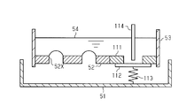
- the negative pressure control unit 110 includes a liquid storage unit 51, a control member 52, a support cylinder 53, a fixing member 111, a valve body 112, a biasing member 113, and a seal release member 114.
- the fixing member 111 is formed in a plate shape.
- the fixing member 111 has a liquid passage hole 111X penetrating in the thickness direction (vertical direction in the figure).
- the liquid passage hole 111X is formed in a predetermined shape.
- the fixing member 111 is disposed at the distal end 53a of the support cylinder 53. Further, the fixing member 111 is juxtaposed with the control member 52. The fixing member 111 is disposed with respect to the control member 52 so that the liquid passage hole 111X of the fixing member 111 is at a predetermined position.
- the fixing member 111 is configured such that the liquid passage hole 111X of the fixing member 111 is positioned at the same height as the control hole 52X of the control member 52 (the upper end of the liquid passage hole 111X and the upper end of the control hole 52X are the same height). It is arranged. That is, the fixing member 111 is disposed so that the upper surface of the fixing member 111 and the upper surface of the control member 52 are located at the same height.
- the fixing member 111 may be disposed so that the liquid passage hole 111X of the fixing member 111 is located at a lower height than the control hole 52X of the control member 52. That is, the fixing member 111 may be disposed such that the upper surface of the fixing member 111 is positioned at a lower level than the upper surface of the control member 52.
- the valve body 112 is disposed on the lower surface side of the fixing member 111.
- the valve body 112 is formed to be larger than the liquid passage hole 111X of the fixing member 111, and is sized to contact the lower surface of the fixing member 111 in the entire periphery of the liquid passage hole 111X in a top view.
- the valve body 112 seals the liquid passage hole 111 ⁇ / b> X of the fixing member 111 in a state where the valve body 112 is in contact with the lower surface of the fixing member 111.
- the valve body 112 is separated from the fixing member 111, the liquid passage hole 111X of the fixing member 111 is unlocked. That is, the valve body 112 can switch the liquid passage hole 111X of the fixing member 111 between a sealed state and an open state.
- the urging member 113 is disposed between the lower surface of the valve body 112 and the liquid reservoir 51.
- the urging member 113 has elasticity and urges the valve body 112 in a direction to close the liquid passage hole 111X of the fixing member 111.
- a compression spring can be used as this urging member 113.
- the seal release member 114 is disposed above the valve body 112.
- the seal release member 114 is formed in a bar shape extending in the vertical direction.
- the lower end of the seal release member 114 is disposed on the upper surface of the valve body 112, and the upper end of the seal release member 114 is first through an insertion hole 31 d formed in the ceiling portion 31 c of the first unit 21. Projecting to the outside of the unit 21.
- the seal release member 114 is formed integrally with the valve body 112.
- the suction pump 12 adjusts the internal pressure of the second chamber 42b of the first unit 21 to a predetermined pressure (for example, ⁇ 10 hPa from atmospheric pressure).
- a predetermined pressure for example, ⁇ 10 hPa from atmospheric pressure.
- the storage chamber 41 of the first unit 21 is set to a desired negative pressure (for example, ⁇ 8 hPa from atmospheric pressure).
- the negative pressure inside the storage chamber 41 may become excessive (for example, ⁇ 40 hPa from atmospheric pressure) due to factors such as coughing of the subject.
- the liquid 54 in the liquid reservoir 51 flows into the support cylinder 53 via the control member 52 based on the pressure difference between the pressure in the storage chamber 41 (first chamber 42a) and the pressure in the second chamber 42b.
- the gas inside the second chamber 42 b flows into the support cylinder 53 through the control hole 52 ⁇ / b> X of the control member 52, and becomes a bubble 71 and passes through the liquid 54.
- the negative pressure control unit 110 converts the gas inside the second chamber 42b into the first chamber 42a (storage chamber 41) based on the pressure in the first chamber 42a (storage chamber 41) and the pressure in the second chamber 42b. To pass. As described above, the gas supplied from the second chamber 42b to the storage chamber 41 through the first chamber 42a increases the pressure inside the storage chamber 41 and relieves excessive negative pressure.
- FIG. 8A shows a state in which the internal pressure of the storage chamber 41 (see FIG. 7) is reduced from an excessive negative pressure by the negative pressure control unit 110.
- the liquid 54 is stored on the upper side of the control member 52, that is, on the first chamber 42 a side (the storage chamber 41 side) from the control member 52.
- FIG. 8B when the medical worker manually pushes down the seal release member 114, the valve body 112 is pushed down by the seal release member 114, and the liquid passage hole 111X of the fixing member 111 is opened. It becomes an open state. Thereby, the stored liquid 54 flows into the liquid storage part 51 through the liquid passage hole 111X.
- the liquid passage hole 111X of the fixing member 111 is located at the same height as the control hole 52X of the control member 52, the liquid 54 disappears from the upper surface side of the control member 52 as shown in FIG. Then, as illustrated in FIG. 8D, when the medical worker releases his / her hand from the seal release member 114, the valve body 112 comes into close contact with the lower surface of the fixing member 111 by the biasing member 113. Thereby, the liquid passage hole 111X of the fixing member 111 is sealed by the valve body 112.
- the negative pressure control unit 110 is reset by the valve body 112, the fixing member 111, the urging member 113, and the sealing release member 114, that is, is in an initial state.
- the liquid 54 in the liquid storage portion 51 moves into the support cylinder 53 through the control hole 52 ⁇ / b> X of the control member 52 and is stored in the support cylinder 53. .
- the generation of excessive negative pressure can be confirmed by the liquid 54 thus stored.
- the sealing release member 114 is operated to push down the valve body 112 to open the liquid passage hole 111X of the fixing member 111, and the stored liquid 54 is caused to flow out to the liquid storage part 51, and
- the pressure control unit 110 is reset. In this way, by confirming the occurrence of excessive negative pressure and resetting the negative pressure control unit 110, it is possible to confirm the occurrence of excessive negative pressure after the confirmation.
- the negative pressure control unit 110 includes a liquid storage unit that stores the liquid 54, a control member 52 having a control hole 52X, and a support cylinder 53 that supports the control member 52. Further, the negative pressure control unit 110 seals the fixing member 111 having the fluid passage hole 111X, the valve body 112 that can switch the fluid passage hole 111X of the fixing member 111 to a sealed state or an open state, and the fluid passage hole 111X. And an urging member 113 for urging the valve body 112 in the stopping direction.
- the liquid 54 stored in the support cylinder 53 flows into the liquid storage part 51 through the liquid passage hole 111X, and the negative pressure control part 110 is Reset to the initial state.
- the liquid 54 is stored in the support cylinder 53. Therefore, it is confirmed that excessive negative pressure is generated again in the storage chamber 41 by the stored liquid 54. can do.
- the negative pressure control unit 110 has a seal release member 114 that releases the sealed state of the liquid passage hole 111X of the fixing member 111 by the valve body 112, that is, puts it into an open state.
- the liquid 54 stored in the support cylinder 53, that is, on the first chamber 42a (storage chamber 41) side from the control member 52 is caused to flow into the liquid storage portion 51, thereby negative pressure.
- the controller 110 can be easily reset to the initial state.
- the second embodiment may be implemented in the following manner. -You may change suitably each member contained in the negative pressure control part 110 of the said embodiment.
- the sealing release member 114 and the valve body 112 may be separate members.
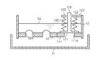
- the valve body 121 is disposed on the upper surface side of the fixing member 111.
- the urging member 122 is disposed above the fixed member 111 and between the support member 123 fixed to the support cylinder 53 and the valve body 121, and seals the valve body 121 in the liquid passage hole 111 ⁇ / b> X of the fixed member 111.
- the direction is stopped, that is, biased toward the fixing member 111.
- a compression spring can be used as the urging member 122.
- the seal release member 124 is fixed to the upper surface of the valve body 121. In FIG. 10, the valve body 121 and the seal release member 124 are shown integrally.
- the seal release member 124 By lifting the seal release member 124 upward and pulling the valve body 121 away from the fixing member 111, the liquid 54 stored on the first chamber 42 a side (see FIG. 7) from the control member 52 is allowed to flow through the fixing member 111. It flows into the liquid storage part 51 from 111X.
- the seal release member 124 functions as a separation member that separates the valve body 121 from the fixing member 111.
- sealing release member 124 and the valve body 121 may be separate members.
- the seal release member 124 and the valve body 121 may be integrated by press-fitting or using an adhesive or the like with respect to the insertion port formed at the lower end of the seal release member 124 in the valve body 121.
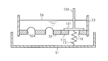
- the valve body 121 is disposed on the upper surface side of the fixing member 111.
- the urging member 131 is disposed between the lower surface of the valve body 121 and the liquid storage portion 51, and seals the liquid passage hole 111X of the fixing member 111, that is, the valve body 121 faces the upper surface of the fixing member 111.
- a tension spring can be used as this urging member 131.
- the seal release member 124 is fixed to the upper surface of the valve body 121.
- the valve body 121 and the sealing release member 124 are shown integrally. By lifting the seal release member 124 upward and pulling the valve body 121 away from the fixing member 111, the liquid 54 stored on the first chamber 42 a side (see FIG. 7) from the control member 52 is allowed to flow through the fixing member 111. It flows into the liquid storage part 51 from 111X.
- the seal release member 124 functions as a separation member that separates the valve body 121 from the fixing member 111.
- the valve body 112 is disposed on the lower surface side of the fixing member 111.
- the urging member 141 is disposed between the lower surface of the valve body 112 and the liquid storage portion 51, and seals the liquid passage hole 111 ⁇ / b> X of the fixing member 111, that is, the valve body 112 faces the upper surface of the fixing member 111.
- Energize As this urging member 141, for example, a member having elasticity such as rubber can be used, and it is fixed to the lower surface of the valve body 112. A hollow member such as a balloon can also be used as the urging member.
- the valve body 112 and the seal release member 114 are shown as separate members, but the valve body 112 and the seal release member 114 may be integrated.
- a pump capable of setting pressure may be used as the suction pump 12 and the second unit 22 may be omitted.
- the storage chamber 41 and the water sealing chamber 42 are formed as separate containers (units), and the first chamber 42a of the water sealing chamber 42 and the storage chamber 41 are connected to communicate with each other. Also good. Further, in the water sealing chamber 42, the first chamber 42a and the second chamber 42b may be formed as separate containers and connected so as to be separated by a sealing water 36 as a water sealing portion.
Landscapes
- Health & Medical Sciences (AREA)
- Heart & Thoracic Surgery (AREA)
- Biomedical Technology (AREA)
- Vascular Medicine (AREA)
- Engineering & Computer Science (AREA)
- Anesthesiology (AREA)
- Hematology (AREA)
- Life Sciences & Earth Sciences (AREA)
- Animal Behavior & Ethology (AREA)
- General Health & Medical Sciences (AREA)
- Public Health (AREA)
- Veterinary Medicine (AREA)
- Pulmonology (AREA)
- External Artificial Organs (AREA)
Abstract
吸引排出装置10の吸引排出ユニット11は、第1ユニット21と第2ユニット22とを有している。第2ユニット22は、第1ユニット21の内部の圧力を制御する。第1ユニット21は、貯蔵室41と水封室42とを有し、水封室42は、貯蔵室41と連通される第1室42aと、封止水36によって第1室42aと封止された第2室42bとを有している。第2室42bには陰圧制御部50が配設されている。陰圧制御部50は、液体54を貯留する液体貯留部と、制御孔52Xを有する制御部材52と、制御部材52を支持する支持筒53とを有している。陰圧制御部50は、第2室42bの圧力と第1室42aの圧力とに基づいて、制御孔52Xと液体54とを介して第2室42bから第1室42aへと気体を流入させて第1室42aの圧力を制御する。
Description
本発明は、吸引排出ユニット及び吸引排出装置に関する。
従来、持続的に運転する吸引源の吸引圧を用いて外科手術後の被検体の胸部等の体腔から体液やガスを吸引する吸引排出装置が知られている(例えば、特許文献1参照)。吸引された体液等の液体(以下、体液等)は、吸引ボトルや吸引バッグと呼ばれる透明の樹脂容器(排液容器)に貯蔵され、適時のタイミングで吸引源から取り外されて廃棄される。これらの排液容器は、吸引源が接続されて負圧吸引される下流側の空間と、体液等が流入する上流側の空間と、を隔離し、両空間の間を無菌水で水封して用いられる。
ところで、被検体が咳やくしゃみをしたとき、胸腔内、及び胸腔内と繋がる吸引排出装置の容器(貯蔵室)内の陰圧が過剰になることがある。このような陰圧は、被検体の体内の細胞組織にダメージを与える。そして、巡回する看護師等は、容器の陰圧を解除する操作を行う必要がある。
本発明は上記問題点を解決するためになされたものであって、その目的は、貯蔵室及び第1室内の陰圧が過剰に大きくなることを自動的に防止することを可能とした吸引排出ユニット及び吸引排出装置を提供することにある。
上記課題を解決する吸引排出ユニットは、被検体と吸引源との間に配設される吸引排出ユニットであって、前記被検体に連通される第1接続孔と、前記吸引源に連通される第2接続孔と、前記第1接続孔から流入する第1の液体を貯蔵する貯蔵室と、前記貯蔵室と連通されるとともに第1隔壁により前記第1の液体の流通が不能に隔てられた第1室と、前記第1室とは水封部及び第2隔壁によって隔てられ前記第2接続孔を介して前記吸引源と接続された第2室と、を有する水封室と、前記第2室の圧力と前記第1室の圧力とに基づいて前記第2室から前記第1室へ気体を流入させて前記第1室の圧力を制御する陰圧制御部と、を含み、前記陰圧制御部は、第2の液体を貯留可能とし、前記第2の液体に前記第2室の圧力が加わるように配設された液体貯留部と、前記第2の液体の表面張力に基づいて前記気体の流入を制御するための制御孔を有する制御部材と、前記制御部材の縁部の全体が内周に取着された第1端部と、を有する。
この構成によれば、貯蔵室の陰圧が過剰になると、貯蔵室に連通する第1室と第2室との圧力差によって第2の液体が制御部材の制御孔を介して制御部材の第1室側に流入する。その流入した第2の液体には、第1室の圧力が加わるとともに、制御孔を介して第2室の圧力が加わる。従って、第1室と第2室との圧力差によって、第2室の気体が制御孔を介して制御部材の第1室側に流入し、気泡となって第2の液体を通過する。つまり、第2室の気体が陰圧制御部を介して第1室へと流入する。この気体の流入によって、第1室、つまり貯蔵室の陰圧が軽減される。このように、貯蔵室及び第1室の陰圧が過剰に大きくなることを自動的に防止することができる。そして、制御孔における第2の液体の表面張力と第1室の圧力と第2室の圧力とのバランスによって、第1室と第2室との圧力差が所定値になると、第1室への気体の流入が停止し、第2の液体が制御部材の第1室側に貯留された状態となる。このように貯留する第2の液体により、貯蔵室に過剰な陰圧が生じたことが確認される。
上記の吸引排出ユニットにおいて、前記陰圧制御部は、前記制御部材の縁部の全体が内周に取着された第1端部と、前記第1室に開放された第2端部とを有し、前記第1端部が前記液体貯留部に配設された支持筒を有し、前記陰圧制御部は、前記第1室の圧力と、前記支持筒内に収容された前記第2の液体の重量により生じる液圧と、前記第2の液体の表面張力との和の値が前記第2室の圧力と等しいときに前記第2室から前記第1室への気体の流入を停止する。
この構成によれば、過剰な陰圧を解消したのち、第1室と連通する貯蔵室の圧力を、第2の液体の重量により生じる液圧と、第2室の圧力に応じた圧力に制御することを可能とすることができる。
上記の吸引排出ユニットにおいて、前記制御孔は円形状孔であり、前記第1室の圧力P1、前記第2室の圧力P2、前記第2の液体の密度ρ、重力加速度g、前記支持筒に貯留される前記第2の液体の高さh、前記第2の液体の表面張力係数σ、前記制御孔の直径Rについて、P1+ρgh+σ/R=P2の関係にあるときに前記第2室から前記第1室への気体の流入を停止する。
この構成によれば、過剰な陰圧を解消したのち、第1室と連通する貯蔵室の圧力を、制御孔の直径、第2の液体の密度、高さ、表面張力係数、に応じた圧力に制御することを可能とすることができる。
上記の吸引排出ユニットにおいて、前記陰圧制御部は、前記第2室に収容される。
この構成によれば、陰圧制御部を第2室に収容することで、第2室の気体第2室から陰圧制御部を介して第1室へと流入させるための管路等を外部に必要とせず、吸引排出ユニットの大型化を抑制することを可能とすることができる。
この構成によれば、陰圧制御部を第2室に収容することで、第2室の気体第2室から陰圧制御部を介して第1室へと流入させるための管路等を外部に必要とせず、吸引排出ユニットの大型化を抑制することを可能とすることができる。
上記の吸引排出ユニットは、前記第1室と前記第2室とにそれぞれ連通され、前記陰圧制御部を収容する制御ユニットを有する。
この構成によれば、貯蔵室と水封室とを有するユニットに陰圧制御部を収容した制御ユニットを接続することにより、貯蔵室における陰圧を低減し、過剰な陰圧が生じたことを容易に確認することができるようになる。
この構成によれば、貯蔵室と水封室とを有するユニットに陰圧制御部を収容した制御ユニットを接続することにより、貯蔵室における陰圧を低減し、過剰な陰圧が生じたことを容易に確認することができるようになる。
上記の吸引排出ユニットは、前記貯蔵室と前記吸引源との間に、フィルタを有する。
この構成によれば、フィルタに菌等を通過させないものを用いることで、外気から接続チューブへの菌の侵入を防ぐことができる。
この構成によれば、フィルタに菌等を通過させないものを用いることで、外気から接続チューブへの菌の侵入を防ぐことができる。
上記の吸引排出ユニットは、前記吸引源に連通される第2接続孔を有し、前記第2室と連結管を介して連通され、前記第2室の圧力を調整する圧力調整室を含む。
この構成によれば、圧力調整室により第2室の圧力を調整し、その第2室の圧力に基づいて、吸引時における第1室及び貯蔵室の圧力と、過剰な陰圧を低減した後の第1室及び貯蔵室の圧力を設定することができる。
この構成によれば、圧力調整室により第2室の圧力を調整し、その第2室の圧力に基づいて、吸引時における第1室及び貯蔵室の圧力と、過剰な陰圧を低減した後の第1室及び貯蔵室の圧力を設定することができる。
上記の吸引排出ユニットは、前記陰圧制御部に設けられ、前記制御部材より前記第1室側に貯留する液体が前記液体貯留部に流入可能であり、前記制御孔よりも開口面積が大きい通液孔と、前記通液孔を封止状態または開放状態に切り替え可能な弁体と、前記弁体に接続し前記弁体が前記通液孔を封止する方向に付勢する付勢部材と、を有する。
この構成によれば、弁体によって固定部材の通液孔を開放状態とすることで、支持筒に貯留した液体が通液孔を介して液体貯留部に流入し、陰圧制御部が初期状態にリセットされる。再び貯蔵室に過剰な陰圧が発生した場合には、液体が支持筒に貯留されるため、この貯留した液体によって、貯蔵室に過剰な陰圧が再度発生したことを確認することができる。
上記の吸引排出ユニットは、前記通液孔が高さ方向において、前記制御孔と同じ高さ又は低い高さに位置している。
この構成によれば、制御部材の上に貯留した液体は通液孔から液体貯留部へと流入して制御部材の上に残らない。
この構成によれば、制御部材の上に貯留した液体は通液孔から液体貯留部へと流入して制御部材の上に残らない。
上記の吸引排出ユニットは、前記弁体に接続又は接触し前記弁体による前記通液孔の封止状態を解除可能に操作しうる封止解除部材を有する。
この構成によれば、封止解除部材により弁体を操作して通液孔の封止状態を容易に解除することができる。
この構成によれば、封止解除部材により弁体を操作して通液孔の封止状態を容易に解除することができる。
上記の吸引排出ユニットは、前記付勢部材が弾性を有しており、前記封止解除部材が前記付勢部材を弾性変形させることで、前記弁体による前記制御孔の封止状態を解除する。
この構成によれば、封止解除部材の操作を停止すると、付勢部材の弾性力により弁体が固定部材の通液孔を封止する方向に付勢されてその通液孔を容易に封止状態となる。
この構成によれば、封止解除部材の操作を停止すると、付勢部材の弾性力により弁体が固定部材の通液孔を封止する方向に付勢されてその通液孔を容易に封止状態となる。
上記の吸引排出ユニットは、前記封止解除部材が前記弁体を押圧することで前記弁体による前記制御孔の封止状態を解除する押圧部材である。
この構成によれば、押圧部材である封止解除部材により弁体を操作することで固定部材の通液孔の封止状態を容易に解除することができる。
この構成によれば、押圧部材である封止解除部材により弁体を操作することで固定部材の通液孔の封止状態を容易に解除することができる。
上記の吸引排出ユニットは、前記封止解除部材が前記弁体を前記制御孔から引き離すことで前記弁体による前記制御孔の封止状態を解除する引離部材である。
この構成によれば、引離部材である封止解除部材により弁体を操作することで固定部材の通液孔の封止状態を容易に解除することができる。
この構成によれば、引離部材である封止解除部材により弁体を操作することで固定部材の通液孔の封止状態を容易に解除することができる。
上記課題を解決する吸引排出装置は、上記の何れかの吸引排出ユニットと、前記吸引排出ユニットに接続された吸引源と、を有する。
この構成によれば、陰圧制御部によって貯蔵室及び第1室の陰圧が過剰に大きくなることを自動的に防止される。そして、陰圧制御部の状態(第2の液体の状態)によって貯蔵室に過剰な陰圧が生じたことが確認される。
この構成によれば、陰圧制御部によって貯蔵室及び第1室の陰圧が過剰に大きくなることを自動的に防止される。そして、陰圧制御部の状態(第2の液体の状態)によって貯蔵室に過剰な陰圧が生じたことが確認される。
本発明の吸引排出ユニット及び吸引排出装置によれば、貯蔵室及び第1室内の陰圧が過剰に大きくなることを自動的に防止することができる。
以下、各形態を説明する。
なお、添付図面は、理解を容易にするために構成要素を拡大して示している場合がある。構成要素の寸法比率は実際のものと、または別の図面中のものと異なる場合がある。また、断面図では、理解を容易にするために、一部の構成要素のハッチングを省略している場合がある。
なお、添付図面は、理解を容易にするために構成要素を拡大して示している場合がある。構成要素の寸法比率は実際のものと、または別の図面中のものと異なる場合がある。また、断面図では、理解を容易にするために、一部の構成要素のハッチングを省略している場合がある。
(第1実施形態)
以下、第1実施形態を説明する。
図1に示すように、吸引排出装置10は、吸引排出ユニット11と、吸引源としての吸引ポンプ12とを有している。
以下、第1実施形態を説明する。
図1に示すように、吸引排出装置10は、吸引排出ユニット11と、吸引源としての吸引ポンプ12とを有している。
吸引排出ユニット11は、接続チューブ13を介して被検体に接続される。接続チューブ13の先端は、例えば被検体としての患者の胸腔内に挿入される。また、吸引排出ユニット11は、接続チューブ13を介して吸引ポンプ12と接続されている。吸引ポンプ12は、吸引排出ユニット11の内部に陰圧を発生する。
吸引排出ユニット11は、第1ユニット21と第2ユニット22とを有している。第1ユニット21と第2ユニット22は連結管25により互いに連結されている。本形態において、吸引ポンプ12は接続管14を介して連結管25に接続されている。これにより、吸引ポンプ12は、第1ユニット21及び第2ユニット22に接続される。
第1ユニット21は、例えば箱状に形成され、底板部31aと、側壁部31bと、天井部31cとを有している。本実施形態において、側壁部31bは筒状に形成され、底板部31aは、筒状の側壁部31bの下端を閉塞し、天井部31cは筒状の側壁部31bの上端を閉塞する。第1ユニット21の材料としては、透明材料、例えば透明プラスチックなどにより構成されており、外部から内部を観察することが可能である。
第1ユニット21の内部空間は、第1隔壁32によって貯蔵室41と水封室42とに区画されている。第1隔壁32は、底板部31aと側壁部31bとに接続されるとともに、上端32aが天井部31cから離間している。従って、貯蔵室41と水封室42は、第1ユニット21の上部において連通しており、貯蔵室41と水封室42との間で気体の移動が可能である。
貯蔵室41において、天井部31cには、貯蔵室41とユニット外部とを連通する第1接続孔34が形成されている。第1接続孔34には接続チューブ13が接続される。例えば、接続チューブ13は、第1ユニット21の上面に形成された接続管(図示略)に接続される。第1接続孔34は、貯蔵室41の内部と接続チューブ13の内部、つまり被検体の胸腔とを連通する。
水封室42は、第2隔壁33によって第1室42aと第2室42bとに区画されている。第2隔壁33は、天井部31cと側壁部31bとに接続されるとともに、下端33aが底板部31aから離間している。従って、第1室42aと第2室42bは、第1ユニット21の下部において連通している。
即ち、第1ユニット21の内部空間は、第1隔壁32によって貯蔵室41と水封室42とに区画されている。水封室42は、第2隔壁33によって第1室42aと第2室42bとに区画されている。
第2室42bにおいて、天井部31cには、第2室42bとユニット外部とを連通する第2接続孔35が形成されている。第2接続孔35には連結管25が接続される。例えば、連結管25は、第1ユニット21の上面に形成された接続管(図示略)に接続される。第2接続孔35は、第2室42bの内部と連結管25の内部とを互いに連通する。
接続管14には、フィルタ45aが配設されている。フィルタ45aは、疎水性のフィルタである。このフィルタ45aは、気体を通過し、液体を通過しない。従って、このフィルタ45aは、吸引源としての吸引ポンプ12に液体が入り込むのを防ぐ。
連結管25には、フィルタ45bが配設されている。フィルタ45bは、菌等を通過しない、バクテリアフィルタである。このフィルタ45bは、外気から接続チューブ13への菌の侵入を防ぐために設けられる。従って、フィルタ45bは、接続チューブ13より外気側に配設されればよく、本実施形態では、連結管25に配設されている。
水封室42には、水封部としての封止水36が収容される。封止水36は、無菌水である。なお、封止水36としては、着色がなされていてもよい。封止水36は、吸引ポンプ12が動作していない状態において、第1室42aの水面と第2室42bの水面とがそれぞれ第2隔壁33の下端33aよりも高くなるように水封室42に貯蔵される。
第1ユニット21は、陰圧制御部50を有している。本実施形態において、陰圧制御部50は、水封室42の第2室42bに収容されている。
陰圧制御部50は、液体貯留部51、制御部材52、支持筒53を有している。
陰圧制御部50は、液体貯留部51、制御部材52、支持筒53を有している。
液体貯留部51は、図示しない支持部材により所定の位置に配設されている。例えば、液体貯留部51は、図示しない支持部材を介して後述する支持筒53に固定される。なお、支持筒53に加えて第2室42bの内壁により支持部材を介して液体貯留部51を固定してもよい。液体貯留部51は、液体54を貯留可能に形成されている。この液体54は、上述の封止水36と同様に、無菌水である。なお、液体54としては、着色がなされていてもよい。この液体54には、第2室42bの内部の圧力が加わる。液体貯留部51に貯留される液体54は、例えば水封室42の封止水36と同時に供給される。例えば、液体貯留部51に対して液体54を供給する。液体貯留部51より溢れた液体54は、水封室42に封止水36として貯留される。
制御部材52は、板状に形成されている。制御部材52は、厚さ方向(図において上下方向)に貫通する制御孔52Xを有している。制御孔52Xは、所定の形状に形成されている。制御孔52Xは、例えば三角形以上の多角形、円形、楕円形に形成される。
制御部材52は、上述の液体54の表面張力を制御するために適宜形成される。制御部材52の厚さは、例えば20μmとすることができる。制御孔52Xの大きさは、例えば円形状とした場合、10μm~100μmとすることができる。
制御部材52は支持筒53内に固定されている。制御部材52は、液体貯留部51に貯留される液体54に接するように支持される。例えば、制御部材52は、支持筒53の先端53aに固定され、その支持筒53の先端53aは、液体貯留部51の中に配設されている。詳しくは、支持筒53の先端53aは、液体貯留部51に貯留される液体54内に配設される。
支持筒53の基端53bは、第2隔壁33に接続されている。その第2隔壁33には、開口33bが形成され、その開口33bにより第1室42aの内部と支持筒53の内部とが連通されている。つまり、支持筒53により、制御部材52は、第1室42aと第2室42bとの間に配設されるとともに、第2室42b側に液体貯留部51に貯留される液体54が配設される。
第2ユニット22の内部空間は、第1ユニット21の内部の圧力(陰圧)を調整する調圧室43として機能する。
第2ユニット22は、例えば箱状に形成され、底板部61aと、側壁部61bと、天井部61cとを有している。本実施形態において、側壁部61bは筒状に形成され、底板部61aは、筒状の側壁部61bの下端を閉塞し、天井部61cは筒状の側壁部61bの上端を閉塞する。第2ユニット22の材料としては、透明材料、例えば透明プラスチックなどにより構成されており、外部から内部を観察することが可能である。
第2ユニット22は、例えば箱状に形成され、底板部61aと、側壁部61bと、天井部61cとを有している。本実施形態において、側壁部61bは筒状に形成され、底板部61aは、筒状の側壁部61bの下端を閉塞し、天井部61cは筒状の側壁部61bの上端を閉塞する。第2ユニット22の材料としては、透明材料、例えば透明プラスチックなどにより構成されており、外部から内部を観察することが可能である。
第2ユニット22の天井部61cには、第2ユニット22の内部と外部とを連通する第3接続孔63が形成されている。第3接続孔63には、連結管25が接続される。例えば、連結管25は、第2ユニット22の上面に形成された接続管(図示略)に接続される。第3接続孔63は、第2ユニット22の内部と連結管25の内部とを互いに連通する。この連結管は、第2ユニット22の内部と第1ユニット21の水封室42(第2室42b)とが連通する。
第2ユニット22は、細管65を有している。本実施形態において、細管65の上端は天井部61cから上方に突出し、開口65aにより細管65の内部が大気開放されている。細管65の下端は底板部61aの近傍に位置している。第2ユニット22は、無菌水67の水深により、水封室42の第2室42bにかかる圧力を制御する。
(作用)
次に、上記の吸引排出装置10の作用を説明する。
吸引ポンプ12により第2ユニット22の内部を陰圧にすると、第2ユニット22の内部は無菌水67の水面の高さに応じた陰圧に保たれる。第2ユニット22の内部空間は、連結管25を介して第1ユニット21の内部、水封室42の第2室42bに連通されている。従って、第2ユニット22(調圧室43)は、第1ユニット21の内部の圧力を調整する。第2ユニット22(調圧室43)は、例えば第2室42bの圧力を所定の圧力(例えば、大気圧より-10hPa)に調整する。
次に、上記の吸引排出装置10の作用を説明する。
吸引ポンプ12により第2ユニット22の内部を陰圧にすると、第2ユニット22の内部は無菌水67の水面の高さに応じた陰圧に保たれる。第2ユニット22の内部空間は、連結管25を介して第1ユニット21の内部、水封室42の第2室42bに連通されている。従って、第2ユニット22(調圧室43)は、第1ユニット21の内部の圧力を調整する。第2ユニット22(調圧室43)は、例えば第2室42bの圧力を所定の圧力(例えば、大気圧より-10hPa)に調整する。
第1ユニット21において、第2室42bの陰圧によって第2室42bにおける封止水36の水位が上昇し、第1室42aにおける封止水36の水位が下降する。これにより、貯蔵室41が所定の陰圧(例えば、大気圧より-8hPa)となる。吸引ポンプ12と調圧室43とにより貯蔵室41の陰圧が保たれ、接続チューブ13を経て被検体の胸腔に吸引力が加えられる。そして、被検体の胸腔から接続チューブ13を介して排出液や空気等の気体が貯蔵室41へと導かれ、排出液は貯蔵室41に貯蔵される。気体は、貯蔵室41と連通する水封室42の第1室42aから第2隔壁33の下端33aをくぐりぬけて、封止水36内を気泡となって第2室42bへと到達する。
被検体の咳等の要因によって貯蔵室41の内部の陰圧が過剰(例えば、大気圧より-40hPa)になる場合がある。
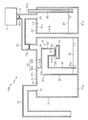
図2に示すように、貯蔵室41の内部の陰圧によって第1室42aにおける封止水36の水位が上昇し、第2室42bにおける水位が下降する。このとき、陰圧制御部50において、貯蔵室41(第1室42a)の圧力と第2室42bの圧力との差圧に基づいて、液体貯留部51の液体54が制御部材52を介して支持筒53に流入する。更に、第2室42bの内部の気体は、制御部材52の制御孔52Xを介して支持筒53内に流入し、気泡71となって液体54を通過する。つまり、陰圧制御部50は、第1室42a(貯蔵室41)の圧力と第2室42bの圧力とに基づいて、第2室42bの内部の気体を第1室42a(貯蔵室41)へ通過させる。このように、第2室42bから第1室42aを経て貯蔵室41に供給される気体により、貯蔵室41の内部の圧力が上昇し、過剰な陰圧が和らげられる。
図2に示すように、貯蔵室41の内部の陰圧によって第1室42aにおける封止水36の水位が上昇し、第2室42bにおける水位が下降する。このとき、陰圧制御部50において、貯蔵室41(第1室42a)の圧力と第2室42bの圧力との差圧に基づいて、液体貯留部51の液体54が制御部材52を介して支持筒53に流入する。更に、第2室42bの内部の気体は、制御部材52の制御孔52Xを介して支持筒53内に流入し、気泡71となって液体54を通過する。つまり、陰圧制御部50は、第1室42a(貯蔵室41)の圧力と第2室42bの圧力とに基づいて、第2室42bの内部の気体を第1室42a(貯蔵室41)へ通過させる。このように、第2室42bから第1室42aを経て貯蔵室41に供給される気体により、貯蔵室41の内部の圧力が上昇し、過剰な陰圧が和らげられる。
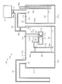
図3に示すように、貯蔵室41の内部の圧力が過剰な陰圧から低下すると、その圧力に応じて貯蔵室41と連通する第1室42aにおける封止水36の水位が下降する。このとき、支持筒53内の液体54には、支持筒53を介して第1室42aの圧力が加わるとともに、制御孔52Xを介して第2室42bの圧力が加わる。制御孔52Xにおける液体54の表面張力と第1室42aの圧力と第2室42bの圧力とのバランスによって、第1室42aと第2室42bとの圧力差が所定値になると、第1室への気体の流入が停止し、液体54が支持筒53内に貯留された状態となる。このように貯留する液体54により、貯蔵室41に過剰な陰圧が生じたことが確認される。
上記の陰圧制御部50における動作の詳細を説明する。
図4(a)に示すように、初期状態(図1に示す貯蔵室41の陰圧が適切な状態)においては、液体貯留部51に液体54が貯留されている。
図4(a)に示すように、初期状態(図1に示す貯蔵室41の陰圧が適切な状態)においては、液体貯留部51に液体54が貯留されている。
図2に示すように、貯蔵室41の陰圧が過剰になると、図4(b)に示すように、貯蔵室41と連通する第1室42aの陰圧により、液体貯留部51の液体54が制御部材52の制御孔52Xを介して支持筒53内に流れ込む。更に、図4(c)及び図4(d)に示すように、第2室42bの気体が制御孔52X内から支持筒53内に進入する。そして、図4(e)に示すように、気泡71となって液体54を通過する。
図3に示すように、第1室42aの圧力と支持筒53内に滞留する液体54の重量により生じる液圧と、液体54において制御孔52Xによって生じる表面における尿面張力との和の値は、第2室42bの圧力と等しくなると、第2室42bから第1室42aへの気体の流入が停止する。このとき、貯蔵室41及び第1室42aの圧力と、液体54において制御孔52Xによって生じる表面張力と、第2室42bの圧力とのバランスによって、液体54が支持筒53内に滞留する状態となる。
本実施形態において、制御孔52Xは円形状である。この制御孔52Xの直径をRとする。液体54の密度をρ、液体54の表面張力係数をσ、支持筒53に滞留する液体54の高さをh、重力加速度をgとする。そして、第1室42aの圧力をP1、第2室42bの圧力をP2とすると、図4(f)に示す状態では、
P1+ρgh+σ/R=P2
となる。従って、第1室42aと連通する貯蔵室41の圧力を、制御孔52Xの直径R、液体54の密度ρ、高さh、表面張力係数σ、に応じた圧力に制御することができる。
P1+ρgh+σ/R=P2
となる。従って、第1室42aと連通する貯蔵室41の圧力を、制御孔52Xの直径R、液体54の密度ρ、高さh、表面張力係数σ、に応じた圧力に制御することができる。
以上記述したように、本実施形態によれば、以下の効果を奏する。
(1-1)吸引排出装置10は、吸引排出ユニット11と吸引ポンプ12とを有している。吸引排出ユニット11は、第1ユニット21と第2ユニット22とを有している。第2ユニット22は、第1ユニット21の内部の圧力を制御する。第1ユニット21は、貯蔵室41と水封室42とを有し、水封室42は、貯蔵室41と連通される第1室42aと、封止水36によって第1室42aと封止された第2室42bとを有している。
(1-1)吸引排出装置10は、吸引排出ユニット11と吸引ポンプ12とを有している。吸引排出ユニット11は、第1ユニット21と第2ユニット22とを有している。第2ユニット22は、第1ユニット21の内部の圧力を制御する。第1ユニット21は、貯蔵室41と水封室42とを有し、水封室42は、貯蔵室41と連通される第1室42aと、封止水36によって第1室42aと封止された第2室42bとを有している。
第2室42bには陰圧制御部50が配設されている。陰圧制御部50は、液体54を貯留する液体貯留部と、制御孔52Xを有する制御部材52と、制御部材52を支持する支持筒53とを有している。
貯蔵室41の陰圧が過剰になると、貯蔵室41に連通する第1室42aと第2室42bとの圧力差によって液体54が制御部材52の制御孔52Xを介して支持筒53の内部に流入する。支持筒53内の液体54には、支持筒53を介して第1室42aの圧力が加わるとともに、制御孔52Xを介して第2室42bの圧力が加わる。従って、第1室42aと第2室42bとの圧力差によって、第2室42bの気体が制御孔52Xを介して支持筒53内に流入し、気泡71となって液体54を通過する。つまり、第2室42bの気体が陰圧制御部50を介して第1室42aへと流入する。この気体の流入によって、第1室42a、つまり貯蔵室41の陰圧を軽減することができる。このように、貯蔵室41及び第1室42aの陰圧が過剰に大きくなることを自動的に防止することができる。
制御孔52Xにおける液体54の表面張力と第1室42aの圧力と第2室42bの圧力とのバランスによって、第1室42aと第2室42bとの圧力差が所定値になると、第1室42aへの気体の流入が停止し、液体54が支持筒53内に貯留された状態となる。このように貯留する液体54により、貯蔵室41に過剰な陰圧が生じたことを確認することができる。
(1-2)陰圧制御部50は、第1室42aの圧力と、支持筒53内に収容された液体54の重量により生じる液圧と、液体54の表面張力との和の値が第2室42bの圧力と等しいときに第2室42bから第1室42aへの気体の流入を停止する。このため、過剰な陰圧を解消したのち、第1室42aと連通する貯蔵室41の圧力を、液体54の重量により生じる液圧と、第2室42bの圧力に応じた圧力に制御することができる。
(1-3)本実施形態において、陰圧制御部50は第2室42bに配設されている。このため、第2室42bの気体を第2室42bから陰圧制御部50を介して第1室42aへと流入させるための管路等を外部に接続する必要がないため、吸引排出ユニット11の大型化を抑制することができる。
(変形例)
上記第1実施形態は、以下の態様で実施してもよい。
・上記実施形態では、第1ユニット21の水封室42(第2室42b)に陰圧制御部50を内設したが、第1ユニット21の外部に陰圧制御部50を配設してもよい。
上記第1実施形態は、以下の態様で実施してもよい。
・上記実施形態では、第1ユニット21の水封室42(第2室42b)に陰圧制御部50を内設したが、第1ユニット21の外部に陰圧制御部50を配設してもよい。
図5に示すように、この吸引排出装置10aの吸引排出ユニット11aは、第1ユニット21、第2ユニット22、第3ユニット23を有している。第1ユニット21は、貯蔵室41と水封室42とを有し、水封室42は第1室42aと第2室42bとを有している。第2ユニット22は、第1ユニット21と連通されるとともに、吸引ポンプ12に接続され、第1ユニット21の圧力を調整する。
第3ユニット23は、例えば箱状に形成され、底板部81aと、側壁部81bと、天井部81cとを有している。第3ユニット23の材料としては、透明材料、例えば透明プラスチックなどにより構成されており、外部から内部を観察することが可能である。
第3ユニット23には液体54が貯留される。第3ユニット23の天井部に図示しないキャップが設けられ、そのキャップを開閉して液体54を第3ユニット23内に貯留する。第3ユニット23の天井部81cから第3ユニット23内に支持筒53が挿通され、その支持筒53内に制御部材52が取着されている。つまり、第3ユニット23は陰圧制御部を構成する。
支持筒53は、第3ユニット23と第1ユニット21との間の接続管26を介して第1室42aに連通されている。第3ユニット23の内部は、接続管27と連結管25を介して第2室42bに連通されている。この接続管27及び連結管25により、第2室42bの圧力が、液体貯留部51の貯留された液体54に加わる。この吸引排出ユニット11aでは、接続管26にフィルタ45bが配設されている。
この吸引排出装置10aにおいても上記実施形態の吸引排出装置10と同様に、貯蔵室41及び第1室42aの過剰な陰圧を抑制することができる。また、第3ユニット23における液体54の状態により、過剰な陰圧が発生したことを確認することができる。
そして、この第3ユニット23により、吸引排出装置10aの大型化を抑制することができる。例えば、第2ユニット22のように、細管を有するユニットにより、貯蔵室41及び第1室42aの過剰な陰圧を抑制することが考えられる。しかし、細管を有するユニットでは、圧力設定のためにユニットが大型化し、吸引排出装置の大型化を招く。これに対し、上述した第3ユニット23において、気体の流入を制御する弁として機能する制御部材52の厚さは、上述したように例えば20μmである。このため、細管を用いるものと比べ、第3ユニット23の大きさが小さい。このため、この第3ユニット23を第1ユニット21の外部に接続した吸引排出装置10aにおいて、大型化を抑制することができる。
・上記実施形態の陰圧制御部50の形状を適宜変更してもよい。
図6に示すように、この吸引排出装置10bの吸引排出ユニット11bにおいて、陰圧制御部50の液体貯留部51には液体54が貯留されている。そして、制御部材52は、支持筒53の端部に取着され、液体貯留部51に貯留された液体54に接するように支持される。このように制御部材52を支持するようにしても、上記実施形態と同様の作用及び効果を得ることができる。
図6に示すように、この吸引排出装置10bの吸引排出ユニット11bにおいて、陰圧制御部50の液体貯留部51には液体54が貯留されている。そして、制御部材52は、支持筒53の端部に取着され、液体貯留部51に貯留された液体54に接するように支持される。このように制御部材52を支持するようにしても、上記実施形態と同様の作用及び効果を得ることができる。
(第2実施形態)
以下、第2実施形態を説明する。
なお、この実施形態において、上記実施形態と同じ構成部材については同じ符号を付してその説明の一部又は全てを省略する。
以下、第2実施形態を説明する。
なお、この実施形態において、上記実施形態と同じ構成部材については同じ符号を付してその説明の一部又は全てを省略する。
図7に示すように、吸引排出装置100は、吸引排出ユニット101と、吸引源としての吸引ポンプ12とを有している。
吸引排出ユニット101は、接続チューブ13を介して被検体に接続される。接続チューブ13の先端は、例えば被検体としての患者の胸腔内に挿入される。また、吸引排出ユニット101は、接続チューブ13を介して吸引ポンプ12と接続されている。吸引ポンプ12は、吸引排出ユニット101の内部に陰圧を発生する。
吸引排出ユニット101は、接続チューブ13を介して被検体に接続される。接続チューブ13の先端は、例えば被検体としての患者の胸腔内に挿入される。また、吸引排出ユニット101は、接続チューブ13を介して吸引ポンプ12と接続されている。吸引ポンプ12は、吸引排出ユニット101の内部に陰圧を発生する。
吸引排出ユニット101は、第1ユニット21と第2ユニット22とを有している。
第1ユニット21は、陰圧制御部110を有している。本実施形態において、陰圧制御部110は、水封室42の第2室42bに収容されている。
第1ユニット21は、陰圧制御部110を有している。本実施形態において、陰圧制御部110は、水封室42の第2室42bに収容されている。
陰圧制御部110は、液体貯留部51、制御部材52、支持筒53、固定部材111、弁体112、付勢部材113、封止解除部材114を有している。
固定部材111は、板状に形成されている。固定部材111は、厚さ方向(図において上下方向)に貫通する通液孔111Xを有している。通液孔111Xは、所定の形状に形成されている。
固定部材111は、板状に形成されている。固定部材111は、厚さ方向(図において上下方向)に貫通する通液孔111Xを有している。通液孔111Xは、所定の形状に形成されている。
本実施形態において、固定部材111は、支持筒53の先端53aに、配設されている。また、固定部材111は、制御部材52と並設されている。固定部材111は、制御部材52に対して、固定部材111の通液孔111Xを所定の位置とするように配設されている。例えば、固定部材111は、固定部材111の通液孔111Xを制御部材52の制御孔52Xと同じ高さ(通液孔111Xの上端と制御孔52Xの上端とが同じ高さ)に位置するように配設されている。つまり、固定部材111は、固定部材111の上面と制御部材52の上面とが同じ高さに位置するように配設されている。
なお、固定部材111は、固定部材111の通液孔111Xを制御部材52の制御孔52Xより低い高さに位置するように配設されてもよい。つまり、固定部材111は、固定部材111の上面を制御部材52の上面より低い高さに位置するように配設されてもよい。
弁体112は、固定部材111の下面側に配設されている。弁体112は、固定部材111の通液孔111Xより大きく形成され、上面視において、通液孔111Xの周囲全体において固定部材111の下面と接する大きさに形成されている。弁体112は、弁体112が固定部材111の下面に接した状態で、固定部材111の通液孔111Xを封止する。弁体112が固定部材111から離間すると、固定部材111の通液孔111Xが開錠状態となる。つまり、弁体112は、固定部材111の通液孔111Xを、封止状態と開放状態とに切替可能である。
付勢部材113は、弁体112の下面と液体貯留部51の間に配設されている。付勢部材113は、弾性を有し、固定部材111の通液孔111Xを塞ぐ方向に弁体112を付勢する。この付勢部材113として、例えば圧縮ばねを用いることができる。
封止解除部材114は、弁体112の上方に配設されている。封止解除部材114は、上下方向に延びる棒状に形成されている。本実施形態において、封止解除部材114の下端は弁体112の上面に配設され、封止解除部材114の上端は、第1ユニット21の天井部31cに形成された挿通孔31dから第1ユニット21の外部へと突出している。本実施形態において、封止解除部材114は、弁体112と一体に形成されている。付勢部材113の付勢力に抗して封止解除部材114を下方へと押し下げると、弁体112が固定部材111から離間し、固定部材111の通液孔111Xが開放状態となる。
(作用)
次に、上記の吸引排出装置100の作用を説明する。
上記第1実施形態の吸引排出装置10と同様に、吸引ポンプ12により、第1ユニット21の第2室42bの内圧を所定の圧力(例えば、大気圧より-10hPa)に調整する。これにより、第1ユニット21の貯蔵室41を所望の陰圧(例えば、大気圧より-8hPa)とする。
次に、上記の吸引排出装置100の作用を説明する。
上記第1実施形態の吸引排出装置10と同様に、吸引ポンプ12により、第1ユニット21の第2室42bの内圧を所定の圧力(例えば、大気圧より-10hPa)に調整する。これにより、第1ユニット21の貯蔵室41を所望の陰圧(例えば、大気圧より-8hPa)とする。
被検体の咳等の要因によって貯蔵室41の内部の陰圧が過剰(例えば、大気圧より-40hPa)になる場合がある。この場合、貯蔵室41(第1室42a)の圧力と第2室42bの圧力との差圧に基づいて、液体貯留部51の液体54が制御部材52を介して支持筒53に流入する。更に、第2室42bの内部の気体は、制御部材52の制御孔52Xを介して支持筒53内に流入し、気泡71となって液体54を通過する。つまり、陰圧制御部110は、第1室42a(貯蔵室41)の圧力と第2室42bの圧力とに基づいて、第2室42bの内部の気体を第1室42a(貯蔵室41)へ通過させる。このように、第2室42bから第1室42aを経て貯蔵室41に供給される気体により、貯蔵室41の内部の圧力が上昇し、過剰な陰圧を和らげる。
貯蔵室41の内部の圧力が過剰な陰圧から低下すると、その圧力に応じて貯蔵室41と連通する第1室42aにおける封止水36の水位が下降する。制御孔52Xにおける液体54の表面張力と第1室42aの圧力と第2室42bの圧力とのバランスによって、第1室42aと第2室42bとの圧力差が所定値になると、第1室への気体の流入が停止し、液体54が支持筒53内に貯留された状態となる。このように貯留する液体54により、貯蔵室41に過剰な陰圧が生じたことが確認される。
図8(a)は、陰圧制御部110により貯蔵室41(図7参照)の内部の圧力が過剰な陰圧から低下した状態を示す。制御部材52の上側、つまり制御部材52より第1室42a側(貯蔵室41側)には液体54が貯留されている。図8(b)に示すように、医療従事者が手動で封止解除部材114を押し下げると、弁体112が封止解除部材114によって下方へと押し下げられ、固定部材111の通液孔111Xが開放状態となる。これにより、貯留した液体54が通液孔111Xを介して液体貯留部51へと流入する。
固定部材111の通液孔111Xは、制御部材52の制御孔52Xと同じ高さに位置しているため、図8(c)に示すように、制御部材52の上面側から液体54が無くなる。そして、図8(d)に示すように、医療従事者が封止解除部材114から手を放すと、付勢部材113によって弁体112が固定部材111の下面に密着する。これにより、固定部材111の通液孔111Xは、弁体112によって封止状態となる。
つまり、弁体112、固定部材111、付勢部材113、封止解除部材114により、陰圧制御部110がリセットされる、つまり初期状態となる。
そして、再び貯蔵室41に過剰な陰圧が発生すると、液体貯留部51の液体54が制御部材52の制御孔52Xを介して支持筒53内へと移動し、支持筒53内に貯留される。このように貯留した液体54により、過剰な陰圧の発生を確認することができる。そして、確認後、封止解除部材114を操作して弁体112を押し下げて固定部材111の通液孔111Xを開放状態とし、貯留している液体54を液体貯留部51へと流出させ、陰圧制御部110をリセットする。このように、過剰な陰圧の発生を確認して陰圧制御部110をリセットすることにより、その確認後において過剰な陰圧の発生を確認することが可能となる。
そして、再び貯蔵室41に過剰な陰圧が発生すると、液体貯留部51の液体54が制御部材52の制御孔52Xを介して支持筒53内へと移動し、支持筒53内に貯留される。このように貯留した液体54により、過剰な陰圧の発生を確認することができる。そして、確認後、封止解除部材114を操作して弁体112を押し下げて固定部材111の通液孔111Xを開放状態とし、貯留している液体54を液体貯留部51へと流出させ、陰圧制御部110をリセットする。このように、過剰な陰圧の発生を確認して陰圧制御部110をリセットすることにより、その確認後において過剰な陰圧の発生を確認することが可能となる。
以上記述したように、本実施形態によれば、第1実施形態の効果に加え、以下の効果を奏する。
(2-1)陰圧制御部110は、液体54を貯留する液体貯留部と、制御孔52Xを有する制御部材52と、制御部材52を支持する支持筒53とを有している。さらに、陰圧制御部110は、通液孔111Xを有する固定部材111と、固定部材111の通液孔111Xを封止状態又は開放状態に切替可能な弁体112と、通液孔111Xを封止する方向に弁体112を付勢する付勢部材113とを有している。
(2-1)陰圧制御部110は、液体54を貯留する液体貯留部と、制御孔52Xを有する制御部材52と、制御部材52を支持する支持筒53とを有している。さらに、陰圧制御部110は、通液孔111Xを有する固定部材111と、固定部材111の通液孔111Xを封止状態又は開放状態に切替可能な弁体112と、通液孔111Xを封止する方向に弁体112を付勢する付勢部材113とを有している。
弁体112によって固定部材111の通液孔111Xを開放状態とすることで、支持筒53に貯留した液体54が通液孔111Xを介して液体貯留部51に流入し、陰圧制御部110が初期状態にリセットされる。再び貯蔵室41に過剰な陰圧が発生した場合には、液体54が支持筒53に貯留されるため、この貯留した液体54によって、貯蔵室41に過剰な陰圧が再度発生したことを確認することができる。
(2-2)陰圧制御部110は、弁体112による固定部材111の通液孔111Xの封止状態を解除する、つまり開放状状態とする封止解除部材114を有している。通液孔111Xを開放状態とすることにより、支持筒53内、つまり制御部材52より第1室42a(貯蔵室41)側に貯留した液体54を液体貯留部51へ流入させることで、陰圧制御部110を容易に初期状態にリセットすることができる。
(変形例)
上記第2実施形態は、以下の態様で実施してもよい。
・上記実施形態の陰圧制御部110に含まれる各部材を適宜変更してもよい。
上記第2実施形態は、以下の態様で実施してもよい。
・上記実施形態の陰圧制御部110に含まれる各部材を適宜変更してもよい。
図9に示すように、封止解除部材114と弁体112とを別部材としてもよい。
図10に示すように、弁体121は固定部材111の上面側に配設されている。付勢部材122は、固定部材111の上方であって支持筒53に固定された支持部材123と弁体121との間に配設され、弁体121を固定部材111の通液孔111Xを封止する方向、つまり固定部材111に向かって付勢する。この付勢部材122として、例えば圧縮ばねを用いることができる。封止解除部材124は、弁体121の上面に固定されている。図10では、弁体121と封止解除部材124とを一体的に示している。封止解除部材124を上方へ引き上げ、弁体121を固定部材111から引き離すことにより、制御部材52より第1室42a側(図7参照)に貯留した液体54が、固定部材111の通液孔111Xから液体貯留部51に流入する。この場合、封止解除部材124は、弁体121を固定部材111から引き離す引離部材として機能する。
図10に示すように、弁体121は固定部材111の上面側に配設されている。付勢部材122は、固定部材111の上方であって支持筒53に固定された支持部材123と弁体121との間に配設され、弁体121を固定部材111の通液孔111Xを封止する方向、つまり固定部材111に向かって付勢する。この付勢部材122として、例えば圧縮ばねを用いることができる。封止解除部材124は、弁体121の上面に固定されている。図10では、弁体121と封止解除部材124とを一体的に示している。封止解除部材124を上方へ引き上げ、弁体121を固定部材111から引き離すことにより、制御部材52より第1室42a側(図7参照)に貯留した液体54が、固定部材111の通液孔111Xから液体貯留部51に流入する。この場合、封止解除部材124は、弁体121を固定部材111から引き離す引離部材として機能する。
なお、封止解除部材124と弁体121とを別々の部材としてもよい。例えば、封止解除部材124の下端を弁体121に形成した挿入口に対して圧入や接着剤等を使用することにより、封止解除部材124と弁体121とを一体的としてもよい。また、封止解除部材の下端に雄ねじを形成し、弁体121の挿入口に雌ねじを形成して螺合することにより一体的としてもよい。
図11に示すように、弁体121は固定部材111の上面側に配設されている。付勢部材131は、弁体121の下面と液体貯留部51との間に配設され、固定部材111の通液孔111Xを封止する方向、つまり弁体121を固定部材111の上面に向かって付勢する。この付勢部材131として、例えば引きバネを用いることができる。封止解除部材124は、弁体121の上面に固定されている。図11では、弁体121と封止解除部材124とを一体的に示している。封止解除部材124を上方へ引き上げ、弁体121を固定部材111から引き離すことにより、制御部材52より第1室42a側(図7参照)に貯留した液体54が、固定部材111の通液孔111Xから液体貯留部51に流入する。この場合、封止解除部材124は、弁体121を固定部材111から引き離す引離部材として機能する。
図12に示すように、弁体112は、固定部材111の下面側に配設されている。付勢部材141は、弁体112の下面と液体貯留部51との間に配設され、固定部材111の通液孔111Xを封止する方向、つまり弁体112を固定部材111の上面に向かって付勢する。この付勢部材141としては、例えばゴムなどの弾性を有する部材を用いることができ、弁体112の下面に固定されている。なお、付勢部材として、風船(バルーン)のように中空の部材を用いることもできる。なお、図12では、弁体112と封止解除部材114とを別々の部材として示しているが、弁体112と封止解除部材114とを一体としてもよい。
<変形例>
上記各形態は、以下の態様で実施してもよい。
・上記各形態では、第1ユニット21と第2ユニット22とを含む吸引排出ユニット11としたが、第1ユニット21と第2ユニット22とが一体的に構成された吸引排出ユニットとしてもよい。
上記各形態は、以下の態様で実施してもよい。
・上記各形態では、第1ユニット21と第2ユニット22とを含む吸引排出ユニット11としたが、第1ユニット21と第2ユニット22とが一体的に構成された吸引排出ユニットとしてもよい。
・上記各実施形態に対し、吸引ポンプ12に圧力設定が可能なポンプを用い、第2ユニット22を省略してもよい。
・上記各実施形態に対し、貯蔵室41と水封室42とを別々の容器(ユニット)として形成し、水封室42の第1室42aと貯蔵室41とを連通するように接続してもよい。また、水封室42において、第1室42aと第2室42bとを別々の容器として形成し、水封部としての封止水36により隔てられるように連結してもよい。
・上記各実施形態に対し、貯蔵室41と水封室42とを別々の容器(ユニット)として形成し、水封室42の第1室42aと貯蔵室41とを連通するように接続してもよい。また、水封室42において、第1室42aと第2室42bとを別々の容器として形成し、水封部としての封止水36により隔てられるように連結してもよい。
10…吸引排出装置、11…吸引排出ユニット、12…吸引ポンプ(吸引源)、34…第1接続孔、35…第2接続孔、32…第1隔壁、33…第2隔壁、41…貯蔵室、42…水封室、42a…第1室、42b…第2室、43…封止水(水封部)、50…陰圧制御部、51…液体貯留部、52…制御部材、52X…制御孔、53…支持筒、54…液体、100…吸引排出装置、101…吸引排出ユニット、110…陰圧制御部、111…固定部材、111X…通液孔、112…弁体、113…付勢部材、114…封止解除部材。
Claims (14)
- 被検体と吸引源との間に配設される吸引排出ユニットであって、
前記被検体に連通される第1接続孔と、
前記吸引源に連通される第2接続孔と、
前記第1接続孔から流入する第1の液体を貯蔵する貯蔵室と、
前記貯蔵室と連通されるとともに第1隔壁により前記第1の液体の流通が不能に隔てられた第1室と、前記第1室とは水封部及び第2隔壁によって隔てられ前記第2接続孔を介して前記吸引源と接続された第2室と、を有する水封室と、
前記第2室の圧力と前記第1室の圧力とに基づいて前記第2室から前記第1室へ気体を流入させて前記第1室の圧力を制御する陰圧制御部と、
を含み、
前記陰圧制御部は、
第2の液体を貯留可能とし、前記第2の液体に前記第2室の圧力が加わるように配設された液体貯留部と、
前記第2の液体の表面張力に基づいて前記気体の流入を制御するための制御孔を有する制御部材と、
を有する、
吸引排出ユニット。 - 前記陰圧制御部は、前記制御部材の縁部の全体が内周に取着された第1端部と、前記第1室に開放された第2端部とを有し、前記第1端部が前記液体貯留部に配設された支持筒を有し、
前記陰圧制御部は、前記第1室の圧力と、前記支持筒内に収容された前記第2の液体の重量により生じる液圧と、前記第2の液体の表面張力との和の値が前記第2室の圧力と等しいときに前記第2室から前記第1室への気体の流入を停止する、
請求項1に記載の吸引排出ユニット。 - 前記制御孔は円形状孔であり、
前記第1室の圧力P1、前記第2室の圧力P2、前記第2の液体の密度ρ、重力加速度g、前記支持筒に貯留される前記第2の液体の高さh、前記第2の液体の表面張力係数σ、前記制御孔の直径Rについて、
P1+ρgh+σ/R=P2
の関係にあるときに前記第2室から前記第1室への気体の流入を停止する、
請求項2に記載の吸引排出ユニット。 - 前記陰圧制御部は、前記第2室に収容された、請求項1~3の何れか1項に記載の吸引排出ユニット。
- 前記第1室と前記第2室とにそれぞれ連通され、前記陰圧制御部を収容する制御ユニットを有する、請求項1~3の何れか1項に記載の吸引排出ユニット。
- 前記貯蔵室と前記吸引源との間に、フィルタを有する、請求項1~5のいずれか1項に記載の吸引排出ユニット。
- 前記吸引源に連通される第2接続孔を有し、前記第2室と連結管を介して連通され、前記第2室の圧力を調整する圧力調整室を含む、
請求項1~6の何れか1項に記載の吸引排出ユニット。 - 前記陰圧制御部に設けられ、前記制御部材より前記第1室側に貯留する液体が前記液体貯留部に流入可能であり、前記制御孔よりも開口面積が大きい通液孔と、
前記通液孔を封止状態または開放状態に切り替え可能な弁体と、
前記弁体に接続し前記弁体が前記通液孔を封止する方向に付勢する付勢部材と、
を有する、請求項1~7の何れか1項に記載の吸引排出ユニット。 - 前記通液孔が高さ方向において、前記制御孔と同じ高さ又は低い高さに位置している、請求項8に記載の吸引排出ユニット。
- 前記弁体に接続又は接触し前記弁体による前記通液孔の封止状態を解除可能に操作しうる封止解除部材を有する、請求項8又は9に記載の吸引排出ユニット。
- 前記付勢部材が弾性を有しており、
前記封止解除部材が前記付勢部材を弾性変形させることで、前記弁体による前記制御孔の封止状態を解除する、請求項10に記載の吸引排出ユニット。 - 前記封止解除部材が前記弁体を押圧することで前記弁体による前記制御孔の封止状態を解除する押圧部材である、請求項10又は11に記載の吸引排出ユニット。
- 前記封止解除部材が前記弁体を前記制御孔から引き離すことで前記弁体による前記制御孔の封止状態を解除する引離部材である、請求項10又は11に記載の吸引排出ユニット。
- 請求項1~13の何れか1項に記載の吸引排出ユニットと、
前記吸引排出ユニットに接続された吸引源と、
を有する吸引排出装置。
Priority Applications (3)
| Application Number | Priority Date | Filing Date | Title |
|---|---|---|---|
| JP2018553807A JP6708263B2 (ja) | 2016-11-29 | 2017-11-22 | 吸引排出ユニット及び吸引排出装置 |
| EP17876512.9A EP3511030B1 (en) | 2016-11-29 | 2017-11-22 | Aspiration and discharge unit and aspiration and discharge device |
| US16/420,309 US11167072B2 (en) | 2016-11-29 | 2019-05-23 | Suction discharge unit and suction discharge device |
Applications Claiming Priority (4)
| Application Number | Priority Date | Filing Date | Title |
|---|---|---|---|
| JP2016-231599 | 2016-11-29 | ||
| JP2016231599 | 2016-11-29 | ||
| JP2017054809 | 2017-03-21 | ||
| JP2017-054809 | 2017-03-21 |
Related Child Applications (1)
| Application Number | Title | Priority Date | Filing Date |
|---|---|---|---|
| US16/420,309 Continuation US11167072B2 (en) | 2016-11-29 | 2019-05-23 | Suction discharge unit and suction discharge device |
Publications (1)
| Publication Number | Publication Date |
|---|---|
| WO2018101143A1 true WO2018101143A1 (ja) | 2018-06-07 |
Family
ID=62242352
Family Applications (1)
| Application Number | Title | Priority Date | Filing Date |
|---|---|---|---|
| PCT/JP2017/041993 Ceased WO2018101143A1 (ja) | 2016-11-29 | 2017-11-22 | 吸引排出ユニット及び吸引排出装置 |
Country Status (4)
| Country | Link |
|---|---|
| US (1) | US11167072B2 (ja) |
| EP (1) | EP3511030B1 (ja) |
| JP (1) | JP6708263B2 (ja) |
| WO (1) | WO2018101143A1 (ja) |
Families Citing this family (1)
| Publication number | Priority date | Publication date | Assignee | Title |
|---|---|---|---|---|
| EP3878486A1 (de) | 2020-03-13 | 2021-09-15 | Medela Holding AG | Vorrichtung zur unterdruckbehandlung und instillation von wunden |
Citations (3)
| Publication number | Priority date | Publication date | Assignee | Title |
|---|---|---|---|---|
| JPH06285156A (ja) * | 1993-04-05 | 1994-10-11 | Noboru Yamamoto | 医療用低圧吸引排出装置 |
| JP2002065843A (ja) * | 2000-08-31 | 2002-03-05 | Hama Ika Kogyo Kk | 過剰陰圧解除装置を備えた医療用吸引装置 |
| EP2022514A2 (en) * | 2007-08-08 | 2009-02-11 | Eurosets S.r.l. | Thoracic drainage device |
Family Cites Families (8)
| Publication number | Priority date | Publication date | Assignee | Title |
|---|---|---|---|---|
| US4767417A (en) * | 1986-02-18 | 1988-08-30 | Boehringer Laboratories | Drainage device for collecting liquids from a body cavity |
| US4994050A (en) * | 1989-10-31 | 1991-02-19 | Sherwood Medical Company | Float chamber and sleeve for use in a chest drainage device |
| US4963135A (en) * | 1989-06-09 | 1990-10-16 | Sherwood Medical Company | Floatation chamber for use in a chest drainage device |
| JP3204583B2 (ja) | 1994-02-03 | 2001-09-04 | 住友ベークライト株式会社 | 医療用低圧吸引排出装置 |
| US5743894A (en) * | 1995-06-07 | 1998-04-28 | Sherwood Medical Company | Spike port with integrated two way valve access |
| US10143781B1 (en) * | 2013-09-24 | 2018-12-04 | Ashia M. Pollen | Tip-tolerant chest drainage container |
| JP5722421B1 (ja) * | 2013-12-27 | 2015-05-20 | 大研医器株式会社 | 貯留容器 |
| DE112016001939B4 (de) * | 2015-05-28 | 2024-06-20 | Murata Manufacturing Co., Ltd. | Fluidsteuervorrichtung |
-
2017
- 2017-11-22 EP EP17876512.9A patent/EP3511030B1/en active Active
- 2017-11-22 WO PCT/JP2017/041993 patent/WO2018101143A1/ja not_active Ceased
- 2017-11-22 JP JP2018553807A patent/JP6708263B2/ja active Active
-
2019
- 2019-05-23 US US16/420,309 patent/US11167072B2/en active Active
Patent Citations (3)
| Publication number | Priority date | Publication date | Assignee | Title |
|---|---|---|---|---|
| JPH06285156A (ja) * | 1993-04-05 | 1994-10-11 | Noboru Yamamoto | 医療用低圧吸引排出装置 |
| JP2002065843A (ja) * | 2000-08-31 | 2002-03-05 | Hama Ika Kogyo Kk | 過剰陰圧解除装置を備えた医療用吸引装置 |
| EP2022514A2 (en) * | 2007-08-08 | 2009-02-11 | Eurosets S.r.l. | Thoracic drainage device |
Non-Patent Citations (1)
| Title |
|---|
| See also references of EP3511030A4 * |
Also Published As
| Publication number | Publication date |
|---|---|
| US20190275218A1 (en) | 2019-09-12 |
| EP3511030A1 (en) | 2019-07-17 |
| JP6708263B2 (ja) | 2020-06-10 |
| EP3511030B1 (en) | 2023-03-01 |
| US11167072B2 (en) | 2021-11-09 |
| JPWO2018101143A1 (ja) | 2019-07-25 |
| EP3511030A4 (en) | 2020-05-06 |
Similar Documents
| Publication | Publication Date | Title |
|---|---|---|
| KR920703410A (ko) | 거품 분출 펌프 용기 | |
| US4533353A (en) | Dry type discharge liquid extraction device for the thoracic chamber | |
| KR101928855B1 (ko) | 연료 밸브 | |
| CN101854963A (zh) | 真空调节阀 | |
| US10435999B2 (en) | Fluid release valve | |
| CN102553014A (zh) | 具有自排气功能的自止液式滴斗 | |
| JP2004044431A (ja) | 燃料タンクの圧力調整バルブ | |
| CN202355643U (zh) | 具有自排气功能的自止液式滴斗 | |
| WO2018101143A1 (ja) | 吸引排出ユニット及び吸引排出装置 | |
| US5261897A (en) | Portable suction system | |
| US8230873B2 (en) | Fuel tank valve assembly with adjustable bypass vent flow | |
| JP2017131356A (ja) | 痰吸引器 | |
| JP5722421B1 (ja) | 貯留容器 | |
| JP7215059B2 (ja) | 医療用吸引器具 | |
| ES2350524T9 (es) | Dispositivo de válvula y regulador de respiración que comprende dicho dispositivo. | |
| CN101874909B (zh) | 一次性便携式可视负压调节吸引收集系统 | |
| US9056181B2 (en) | Shunt valve for controlling siphon effect | |
| JP6260739B2 (ja) | 流体制御装置 | |
| WO2018070454A1 (ja) | 吸引排出ユニット及び吸引排出装置 | |
| US10767766B2 (en) | Discharge valve system and method | |
| JP3187743B2 (ja) | 泡放出用ポンプ容器 | |
| CN104436333B (zh) | 一种水封瓶自动调节负压装置 | |
| WO2021149549A1 (ja) | 吸引装置 | |
| WO2021149550A1 (ja) | 吸引装置 | |
| CN210020856U (zh) | 一种用于正压释放的膜片组件 |
Legal Events
| Date | Code | Title | Description |
|---|---|---|---|
| 121 | Ep: the epo has been informed by wipo that ep was designated in this application |
Ref document number: 17876512 Country of ref document: EP Kind code of ref document: A1 |
|
| ENP | Entry into the national phase |
Ref document number: 2018553807 Country of ref document: JP Kind code of ref document: A |
|
| ENP | Entry into the national phase |
Ref document number: 2017876512 Country of ref document: EP Effective date: 20190411 |
|
| NENP | Non-entry into the national phase |
Ref country code: DE |