WO2018101246A1 - 冷媒圧縮機およびそれを用いた冷凍・冷蔵装置 - Google Patents
冷媒圧縮機およびそれを用いた冷凍・冷蔵装置 Download PDFInfo
- Publication number
- WO2018101246A1 WO2018101246A1 PCT/JP2017/042575 JP2017042575W WO2018101246A1 WO 2018101246 A1 WO2018101246 A1 WO 2018101246A1 JP 2017042575 W JP2017042575 W JP 2017042575W WO 2018101246 A1 WO2018101246 A1 WO 2018101246A1
- Authority
- WO
- WIPO (PCT)
- Prior art keywords
- refrigerant compressor
- oxide film
- shaft
- lubricating oil
- bearing
- Prior art date
- Legal status (The legal status is an assumption and is not a legal conclusion. Google has not performed a legal analysis and makes no representation as to the accuracy of the status listed.)
- Ceased
Links
Images


Classifications
-
- F—MECHANICAL ENGINEERING; LIGHTING; HEATING; WEAPONS; BLASTING
- F04—POSITIVE - DISPLACEMENT MACHINES FOR LIQUIDS; PUMPS FOR LIQUIDS OR ELASTIC FLUIDS
- F04B—POSITIVE-DISPLACEMENT MACHINES FOR LIQUIDS; PUMPS
- F04B39/00—Component parts, details, or accessories, of pumps or pumping systems specially adapted for elastic fluids, not otherwise provided for in, or of interest apart from, groups F04B25/00 - F04B37/00
- F04B39/02—Lubrication
- F04B39/0215—Lubrication characterised by the use of a special lubricant
-
- C—CHEMISTRY; METALLURGY
- C10—PETROLEUM, GAS OR COKE INDUSTRIES; TECHNICAL GASES CONTAINING CARBON MONOXIDE; FUELS; LUBRICANTS; PEAT
- C10M—LUBRICATING COMPOSITIONS; USE OF CHEMICAL SUBSTANCES EITHER ALONE OR AS LUBRICATING INGREDIENTS IN A LUBRICATING COMPOSITION
- C10M101/00—Lubricating compositions characterised by the base-material being a mineral or fatty oil
-
- C—CHEMISTRY; METALLURGY
- C10—PETROLEUM, GAS OR COKE INDUSTRIES; TECHNICAL GASES CONTAINING CARBON MONOXIDE; FUELS; LUBRICANTS; PEAT
- C10M—LUBRICATING COMPOSITIONS; USE OF CHEMICAL SUBSTANCES EITHER ALONE OR AS LUBRICATING INGREDIENTS IN A LUBRICATING COMPOSITION
- C10M105/00—Lubricating compositions characterised by the base-material being a non-macromolecular organic compound
- C10M105/02—Well-defined hydrocarbons
- C10M105/06—Well-defined hydrocarbons aromatic
-
- C—CHEMISTRY; METALLURGY
- C10—PETROLEUM, GAS OR COKE INDUSTRIES; TECHNICAL GASES CONTAINING CARBON MONOXIDE; FUELS; LUBRICANTS; PEAT
- C10M—LUBRICATING COMPOSITIONS; USE OF CHEMICAL SUBSTANCES EITHER ALONE OR AS LUBRICATING INGREDIENTS IN A LUBRICATING COMPOSITION
- C10M105/00—Lubricating compositions characterised by the base-material being a non-macromolecular organic compound
- C10M105/08—Lubricating compositions characterised by the base-material being a non-macromolecular organic compound containing oxygen
- C10M105/32—Esters
-
- C—CHEMISTRY; METALLURGY
- C10—PETROLEUM, GAS OR COKE INDUSTRIES; TECHNICAL GASES CONTAINING CARBON MONOXIDE; FUELS; LUBRICANTS; PEAT
- C10M—LUBRICATING COMPOSITIONS; USE OF CHEMICAL SUBSTANCES EITHER ALONE OR AS LUBRICATING INGREDIENTS IN A LUBRICATING COMPOSITION
- C10M137/00—Lubricating compositions characterised by the additive being an organic non-macromolecular compound containing phosphorus
- C10M137/02—Lubricating compositions characterised by the additive being an organic non-macromolecular compound containing phosphorus having no phosphorus-to-carbon bond
- C10M137/04—Phosphate esters
-
- C—CHEMISTRY; METALLURGY
- C10—PETROLEUM, GAS OR COKE INDUSTRIES; TECHNICAL GASES CONTAINING CARBON MONOXIDE; FUELS; LUBRICANTS; PEAT
- C10M—LUBRICATING COMPOSITIONS; USE OF CHEMICAL SUBSTANCES EITHER ALONE OR AS LUBRICATING INGREDIENTS IN A LUBRICATING COMPOSITION
- C10M169/00—Lubricating compositions characterised by containing as components a mixture of at least two types of ingredient selected from base-materials, thickeners or additives, covered by the preceding groups, each of these compounds being essential
- C10M169/04—Mixtures of base-materials and additives
-
- F—MECHANICAL ENGINEERING; LIGHTING; HEATING; WEAPONS; BLASTING
- F04—POSITIVE - DISPLACEMENT MACHINES FOR LIQUIDS; PUMPS FOR LIQUIDS OR ELASTIC FLUIDS
- F04B—POSITIVE-DISPLACEMENT MACHINES FOR LIQUIDS; PUMPS
- F04B17/00—Pumps characterised by combination with, or adaptation to, specific driving engines or motors
- F04B17/03—Pumps characterised by combination with, or adaptation to, specific driving engines or motors driven by electric motors
-
- F—MECHANICAL ENGINEERING; LIGHTING; HEATING; WEAPONS; BLASTING
- F04—POSITIVE - DISPLACEMENT MACHINES FOR LIQUIDS; PUMPS FOR LIQUIDS OR ELASTIC FLUIDS
- F04B—POSITIVE-DISPLACEMENT MACHINES FOR LIQUIDS; PUMPS
- F04B39/00—Component parts, details, or accessories, of pumps or pumping systems specially adapted for elastic fluids, not otherwise provided for in, or of interest apart from, groups F04B25/00 - F04B37/00
- F04B39/0094—Component parts, details, or accessories, of pumps or pumping systems specially adapted for elastic fluids, not otherwise provided for in, or of interest apart from, groups F04B25/00 - F04B37/00 crankshaft
-
- F—MECHANICAL ENGINEERING; LIGHTING; HEATING; WEAPONS; BLASTING
- F04—POSITIVE - DISPLACEMENT MACHINES FOR LIQUIDS; PUMPS FOR LIQUIDS OR ELASTIC FLUIDS
- F04B—POSITIVE-DISPLACEMENT MACHINES FOR LIQUIDS; PUMPS
- F04B39/00—Component parts, details, or accessories, of pumps or pumping systems specially adapted for elastic fluids, not otherwise provided for in, or of interest apart from, groups F04B25/00 - F04B37/00
- F04B39/02—Lubrication
- F04B39/0223—Lubrication characterised by the compressor type
- F04B39/023—Hermetic compressors
- F04B39/0238—Hermetic compressors with oil distribution channels
- F04B39/0246—Hermetic compressors with oil distribution channels in the rotating shaft
- F04B39/0253—Hermetic compressors with oil distribution channels in the rotating shaft using centrifugal force for transporting the oil
-
- C—CHEMISTRY; METALLURGY
- C10—PETROLEUM, GAS OR COKE INDUSTRIES; TECHNICAL GASES CONTAINING CARBON MONOXIDE; FUELS; LUBRICANTS; PEAT
- C10M—LUBRICATING COMPOSITIONS; USE OF CHEMICAL SUBSTANCES EITHER ALONE OR AS LUBRICATING INGREDIENTS IN A LUBRICATING COMPOSITION
- C10M2203/00—Organic non-macromolecular hydrocarbon compounds and hydrocarbon fractions as ingredients in lubricant compositions
- C10M2203/003—Organic non-macromolecular hydrocarbon compounds and hydrocarbon fractions as ingredients in lubricant compositions used as base material
-
- C—CHEMISTRY; METALLURGY
- C10—PETROLEUM, GAS OR COKE INDUSTRIES; TECHNICAL GASES CONTAINING CARBON MONOXIDE; FUELS; LUBRICANTS; PEAT
- C10M—LUBRICATING COMPOSITIONS; USE OF CHEMICAL SUBSTANCES EITHER ALONE OR AS LUBRICATING INGREDIENTS IN A LUBRICATING COMPOSITION
- C10M2203/00—Organic non-macromolecular hydrocarbon compounds and hydrocarbon fractions as ingredients in lubricant compositions
- C10M2203/06—Well-defined aromatic compounds
- C10M2203/065—Well-defined aromatic compounds used as base material
-
- C—CHEMISTRY; METALLURGY
- C10—PETROLEUM, GAS OR COKE INDUSTRIES; TECHNICAL GASES CONTAINING CARBON MONOXIDE; FUELS; LUBRICANTS; PEAT
- C10M—LUBRICATING COMPOSITIONS; USE OF CHEMICAL SUBSTANCES EITHER ALONE OR AS LUBRICATING INGREDIENTS IN A LUBRICATING COMPOSITION
- C10M2207/00—Organic non-macromolecular hydrocarbon compounds containing hydrogen, carbon and oxygen as ingredients in lubricant compositions
- C10M2207/28—Esters
- C10M2207/2805—Esters used as base material
-
- C—CHEMISTRY; METALLURGY
- C10—PETROLEUM, GAS OR COKE INDUSTRIES; TECHNICAL GASES CONTAINING CARBON MONOXIDE; FUELS; LUBRICANTS; PEAT
- C10M—LUBRICATING COMPOSITIONS; USE OF CHEMICAL SUBSTANCES EITHER ALONE OR AS LUBRICATING INGREDIENTS IN A LUBRICATING COMPOSITION
- C10M2223/00—Organic non-macromolecular compounds containing phosphorus as ingredients in lubricant compositions
- C10M2223/06—Organic non-macromolecular compounds containing phosphorus as ingredients in lubricant compositions having phosphorus-to-carbon bonds
-
- C—CHEMISTRY; METALLURGY
- C10—PETROLEUM, GAS OR COKE INDUSTRIES; TECHNICAL GASES CONTAINING CARBON MONOXIDE; FUELS; LUBRICANTS; PEAT
- C10N—INDEXING SCHEME ASSOCIATED WITH SUBCLASS C10M RELATING TO LUBRICATING COMPOSITIONS
- C10N2030/00—Specified physical or chemical properties which is improved by the additive characterising the lubricating composition, e.g. multifunctional additives
- C10N2030/02—Pour-point; Viscosity index
-
- C—CHEMISTRY; METALLURGY
- C10—PETROLEUM, GAS OR COKE INDUSTRIES; TECHNICAL GASES CONTAINING CARBON MONOXIDE; FUELS; LUBRICANTS; PEAT
- C10N—INDEXING SCHEME ASSOCIATED WITH SUBCLASS C10M RELATING TO LUBRICATING COMPOSITIONS
- C10N2030/00—Specified physical or chemical properties which is improved by the additive characterising the lubricating composition, e.g. multifunctional additives
- C10N2030/06—Oiliness; Film-strength; Anti-wear; Resistance to extreme pressure
-
- C—CHEMISTRY; METALLURGY
- C10—PETROLEUM, GAS OR COKE INDUSTRIES; TECHNICAL GASES CONTAINING CARBON MONOXIDE; FUELS; LUBRICANTS; PEAT
- C10N—INDEXING SCHEME ASSOCIATED WITH SUBCLASS C10M RELATING TO LUBRICATING COMPOSITIONS
- C10N2040/00—Specified use or application for which the lubricating composition is intended
- C10N2040/30—Refrigerators lubricants or compressors lubricants
-
- F—MECHANICAL ENGINEERING; LIGHTING; HEATING; WEAPONS; BLASTING
- F05—INDEXING SCHEMES RELATING TO ENGINES OR PUMPS IN VARIOUS SUBCLASSES OF CLASSES F01-F04
- F05C—INDEXING SCHEME RELATING TO MATERIALS, MATERIAL PROPERTIES OR MATERIAL CHARACTERISTICS FOR MACHINES, ENGINES OR PUMPS OTHER THAN NON-POSITIVE-DISPLACEMENT MACHINES OR ENGINES
- F05C2201/00—Metals
- F05C2201/04—Heavy metals
- F05C2201/0433—Iron group; Ferrous alloys, e.g. steel
- F05C2201/0436—Iron
Definitions
- the present invention relates to a refrigerant compressor used for a refrigerator, an air conditioner and the like, and a freezing / refrigeration apparatus using the same.
- a highly efficient refrigerant compressor that reduces the use of fossil fuels has been developed from the viewpoint of protecting the global environment.
- a sliding member provided in a refrigerant compressor forms various coatings on the sliding surface and uses a lower viscosity lubricating oil.
- the refrigerant compressor includes, for example, a crankshaft, a piston, a connecting rod connecting rod, and the like as a sliding member.
- the crankshaft main shaft and main bearing, piston and bore, piston pin and connecting rod, crankshaft eccentric shaft and The connecting rods and the like all form a sliding portion.
- a sliding member in which a Ti film is formed on the surface of a base material made of a metal material, and an amorphous hard carbon film having a hydrogen content of 0 atomic% is further formed on the Ti film.
- a hermetic compressor provided with this sliding member, a low-viscosity lubricating oil having a viscosity grade of VG10 or less can be used.
- Patent Document 2 discloses a sliding member in which the structure of the base material of the sliding member is modified and a phosphate coating is formed on the surface thereof. Even in a hermetic compressor provided with this sliding member, a low-viscosity lubricating oil having a viscosity grade of VG10 or less can be used.
- the present invention was made to solve such problems, and a refrigerant compressor capable of realizing good reliability in the sliding portion even when using a lubricating oil having a lower viscosity, It aims at providing the freezing / refrigeration apparatus provided with this refrigerant compressor.
- Refrigerant compressor in order to solve the above problems, in a sealed container, with a kinematic viscosity at 40 ° C. for reserving lubricating oil of 0.1mm 2 /S ⁇ 5.1mm 2 / S
- the compression element includes a crankshaft having a main shaft and an eccentric shaft as a shaft portion, and a bearing portion that supports the shaft portion.
- a main bearing that supports the main shaft and an eccentric bearing that supports the eccentric shaft, and at least one surface of the main shaft and the eccentric shaft is subjected to a surface treatment having a hardness equal to or higher than that of the bearing portion. It is the structure which is done.
- the surface of the main shaft or the surface of the eccentric shaft, or both the surface of the main shaft and the surface of the eccentric shaft are subjected to high hardness surface treatment. Therefore, even if the lubricating oil has a low viscosity, the shaft portion and the bearing portion can be favorably lubricated. Thereby, since the abrasion of the sliding surface of the shaft portion can be satisfactorily suppressed, the reliability of the refrigerant compressor can be further improved.
- the refrigeration / refrigeration apparatus includes the refrigerant compressor, the radiator, the decompression device, and the heat absorber that are configured as described above, and includes a refrigerant circuit that is connected in a ring shape by a pipe.
- a refrigerant compressor capable of realizing good reliability in the sliding portion even when a lubricating oil having a lower viscosity is used, and a refrigeration / refrigeration apparatus including the refrigerant compressor The effect that it can be provided.
- FIG. 1A is a schematic cross-sectional view illustrating an example of a configuration of a refrigerant compressor according to an embodiment of the present disclosure
- FIG. 1B is a diagram of the main shaft and main bearings surrounded by a broken-line circle in the refrigerant compressor illustrated in FIG. 1A. It is an enlarged view.
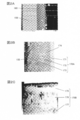
- 2A is an SEM (scanning electron microscope) image showing a typical configuration of an oxide film that is an example of a surface treatment formed on the surface of the main shaft of the refrigerant compressor shown in FIG. 1A
- FIG. FIG. 2C is a TEM (transmission electron microscope) image showing another configuration of the oxide film
- FIG. 2C is a TEM (transmission electron microscope) image showing another configuration of the coating film.
- FIG. 3A is a TEM (transmission electron microscope) image showing a typical configuration of an oxide film that is an example of a surface treatment formed on the surface of the main shaft of the refrigerant compressor shown in FIG. 1A
- FIG. It is a SIM (scanning ion microscope) image which shows the other structure of a film.
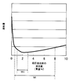
- FIG. 4 is a graph showing the relationship between the amount of extreme pressure additive added to the lubricating oil used in the refrigerant compressor shown in FIG. 1A and the amount of wear of the main shaft and main bearing of the refrigerant compressor.
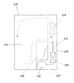
- FIG. 5 is a schematic diagram illustrating an example of a configuration of a refrigeration / refrigeration apparatus including the refrigerant compressor illustrated in FIG. 1A.
- Refrigerant compressor in a sealed container, with a kinematic viscosity at 40 ° C. for reserving lubricating oil of 0.1mm 2 /S ⁇ 5.1mm 2 / S, driven by an electric element and the electromotive element
- a compression element that compresses the refrigerant, and the compression element includes a crankshaft including a main shaft and an eccentric shaft as a shaft portion, a main bearing that supports the main shaft as a bearing portion that supports the shaft portion, and the And an eccentric bearing that supports the eccentric shaft, and at least one surface of the main shaft and the eccentric shaft is subjected to a surface treatment having a hardness equal to or higher than that of the bearing portion.
- the surface of the main shaft or the surface of the eccentric shaft, or both the surface of the main shaft and the surface of the eccentric shaft are subjected to high hardness surface treatment. Therefore, even if the lubricating oil has a low viscosity, the shaft portion and the bearing portion can be favorably lubricated. Thereby, since the abrasion of the sliding surface of the shaft portion can be satisfactorily suppressed, the reliability of the refrigerant compressor can be further improved.
- the base material of the shaft portion may be an iron-based material
- the surface treatment may be an oxide film
- the surface treatment is an iron-based oxide film
- the surface of the shaft portion main shaft and / or eccentric shaft
- the surface treatment is an iron-based oxide film
- the oxide film includes at least one of a portion containing diiron trioxide (Fe 2 O 3 ) on the outermost surface and a portion composed of at least microcrystals. It may be configured.
- the outermost surface of the oxide film has a high hardness. Therefore, since the wear of the sliding surface of the shaft portion (main shaft and / or eccentric shaft) can be satisfactorily suppressed, the reliability of the refrigerant compressor can be further improved.
- the ratio L / D between the length L of the bearing portion and the inner diameter D of the bearing portion may be in the range of 0.10 to 1.20.
- the lubricating oil has a low viscosity and the L / D of the bearing portion (main bearing and / or eccentric bearing) is within the above range, the wear of the sliding surface of the shaft portion is well suppressed. Can do. Therefore, the reliability of the refrigerant compressor can be further improved.
- the lubricating oil may be at least one selected from the group consisting of mineral oil, alkylbenzene oil, and ester oil, and the lubricating oil may be the mineral oil.
- the alkylbenzene oil may be used, and an extreme pressure additive may be contained in an amount of 0.5 to 8.0% by weight.
- the lubricating oil may be the ester oil and contain 2.0 to 4.0% by weight of an extreme pressure additive.
- the extreme pressure additive may be a phosphorus compound.
- the lubricating oil may include an oily agent.
- the electric element may be configured to be inverter-driven at a plurality of operating frequencies.
- the present disclosure includes a refrigeration / refrigeration apparatus having a refrigerant circuit including the refrigerant compressor, the radiator, the pressure reducing device, and the heat absorber configured as described above, and having a refrigerant circuit in which these are connected in a ring shape by piping. .
- FIG. 1A is a cross-sectional view of the refrigerant compressor 100 according to Embodiment 1 of the present disclosure.
- the refrigerant compressor 100 fills the sealed container 101 with, for example, R600a as refrigerant gas, and stores mineral oil as the lubricating oil 103 at the bottom.
- Lubricating oil 103 in the present disclosure, the kinematic viscosity at viscosity of low viscosity in the range of VG0 ⁇ VG5 (40 °C falls within the range of 0.1mm 2 /S ⁇ 5.1mm 2 / S Grade).
- the lubricating oil 103 is a low-viscosity mineral oil, but the lubricating oil 103 is not limited to this as described later. Further, the lubricating oil 103 may contain an extreme pressure additive or an oily agent, as will be described later.
- an electric element 106 and a compression element 107 are accommodated.
- the electric element 106 includes a stator 104 and a rotor 105.
- the compression element 107 has a reciprocating configuration driven by the electric element 106, and includes a crankshaft 108, a cylinder block 112, a piston 120, and the like.
- the crankshaft 108 includes a main shaft 109 in which the rotor 105 is press-fitted and fixed, and an eccentric shaft 110 formed eccentrically with respect to the main shaft 109.
- An oil supply pump (not shown) is provided at the lower end of the crankshaft 108.
- the cylinder block 112 is made of cast iron, for example, and forms a substantially cylindrical bore 113 and includes a main bearing 114 that supports the main shaft 109 of the crankshaft 108.
- a piston 120 is inserted so as to be able to reciprocate, whereby a compression chamber 121 is formed.
- the piston pin 115 has a substantially cylindrical shape, for example, and is disposed in parallel with the eccentric shaft 110. The piston pin 115 is locked to a piston pin hole formed in the piston 120 so as not to rotate.
- the connecting means 117 is made of, for example, an aluminum casting product, and includes an eccentric bearing 119 that supports the eccentric shaft 110, and connects the eccentric shaft 110 and the piston 120 via the piston pin 115.
- the end surface of the bore 113 is sealed with a valve plate 122.
- the main shaft 109 and the eccentric shaft 110 included in the crankshaft 108 are collectively referred to as “shaft portions”. Further, the main bearing 114 of the cylinder block 112 that supports the main shaft 109 and the eccentric bearing 119 of the connecting means 117 that supports the eccentric shaft 110 are collectively referred to as a “bearing portion”.
- the cylinder head 123 forms a high pressure chamber (not shown), and is fixed to the opposite side of the bore 113 in the valve plate 122.
- a suction tube (not shown) is fixed to the sealed container 101 and connected to the low-pressure side (not shown) of the refrigeration cycle, and guides the refrigerant gas into the sealed container 101.
- the suction muffler 124 is sandwiched between the valve plate 122 and the cylinder head 123.
- the rotor 105 of the electric element 106 is rotated.
- the rotor 105 rotates the crankshaft 108, and the eccentric motion of the eccentric shaft 110 drives the piston 120 from the coupling means 117 via the piston pin 115.
- the piston 120 reciprocates in the bore 113, sucks the refrigerant gas introduced into the sealed container 101 through the suction tube from the suction muffler 124, and compresses it in the compression chamber 121.
- the specific drive method of the refrigerant compressor 100 is not specifically limited.
- the refrigerant compressor 100 may be driven by simple on / off control, but may be inverter-driven at a plurality of operating frequencies.
- the inverter drive in order to optimize the operation control of the refrigerant compressor 100, a low speed operation in which the amount of oil supplied to each sliding portion is reduced or a high speed operation in which the rotational speed of the electric element 106 is increased occurs. To do.
- the refrigerant compressor 100 since the wear of the main shaft 109 can be satisfactorily suppressed as described later, the reliability of the refrigerant compressor 100 can be improved.
- the main shaft 109 of the crankshaft 108 is rotatably fitted to the main bearing 114 to constitute a sliding portion. Therefore, for the sake of convenience of explanation, a sliding portion constituted by the main shaft 109 and the main bearing 114 is referred to as a “main shaft sliding portion”.
- the eccentric shaft 110 of the crankshaft 108 is rotatably fitted to the eccentric bearing 119 to form a sliding portion. Therefore, for the sake of convenience of explanation, the sliding portion constituted by the eccentric shaft 110 and the eccentric bearing 119 is referred to as an “eccentric shaft sliding portion”.
- the “spindle sliding portion” and the “eccentric shaft sliding portion” are collectively referred to as “shaft portion sliding portion”.
- the lubricating oil 103 is supplied from the oil supply pump to each sliding portion. Thereby, each sliding part is lubricated.
- the lubricating oil 103 controls the seal between the piston 120 and the bore 113.
- FIG. 1B is an enlarged view of the main shaft 109 and the main bearing 114 surrounded by a broken-line circle in the refrigerant compressor 100 shown in FIG. 1A, and illustrates the length L of the main bearing 114 and the inner diameter D of the main bearing 114. . That is, in FIG. 1B, the main shaft sliding portion is shown enlarged among the shaft portion sliding portions.
- the main shaft 109 and the main bearing 114 are in metal contact.
- the refrigerant compressor 100 is started, a rotational motion starts from the metal contact state, so that a large frictional resistance is applied to the spindle sliding portion. Therefore, in the first embodiment, the surface of the main shaft 109 is subjected to a surface treatment having a hardness equal to or higher than that of the main bearing 114.
- the surface of the eccentric shaft 110 is subjected to a surface treatment having a hardness equal to or higher than that of the eccentric bearing 119.
- the surface treatment of the shaft portion is performed on both surfaces of the main shaft 109 and the eccentric shaft 110.
- the surface treatment may be performed only on the surface of the main shaft 109 or the surface of the eccentric shaft 110. It may be applied only to the surface.
- the surface treatment applied to the surface of the shaft portion has a hardness at least equivalent to, or equivalent to or higher than that of the bearing portion (main bearing 114 and / or eccentric bearing 119). If it is, it will not specifically limit, However, In this Embodiment 1, the oxide film mentioned later can be mentioned as a preferable example, for example. As a result, not only can abnormal wear due to metal contact during startup be prevented, but the shaft portion and the bearing portion can be well lubricated even if the lubricating oil 103 has a low viscosity within the range of VG0 to VG5. As a result, the wear of the shaft sliding portion can be satisfactorily suppressed. As a result, the reliability of the refrigerant compressor 100 can be further improved.
- the crankshaft 108 including the main shaft 109 and the eccentric shaft 110 uses gray cast iron (FC cast iron) as a base material, and a surface treatment (an oxide film or the like described later) is formed on the surface thereof.
- the base material of the crankshaft 108 is not limited to gray cast iron, and may be any known iron-based material. Typical examples of the base material include, but are not limited to, cast iron including gray cast iron.
- the base material may be a steel material or a sintered material. An iron-based material may be used.
- the specific type of cast iron is not particularly limited, and may be gray cast iron (ordinary cast iron, FC cast iron), spheroidal graphite cast iron (FCD cast iron), or other cast iron as described above. It may be.
- the ratio L / D between the length L of the main bearing 114 and the inner diameter D of the main bearing 114 is 0.10 to 1.20. It is preferable to be within the range.
- the oil 103 having a lower viscosity is used as the lubricating oil 103, if the L / D is reduced, the lubricating effect by the lubricating oil 103 may not be sufficiently obtained.
- the shaft sliding portion of the refrigerant compressor 100 uses a surface treatment having a hardness equal to or higher than that of the bearing portion, such as an oxide film described later. Even when / D is within the above range and the lubricating oil 103 has a low viscosity, a good lubricating effect can be realized. Therefore, the reliability of the shaft portion sliding portion can be further improved.
- the upper limit of L / D should just be 1.20 or less, the upper limit of L / D can be 0.45 or less. Therefore, a more preferable range of L / D can be in the range of 0.10 to 0.45.
- a nano-indentation device manufactured by Sienta Omicron Co., Ltd. is used to measure the shaft surface treatment (such as an oxide film to be described later) or the bearing surface hardness (measurement hardness). be able to.
- the indenter is pushed in and maintained for a certain period of time, then unloaded a little and then pushed in with a higher load than before, 15 times, a load-unload test up to a maximum of 1N repeat. As a result, the hardness of the measurement target and the hardness in the depth direction of the measurement target can be measured.
- the surface treatment of the shaft portion (at least one of the main shaft 109 of the crankshaft 108 and the eccentric shaft 110) is performed on the bearing portion (main bearing 114) that is the counterpart sliding member. And at least one of the eccentric bearings 119).
- the hardness in the present disclosure is one of the mechanical properties of a substance or material, particularly at or near the surface, and it is difficult for the object to deform when the material is about to be deformed or scratched by a foreign object. Now, it can be defined as the difficulty of scratching an object.
- measurement means definitions
- corresponding values hardness scales
- sliding members are metal or non-ferrous metal, sliding using the same indentation hardness test method (for example, nanoindentation method, Vickers hardness method, Rockwell hardness method, etc.) What is necessary is just to judge whether the film of the surface of a member is harder than an other party sliding member.
- indentation hardness test method for example, nanoindentation method, Vickers hardness method, Rockwell hardness method, etc.
- the determination can be made by a ring-on-disk wear test.
- the evaluation method there is a method in which a film is formed on the disk surface, the load is 1000 N, the rotational speed is 1 m / s, and it is operated for about one hour in a state immersed in oil to observe the state of the sliding surface. Can do. As a result, it may be determined that the harder one of the disks provided with the ring and the coating is relatively hard.
- FIG. 2A is an SEM (scanning electron microscope) image showing a configuration example of a typical oxide film 160
- FIG. 2B is a TEM (transmission electron microscope) image showing the structure of another typical oxide film 170A
- FIG. 2C is a TEM (transmission electron microscope) image showing the structure of another representative oxide film 170B
- 3A is a TEM (transmission electron microscope) image showing a typical configuration of another typical oxide film 180A
- FIG. 3B shows another configuration of another typical oxide film 180B. It is a SIM (scanning ion microscope) image.
- an oxide film which is a representative example of the surface treatment with high hardness applied to the surface of the shaft portion, is formed by oxidizing the surface of the iron-based material as a base material.
- the oxide film having such a preferable structure include oxide films 160, 170A, 170B, 180A, and 180B shown in FIGS. 2A to 3B, respectively.
- the oxide film 160 shown in FIG. 2A includes a portion containing diiron trioxide (Fe 2 O 3 ) on the outermost surface side, and the base 150 on the base 150 side.
- the silicon-containing portion contains more silicon (Si) than the material 150.
- the oxide film 160 may include a spot-like silicon-containing portion that is located on the surface side of the silicon-containing portion and has a silicon (Si) content that is partially higher than its surroundings. Further, in this oxide film 160, in order from the outermost surface, the most occupied component is ferric trioxide (Fe 2 O 3 ) and the most occupied component is triiron tetroxide (Fe 3 O 4 ). And at least a portion.
- the most occupied component is ferric trioxide (Fe 2 O 3 ) and the most occupied component is triiron tetroxide (Fe 3 O 4 ).
- the oxide film 160 will be specifically described with reference to FIG. 2A.
- this oxide film 160 is formed on base material 150 made of spheroidal graphite cast iron (FCD cast iron) (on the right side of base material 150 in FIG. 2A).
- FCD cast iron spheroidal graphite cast iron
- the intensity ratio of iron (Fe) is smaller in the oxide film 160 than in the base material 150. Further, it tends to slightly increase inside the oxide film 160. Further, the intensity ratio of oxygen (O) is significantly higher in the oxide film 160 than the base material 150. Furthermore, the strength ratio of silicon (Si) is higher on the base material 150 side of the oxide film 160 than on the base material 150. In addition, in the oxide film 160, the intensity ratio of silicon (Si) decreases at a stretch, and almost falls below the detection limit on the outermost surface side.
- the oxide film 160 has ferric trioxide (Fe 2 O 3 ) and / or triiron tetroxide (Fe It is considered that a crystal structure that contributes to wear resistance, such as 3 O 4 ), was generated.
- the most occupied component is ferric trioxide (Fe 2 O 3 ) (for convenience, ferric trioxide (Fe 2 O 3 ), that is, “III part” based on the name of “iron (III) oxide”) and a part where the most occupying component is triiron tetroxide (Fe 3 O 4 ) iron (Fe 3 O 4) or "iron (III) oxide of iron (II)" based on the names of called “II, III portion".) and in need only be at least configured (coating structure 1).
- the oxide film 160 shown in FIG. 2A in order from the outermost surface (sliding surface), the most and III part number occupies component is diiron trioxide (Fe 2 O 3), most occupied component triiron tetraoxide
- the II and III parts which are iron (Fe 3 O 4 ) and the part where the most occupied component is iron oxide (FeO) (for convenience, based on the name of iron oxide (FeO), that is, “iron (II) oxide” (Referred to as “II portion”).
- Both the coating composition 1 and the coating composition 2 in the oxide coating 160 are mainly composed of diiron trioxide (Fe 2 O 3 ) in the outermost portion III, and below that is triiron tetroxide (Fe 3).
- the II and III parts having O 4 ) as the main component are located. Since ferric tetroxide (Fe 3 O 4 ) is a stronger cubic crystal in terms of crystal structure than ferric trioxide (Fe 2 O 3 ), the III part is supported by the underlying II and III parts. Become.
- the II portion containing iron oxide (FeO) as a main component is located below the II and III portions. Since iron oxide (FeO) exists in an amorphous state having no crystal structure at the surface interface of the substrate 150, the presence of weak structures such as crystal grain boundaries or lattice defects can be sufficiently suppressed. Therefore, when the sliding member slides, the proof stress of the oxide film 160 against the load is improved. As a result, there is a possibility that it contributes to suppression of peeling of the oxide film 160 and improvement of adhesion of the oxide film 160 to the substrate 150.
- the II and III portions can be classified into a portion having a small content on the surface side and a portion having a small content on the base material 150 side based on the content of silicon (Si).
- the upper part having a low silicon (Si) content is referred to as “II, III part a” for convenience, and the lower part having a high silicon (Si) content is referred to as “II, III part b” for convenience.
- the interface between the II, III portion a and the II, III portion b coincides with the location where the intensity ratio of silicon (Si) immediately starts to decrease within the oxide film 160 in the EDS analysis described above.
- a portion (II, III portion, or II, III portion and II portion) located on the base material 150 side in the oxide film 160 contains silicon containing more silicon (Si) than the base material 150. Contains part. Further, in the oxide film 160, a portion (at least one of the II, III portion and the III portion) which is on the surface side of the silicon-containing portion is partially not silicon (not shown) as compared with the surrounding composition. It contains spot-like silicon-containing portions with a high Si) content. This spot-like silicon-containing portion is also observed as a white spot in, for example, TEM (transmission electron microscope) observation, and can be referred to as a “white portion”. In this “white part”, an increase in the concentration or strength of silicon (Si) is observed.
- the upper II, III part a of the II, III part has a lower silicon (Si) content than the lower II, III part b (silicon-containing part),
- the oxide film 160 illustrated in FIG. 2A that includes a “white portion”, that is, a spot-like silicon-containing portion
- the III portion on the outermost surface side hardly contains silicon (Si).
- a “white part”, that is, a spot-like silicon-containing part can also be present in the III part.
- silicon (Si) compounds having different structures such as silicon dioxide (SiO 2 ) and / or firelite (Fe 2 SiO 4 ) are present.
- silicon (Si) compounds having different structures such as silicon dioxide (SiO 2 ) and / or firelite (Fe 2 SiO 4 ) are present.
- silicon (Si) compound in the “white part”, not silicon (Si) compound but silicon (Si) may exist in a dissolved state (silicon (Si) exists alone). Therefore, in the III part and / or II, III part a, not only a part containing a silicon (Si) compound exists but also a silicon (Si) solid solution part as a spot-like silicon-containing part. There is a case.
- the oxide film 160 may have at least a layered silicon-containing portion (part of II, III portion, II portion, etc.) on the base material 150 side, and preferably is more than the silicon-containing portion. What is necessary is just to have the spot-like silicon-containing part with more silicon (Si) content than the circumference
- the coating configuration 1 including the III portion and the II, III portion, or the coating configuration 2 including the III portion, the II, III portion, and the II portion can be given.
- the structure of the oxide film 160 is not limited to these.
- the oxide film 160 may include a structure in which the III portion, II, III portion a, and II, III portion b (and II portion) are stacked in this order from the outermost surface.
- the oxide film 160 is not limited to these three-layer or four-layer configurations. Other layers other than these may be included, a configuration in which some layers are not included, or a configuration in which some layers are replaced may be employed.
- a configuration including other layers, a configuration not including some layers, or a configuration in which the stacking order of each layer is different can be easily realized by adjusting various conditions described later. Can do.
- oxide film 170A shown in FIG. 2B or the oxide film 170B shown in FIG. 2C will be described.
- These oxide films 170A and 170B have a composition A portion in which the most occupying component is ferric trioxide (Fe 2 O 3 ). And the most occupying component is triiron tetroxide (Fe 3 O 4 ), and the composition B portion containing a silicon (Si) compound, and the most occupying component is triiron tetroxide (Fe 3 O 4 ). And a composition C portion having a silicon content higher than that of the composition B portion.
- these oxide films 170A and 170B are further arranged in order from the outermost surface, outermost portions 171 and 175 that are composition A portions, intermediate portions 172 and 176 that are composition B portions, and You may comprise at least from the inner parts 173 and 177 which are the composition C parts.
- the silicon (Si) compound may be included in the composition A portion, and the silicon (Si) compound is not particularly limited, but silicon dioxide (SiO 2 ) or fire. At least one of light (Fe 2 SiO 4 ) can be mentioned.
- the oxide film 170A shown in FIG. 2B will be specifically described.
- the oxide film 170A is formed on a base material 150 made of, for example, gray cast iron (FC cast iron) (on the right side of the base material 150 in FIG. 2B).
- the oxide film 170A has a three-part structure (three layers) of the outermost portion 171 (first layer), the intermediate portion 172 (second layer), and the inner portion 173 (third layer) from the outermost surface. The structure is clearly confirmed. Also, it is confirmed that the white portion 174 is partially present in the intermediate portion 172 that is the second layer.
- this oxide film 170A was subjected to EDS analysis in the same manner as the oxide film 160 described above, a specific result is not shown, but iron (Fe) is covered from the outermost part 171 to the inner part 173 of the oxide film 170A. ) And oxygen (O).
- silicon (Si) is hardly present or present in the outermost portion 171 in a small amount. Further, silicon (Si) is present in a part of the intermediate part 172 and most parts of the inner part 173.
- oxygen (O) that does not bind to iron (Fe) and bonds to silicon (Si) exists, and either iron (Fe) or silicon (Si) exists.
- Oxygen (O) is also present. Therefore, in the white portion 174, a plurality of types of silicon (Si) compounds having different structures such as silicon dioxide (SiO 2 ) and firelite (Fe 2 SiO 4 ) are present.
- the oxide film 170B shown in FIG. 2C will be specifically described. As shown in FIG. 2C, the oxide film 170B is formed on the base material 150 (not shown), and, like the oxide film 170A, from the outermost surface, the outermost portion 175 (first layer) and the intermediate portion 176 ( It is clearly confirmed that it has a three-part structure (three-layer structure) of the second layer) and the inner part 177 (third layer).
- the outermost part 175 is a composition A part like the outermost part 171 of the oxide film 170A, and the most occupied component is a part of ferric trioxide (Fe 2 O 3 ).
- the intermediate portion 176 is a portion of the composition B like the intermediate portion 172 of the oxide film 170A, and the most occupied component is triiron tetroxide (Fe 3 O 4 ) and contains a silicon (Si) compound. is there.
- the most occupying component is triiron tetroxide (Fe 3 O 4 ), and the content of silicon is larger than that in the composition B portion. Part.
- the concentration of silicon (Si) is high in the substrate 150, and the substrate 150 side of the oxide film 170B is high. Even in an inner portion 177, the concentration of silicon (Si) is high. On the other hand, at the interface between the inner portion 177 and the intermediate portion 176, the concentration of silicon (Si) decreases at a stretch.
- the intermediate portion 176 has a white portion 174 as in the intermediate portion 172 of the oxide film 170A.
- a part corresponding to the white portion 174 an increase in the concentration of silicon (Si) is observed in the EDS analysis.
- silicon (Si) was hardly confirmed in the outermost part 171 of the oxide film 170A, the presence of the white part 174 was confirmed in the outermost part 175 of the oxide film 170B, which corresponds to the white part 174. In some places, the concentration of silicon (Si) is increased.
- Si silicon
- EESL electron beam energy loss spectroscopy
- the oxide film 170B shown in FIG. 2C has basically the same structure as the oxide film 170A shown in FIG. 2B, but not only the inner portion 177 and the intermediate portion 176 but also the outermost portion 175. The difference is that a silicon (Si) compound such as silicon (SiO2) is present.
- the oxide film 170A shown in FIG. 2B or the oxide film 170B shown in FIG. 2C is, in order from the outermost surface, the outermost portion 171 or the outermost portion 175 that is the composition A portion, and the middle that is the composition B portion. It is comprised at least from the part 172 or the intermediate part 176, and the inner part 173 or the inner part 177 which is a composition C part.
- the structure of these oxide films 170A and 170B is not limited to this three-layer structure.
- the oxide films 170A and 170B may be configured to include the above-described composition A portion, composition B portion, and composition C portion, it is needless to say that portions other than these may be included. Further, the oxide films 170A and 170B are not limited to the configuration in which the composition A portion, the composition B portion, and the composition C portion are laminated in this order from the outermost surface. For example, another configuration of the oxide films 170A and 170B includes a configuration in which the composition B portion, the composition A portion, and the composition C portion are laminated in this order from the outermost surface. As described above, a configuration including other portions or a configuration in which the stacking order of each portion is different can be easily realized by adjusting various conditions described later.
- oxide film 180A shown in FIG. 3A or the oxide film 180B shown in FIG. 3B will be described.
- These oxide films 180A and 180B include a first portion 181 made of at least microcrystals and a second structure containing a columnar structure. It is the structure containing the part 182 and / or the 3rd part 183 containing a layered structure
- a first portion 181 located on the outermost surface, a second portion 182 located below the first portion 181 and further below the second portion 182 are provided. And at least the third portion 183 located in the region.
- the crystal grain size of the first part 181 may be smaller than that of the second part 182.
- the crystal grain size of the microcrystals constituting the first portion 181 is not particularly limited, but can be in the range of 0.001 to 1 ⁇ m.
- the first portion 181 is substantially composed of a single portion, but the configuration of the first portion 181 is not limited to this.
- the first portion 181 may be composed of at least a first a portion 181a and a first b portion 181b having different crystal densities.
- the specific configurations of the first a portion 181a and the first b portion 181b are not particularly limited, but the first a portion 181a is located on the surface side, and the first b portion 181b is the first a portion
- the crystal density of the first a portion 181a may be lower than the crystal density of the first b portion 181b.
- the specific configuration of the first portion 181 to the third portion 183 is not particularly limited, but when the first portion 181 includes the first a portion 181a, the first a portion 181a has an aspect ratio.
- You may contain the elongate acicular structure
- the second portion 182 may contain a vertically long crystal structure having an aspect ratio in the range of 1 to 20.
- the third portion 183 may contain a horizontally long crystal structure having an aspect ratio in the range of 0.01 to 1.
- the oxide film 180A shown in FIG. 3A will be specifically described.
- the oxide film 180A includes a first portion 181 made of microcrystals from the outermost surface, a second portion 182 containing a vertically long columnar structure below it, and a horizontally elongated layered structure below the first portion 181. Is formed at least from the third portion 183 containing the base material 150 and below the third portion 183.
- the third portion 183 is located below the second portion 182.
- the third portion 183 is composed of a structure having a vertical diameter of several tens of nm or less and a horizontal diameter of several hundred nm.
- the aspect ratio obtained by dividing the vertical diameter of the structure by the horizontal diameter is in the range of 0.01 to 0.1, and therefore the structure is long in the horizontal direction. Therefore, it can be seen that the third portion 183 has a “laterally long” layered structure with a small aspect ratio.
- the third portion 183 cementite which is the structure of the base material 150 is confirmed.
- cementite is not confirmed in the first portion 181 and the second portion 182. Therefore, it is estimated that the third portion 183 is formed by oxygen being diffused into the base material 150 by the oxidation treatment of the base material 150.
- the first portion 181 and the second portion 182 are presumed to be formed by the growth of oxide on the surface of the substrate 150.
- the oxide film 180A (or the oxide film 180B shown in FIG. 3B) may be configured to include the first portion 181 and at least one of the second portion 182 and the third portion 183. That is, the oxide films 180A and 180B are configured to include two layers of the first portion 181 and the second portion 182 by adjusting various conditions described later, or the first portion 181 and the third portion. A structure including two layers of 183 can be obtained. Further, by adjusting various conditions described later, oxide film 180A (or oxide film 180B) includes three layers of first portion 181, second portion 182 and third portion 183 as described above. It becomes composition.
- a three-layer structure including a first portion 181, a second portion 182 and a third portion 183 in order from the outermost surface is exemplified.
- portions other than these may be included, and the stacking order of these portions can be appropriately set by adjusting various conditions.
- the first portion 181 is composed of a structure made of microcrystals, but this does not mean that the first portion 181 does not contain any structure other than microcrystals.
- the first portion 181 is substantially composed of microcrystals, and may include other structures or the like within the range of “impurities”. Therefore, the first portion 181 may be configured to include at least a microcrystal, in other words, a configuration including the microcrystal as a main structure, and may include other structures.
- the second portion 182 only needs to contain a columnar structure, may contain another structure, and may be substantially composed of a columnar structure.
- the 3rd part 183 should just contain the layered structure
- the first portion 181, the second portion 182 and the third portion 183 are configured as an oxide film 180A (or oxide film 180B) on the surface of the base material 150, so that they are equal to or more than the bearing portion. Needless to say, these portions may include a tissue other than the essential tissue.
- the first portion 181 may have a structure in which nano-level microcrystals are spread, and the upper limit of the crystallite grain size is not limited to 100 nm or less.
- the grain size of the microcrystals may be in the range of 0.001 ⁇ m (1 nm) to 1 ⁇ m (1000 nm).
- the second portion 182 only needs to have a structure in which an infinite number of “longitudinal” columnar structures having a large aspect ratio are formed in the same direction. It is not limited within the range of 10.
- the aspect ratio of the columnar structure may be in the range of 1-20.
- the third portion 183 may have a configuration in which a “laterally long” layered structure having a small aspect ratio is formed, and the aspect ratio of the layered structure is 0.01 to 0.00. It is not limited within the range of 1.
- the aspect ratio of the layered structure may be in the range of 0.01 to 1.
- the grain size of the microcrystals of the first part 181, the aspect ratio of the columnar structure of the second part 182, and the aspect ratio of the layered structure of the third part 183 can be determined by appropriately setting various conditions described later. , Can be set within a suitable range.
- the oxide film 180B shown in FIG. 3B will be specifically described.
- the oxide film 180B includes a first portion 181 made of microcrystals from the outermost surface, a second portion 182 containing a vertically long columnar structure below it, and a horizontally elongated layered structure below the first portion 181. Is formed at least from the third portion 183 containing the base material 150 and below the third portion 183.
- the first portion 181 can be divided into a first a portion 181a and a first b portion 181b having different crystal densities.
- the first portion 181 formed on the outermost surface has a structure in which microcrystals having a particle diameter of 100 nm or less are spread like the first portion 181 of the oxide film 180A.
- the first portion 181 in the oxide film 180B can be regarded as a “single layer” in the same manner as the first portion 181 in the oxide film 180A in that the first portion 181 is substantially composed of microcrystals.
- the density of microcrystals is used as a reference, it can be divided into a first-a portion 181a on the outermost surface side and a first-b portion 181b on the base material 150 (second portion 182) side.
- the first a portion 181a has a lower crystal density (low density) than the first b portion 181b below.
- the first-a portion 181a is made of at least a microcrystal and has void portions (portions that appear dark in FIG. 3B). Further, the first a portion 181a contains a vertically long acicular structure having a length on the short axis side of 100 nm or less and an aspect ratio in the range of 1 to 10. On the other hand, the first b portion 181b below the first a portion 181a does not contain much voids or needle-like structures. The first b portion 181b has a structure in which nano-level microcrystals are spread.
- the second portion 182 is located below the first b portion 181b.
- the second portion 182 is composed of a structure having a vertical diameter of about 500 nm to 1 ⁇ m and a horizontal diameter of about 100 nm to 150 nm. Since the aspect ratio obtained by dividing the vertical diameter of the tissue by the horizontal diameter is in the range of about 3 to 10, the structure is long in the vertical direction. Therefore, the second portion 182 has innumerable “longitudinal” columnar structures having a large aspect ratio formed in the same direction.
- a third portion 183 is located below the second portion 182.
- the third portion 183 is composed of a structure having a vertical diameter of several tens of nm or less and a horizontal diameter of several hundred nm.
- the aspect ratio obtained by dividing the vertical diameter of the structure by the horizontal diameter is in the range of 0.01 to 0.1, and therefore the structure is long in the horizontal direction. Therefore, the third portion 183 has a “laterally long” layered structure with a small aspect ratio.
- the first portion 181 (the first a portion 181a and the first b portion 181b) may be a structure in which nano-level microcrystals are spread, and the grain size of the microcrystals Is not limited to 100 nm or less. Similar to the first portion 181 in the oxide film 180A, the grain size of the microcrystals may be in the range of, for example, 0.001 ⁇ m (1 nm) to 1 ⁇ m (1000 nm).
- the ratio of the void portion is 10% or more.
- the proportion of the voids is preferably less than 10%. If the proportion of the void portion is too large, the denseness (mechanical strength) of the structure is not sufficiently improved and the first a portion 181a is well supported, although depending on the comparison with the first a portion 181a. There is a risk that it will not be possible.
- the volume occupancy rate of the void portion (for example, 10%) can be used.
- the first a portion 181a contains not only microcrystals but also longitudinal needle-like structures, but the aspect ratio of the needle-like structures is not particularly limited.
- the needle-like structure has a length on the minor axis side of 100 nm or less and an aspect ratio in the range of 1 to 10, but the aspect ratio may be in the range of 1 to 1000.
- the film thickness of any of these oxide films 160 to 180B is not particularly limited, but can be in the range of 1 to 5 ⁇ m, for example.
- a known iron-based material can be suitably used as the substrate 150.
- the iron-based material that is the substrate 150 is used.
- the material may contain silicon in the range of 0.5 to 10%.
- the oxide films 160 to 180B used as the surface treatment in the present disclosure are the above-described configuration example 1 (oxide film 160), configuration example 2 (oxide films 170A and 170B), or configuration example 3 (oxide films 180A and 180B).
- the present invention is not limited thereto, and may be an oxide film having another configuration.
- various conditions such as the specific configuration of each part or layer, the stacking order, the thickness, and the like can be adjusted appropriately as described above. It is feasible.
- such various conditions are not particularly limited, but representatively, a manufacturing method (forming method) of the oxide films 160 to 180B can be mentioned.
- the manufacturing method of the oxide coatings 160 to 180B is not particularly limited, and a known iron-based material oxidation method can be suitably used.
- the manufacturing conditions and the like can be appropriately set according to various conditions such as the type of the iron-based material that is the substrate 150, its surface condition (such as the above-described polishing finish), and the physical properties of the desired oxide film 160 to 180B.
- a gray cast iron that is the base material 150 within a range of several hundred degrees Celsius, for example, within a range of 400 to 800 degrees Celsius, using a known oxidizing gas such as carbon dioxide (carbon dioxide gas) and a known oxidation facility.
- the specific material of the base material 150 (the cast iron, steel material, sintered material, etc. described above), the components contained in the base material 150 (for example, the content of silicon (Si) in the case of cast iron) Or, in the case of other iron-based materials, the content of carbon (C) or an alloy component, etc.), and the surface state of the substrate 150 before forming the oxide film 160-180B (for example, prior surface treatment, etc.)
- the specific material of the base material 150 the cast iron, steel material, sintered material, etc. described above
- the components contained in the base material 150 for example, the content of silicon (Si) in the case of cast iron
- the content of carbon (C) or an alloy component, etc.) for example, prior surface treatment, etc.
- the surface state of the substrate 150 before forming the oxide film 160-180B for example, prior surface treatment, etc.
- FIG. 4 shows the amount of the extreme pressure additive that can be added to the lubricating oil 103 and the wear amount of the main shaft sliding portion (main shaft 109 and main bearing 114) among the shaft portion sliding portions of the refrigerant compressor 100. It is a graph which shows the relationship.
- the lubricating oil 103 has a low viscosity within the range of VG0 to VG5, and (2) the surface of the shaft portion.
- a surface treatment having a hardness equal to or higher than that of the bearing portion forming the above-described oxide films 160 to 180B as a preferred example
- wear of the sliding portion of the shaft portion is suppressed well, and refrigerant compression is performed.
- the reliability of the machine 100 can be further improved.
- the ratio between the length L of the bearing portion and the inner diameter D of the bearing portion is set.
- the lubricating oil composition used as the lubricating oil 103 By adjusting the composition (especially by adding an extreme pressure additive and / or an oily agent, which will be described later), the wear of the shaft sliding portion can be further suppressed, and the reliability of the refrigerant compressor 100 is improved. Can be made particularly good.
- the lubricating oil composition used as the lubricating oil 103 may contain as a main component an oily substance that satisfies the above-described constitution (1), that is, a low viscosity within the range of VG0 to VG5. At least one oily substance selected from the group consisting of benzene, alkylbenzene oil, and ester oil can be suitably used. These oily substances may be used alone or in combination of two or more.
- the combination of two or more kinds of oily substances here refers not only to a combination of two or more kinds of different oily substances corresponding to mineral oil, but also to one or more kinds of oily substances corresponding to mineral oil, for example, alkylbenzene oil This includes the case where one or more oily substances (or one or more oily substances corresponding to ester oil) are combined.
- the lubricating oil composition used as the lubricating oil 103 may be added with various additives to the above-mentioned one or more oily substances.
- Various additives known in the field of the lubricating oil 103 can be suitably used as such an additive, but typically, an extreme pressure additive, an oily agent, an antiwear agent, an antioxidant, an acid, Examples thereof include a scavenger, a metal deactivator, an antifoaming agent, a corrosion inhibitor, and a dispersant.
- an extreme pressure additive can be mentioned as a particularly preferable one in the present disclosure.
- An extreme pressure additive is added to a lubricating oil composition (one or more oily substances) for the purpose of reducing wear or suppressing seizure between the surfaces of a plurality of sliding members constituting a sliding portion, that is, sliding surfaces.
- a coating is formed on the sliding surface to realize wear reduction or suppression of seizure.
- extreme pressure additive known ones can be suitably used and are not particularly limited.
- phosphorus compounds such as phosphate esters, sulfur compounds such as sulfurized fatty acids or esters thereof, chlorine compounds, and the like.
- halogenated compounds such as hydrocarbons or fluorine-based hydrocarbons. Only one of these extreme pressure additives may be added to the lubricating oil composition, or two or more may be added in appropriate combination.
- phosphorus compounds can be preferably used.
- Typical phosphorus compounds include tricresyl phosphate (TCP), tributyl phosphate (TBP), and triphenyl phosphate (TPP).
- TCP can be used more preferably.
- the amount of the extreme pressure additive added to the lubricating oil composition is not particularly limited.
- the lubricating oil 103 is a low-polarity substance such as mineral oil or alkylbenzene oil
- a range of 0.5 to 8.0% by weight can be mentioned, and a range of 1 to 3% by weight can be mentioned as a more preferable range.
- the graph shown in FIG. 4 shows that when the oily substance of the lubricating oil composition is a low-polarity substance such as mineral oil, the added amount of the extreme pressure additive and the main shaft sliding part (shaft part) as described above. The relationship with the amount of wear of the sliding portion) is shown. The wear amount of the main shaft sliding portion (shaft portion sliding portion) is evaluated by a known Falex type friction tester.
- the wear amount can be significantly reduced within the range of 0.5 wt% or more and 8 wt% or less. If the addition amount is less than 0.5% by weight, the effect of reducing the wear amount cannot be said to be sufficient as shown in FIG. 4, and if the addition amount exceeds 8% by weight, the wear amount corresponding to the addition amount is reduced. In addition to not being able to obtain the effect, there is a tendency that the amount of wear slightly increases with an increase in the amount added.
- the graph shown in FIG. 4 is a curve having a minimum value of about 2% by weight added, so as shown in the range Mii in FIG. 4, 2% ⁇ 1% by weight, that is, 1% by weight. If it is in the range of 3% by weight or less, it is considered that a particularly good wear reduction effect can be obtained.
- the extreme pressure additive when the lubricating oil 103 (oily substance) is an ester oil, the extreme pressure additive can be added within a range of 2.0 to 4.0% by weight. Since ester oil is a polar oily substance, it is easily adsorbed by iron-based materials. Therefore, even if an extreme pressure additive is added to the lubricating oil composition containing lubricating oil (lubricating oil 103), the ester oil is adsorbed on the sliding surface prior to the extreme pressure additive. It becomes difficult for the extreme pressure additive to react with the sliding surface to form a film. Therefore, normally, the extreme pressure additive is not added to the lubricating oil 103 (lubricating oil composition) mainly composed of ester oil.
- the refrigerant compressor 100 includes at least the configurations (1) and (2).
- the oxide films 160 to 180B described above as the configuration (2) are preferably used. Used. Since such oxide films 160 to 180B are formed on the sliding surface of the shaft portion constituting the shaft portion sliding portion, the low-viscosity lubricating oil 103 satisfying the configuration of (1) is mainly composed of ester oil. Even with the lubricating oil composition, it is possible to satisfactorily exhibit effects such as wear reduction by the extreme pressure additive.
- the low-viscosity lubricant 103 is used, and the surface of the shaft portion constituting the shaft portion sliding portion is subjected to a high hardness surface treatment (such as the above-described oxide coatings 160 to 180B).
- a high hardness surface treatment such as the above-described oxide coatings 160 to 180B.
- the effect of the extreme pressure additive can be satisfactorily realized regardless of the type of the lubricating oil 103. Therefore, in the shaft sliding portion, the ratio L / D between the length L of the bearing portion and the inner diameter D of the bearing portion can be made smaller than the conventional one (configuration (3)). The reliability of 100 can be further improved.
- an oily agent may be added to the lubricating oil 103.
- the surface of the shaft sliding portion is subjected to a surface treatment with high hardness such as an oxide film 160 to 180B. Since a film can be formed on the sliding surface even by adding an oily agent, such a surface treatment can further improve the effect of reducing wear by the oily agent.
- the specific type of the oily agent is not particularly limited, and examples thereof include higher fatty acids, higher alcohols, esters, and metal soaps. These oil agents may be used alone or in combination of two or more. Further, the amount of the oily agent added is not particularly limited, but can be, for example, in the range of 0.01 to 1% by weight. In addition, it is preferable to add at least one extreme pressure additive to the lubricating oil 103 (lubricating oil composition), and it is possible to add at least one oily agent. You may add only an oil-based agent, without adding an agent. The same applies to other additives.
- FIG. 5 schematically shows a schematic configuration of a refrigeration / refrigeration apparatus including the refrigerant compressor 100 according to the first embodiment. Therefore, in this Embodiment 2, only the outline of the basic configuration of the freezing / refrigeration apparatus will be described.
- the freezing / refrigeration apparatus includes a main body 275, a partition wall 278, a refrigerant circuit 270, and the like.
- the main body 275 is configured by a heat insulating box, a door, and the like.
- the box has a structure in which one surface is opened, and the door is configured to open and close the opening of the box.
- the interior of the main body 275 is partitioned into a storage space 276 for goods and a machine room 277 by a partition wall 278.
- a blower (not shown) is provided in the storage space 276, a blower (not shown) is provided in the storage space 276, a blower (not shown) is provided.
- the inside of the main body 275 may be partitioned into a space other than the storage space 276 and the machine room 277.
- the refrigerant circuit 270 is configured to cool the interior of the storage space 276.
- the refrigerant circuit 270 includes the refrigerant compressor 100 described in the first embodiment, the radiator 272, the decompressor 273, and the heat absorber 274.
- the heat absorber 274 is disposed in the storage space 276.
- the cooling heat of the heat absorber 274 is agitated so as to circulate in the storage space 276 by a blower (not shown) as indicated by the broken arrow in FIG. Thereby, the inside of the storage space 276 is cooled.
- the refrigerant compressor 100 provided in the refrigerant circuit 270 includes (1) the lubricating oil 103 having a low viscosity within the range of VG0 to VG5, and (2) the shaft portion.
- the surface is subjected to a surface treatment having a hardness equal to or higher than that of the bearing portion (the above-described oxide films 160 to 180B are formed as a preferred example), and (3) the length L of the bearing portion
- the ratio L / D with the inner diameter D of the bearing portion can be made smaller than before, and (4) the effect of reducing wear due to the addition of the extreme pressure additive (and / or oily agent) is further improved. be able to. Thereby, the reliability of the refrigerant compressor 100 can be further improved.
- the refrigeration / refrigeration apparatus according to the second embodiment is equipped with the refrigerant compressor 100 according to the first embodiment.
- the sliding part provided in the refrigerant compressor 100 has excellent wear resistance and excellent adhesion to the sliding surface. Therefore, the refrigerant compressor 100 can reduce the sliding loss of the sliding portion, and can realize excellent reliability and excellent efficiency. As a result, since the refrigeration / refrigeration apparatus according to Embodiment 2 can reduce power consumption, energy saving can be realized and reliability can be improved.
- the present invention it is possible to provide a refrigerant compressor excellent in reliability while using a low-viscosity lubricating oil, and a refrigeration / refrigeration apparatus using the refrigerant compressor. Therefore, the present invention can be widely applied to various devices using a refrigeration cycle.
Landscapes
- Engineering & Computer Science (AREA)
- Chemical & Material Sciences (AREA)
- Mechanical Engineering (AREA)
- General Engineering & Computer Science (AREA)
- Oil, Petroleum & Natural Gas (AREA)
- Chemical Kinetics & Catalysis (AREA)
- General Chemical & Material Sciences (AREA)
- Organic Chemistry (AREA)
- Health & Medical Sciences (AREA)
- Emergency Medicine (AREA)
- Compressor (AREA)
Abstract
冷媒圧縮機(100)の密閉容器(101)内には、40℃での動粘度が0.1mm2 /S~5.1mm2 /Sの潤滑油(103)が貯留されるとともに、電動要素(106)および圧縮要素(107)が収容される。圧縮要素(107)は、軸部として、主軸(109)および偏心軸(110)を備えるクランクシャフト(108)と、軸受部として、主軸(109)を軸支する主軸受(114)および偏心軸(110)を軸支する偏心軸受(119)と、を備える。主軸(109)および偏心軸(110)の少なくとも一方の表面には、軸受部(主軸受(114)または偏心軸受(119))と同等以上の硬度を有する表面処理、例えば、酸化被膜が施されている。これにより、より粘度の低い潤滑油を用いても、摺動部において良好な信頼性を実現することができる。
Description
本発明は、冷蔵庫、エアーコンディショナー等に使用される冷媒圧縮機およびそれを用いた冷凍・冷蔵装置に関するものである。
近年、地球環境保護の観点から化石燃料の使用を少なくする高効率の冷媒圧縮機の開発が進められている。例えば、高効率化を図るために、冷媒圧縮機が備える摺動部材において、その摺動面に種々の被膜を形成するとともに、より低粘度の潤滑油を用いることが提案されている。
冷媒圧縮機は、摺動部材として、例えば、クランクシャフト、ピストン、連結手段のコンロッド等を備えており、クランクシャフトの主軸および主軸受、ピストンおよびボアー、ピストンピンおよびコンロッド、クランクシャフトの偏心軸およびコンロッド等は、いずれも互いに摺動部を形成している。
例えば、特許文献1では、金属材料からなる基材の表面にTi被膜を形成し、このTi被膜の上層に、さらに水素含有量が0原子%である非結晶硬質炭素被膜を形成した摺動部材が開示されている。この摺動部材を備える密閉型圧縮機においては、粘度グレードがVG10以下の低粘度の潤滑油を用いることができる。
あるいは、特許文献2では、摺動部材の基材の組織を改質した上で、その表面にリン酸塩被膜を形成した摺動部材が開示されている。この摺動部材を備える密閉型圧縮機においても、粘度グレートがVG10以下の低粘度の潤滑油を用いることができる。
最近では、潤滑油の粘度をさらに一層低粘度化することが検討されている。しかしながら、潤滑油の粘度グレードをVG10よりもさらに低くすると、摺動部の信頼性が低下するおそれがある。
本発明はこのような課題を解決するためになされたものであって、より粘度の低い潤滑油を用いても、摺動部において良好な信頼性を実現することが可能な冷媒圧縮機と、この冷媒圧縮機を備える冷凍・冷蔵装置とを提供することを目的とする。
本発明に係る冷媒圧縮機は、前記の課題を解決するために、密閉容器内に、40℃での動粘度が0.1mm2 /S~5.1mm2 /Sの潤滑油を貯留するとともに、電動要素および当該電動要素により駆動され冷媒を圧縮する圧縮要素を収容し、前記圧縮要素は、軸部として、主軸および偏心軸を備えるクランクシャフトと、前記軸部を軸支する軸受部として、主軸を軸支する主軸受および前記偏心軸を軸支する偏心軸受と、を備え、前記主軸および前記偏心軸の少なくとも一方の表面には、前記軸受部と同等以上の硬度を有する表面処理が施されている構成である。
前記構成によれば、主軸の表面または偏心軸の表面、もしくは、主軸の表面および偏心軸の表面の双方に高硬度の表面処理が施されている。そのため、潤滑油が低粘度のものであっても、軸部と軸受部とを良好に潤滑することができる。これにより、軸部の摺動面の摩耗を良好に抑制することができるので、冷媒圧縮機の信頼性をより一層良好なものとすることができる。
また、本発明に係る冷凍・冷蔵装置は、前記構成の冷媒圧縮機と、放熱器と、減圧装置と、吸熱器とを含み、これらを配管によって環状に連結した冷媒回路を備える構成である。
本発明の上記目的、他の目的、特徴、及び利点は、添付図面参照の下、以下の好適な実施態様の詳細な説明から明らかにされる。
本発明では、以上の構成により、より粘度の低い潤滑油を用いても、摺動部において良好な信頼性を実現することが可能な冷媒圧縮機と、この冷媒圧縮機を備える冷凍・冷蔵装置とを提供することができる、という効果を奏する。
本開示に係る冷媒圧縮機は、密閉容器内に、40℃での動粘度が0.1mm2 /S~5.1mm2 /Sの潤滑油を貯留するとともに、電動要素および当該電動要素により駆動され冷媒を圧縮する圧縮要素を収容し、前記圧縮要素は、軸部として、主軸および偏心軸を備えるクランクシャフトと、前記軸部を軸支する軸受部として、主軸を軸支する主軸受および前記偏心軸を軸支する偏心軸受と、を備え、前記主軸および前記偏心軸の少なくとも一方の表面には、前記軸受部と同等以上の硬度を有する表面処理が施されている構成である。
前記構成によれば、主軸の表面または偏心軸の表面、もしくは、主軸の表面および偏心軸の表面の双方に高硬度の表面処理が施されている。そのため、潤滑油が低粘度のものであっても、軸部と軸受部とを良好に潤滑することができる。これにより、軸部の摺動面の摩耗を良好に抑制することができるので、冷媒圧縮機の信頼性をより一層良好なものとすることができる。
前記構成の冷媒圧縮機においては、前記軸部の基材が鉄系材料であり、前記表面処理が酸化被膜である構成であってもよい。
前記構成によれば、表面処理が鉄系の酸化被膜であるため、軸部(主軸および/または偏心軸)の表面を高硬度にできるだけでなく、低粘度の潤滑油を保油できる等の効果も得られる。これにより、軸部の摺動面の摩耗を良好に抑制することができるので、冷媒圧縮機の信頼性をより一層良好なものとすることができる。
また、前記構成の冷媒圧縮機においては、前記酸化被膜は、最表面に三酸化二鉄(Fe2O3)を含有する部分、および、少なくとも微結晶で構成される部分の少なくともいずれかを含むことを構成であってもよい。
前記構成によれば、酸化被膜の最表面が高硬度なものとなる。それゆえ、軸部(主軸および/または偏心軸)の摺動面の摩耗を良好に抑制することができるので、冷媒圧縮機の信頼性をより一層良好なものとすることができる。
また、前記構成の冷媒圧縮機においては、前記軸受部の長さLと前記軸受部の内径Dとの比率L/Dが0.10~1.20の範囲内である構成であってもよい。
前記構成によれば、潤滑油が低粘度で軸受部(主軸受および/または偏心軸受)のL/Dが前記範囲内であっても、軸部の摺動面の摩耗を良好に抑制することができる。それゆえ、冷媒圧縮機の信頼性をより一層良好なものとすることができる。
また、前記構成の冷媒圧縮機においては、前記潤滑油は、鉱油、アルキルベンゼン油、およびエステル油からなる群から選択される少なくとも1種である構成であってもよく、前記潤滑油は、前記鉱油または前記アルキルベンゼン油であり、かつ、極圧添加剤を0.5~8.0重量%含有する構成であってもよい。あるいは、前記潤滑油は、前記エステル油であり、かつ、極圧添加剤を2.0~4.0重量%含有する構成であってもよい。また、前記極圧添加剤は、リン系化合物である構成であってもよい。
前記各構成によれば、潤滑油の種類によらず極圧添加剤の添加による効果を良好に発揮することが可能となる。それゆえ、軸部(主軸および/または偏心軸)の摺動面の摩耗を良好に抑制することができるので、冷媒圧縮機の信頼性をより一層良好なものとすることができる。
また、前記構成の冷媒圧縮機においては、前記潤滑油は、油性剤を含有する構成であってもよい。
前記構成によれば、油性剤の添加により軸部(主軸および/または偏心軸)の摺動面の摩耗を良好に抑制することができるので、冷媒圧縮機の信頼性をより一層良好なものとすることができる。
また、前記構成の冷媒圧縮機においては、前記電動要素は、複数の運転周波数でインバータ駆動される構成であってもよい。
さらに、本開示には、前記構成の冷媒圧縮機と、放熱器と、減圧装置と、吸熱器とを含み、これらを配管によって環状に連結した冷媒回路を備える構成の冷凍・冷蔵装置も含まれる。
以下、本開示の代表的な実施の形態を、図面を参照しながら説明する。なお、以下では全ての図を通じて同一又は相当する要素には同一の参照符号を付して、その重複する説明を省略する。
[冷媒圧縮機の構成]
まず、本開示の実施の形態1に係る冷媒圧縮機の代表的な構成例について、図1Aを参照して具体的に説明する。図1Aは、本開示の実施の形態1に係る冷媒圧縮機100の断面図である。
[冷媒圧縮機の構成]
まず、本開示の実施の形態1に係る冷媒圧縮機の代表的な構成例について、図1Aを参照して具体的に説明する。図1Aは、本開示の実施の形態1に係る冷媒圧縮機100の断面図である。
図1Aに示すように、冷媒圧縮機100は、密閉容器101内に冷媒ガスとして、例えばR600aを充填するとともに、底部には、潤滑油103として鉱油を貯留している。潤滑油103は、本開示においては、粘度がVG0~VG5の範囲内にある低粘度のもの(40℃での動粘度が0.1mm2 /S~5.1mm2 /Sの範囲内に入るグレードのもの)が用いられている。なお、本実施の形態1では、潤滑油103は、低粘度の鉱油であるが、後述するように潤滑油103はこれに限定されない。また、潤滑油103には、後述するように、極圧添加剤が含まれてもよいし、油性剤が含まれてもよい。
また、密閉容器101内には、電動要素106および圧縮要素107が収容されている。電動要素106は、固定子104および回転子105から構成される。圧縮要素107は、電動要素106によって駆動される往復式の構成であり、クランクシャフト108、シリンダーブロック112、ピストン120等を備えている。
クランクシャフト108は、回転子105を圧入固定した主軸109と、この主軸109に対して偏心して形成された偏心軸110とから構成される。また、クランクシャフト108の下端には、図示しない給油ポンプが設けられている。
シリンダーブロック112は、本実施の形態1では、例えば、鋳鉄で構成され、略円筒形のボアー113を形成するとともに、クランクシャフト108の主軸109を軸支する主軸受114を備えている。
ボアー113には、ピストン120が往復可能に挿入されており、これにより、圧縮室121が形成される。ピストンピン115は、例えば略円筒形状を有し、偏心軸110と平行に配置されている。ピストンピン115は、ピストン120に形成されたピストンピン孔に回転不能に係止されている。
連結手段117は、例えばアルミ鋳造品で構成され、偏心軸110を軸支する偏心軸受119を備え、ピストンピン115を介して偏心軸110とピストン120とを連結している。ボアー113の端面はバルブプレート122で封止されている。
なお、本開示においては、クランクシャフト108が備える主軸109および偏心軸110は、まとめて「軸部」と称する。また、主軸109を軸支するシリンダーブロック112の主軸受114と、偏心軸110を軸支する連結手段117の偏心軸受119とは、まとめて「軸受部」と称する。
シリンダーヘッド123は、図示しない高圧室を形成し、バルブプレート122におけるボアー113の反対側に固定されている。図示しないサクションチューブは、密閉容器101に固定されているとともに、冷凍サイクルの低圧側(図示せず)に接続され、冷媒ガスを密閉容器101内に導く。サクションマフラー124は、バルブプレート122とシリンダーヘッド123とに挟持されている。
ここで、クランクシャフト108の主軸109および主軸受114、ピストン120およびボアー113、ピストンピン115および連結手段117のコンロッド、クランクシャフト108の偏心軸110および連結手段117の偏心軸受119等は、いずれも互いに摺動部を形成する。
このような構成の冷媒圧縮機100においては、まず、図示しない商用電源から供給される電力が電動要素106に供給されるので、電動要素106の回転子105を回転させる。回転子105はクランクシャフト108を回転させ、偏心軸110の偏心運動が連結手段117からピストンピン115を介してピストン120を駆動する。ピストン120はボアー113内を往復運動し、サクションチューブを通して密閉容器101内に導かれた冷媒ガスをサクションマフラー124から吸入し、圧縮室121内で圧縮する。
なお、冷媒圧縮機100の具体的な駆動方法は特に限定されない。例えば、冷媒圧縮機100は単純なオンオフ制御で駆動されてもよいが、複数の運転周波数でインバータ駆動されてもよい。インバータ駆動では、冷媒圧縮機100の動作制御を好適化するために、各摺動部に給油量が少なくなるような低速運転時、あるいは、電動要素106の回転数が増加する高速運転時が発生する。ここで、冷媒圧縮機100においては、後述するように、主軸109の摩耗を良好に抑制することができるので、冷媒圧縮機100の信頼性を向上させることができる。
冷媒圧縮機100が備える複数の摺動部のうち、クランクシャフト108の主軸109は、主軸受114に対して回転可能に嵌合されて摺動部を構成している。それゆえ、説明の便宜上、主軸109および主軸受114により構成される摺動部を「主軸摺動部」と称する。同様に、クランクシャフト108の偏心軸110は、偏心軸受119に対して回転可能に嵌合されて摺動部を構成している。それゆえ、説明の便宜上、偏心軸110および偏心軸受119により構成される摺動部を「偏心軸摺動部」と称する。また、「主軸摺動部」および「偏心軸摺動部」をまとめて「軸部摺動部」と称する。
クランクシャフト108の回転に伴って、給油ポンプから潤滑油103が各摺動部に給油される。これにより各摺動部は潤滑される。なお、潤滑油103は、ピストン120およびボアー113の間においてシールをつかさどる。
[軸部摺動部の構成]
次に、本開示に係る軸部摺動部の具体的な構成の一例について、図1Bを参照して具体的に説明する。図1Bは、図1Aに示す冷媒圧縮機100において破線円で囲んだ主軸109および主軸受114の拡大図であり、主軸受114の長さLと主軸受114の内径Dとを図示している。すなわち、図1Bでは、軸部摺動部のうち主軸摺動部を拡大して示している。
次に、本開示に係る軸部摺動部の具体的な構成の一例について、図1Bを参照して具体的に説明する。図1Bは、図1Aに示す冷媒圧縮機100において破線円で囲んだ主軸109および主軸受114の拡大図であり、主軸受114の長さLと主軸受114の内径Dとを図示している。すなわち、図1Bでは、軸部摺動部のうち主軸摺動部を拡大して示している。
冷媒圧縮機100の停止中は主軸109の回転速度は0m/sであるので、主軸109と主軸受114とは金属接触の状態にある。そして、冷媒圧縮機100の起動時には、金属接触状態から回転運動開始になるため主軸摺動部には大きな摩擦抵抗力がかかることになる。そこで、本実施の形態1では、主軸109の表面には、主軸受114と同等以上の硬度を有する表面処理が施されている。
偏心軸摺動部についても同様に大きな摩擦抵抗力がかかるので、本実施の形態1では、偏心軸110の表面にも、偏心軸受119と同等以上の硬度を有する表面処理が施されている。なお、軸部の表面処理は、本実施の形態1では、主軸109および偏心軸110の双方の表面に施されているが、主軸109の表面のみに施されてもよいし、偏心軸110の表面のみに施されてもよい。
軸部(主軸109および/または偏心軸110)の表面に施される表面処理は、軸受部(主軸受114および/または偏心軸受119)と少なくとも同等の硬度、あるいは、同等以上の硬度を有するものであれば特に限定されないが、本実施の形態1では、例えば、後述する酸化被膜を好ましい一例として挙げることができる。これにより、起動時の金属接触による異常摩耗を防止できるだけでなく、潤滑油103がVG0~VG5の範囲内の低粘度のものであっても、軸部と軸受部とを良好に潤滑することができるので、軸部摺動部の摩耗を良好に抑制することができる。その結果、冷媒圧縮機100の信頼性をより一層良好なものとすることができる。
主軸109および偏心軸110を含むクランクシャフト108は、本実施の形態1では、基材としてねずみ鋳鉄(FC鋳鉄)を使用し、その表面に表面処理(後述する酸化被膜等)が形成されている。クランクシャフト108の基材は、ねずみ鋳鉄に限定されず、公知の鉄系材料であればよい。代表的な基材としては、ねずみ鋳鉄を含む鋳鉄全般を挙げることができるがこれに限定されず、基材は、鋼材であってもよいし焼結材であってもよいし、それ以外の鉄系材料であってもよい。また、鋳鉄の具体的な種類も特に限定されず、前記の通りねずみ鋳鉄(普通鋳鉄、FC鋳鉄)であってもよいし、球状黒鉛鋳鉄(FCD鋳鉄)であってもよいし、その他の鋳鉄であってもよい。
また、軸部摺動部においては、図1Bに示す主軸摺動部のように、主軸受114の長さLと主軸受114の内径Dとの比率L/Dが0.10~1.20の範囲内であることが好ましい。図示しないが偏心軸摺動部においても同様である。L/Dを小さくすることで摺動部における摺動ロスを低減することができるものの、あまりL/Dを小さくすると、摺動面において潤滑油103の油膜を形成しにくくなる。特に、本開示では、潤滑油103として、より一層低粘度のものを用いているため、L/Dが小さくなれば潤滑油103による潤滑効果が十分に得られなくなる恐れがある。
これに対しては、本開示では、冷媒圧縮機100の軸部摺動部において、後述する酸化被膜等のように、軸受部と同等かそれ以上の硬度を有する表面処理を用いることで、L/Dが前記の範囲内であり潤滑油103が低粘度であっても良好な潤滑効果を実現することができる。それゆえ、軸部摺動部の信頼性をさらに一層向上することができる。なお、L/Dの上限は1.20以下であればよいが、L/Dの上限は0.45以下にすることが可能である。それゆえ、L/Dのより好ましい範囲としては、0.10~0.45の範囲内を挙げることができる。
ここで、後述する酸化被膜等のような高硬度の表面処理を評価する観点から、本開示における硬さの計測方法について説明する。
軸部の表面処理(後述する酸化被膜等)または軸受部の表面の硬さ(計測対象の硬さ)の計測には、シエンタ・オミクロン株式会社製のナノインデンテーション装置(トライボインデンター)を用いることができる。具体的な硬さの計測方法としては、圧子を押し込み一定時間維持させた後、少しだけ除荷し、次に前よりも高い荷重で押し込むというステップを15回、最大1Nまで負荷-除荷試験を繰り返す。これにより、計測対象の硬さ、並びに、計測対象の深さ方向の硬さ分を計測することができる。
また、軸部摺動部のうち軸受部のビッカース硬さの計測について説明すると、シリンダーブロック112の主軸受114または連結手段117の偏心軸受119の内周面の一部をファインカッターで切り出して計測用試料とする。そして、荷重0.5kgfの条件でこの計測用試料のビッカース硬さを計測すればよい。
本実施の形態1においては、これらの計測方法の結果から、軸部(クランクシャフト108の主軸109および偏心軸110の少なくとも一方)の表面処理は、相手摺動部材である軸受部(主軸受114および偏心軸受119の少なくとも一方)に比べて同等またはそれ以上の硬さを有していることがわかる。
ここで、本開示における硬さとは、物質または材料の特に表面または表面近傍の機械的性質の一つであり、材料が異物によって変形または傷を与えられようとするときの、物体の変形し難さ、物体の傷つきにくさであると定義することができる。硬さには、さまざまな測定手段(定義)と、それに対応する値(硬さの尺度)が存在する。
摺動部材同士が金属または非鉄金属であれば、同じ押し込み硬さ試験法(例えば、先に挙げたナノインデンターテーション法、ビッカース硬さ法、ロックウェル硬さ法等)を用いて、摺動部材の表面の被膜が相手摺動部材よりも硬いか判断すればよい。
また、摺動部材の表面に樹脂膜またはリン酸塩被膜等が形成されている場合には、押し込み方試験法の適用が困難である。そこで、例えば、リング・オン・ディスク方式の摩耗試験で判断することができる。評価方法の一例としては、ディスク表面に被膜を形成し、荷重1000N、回転速度1m/s、油中に浸漬した状態で1時間程度運転させて、摺動面の状態を観察する方法を挙げることができる。結果的に、リングと被膜を設けたディスクのうち、相対的に大きく摩耗した方について硬さが低いと判断してもよい。
[酸化被膜の構成]
次に、本開示に係る軸部摺動部において、軸部(主軸109および/または偏心軸110)の表面に施される表面処理の特に代表的な一例である酸化被膜の具体的な構成例について、図2A~図2Cおよび図3A,図3Bを参照して具体的に説明する。
次に、本開示に係る軸部摺動部において、軸部(主軸109および/または偏心軸110)の表面に施される表面処理の特に代表的な一例である酸化被膜の具体的な構成例について、図2A~図2Cおよび図3A,図3Bを参照して具体的に説明する。
図2Aは、代表的な酸化被膜160の構成例を示すSEM(走査型電子顕微鏡)画像であり、図2Bは、他の代表的な酸化被膜170Aの構成を示すTEM(透過型電子顕微鏡)画像であり、図2Cは、他の代表的な酸化被膜170Bの構成を示すTEM(透過型電子顕微鏡)画像である。また、図3Aは、他の代表的な酸化被膜180Aの代表的な構成を示すTEM(透過型電子顕微鏡)画像であり、図3Bは、他の代表的な酸化被膜180Bの他の構成を示すSIM(走査型イオン顕微鏡)画像である。
本開示において、軸部の表面に施される高硬度の表面処理の代表的な一例である酸化被膜は、基材が鉄系材料であり、この鉄系材料の表面を酸化することにより形成されるものであればよいが、好ましくは、最表面に三酸化二鉄(Fe2O3)を含有する部分、および、少なくとも微結晶で構成される部分の少なくともいずれかを含む構成を挙げることができる。このような好ましい構成の酸化被膜として、図2A~図3Bにそれぞれ示す酸化被膜160,170A,170B,180Aまたは180Bを挙げることができる。
(酸化被膜の構成例1)
まず、図2Aに示す酸化被膜160について説明すると、この酸化被膜160は、最表面側に、三酸化二鉄(Fe2O3)を含有する部分を含むとともに、基材150側に、当該基材150よりもケイ素(Si)が多く含有されるケイ素含有部分を含む構成である。
まず、図2Aに示す酸化被膜160について説明すると、この酸化被膜160は、最表面側に、三酸化二鉄(Fe2O3)を含有する部分を含むとともに、基材150側に、当該基材150よりもケイ素(Si)が多く含有されるケイ素含有部分を含む構成である。
この酸化被膜160は、ケイ素含有部分よりも表面側に位置し、その周囲よりも部分的にケイ素(Si)の含有量が多い、スポット状ケイ素含有部分を含んでもよい。また、この酸化被膜160は、最表面から順に、最も多く占める成分が三酸化二鉄(Fe2O3)である部分と、最も多く占める成分が四酸化三鉄(Fe3O4)である部分と、で少なくとも構成されてもよい。
さらに、この酸化被膜160は、最表面から順に、最も多く占める成分が三酸化二鉄(Fe2O3)である部分と、最も多く占める成分が四酸化三鉄(Fe3O4)である部分と、最も多く占める成分が酸化鉄(FeO)である部分と、で少なくとも構成されてもよい。
図2Aを参照して酸化被膜160について具体的に説明する。この酸化被膜160は、本実施の形態1では、球状黒鉛鋳鉄(FCD鋳鉄)からなる基材150の上(図2Aでは基材150の右側)に形成されている。
この酸化被膜160をエネルギー分散型X線分光法(EDS)で分析したところ、具体的な結果は図示しないが、鉄(Fe)の強度比は、基材150よりも酸化被膜160の方が小さく、さらに酸化被膜160の内部でやや増加に転じる傾向を示す。また、酸素(O)の強度比は、基材150よりも酸化被膜160中で顕著に高い。さらに、ケイ素(Si)の強度比は、基材150よりも酸化被膜160の基材150側が高い。また、酸化被膜160の内部では、ケイ素(Si)の強度比は一気に減少し、最表面側では、ほとんど検出限界以下に転じる。
これは、基材150の表面に酸化被膜160を形成する際に、酸化反応の初期には、基材150側の界面近傍には、例えば、ファイアライト(Fe2SiO4)といったような鉄およびケイ素の酸化物が形成される。この酸化物は、いわゆる鉄拡散バリヤ機能を発揮し、酸化反応の進行に伴い、基材150の表面に鉄が不足したような状態を作り出すと考えられる。これにより、酸化反応の進行により酸素の内方拡散を助長させていると推察される。
その結果として、酸化反応の初期に形成された酸化鉄(FeO)の酸化が加速されるので、酸化被膜160には、三酸化二鉄(Fe2O3)および/または四酸化三鉄(Fe3O4)といった、耐摩耗性に寄与する結晶構造が生成されたと考えられる。
ここで、図2Aに示す酸化被膜160では、最表面(摺動面)から順に、最も多く占める成分が三酸化二鉄(Fe2O3)である部分(便宜上、三酸化二鉄(Fe2O3)すなわち「酸化鉄(III)」の名称に基づいて「III部分」と称する。)と、最も多く占める成分が四酸化三鉄(Fe3O4)である部分(便宜上、四酸化三鉄(Fe3O4)すなわち「酸化鉄(III)鉄(II)」の名称に基づいて「II,III部分」と称する。)と、で少なくとも構成されていればよい(被膜構成1)。
あるいは、図2Aに示す酸化被膜160では、最表面(摺動面)から順に、最も多く占める成分が三酸化二鉄(Fe2O3)であるIII部分と、最も多く占める成分が四酸化三鉄(Fe3O4)であるII,III部分と、最も多く占める成分が酸化鉄(FeO)である部分(便宜上、酸化鉄(FeO)すなわち「酸化鉄(II)」の名称に基づいて「II部分」と称する。)と、で少なくとも構成されてもよい(被膜構成2)。
酸化被膜160における被膜構成1および被膜構成2のいずれも、最表面のIII部分では、三酸化二鉄(Fe2O3)を主成分としており、その下方には、四酸化三鉄(Fe3O4)を主成分とするII,III部分が位置する。四酸化二鉄(Fe3O4)は、三酸化二鉄(Fe2O3)よりも結晶構造上より強い立方晶であるので、III部分は、下層のII,III部分により支えられることになる。
さらに、酸化被膜160の被膜構成2では、II,III部分の下方に、酸化鉄(FeO)を主成分とするII部分が位置する。酸化鉄(FeO)は、基材150の表面の界面に結晶構造を有しないアモルファス状で存在するので、結晶粒界または格子欠陥のような弱い構造の存在を十分に抑制することができる。そのため、摺動部材が摺動するときに、負荷に対する酸化被膜160の耐力が向上する。その結果、酸化被膜160の剥離の抑制、並びに、基材150に対する酸化被膜160の密着力の向上に寄与している可能性が考えられる。
ここで、II,III部分は、ケイ素(Si)の含有量を基準として、表面側の含有量の少ない部分と、基材150側の含有量の少ない部分と、に区分することができる。ケイ素(Si)の含有量が少ない上側の部分を、便宜上「II,III部分a」と称し、ケイ素(Si)の含有量が多い下側の部分を、便宜上「II,III部分b」と称する。II,III部分aとII,III部分bとの界面は、前述したEDS分析において、酸化被膜160の内部でケイ素(Si)の強度比が一気に減少に転ずる箇所に一致する。
また図示しないが、酸化被膜160において基材150側に位置する部分(II,III部分、または、II,III部分およびII部分)は、基材150よりもケイ素(Si)が多く含有されるケイ素含有部分となっている。さらに、酸化被膜160において、ケイ素含有部分よりも表面側となる部位(II,III部分およびIII部分の少なくともいずれか)には、図示しないが、周囲の組成物に比較して部分的にケイ素(Si)の含有量が多いスポット状ケイ素含有部分を含んでいる。このスポット状ケイ素含有部分は、例えばTEM(透過型電子顕微鏡)観察等では白色のスポットとして観察されるので「白色部」ということもできる。この「白色部」では、ケイ素(Si)の濃度または強度の上昇が見られる。
特に、II,III部分のうち上側のII,III部分aでは、下側のII,III部分b(ケイ素含有部分)に比べて、ケイ素(Si)の含有量が低いが、その内部には、「白色部」すなわちスポット状ケイ素含有部分を含んでいる、同様に、図2Aに例示する酸化被膜160では、最表面側のIII部分には、ほとんどケイ素(Si)を含まないが、諸条件の調整により、III部分中にも「白色部」すなわちスポット状ケイ素含有部分を存在させることができる。
スポット状ケイ素含有部分には、例えば、二酸化ケイ素(SiO2 )および/またはファイヤライト(Fe2SiO4)等といった構造の異なるケイ素(Si)化合物が存在している。さらに、「白色部」には、ケイ素(Si)化合物ではなく、ケイ素(Si)が固溶した状態で存在(ケイ素(Si)が単体で存在)している場合もある。それゆえ、III部分および/またはII,III部分aには、スポット状ケイ素含有部分として、ケイ素(Si)化合物を含む部分が存在するだけでなく、ケイ素(Si)固溶部も存在している場合がある。
ここで、酸化被膜160においては、少なくとも、基材150側に層状のケイ素含有部分(II,III部分の一部、II部分等)を有していればよく、好ましくは、ケイ素含有部分よりも表面側となる位置に、周囲よりもケイ素(Si)の含有量が多いスポット状ケイ素含有部分を有していればよい。ただし、酸化被膜160の具体的な構成としては、前記の通り、III部分およびII,III部分を含む被膜構成1、あるいは、III部分、II,III部分およびII部分を含む被膜構成2が挙げられるが、酸化被膜160の構成はこれらに限定されない。
好ましい一例として、酸化被膜160は、前述したように、最表面からIII部分、II,III部分a、およびII,III部分b(並びにII部分)の順で積層されている構成を挙げることができるが、酸化被膜160は、これら3層または4層構成に限定されない。これら以外の他の層を含んでもよいし、一部の層を含まない構成であってもよいし、一部の層が入れ替わる構成であってもよい。このように、酸化被膜160において、他の層を含む構成、一部の層を含まない構成、あるいは、各層の積層順が異なる構成は、後述する諸条件を調整することにより容易に実現することができる。
(酸化被膜の構成例2)
次に、図2Bに示す酸化被膜170Aまたは図2Cに示す酸化被膜170Bについて説明すると、これら酸化被膜170A,170Bは、最も多く占める成分が三酸化二鉄(Fe2O3)である組成A部分と、最も多く占める成分が四酸化三鉄(Fe3O4)であり、かつ、ケイ素(Si)化合物を含む組成B部分と、最も多く占める成分が四酸化三鉄(Fe3O4)であり、かつ、組成B部分よりもケイ素の含有量が多い組成C部分と、を含む構成である。
次に、図2Bに示す酸化被膜170Aまたは図2Cに示す酸化被膜170Bについて説明すると、これら酸化被膜170A,170Bは、最も多く占める成分が三酸化二鉄(Fe2O3)である組成A部分と、最も多く占める成分が四酸化三鉄(Fe3O4)であり、かつ、ケイ素(Si)化合物を含む組成B部分と、最も多く占める成分が四酸化三鉄(Fe3O4)であり、かつ、組成B部分よりもケイ素の含有量が多い組成C部分と、を含む構成である。
これら酸化被膜170A,170Bは、さらに、図2Bまたは図2Cに示すように、最表面から順に、組成A部分である最外部分171,175、組成B部分である中間部分172,176、および、組成C部分である内部分173,177から少なくとも構成されてもよい。
これら酸化被膜170A,170Bにおいては、ケイ素(Si)化合物は、組成A部分にも含まれる構成であってもよく、このケイ素(Si)化合物は特に限定されないものの、二酸化ケイ素(SiO2 )もしくはファイヤライト(Fe2SiO4)の少なくとも一方を挙げることができる。
まず、図2Bに示す酸化被膜170Aについて具体的に説明する。図2Bに示すように、酸化被膜170Aは、例えば、ねずみ鋳鉄(FC鋳鉄)からなる基材150の上(図2Bでは基材150の右側)に形成されている。この酸化被膜170Aは、前述したように、最表面から、最外部分171(第1層)、中間部分172(第2層)、および内部分173(第3層)の三部分構造(三層構造)になっていることが明確に確認される。また、第2層である中間部分172には、部分的に白色部174が存在することが確認される。
また、この酸化被膜170Aについて、前述した酸化被膜160と同様にEDS分析したところ、具体的な結果は図示しないが、酸化被膜170Aの最外部分171から内部分173まで全体に亘って鉄(Fe)および酸素(O)の各元素が存在する。しかしながら、最外部分171には、ケイ素(Si)はほとんど存在していないか存在量が少ない。また、中間部分172の一部と、内部分173のほとんどの部位では、ケイ素(Si)が存在している。
さらに、中間部分172に含まれる白色部174には、鉄(Fe)と結合せずケイ素(Si)に結合する酸素(O)が存在するとともに、鉄(Fe)およびケイ素(Si)のいずれにも結合する酸素(O)が存在する。したがって、白色部174には、二酸化ケイ素(SiO2 )およびファイヤライト(Fe2SiO4)等のように、構造の異なる複数種類のケイ素(Si)化合物が存在している。
次に、図2Cに示す酸化被膜170Bについて具体的に説明する。図2Cに示すように、酸化被膜170Bは、図示しない基材150の上に形成されており、酸化被膜170Aと同様に、最表面から、最外部分175(第1層)、中間部分176(第2層)、および内部分177(第3層)の三部分構造(三層構造)になっていることが明確に確認される。
最外部分175は、酸化被膜170Aの最外部分171と同様に組成A部分であり、最も多く占める成分が三酸化二鉄(Fe2O3)である部分である。中間部分176は、酸化被膜170Aの中間部分172と同様に組成B部分であり、最も多く占める成分が四酸化三鉄(Fe3O4)であり、かつ、ケイ素(Si)化合物を含む部分である。内部分177は、酸化被膜170Aにおける内部分173と同様に、最も多く占める成分が四酸化三鉄(Fe3O4)であり、かつ、組成B部分よりもケイ素の含有量が多い、組成C部分である。
また、酸化被膜170Bにおいて、特にケイ素(Si)についてEDS分析したところ、具体的な結果は図示しないが、基材150ではケイ素(Si)の濃度が高く、酸化被膜170Bのうち基材150側である内部分177でもケイ素(Si)の濃度が高い。これに対して、内部分177と中間部分176との界面では、ケイ素(Si)の濃度が一気に低下する。
ここで、図2Cには明確に図示されないが、中間部分176には、酸化被膜170Aの中間部分172と同様に白色部174が存在している。この白色部174に相当する一部の箇所では、EDS分析ではケイ素(Si)の濃度の上昇が見られる。さらに、酸化被膜170Aの最外部分171には、ケイ素(Si)はほとんど確認されなかったが、酸化被膜170Bの最外部分175には白色部174の存在が確認され、この白色部174に相当する一部の箇所では、ケイ素(Si)の濃度上昇が見られる。また、酸化被膜170Bについて、電子線エネルギー損失分光法(EESL)によりケイ素(Si)の存在を分析すると、図示しないが、酸化被膜170Bのいずれの箇所においても、酸素(O)と結合するケイ素(Si)が存在することが確認される。
つまり、図2Cに示す酸化被膜170Bは、基本的には、図2Bに示す酸化被膜170Aと同様の構成を有するが、内部分177および中間部分176だけでなく、最外部分175にも、二酸化ケイ素(SiO2)等のケイ素(Si)化合物が存在している点で異なっている。
なお、図2Bに示す酸化被膜170Aまたは図2Cに示す酸化被膜170Bは、前述したように、最表面から順に、組成A部分である最外部分171または最外部分175、組成B部分である中間部分172または中間部分176、および、組成C部分である内部分173または内部分177から少なくとも構成されている。しかしながら、これら酸化被膜170A,170Bの構成はこの三層構造に限定されない。
酸化被膜170A,170Bは、前述した組成A部分、組成B部分、および組成C部分を含む構成であればよいので、これら以外の組成となる部分を含んでもよいことは言うまでもない。また、酸化被膜170A,170Bは、最表面から組成A部分、組成B部分、および組成C部分の順で積層されている構成に限定されない。例えば、酸化被膜170A,170Bの他の構成としては、最表面から組成B部分、組成A部分、および組成C部分の順で積層される構成が挙げられる。このように、他の部分を含む構成、あるいは、各部分の積層順が異なる構成は、後述する諸条件を調整することにより容易に実現することができる。
(酸化被膜の構成例3)
次に、図3Aに示す酸化被膜180Aまたは図3Bに示す酸化被膜180Bについて説明すると、これら酸化被膜180A,180Bは、少なくとも微結晶からなる第一の部分181と、柱状組織を含有する第二の部分182、および/または、層状組織を含有する第三の部分183と、を含む構成である。
次に、図3Aに示す酸化被膜180Aまたは図3Bに示す酸化被膜180Bについて説明すると、これら酸化被膜180A,180Bは、少なくとも微結晶からなる第一の部分181と、柱状組織を含有する第二の部分182、および/または、層状組織を含有する第三の部分183と、を含む構成である。
これら酸化被膜180A,180Bの好ましい一例としては、最表面に位置する第一の部分181、当該第一の部分181の下方に位置する第二の部分182、さらに、当該第二の部分182の下方に位置する第三の部分183から少なくとも構成されているものを挙げることができる。
第一の部分181の結晶粒径は、第二の部分182のそれよりも小さい構成であってもよい。第一の部分181を構成する微結晶の結晶粒径は特に限定されないが、0.001~1μmの範囲内を挙げることができる。
また、図3Aに示すように、酸化被膜180Aにおいては、第一の部分181は実質的に単一の部分で構成されているが、第一の部分181の構成はこれに限定されず、図3Bに示す酸化被膜180Bのように、第一の部分181は、少なくとも、互いに結晶密度の異なる第一aの部分181aおよび第一bの部分181bから構成されてもよい。これら第一aの部分181aおよび第一bの部分181bの具体的な構成は特に限定されないが、第一aの部分181aは表面側に位置し、第一bの部分181bは、当該第一aの部分181aの下方に位置するとともに、当該第一aの部分181aの結晶密度は、第一bの部分181bの結晶密度よりも小さい構成であってもよい。
また、第一の部分181~第三の部分183の具体的構成も特に限定されないが、第一の部分181が第一aの部分181aを含む場合には、第一aの部分181aは、アスペクト比が1から1000の範囲内となる縦長の針状組織を含有してもよい。また、第二の部分182は、アスペクト比が1から20の範囲内となる縦長の結晶組織を含有してもよい。また、第三の部分183は、アスペクト比が0.01から1の範囲内となる横長の結晶組織を含有してもよい。
まず、図3Aに示す酸化被膜180Aについて具体的に説明する。図3Aに示すように、酸化被膜180Aは、最表面から、微結晶からなる第一の部分181、その下に縦長の柱状組織を含有する第二の部分182、さらにその下方に横長の層状組織を含有する第三の部分183から少なくとも構成されており、第三の部分183の下方が基材150となっている。
この酸化被膜180Aにおいては、第二の部分182の下方には第三の部分183が位置する。この第三の部分183は、縦方向の径が数十nm以下、横方向の径が数百nm程度の組織で構成されている。この組織の縦方向の径を横方向の径で除したアスペクト比は、0.01から0.1の範囲となるので、この組織は横方向に長いものである。それゆえ、第三の部分183は、アスペクト比の小さい「横長」の層状組織が形成されていることが分かる。
第三の部分183には基材150の組織であるセメンタイトが確認される。これに対して、第一の部分181および第二の部分182には、セメンタイトは確認されない。それゆえ、第三の部分183は、基材150の酸化処理により、基材150に酸素が拡散されることにより形成されると推測される。これに対して、第一の部分181および第二の部分182は、基材150の表面に酸化物が成長することにより形成されると推測される。
ここで、酸化被膜180Aは(あるいは図3Bに示す酸化被膜180Bも)、第一の部分181と、第二の部分182および第三の部分183の少なくとも一方を含む構成であればよい。つまり、酸化被膜180A,180Bは、後述する諸条件を調整することにより、第一の部分181および第二の部分182の2層を含む構成であるか、第一の部分181および第三の部分183の2層を含む構成となり得る。また、後述する諸条件を調整することにより、酸化被膜180A(または酸化被膜180B)は、前述したように、第一の部分181、第二の部分182および第三の部分183の3層を含む構成となる。
特に、酸化被膜180Aの代表的な構成としては、図3Aに示すように、最表面から順に、第一の部分181、第二の部分182および第三の部分183となる3層構造を挙げることができるが、これら以外の部分を含んでもよいし、これら部分の積層順も諸条件の調整により適宜設定することができる。
ここで、第一の部分181は、微結晶からなる組織で構成されるが、第一の部分181には、これは微結晶以外の組織等を全く含まないという意味ではない。本開示においては、第一の部分181は、実質的に微結晶からなる構成であり、「不純物」の範囲内で他の組織等を含んでもよい。したがって、第一の部分181は、少なくとも微結晶からなる構成、言い換えれば、微結晶を主たる組織とする構成であればよく、他の組織を含んでもよい。
また、第二の部分182は、柱状組織を含有していればよく、他の組織を含有してもよいし、実質的に柱状組織から構成されてもよい。同様に、第三の部分183は、層状組織を含有していればよく、他の組織を含有してもよいし、実質的に層状組織から構成されてもよい。第一の部分181、第二の部分182および第三の部分183は、基材150の表面に酸化被膜180A(または酸化被膜180B)として構成されることで、軸受部に比べて同等またはそれ以上の硬さを発揮できるものであればよいので、これら部分に必須の組織以外の組織を含んでもよいことは言うまでもない。
酸化被膜180Aにおいては、第一の部分181は、ナノレベルの微結晶が敷き詰められたような組織であればよく、微結晶の粒径の上限は100nm以下に限定されない。例えば、微結晶の粒径は、0.001μm(1nm)~1μm(1000nm)の範囲内であればよい。
同様に、酸化被膜180Aにおいては、第二の部分182は、アスペクト比の大きい「縦長」の柱状組織が同じ方向に無数に形成されている構成であればよく、柱状組織のアスペクト比は3~10の範囲内に限定されない。例えば、柱状組織のアスペクト比は、1~20の範囲内であればよい。
同様に、酸化被膜180Aにおいては、第三の部分183は、アスペクト比の小さい「横長」の層状組織が形成されている構成であればよく、層状組織のアスペクト比は、0.01~0.1の範囲内に限定されない。例えば、層状組織のアスペクト比は、0.01~1の範囲内であればよい。
なお、第一の部分181の微結晶の粒径、第二の部分182の柱状組織のアスペクト比、および第三の部分183の層状組織のアスペクト比は、後述する諸条件を適宜設定することで、好適な範囲内に設定することができる。
次に、図3Bに示す酸化被膜180Bについて具体的に説明する。図3Bに示すように、酸化被膜180Bは、最表面から、微結晶からなる第一の部分181、その下に縦長の柱状組織を含有する第二の部分182、さらにその下方に横長の層状組織を含有する第三の部分183から少なくとも構成されており、第三の部分183の下方が基材150となっている。ここで、第一の部分181は、図3Aに示す酸化被膜180Aとは異なり、結晶密度が異なる第一aの部分181aおよび第一bの部分181bに区分することが可能となっている。
また、酸化被膜180Bにおいては、最表面に形成される第一の部分181は、酸化被膜180Aの第一の部分181と同様に、粒径100nm以下の微結晶が敷き詰められたような組織で構成されている。ここで、酸化被膜180Bにおける第一の部分181は、実質的に微結晶からなる構成である、という点で、酸化被膜180Aにおける第一の部分181と同様に「単一層」と見なすことができる。しかしながら、微結晶の密度を基準として見れば、最表面側の第一aの部分181aと、基材150(第二の部分182)側の第一bの部分181bとに区分することができる。第一aの部分181aは、その下の第一bの部分181bに比べて結晶密度が小さい(低密度である)。
具体的には、図3Bに示すように、第一aの部分181aは、少なくとも微結晶からなるとともに、所々に空隙部(図3Bにおいて黒っぽく見える部分)を有する。また、第一aの部分181aは、短径側の長さが100nm以下で、かつ、アスペクト比が1から10の範囲内となる縦長の針状組織を含有している。これに対して、第一aの部分181aの下方の第一bの部分181bには、空隙部も針状組織もあまり含有されていない。第一bの部分181bは、ナノレベルの微結晶が敷き詰められたような組織となっている。
また、酸化被膜180Bにおいては、第一bの部分181bの下方には第二の部分182が位置する。この第二の部分182は、縦方向の径が500nmから1μm程度、横方向の径が100nmから150nm程度の組織で構成されている。この組織の縦方向の径を横方向の径で除したアスペクト比は、約3から10の範囲となるので、この組織は縦方向に長いものである。それゆえ、第二の部分182は、アスペクト比の大きい「縦長」の柱状組織が同じ方向に無数に形成されていることになる。
また、酸化被膜180Bにおいては、第二の部分182の下方には第三の部分183が位置する。この第三の部分183は、縦方向の径が数十nm以下、横方向の径が数百nm程度の組織で構成されている。この組織の縦方向の径を横方向の径で除したアスペクト比は、0.01から0.1の範囲となるので、この組織は横方向に長いものである。それゆえ、第三の部分183は、アスペクト比の小さい「横長」の層状組織が形成されていることになる。
酸化被膜180Bにおいては、第一の部分181(第一aの部分181aおよび第一bの部分181b)は、ナノレベルの微結晶が敷き詰められたような組織であればよく、微結晶の粒径の上限は100nm以下に限定されない。酸化被膜180Aにおける第一の部分181と同様に、微結晶の粒径は、例えば、0.001μm(1nm)~1μm(1000nm)の範囲内であればよい。
また、第一aの部分181aにおいては、空隙部の占める割合は10%以上であることが望ましい。これにより、摺動面に油膜を形成させやすくする(摺動面の「保油性」を高める)ことができるとともに、相手攻撃性をより良好に抑制することができる。これに対して、第一bの部分181bにおいては、空隙部の占める割合は10%未満であることが望ましい。空隙部の占める割合が大きすぎると、第一aの部分181aとの対比にもよるが、組織の緻密性(機械的強度)が十分に向上されず、第一aの部分181aを良好に支持できなくなる恐れがある。
このような理由から、第一の部分181においては、第一aの部分181aおよび第一bの部分181bを区分する際の境界値(もしくは閾値)として、例えば、空隙部の体積占有率(例えば10%)を用いることができる。
また、第一aの部分181aは、微結晶だけでなく縦長の針状組織も含有しているが、この針状組織のアスペクト比は特に限定されない。酸化被膜180Bでは、針状組織は、短径側の長さが100nm以下で、アスペクト比が1から10の範囲内であるが、アスペクト比は1から1000の範囲内であってもよい。
このような酸化被膜160~180Bのいずれにおいても、その膜厚は特に限定されないが、例えば、1~5μmの範囲内を挙げることができる。また、前述した酸化被膜160~180Bのいずれにおいても、基材150としては公知の鉄系材料を好適に用いることができるが、酸化被膜160~180Bの種類によっては、基材150である鉄系材料は、ケイ素を0.5~10%の範囲内で含有するものであってもよい。
また、本開示で表面処理として用いられる酸化被膜160~180Bは、前述した構成例1(酸化被膜160)、構成例2(酸化被膜170A,170B)、または構成例3(酸化被膜180A,180B)に限定されるものではなく、他の構成を有する酸化被膜であってもよいことは言うまでもない。さらに、前述した各構成例の酸化被膜160~180Bにおいては、各部分または層等の具体的構成、積層順、厚さ等のバリエーションについては、前述したように、諸条件を適宜調整することで実現可能である。ここで、このような諸条件は特に限定されないが、代表的には、酸化被膜160~180Bの製造方法(形成方法)が挙げられる。
酸化被膜160~180Bの製造方法は、公知の鉄系材料の酸化方法を好適に用いることができ、特に限定されない。基材150である鉄系材料の種類、その表面状態(前述した研磨仕上げ等)、求める酸化被膜160~180Bの物性等の諸条件に応じて、製造条件等については適宜設定することができる。本開示では、炭酸ガス(二酸化炭素ガス)等の公知の酸化性ガスおよび公知の酸化設備を用いて、数百℃の範囲内、例えば400~800℃の範囲内で基材150であるねずみ鋳鉄を酸化することにより、基材150の表面に前述した酸化被膜160~180Bを形成することができる。
また、他の諸条件としては、基材150の具体的な材質(前述した鋳鉄、鋼材、焼結材等)、基材150に含まれる成分(例えば鋳鉄であればケイ素(Si)の含有量、あるいは、他の鉄系材料であれば、炭素(C)または合金成分の含有量等)、酸化被膜160~180Bを形成する前の基材150の表面状態(例えば、事前の表面処理等)等を挙げることができるが、特に限定されない。
[潤滑油の構成]
次に、密閉容器101内に貯留されている潤滑油103のより具体的な構成について、図4を参照して具体的に説明する。図4は、潤滑油103に添加することができる極圧添加剤の添加量と、冷媒圧縮機100の軸部摺動部のうち主軸摺動部(主軸109および主軸受114)の摩耗量との関係を示すグラフである。
次に、密閉容器101内に貯留されている潤滑油103のより具体的な構成について、図4を参照して具体的に説明する。図4は、潤滑油103に添加することができる極圧添加剤の添加量と、冷媒圧縮機100の軸部摺動部のうち主軸摺動部(主軸109および主軸受114)の摩耗量との関係を示すグラフである。
前述したように、本開示に係る冷媒圧縮機100においては、前述したように、(1)潤滑油103がVG0~VG5の範囲内の低粘度のものを用いるとともに、(2)軸部の表面に対して、軸受部と同等以上の硬度を有する表面処理を施す(好ましい一例として前述した酸化被膜160~180Bを形成する)ことにより、軸部摺動部の摩耗を良好に抑制し、冷媒圧縮機100の信頼性をより一層良好なものとすることができる。
さらに、本開示に係る冷媒圧縮機100においては、前記(1)および(2)の構成に加えて、前述したように、(3)軸受部の長さLと軸受部の内径Dとの比率L/Dが0.10~1.20の範囲内に設定することで、軸部摺動部の摩耗をより一層良好に抑制し、冷媒圧縮機100の信頼性をさらに一層良好なものとすることができる。
また、本開示に係る冷媒圧縮機100においては、少なくとも前記(1)および(2)の構成、好ましくは(3)の構成に加えて、(4)潤滑油103として用いられる潤滑油組成物の組成を調整する(特に、後述する極圧添加剤および/または油性剤を添加する)ことで、軸部摺動部の摩耗をさらに一層良好に抑制することができ、冷媒圧縮機100の信頼性を特に良好なものとすることができる。
潤滑油103として用いられる潤滑油組成物は、前述した構成(1)すなわちVG0~VG5の範囲内の低粘度を満たす油状物質を主成分として含んでいればよいが、好ましい油状物質としては、鉱油、アルキルベンゼン油、およびエステル油からなる群から選択される少なくとも1種の油状物質を好適に用いることができる。これら油状物質は、1種類のみを用いてもよいし、2種類以上を適宜組み合わせて用いてもよい。ここでいう2種類以上の油状物質の組合せとは、例えば、鉱油に該当する異なる油状物質を2種類以上組み合わせる場合だけでなく、例えば、鉱油に該当する油状物質を1種類以上、アルキルベンゼン油に該当する油状物質を1種類以上(もしくはエステル油に該当する油状物質を1種類以上)組み合わせる場合も含む。
さらに、潤滑油103として用いられる潤滑油組成物は、前述した1種類以上の油状物質に対して、種々の添加剤を添加してもよい。このような添加剤としては、潤滑油103の分野で公知の様々なものを好適に用いることができるが、代表的には、極圧添加剤、油性剤、摩耗防止剤、酸化防止剤、酸捕捉剤、金属不活性剤、消泡剤、腐食防止剤、または分散剤等を挙げることができる。これら添加剤のうち、本開示において特に好ましいものとして、極圧添加剤を挙げることができる。
極圧添加剤は、摺動部を構成する複数の摺動部材の表面すなわち摺動面同士の摩耗低減あるいは焼付抑制を目的として潤滑油組成物(1種類または2種類以上の油状物質)に添加されるものであり、摺動面と反応することにより摺動面に被膜を形成して摩耗低減または焼付抑制を実現する。
具体的な極圧添加剤としては、公知のものを好適に用いることができ、特に限定されないが、例えば、リン酸エステル等のリン系化合物、硫化脂肪酸またはそのエステル等の硫黄系化合物、塩素系炭化水素またはフッ素系炭化水素等のハロゲン化化合物等を挙げることができる。これら極圧添加剤は、1種類のみを潤滑油組成物に添加してもよいし2種類以上を適宜組み合わせて添加してもよい。
これら極圧添加剤の中でも、リン系化合物を好ましく用いることができる。代表的なリン系化合物としては、トリクレジルホスフェイト(TCP)、トリブチルホスフェイト(TBP)、トリフェニルホスフェイト(TPP)を挙げることができ、中でもTCPをより好ましく用いることができる。
極圧添加剤の潤滑油組成物に対する添加量は特に限定されないが、例えば、潤滑油103(油状物質)が鉱油またはアルキルベンゼン油のような低極性物質である場合には、好適な添加量として、0.5~8.0重量%の範囲内を挙げることができ、1~3重量%をより好ましい範囲内として挙げることができる。
具体的には、図4に示すグラフは、潤滑油組成物の油状物質が鉱油等の低極性物質であるときに、前記の通り、極圧添加剤の添加量と主軸摺動部(軸部摺動部)の摩耗量との関係を示している。なお、主軸摺動部(軸部摺動部)の摩耗量は、公知のファレックス型摩擦試験機により評価している。
図4に示すように、極圧添加剤を少しでも添加すれば、無添加の場合(添加量0重量%)よりも主軸摺動部(軸部摺動部)の摩耗量を有意に低減することができるが、特に、図4における範囲Miに示すように、0.5重量%以上8重量%以下の範囲内では、摩耗量を大幅に低減することができる。添加量が0.5重量%未満であれば、図4に示すように摩耗量の低減効果は十分とは言えず、添加量が8重量%を超えると、添加量に見合った摩耗量の低減効果が得られないだけでなく、添加量の増加によりわずかに摩耗量が増加する傾向にある。
特に、図4に示すグラフは、添加量2重量%前後を極小値とする曲線となっているので、図4における範囲Miiに示すように、2重量%±1重量%、すなわち、1重量%以上3重量%以下の範囲内であれば、特に良好な摩耗量の低減効果を得ることが可能になると考えられる。
さらに、本開示においては、潤滑油103(油状物質)がエステル油である場合には、極圧添加剤を2.0~4.0重量%の範囲内で添加することができる。エステル油は極性を有する油状物質であるため、鉄系材料に吸着されやすい。それゆえ、エステル油を含有する潤滑油組成物(潤滑油103)に対して極圧添加剤を添加しても、この極圧添加剤よりも先にエステル油が摺動面に吸着されるので、極圧添加剤が摺動面に反応して被膜を形成することが困難となる。それゆえ、通常、エステル油を主成分とする潤滑油103(潤滑油組成物)に対しては極圧添加剤は添加されない。
しかしながら、本開示においては、冷媒圧縮機100が、前記の通り、(1)および(2)の構成を少なくとも備えており、特に、(2)の構成として前述した酸化被膜160~180Bが好適に用いられる。このような酸化被膜160~180Bが軸部摺動部を構成する軸部の摺動面に形成されていることにより、(1)の構成を満たす低粘度の潤滑油103がエステル油を主成分とする潤滑油組成物であっても、極圧添加剤による摩耗低減等の効果を良好に発揮することが可能となる。
このように、本開示においては、低粘度の潤滑油103を用い、軸部摺動部を構成する軸部の表面に高硬度の表面処理(前述した酸化被膜160~180B等)を施すことで、潤滑油103の種類によらず極圧添加剤による効果を良好に実現することができる。それゆえ、軸部摺動部において、軸受部の長さLと軸受部の内径Dとの比率L/Dを従来よりも小さくすることができる(前記(3)の構成)ので、冷媒圧縮機100の信頼性をさらに一層良好なものとすることができる。
ここで、潤滑油103に対しては、油性剤を添加してもよい。前記の通り、軸部摺動部の摺動面には、酸化被膜160~180B等の高硬度の表面処理が施されている。油性剤の添加によっても摺動面に被膜を形成することができるため、このような表面処理により油性剤による摩耗低減の効果をより一層良好なものとすることができる。
油性剤の具体的な種類は特に限定されず、高級脂肪酸、高級アルコール、エステル、金属せっけん等を挙げることができる。これら油性剤は1種類のみを用いてもよいし2種類以上を適宜組み合わせて用いてもよい。また、油性剤の添加量は特に限定されないが、例えば、0.01~1重量%の範囲内を挙げることができる。また、潤滑油103(潤滑油組成物)に対しては、少なくとも1種類の極圧添加剤を添加することが好ましく、さらに、少なくとも1種類の油性剤を添加することができるが、極圧添加剤を添加せずに油性剤のみを添加してもよい。他の添加剤も同様である。
(実施の形態2)
本実施の形態2では、前記実施の形態1で説明した冷媒圧縮機100を備える冷凍・冷蔵装置の一例について、図5を参照して具体的に説明する。図5は、前記実施の形態1に係る冷媒圧縮機100を備える冷凍・冷蔵装置の概略構成を模式的に示している。そのため、本実施の形態2では、冷凍・冷蔵装置の基本構成の概略についてのみ説明する。
本実施の形態2では、前記実施の形態1で説明した冷媒圧縮機100を備える冷凍・冷蔵装置の一例について、図5を参照して具体的に説明する。図5は、前記実施の形態1に係る冷媒圧縮機100を備える冷凍・冷蔵装置の概略構成を模式的に示している。そのため、本実施の形態2では、冷凍・冷蔵装置の基本構成の概略についてのみ説明する。
図5に示すように、本実施の形態2に係る冷凍・冷蔵装置は、本体275、区画壁278、および冷媒回路270等を備えている。本体275は、断熱性の箱体および扉体等により構成されており、箱体はその一面が開口した構成であり、扉体は箱体の開口を開閉する構成である。本体275の内部は、区画壁278により物品の貯蔵空間276と機械室277とに区画される。貯蔵空間276内には、図示しない送風機が設けられている。なお、本体275の内部は、貯蔵空間276および機械室277以外の空間等に区画されてもよい。
冷媒回路270は、貯蔵空間276内を冷却する構成であり、例えば、前記実施の形態1で説明した冷媒圧縮機100と、放熱器272と、減圧装置273と、吸熱器274とを備え、これらが環状に配管で接続された構成となっている。吸熱器274は、貯蔵空間276内に配置されている。吸熱器274の冷却熱は、図5の破線の矢印で示すように、図示しない送風機によって貯蔵空間276内を循環するように撹拌される。これにより貯蔵空間276内は冷却される。
冷媒回路270が備える冷媒圧縮機100は、前記実施の形態1で説明したように、(1)潤滑油103がVG0~VG5の範囲内の低粘度のものであるとともに、(2)軸部の表面に対して、軸受部と同等以上の硬度を有する表面処理を施しており(好ましい一例として前述した酸化被膜160~180Bを形成しており)、さらに、(3)軸受部の長さLと軸受部の内径Dとの比率L/Dを従来よりも小さくすることができ、(4)極圧添加剤(および/または油性剤)の添加による摩耗低減の効果をより一層良好なものとすることができる。これにより、冷媒圧縮機100の信頼性をより一層良好なものとすることができる。
このように、本実施の形態2に係る冷凍・冷蔵装置は、前記実施の形態1に係る冷媒圧縮機100を搭載している。冷媒圧縮機100が備える摺動部は、耐摩耗性に優れ、摺動面への密着性にも優れている。そのため、冷媒圧縮機100は、摺動部の摺動ロスを低減することが可能となり、優れた信頼性かつ優れた効率を実現することができる。その結果、本実施の形態2に係る冷凍・冷蔵装置は、消費電力を低減することができるので、省エネルギー化を実現することができるとともに、信頼性も向上させることができる。
なお、本発明は前記実施の形態の記載に限定されるものではなく、特許請求の範囲に示した範囲内で種々の変更が可能であり、異なる実施の形態や複数の変形例にそれぞれ開示された技術的手段を適宜組み合わせて得られる実施の形態についても本発明の技術的範囲に含まれる。
また、上記説明から、当業者にとっては、本発明の多くの改良や他の実施形態が明らかである。従って、上記説明は、例示としてのみ解釈されるべきであり、本発明を実行する最良の態様を当業者に教示する目的で提供されたものである。本発明の精神を逸脱することなく、その構造及び/又は機能の詳細を実質的に変更できる。
以上のように、本発明によれば、低粘度の潤滑油を用いながら信頼性に優れた冷媒圧縮機と、この冷媒圧縮機を用いた冷凍・冷蔵装置を提供することが可能となる。そのため、本発明は、冷凍サイクルを用いた各種機器に幅広く適用することができる。
100:冷媒圧縮機
101:密閉容器
103:潤滑油
106:電動要素
107:圧縮要素
108:クランクシャフト
109:主軸(軸部)
110:偏心軸(軸部)
112:シリンダーブロック
114:主軸受(軸受部)
119:偏心軸受(軸受部)
150:基材
160:酸化被膜
170A:酸化被膜
170B:酸化被膜
180A:酸化被膜
180B:酸化被膜
270:冷媒回路
272:放熱器
273:減圧装置
274:吸熱器
101:密閉容器
103:潤滑油
106:電動要素
107:圧縮要素
108:クランクシャフト
109:主軸(軸部)
110:偏心軸(軸部)
112:シリンダーブロック
114:主軸受(軸受部)
119:偏心軸受(軸受部)
150:基材
160:酸化被膜
170A:酸化被膜
170B:酸化被膜
180A:酸化被膜
180B:酸化被膜
270:冷媒回路
272:放熱器
273:減圧装置
274:吸熱器
Claims (11)
- 密閉容器内に、40℃での動粘度が0.1mm2 /S~5.1mm2 /Sの潤滑油を貯留するとともに、電動要素および当該電動要素により駆動され冷媒を圧縮する圧縮要素を収容し、
前記圧縮要素は、軸部として、主軸および偏心軸を備えるクランクシャフトと、前記軸部を軸支する軸受部として、主軸を軸支する主軸受および前記偏心軸を軸支する偏心軸受と、を備え、
前記主軸および前記偏心軸の少なくとも一方の表面には、前記軸受部と同等以上の硬度を有する表面処理が施されていることを特徴とする、
冷媒圧縮機。 - 前記軸部の基材が鉄系材料であり、前記表面処理が酸化被膜であることを特徴とする、
請求項1に記載の冷媒圧縮機。 - 前記酸化被膜は、最表面に三酸化二鉄(Fe2O3)を含有する部分、および、少なくとも微結晶で構成される部分の少なくともいずれかを含むことを特徴とする、
請求項2に記載の冷媒圧縮機。 - 前記軸受部の長さLと前記軸受部の内径Dとの比率L/Dが0.10~1.20の範囲内であることを特徴とする、
請求項1から3のいずれか1項に記載の冷媒圧縮機。 - 前記潤滑油は、鉱油、アルキルベンゼン油、およびエステル油からなる群から選択される少なくとも1種であることを特徴とする、
請求項1から4のいずれか1項に記載の冷媒圧縮機。 - 前記潤滑油は、前記鉱油または前記アルキルベンゼン油であり、かつ、極圧添加剤を0.5~8.0重量%含有することを特徴とする、
請求項5に記載の冷媒圧縮機。 - 前記潤滑油は、前記エステル油であり、かつ、極圧添加剤を2.0~4.0重量%含有することを特徴とする、
請求項5に記載の冷媒圧縮機。 - 前記極圧添加剤は、リン系化合物であることを特徴とする、
請求項6または7に記載の冷媒圧縮機。 - 前記潤滑油は、油性剤を含有することを特徴とする、
請求項1から8のいずれか1項に記載の冷媒圧縮機。 - 前記電動要素は、複数の運転周波数でインバータ駆動されることを特徴とする、
請求項1から9のいずれか1項に記載の冷媒圧縮機。 - 請求項1から10のいずれか1項に記載の冷媒圧縮機と、放熱器と、減圧装置と、吸熱器とを含み、これらを配管によって環状に連結した冷媒回路を備えることを特徴とする、
冷凍・冷蔵装置。
Priority Applications (4)
| Application Number | Priority Date | Filing Date | Title |
|---|---|---|---|
| EP17877109.3A EP3550143A4 (en) | 2016-11-29 | 2017-11-28 | REFRIGERANT FLUID COMPRESSOR AND COLD REFRIGERATION / STORAGE APPARATUS IN WHICH IT IS USED |
| CN201780074017.3A CN110050124A (zh) | 2016-11-29 | 2017-11-28 | 制冷压缩机以及使用该制冷压缩机的制冷设备/冷藏设备 |
| US16/465,031 US20190285063A1 (en) | 2016-11-29 | 2017-11-28 | Refrigerant compressor and freezer/refrigerator including same |
| JP2018554152A JPWO2018101246A1 (ja) | 2016-11-29 | 2017-11-28 | 冷媒圧縮機およびそれを用いた冷凍・冷蔵装置 |
Applications Claiming Priority (2)
| Application Number | Priority Date | Filing Date | Title |
|---|---|---|---|
| JP2016231272 | 2016-11-29 | ||
| JP2016-231272 | 2016-11-29 |
Publications (1)
| Publication Number | Publication Date |
|---|---|
| WO2018101246A1 true WO2018101246A1 (ja) | 2018-06-07 |
Family
ID=62242841
Family Applications (1)
| Application Number | Title | Priority Date | Filing Date |
|---|---|---|---|
| PCT/JP2017/042575 Ceased WO2018101246A1 (ja) | 2016-11-29 | 2017-11-28 | 冷媒圧縮機およびそれを用いた冷凍・冷蔵装置 |
Country Status (5)
| Country | Link |
|---|---|
| US (1) | US20190285063A1 (ja) |
| EP (1) | EP3550143A4 (ja) |
| JP (1) | JPWO2018101246A1 (ja) |
| CN (1) | CN110050124A (ja) |
| WO (1) | WO2018101246A1 (ja) |
Cited By (5)
| Publication number | Priority date | Publication date | Assignee | Title |
|---|---|---|---|---|
| WO2020004382A1 (ja) * | 2018-06-27 | 2020-01-02 | パナソニック アプライアンシズ リフリジレーション デヴァイシズ シンガポール | 密閉型冷媒圧縮機およびそれを用いた冷凍・冷蔵装置 |
| JP2020186444A (ja) * | 2019-05-15 | 2020-11-19 | パナソニック株式会社 | 鉄系焼結体の基材の表面に形成される酸化被膜、およびこの酸化被膜を形成した摺動部材、並びに、この摺動部材を備える機器 |
| CN112639061A (zh) * | 2018-07-20 | 2021-04-09 | 松下电器制冷装置新加坡 | 密封制冷压缩机以及使用该密封制冷压缩机的冷冻/冷藏装置 |
| WO2021106903A1 (ja) * | 2019-11-25 | 2021-06-03 | パナソニック アプライアンシズ リフリジレーション デヴァイシズ シンガポール | 密閉型冷媒圧縮機およびそれを用いた冷凍・冷蔵装置 |
| JPWO2024014007A1 (ja) * | 2022-07-11 | 2024-01-18 |
Families Citing this family (3)
| Publication number | Priority date | Publication date | Assignee | Title |
|---|---|---|---|---|
| CN110630492A (zh) * | 2019-09-29 | 2019-12-31 | 合肥墨研涡旋科技有限公司 | 一种自润滑式涡旋盘及其制造方法 |
| US20230003426A1 (en) * | 2019-12-03 | 2023-01-05 | Panasonic Appliances Refrigeration Devices Singapore | Hermetic refrigerant compressor and refrigerator-freezer using the same |
| JPWO2024071128A1 (ja) * | 2022-09-30 | 2024-04-04 |
Citations (6)
| Publication number | Priority date | Publication date | Assignee | Title |
|---|---|---|---|---|
| JPH09303264A (ja) * | 1996-05-10 | 1997-11-25 | Matsushita Electric Ind Co Ltd | 冷凍機用圧縮機 |
| JP2000297753A (ja) * | 1999-04-15 | 2000-10-24 | Matsushita Refrig Co Ltd | 密閉型圧縮機 |
| JP2010025075A (ja) | 2008-07-24 | 2010-02-04 | Panasonic Corp | 摺動部材および密閉型圧縮機 |
| JP2010168436A (ja) * | 2009-01-21 | 2010-08-05 | Hitachi Appliances Inc | 冷媒圧縮機及びこれを備えた冷凍装置 |
| WO2013125197A1 (ja) * | 2012-02-20 | 2013-08-29 | パナソニック株式会社 | 摺動部材およびこれを用いた冷媒圧縮機、並びに、冷蔵庫およびエアーコンディショナー |
| JP2013217302A (ja) | 2012-04-10 | 2013-10-24 | Panasonic Corp | 摺動部材および圧縮機 |
Family Cites Families (6)
| Publication number | Priority date | Publication date | Assignee | Title |
|---|---|---|---|---|
| US5087181A (en) * | 1989-03-06 | 1992-02-11 | Hitachi, Ltd. | Sliding structure such as compressor or the like |
| SG148062A1 (en) * | 2007-05-21 | 2008-12-31 | Panasonic Refrigeration Device | Refrigerant compressor sliding surface with non-integral reaction layer |
| EP2044180A1 (en) * | 2007-06-29 | 2009-04-08 | Panasonic Corporation | Hermetic compressor and refrigeration system |
| JP2009185722A (ja) * | 2008-02-07 | 2009-08-20 | Panasonic Corp | 密閉型圧縮機 |
| JP5222244B2 (ja) * | 2009-07-15 | 2013-06-26 | 日立アプライアンス株式会社 | 往復圧縮機 |
| KR102227089B1 (ko) * | 2014-12-18 | 2021-03-12 | 엘지전자 주식회사 | 압축기 |
-
2017
- 2017-11-28 EP EP17877109.3A patent/EP3550143A4/en not_active Withdrawn
- 2017-11-28 CN CN201780074017.3A patent/CN110050124A/zh active Pending
- 2017-11-28 WO PCT/JP2017/042575 patent/WO2018101246A1/ja not_active Ceased
- 2017-11-28 US US16/465,031 patent/US20190285063A1/en not_active Abandoned
- 2017-11-28 JP JP2018554152A patent/JPWO2018101246A1/ja active Pending
Patent Citations (6)
| Publication number | Priority date | Publication date | Assignee | Title |
|---|---|---|---|---|
| JPH09303264A (ja) * | 1996-05-10 | 1997-11-25 | Matsushita Electric Ind Co Ltd | 冷凍機用圧縮機 |
| JP2000297753A (ja) * | 1999-04-15 | 2000-10-24 | Matsushita Refrig Co Ltd | 密閉型圧縮機 |
| JP2010025075A (ja) | 2008-07-24 | 2010-02-04 | Panasonic Corp | 摺動部材および密閉型圧縮機 |
| JP2010168436A (ja) * | 2009-01-21 | 2010-08-05 | Hitachi Appliances Inc | 冷媒圧縮機及びこれを備えた冷凍装置 |
| WO2013125197A1 (ja) * | 2012-02-20 | 2013-08-29 | パナソニック株式会社 | 摺動部材およびこれを用いた冷媒圧縮機、並びに、冷蔵庫およびエアーコンディショナー |
| JP2013217302A (ja) | 2012-04-10 | 2013-10-24 | Panasonic Corp | 摺動部材および圧縮機 |
Non-Patent Citations (1)
| Title |
|---|
| See also references of EP3550143A4 |
Cited By (24)
| Publication number | Priority date | Publication date | Assignee | Title |
|---|---|---|---|---|
| EP3816441A4 (en) * | 2018-06-27 | 2021-08-11 | Panasonic Appliances Refrigeration Devices Singapore | HERMETIC REFRIGERANT COMPRESSOR AND FREEZING / REFRIGERATION UNIT USING IT |
| CN112352102B (zh) * | 2018-06-27 | 2024-02-23 | 松下电器制冷装置新加坡 | 密封制冷压缩机以及使用该密封制冷压缩机的冷藏冷冻装置 |
| CN112352102A (zh) * | 2018-06-27 | 2021-02-09 | 松下电器制冷装置新加坡 | 密封制冷压缩机以及使用该密封制冷压缩机的冷冻/冷藏装置 |
| JP7064562B2 (ja) | 2018-06-27 | 2022-05-10 | パナソニック アプライアンシズ リフリジレーション デヴァイシズ シンガポール | 密閉型冷媒圧縮機およびそれを用いた冷凍・冷蔵装置 |
| JP2021073404A (ja) * | 2018-06-27 | 2021-05-13 | パナソニック アプライアンシズ リフリジレーション デヴァイシズ シンガポール | 密閉型冷媒圧縮機およびそれを用いた冷凍・冷蔵装置 |
| JP7795294B2 (ja) | 2018-06-27 | 2026-01-07 | パナソニック株式会社 | 密閉型冷媒圧縮機およびそれを用いた冷凍・冷蔵装置 |
| WO2020004382A1 (ja) * | 2018-06-27 | 2020-01-02 | パナソニック アプライアンシズ リフリジレーション デヴァイシズ シンガポール | 密閉型冷媒圧縮機およびそれを用いた冷凍・冷蔵装置 |
| JPWO2020004382A1 (ja) * | 2018-06-27 | 2021-08-05 | パナソニック アプライアンシズ リフリジレーション デヴァイシズ シンガポール | 密閉型冷媒圧縮機およびそれを用いた冷凍・冷蔵装置 |
| CN112639061A (zh) * | 2018-07-20 | 2021-04-09 | 松下电器制冷装置新加坡 | 密封制冷压缩机以及使用该密封制冷压缩机的冷冻/冷藏装置 |
| EP3825388A4 (en) * | 2018-07-20 | 2021-08-18 | Panasonic Appliances Refrigeration Devices Singapore | HERMETIC REFRIGERANT COMPRESSOR AND FREEZER / COOLER WITH IT |
| CN115614253A (zh) * | 2018-07-20 | 2023-01-17 | 松下电器制冷装置新加坡 | 密封制冷压缩机以及使用该密封制冷压缩机的冷藏-冷冻装置 |
| CN112639061B (zh) * | 2018-07-20 | 2022-10-28 | 松下电器制冷装置新加坡 | 密封制冷压缩机以及使用该密封制冷压缩机的冷藏-冷冻装置 |
| EP4303441A3 (en) * | 2018-07-20 | 2024-02-28 | Panasonic Appliances Refrigeration Devices Singapore | Hermetic refrigerant compressor and freezing/refrigerating apparatus using same |
| JP2020186444A (ja) * | 2019-05-15 | 2020-11-19 | パナソニック株式会社 | 鉄系焼結体の基材の表面に形成される酸化被膜、およびこの酸化被膜を形成した摺動部材、並びに、この摺動部材を備える機器 |
| JPWO2021106903A1 (ja) * | 2019-11-25 | 2021-06-03 | ||
| EP4067655A4 (en) * | 2019-11-25 | 2023-10-25 | Panasonic Appliances Refrigeration Devices Singapore | HERMETIC REFRIGERANT COMPRESSOR AND FREEZING/REFRIGERATION APPARATUS USING SAME |
| US20230003425A1 (en) * | 2019-11-25 | 2023-01-05 | Panasonic Appliances Refrigeration Devices Singapore | Hermetic refrigerant compressor and refrigerator-freezer using the same |
| JP2022188215A (ja) * | 2019-11-25 | 2022-12-20 | パナソニック アプライアンシズ リフリジレーション デヴァイシズ シンガポール | 密閉型冷媒圧縮機およびそれを用いた冷凍・冷蔵装置 |
| JP7722926B2 (ja) | 2019-11-25 | 2025-08-13 | パナソニック株式会社 | 密閉型冷媒圧縮機およびそれを用いた冷凍・冷蔵装置 |
| JP7766015B2 (ja) | 2019-11-25 | 2025-11-07 | パナソニック株式会社 | 密閉型冷媒圧縮機およびそれを用いた冷凍・冷蔵装置 |
| WO2021106903A1 (ja) * | 2019-11-25 | 2021-06-03 | パナソニック アプライアンシズ リフリジレーション デヴァイシズ シンガポール | 密閉型冷媒圧縮機およびそれを用いた冷凍・冷蔵装置 |
| JPWO2024014007A1 (ja) * | 2022-07-11 | 2024-01-18 | ||
| WO2024014007A1 (ja) * | 2022-07-11 | 2024-01-18 | 日本精工株式会社 | 転がり軸受及びその製造方法 |
| JP7740557B2 (ja) | 2022-07-11 | 2025-09-17 | 日本精工株式会社 | 転がり軸受及びその製造方法 |
Also Published As
| Publication number | Publication date |
|---|---|
| US20190285063A1 (en) | 2019-09-19 |
| JPWO2018101246A1 (ja) | 2019-10-24 |
| EP3550143A4 (en) | 2019-10-16 |
| EP3550143A1 (en) | 2019-10-09 |
| CN110050124A (zh) | 2019-07-23 |
Similar Documents
| Publication | Publication Date | Title |
|---|---|---|
| WO2018101246A1 (ja) | 冷媒圧縮機およびそれを用いた冷凍・冷蔵装置 | |
| CN108026626B (zh) | 形成于铁系基材的氧化覆膜、形成有该氧化覆膜的滑动部件、以及具备该滑动部件的设备 | |
| US10914010B2 (en) | Refrigerant compressor and freezer including same | |
| CN112352102B (zh) | 密封制冷压缩机以及使用该密封制冷压缩机的冷藏冷冻装置 | |
| EP3543529B1 (en) | Refrigerant compressor and freezer including same | |
| US11959670B2 (en) | Refrigerant compressor and freezer including same | |
| JP6761978B2 (ja) | 冷媒圧縮機およびそれを用いた冷凍装置 | |
| JP6748890B2 (ja) | 冷媒圧縮機およびそれを用いた冷凍装置 | |
| CN108026914B (zh) | 冷媒压缩机和使用该冷媒压缩机的冷冻装置 | |
| JP7766015B2 (ja) | 密閉型冷媒圧縮機およびそれを用いた冷凍・冷蔵装置 | |
| JP2021165530A (ja) | 密閉型冷媒圧縮機およびそれを用いた冷凍・冷蔵装置 | |
| WO2018092854A1 (ja) | 冷媒圧縮機及びそれを備えた冷凍装置 | |
| JP2020012375A (ja) | 冷媒圧縮機およびそれを用いた冷凍装置 |
Legal Events
| Date | Code | Title | Description |
|---|---|---|---|
| 121 | Ep: the epo has been informed by wipo that ep was designated in this application |
Ref document number: 17877109 Country of ref document: EP Kind code of ref document: A1 |
|
| ENP | Entry into the national phase |
Ref document number: 2018554152 Country of ref document: JP Kind code of ref document: A |
|
| NENP | Non-entry into the national phase |
Ref country code: DE |
|
| ENP | Entry into the national phase |
Ref document number: 2017877109 Country of ref document: EP Effective date: 20190701 |