WO2018102997A1 - 一种柔性电子装置 - Google Patents
一种柔性电子装置 Download PDFInfo
- Publication number
- WO2018102997A1 WO2018102997A1 PCT/CN2016/108747 CN2016108747W WO2018102997A1 WO 2018102997 A1 WO2018102997 A1 WO 2018102997A1 CN 2016108747 W CN2016108747 W CN 2016108747W WO 2018102997 A1 WO2018102997 A1 WO 2018102997A1
- Authority
- WO
- WIPO (PCT)
- Prior art keywords
- rotating
- electronic device
- flexible electronic
- flexible
- deformation
- Prior art date
- Legal status (The legal status is an assumption and is not a legal conclusion. Google has not performed a legal analysis and makes no representation as to the accuracy of the status listed.)
- Ceased
Links
Images


Classifications
-
- G—PHYSICS
- G06—COMPUTING OR CALCULATING; COUNTING
- G06F—ELECTRIC DIGITAL DATA PROCESSING
- G06F1/00—Details not covered by groups G06F3/00 - G06F13/00 and G06F21/00
- G06F1/16—Constructional details or arrangements
- G06F1/1613—Constructional details or arrangements for portable computers
- G06F1/163—Wearable computers, e.g. on a belt
-
- H—ELECTRICITY
- H04—ELECTRIC COMMUNICATION TECHNIQUE
- H04B—TRANSMISSION
- H04B1/00—Details of transmission systems, not covered by a single one of groups H04B3/00 - H04B13/00; Details of transmission systems not characterised by the medium used for transmission
- H04B1/38—Transceivers, i.e. devices in which transmitter and receiver form a structural unit and in which at least one part is used for functions of transmitting and receiving
- H04B1/3827—Portable transceivers
- H04B1/385—Transceivers carried on the body, e.g. in helmets
-
- A—HUMAN NECESSITIES
- A44—HABERDASHERY; JEWELLERY
- A44C—PERSONAL ADORNMENTS, e.g. JEWELLERY; COINS
- A44C5/00—Bracelets; Wrist-watch straps; Fastenings for bracelets or wrist-watch straps
- A44C5/0007—Bracelets specially adapted for other functions or with means for attaching other articles
-
- A—HUMAN NECESSITIES
- A44—HABERDASHERY; JEWELLERY
- A44C—PERSONAL ADORNMENTS, e.g. JEWELLERY; COINS
- A44C5/00—Bracelets; Wrist-watch straps; Fastenings for bracelets or wrist-watch straps
- A44C5/0053—Flexible straps
-
- A—HUMAN NECESSITIES
- A44—HABERDASHERY; JEWELLERY
- A44C—PERSONAL ADORNMENTS, e.g. JEWELLERY; COINS
- A44C5/00—Bracelets; Wrist-watch straps; Fastenings for bracelets or wrist-watch straps
- A44C5/02—Link constructions
-
- A—HUMAN NECESSITIES
- A44—HABERDASHERY; JEWELLERY
- A44C—PERSONAL ADORNMENTS, e.g. JEWELLERY; COINS
- A44C5/00—Bracelets; Wrist-watch straps; Fastenings for bracelets or wrist-watch straps
- A44C5/02—Link constructions
- A44C5/10—Link constructions not extensible
- A44C5/105—Link constructions not extensible with links made of one piece and linked together by one connecting element
-
- G—PHYSICS
- G06—COMPUTING OR CALCULATING; COUNTING
- G06F—ELECTRIC DIGITAL DATA PROCESSING
- G06F3/00—Input arrangements for transferring data to be processed into a form capable of being handled by the computer; Output arrangements for transferring data from processing unit to output unit, e.g. interface arrangements
- G06F3/01—Input arrangements or combined input and output arrangements for interaction between user and computer
- G06F3/03—Arrangements for converting the position or the displacement of a member into a coded form
- G06F3/041—Digitisers, e.g. for touch screens or touch pads, characterised by the transducing means
-
- G—PHYSICS
- G06—COMPUTING OR CALCULATING; COUNTING
- G06F—ELECTRIC DIGITAL DATA PROCESSING
- G06F2203/00—Indexing scheme relating to G06F3/00 - G06F3/048
- G06F2203/041—Indexing scheme relating to G06F3/041 - G06F3/045
- G06F2203/04102—Flexible digitiser, i.e. constructional details for allowing the whole digitising part of a device to be flexed or rolled like a sheet of paper
-
- H—ELECTRICITY
- H04—ELECTRIC COMMUNICATION TECHNIQUE
- H04B—TRANSMISSION
- H04B1/00—Details of transmission systems, not covered by a single one of groups H04B3/00 - H04B13/00; Details of transmission systems not characterised by the medium used for transmission
- H04B1/38—Transceivers, i.e. devices in which transmitter and receiver form a structural unit and in which at least one part is used for functions of transmitting and receiving
- H04B1/3827—Portable transceivers
- H04B1/385—Transceivers carried on the body, e.g. in helmets
- H04B2001/3861—Transceivers carried on the body, e.g. in helmets carried in a hand or on fingers
Definitions
- the present invention relates to a flexible electronic device, and more particularly to a flexible wearable electronic device.
- wearable smart devices such as smart watches, smart bracelets, smart running shoes, smart clothes, smart backpacks and so on. People use the various sensors integrated in the smart device to monitor the human body's data to achieve health maintenance.
- the smart bracelet Due to its small size and light weight, the smart bracelet has become a popular one among wearable smart devices.
- the existing smart bracelet shape is basically fixed and cannot meet the application requirements of more occasions.
- the invention provides a flexible electronic device that can meet the application requirements of different occasions.
- a flexible electronic device includes a functional component and a deformation support assembly disposed on an outer side of the deformation support assembly, and an inner side of the deformation support assembly is configured to fit an outer portion when the flexible electronic device is bent and deformed Device.
- the deformation support assembly includes a plurality of rotation units that are sequentially rotatably coupled.
- the deformation support assembly further includes at least one connector rotatably coupled between the two rotation units, and outside the deformation support assembly, the surface area of the connector is larger than any one of the The surface area of the rotating unit.
- the deformation support assembly further includes two movable members rotatably coupled to the first and last ends of the plurality of rotating units, wherein a surface area of the movable member is larger than the outer side of the deformed support assembly The surface area of either rotating unit.
- the deformation support assembly further includes a plurality of damping sheets, each of the damping sheets being clamped between the rotating unit and the connecting member or/and between the rotating unit and the at least one movable member for bending deformation of the flexible electronic device Positioning.
- the damper sheet is clamped between the rotating arm of the adjacent rotating unit and the rotating seat groove.
- Each of the rotating units includes a substrate and a support seat extending outward from the substrate, the support base including a rotating arm and a rotating seat, the rotating arm and the rotating seat on the supporting seat of the adjacent rotating unit are sleeved.
- Each of the rotating units further includes a bolt, the rotating arm is provided with a rotating hole, the rotating base has a groove, and the groove is symmetrically disposed with a through hole on both sides, and the rotating arm and the adjacent rotating unit support seat When the rotating seat is sleeved, the rotating arm portion is received in a groove of a rotating base of an adjacent rotating unit, and the bolt passes through the through hole and the rotating hole.
- Each of the rotating units includes a substrate and two of the support bases, the two support seats being disposed on opposite sides of the substrate.
- the rotating hole is circular, elliptical or polygonal with a plurality of corners, and the bolt is slidably sleeved with the rotating hole, and when the rotating unit is rotatably connected with the adjacent rotating unit, the outer edge of the rotating seat is abutted Holding on the outer edge of the rotating base of the adjacent rotating unit, one end of the rotating arm abuts against the inner wall of the groove of the rotating base of the adjacent rotating unit.
- the rotating base is rounded away from the end of the substrate, and the rotating arm is rounded to end at one end of the inner wall of the adjacent rotating seat groove.
- the flexible electronic device further includes a spring piece, and the rotating unit, the connecting member and the movable member are attached to one side of the elastic piece.
- the functional component is a flexible touch screen, and the flexible touch screen is attached to the other side of the elastic piece.
- the flexible electronic device further includes a flexible housing including a hollow chamber and a transparent cover, the cover having a transparent area, the functional component and the deformation support assembly being received in a hollow chamber of the housing
- the flexible touch screen is facing a transparent area of the cover.
- the flexible electronic device also includes an electronic component that is received within the hollow cavity of the flexible housing.
- the electronic component includes a battery, a microphone, a circuit board, and a speaker, and the battery, the microphone, the circuit board, and the speaker are disposed on one side of the movable member.
- the flexible electronic device can be deformed by the flexible component, so that the flexible electronic device has different shapes to suit the application needs of different occasions.
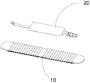
- FIG. 1 is a schematic structural view of a flexible electronic device according to an embodiment of the present invention.
- FIG. 2 is a schematic structural view of a deformation support assembly of the flexible electronic device of FIG. 1.
- FIG. 3 is a partially exploded view of the rotating unit of the deformation support assembly of FIG. 1.
- FIG. 5 is a partial structural schematic view of a rotating unit of the deformation support assembly of FIG. 2.
- Figure 6 is a partial cross-sectional view showing the rotating unit and the connecting member when the deformation supporting assembly is in a flat state.
- FIG. 7 is a second schematic structural diagram of a flexible electronic device according to an embodiment of the present invention.
- the flexible electronic device includes a functional component 20 and a deformation support assembly 10 disposed on an outer side of the deformation support assembly 10, and an inner side of the deformation support assembly 10 is adapted to be attached when the flexible electronic device is bent and deformed An external device.
- the functional component 20 is determined by a user using actual applications and functions of the flexible electronic device, which is a component having a display function when the flexible electronic device is used to display information, when the flexible electronic device is used for wireless communication
- the functional component 20 is a component having sound collection, playback, and wireless communication functions.
- the functional component 20 is a component including one or more sensors, when the flexible electronic device When used to play music, the functional component 20 is a component that includes an audio decoding chip and a player.
- the functional component 20 can be determined by a user using a practical application and function of the flexible electronic device, or can be determined by the user by an actual application and function of the flexible electronic device, for example, the flexible electronic device can be used to display information, and It can be used for both wireless communication, music playback, and data detection, and the functional component 20 corresponds to a collection of one or more functional components 20.
- the deformation supporting member 10 has a bending deformation function, and in the present embodiment, the generated shape becomes a shape that changes from a straight shape to a curved shape.
- the flexible electronic device When in a flat form, the flexible electronic device is spread out as a whole, thereby facilitating the user to use the functions of the flexible electronic device and perform man-machine operations.
- the flexible electronic device When in a curved configuration, the flexible electronic device is integrally crimped to form a wearable device, thereby facilitating the user to wear on the body.
- the shape of the deformation of the flexible electronic device can also be changed according to requirements to meet the needs of more applications. For example, switching from arch to circular, switching from flat to wavy, switching from U to S, and so on.
- the outer side surface of the deformation support assembly 10 is a flat surface.
- the outer side surface of the deformation support assembly 10 is a curved surface, and the deformation support assembly 10 is deformed.
- the inner side faces the bending direction, and the gathered inner side forms an accommodating space.
- the two ends of the deformation supporting assembly 10 cooperate with a clamping function, and the accommodating space can be used to mount or attach the flexible electronic device to an external device, for example,
- the flexible electronic device is attached to the user's wrist such that the flexible electronic device is worn on the user.
- the deformation support assembly 10 is in a flat configuration, the flexible electronic device can be removed from the user's wrist. Wherein, when the deformation support assembly 10 is bent and the two ends are in contact connection, the flexible electronic device forms a closed ring.
- the deformation support assembly 10 includes a plurality of rotary units 100 that are sequentially rotatably coupled to each other.
- the plurality of rotary units 100 are selectively coupled to each other to provide a curved deformation function of the deformation support assembly 10.
- the deformation support assembly 10 further includes a connector 200 that is rotatably coupled between the two rotation units 100 and, on the outside of the deformation support assembly 10,
- the surface area of the connecting member 200 is larger than the surface area of any one of the rotating units 100.
- the deformation support assembly 10 may be devoid of the connector 200 or include a plurality of connectors 200.
- the connector 200 is absent, the deformation surface of the deformation support assembly 10 is all determined by the rotation unit 100, and the deformation of the flexible electronic device The shape is adjustable.
- the functional component 20 is more easily disposed outside the deformation support assembly 10, thereby facilitating user operation and use.
- the deformation support assembly 10 further includes two movable members 300 rotatably coupled to the front and rear ends of the plurality of rotating units 100, wherein the outer side of the deformation support assembly 10 is
- the surface area of the movable member 300 is larger than the surface area of any one of the rotating units 100. .
- the provision of the movable member 300 will facilitate the user to convert the flexibility into a curved form from a straight form or a straight form from a curved form, and the movable member 300 is disposed on the deformation support.
- the surface area of the movable member 300 is larger than the surface area of any one of the rotating units 100, and the flexible electronic device can be prevented from being detached when attached to an external device.
- the deformation support assembly 10 includes a plurality of damper sheets 400 sandwiched between the rotation units 100 for rotational positioning of the rotation unit 100, and the damper sheet 400 is rotated when the user rotates the unit 100. And the maintenance of the curved shape after bending.
- the damping sheet 400 may be sandwiched between the rotating unit 100 and the connecting member 200. And between the rotating unit 100 and the movable member 300 for positioning when the flexible electronic device is bent and deformed.
- each of the rotating units 100 includes a substrate 120 and a support base 140 extending outward from the substrate 120.
- the support base 140 includes a rotating arm 144 and
- the rotating seat 142 is sleeved with the rotating seat 142 on the support base 140 of the adjacent rotating unit 100.
- the outer edge of the rotating seat 142 of each support seat 140 abuts against the adjacent support base 140.
- the pedestals of each of the rotating units 100 are spliced together to form a splicing surface, and the supporting seats 140 of each rotating unit 100 are arranged in a row.
- All of the rotating unit 100 support seats 140 include a rotating arm 144 and a rotating base 142 in series.
- each of the rotating units 100 includes two supporting bases 140 extending vertically upward on the substrate 120 and perpendicularly connected to the substrate 120.
- the two supporting bases 140 are symmetrically disposed on the substrate 120.
- Each of the support bases 140 includes a rotating arm 144 and a rotating base 142, respectively.
- the two supporting bases 140 of each rotating unit 100 are respectively arranged in a row.
- the two support bases 140 of all the rotating units 100 include a rotating arm 144 and a rotating base 142 connected in series. Providing two support seats is advantageous for improving the connection strength and stability when the rotary unit 100 is rotationally coupled.
- each of the rotating units 100 further includes a bolt 500.
- the rotating arm 144 is provided with a rotating hole 148.
- the rotating base 142 has a groove, and the groove is symmetrically disposed on both sides.
- 146 when the rotating arm 144 is sleeved with the rotating base 142 on the supporting base 140 of the adjacent rotating unit 100, the rotating arm 144 is partially received in a groove of the rotating base of the adjacent rotating unit, and the bolt 500 passes through The through hole 146 and the rotating hole 148.
- the damper sheet 400 is clamped between the rotating arm 144 of the adjacent rotating unit and the groove of the rotating base 142.
- the damper sheet 400 can be arranged to facilitate the user to control the bending strength of the flexible electronic device according to the actual use scenario.
- the rotating hole 148 is circular, elliptical or polygonal with a plurality of corners. Referring to FIG. 3, FIG. 4 and FIG. 6, in the embodiment, the rotating hole 148 is elliptical, and the bolt 500 is The rotating hole 148 is slidably sleeved, and when the rotating unit 100 is rotatably connected with the adjacent rotating unit, the outer edge of the rotating base 142 abuts on the outer edge of the rotating base 142 of the adjacent rotating unit 100, the rotating arm One end of the 144 abuts against the inner wall of the groove of the rotating base 142 of the adjacent rotating unit.
- the rotating seat 142 is rounded away from the end of the substrate 120, and the rotating arm 144 is abutted to the end of the inner wall of the groove of the adjacent rotating base 142.
- the rotating hole 148 is elliptical, the rotating arm 144 of the rotating unit 100 has a moving space when rotated in the rotating base 142, so that the rotating arm 144 can move in the direction of the diagonal in the rotating space while rotating, thereby making the flexible electronic
- the device achieves bending deformation.
- Cooperating with the outer edge of the rounded transition of the rotating base 142 the flexible electronic device is more compliant in bending deformation.
- the outer edge of the angular rotation base 142 can control the rotation range of the two rotation units 100.
- the rotation angle between the two rotation units 100 is limited to 1 degree or more and 5 degrees or less.
- the connecting member 200 and the movable member 300 are also provided with corresponding rotating structures rotatably coupled with the rotating arm 144 and the rotating base 142 on the rotating unit 100.
- the rotating structure and the rotating unit on the connecting member 200 and the movable member 300 The rotating arm 144 of the 100 is the same as the rotating base 142.
- the rotating structure of the connecting member 200 and the movable member 300 has one rotating arm, the rotating structure and the rotating base 142 of the rotating unit 100 of the first end or the end of the rotating unit 100 are rotatably connected.
- Rotating connection when the rotating structure of the connecting member 200 and the movable member 300 has a rotating seat, the rotating structure and the rotating arm 144 of the rotating unit 100 of the head end or the end of the rotating unit 100 are rotatably connected, the connecting member 200 and the movable portion
- the rotating structure on the member 300 and the rotating arm 144 and the rotating seat 142 of the rotating unit 100 are also directly provided with the damping sheet 400 as well.
- the deformation support assembly 10 further includes a spring 50 , and the rotating unit 100 , the connecting member 200 and the movable member 300 are attached to one side of the elastic piece 50 .
- the provision of the shrapnel 50 enhances the strength of the deformed support assembly 10, controls the bending strength of the deformed support assembly 10, and facilitates the mounting and placement of the functional assembly 20.
- the functional component 20 is a flexible touch screen, and the flexible screen is attached to the other side of the elastic piece 50.
- the functional elements are not limited to flexible touch screens, but may also include other kinds of functional elements, such as other types of functional components 20/indicia screens, function sensors, speakers, microphones, etc., depending on different needs.
- Other types of functional components 20/indicating screens can be hard functional components 20 of various areas, electronic ink screens, LED lighting panels, etc., which can be secured to the top surface of the support panel 34.
- Functional sensors may include body temperature sensors, temperature sensors, speed sensors, gravity sensors, height sensors, angular velocity sensors, acceleration sensors, air pressure sensors, heart rate sensors, pulse sensors, sweat sensors, light sensors, An electromyographic sensor or the like, which can be disposed at various positions of the flexible electronic device according to different purposes of use.
- the flexible electronic device further includes a flexible housing 30 having a hollow chamber 32 and a cover plate 34, the cover plate 34 having a transparent area, the functional component 20 and the deformation support
- the assembly 10 is housed in a hollow chamber of the housing 30, and the flexible touch screen 20 faces the transparent area.
- the flexible electronic device also includes an electronic component 40 that is received within the hollow cavity of the flexible housing 30.
- the electronic component 40 includes a battery, a microphone, a circuit board, and a speaker, and the battery, the microphone, the circuit board, and the speaker are disposed on one side of the movable member 300.
- the electronic components 40 include a battery, a microphone, a circuit board, and a speaker, the battery, the microphone, the circuit board, and the speaker are disposed in the room.
- the side of the movable member 300 can effectively save the internal space of the flexible electronic device, making the flexible electronic device thinner and lighter.
Landscapes
- Engineering & Computer Science (AREA)
- Theoretical Computer Science (AREA)
- General Engineering & Computer Science (AREA)
- Computer Hardware Design (AREA)
- Human Computer Interaction (AREA)
- Physics & Mathematics (AREA)
- General Physics & Mathematics (AREA)
- Computer Networks & Wireless Communication (AREA)
- Signal Processing (AREA)
- Telephone Set Structure (AREA)
- Casings For Electric Apparatus (AREA)
- Devices For Indicating Variable Information By Combining Individual Elements (AREA)
Abstract
Description
Claims (16)
- 一种柔性电子装置,其特征在于,包括功能组件和形变支撑组件,所述功能组件设置于所述形变支撑组件的外侧,所述形变支撑组件的内侧用于在所述柔性电子装置弯曲变形时贴合一外部装置。
- 如权利要求1所述的柔性电子装置,其特征在于,所述形变支撑组件包括若干个旋转单元,相邻旋转单元依次可旋转地连接。
- 如权利要求2所述的柔性电子装置,其特征在于,所述形变支撑组件还包括至少一个连接件,所述连接件旋转连接于所述两个旋转单元之间,并且,在所述形变支撑组件的外侧,所述连接件的表面积大于所述任一一个旋转单元的表面积。
- 如权利要求3所述的柔性电子装置,其特征在于,所述形变支撑组件还包括两个活动件,所述两个活动件旋转连接于所述若干个旋转单元的首尾两端,其中,在所述形变支撑组件的外侧,所述活动件的表面积大于所述任一一个旋转单元的表面积。
- 如权利要求4所述的柔性电子装置,其特征在于,所述形变支撑组件还包括若干个阻尼片,各阻尼片夹持于所述旋转单元和所述连接件之间或/和所述旋转单元和至少一个活动件之间,用于所述柔性电子装置弯曲变形时定位。
- 如权利要求5所述的柔性电子装置,其特征在于,所述阻尼片夹持于相邻旋转单元的旋转臂与旋转座凹槽之间。
- 如权利要求2至6任一项所述的柔性电子装置,其特征在于,所述每个 旋转单元包括基板和自所述基板向外延伸的支撑座,所述支撑座上包括旋转臂和旋转座,所述旋转臂和相邻旋转单元的支撑座上的旋转座套接。
- 如权利要求7所述的柔性电子装置,其特征在于,所述每个旋转单元还包括螺栓,所述旋转臂上设有旋转孔,所述旋转座具有凹槽,所述凹槽两侧对称设有贯孔,所述旋转臂和相邻旋转单元支撑座上的旋转座套接时,所述旋转臂部分收纳于相邻旋转单元旋转座的凹槽中,所述螺栓穿过所述贯孔和所述旋转孔。
- 如权利要求8所述的柔性电子装置,其特征在于,所述每个旋转单元包括基板和与两个所述支撑座,所述两个支撑座设置在所述基板相对两侧上。
- 如权利要求8所述的柔性电子装置,其特征在于,所述旋转孔为圆形、椭圆形或者具有多个棱角的多边形,所述螺栓与所述旋转孔滑动套接,当所述旋转单元与相邻的旋转单元旋转连接时,所述旋转座外缘抵持于相邻旋转单元旋转座的外缘上,所述旋转臂的一端抵持于相邻旋转单元旋转座的凹槽内壁。
- 如权利要求10所述的柔性电子装置,其特征在于,所述旋转座远离基板的一端圆角过渡,所述旋转臂抵持于相邻旋转座凹槽内壁的一端圆角过渡。
- 如权利要求11所述的柔性电子装置,其特征在于,所述柔性电子装置还包括弹片,所述旋转单元、连接件以及活动件贴合于所述弹片一侧。
- 如权利要求12所述的柔性电子装置,其特征在于,所述功能组件为柔性触控屏,所述柔性触控屏贴合于所述弹片另一侧。
- 如权利要求13所述的柔性电子装置,其特征在于,所述柔性电子装置还包括柔性壳体,所述柔性壳体包括中空腔室和透明盖板,所述盖板具有透明区域,所述功能组件和形变支撑组件收纳于所述壳体的中空腔室内,所述柔性触控屏正对所述盖板的透明区域。
- 如权利要求14所述的柔性电子装置,其特征在于,所述柔性电子装置还包括电子组件,所述电子组件容置于所述柔性壳体的中空腔室内。
- 如权利要求15所述的柔性电子装置,其特征在于,所述电子组件包括电池、麦克风、电路板和扬声器,所述电池、麦克风、电路板和扬声器设置于所述活动件一侧。
Priority Applications (7)
| Application Number | Priority Date | Filing Date | Title |
|---|---|---|---|
| US16/465,872 US20190302837A1 (en) | 2016-12-06 | 2016-12-06 | Flexible electronic device |
| CA3044881A CA3044881A1 (en) | 2016-12-06 | 2016-12-06 | Flexible electronic device |
| JP2019530146A JP2020507795A (ja) | 2016-12-06 | 2016-12-06 | フレキシブルデバイス |
| PCT/CN2016/108747 WO2018102997A1 (zh) | 2016-12-06 | 2016-12-06 | 一种柔性电子装置 |
| EP16923550.4A EP3553955A4 (en) | 2016-12-06 | 2016-12-06 | FLEXIBLE ELECTRONIC DEVICE |
| CN201680031927.9A CN107734992B (zh) | 2016-12-06 | 2016-12-06 | 柔性电子装置 |
| KR1020197018009A KR20190089180A (ko) | 2016-12-06 | 2016-12-06 | 플렉서블 디바이스 |
Applications Claiming Priority (1)
| Application Number | Priority Date | Filing Date | Title |
|---|---|---|---|
| PCT/CN2016/108747 WO2018102997A1 (zh) | 2016-12-06 | 2016-12-06 | 一种柔性电子装置 |
Publications (1)
| Publication Number | Publication Date |
|---|---|
| WO2018102997A1 true WO2018102997A1 (zh) | 2018-06-14 |
Family
ID=61201708
Family Applications (1)
| Application Number | Title | Priority Date | Filing Date |
|---|---|---|---|
| PCT/CN2016/108747 Ceased WO2018102997A1 (zh) | 2016-12-06 | 2016-12-06 | 一种柔性电子装置 |
Country Status (7)
| Country | Link |
|---|---|
| US (1) | US20190302837A1 (zh) |
| EP (1) | EP3553955A4 (zh) |
| JP (1) | JP2020507795A (zh) |
| KR (1) | KR20190089180A (zh) |
| CN (1) | CN107734992B (zh) |
| CA (1) | CA3044881A1 (zh) |
| WO (1) | WO2018102997A1 (zh) |
Cited By (1)
| Publication number | Priority date | Publication date | Assignee | Title |
|---|---|---|---|---|
| CN109090755A (zh) * | 2018-08-30 | 2018-12-28 | 歌尔科技有限公司 | 一种穿戴装置及具有该穿带装置的头戴设备 |
Families Citing this family (48)
| Publication number | Priority date | Publication date | Assignee | Title |
|---|---|---|---|---|
| CN108551499B (zh) * | 2018-03-05 | 2020-12-18 | 努比亚技术有限公司 | 一种显示终端 |
| CN110554737B (zh) * | 2018-05-31 | 2023-01-20 | 努比亚技术有限公司 | 一种链节组件及其终端 |
| CN110557165A (zh) * | 2018-05-31 | 2019-12-10 | 努比亚技术有限公司 | 一种连接结构和终端 |
| CN110554735B (zh) * | 2018-05-31 | 2023-04-14 | 努比亚技术有限公司 | 一种连接链节组件及可穿戴设备 |
| CN110557164A (zh) * | 2018-05-31 | 2019-12-10 | 努比亚技术有限公司 | 一种连接结构和终端 |
| CN110547563B (zh) * | 2018-05-31 | 2021-10-12 | 努比亚技术有限公司 | 一种链条组件和终端 |
| CN110557475A (zh) * | 2018-05-31 | 2019-12-10 | 努比亚技术有限公司 | 一种弯折限位链及终端 |
| CN110554736A (zh) * | 2018-05-31 | 2019-12-10 | 努比亚技术有限公司 | 一种终端 |
| CN109495610A (zh) * | 2018-05-31 | 2019-03-19 | 努比亚技术有限公司 | 终端及其组装方法 |
| CN108832952A (zh) * | 2018-05-31 | 2018-11-16 | 努比亚技术有限公司 | 一种可穿戴设备、蓝牙连接方法及计算机可读存储介质 |
| CN110547562B (zh) * | 2018-05-31 | 2021-06-01 | 努比亚技术有限公司 | 一种链节组件及终端 |
| CN110547568A (zh) * | 2018-05-31 | 2019-12-10 | 努比亚技术有限公司 | 一种连接结构和终端 |
| CN110547565A (zh) * | 2018-05-31 | 2019-12-10 | 努比亚技术有限公司 | 一种连接结构和终端 |
| CN110547556B (zh) * | 2018-05-31 | 2021-06-25 | 努比亚技术有限公司 | 一种链条组件及终端 |
| CN110547555B (zh) * | 2018-05-31 | 2021-12-24 | 努比亚技术有限公司 | 一种链节组件及其穿戴设备 |
| CN110557476A (zh) * | 2018-05-31 | 2019-12-10 | 努比亚技术有限公司 | 一种终端 |
| CN110554767B (zh) * | 2018-05-31 | 2025-02-18 | 努比亚技术有限公司 | 一种终端 |
| CN110547557A (zh) * | 2018-05-31 | 2019-12-10 | 努比亚技术有限公司 | 一种连接链节组件、表带及可穿戴设备 |
| CN110547566B (zh) * | 2018-05-31 | 2021-09-17 | 努比亚技术有限公司 | 一种连接结构 |
| CN110547567A (zh) * | 2018-05-31 | 2019-12-10 | 努比亚技术有限公司 | 一种链条组件及终端 |
| CN110215022A (zh) * | 2019-04-30 | 2019-09-10 | 努比亚技术有限公司 | 一种表带和可穿戴设备 |
| CN110122986A (zh) * | 2019-04-30 | 2019-08-16 | 努比亚技术有限公司 | 一种表带和可穿戴设备 |
| CN110141023A (zh) * | 2019-04-30 | 2019-08-20 | 努比亚技术有限公司 | 一种表带和可穿戴设备 |
| CN110301728B (zh) * | 2019-06-28 | 2021-05-14 | 努比亚技术有限公司 | 一种链节组件和可穿戴设备 |
| CN110448020B (zh) * | 2019-06-28 | 2021-10-15 | 努比亚技术有限公司 | 一种可穿戴设备 |
| CN110432605A (zh) * | 2019-06-28 | 2019-11-12 | 努比亚技术有限公司 | 一种链条组件及可穿戴设备 |
| CN110448019A (zh) * | 2019-06-28 | 2019-11-15 | 努比亚技术有限公司 | 一种链条组件和可穿戴设备 |
| TWI751461B (zh) * | 2019-12-16 | 2022-01-01 | 仁寶電腦工業股份有限公司 | 穿戴式生理訊號偵測裝置 |
| CN111188972B (zh) * | 2020-02-28 | 2022-01-18 | 联想(北京)有限公司 | 屏幕支架及电子设备 |
| CN114439843A (zh) * | 2020-10-31 | 2022-05-06 | 华为技术有限公司 | 柔性屏支撑机构及可卷曲的电子设备 |
| USD952773S1 (en) * | 2020-11-17 | 2022-05-24 | Hongdan Chen | Silicone weight bracelet |
| CN112991946B (zh) | 2021-02-23 | 2023-04-07 | 京东方科技集团股份有限公司 | 显示面板和显示装置 |
| CN113114814B (zh) * | 2021-04-09 | 2023-05-16 | 维沃移动通信有限公司 | 一种电子设备 |
| CN113494666B (zh) * | 2021-07-07 | 2023-01-24 | 京东方科技集团股份有限公司 | 支撑结构和显示装置 |
| USD1033575S1 (en) * | 2022-06-14 | 2024-07-02 | Laura M Jury | Weight bars bracelet |
| CN115729088A (zh) * | 2022-08-23 | 2023-03-03 | 维沃移动通信有限公司 | 智能手表 |
| CN115410488B (zh) * | 2022-09-23 | 2025-11-18 | 维沃移动通信有限公司 | 电子设备 |
| CN115899485B (zh) * | 2022-12-22 | 2024-11-15 | 京东方科技集团股份有限公司 | 显示装置 |
| USD1018734S1 (en) * | 2023-07-14 | 2024-03-19 | Jianjun Yan | Wrist weight |
| USD1018735S1 (en) * | 2023-07-14 | 2024-03-19 | Jianjun Yan | Wrist weight |
| CN116887553B (zh) * | 2023-09-07 | 2023-12-19 | 深圳市格林兴显示科技有限公司 | 一种可折叠显示器 |
| USD1048248S1 (en) * | 2023-09-15 | 2024-10-22 | Dequan ZHANG | Wrist weight |
| CN117392916A (zh) * | 2023-09-26 | 2024-01-12 | 深圳创维-Rgb电子有限公司 | 曲直变形显示设备 |
| CN220937036U (zh) * | 2023-09-26 | 2024-05-14 | 张德权 | 一种负重手环 |
| USD1036586S1 (en) * | 2024-04-02 | 2024-07-23 | Mengquan Chen | Weighted exercise band |
| USD1039628S1 (en) * | 2024-04-11 | 2024-08-20 | Xiamen Shuohui Trading Co., Ltd. | Wrist ankle weights |
| USD1048249S1 (en) * | 2024-08-07 | 2024-10-22 | Xiamen Haochu Silicone Rubber Products Co., Ltd. | Silicone weighted bracelet |
| CN119572895B (zh) * | 2025-02-10 | 2025-04-18 | 福建艾瑞科电子有限公司 | 一种柔性屏支撑装置及智能传媒设备 |
Citations (4)
| Publication number | Priority date | Publication date | Assignee | Title |
|---|---|---|---|---|
| CN103546181A (zh) * | 2012-07-17 | 2014-01-29 | 高寿谦 | 可拆卸并可自由组合功能的穿戴式无线智能电子装置 |
| KR20140077807A (ko) * | 2012-12-14 | 2014-06-24 | 이유구 | 가요성표시소자를 구비한 휴대용 모바일기기 |
| CN105492817A (zh) * | 2014-12-30 | 2016-04-13 | 深圳市柔宇科技有限公司 | 一种形态可变的支撑结构及具有该结构的电子设备 |
| CN105763684A (zh) * | 2016-04-21 | 2016-07-13 | 重庆墨希科技有限公司 | 可穿戴式柔性手机及履带式壳体 |
Family Cites Families (19)
| Publication number | Priority date | Publication date | Assignee | Title |
|---|---|---|---|---|
| JPS5216769Y2 (zh) * | 1971-05-06 | 1977-04-15 | ||
| JPH0334094Y2 (zh) * | 1985-06-12 | 1991-07-19 | ||
| JPH0737526Y2 (ja) * | 1989-11-30 | 1995-08-30 | 並木精密宝石株式会社 | 腕時計用バンド |
| JP2002101922A (ja) * | 2000-07-28 | 2002-04-09 | Shinwa:Kk | 硬質バンドのバンド駒等の連結構造 |
| CH699811B1 (fr) * | 2000-08-11 | 2010-05-14 | Rado Montres Sa | Bracelet à maillons articulés et procédé d'assemblage d'un tel bracelet |
| JP2002360318A (ja) * | 2001-06-05 | 2002-12-17 | Seiko Epson Corp | 連結構造及びそれを用いた時計 |
| US6418706B1 (en) * | 2001-11-27 | 2002-07-16 | Fossil, Inc. | Watchband link assembly |
| DE10257439A1 (de) * | 2001-12-21 | 2003-09-18 | Seiko Instr Inc | Tragbares elektronisches Gerät |
| CN2785412Y (zh) * | 2005-05-30 | 2006-06-07 | 创意(保捷)国际有限公司 | 塑料链形连接件 |
| CN201029503Y (zh) * | 2007-02-07 | 2008-03-05 | 石华平 | 不受力手表表带 |
| HK1166922A2 (zh) * | 2011-09-01 | 2012-11-09 | 得利钟表制品厂有限公司 | 具有可见销的表带 |
| KR102014445B1 (ko) * | 2013-09-27 | 2019-08-29 | 삼성전자주식회사 | 착용형 기기 |
| WO2015100396A1 (en) * | 2013-12-24 | 2015-07-02 | Polyera Corporation | Support structures for a flexible electronic component |
| KR20160103072A (ko) * | 2013-12-24 | 2016-08-31 | 폴리에라 코퍼레이션 | 가요성 전자 부품용 지지 구조체 |
| KR101722447B1 (ko) * | 2014-04-18 | 2017-04-04 | (주) 프렉코 | 가이드시트가 연동되는 플렉시블 디스플레이 단말기 |
| US9612623B2 (en) * | 2014-09-16 | 2017-04-04 | Lg Electronics Inc. | Mobile terminal |
| CN104714699A (zh) * | 2015-04-13 | 2015-06-17 | 京东方科技集团股份有限公司 | 柔性显示装置 |
| CN105700841B (zh) * | 2016-01-11 | 2021-12-24 | 联想(北京)有限公司 | 一种柔性电子设备 |
| CN105915680B (zh) * | 2016-06-24 | 2019-02-05 | 重庆墨希科技有限公司 | 柔性防尘智能手机及柔性壳体 |
-
2016
- 2016-12-06 JP JP2019530146A patent/JP2020507795A/ja active Pending
- 2016-12-06 WO PCT/CN2016/108747 patent/WO2018102997A1/zh not_active Ceased
- 2016-12-06 CA CA3044881A patent/CA3044881A1/en not_active Abandoned
- 2016-12-06 KR KR1020197018009A patent/KR20190089180A/ko not_active Ceased
- 2016-12-06 EP EP16923550.4A patent/EP3553955A4/en not_active Withdrawn
- 2016-12-06 US US16/465,872 patent/US20190302837A1/en not_active Abandoned
- 2016-12-06 CN CN201680031927.9A patent/CN107734992B/zh not_active Expired - Fee Related
Patent Citations (4)
| Publication number | Priority date | Publication date | Assignee | Title |
|---|---|---|---|---|
| CN103546181A (zh) * | 2012-07-17 | 2014-01-29 | 高寿谦 | 可拆卸并可自由组合功能的穿戴式无线智能电子装置 |
| KR20140077807A (ko) * | 2012-12-14 | 2014-06-24 | 이유구 | 가요성표시소자를 구비한 휴대용 모바일기기 |
| CN105492817A (zh) * | 2014-12-30 | 2016-04-13 | 深圳市柔宇科技有限公司 | 一种形态可变的支撑结构及具有该结构的电子设备 |
| CN105763684A (zh) * | 2016-04-21 | 2016-07-13 | 重庆墨希科技有限公司 | 可穿戴式柔性手机及履带式壳体 |
Non-Patent Citations (1)
| Title |
|---|
| See also references of EP3553955A4 * |
Cited By (2)
| Publication number | Priority date | Publication date | Assignee | Title |
|---|---|---|---|---|
| CN109090755A (zh) * | 2018-08-30 | 2018-12-28 | 歌尔科技有限公司 | 一种穿戴装置及具有该穿带装置的头戴设备 |
| CN109090755B (zh) * | 2018-08-30 | 2024-05-28 | 歌尔科技有限公司 | 一种穿戴装置及具有该穿带装置的头戴设备 |
Also Published As
| Publication number | Publication date |
|---|---|
| EP3553955A1 (en) | 2019-10-16 |
| JP2020507795A (ja) | 2020-03-12 |
| CN107734992A (zh) | 2018-02-23 |
| EP3553955A4 (en) | 2020-06-24 |
| CA3044881A1 (en) | 2018-06-14 |
| CN107734992B (zh) | 2020-07-28 |
| US20190302837A1 (en) | 2019-10-03 |
| KR20190089180A (ko) | 2019-07-30 |
Similar Documents
| Publication | Publication Date | Title |
|---|---|---|
| WO2018102997A1 (zh) | 一种柔性电子装置 | |
| CN107690304B (zh) | 柔性装置 | |
| JP6706683B2 (ja) | フレキシブルデバイス | |
| USD541278S1 (en) | Display device capable of receiving an electronic device | |
| WO2018014196A1 (zh) | 柔性装置 | |
| ES2744233T3 (es) | Procedimiento de fabricación de una carcasa exterior y dispositivo electrónico que comprende la misma | |
| US20180173275A1 (en) | Expandable Grip With Wireless Communication Module | |
| CN109841152A (zh) | 电子装置和可折叠显示装置 | |
| HK1077972A2 (zh) | 带音响的眼镜 | |
| CN116517950B (zh) | 一种转轴机构、支撑装置和折叠屏设备 | |
| CN116848957A (zh) | 包括散热结构的可穿戴电子装置 | |
| WO2020187030A1 (zh) | 壳体、中框及电子设备 | |
| US20150063623A1 (en) | Headphone device | |
| CN212814797U (zh) | 表带及具有该表带的智能手表 | |
| KR20210014030A (ko) | 스피커 어셈블리를 포함하는 전자 장치 | |
| JP6152410B1 (ja) | 電子機器 | |
| JP3124295U (ja) | 音楽が放送可能な機能を持つめがね | |
| CN205123950U (zh) | 具有声控功能的智能型麦克风 | |
| WO2020215559A1 (zh) | 一种多轴手机折叠支架 | |
| WO2020224211A1 (zh) | 一种具有可弯折显示屏的智能主机及穿戴设备 | |
| CN223859226U (zh) | 耳机单元及耳机 | |
| CN210490981U (zh) | 一种带有指环扣的手机保护壳 | |
| CN214711819U (zh) | 一种舞蹈用便于安装的全身镜 | |
| CN106454565A (zh) | 具有声控功能的智能型麦克风 | |
| TWI593293B (zh) | 具有聲控功能的智慧型麥克風 |
Legal Events
| Date | Code | Title | Description |
|---|---|---|---|
| 121 | Ep: the epo has been informed by wipo that ep was designated in this application |
Ref document number: 16923550 Country of ref document: EP Kind code of ref document: A1 |
|
| ENP | Entry into the national phase |
Ref document number: 3044881 Country of ref document: CA |
|
| ENP | Entry into the national phase |
Ref document number: 2019530146 Country of ref document: JP Kind code of ref document: A |
|
| NENP | Non-entry into the national phase |
Ref country code: DE |
|
| ENP | Entry into the national phase |
Ref document number: 20197018009 Country of ref document: KR Kind code of ref document: A |
|
| ENP | Entry into the national phase |
Ref document number: 2016923550 Country of ref document: EP Effective date: 20190708 |