WO2018105303A1 - アンテナ装置 - Google Patents
アンテナ装置 Download PDFInfo
- Publication number
- WO2018105303A1 WO2018105303A1 PCT/JP2017/040471 JP2017040471W WO2018105303A1 WO 2018105303 A1 WO2018105303 A1 WO 2018105303A1 JP 2017040471 W JP2017040471 W JP 2017040471W WO 2018105303 A1 WO2018105303 A1 WO 2018105303A1
- Authority
- WO
- WIPO (PCT)
- Prior art keywords
- section
- feed line
- feed
- radiating elements
- antenna device
- Prior art date
- Legal status (The legal status is an assumption and is not a legal conclusion. Google has not performed a legal analysis and makes no representation as to the accuracy of the status listed.)
- Ceased
Links
Images




Classifications
-
- H—ELECTRICITY
- H01—ELECTRIC ELEMENTS
- H01Q—ANTENNAS, i.e. RADIO AERIALS
- H01Q21/00—Antenna arrays or systems
- H01Q21/0006—Particular feeding systems
- H01Q21/0031—Parallel-plate fed arrays; Lens-fed arrays
-
- H—ELECTRICITY
- H01—ELECTRIC ELEMENTS
- H01P—WAVEGUIDES; RESONATORS, LINES, OR OTHER DEVICES OF THE WAVEGUIDE TYPE
- H01P5/00—Coupling devices of the waveguide type
- H01P5/12—Coupling devices having more than two ports
-
- H—ELECTRICITY
- H01—ELECTRIC ELEMENTS
- H01Q—ANTENNAS, i.e. RADIO AERIALS
- H01Q15/00—Devices for reflection, refraction, diffraction or polarisation of waves radiated from an antenna, e.g. quasi-optical devices
- H01Q15/02—Refracting or diffracting devices, e.g. lens, prism
-
- H—ELECTRICITY
- H01—ELECTRIC ELEMENTS
- H01Q—ANTENNAS, i.e. RADIO AERIALS
- H01Q21/00—Antenna arrays or systems
- H01Q21/0006—Particular feeding systems
-
- H—ELECTRICITY
- H01—ELECTRIC ELEMENTS
- H01Q—ANTENNAS, i.e. RADIO AERIALS
- H01Q21/00—Antenna arrays or systems
- H01Q21/06—Arrays of individually energised antenna units similarly polarised and spaced apart
-
- H—ELECTRICITY
- H01—ELECTRIC ELEMENTS
- H01Q—ANTENNAS, i.e. RADIO AERIALS
- H01Q25/00—Antennas or antenna systems providing at least two radiating patterns
- H01Q25/007—Antennas or antenna systems providing at least two radiating patterns using two or more primary active elements in the focal region of a focusing device
- H01Q25/008—Antennas or antenna systems providing at least two radiating patterns using two or more primary active elements in the focal region of a focusing device lens fed multibeam arrays
-
- H—ELECTRICITY
- H01—ELECTRIC ELEMENTS
- H01Q—ANTENNAS, i.e. RADIO AERIALS
- H01Q13/00—Waveguide horns or mouths; Slot antennas; Leaky-waveguide antennas; Equivalent structures causing radiation along the transmission path of a guided wave
- H01Q13/20—Non-resonant leaky-waveguide or transmission-line antennas; Equivalent structures causing radiation along the transmission path of a guided wave
- H01Q13/206—Microstrip transmission line antennas
Definitions
- the present invention relates to a high-speed transmission wireless communication technology.
- the Rotman lens includes a planar pattern, a curved surface, a beam port for feeding power, and an array port connected to a radiation element. The Rotman lens can change the radiation direction of the beam in a wide band because the time delay amount between the array ports changes by changing the beam port to be fed.
- Non-Patent Document 2 When a series feed array antenna having a feed point at one end of a feed line is connected to a Rotman lens as in Non-Patent Document 2, the radiation depends on the frequency of electromagnetic waves radiated from the series feed array antenna. There has been a problem that the peak direction of the radiation pattern is changed.
- the present invention has been made in view of the above problems, and an object of the present invention is to realize an antenna device including a Rotman lens, in which the peak direction of the radiation pattern does not depend on the frequency of the electromagnetic wave radiated. For the purpose.
- an antenna device includes a ground layer made of a conductor, a plurality of array antennas provided above the ground layer and separated from the ground layer, An antenna device comprising a Rotman lens provided below the ground layer and spaced from the ground layer, wherein each of the plurality of array antennas includes a feed line having a feed point located at the center thereof, A plurality of radiating elements connected to the feed line, and has a point-symmetric shape with the feed point as the center of symmetry, and each of the feed points of the plurality of array antennas is formed on the ground layer It is connected to an end portion of one of the output ports of the Rotman lens through a slot.
- the antenna device is an antenna device including a Rotman lens, and can realize an antenna device in which the peak direction of the radiation pattern does not depend on the frequency of the electromagnetic wave radiated.
- FIG. 2 is a top view of the array antenna with which the beam forming antenna shown in FIG. 2 is provided.
- B is an enlarged plan view of the array antenna shown in (a).
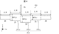
- FIG. 4 is a plan view of a branch section of the array antenna shown in FIG. 3. It is a top view of the Rotman lens with which the beam forming antenna shown in FIG. 2 is provided. It is a disassembled perspective view of the beam forming antenna which concerns on the 2nd Embodiment of this invention.
- FIG. 7B is a plan view of a Rotman lens provided in the beam forming antenna shown in FIG. (C) is an enlarged view of one of the output ports provided in the Rotman lens shown in (b).
- (A) is the azimuth
- (B) is the azimuth
- a beamforming antenna includes a ground layer, a plurality of array antennas, and a Rotman lens.
- the ground layer is composed of a film or a plate made of a conductor.
- the plurality of array antennas are provided above the ground layer and separated from the ground layer.
- the Rotman lens is provided below the ground layer and separated from the ground layer.
- the ground layer is indicated by an imaginary line (two-dot chain line) for easy viewing of the perspective view.
- illustration of a plurality of slots provided with a ground layer is omitted. Details of the plurality of slots will be described later with reference to FIGS. 2 and 3A and FIGS. 6 and 7A.
- Each slot is provided in a region where the end of the output port of the Rotman lens and the feeding point of the array antenna overlap when the beam forming antenna is viewed in plan.
- Each of the plurality of array antennas includes a feed line in which the feed point is located at the center thereof, and a plurality of radiating elements connected to the feed line, and has a point-symmetric shape with the feed point as the center of symmetry. (See (a) of FIG. 3 and (a) of FIG. 7).
- Each of the feeding points of the plurality of array antennas is coupled to the end of one of the output ports of the Rotman lens via a slot formed in the ground layer (FIGS. 2, 3A, 6). And (a) of FIG. 7).
- such a beam forming antenna includes, for example, a dielectric substrate composed of a ground layer and two dielectric layers (a first dielectric layer and a second dielectric layer) sandwiching the ground layer.
- a dielectric substrate composed of a ground layer and two dielectric layers (a first dielectric layer and a second dielectric layer) sandwiching the ground layer.
- a plurality of array antennas may be formed on the front surface of the dielectric substrate, and a Rotman lens may be formed on the back surface of the dielectric substrate.
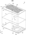
- FIG. 2 is an exploded perspective view of the beamforming antenna 1 according to the present embodiment.
- FIG. 3A is a plan view of an array antenna 22i that is one of a plurality of array antennas 22 included in the beamforming antenna 1.
- FIG. 3B is an enlarged plan view of the array antenna 22i shown in FIG. 3A, and is an enlarged plan view of the region R1 shown in FIG. 4 is a plan view of a branching portion of the array antenna 22i shown in FIG.
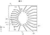
- FIG. 5 is a plan view of the Rotman lens 32 provided in the beam forming antenna 1.
- FIG. 9 shows an exploded perspective view of the series-feed array antenna described in Non-Patent Document 2 (hereinafter, the conventional beam forming antenna 101).
- the conventional beam forming antenna 101 includes a ground layer 141, a dielectric layer 121, a plurality of array antennas 122, a dielectric layer 131, and a Rotman lens 132, as shown in FIG.
- the Rotman lens 132 includes a plurality of power supply ports 1321, a plurality of output ports 1322, and a main body 1323.
- a plurality of slots 1141 are provided in the ground layer 141.
- One end of each of the plurality of output ports 1322 of the Rotman lens 132 (the end opposite to the main body 1323) and a feeding point that is one end of the plurality of array antennas 122 form a plurality of slots 1141.
- FIG. 9 virtually shows the surface on which the plurality of array antennas 122 are formed and the surface on which the Rotman lens 132 is formed.
- the plurality of array antennas 122 and one main surface of the dielectric layer 121 are drawn so as to be separated from each other. However, actually, the plurality of array antennas 122 are stacked on one main surface of the dielectric layer 121. The same applies to the Rotman lens 132.
- the beam forming antenna 1 which is one aspect of the antenna device described in the claims includes a ground layer 11, a dielectric layer 21, a plurality of array antennas 22, and a dielectric layer 31. And a Rotman lens 32.
- the direction along the normal line of the main surface 211 of the dielectric layer 21 is defined as the z-axis direction, and a feed line 23Li (see FIG. 3) of each array antenna 22i described later is extended.
- the direction is defined as the x-axis direction
- the y-axis direction is defined so as to form a right-handed orthogonal coordinate system together with the x-axis direction and the z-axis direction.
- a direction from the main surface 212 to the main surface 211 in the z-axis direction is defined as a z-axis positive direction
- a direction from a plurality of output ports 322 of a Rotman lens 32 described later to a plurality of power supply ports 321 is defined as an x-axis positive direction.
- the y-axis positive direction is determined so as to constitute a right-handed orthogonal coordinate system together with the x-axis positive direction and the z-axis positive direction.
- the ground layer 11 and the dielectric layers 21 and 31 that are a pair of dielectric layers sandwiching the ground layer 11 constitute a dielectric substrate.
- the main surface 211 that is one main surface (the main surface on the z-axis positive direction side) of the dielectric layer 21 constitutes the front surface of the dielectric substrate, and the other main surface (z-axis) of the dielectric layer 21.
- a main surface 212 that is a main surface on the negative direction side is in contact with the ground layer 11.
- the main surface 311 which is one main surface (the main surface on the z-axis positive direction side) of the dielectric layer 31 is in contact with the ground layer 11 and the other main surface of the dielectric layer 31 (the z-axis negative direction side).
- the main surface 312 which is the main surface of the dielectric substrate constitutes the back surface of the dielectric substrate.
- the plurality of array antennas 22 is a conductor pattern obtained by patterning a conductor film (a copper thin film in the present embodiment) laminated on the main surface 211. In the present embodiment, it is configured by ten array antennas 22i, and the shape of each array antenna 22i is as shown in FIGS. 3 (a) and 3 (b).
- Each array antenna 22i includes a feed line 23Li, 16 radiating elements 241i to 248i and 251i to 258i connected to the feed line 23Li, and a sub-feed line that connects the feed line 23Li and each of the radiating elements 241i to 248i. 261i to 268i, and a sub-feed line that connects the feed line 23Li and each of the radiating elements 251i to 258i.
- the feed line 23Li is a strip-shaped conductor pattern that extends along the x-axis direction.
- a feeding point 23Pi is located in the center of the feeding line 23Li.
- each array antenna 22i has a point-symmetric shape with the feeding point 23Pi as the center of symmetry. Therefore, in the present embodiment, a description is given of a portion of the feed line 23Li that extends from the feed point 23Pi to the negative x-axis direction, eight sub-feed lines connected to the portion, and the radiating elements 251i to 258i. Is omitted.
- the portion of the feed line 23Li extending from the feed point 23Pi to the positive x-axis direction includes branch sections 271i to 277i to which the sub feed lines 261i to 267i are connected.
- the branch section 271i is the branch section closest to the feeding point 23Pi, that is, the foremost branch section
- the branch section 277i is the branch section farthest from the feeding point 23Pi, that is, the last branch section.
- branch sections 272i to 276i are arranged at equal intervals from the side closer to the feeding point 23Pi to the far side, that is, from the front stage to the rear stage.
- a sub-feed line 268i is connected to a terminal portion 278i that is a terminal portion of the feed line 23Li that extends from the feed point 23Pi to the x-axis positive direction side.
- the branch sections 271i to 277i are generalized as a branch section 27ji (j is an integer satisfying 1 ⁇ j ⁇ 7).
- each of the branch sections 27ji is a unit section 271ji, 272ji whose length along the x-axis direction is ⁇ / 4, where the effective wavelength in the feed line at the center frequency of the operating band is the center wavelength ⁇ . , 273ji.
- Each of the unit sections 271ji, 272ji, and 273ji is a unit section that continues from the front stage to the rear stage of the feed line 23Li, and each of the first section, the second section, and the third section described in the claims.
- each of the unit sections 271ji, 272ji, and 273ji is also referred to as a first section 271ji, a second section 272ji, and a third section 273ji.
- the widths W271ji, W272ji, and W273ji of the first to third sections 271ji, 272ji, and 273ji match the characteristic impedances Z1, Zb, and Zc of the adjacent first to third sections 271ji, 272ji, and 273ji, respectively. It is prescribed as follows.
- each of the radiating elements 241i to 247i is connected to the vicinity of the boundary between the first section 271ji and the second section 272ji via each of the sub-feed lines 261i to 267i.
- Each of the sub-feed lines 261i to 267i extends from the vicinity of the boundary between the first section 271ji and the second section 272ji in the positive y-axis direction.
- the sub-feed line 268i is configured in the same manner as each of the sub-feed lines 261i to 267i.
- the current supplied to the feed point 23Pi sequentially passes through each of the branch sections 271i to 277i in the process from the feed point 23Pi toward the end portion 278i.
- the current flowing through the feed line 23Li is the same as the current flowing through the feed line 23Li toward the branch section 272i that is the next branch section.
- the feed line 261i is divided into a current flowing toward the radiating element 241i.
- a current flowing through the feed line 23Li toward the branch section 272i is a first current
- a current flowing through the sub-feed line 261i toward the radiating element 241i is a second current.
- the branching ratio in the branch section 271i that is, the ratio of the power supplied to the radiating element 241i to the power supplied to the branch section 272i is given by the ratio of the second current to the first current. The same applies to the branching ratios in the other branching sections 272i to 277i.
- the width W272ji is a width at which the branching ratio in the branch section 27ji becomes a predetermined value
- the width W271ji is the combined impedance of the second section 272ji and the radiating element branched from the branch section 27ji, and the branch section.
- the width W273ji of the third section 273ji is a width for matching the characteristic impedance of the second section 272ji and the characteristic impedance of the subsequent stage of the branch section 27ji.
- each branch section 27ji is determined to be smaller as the branch section 27ji provided in the front stage of the feed line 23Li and larger as the branch section 27ji provided in the rear stage of the feed line 23Li. That is, the branch ratio of the branch section 271i is the smallest, the branch ratios of the branch sections 272i to 276i are increased in this order, and the branch ratio of the branch section 277i is the largest.
- the power of each beam radiated from each of the radiating elements 241i to 248i can be easily controlled, the radiation efficiency and the side lobe ratio of the beam forming antenna 1 can be easily controlled.
- the beam forming antenna 1 having a desired radiation efficiency and sidelobe ratio can be easily designed.
- the radiating elements 241i to 248i and 251i to 258i are all congruent. According to this configuration, since the plurality of radiating elements are all congruent, the design of the beam forming antenna 1 is facilitated.
- the Rotman lens 32 is a conductor pattern obtained by patterning a conductor film (in this embodiment, a copper thin film) laminated on the main surface 312. As shown in FIG. 5, the Rotman lens 32 includes a plurality of power supply ports 321, a plurality of output ports 322, and a main body 323. In the present embodiment, the plurality of power supply ports 321 are configured by nine power supply ports 321i, and the plurality of output ports 3222 are configured by ten output ports 322i.
- each output port 322i the end sections including the end portion opposite to the main body 323 (the end portion of each output port 322i) are all extended along the x-axis.
- slots 111 i are provided in the ground layer 11 at positions corresponding to the vicinity of the end portions of the output ports 322 i. That is, the ground layer 11 is provided with a plurality of slots 111.
- each of the feeding points 23Pi of the plurality of array antennas 22 is coupled to the terminal portion of any output port 322i of the Rotman lens 32 via the slot 111i.
- the power supplied to any one of the power supply ports 321i of the Rotman lens 32, and via the main body 323 to the end of each output port 322i is coupled to the power supply point 23Pi of each array antenna 22i through the slot 111i.
- the beam forming antenna 1 which is one aspect of the present invention uses this.
- a beamforming antenna 1 includes a configuration of a branch section 27ji that branches power from the feed line 23Li to the radiating elements 241i to 247i, and the radiating elements 241i to 247i as shown in FIG.
- the size is made constant for all the radiating elements 241i to 247i, and the width of the feed line 23Li is changed for each unit section (first to third sections 271ji, 272ji, 273ji) to each of the radiating elements 241i to 248i.
- the distribution ratio is adjusted.
- the widths W271ji, W272ji, and W273ji of the sections 271ji, 272ji, and 273ji can be obtained, respectively, and a desired branching ratio can be easily obtained. Therefore, the beam forming antenna 1 can be designed while maintaining impedance matching. As a result, since the beamforming antenna 1 can achieve impedance matching, reflection loss that may occur in the branch section 27ji can be suppressed.
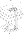
- FIG. 6 is an exploded perspective view of the beamforming antenna 1A according to the present embodiment.
- FIG. 7A is a plan view of an array antenna 22Ai that is one of a plurality of array antennas 22A provided in the beamforming antenna 1A.
- FIG. 7B is a plan view of the Rotman lens 32A provided in the beam forming antenna 1A.
- FIG. 7C is an enlarged view of an output port 322Ai that is one of the output ports 322A included in the Rotman lens 32A.
- members having the same functions as those described in the first embodiment are denoted by the same reference numerals, and the description thereof will not be repeated.
- each of the radiating elements 241i to 248i and 251i to 258i has a low angle dependency with respect to the oscillating direction. Therefore, in one embodiment of the present invention, it is desirable that the radiating elements be as straight as possible as described in Patent Document 2 and Patent Document 3.
- the beam forming antenna 1A is based on the configuration of the beam forming antenna 1 according to the first embodiment, and the radiating elements 241Ai to 248Ai and the radiating elements 251Ai to 258Ai are arranged in a straight line along the x axis.
- the radiating elements 241Ai to 248Ai and 251Ai to 258Ai are arranged on a straight line.
- Each of the plurality of array antennas 22A and the Rotman lens 32A of the beam forming antenna 1A is a member that replaces the plurality of array antennas 22 and the Rotman lens 32 of the beam forming antenna 1, respectively.
- the radiating elements 241Ai to 248Ai and 251Ai to 258Ai are configured as shown in FIG. Is configured as shown in FIG.
- the array antenna 22Ai is designed so that the radiating elements 241Ai to 248Ai and the radiating elements 251Ai to 258Ai are in the same straight line by bending the vicinity of the feeding point 23APi into a crank shape
- the Rotman lens 32A The plurality of output ports 322A of the Rotman lens 32 are arranged so that the end section including the tip of the output port 322A is along the direction (y-axis direction) in which the feed line 23ALi is extended in the vicinity of the feed point 23APi of the array antenna 22Ai.
- Each output port 322Ai is designed.
- the feed line 23ALi includes a feed section 231ALi, a first radiation section 232ALi, and a second radiation section 233ALi.
- the power feeding section 231ALi is located in the central portion of the power feeding line 23ALi and includes a power feeding portion 23APi.
- the power feeding section 231ALi extends along the y-axis direction (in the present embodiment, in parallel) that is the first direction described in the claims.
- the first radiation section 232ALi extends from one end portion (end portion on the y-axis negative direction side) of the power feeding section 231ALi along the x-axis positive direction (in parallel in the present embodiment).
- the x-axis positive direction corresponds to one of the second directions recited in the claims.
- the y-axis direction which is the first direction and the x-axis direction which is the second direction intersect (in the present embodiment, they are orthogonal).
- the second radiation section 233ALi extends from the other end (end on the y-axis positive direction side) of the power supply section 231ALi along the x-axis negative direction (in parallel in this embodiment).
- the x-axis negative direction corresponds to the other direction among the second directions described in the claims.
- Each of the radiating elements 241Ai to 248Ai is arranged on the y axis positive direction side of the first radiating section 232ALi, as shown in FIG.
- the configuration of the portion connecting each of the radiating elements 241Ai to 248Ai to the first radiating section 232ALi is that the radiating elements 241i to 248i with respect to the feed line 23Li provided in the beamforming antenna 1 according to the first embodiment. Is the same as the configuration of the portion (region R1) connecting each of these (see FIG. 3B).
- each of the radiating elements 251Ai to 258Ai is arranged on the y-axis negative direction side of the second radiating section 233ALi, as shown in FIG.
- the configuration of the portion connecting each of the radiating elements 251Ai to 258Ai to the second radiating section 233ALi is that the radiating elements 251i to 258i with respect to the feed line 23Li provided in the beam forming antenna 1 according to the first embodiment. This is the same as the configuration of the part connecting each of the above. (1) the length between the central axis of the first radiating section 232ALi and the center of each of the radiating elements 241Ai to 248Ai; (2) the central axis of the second radiating section 233ALi and the center of each of the radiating elements 251Ai to 258Ai; Are equal in length.
- each of the radiating elements 241Ai to 248Ai and 251Ai to 258Ai is disposed along a straight line passing along the x axis (in the present embodiment, parallel) and passing through the power feeding unit 23APi.
- the output port 322Ai that is each of the plurality of output ports 322A included in the Rotman lens 32A includes an end section 3221Ai and a center that is a section connected to the end section 3221Ai.
- Section 3222Ai is included.
- the end section 3221Ai includes the end of each output port 322Ai, and extends along the y-axis direction.
- the central section 3222Ai extends in the x-axis direction. That is, in the present embodiment, the end section 3221Ai and the center section 3222Ai are orthogonal to each other.
- each output port 322Ai only needs to be extended along the x-axis direction, which is the second direction, and the shape thereof is not limited.
- the shape may be a straight line or a meandering curve.
- each output port 322Ai (the end opposite to the end connected to the central section 3222Ai of the end section 3221Ai) is a slot that is any one of the slots constituting the slot 111. Via 111i, it couple
- the beamforming antenna 1 according to the first embodiment of the present invention includes the array antenna 22i shown in FIG.
- a beamforming antenna 1A according to the second embodiment of the present invention includes an array antenna 22Ai shown in FIG.
- the number of array antennas 22i and 22Ai included in the beamforming antennas 1 and 1A is six, and the number of power feeding ports 321i in each of the Rotman lenses 32 and 32A.
- the number of output ports 322i and 322Ai of the Rotman lenses 32 and 32A and the number of slots 111i are both six.
- the azimuth dependence (radiation pattern) of the gain obtained by the first embodiment is shown in FIG. 8A
- the azimuth dependence (radiation pattern) of the gain obtained by the second embodiment is shown in FIG. Shown in (b). Comparing the first and second embodiments with reference to FIGS. 8A and 8B, the radiation intensity decreases when the radiation direction is changed in the second embodiment. It can be confirmed that it is difficult. Note that the five plots shown in FIG. 8A were obtained by changing the power supply port 321i in each of the Rotman lenses 32 and 32A. The same applies to the five plots shown in FIG.
- An antenna device (1, 1A) includes a ground layer (11) made of a conductor, and a plurality of layers provided above the ground layer (11) and separated from the ground layer (11).
- Array antenna (22, 22A) and antenna device (1, 1A) including a Rotman lens (32, 32A) provided below the ground layer (11) and spaced from the ground layer (11)
- Each of the plurality of array antennas (22, 22A) (22i, 22Ai) includes a feed line (23Li, 23ALi) in which a feed point (23Pi, 23APi) is located in the center, and the feed line (23Li).
- the feeding points (23Pi, 23APi) are symmetrical with respect to the center of symmetry, and each of the feeding points (23Pi, 23APi) of the plurality of array antennas (22, 22A) is formed on the ground layer (11). It is characterized in that it is connected to the end of one of the output ports (322i, 322Ai) of the Rotman lens (32, 32A) through the slot (111) formed.
- this antenna device can realize an antenna device in which the peak direction of the radiation pattern does not depend on the frequency of the electromagnetic wave radiated.
- the effective wavelength in the feed line of the center frequency of the operation band of the antenna device (1, 1A) is defined as the center wavelength ⁇ , and the feed line (23Li, 23ALi).
- the branch section (27ji) is connected to the feeder line (23Li, 23ALi) Is formed by connecting a plurality of unit sections (271ji, 272ji, 273ji) having a length along the direction (x-axis direction) of ⁇ / 4, and the unit sections (271ji, 272ji, 273ji)
- the widths (W271ji, W272ji, W273ji) of each of the adjacent unit sections (271j It is preferable that the characteristic impedances Z1, Zb, and Zc of i, 272ji, 273ji) are determined so as to match.
- the gain of the antenna device can be increased.
- the branch section (27ji) includes a first section (271ji) and a second section that are continuous from the front stage to the rear stage of the feed line (23Li, 23ALi).
- Each of the radiating elements (241i to 248i, 251i to 258i, 241Ai to 248Ai, 251Ai to 258Ai) includes the first section (271ji) and the third section (272ji). 2 is connected in the vicinity of the boundary with the second section (272ji), and the width (W272ji) of the second section is a width at which the branching ratio in the branch section (27ji) becomes a predetermined value.
- the width of the section (W271ji) is a combined impedance of the second section (272ji) and the radiating element branched from the branch section (27ji).
- the width of the third section (273ji) (W273ji) is equal to the characteristic impedance of the second section (272ji) and the width of the branch section (272ji). It is preferable that the width be matched with the characteristic impedance of the latter stage of 27ji).
- the number of the plurality of radiating elements (241i to 248i, 251i to 258i, 241Ai to 248Ai, 251Ai to 258Ai) is four or more.
- the branch ratio of the branch section (27ji) to which each of the radiating elements (241i to 248i, 251i to 258i, 241Ai to 248Ai, 251Ai to 258Ai) is connected is provided in the preceding stage of the feed line (23Li, 23ALi) It is preferable that the branch section (27ji) is smaller and the branch section (27ji) provided in the subsequent stage of the feed line (23Li, 23ALi) is larger.
- the power of each beam radiated from each radiating element can be easily controlled, the radiation efficiency and the sidelobe ratio of the antenna device can be easily controlled. In other words, it is easy to design an antenna device having a desired radiation efficiency and sidelobe ratio.
- the feeding line (23ALi) includes (1) the feeding section including the feeding section (23APi) and extending along the first direction (y-axis direction). (231ALi) and (2) a second direction (x-axis direction) intersecting the first direction (y-axis direction) from one end (end on the negative y-axis side) of the power feeding section (231ALi) ) Of the first radiation section (232ALi) extended along one direction (x-axis positive direction), and (3) the other end (end on the y-axis positive direction side) of the feeding section (231ALi) Part) and a second radiation section (233ALi) extended along the other direction (x-axis negative direction) of the second direction (x-axis direction), and the first radiation section (232ALi) )
- An end section (3221Ai) including the end of any one of the output ports (322Ai) of the Rotman lens (32A) coupled to the power feeding section (23APi) is disposed on the first section (3221Ai).
- the section (3222Ai) extending along the first direction (y-axis direction) and continuing to the end section of the output port (322Ai) extends along the second direction (x-axis direction). It is preferable.
- the section connected to the end section of the output port only needs to be extended along the second direction, and the shape thereof is not limited.
- the shape may be a straight line or a meandering curve.
- the plurality of radiating elements (241i to 248i, 251i to 258i, 241Ai to 248Ai, 251Ai to 258Ai) are all congruent.
- the antenna device since the plurality of radiating elements are all congruent, the antenna device can be easily designed.
Landscapes
- Variable-Direction Aerials And Aerial Arrays (AREA)
- Aerials With Secondary Devices (AREA)
Abstract
放射パターンのピーク方向が放射する電磁波の周波数に依存しないアンテナ装置を実現すること。導電体からなるグランド層(11)と、グランド層(11)の上層に設けられた複数のアレイアンテナ(22)と、グランド層(11)の下層に設けられたロットマンレンズ(32)とを備えたアンテナ装置において、各アレイアンテナ(22i)は、その中央に給電点(23Pi)が位置する給電線路(23Li)と、給電線路(23Li)に接続された複数の放射素子(241i~248i,251i~258i)とを含み、且つ、給電点(23Pi)を対称の中心として点対称な形状であり、各給電点(23Pi)は、グランド層(11)に形成されたスロット(111i)を介してロットマンレンズ(32)の何れかの出力ポート(322i)と結合している。
Description
本発明は、高速伝送無線通信技術に関する。
近年通信容量拡大のため、より多くの情報を伝達できる広い帯域を持ったミリ波無線通信が注目を浴びている。しかしミリ波は損失が大きいため放射方向を絞り対象に向けて追従させるビームフォーミング技術が必要になる。通常ビームフォーミングを行う際、アンテナ素子毎にビーム数だけの位相素子が必要になる。しかし位相素子のコストが高いため、非特許文献1のように位相素子を使わずにビーム方向を制御するロットマンレンズを用いたものも研究されている。ロットマンレンズは非特許文献1にあるように平面パターンに、曲面と、給電するビームポート、放射素子につながるアレイポートからなる。ロットマンレンズは、給電するビームポートを変えることで各アレイポート間での時間遅延量が変化するため、広帯域にビームの放射方向を変化させることができる。
R. C. Hansen,' Design Tradesfor Rotman Lenses', IEEE TRANSACTIONS ON ANTENNAS AND PROPAGATION, VOL. 39, NO.4, APRIL 1991
Woosung Lee, et al, ' CompactTwo-Layer Rotman Lens-Fed Microstrip Antenna Array at 24 GHz', IEEETRANSACTIONS ON ANTENNAS AND PROPAGATION, VOL. 59, NO. 2, FEBRUARY 2011
非特許文献2のように給電線路の一方の端部に給電点が位置する直列給電アレイアンテナをロットマンレンズに対して接続する場合、直列給電アレイアンテナから放射する電磁波の周波数に依存して、放射される放射パターンのピーク方向が変化してしまうという問題があった。
本発明は、上記の課題に鑑みてなされたものであり、その目的は、ロットマンレンズを備えたアンテナ装置であって、放射パターンのピーク方向が放射する電磁波の周波数に依存しないアンテナ装置を実現することを目的とする。
上記の課題を解決するために、本発明の一態様に係るアンテナ装置は、導電体からなるグランド層と、当該グランド層の上層に当該グランド層と離間して設けられた複数のアレイアンテナと、当該グランド層の下層に当該グランド層と離間して設けられたロットマンレンズとを備えたアンテナ装置であって、前記複数のアレイアンテナの各々は、その中央に給電点が位置する給電線路と、当該給電線路に接続された複数の放射素子とを含み、且つ、前記給電点を対称の中心として点対称な形状であり、前記複数のアレイアンテナの給電点の各々は、前記グランド層に形成されたスロットを介して前記ロットマンレンズの何れかの出力ポートの端部と結合している、ことを特徴とする。
本発明の一態様に係るアンテナ装置は、ロットマンレンズを備えたアンテナ装置であって、放射パターンのピーク方向が放射する電磁波の周波数に依存しないアンテナ装置を実現することができる。
〔ビームフォーミングアンテナの概要〕
本発明の一実施形態に係るビームフォーミングアンテナ(請求の範囲に記載のアンテナ装置に対応)の概要について、図1を参照して説明する。
本発明の一実施形態に係るビームフォーミングアンテナ(請求の範囲に記載のアンテナ装置に対応)の概要について、図1を参照して説明する。
図1に示すように、本発明の一実施形態に係るビームフォーミングアンテナは、グランド層と複数のアレイアンテナと、ロットマンレンズとを備えている。
グランド層は、導電体からなる膜又は板により構成されている。複数のアレイアンテナは、グランド層の上層にグランド層と離間して設けられている。ロットマンレンズは、グランド層の下層にグランド層と離間して設けられている。図1においては、斜視図を見やすくするためにグランド層を仮想線(二点鎖線)にて示している。また、同様の理由から、グランド層の設けられた複数のスロットの図示を省略している。なお、複数のスロットの詳細については、図2及び図3の(a)、並びに、図6及び図7の(a)を参照して後述する。各スロットは、ビームフォーミングアンテナを平面視した場合に、ロットマンレンズの出力ポートの端部とアレイアンテナの給電点とが重畳する領域に設けられている。
複数のアレイアンテナの各々は、その中央に給電点が位置する給電線路と、当該給電線路に接続された複数の放射素子とを含み、且つ、給電点を対称の中心として点対称な形状である(図3の(a)及び図7の(a)参照)。
複数のアレイアンテナの給電点の各々は、グランド層に形成されたスロットを介してロットマンレンズの何れかの出力ポートの端部と結合している(図2、図3の(a)、図6、及び図7の(a)参照)。
なお、このようなビームフォーミングアンテナは、例えば、グランド層と、グランド層を挟持する2つの誘電体層(第1の誘電体層及び第2の誘電体層)とにより構成された誘電体基板を用いて実現することができる。この場合、複数のアレイアンテナを誘電体基板のおもて面に形成し、ロットマンレンズを誘電体基板のうら面に形成すればよい。
この構成によれば、複数のアレイアンテナとロットマンレンズとを同一基板上に形成することができるため、ビームフォーミングアンテナの製造コストを抑制することができる。
〔第1の実施形態〕
以下、本発明の第1の実施形態に係るビームフォーミングアンテナについて、図2~図5を参照して説明する。図2は、本実施形態に係るビームフォーミングアンテナ1の分解斜視図である。図3の(a)は、ビームフォーミングアンテナ1が備えている複数のアレイアンテナ22の1つであるアレイアンテナ22iの平面図である。図3の(b)は、図3の(a)に示したアレイアンテナ22iの拡大平面図であり、図3の(a)に示した領域R1の拡大平面図である。図4は、図3に示したアレイアンテナ22iの分岐部分の平面図である。図5は、ビームフォーミングアンテナ1が備えているロットマンレンズ32の平面図である。また、非特許文献2に記載の直列給電アレイアンテナ(以下、従来のビームフォーミングアンテナ101)の分解斜視図を図9に示す。
以下、本発明の第1の実施形態に係るビームフォーミングアンテナについて、図2~図5を参照して説明する。図2は、本実施形態に係るビームフォーミングアンテナ1の分解斜視図である。図3の(a)は、ビームフォーミングアンテナ1が備えている複数のアレイアンテナ22の1つであるアレイアンテナ22iの平面図である。図3の(b)は、図3の(a)に示したアレイアンテナ22iの拡大平面図であり、図3の(a)に示した領域R1の拡大平面図である。図4は、図3に示したアレイアンテナ22iの分岐部分の平面図である。図5は、ビームフォーミングアンテナ1が備えているロットマンレンズ32の平面図である。また、非特許文献2に記載の直列給電アレイアンテナ(以下、従来のビームフォーミングアンテナ101)の分解斜視図を図9に示す。
従来のビームフォーミングアンテナ101は、図9に示すように、グランド層141と、誘電体層121と、複数のアレイアンテナ122と、誘電体層131と、ロットマンレンズ132とを備えている。ロットマンレンズ132は、複数の給電ポート1321と、複数の出力ポート1322と、本体1323とを備えている。グランド層141には、複数のスロット1141が設けられている。ロットマンレンズ132の複数の出力ポート1322の各々の一方の端部(本体1323と逆側の端部)と、複数のアレイアンテナ122の一方の端部である給電点とは、複数のスロット1141を介して結合している。なお、図9の二点鎖線は、複数のアレイアンテナ122が形成されている面と、ロットマンレンズ132が形成されている面を仮想的に示している。図9において、複数のアレイアンテナ122と誘電体層121の一方の主面とは、互いに離間しているように描かれている。しかし、実際には、複数のアレイアンテナ122は、誘電体層121の一方の主面に積層されている。ロットマンレンズ132についても同様である。
一方、請求の範囲に記載のアンテナ装置の一態様であるビームフォーミングアンテナ1は、図2に示すように、グランド層11と、誘電体層21と、複数のアレイアンテナ22と、誘電体層31と、ロットマンレンズ32とを備えている。
図2に図示した座標系は、誘電体層21の主面211の法線に沿う方向をz軸方向と定め、後述する各アレイアンテナ22iの給電線路23Li(図3参照)が延伸されている方向をx軸方向と定め、x軸方向及びz軸方向とともに右手系の直交座標系を構成するようにy軸方向を定めている。また、z軸方向において主面212から主面211へ向かう方向をz軸正方向と定め、後述するロットマンレンズ32の複数の出力ポート322から複数の給電ポート321へ向かう方向をx軸正方向と定め、x軸正方向及びz軸正方向とともに右手系の直交座標系を構成するようにy軸正方向を定めている。
グランド層11と、グランド層11を挟持する一対の誘電体層である誘電体層21,31とは、誘電体基板を構成する。誘電体層21の一方の主面(z軸正方向側の主面)である主面211は、誘電体基板のおもて面を構成し、誘電体層21の他方の主面(z軸負方向側の主面)である主面212は、グランド層11と接触している。誘電体層31の一方の主面(z軸正方向側の主面)である主面311は、グランド層11と接触しており、誘電体層31の他方の主面(z軸負方向側の主面)である主面312は、誘電体基板のうら面を構成する。
(複数のアレイアンテナ22)
複数のアレイアンテナ22は、主面211に積層された導体膜(本実施形態では銅製の薄膜)をパターニングすることによって得られる導体パターンである。本実施形態において、10個のアレイアンテナ22iにより構成されており、各アレイアンテナ22iの形状は、図3の(a)及び(b)に示す通りである。
複数のアレイアンテナ22は、主面211に積層された導体膜(本実施形態では銅製の薄膜)をパターニングすることによって得られる導体パターンである。本実施形態において、10個のアレイアンテナ22iにより構成されており、各アレイアンテナ22iの形状は、図3の(a)及び(b)に示す通りである。
各アレイアンテナ22iは、給電線路23Liと、給電線路23Liに接続された16個の放射素子241i~248i,251i~258iと、給電線路23Liと放射素子241i~248iの各々とを接続するサブ給電線路261i~268iと、給電線路23Liと放射素子251i~258iの各々とを接続するサブ給電線路線とを備えている。給電線路23Liは、x軸方向に沿って延伸された帯状の導体パターンである。給電線路23Liの中央には、給電点23Piが位置する。
本実施形態では、図3の(b)に示すように、給電線路23Liのうち給電点23Piからx軸正方向側に延伸された部分と、当該部分に接続されたサブ給電線路261i~268iと、放射素子241i~248iとを用いて各アレイアンテナ22iの構成を説明する。各アレイアンテナ22iは、図3の(a)に示すように、給電点23Piを対称の中心として点対称な形状を有する。したがって、本実施形態では、給電線路23Liのうち給電点23Piからx軸負方向側に延伸された部分と、当該部分に接続された8本のサブ給電線路と、放射素子251i~258iとに関する説明を省略する。
給電線路23Liのうち給電点23Piからx軸正方向側に延伸された部分は、サブ給電線路261i~267iの各々が接続される分岐区間271i~277iを含んでいる。分岐区間271iは、給電点23Piに最も近い分岐区間、すなわち、最前段の分岐区間であり、分岐区間277iは、給電点23Piから最も遠い分岐区間、すなわち、最後段の分岐区間であり、分岐区間271iと分岐区間277iとの間には、給電点23Piに近い側から遠い側に向かって、すなわち、前段から後段に向かって分岐区間272i~276iが等間隔で配置されている。また、給電線路23Liのうち給電点23Piからx軸正方向側に延伸された部分の末端である末端部278iには、サブ給電線路268iが接続される。なお、分岐区間271i~277iのことを分岐区間27ji(jは、1≦j≦7の整数)と一般化して表す。
ビームフォーミングアンテナ1において、動作帯域の中心周波数の前記給電線路における実効波長を中心波長λとして、分岐区間27jiの各々は、x軸方向に沿った長さがλ/4である単位区間271ji,272ji,273jiを連ねることにより構成されている。単位区間271ji,272ji,273jiの各々は、給電線路23Liの前段から後段に向かって連なる単位区間であり、それぞれ、請求の範囲に記載の第1の区間、第2の区間、及び第3の区間に対応する。以下において、単位区間271ji,272ji,273jiの各々のことを第1の区間271ji、第2の区間272ji、及び第3の区間273jiとも呼ぶ。第1~第3の区間271ji,272ji,273jiの各々の幅W271ji,W272ji,W273jiは、それぞれ、隣接する第1~第3の区間271ji,272ji,273jiの特性インピーダンスZ1,Zb,Zcが整合するように定められている。
この構成によれば、給電線路23Liに対して各放射素子241i~247iが接続されることにより生じ得る反射損失を抑制することができる。したがって、ビームフォーミングアンテナ1の利得を高めることができる。
また、各放射素子241i~247iの各々は、第1の区間271jiと第2の区間272jiとの境界近傍に、サブ給電線路261i~267iの各々を介して接続されている。サブ給電線路261i~267iの各々は、第1の区間271jiと第2の区間272jiとの境界近傍からy軸正方向に向かって延伸されている。なお、サブ給電線路268iは、サブ給電線路261i~267iの各々と同一に構成されている。
給電線路23Liにおいて、給電点23Piに供給された電流は、給電点23Piから末端部278iに向かう過程において、分岐区間271i~277iの各々を順番に通過する。上記電流が分岐区間271i~277iの各々、例えば分岐区間271iを通過するとき、給電線路23Liを流れる電流は、そのまま給電線路23Liを次の分岐区間である分岐区間272iに向かって流れる電流と、サブ給電線路261iを放射素子241iに向かって流れる電流とに分けられる。給電線路23Liを分岐区間272iに向かって流れる電流を第1の電流とし、サブ給電線路261iを放射素子241iに向かって流れる電流を第2の電流とする。分岐区間271iにおける分岐比、すなわち、分岐区間272iに給電される電力に対する放射素子241iに給電される電力の比は、第1の電流に対する第2の電流の比により与えられる。他の分岐区間272i~277iにおける分岐比も同様である。
ここで、幅W272jiは、分岐区間27jiにおける分岐比が所定の値になる幅であり、幅W271jiは、第2の区間272jiと分岐区間27jiから分岐される放射素子との合成インピーダンスと、分岐区間27jiの前段の特性インピーダンスとを整合させる幅であり、第3の区間273jiの幅W273jiは、第2の区間272jiの特性インピーダンスと、分岐区間27jiの後段の特性インピーダンスとを整合させる幅である。
この構成によれば、給電線路に対して各放射素子が接続されることにより生じ得る反射損失を確実に抑制することができる。したがって、アンテナ装置の利得を確実に高めることができる。
また、分岐区間27jiの各々の分岐比は、給電線路23Liの前段に設けられた分岐区間27jiほど小さく、給電線路23Liの後段に設けられた分岐区間27jiほど大きくなるように定められている。すなわち、分岐区間271iの分岐比が最も小さく、分岐区間272i~276iの分岐比がこの順番で大きくなり、分岐区間277iの分岐比が最も大きくなるように定められている。
この構成によれば、各放射素子241i~248iから放射される各ビームのパワーを容易に制御することができるため、ビームフォーミングアンテナ1の放射効率やサイドローブ比を容易に制御することができる。換言すれば、所望の放射効率やサイドローブ比を有するビームフォーミングアンテナ1の設計が容易になる。
また、アレイアンテナ22iにおいて、放射素子241i~248i,251i~258iの各々は、何れも合同である。この構成によれば、複数の放射素子が何れも合同であることによって、ビームフォーミングアンテナ1の設計が容易になる。
(ロットマンレンズ32)
ロットマンレンズ32は、主面312に積層された導体膜(本実施形態では銅製の薄膜)をパターニングすることによって得られる導体パターンである。図5に示すように、ロットマンレンズ32は、複数の給電ポート321と、複数の出力ポート322と、本体323とを備えている。本実施形態において、複数の給電ポート321は、9個の給電ポート321iにより構成されており、複数の出力ポート3222は、10個の出力ポート322iにより構成されている。
ロットマンレンズ32は、主面312に積層された導体膜(本実施形態では銅製の薄膜)をパターニングすることによって得られる導体パターンである。図5に示すように、ロットマンレンズ32は、複数の給電ポート321と、複数の出力ポート322と、本体323とを備えている。本実施形態において、複数の給電ポート321は、9個の給電ポート321iにより構成されており、複数の出力ポート3222は、10個の出力ポート322iにより構成されている。
各出力ポート322iの端部のうち本体323と逆側の端部(各出力ポート322iの末端部)を含む端部区間は、何れもx軸に沿って延伸されている。
図5に示すようにロットマンレンズ32を平面視した場合に、グランド層11のうち、各出力ポート322iの末端部近傍に対応する位置には、それぞれ、スロット111iが設けられている。すなわち、グランド層11には、複数のスロット111が設けられている。
(複数のアレイアンテナ22及びロットマンレンズ32の結合)
図3の(a)に示すように、アレイアンテナ22iを平面視した場合に、給電点23Piがロットマンレンズ32の出力ポート322iの末端部及びグランド層11のスロット111iに重畳するように、複数のアレイアンテナ22は、主面211に配置されている。したがって、複数のアレイアンテナ22の給電点23Piの各々は、スロット111iを介して、ロットマンレンズ32の何れかの出力ポート322iの末端部と結合している。したがって、ロットマンレンズ32の何れかの給電ポート321iに供給され、本体323を経て、各出力ポート322iの末端部に至った電力は、スロット111iを介して各アレイアンテナ22iの給電点23Piと結合し、各アレイアンテナ22iの放射素子241i~248i,251i~258iから放射される。
図3の(a)に示すように、アレイアンテナ22iを平面視した場合に、給電点23Piがロットマンレンズ32の出力ポート322iの末端部及びグランド層11のスロット111iに重畳するように、複数のアレイアンテナ22は、主面211に配置されている。したがって、複数のアレイアンテナ22の給電点23Piの各々は、スロット111iを介して、ロットマンレンズ32の何れかの出力ポート322iの末端部と結合している。したがって、ロットマンレンズ32の何れかの給電ポート321iに供給され、本体323を経て、各出力ポート322iの末端部に至った電力は、スロット111iを介して各アレイアンテナ22iの給電点23Piと結合し、各アレイアンテナ22iの放射素子241i~248i,251i~258iから放射される。
(ビームフォーミングアンテナ1の機能)
従来のビームフォーミングアンテナにおいて放射パターンのピーク方向と、天頂方向とのなす角をθとした場合、

と表すことができる。ただし天頂方向を0°とし、天頂方向を向くときの周波数をf0、そこからの周波数のずれをΔfとする。
従来のビームフォーミングアンテナにおいて放射パターンのピーク方向と、天頂方向とのなす角をθとした場合、
しかし、図3の(a)のように給電線路23Liの中央(本実施形態においては中点)に給電点23Piを配置することでピークがずれる向きが反対のビームが重ねあわされるため、ピークが変化しにくくなる。本発明の一態様であるビームフォーミングアンテナ1は、それを利用したものである。
また、アレイアンテナの放射効率やサイドローブ比は、放射素子の給電強度比に依存する。そのため特許文献1のように給電比を調整するために放射素子自体の大きさを変えることがある。しかし、そうすると各放射素子の整合、給電比の調整が難しくなる。本発明の一実施形態に係るビームフォーミングアンテナ1は、図3の(b)のように給電線路23Liから放射素子241i~247iへ電力を分岐する分岐区間27jiの構成と、放射素子241i~247iの大きさとをすべての放射素子241i~247iで一定にし、且つ、給電線路23Liの幅を単位区間(第1~第3の区間271ji,272ji,273ji)毎に変えることで各放射素子241i~248iへの分配比を調整している。これらの構成を用いて放射パターンを制御することで、ビームフォーミングアンテナ1は、その設計を簡単にしている。
図4にあるように、給電線23Liから各放射素子241i~247iへの各分岐比は、特性インピーダンスZaとZbの比で決まる。合成インピーダンスZab=Za・Zb/ ( Za+Zb )であらわされ、整合をとるために

で表される。同様に

と求めることができ、給電線路23Liの特性インピーダンスであるZ0と分岐比、Zaを初期値として決めることで、図4に示す給電線路23Liに含まれる分岐区間27jiを構成する第1~第3の区間271ji,272ji,273jiの幅W271ji,W272ji,W273jiをそれぞれ求めることができ、所望の分岐比を簡単に得ることができる。したがって、ビームフォーミングアンテナ1は、インピーダンス整合を取りつつ設計することができる。その結果、ビームフォーミングアンテナ1は、インピーダンス整合をとることができるため、分岐区間27jiにおいて生じ得る反射損失を抑制することができる。
〔第2の実施形態〕
以下、本発明の第2の実施形態に係るビームフォーミングアンテナについて、図6~図7を参照して説明する。図6は、本実施形態に係るビームフォーミングアンテナ1Aの分解斜視図である。図7の(a)は、ビームフォーミングアンテナ1Aが備えている複数のアレイアンテナ22Aの1つであるアレイアンテナ22Aiの平面図である。図7の(b)は、ビームフォーミングアンテナ1Aが備えているロットマンレンズ32Aの平面図である。図7の(c)は、ロットマンレンズ32Aが備えている出力ポート322Aの1つである出力ポート322Aiを拡大した拡大図である。なお、説明の便宜上、第1の実施形態にて説明した部材と同じ機能を有する部材については、同じ符号を付記し、その説明を繰り返さない。
以下、本発明の第2の実施形態に係るビームフォーミングアンテナについて、図6~図7を参照して説明する。図6は、本実施形態に係るビームフォーミングアンテナ1Aの分解斜視図である。図7の(a)は、ビームフォーミングアンテナ1Aが備えている複数のアレイアンテナ22Aの1つであるアレイアンテナ22Aiの平面図である。図7の(b)は、ビームフォーミングアンテナ1Aが備えているロットマンレンズ32Aの平面図である。図7の(c)は、ロットマンレンズ32Aが備えている出力ポート322Aの1つである出力ポート322Aiを拡大した拡大図である。なお、説明の便宜上、第1の実施形態にて説明した部材と同じ機能を有する部材については、同じ符号を付記し、その説明を繰り返さない。
ロットマンレンズ32を使い、複数のアレイアンテナ22の放射方向を振る場合、各放射素子241i~248i,251i~258iは、振る方向に対して角度依存性が低いほうが望ましい。そのため、本発明の一実施形態において、放射素子は、特許文献2及び特許文献3に記載されているようになるべく一直線上にあることが望ましい。ビームフォーミングアンテナ1Aは、第1の実施形態に係るビームフォーミングアンテナ1の構成をベースにし、放射素子241Ai~248Aiと放射素子251Ai~258Aiとがx軸に沿って一直線状に配置されるように、放射素子241Ai~248Ai,251Ai~258Aiの配置を変更することによって得られる。すなわち、ビームフォーミングアンテナ1Aが備えているアレイアンテナ22Ai(図7の(a)参照)において、複数の放射素子241Ai~248Ai,251Ai~258Aiは、一直線上に配置されている。
なお、ビームフォーミングアンテナ1Aの複数のアレイアンテナ22A及びロットマンレンズ32Aの各々は、それぞれ、ビームフォーミングアンテナ1の複数のアレイアンテナ22及びロットマンレンズ32にとって代わる部材である。
グランド層11に設けられた複数のスロット11のうちの1つであるスロット111iを介して給電線路23ALiの中央に位置する給電点23APiへ中央給電する場合、給電点23APiから放射素子241Ai~248Aiへ向かうかう方向、及び、給電点23APiから放射素子251Ai~258Aiへ向かうかう方向の各方向へは、電流が逆位相で給電される。そのためパッチアンテナ(放射素子)への給電は、放射素子241Ai~248Ai及び放射素子251Ai~258Aiの各々に対して逆方向から行う必要がある。
逆方向から給電しつつ同一直線状に放射素子を配置するため、ビームフォーミングアンテナ1Aにおいては、放射素子241Ai~248Ai,251Ai~258Aiを図7の(a)に示すように構成し、ロットマンレンズ32Aを図7の(b)に示すように構成する。すなわち、(1)給電点23APi付近をクランク状に折り曲げて放射素子241Ai~248Aiと、放射素子251Ai~258Aiとが同一直線状になるようにアレイアンテナ22Aiを設計し、(2)ロットマンレンズ32Aの出力ポート322Aの先端部を含む端部区間がアレイアンテナ22Aiの給電点23APi付近における給電線路23ALiが延伸されている方向(y軸方向)に沿うように、ロットマンレンズ32の複数の出力ポート322Aの各々である出力ポート322Aiを設計する。
より具体的には、図7の(a)に示すように、給電線路23ALiは、給電区間231ALiと、第1の放射区間232ALiと、第2の放射区間233ALiとにより構成されている。給電区間231ALiは、給電線路23ALiの中央部分に位置し、給電部23APiを含む。給電区間231ALiは、請求の範囲に記載の第1の方向であるy軸方向に沿って(本実施形態では平行に)延伸されている。第1の放射区間232ALiは、給電区間231ALiの一方の端部(y軸負方向側の端部)からx軸正方向に沿って(本実施形態では平行に)延伸されている。x軸正方向は、請求の範囲に記載の第2の方向のうち一方の方向に対応する。当然のことながら、第1の方向であるy軸方向と第2の方向であるx軸方向とは、交わっている(本実施形態では直交している)。第2の放射区間233ALiは、給電区間231ALiの他方の端部(y軸正方向側の端部)からx軸負方向に沿って(本実施形態では平行に)延伸されている。x軸負方向は、請求の範囲に記載の第2の方向のうち他方の方向に対応する。
放射素子241Ai~248Aiの各々は、図7の(a)に示すように、第1の放射区間232ALiのy軸正方向側に配置されている。第1の放射区間232ALiに対して放射素子241Ai~248Aiの各々を接続する部分の構成は、第1の実施形態に係るビームフォーミングアンテナ1が備えている給電線路23Liに対して放射素子241i~248iの各々を接続する部分(領域R1)の構成と同じである(図3の(b)参照)。また、放射素子251Ai~258Aiの各々は、図7の(a)に示すように、第2の放射区間233ALiのy軸負方向側に配置されている。第2の放射区間233ALiに対して放射素子251Ai~258Aiの各々を接続する部分の構成は、第1の実施形態に係るビームフォーミングアンテナ1が備えている給電線路23Liに対して放射素子251i~258iの各々を接続する部分の構成と同じである。(1)第1の放射区間232ALiの中心軸と放射素子241Ai~248Aiの各々の中心との長さと、(2)第2の放射区間233ALiの中心軸と放射素子251Ai~258Aiの各々の中心との長さは、何れも等しい。また、給電区間231ALiにおいて、給電部23APiから給電区間231ALiの一方の端部(y軸負方向側の端部)までの長さと、給電部23APiから給電区間231ALiの他方の端部(y軸正方向側の端部)までの長さは等しい。したがって、放射素子241Ai~248Ai,251Ai~258Aiの各々は、x軸に沿い(本実施形態では平行であり)、且つ、給電部23APiを通る直線上に配置されている。
また、図7の(c)に示すように、ロットマンレンズ32Aが備えている複数の出力ポート322Aの各々である出力ポート322Aiは、端部区間3221Aiと、端部区間3221Aiに連なる区間である中央区間3222Aiとを含んでいる。端部区間3221Aiは、各出力ポート322Aiの端部を含み、且つ、y軸方向に沿って延伸されている。中央区間3222Aiは、x軸方向に延伸されている。すなわち、本実施形態において、端部区間3221Aiと中央区間3222Aiとは、直交している。
この構成によれば、複数の放射素子241Ai~248Ai,251Ai~258Aiが同一直線上に配置されていることによって、広帯域かつ広角のビーム走査を可能にする。なお、各出力ポート322Aiの中央区間3222Aiは、第2の方向であるx軸方向に沿って延伸されていればよく、その形状は限定されるものではない。例えば、その形状は、直線であってもよいし、蛇行した曲線であってもよい。
なお、各出力ポート322Aiの端部(端部区間3221Aiの中央区間3222Aiに連なる側の端部と逆側の端部)は、スロット111を構成するスロットのうちの何れか1つのスロットであるスロット111iを介して、複数のアンテナアレイ22Aを構成するアンテナアレイのうち何れか1つのアンテナアレイであるアンテナアレイ22Aiの給電点23APiと結合している。
〔実施例〕
本発明の第1の実施例であるビームフォーミングアンテナ1は、図3に示したアレイアンテナ22iを備えている。本発明の第2の実施例であるビームフォーミングアンテナ1Aは、図7の(a)に示したアレイアンテナ22Aiを備えている。なお、第1の実施例及び第2の実施例では、ビームフォーミングアンテナ1,1Aが備えているアレイアンテナ22i,22Aiの数を6個とし、ロットマンレンズ32,32Aの各々における給電ポート321iの数は5個とし、ロットマンレンズ32,32Aの出力ポート322i,322Aiの数、及び、スロット111iの数は、何れも6個とした。
本発明の第1の実施例であるビームフォーミングアンテナ1は、図3に示したアレイアンテナ22iを備えている。本発明の第2の実施例であるビームフォーミングアンテナ1Aは、図7の(a)に示したアレイアンテナ22Aiを備えている。なお、第1の実施例及び第2の実施例では、ビームフォーミングアンテナ1,1Aが備えているアレイアンテナ22i,22Aiの数を6個とし、ロットマンレンズ32,32Aの各々における給電ポート321iの数は5個とし、ロットマンレンズ32,32Aの出力ポート322i,322Aiの数、及び、スロット111iの数は、何れも6個とした。
第1の実施例により得られた利得の方位依存性(放射パターン)を図8の(a)に示し、第2の実施例により得られた利得の方位依存性(放射パターン)を図8の(b)に示す。図8の(a)及び(b)を参照して第1の実施例と第2の実施例とを比較すると、第2の実施例の方が放射方向を変化させた時、放射強度が落ちにくくなっていることが確認できる。なお、図8の(a)に示した5つのプロットは、それぞれ、ロットマンレンズ32,32Aの各々における給電ポート321iを変更することにより得た。図5の(b)に示した5つのプロットについても同様である。
(まとめ)
本発明の一態様に係るアンテナ装置(1,1A)は、導電体からなるグランド層(11)と、当該グランド層(11)の上層に当該グランド層(11)と離間して設けられた複数のアレイアンテナ(22,22A)と、当該グランド層(11)の下層に当該グランド層(11)と離間して設けられたロットマンレンズ(32,32A)とを備えたアンテナ装置(1,1A)であって、前記複数のアレイアンテナ(22,22A)の各々(22i,22Ai)は、その中央に給電点(23Pi,23APi)が位置する給電線路(23Li,23ALi)と、当該給電線路(23Li,23ALi)に接続された複数の放射素子(241i~248i,251i~258i,241Ai~248Ai,251Ai~258Ai)とを含み、且つ、前記給電点(23Pi,23APi)を対称の中心として点対称な形状であり、前記複数のアレイアンテナ(22,22A)の給電点(23Pi,23APi)の各々は、前記グランド層(11)に形成されたスロット(111)を介して前記ロットマンレンズ(32,32A)の何れかの出力ポート(322i,322Ai)の端部と結合している、ことを特徴とする。
本発明の一態様に係るアンテナ装置(1,1A)は、導電体からなるグランド層(11)と、当該グランド層(11)の上層に当該グランド層(11)と離間して設けられた複数のアレイアンテナ(22,22A)と、当該グランド層(11)の下層に当該グランド層(11)と離間して設けられたロットマンレンズ(32,32A)とを備えたアンテナ装置(1,1A)であって、前記複数のアレイアンテナ(22,22A)の各々(22i,22Ai)は、その中央に給電点(23Pi,23APi)が位置する給電線路(23Li,23ALi)と、当該給電線路(23Li,23ALi)に接続された複数の放射素子(241i~248i,251i~258i,241Ai~248Ai,251Ai~258Ai)とを含み、且つ、前記給電点(23Pi,23APi)を対称の中心として点対称な形状であり、前記複数のアレイアンテナ(22,22A)の給電点(23Pi,23APi)の各々は、前記グランド層(11)に形成されたスロット(111)を介して前記ロットマンレンズ(32,32A)の何れかの出力ポート(322i,322Ai)の端部と結合している、ことを特徴とする。
上記の構成によれば、アレイアンテナに対する給電を給電線路の中央から行うため、給電する電磁波の周波数を変化させた場合であっても、この周波数の変化にともなうビーム方向の変化を抑制することができる。したがって、本アンテナ装置は、放射パターンのピーク方向が放射する電磁波の周波数に依存しないアンテナ装置を実現することができる。
本発明の一態様に係るアンテナ装置(1,1A)において、当該アンテナ装置(1,1A)の動作帯域の中心周波数の前記給電線路における実効波長を中心波長λとして、前記給電線路(23Li,23ALi)に対して前記複数の放射素子(241i~248i,251i~258i,241Ai~248Ai,251Ai~258Ai)の各々が接続される区間である分岐区間(27ji)は、前記給電線路(23Li,23ALi)が延伸されている方向(x軸方向)に沿った長さがλ/4である単位区間(271ji,272ji,273ji)を複数個連ねることにより構成され、前記単位区間(271ji,272ji,273ji)の各々の幅(W271ji,W272ji,W273ji)は、隣接する単位区間(271ji,272ji,273ji)の特性インピーダンスZ1,Zb,Zcが整合するように定められている、ことが好ましい。
上記の構成によれば、給電線路に対して各放射素子が接続されることにより生じ得る反射損失を抑制することができる。したがって、アンテナ装置の利得を高めることができる。
本発明の一態様に係るアンテナ装置(1,1A)において、前記分岐区間(27ji)は、前記給電線路(23Li,23ALi)の前段から後段に向かって連なる第1の区間(271ji)、第2の区間(272ji)、及び第3の区間(273ji)を含み、各放射素子(241i~248i,251i~258i,241Ai~248Ai,251Ai~258Ai)は、前記第1の区間(271ji)と前記第2の区間(272ji)との境界近傍に接続されており、前記第2の区間の幅(W272ji)は、当該分岐区間(27ji)における分岐比が所定の値になる幅であり、前記第1の区間の幅(W271ji)は、前記第2の区間(272ji)と前記分岐区間(27ji)から分岐される放射素子との合成インピーダンスと、前記分岐区間の前段の特性インピーダンスとを整合させる幅であり、前記第3の区間(273ji)の幅(W273ji)は、前記第2の区間(272ji)の特性インピーダンスと、前記分岐区間(27ji)の後段の特性インピーダンスとを整合させる幅である、ことが好ましい。
上記の構成によれば、給電線路に対して各放射素子が接続されることにより生じ得る反射損失を確実に抑制することができる。したがって、アンテナ装置の利得を確実に高めることができる。
本発明の一態様に係るアンテナ装置(1,1A)において、前記複数の放射素子(241i~248i,251i~258i,241Ai~248Ai,251Ai~258Ai)の数は、4つ以上であり、前記複数の放射素子(241i~248i,251i~258i,241Ai~248Ai,251Ai~258Ai)の各々が接続される分岐区間(27ji)の分岐比は、前記給電線路(23Li,23ALi)の前段に設けられた分岐区間(27ji)ほど小さく、前記給電線路(23Li,23ALi)の後段に設けられた分岐区間(27ji)ほど大きい、ことが好ましい。
上記の構成によれば、各放射素子から放射される各ビームのパワーを容易に制御することができるため、アンテナ装置の放射効率やサイドローブ比を容易に制御することができる。換言すれば、所望の放射効率やサイドローブ比を有するアンテナ装置の設計が容易になる。
本発明の一態様に係るアンテナ装置(1A)において、前記給電線路(23ALi)は、(1)前記給電部(23APi)を含み第1の方向(y軸方向)に沿って延伸された給電区間(231ALi)と、(2)当該給電区間(231ALi)の一方の端部(y軸負方向側の端部)から前記第1の方向(y軸方向)に交わる第2の方向(x軸方向)のうち一方の方向(x軸正方向)に沿って延伸された第1の放射区間(232ALi)と、(3)当該給電区間(231ALi)の他方の端部(y軸正方向側の端部)から前記第2の方向(x軸方向)のうち他方の方向(x軸負方向)に沿って延伸された第2の放射区間(233ALi)とを含み、前記第1の放射区間(232ALi)に接続された1又は複数の放射素子(241Ai~248Ai)、及び、前記第2の放射区間(233ALi)に接続された1又は複数の放射素子(251Ai~258Ai)は、同一直線(x軸に沿った直線であって給電部23APiを通る直線)上に配置されており、前記給電部(23APi)に対して結合する前記ロットマンレンズ(32A)の前記いずれかの出力ポート(322Ai)の前記端部を含む端部区間(3221Ai)は、前記第1の方向(y軸方向)に沿って延伸されており、当該出力ポート(322Ai)の前記端部区間に連なる区間(3222Ai)は、前記第2の方向(x軸方向)に沿って延伸されている、ことが好ましい。
上記の構成によれば、複数の放射素子が同一直線上に配置されていることによって、広帯域かつ広角のビーム走査を可能にする。なお、出力ポートの前記端部区間に連なる区間は、第2の方向に沿って延伸されていればよく、その形状は限定されるものではない。例えば、その形状は、直線であってもよいし、蛇行した曲線であってもよい。
本発明の一態様に係るアンテナ装置(1,1A)において、前記複数の放射素子(241i~248i,251i~258i,241Ai~248Ai,251Ai~258Ai)は、何れも合同である、ことが好ましい。
上記の構成によれば、複数の放射素子が何れも合同であることによって、アンテナ装置の設計が容易になる。
本発明は上述した各実施形態に限定されるものではなく、請求項に示した範囲で種々の変更が可能であり、異なる実施形態にそれぞれ開示された技術的手段を適宜組み合わせて得られる実施形態についても本発明の技術的範囲に含まれる。
1,1A ビームフォーミングアンテナ(アンテナ装置)
11 グランド層
111 複数のスロット
111i スロット
21 誘電体層
22,22A 複数のアンテナアレイ
22i,22Ai アンテナアレイ
23Li,23ALi 給電線路
23Pi,23APi 給電点
231ALi 給電区間
232ALi 第1の放射区間
233ALi 第2の放射区間
241i~248i,251i~258i,241Ai~248Ai,251Ai~258Ai 放射素子
261i~268i サブ給電線路
27ji 分岐区間
271ji,272ji,273ji 第1~第3の区間(単位区間)
W271ji,W272ji,W273ji 第1~第3の区間の幅
31 誘電体層
32,32A ロットマンレンズ
321 複数の給電ポート
321i 給電ポート
322,322A 複数の出力ポート
322i,322Ai 出力ポート
3221Ai 端部区間
3222Ai 中央区間(端部区間に連なる区間)
323 本体
11 グランド層
111 複数のスロット
111i スロット
21 誘電体層
22,22A 複数のアンテナアレイ
22i,22Ai アンテナアレイ
23Li,23ALi 給電線路
23Pi,23APi 給電点
231ALi 給電区間
232ALi 第1の放射区間
233ALi 第2の放射区間
241i~248i,251i~258i,241Ai~248Ai,251Ai~258Ai 放射素子
261i~268i サブ給電線路
27ji 分岐区間
271ji,272ji,273ji 第1~第3の区間(単位区間)
W271ji,W272ji,W273ji 第1~第3の区間の幅
31 誘電体層
32,32A ロットマンレンズ
321 複数の給電ポート
321i 給電ポート
322,322A 複数の出力ポート
322i,322Ai 出力ポート
3221Ai 端部区間
3222Ai 中央区間(端部区間に連なる区間)
323 本体
Claims (6)
- 導電体からなるグランド層と、当該グランド層の上層に当該グランド層と離間して設けられた複数のアレイアンテナと、当該グランド層の下層に当該グランド層と離間して設けられたロットマンレンズとを備えたアンテナ装置であって、
前記複数のアレイアンテナの各々は、その中央に給電点が位置する給電線路と、当該給電線路に接続された複数の放射素子とを含み、且つ、前記給電点を対称の中心として点対称な形状であり、
前記複数のアレイアンテナの給電点の各々は、前記グランド層に形成されたスロットを介して前記ロットマンレンズの何れかの出力ポートの端部と結合している、
ことを特徴とするアンテナ装置。 - 当該アンテナ装置の動作帯域の中心周波数の前記給電線路における実効波長を中心波長λとして、
前記給電線路に対して前記複数の放射素子の各々が接続される区間である分岐区間は、前記給電線路が延伸されている方向に沿った長さがλ/4である単位区間を複数個連ねることにより構成され、
前記単位区間の各々の幅は、隣接する単位区間の特性インピーダンスが整合するように定められている、
ことを特徴とする請求項1に記載のアンテナ装置。 - 前記分岐区間は、前記給電線路の前段から後段に向かって連なる第1の区間、第2の区間、及び第3の区間を含み、
各放射素子は、前記第1の区間と前記第2の区間との境界近傍に接続されており、
前記第2の区間の幅は、当該分岐区間における分岐比が所定の値になる幅であり、
前記第1の区間の幅は、前記第2の区間と前記分岐区間から分岐される放射素子との合成インピーダンスと、前記分岐区間の前段の特性インピーダンスとを整合させる幅であり、
前記第3の区間の幅は、前記第2の区間の特性インピーダンスと、前記分岐区間の後段の特性インピーダンスとを整合させる幅である、
ことを特徴とする請求項2に記載のアンテナ装置。 - 前記複数の放射素子の数は、4つ以上であり、
前記複数の放射素子の各々が接続される分岐区間の分岐比は、前記給電線路の前段に設けられた分岐区間ほど小さく、前記給電線路の後段に設けられた分岐区間ほど大きい、
ことを特徴とする請求項1~3の何れか1項に記載のアンテナ装置。 - 前記給電線路は、(1)前記給電点を含み第1の方向に沿って延伸された給電区間と、(2)当該給電区間の一方の端部から前記第1の方向に交わる第2の方向のうち一方の方向に沿って延伸された第1の放射区間と、(3)当該給電区間の他方の端部から前記第2の方向のうち他方の方向に沿って延伸された第2の放射区間とを含み、
前記第1の放射区間に接続された1又は複数の放射素子、及び、前記第2の放射区間に接続された1又は複数の放射素子は、同一直線上に配置されており、
前記給電点に対して結合する前記ロットマンレンズの前記何れかの出力ポートの前記端部を含む端部区間は、前記第1の方向に沿って延伸されており、
当該出力ポートの前記端部区間に連なる区間は、前記第2の方向に沿って延伸されている、
ことを特徴とする請求項1~4の何れか1項に記載のアンテナ装置。 - 前記複数の放射素子は、何れも合同である、
ことを特徴とする請求項1~5の何れか1項に記載のアンテナ装置。
Priority Applications (3)
| Application Number | Priority Date | Filing Date | Title |
|---|---|---|---|
| US16/466,467 US11329393B2 (en) | 2016-12-07 | 2017-11-09 | Antenna device |
| EP17878832.9A EP3553879B1 (en) | 2016-12-07 | 2017-11-09 | Antenna device |
| JP2018554874A JP6788685B2 (ja) | 2016-12-07 | 2017-11-09 | アンテナ装置 |
Applications Claiming Priority (2)
| Application Number | Priority Date | Filing Date | Title |
|---|---|---|---|
| JP2016237789 | 2016-12-07 | ||
| JP2016-237789 | 2016-12-07 |
Publications (1)
| Publication Number | Publication Date |
|---|---|
| WO2018105303A1 true WO2018105303A1 (ja) | 2018-06-14 |
Family
ID=62491859
Family Applications (1)
| Application Number | Title | Priority Date | Filing Date |
|---|---|---|---|
| PCT/JP2017/040471 Ceased WO2018105303A1 (ja) | 2016-12-07 | 2017-11-09 | アンテナ装置 |
Country Status (4)
| Country | Link |
|---|---|
| US (1) | US11329393B2 (ja) |
| EP (1) | EP3553879B1 (ja) |
| JP (1) | JP6788685B2 (ja) |
| WO (1) | WO2018105303A1 (ja) |
Cited By (3)
| Publication number | Priority date | Publication date | Assignee | Title |
|---|---|---|---|---|
| CN110635233A (zh) * | 2019-08-22 | 2019-12-31 | 西安电子科技大学 | 一种用于etc系统的低副瓣透镜阵列天线 |
| JP2020061599A (ja) * | 2018-10-05 | 2020-04-16 | 日本無線株式会社 | アレイアンテナ |
| CN119726106A (zh) * | 2024-12-18 | 2025-03-28 | 南京理工大学 | 一种紧凑型十字正交扫描多层毫米波多波束阵列天线 |
Families Citing this family (6)
| Publication number | Priority date | Publication date | Assignee | Title |
|---|---|---|---|---|
| CN112448174B (zh) * | 2019-09-04 | 2024-05-03 | 中国移动通信集团终端有限公司 | 天线系统和终端设备 |
| CN110718757A (zh) * | 2019-10-18 | 2020-01-21 | 西安电子科技大学昆山创新研究院 | 一种用于安防领域的新型宽角高增益覆盖安防雷达天线 |
| EP3958396B1 (en) * | 2020-08-18 | 2022-09-14 | The Boeing Company | Multi-system multi-band antenna assembly with rotman lens |
| TWI747457B (zh) * | 2020-08-24 | 2021-11-21 | 智易科技股份有限公司 | 用於抑制旁波瓣的增益的天線 |
| US11569583B2 (en) | 2021-01-27 | 2023-01-31 | Qualcomm Incorporated | Multi-beam routing using a lens antenna |
| US12506274B2 (en) * | 2022-10-31 | 2025-12-23 | General Radar Corporation | Compact analog beamformers and microwave radar systems containing the same |
Citations (5)
| Publication number | Priority date | Publication date | Assignee | Title |
|---|---|---|---|---|
| JP2001044752A (ja) | 1999-05-21 | 2001-02-16 | Toyota Central Res & Dev Lab Inc | マイクロストリップアレーアンテナ |
| JP2005340939A (ja) | 2004-05-24 | 2005-12-08 | Furuno Electric Co Ltd | アレイアンテナ |
| JP2011239258A (ja) * | 2010-05-12 | 2011-11-24 | Nippon Pillar Packing Co Ltd | 導波管・msl変換器及び平面アンテナ |
| JP2014195327A (ja) | 2014-06-11 | 2014-10-09 | Nippon Pillar Packing Co Ltd | 平面アンテナ |
| US20160248159A1 (en) * | 2015-02-24 | 2016-08-25 | Panasonic Intellectual Property Management Co., Ltd. | Array antenna device |
Family Cites Families (22)
| Publication number | Priority date | Publication date | Assignee | Title |
|---|---|---|---|---|
| US4490723A (en) * | 1983-01-03 | 1984-12-25 | Raytheon Company | Parallel plate lens antenna |
| US4641144A (en) * | 1984-12-31 | 1987-02-03 | Raytheon Company | Broad beamwidth lens feed |
| US5017931A (en) * | 1988-12-15 | 1991-05-21 | Honeywell Inc. | Interleaved center and edge-fed comb arrays |
| US5422649A (en) * | 1993-04-28 | 1995-06-06 | The United States Of America As Represented By The Administrator Of The National Aeronautics And Space Administration | Parallel and series FED microstrip array with high efficiency and low cross polarization |
| JP2920160B2 (ja) * | 1994-06-29 | 1999-07-19 | ザ ウィタカー コーポレーション | 車輌衝突回避レーダーシステム用平板形マイクロ波アンテナ |
| US6094172A (en) * | 1998-07-30 | 2000-07-25 | The United States Of America As Represented By The Secretary Of The Army | High performance traveling wave antenna for microwave and millimeter wave applications |
| US6014112A (en) * | 1998-08-06 | 2000-01-11 | The United States Of America As Represented By The Secretary Of The Army | Simplified stacked dipole antenna |
| US6130653A (en) * | 1998-09-29 | 2000-10-10 | Raytheon Company | Compact stripline Rotman lens |
| WO2001009975A2 (de) * | 1999-07-30 | 2001-02-08 | Volkswagen Aktiengesellschaft | Radarsensor und radarantenne für ein überwachen der umgebung eines kraftfahrzeuges |
| US6480167B2 (en) * | 2001-03-08 | 2002-11-12 | Gabriel Electronics Incorporated | Flat panel array antenna |
| US6885343B2 (en) * | 2002-09-26 | 2005-04-26 | Andrew Corporation | Stripline parallel-series-fed proximity-coupled cavity backed patch antenna array |
| US20080100504A1 (en) * | 2003-08-12 | 2008-05-01 | Trex Enterprises Corp. | Video rate millimeter wave imaging system |
| DE102004016982A1 (de) * | 2004-04-07 | 2005-10-27 | Robert Bosch Gmbh | Wellenleiterstruktur |
| DE102004044130A1 (de) * | 2004-09-13 | 2006-03-30 | Robert Bosch Gmbh | Monostatischer planarer Mehrstrahlradarsensor |
| US8698689B2 (en) * | 2008-11-28 | 2014-04-15 | Hitachi Chemical, Ltd. | Multi-beam antenna device |
| EP2393156B1 (en) * | 2009-01-29 | 2014-12-03 | Hitachi Chemical Company, Ltd. | Multi-beam antenna apparatus |
| FR2944153B1 (fr) * | 2009-04-02 | 2013-04-19 | Univ Rennes | Antenne multicouche a plans paralleles, de type pillbox, et systeme d'antenne correspondant |
| JP2010252188A (ja) * | 2009-04-17 | 2010-11-04 | Toyota Motor Corp | アレーアンテナ装置 |
| EP2542912A4 (en) * | 2010-03-05 | 2014-06-25 | Univ Windsor | RADAR SYSTEM AND METHOD FOR THE PRODUCTION THEREOF |
| KR20120065652A (ko) * | 2010-12-13 | 2012-06-21 | 한국전자통신연구원 | 레이더 센서용 rf 송수신기 |
| US20150253419A1 (en) * | 2014-03-05 | 2015-09-10 | Delphi Technologies, Inc. | Mimo antenna with improved grating lobe characteristics |
| JP2015171019A (ja) * | 2014-03-07 | 2015-09-28 | 日本ピラー工業株式会社 | アンテナ |
-
2017
- 2017-11-09 US US16/466,467 patent/US11329393B2/en active Active
- 2017-11-09 WO PCT/JP2017/040471 patent/WO2018105303A1/ja not_active Ceased
- 2017-11-09 EP EP17878832.9A patent/EP3553879B1/en not_active Not-in-force
- 2017-11-09 JP JP2018554874A patent/JP6788685B2/ja not_active Expired - Fee Related
Patent Citations (5)
| Publication number | Priority date | Publication date | Assignee | Title |
|---|---|---|---|---|
| JP2001044752A (ja) | 1999-05-21 | 2001-02-16 | Toyota Central Res & Dev Lab Inc | マイクロストリップアレーアンテナ |
| JP2005340939A (ja) | 2004-05-24 | 2005-12-08 | Furuno Electric Co Ltd | アレイアンテナ |
| JP2011239258A (ja) * | 2010-05-12 | 2011-11-24 | Nippon Pillar Packing Co Ltd | 導波管・msl変換器及び平面アンテナ |
| JP2014195327A (ja) | 2014-06-11 | 2014-10-09 | Nippon Pillar Packing Co Ltd | 平面アンテナ |
| US20160248159A1 (en) * | 2015-02-24 | 2016-08-25 | Panasonic Intellectual Property Management Co., Ltd. | Array antenna device |
Non-Patent Citations (4)
| Title |
|---|
| R. C. HANSEN: "Design Tradesfor Rotman Lenses", IEEE TRANSACTIONS ON ANTENNAS AND PROPAGATION, vol. 39, no. 4, April 1991 (1991-04-01) |
| See also references of EP3553879A4 |
| TEKKOUK, K. ET AL.: "Multibeam SIW slotted waveguide antenna system fed by a compact dual-layer rotman lens", IEEE TRANSACTIONS ON ANTENNAS AND PROPAGATION, vol. 64, no. 2, pages 504 - 514, XP011597728 * |
| WOOSUNG LEE ET AL.: "CompactTwo-Layer Rotman Lens-Fed Microstrip Antenna Array at 24 GHz", IEEETRANSACTIONS ON ANTENNAS AND PROPAGATION, vol. 59, no. 2, February 2011 (2011-02-01), XP055221314, DOI: doi:10.1109/TAP.2010.2096380 |
Cited By (4)
| Publication number | Priority date | Publication date | Assignee | Title |
|---|---|---|---|---|
| JP2020061599A (ja) * | 2018-10-05 | 2020-04-16 | 日本無線株式会社 | アレイアンテナ |
| JP7126755B2 (ja) | 2018-10-05 | 2022-08-29 | 日本無線株式会社 | アレイアンテナ |
| CN110635233A (zh) * | 2019-08-22 | 2019-12-31 | 西安电子科技大学 | 一种用于etc系统的低副瓣透镜阵列天线 |
| CN119726106A (zh) * | 2024-12-18 | 2025-03-28 | 南京理工大学 | 一种紧凑型十字正交扫描多层毫米波多波束阵列天线 |
Also Published As
| Publication number | Publication date |
|---|---|
| EP3553879A1 (en) | 2019-10-16 |
| JP6788685B2 (ja) | 2020-11-25 |
| US11329393B2 (en) | 2022-05-10 |
| US20200083611A1 (en) | 2020-03-12 |
| EP3553879B1 (en) | 2021-09-22 |
| EP3553879A4 (en) | 2020-06-24 |
| JPWO2018105303A1 (ja) | 2019-10-24 |
Similar Documents
| Publication | Publication Date | Title |
|---|---|---|
| JP6788685B2 (ja) | アンテナ装置 | |
| US7724200B2 (en) | Antenna device, array antenna, multi-sector antenna, high-frequency wave transceiver | |
| JP5068076B2 (ja) | 平面アンテナ装置およびこれを用いた無線通信装置 | |
| JP3716919B2 (ja) | マルチビームアンテナ | |
| US10020594B2 (en) | Array antenna | |
| US20090140943A1 (en) | Slot antenna for mm-wave signals | |
| CN113871865A (zh) | 一种低剖面宽带宽角二维扫描双极化相控阵天线及应用 | |
| EP2337153B1 (en) | Slot array antenna and radar apparatus | |
| US10141646B2 (en) | Array antenna device | |
| EP3686997B1 (en) | Antenna device | |
| US20210359423A1 (en) | Antenna module | |
| CN112688057A (zh) | 一种基于交叉偶极子的宽带圆极化微带天线 | |
| JP4506728B2 (ja) | アンテナ装置およびレーダ | |
| WO2015129422A1 (ja) | 平面アンテナ | |
| WO2022270031A1 (ja) | パッチアレイアンテナ、アンテナ装置、レーダー装置 | |
| Batel et al. | Superdirective and compact electronically-beam-switchable antenna for smart communication objects | |
| JP7716779B2 (ja) | アレーアンテナ及びアンテナ素子 | |
| US10944185B2 (en) | Wideband phased mobile antenna array devices, systems, and methods | |
| JP2017059909A (ja) | 導波管/伝送線路変換器、アレーアンテナ及び平面アンテナ | |
| CN111684658B (zh) | 可配置的相位天线阵列 | |
| CN110611175B (zh) | 双极化天线阵列和双极化2-波束天线 | |
| TWI764682B (zh) | 天線模組 | |
| CN117977197A (zh) | 一种超宽带超宽角扫描的低剖面相控阵天线 | |
| JP7115780B1 (ja) | アレーアンテナ | |
| CN116387811B (zh) | 一种提升平面em电磁透镜阵列效率的方法 |
Legal Events
| Date | Code | Title | Description |
|---|---|---|---|
| 121 | Ep: the epo has been informed by wipo that ep was designated in this application |
Ref document number: 17878832 Country of ref document: EP Kind code of ref document: A1 |
|
| ENP | Entry into the national phase |
Ref document number: 2018554874 Country of ref document: JP Kind code of ref document: A |
|
| NENP | Non-entry into the national phase |
Ref country code: DE |
|
| ENP | Entry into the national phase |
Ref document number: 2017878832 Country of ref document: EP Effective date: 20190708 |