WO2018105315A1 - ロッド組立体及び流体圧装置 - Google Patents
ロッド組立体及び流体圧装置 Download PDFInfo
- Publication number
- WO2018105315A1 WO2018105315A1 PCT/JP2017/040680 JP2017040680W WO2018105315A1 WO 2018105315 A1 WO2018105315 A1 WO 2018105315A1 JP 2017040680 W JP2017040680 W JP 2017040680W WO 2018105315 A1 WO2018105315 A1 WO 2018105315A1
- Authority
- WO
- WIPO (PCT)
- Prior art keywords
- rod
- rod assembly
- packing
- magnet
- fluid pressure
- Prior art date
- Legal status (The legal status is an assumption and is not a legal conclusion. Google has not performed a legal analysis and makes no representation as to the accuracy of the status listed.)
- Ceased
Links
Images


Classifications
-
- F—MECHANICAL ENGINEERING; LIGHTING; HEATING; WEAPONS; BLASTING
- F15—FLUID-PRESSURE ACTUATORS; HYDRAULICS OR PNEUMATICS IN GENERAL
- F15B—SYSTEMS ACTING BY MEANS OF FLUIDS IN GENERAL; FLUID-PRESSURE ACTUATORS, e.g. SERVOMOTORS; DETAILS OF FLUID-PRESSURE SYSTEMS, NOT OTHERWISE PROVIDED FOR
- F15B15/00—Fluid-actuated devices for displacing a member from one position to another; Gearing associated therewith
- F15B15/08—Characterised by the construction of the motor unit
- F15B15/14—Characterised by the construction of the motor unit of the straight-cylinder type
- F15B15/1423—Component parts; Constructional details
- F15B15/1447—Pistons; Piston to piston rod assemblies
-
- F—MECHANICAL ENGINEERING; LIGHTING; HEATING; WEAPONS; BLASTING
- F15—FLUID-PRESSURE ACTUATORS; HYDRAULICS OR PNEUMATICS IN GENERAL
- F15B—SYSTEMS ACTING BY MEANS OF FLUIDS IN GENERAL; FLUID-PRESSURE ACTUATORS, e.g. SERVOMOTORS; DETAILS OF FLUID-PRESSURE SYSTEMS, NOT OTHERWISE PROVIDED FOR
- F15B15/00—Fluid-actuated devices for displacing a member from one position to another; Gearing associated therewith
- F15B15/08—Characterised by the construction of the motor unit
- F15B15/14—Characterised by the construction of the motor unit of the straight-cylinder type
-
- F—MECHANICAL ENGINEERING; LIGHTING; HEATING; WEAPONS; BLASTING
- F15—FLUID-PRESSURE ACTUATORS; HYDRAULICS OR PNEUMATICS IN GENERAL
- F15B—SYSTEMS ACTING BY MEANS OF FLUIDS IN GENERAL; FLUID-PRESSURE ACTUATORS, e.g. SERVOMOTORS; DETAILS OF FLUID-PRESSURE SYSTEMS, NOT OTHERWISE PROVIDED FOR
- F15B15/00—Fluid-actuated devices for displacing a member from one position to another; Gearing associated therewith
- F15B15/20—Other details, e.g. assembly with regulating devices
- F15B15/22—Other details, e.g. assembly with regulating devices for accelerating or decelerating the stroke
- F15B15/226—Other details, e.g. assembly with regulating devices for accelerating or decelerating the stroke having elastic elements, e.g. springs, rubber pads
-
- F—MECHANICAL ENGINEERING; LIGHTING; HEATING; WEAPONS; BLASTING
- F15—FLUID-PRESSURE ACTUATORS; HYDRAULICS OR PNEUMATICS IN GENERAL
- F15B—SYSTEMS ACTING BY MEANS OF FLUIDS IN GENERAL; FLUID-PRESSURE ACTUATORS, e.g. SERVOMOTORS; DETAILS OF FLUID-PRESSURE SYSTEMS, NOT OTHERWISE PROVIDED FOR
- F15B15/00—Fluid-actuated devices for displacing a member from one position to another; Gearing associated therewith
- F15B15/20—Other details, e.g. assembly with regulating devices
- F15B15/22—Other details, e.g. assembly with regulating devices for accelerating or decelerating the stroke
- F15B15/228—Other details, e.g. assembly with regulating devices for accelerating or decelerating the stroke having shock absorbers mounted outside the actuator housing
-
- F—MECHANICAL ENGINEERING; LIGHTING; HEATING; WEAPONS; BLASTING
- F16—ENGINEERING ELEMENTS AND UNITS; GENERAL MEASURES FOR PRODUCING AND MAINTAINING EFFECTIVE FUNCTIONING OF MACHINES OR INSTALLATIONS; THERMAL INSULATION IN GENERAL
- F16F—SPRINGS; SHOCK-ABSORBERS; MEANS FOR DAMPING VIBRATION
- F16F7/00—Vibration-dampers; Shock-absorbers
-
- F—MECHANICAL ENGINEERING; LIGHTING; HEATING; WEAPONS; BLASTING
- F16—ENGINEERING ELEMENTS AND UNITS; GENERAL MEASURES FOR PRODUCING AND MAINTAINING EFFECTIVE FUNCTIONING OF MACHINES OR INSTALLATIONS; THERMAL INSULATION IN GENERAL
- F16J—PISTONS; CYLINDERS; SEALINGS
- F16J15/00—Sealings
- F16J15/16—Sealings between relatively-moving surfaces
- F16J15/32—Sealings between relatively-moving surfaces with elastic sealings, e.g. O-rings
- F16J15/3268—Mounting of sealing rings
-
- F—MECHANICAL ENGINEERING; LIGHTING; HEATING; WEAPONS; BLASTING
- F15—FLUID-PRESSURE ACTUATORS; HYDRAULICS OR PNEUMATICS IN GENERAL
- F15B—SYSTEMS ACTING BY MEANS OF FLUIDS IN GENERAL; FLUID-PRESSURE ACTUATORS, e.g. SERVOMOTORS; DETAILS OF FLUID-PRESSURE SYSTEMS, NOT OTHERWISE PROVIDED FOR
- F15B15/00—Fluid-actuated devices for displacing a member from one position to another; Gearing associated therewith
- F15B15/20—Other details, e.g. assembly with regulating devices
- F15B15/28—Means for indicating the position, e.g. end of stroke
- F15B15/2815—Position sensing, i.e. means for continuous measurement of position, e.g. LVDT
- F15B15/2861—Position sensing, i.e. means for continuous measurement of position, e.g. LVDT using magnetic means
Definitions
- the present invention relates to a rod assembly and a fluid pressure device that reciprocate along a sliding hole.
- a fluid pressure device including a piston
- a fluid pressure cylinder having a piston that is displaced under the supply of pressure fluid is known as a conveying means (actuator) for a workpiece or the like.
- actuator a conveying means
- a fluid pressure cylinder has a cylinder tube, a piston disposed in the cylinder tube so as to be movable in the axial direction, and a piston rod connected to the piston (for example, refer to Japanese Unexamined Patent Application Publication No. 2014-114874 below).
- the piston and the piston rod of the conventional fluid pressure device are assembled by, for example, inserting one end of the piston rod into a hole provided in the center of the piston and crimping (plastically deforming) the one end. It is done. For this reason, a dedicated tool or apparatus is required for assembly, and the assembly work is complicated.
- the present invention has been made in view of such problems, and an object of the present invention is to provide a rod assembly and a fluid pressure device capable of simplifying assembly work.
- the present invention provides a rod assembly that reciprocates along a sliding hole of a fluid pressure device, the rod assembly being mounted on an outer periphery of the rod member, and the sliding hole And a packing that slides along.
- a stopper mounting groove extending in the circumferential direction is provided in the outer peripheral portion of the rod member, and a stopper member divided into a plurality of parts in the circumferential direction is mounted in the stopper mounting groove.
- the stopper member may be covered, whereby the packing is supported by the stopper member and the stopper member may be prevented from being detached from the stopper mounting groove.
- the packing may also serve as a damper that reduces the impact when reaching the stroke end.
- the rod member may be formed in a hollow shape.
- the damper member may be attached to one end of the rod member to reduce the impact when reaching the stroke end, and the damper member may block the hollow portion of the rod member in an airtight or liquid tight manner.
- the outer periphery of the damper member may be attached to the inner periphery of the rod member.
- a support member configured to be harder than the damper member and supporting the damper member may be disposed.
- a magnet mounting groove may be provided on the outer periphery of the rod member, and an annular magnet may be mounted on the magnet mounting groove.
- the packing may be provided with at least one magnet mounting groove having a depth in the axial direction, and a magnet may be mounted in the at least one magnet mounting groove.
- the outer peripheral shape of the packing is a non-circular shape, and the at least one magnet mounting groove has a plurality of magnet mounting grooves provided at intervals in the circumferential direction, and a part of the plurality of magnet mounting grooves. Only the magnet may be attached.
- the fluid pressure device of the present invention includes a body having a sliding hole therein, and a rod assembly arranged to be reciprocally movable along the sliding hole, the rod assembly including a rod member, It is attached to the outer periphery of the rod member, and has a packing that slides along the sliding hole.
- the fluid pressure device may be configured as a fluid pressure cylinder, a valve device, a length measuring cylinder, a slide table, or a chuck device.
- the packing is mounted on the outer peripheral portion of the rod member, the conventionally used hard piston can be eliminated and the rod assembly can be easily assembled. it can.
- This assembly can be easily performed manually without using a dedicated tool. Therefore, according to the present invention, the assembly work of the rod assembly can be simplified. Further, by increasing the outer diameter of the rod member, it is possible to reduce the consumption amount of the pressure fluid (air, etc.) when moving to at least one side of the reciprocating operation in the sliding hole.
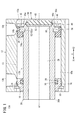
- FIG. 1 is a cross-sectional view of a fluid pressure cylinder including a rod assembly according to a first embodiment.
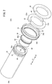
- FIG. 2 is a perspective view of the rod assembly.
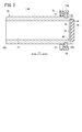
- FIG. 3 is a cross-sectional view of the rod assembly according to the second embodiment.
- FIG. 4 is a perspective view from the packing side of the rod assembly according to the second embodiment.
- FIG. 5 is a perspective view from the rod member side of the rod assembly according to the second embodiment.
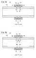
- 6A is a cross-sectional view of the rod assembly according to the third embodiment
- FIG. 6B is a cross-sectional view of the rod assembly according to the fourth embodiment
- FIG. 6C is a rod assembly according to the fifth embodiment.
- FIG. 7A is a cross-sectional view of the rod assembly according to the sixth embodiment
- FIG. 7B is a cross-sectional view of the rod assembly according to the seventh embodiment
- FIG. 8A is a cross-sectional view of the rod assembly according to the eighth embodiment
- FIG. 8B is a cross-sectional view of the rod assembly according to the ninth embodiment.
- FIG. 9A is a cross-sectional view of the rod assembly according to the tenth embodiment
- FIG. 9B is a cross-sectional view of the rod assembly according to the eleventh embodiment.
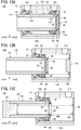
- FIG. 10A is a cross-sectional view of the rod assembly according to the twelfth embodiment
- FIG. 10B is a cross-sectional view of the rod assembly according to the thirteenth embodiment.
- FIG. 11A is a cross-sectional view of a rod assembly according to a fourteenth embodiment
- FIG. 11B is a perspective view of a first example of a rod tip member
- FIG. 11C is a perspective view of a second example of a rod tip member.
- FIG. 12 is a cross-sectional view of a fluid pressure cylinder including a rod assembly according to a fifteenth embodiment
- 13A is a cross-sectional view of a fluid pressure cylinder configured as a single-acting cylinder
- FIG. 13B is a cross-sectional view of another fluid pressure cylinder configured as a single-acting cylinder
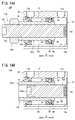
- FIG. 14A is a cross-sectional view of a fluid pressure cylinder including a rod assembly according to a seventeenth embodiment
- FIG. 14B is a cross-sectional view of a fluid pressure cylinder including a rod assembly according to an eighteenth embodiment.
- a fluid pressure cylinder 10 ⁇ / b> A shown in FIG. 1 includes a hollow cylindrical cylinder tube 12 (body), a head cover 14 disposed at one end of the cylinder tube 12, and the other end of the cylinder tube 12.
- a rod cover 16 disposed and a rod assembly 17A disposed so as to be reciprocally movable along the axial direction of the cylinder tube 12 are provided.
- the fluid pressure cylinder 10A is used as an actuator for conveying a workpiece, for example.
- the cylinder tube 12 is made of, for example, a metal material such as an aluminum alloy, and includes a cylinder that extends along the axial direction. In the present embodiment, the cylinder tube 12 is formed in a hollow cylindrical shape.
- the cylinder tube 12 includes a first port 12a provided on one end side in the axial direction (arrow X2 direction side), a second port 12b provided on the other end side in the axial direction (arrow X1 direction side), and a first A sliding hole 13 (cylinder chamber) communicating with the port 12a and the second port 12b is provided.
- the head cover 14 is, for example, a plate-like body made of the same metal material as the cylinder tube 12, and is provided so as to close one end portion (end portion on the X2 direction side) of the cylinder tube 12.
- One end of the cylinder tube 12 is hermetically closed by the head cover 14.
- the rod cover 16 is, for example, a circular ring-shaped member made of the same metal material as the cylinder tube 12, and is provided so as to close the other end portion (end portion on the X1 direction side) of the cylinder tube 12. Yes.
- An outer annular groove 24 is formed on the outer periphery of the rod cover 16.
- An outer seal member 26 made of an elastic material that seals between the outer peripheral surface of the rod cover 16 and the inner peripheral surface of the sliding hole 13 is attached to the outer annular groove 24.
- An inner annular groove 28 is formed on the inner periphery of the rod cover 16.
- An inner seal member 30 made of an elastic material that seals between the inner peripheral surface of the rod cover 16 and the outer peripheral surface of the rod member 20 is attached to the inner annular groove 28.
- the rod cover 16 is locked by a stopper 32 fixed to the inner peripheral portion on the other end side of the cylinder tube 12.
- the rod assembly 17 ⁇ / b> A includes a rod member 20 extending along the axial direction of the sliding hole 13, and a packing 34 attached to the outer peripheral portion of the rod member 20.
- the rod member 20 is formed in a hollow shape (in the first embodiment, a hollow cylindrical shape), and has a hollow portion 21 penetrating in the axial direction.
- the rod member 20 penetrates the rod cover 16.
- a distal end portion 20 b which is an end portion opposite to one end portion 20 a (hereinafter referred to as “base end portion 20 a”) of the rod member 20, is exposed to the outside of the sliding hole 13.
- Examples of the constituent material of the rod member 20 include metal materials such as carbon steel, stainless steel, and aluminum alloy, and hard resin.
- the packing 34 is accommodated in the cylinder tube 12 (sliding hole 13) so as to be slidable in the axial direction, and the first pressure chamber 13a on the first port 12a side and the second pressure on the second port 12b side in the sliding hole 13. It is divided into two pressure chambers 13b.
- the packing 34 is attached to the proximal end portion 20 a of the rod member 20.
- the packing 34 is an annular member that protrudes radially outward from the rod member 20.
- the outer diameter of the packing 34 is larger than the outer diameter of the rod member 20.
- An annular stopper mounting groove 50 and an annular magnet mounting groove 49 are provided in the outer peripheral portion of the rod member 20 in the vicinity of the base end portion 20a with an interval in the axial direction.
- the packing 34 is an annular seal member (for example, an O-ring) made of an elastic body attached to the outer peripheral portion of the rod member 20, and is disposed so as to surround the rod member 20.
- the constituent material of the packing 34 include elastic materials (urethane rubber and the like) such as a rubber material and an elastomer material.
- the outer peripheral surface of the packing 34 is in airtight or liquid-tight contact with the inner peripheral surface of the sliding hole 13 over the entire periphery.
- the inner peripheral surface of the packing 34 is in airtight or liquid tight contact with the outer peripheral portion (outer peripheral surface) of the rod member 20 over the entire periphery. For this reason, the packing 34 partitions the first pressure chamber 13a and the second pressure chamber 13b in the sliding hole 13 in an airtight or liquid tight manner.
- the packing 34 is mounted on the outer peripheral portion of the rod member 20, and the packing 34 partitions the first pressure chamber 13a and the second pressure chamber 13b in an airtight or liquid tight manner.
- the packing 34 has a pistonless structure in which a piston member made of a hard material is not provided.
- the packing 34 has a piston function.
- the packing 34 also serves as a damper (first damper) for reducing the impact when the stroke end of the rod cover 16 is reached.
- the packing 34 covers the stopper member 52 and is attached to the stopper member 52.
- the stopper member 52 is formed in an annular shape and is mounted in the stopper mounting groove 50 of the rod member 20.
- the packing 34 has a packing main body 34a that covers the rod cover 16 side (arrow X1 direction side) of the stopper member 52 and an outer peripheral covering portion 34b that covers the outer peripheral portion of the stopper member 52, and is formed in an L-shaped cross section. ing.
- the outer peripheral covering portion 34b protrudes in the axial direction from the outer peripheral portion of the packing main body portion 34a.
- the stopper member 52 includes a plurality of stopper elements 52a divided in the circumferential direction. Each stopper element 52a is formed in an arc shape.
- the stopper member 52 has a halved structure, and includes two semicircular arc-shaped stopper elements 52a.
- the inner peripheral portion of the stopper member 52 (the inner peripheral portion of the stopper element 52 a) is inserted into the stopper mounting groove 50.
- the stopper member 52 is made of a hard material, for example, the same material as the rod member 20 described above.
- the outer peripheral covering portion 34 b is attached to the outer peripheral portion of the stopper member 52. Thereby, the packing 34 is supported by the stopper member 52. Further, since the packing 34 is mounted on the stopper member 52, the stopper member 52 is prevented from being detached from the stopper mounting groove 50.
- An annular engagement groove 35 is provided on the inner peripheral portion of the outer peripheral covering portion 34b.
- the outer peripheral part of the stopper member 52 is engaged with the annular engaging groove 35 of the outer peripheral covering part 34b.
- the outer peripheral covering portion 34 b is pressed radially inward by the inner peripheral surface forming the sliding hole 13. For this reason, the outer periphery covering portion 34 b having the annular engagement groove 35 is prevented from being detached from the outer periphery of the stopper member 52.
- the rod member 20 and the packing 34 are capable of relative rotation about the axis a1 of the packing 34.
- the stopper member 52 and the packing 34 are mounted on the rod member 20 as follows. First, the two stopper elements 52a are individually mounted (fitted) in the stopper mounting groove 50 of the rod member 20 so as to form the annular stopper member 52. Next, the packing 34 is moved from the distal end 20b side to the proximal end 20a side of the rod member 20, and the packing 34 is placed on the stopper member 52 (two stopper elements 52a). Accordingly, the stopper member 52 is prevented from being detached from the stopper mounting groove 50, and the packing 34 is held at a predetermined position on the outer peripheral portion of the rod member 20.
- the magnet 48 is a circular ring-shaped member, and is mounted on the outer peripheral portion (magnet mounting groove 49) of the rod member 20.
- the magnet 48 is configured to be elastically deformable.
- the magnet 48 is a plastic magnet, and has a slit 54 (cut) in a part in the circumferential direction. For this reason, the magnet 48 can be easily mounted by being elastically deformed when mounted in the magnet mounting groove 49.
- the magnet 48 is disposed at a position adjacent to the packing 34.
- the end surface on the packing 34 side of the magnet 48 is in contact with the end surface on the magnet 48 side of the packing 34. Note that the end surface of the magnet 48 on the packing 34 side may not be in contact with the end surface of the packing 34 on the magnet 48 side.
- a magnetic sensor (not shown) is attached to the outer surface of the cylinder tube 12 at positions corresponding to both stroke ends of the packing 34 and the magnet 48. By sensing the magnetism generated by the magnet 48 with a magnetic sensor, the operating position of the rod assembly 17A is detected.
- a damper member 40 (second damper) is arranged at the base end portion 20a of the rod member 20 to alleviate an impact when reaching the stroke end on the head cover 14 side.
- the damper member 40 is mounted on the inner peripheral portion of the base end portion 20a of the rod member 20, and protrudes from the end surface 20c of the rod member 20 on the base end portion 20a side to the head cover 14 side (arrow X2 direction side).
- the damper member 40 is formed in a circular shape.
- the damper member 40 is provided with an annular (annular) flange portion 40a protruding outward in the radial direction.
- the flange portion 40 a is engaged with an annular engagement recess 58 provided on the inner peripheral portion of the proximal end portion 20 a of the rod member 20.
- the damper member 40 is prevented from being detached from the base end portion 20a of the rod member 20 by the engagement between the flange portion 40a and the annular engagement recess 58.
- the step part 60 is provided in the inner peripheral part of the base end part 20a of the rod member 20.
- a support member 62 is disposed on the step portion 60.
- the support member 62 is a circular plate member and is held between the stepped portion 60 and the damper member 40.
- the support member 62 supports the damper member 40 and prevents the damper member 40 from being bent by the pressure received from the pressure fluid. For this reason, the support member 62 is configured to be harder than the damper member 40.
- the support member 62 is made of a hard material, for example, the same material as the rod member 20 described above.
- the outer peripheral portion of the damper member 40 is in close contact with the inner peripheral portion of the rod member 20 over the entire periphery, so that the opening on the proximal end portion 20a side of the rod member 20 is airtight or liquid tight. Is closed. That is, the damper member 40 also serves as a seal member that closes the hollow portion 21 of the rod member 20 in an airtight or liquid tight manner.
- the fluid pressure cylinder 10A reciprocates the rod assembly 17A in the axial direction by the action of pressure fluid (for example, compressed air) introduced through the first port 12a or the second port 12b.
- pressure fluid for example, compressed air
- the second port 12b is opened to the atmosphere, and the pressure fluid is supplied from the pressure fluid supply source (not shown) via the first port 12a.
- One pressure chamber 13a is supplied.
- the rod assembly 17A is pushed toward the rod cover 16 by the pressure fluid. Thereby, the rod assembly 17A moves forward.
- the packing 34 comes into contact with the end face of the rod cover 16, the forward movement of the rod assembly 17A is stopped.
- the packing 34 is made of an elastic material, it is possible to effectively prevent the generation of impact and impact sound that accompany the rod assembly 17A reaching the advanced position (stroke end on the rod cover 16 side) or Can be suppressed.
- the first port 12a is opened to the atmosphere, and the pressure fluid is supplied from the pressure fluid supply source (not shown) through the second port 12b to the second pressure. Supply to chamber 13b. Then, the rod assembly 17A is pushed toward the head cover 14 by the pressure fluid. As a result, the rod assembly 17A moves backward (returns).
- the packing 34 is mounted on the outer peripheral portion of the rod member 20, the conventionally used hard piston member is eliminated, and the rod assembly 17A can be easily obtained. Can be assembled. This assembly can be easily performed manually without using a dedicated tool. Therefore, according to the rod assembly 17A of the present invention, assembly work can be simplified. Further, by increasing the outer diameter of the rod member 20, when moving to at least one side of the reciprocating operation in the sliding hole 13 (in the first embodiment, when moving to the head cover 14 side (backward)). ) Pressure fluid (air, etc.) consumption can be reduced.
- the outer peripheral portion of the rod member 20 is provided with a stopper mounting groove 50 extending in the circumferential direction, and the stopper mounting groove 50 is mounted with a plurality of stopper members 52 divided in the circumferential direction.
- the packing 34 covers the stopper member 52, whereby the packing 34 is supported by the stopper member 52 and the stopper member 52 is prevented from being detached from the stopper mounting groove 50. With this configuration, the packing 34 can be easily mounted on the outer periphery of the rod member 20 and the mounting state can be stably maintained.
- the packing 34 also serves as a damper that alleviates an impact when reaching one stroke end (on the rod cover 16 side in the first embodiment). For this reason, it is possible to satisfactorily prevent the impact load from being transmitted to the rod member 20 when one stroke end is reached.
- the rod member 20 is formed in a hollow shape. For this reason, weight reduction of the rod assembly 17A is achieved. And by reducing the weight of the rod assembly 17A, the amount of pressure fluid consumed can be reduced, and energy saving can be achieved.
- the rod member 20 and the packing 34 are relatively rotatable around the axis a1 of the packing 34. For this reason, the rod member 20 can be easily rotated when the fluid pressure cylinder 10A is installed in the facility, which is convenient.
- the point that the rod member 20 is rotatable is also the same for the rod assembly 17B (FIG. 3) provided with a polygonal packing 34A described later.
- the damper member 40 also serves as a seal member that closes the hollow portion 21 of the rod member 20 in an airtight or liquid tight manner. For this reason, compared with the structure which provides a damper and a sealing member as separate components, reduction of a number of parts is achieved.
- the present invention can be applied not only to the circular packing 34 described above but also to a polygonal packing 34A. Therefore, in the fluid pressure cylinder 10A, a rod assembly 17B having a polygonal packing 34A shown in FIGS. 3 to 5 may be employed instead of the rod assembly 17A having a circular packing 34.
- the packing 34A of the rod assembly 17B has an octagonal outer peripheral shape.
- the inner peripheral part shape of the packing 34A is formed in a circular shape.
- the packing 34A is provided with a plurality of magnet mounting grooves 70 at intervals in the circumferential direction. Specifically, the plurality of magnet mounting grooves 70 are provided on one surface of the packing 34A and have a depth in the axial direction of the packing 34A.
- a magnet 72 is mounted in one magnet mounting groove 70.
- the magnet 72 is, for example, a ferrite magnet or a rare earth magnet.
- the other parts of the rod assembly 17B are configured in the same manner as the rod assembly 17A.
- the rod member 20 having a hollow structure is adopted in the rod assembly 17A (FIG. 1) described above.
- the rod members 20A and 20B having a solid structure are used. May be adopted.
- FIG. 6A employs a rod member 20A modified to a solid structure in place of the rod member 20 of the rod assembly 17A (FIG. 1).
- the packing 34A of the rod assembly 17D in FIG. 6B extends in the axial direction from the outer periphery covering portion 34b of the packing 34 of the rod assembly 17A (FIG. 1), and has a magnet 48A (outer diameter than the magnet 48 shown in FIG. 1). Is provided with a magnet holding portion 74 for holding a magnet having a small inner diameter and a large inner diameter.
- the magnet 48A is held between the magnet holding part 74 and the outer periphery of the rod member 20B.
- a magnet holding annular groove 74 a is formed on the inner peripheral surface of the magnet holding portion 74.
- the outer periphery of the magnet 48A is fitted (engaged) with the magnet holding annular groove 74a.
- the rod assembly 17D employs a rod member 20B that is not provided with a magnet mounting groove on the outer periphery.
- the rod member 20A provided with the magnet mounting groove 49 on the outer peripheral portion and the packing 34A provided with the magnet holding portion 74 may be combined.
- the magnet 48B (a magnet having a smaller outer diameter than the magnet 48 shown in FIG. 1) is held between the magnet holding portion 74 and the magnet mounting groove 49.
- rod member 20 that protrudes long from the packing 34 only on one side is employed.
- Rod members 20C and 20D protruding on both sides of 34 and 34B may be employed.
- the rod assembly 17F shown in FIG. 7A includes a hollow rod member 20C in which two stopper mounting grooves 50 and one magnet mounting groove 49 are provided on the outer periphery, and two rod members 20C mounted on the outer periphery of the rod member 20C. Packing 34 is provided. The magnet mounting groove 49 is provided between the two stopper mounting grooves 50. A stopper member 52 is mounted in each of the two stopper mounting grooves 50. The packing 34 is attached to each of the two stopper members 52. A magnet 48 is disposed between the two packings 34.
- a hollow rod member 20D in which no magnet mounting groove is provided on the outer peripheral portion is employed.
- Two packings 34B each having an outer periphery covering portion 34c configured to extend in the axial direction from the outer periphery covering portion 34b of the packing 34 (FIG. 7A) are mounted on the outer periphery of the rod member 20D.
- each packing 34B has a magnet holding step 34d.
- the two packings 34B regulate the axial movement of the magnet 48C by holding a magnet 48C (a magnet having a smaller outer diameter and a larger inner diameter than the magnet 48 shown in FIG. 7A) between the magnet holding step portions 34d.
- the outer periphery of the magnet 48C is covered with the outer periphery covering portion 34c.
- rod members 20E and 20F having a solid structure projecting on both sides of the packings 34 and 34B may be employed.
- the damper member 40 is provided at the base end portion 20a of the rod member 20.
- the rod end portion 20a has a base end portion 20a.
- the damper member may not be provided.
- the opening on the proximal end portion 20a side of the rod member 20 is airtightly or liquid tightly closed by the seal member 76.
- the magnet 48 may be omitted from the rod assembly 17A (FIG. 1), and the rod assembly 17K shown in FIG. 9B may be configured.
- the rod assembly 17K employs a rod member 20G in which no magnet mounting groove is provided on the outer periphery.
- a rod member 20H having an annular wear ring mounting groove 86 provided on the outer peripheral portion is employed, and a wear ring 88 made of a low friction material is mounted on the wear ring mounting groove 86. May be.
- the wear ring 88 is an annular member for preventing the outer peripheral surface of the magnet 48 from coming into contact with the inner peripheral surface forming the sliding hole 13.
- Wear ring 88 is made of a low friction material.
- the low friction material include a synthetic resin material having both low friction and wear resistance such as tetrafluoroethylene (PTFE), a metal material (for example, bearing steel), and the like.
- a rod member 20I to which a magnet, a damper member, and a wear ring are not attached may be employed.
- a rod tip member 90 may be attached to the tip of the rod member 20 as in the rod assembly 17N shown in FIG. 11A.
- the rod tip member 90 includes a shaft portion 90b having a screw portion 90a (male screw) formed on the outer periphery, and a head portion 90c provided on the tip side of the shaft portion 90b. .
- the shaft portion 90b and the head portion 90c are integrally formed.
- the screw portion 90 a is screwed into the inner peripheral portion of the tip of the hollow rod member 20.
- a polygonal tool grip 90d that is gripped by a tightening tool is provided on the outer periphery of the head 90c.
- the rod member 20 is also provided with a tool gripping portion.
- a rod tip member 92 shown in FIG. 11C may be attached to the tip portion of the rod member 20.
- the rod tip member 92 includes a shaft portion 92b having a screw portion 92a (male screw) formed on the outer periphery, and a polygonal tool insertion hole 92c provided at an end portion of the shaft portion 92b.
- a fluid pressure cylinder 10B shown in FIG. 12 includes a hollow cylindrical cylinder tube 102 (body), a head cover 104 disposed at one end of the cylinder tube 102, and a rod cover 106 disposed at the other end of the cylinder tube 102.
- the fluid pressure cylinder 10 ⁇ / b> B further includes a rod assembly 17 ⁇ / b> O disposed so as to be able to reciprocate with respect to the cylinder tube 102, and a cushion mechanism 110 that alleviates an impact at one and the other stroke end.
- the rod assembly 170 includes a rod member 108 and a packing 34 attached to the rod member 108.
- the cylinder tube 102 is formed of a cylindrical body, and a sliding hole 103 (cylinder chamber) closed by the head cover 104 and the rod cover 106 is formed therein.
- the first stepped portion 112 of the head cover 104 is inserted into the end of the cylinder tube 102 on the arrow X2 direction side.
- the head cover 104 is formed with a first central cavity 116 and a first port 118 communicating with the first central cavity 116. Pressure fluid is supplied and discharged through the first port 118.
- the second stepped portion 120 of the rod cover 106 is inserted into the end of the cylinder tube 102 on the arrow X1 direction side.
- the rod cover 106 is formed with a second central cavity portion 124 and a second port 126 communicating with the second central cavity portion 124. Pressure fluid is supplied and discharged through the second port 126.
- a ring-shaped bush 130 and packing 132 are disposed on the inner peripheral portion of the rod cover 106.
- a packing 34 is attached to the outer peripheral portion of one end portion of the rod member 108 (hereinafter referred to as “base end portion 108a”).
- the packing 34 is disposed at an end of the first cushion member 140 described later on the head cover 104 side.
- the outer peripheral surface of the packing 34 is in contact with the inner peripheral surface forming the sliding hole 103 over the entire periphery.
- the inner peripheral surface of the packing 34 is in contact with the outer peripheral surface of the first cushion member 140 over the entire periphery.
- a stopper mounting groove 50 and a magnet mounting groove 49 are provided on the outer periphery of the rod member 108.
- a stopper member 52 is mounted in the stopper mounting groove 50.
- a magnet 48 is mounted in the magnet mounting groove 49.
- a damper member 40A is mounted on the base end portion 108a of the rod member 108.
- the damper member 40A is obtained by modifying the damper member 40 (FIG. 1) into a hollow shape.
- the cushion mechanism 110 includes a first cushion member 140 and a second cushion member 142 (cushion ring) provided on the movable portion (rod member 108) side, and an elasticity provided on the fixed portion (head cover 104 and rod cover 106) side. It has the ring-shaped 1st cushion seal 144 and 2nd cushion seal 146 which consist of members.
- the first cushion member 140 is provided coaxially with the rod member 108 at the end of the rod member 108 on the arrow X2 direction side. Specifically, the first cushion member 140 is formed with a smaller diameter than the rod member 108 and protrudes from the support member 62 and the damper member 40A in the direction of the arrow X2. The first cushion member 140 is formed in a hollow or solid cylindrical shape. The outer diameter of the first cushion member 140 is smaller than the outer diameter of the damper member 40A.
- the first cushion member 140 may be a part formed integrally with the rod member 108 or may be a separate part joined to the rod member 108. When the first cushion member 140 is a separate part from the rod member 108, the first cushion member 140 can be joined to the rod member 108 by joining means such as welding, adhesion, and screwing.
- the first cushion seal 144 is held on the inner periphery of the ring-shaped first holder 148.
- the first holder 148 is fixed to the inner peripheral portion of the first stepped portion 112 of the head cover 104.
- the sliding hole 103 and the first central cavity 116 communicate with each other via the hole 148a.
- the first cushion seal 144 is in sliding contact with the outer peripheral surface of the first cushion member 140 over the entire circumference.
- the second cushion member 142 is provided adjacent to the packing 34 and coaxially with the rod member 108.
- the second cushion member 142 is a ring-shaped member having a larger diameter than the rod member 108 and a smaller diameter than the packing 34, and is joined to the outer peripheral surface of the rod member 108 by, for example, welding, adhesion, or the like. .
- the outer diameter of the second cushion member 142 is slightly larger than the outer diameter of the rod member 108.
- the second cushion seal 146 is held on the inner periphery of the ring-shaped second holder 150.
- the second holder 150 is fixed to the inner peripheral portion of the second stepped portion 120 of the rod cover 106.
- the sliding hole 103 and the second central cavity 124 communicate with each other through the hole 150a.
- the second cushion seal 146 is in sliding contact with the outer peripheral surface of the second cushion member 142 over the entire circumference.
- the rod assembly 17 ⁇ / b> O moves forward and backward in the axial direction along the sliding hole 103 by the action of the pressure fluid introduced through the first port 118 or the second port 126.
- the second port 126 is opened to the atmosphere, and the first port 118 and the first central cavity portion are connected from a pressure fluid supply source (not shown). Air is supplied to the first pressure chamber 103a through 116 and the hole 148a. Thereby, the rod assembly 17O is displaced (advanced) toward the rod cover 106 side. In this case, the air in the second pressure chamber 103 b is discharged from the second port 126 through the hole 150 a of the second holder 150 and the second central cavity 124.
- the second cushion member 142 When the rod assembly 17O approaches the advanced position, the second cushion member 142 is inserted into the hole 150a of the second holder 150. Accordingly, the inner peripheral portion of the second cushion seal 146 contacts the outer peripheral surface of the second cushion member 142, and an airtight seal is formed at this contact portion.
- the air cushion of the second pressure chamber 103b serves as a displacement resistance of the rod assembly 17O, thereby decelerating the displacement of the rod assembly 17O near the stroke end on the rod cover 106 side. Therefore, the impact when the rod assembly 17O reaches the stroke end is further alleviated.
- the air is exhausted little by little to the second port 126 through a small hole (not shown).
- the first cushion member 140 When the rod assembly 17O approaches the retracted position, the first cushion member 140 is inserted into the hole 148a of the first holder 148. Accordingly, the inner peripheral portion of the first cushion seal 144 comes into contact with the outer peripheral surface of the first cushion member 140, and an airtight seal is formed at this contact portion.
- the air cushion of the first pressure chamber 103a serves as a displacement resistance when the rod assembly 17O is displaced toward the head cover 104, thereby decelerating the displacement of the rod assembly 17O near the stroke end on the head cover 104 side. Therefore, the impact when the rod assembly 17O reaches the stroke end is further alleviated.
- the fluid pressure cylinder 10C shown in FIG. 13A is configured as a so-called single acting cylinder. Specifically, the fluid pressure cylinder 10 ⁇ / b> C is obtained by arranging a spring 154 between the packing 34 and the rod cover 16 in the fluid pressure cylinder 10 ⁇ / b> A (FIG. 1). In this case, the second port 12b is open to the atmosphere.
- the rod assembly 17A In the fluid pressure cylinder 10C, when pressure fluid is supplied to the first pressure chamber 13a via the first port 12a, the rod assembly 17A is displaced (advanced) toward the rod cover 16 by the pressure fluid, and the stroke end at the advance position is reached. To reach. When the supply of pressurized fluid to the first port 12a is stopped and the first port 12a is opened to the atmosphere, the rod assembly 17A is displaced (retracted) toward the head cover 14 by the elastic biasing force of the spring 154, and retracted. The stroke end of the position is reached.
- the fluid pressure cylinder 10D shown in FIG. 13B is also configured as a so-called single-acting cylinder. Specifically, the fluid pressure cylinder 10 ⁇ / b> D is obtained by arranging a spring 154 between the packing 34 and the head cover 14 in the fluid pressure cylinder 10 ⁇ / b> A (FIG. 1). In this case, the first port 12a is open to the atmosphere.
- the fluid pressure cylinder 10E shown in FIG. 13C is also configured as a so-called single acting cylinder.
- the fluid pressure cylinder 10E includes a rod assembly 17P.
- the damper member 40B attached to the proximal end portion of the rod member 20 is formed in an annular shape.
- the rod tip member 94 is attached to the tip of the rod member 20.
- the rod tip member 94 may be configured similarly to the rod tip member 90 (FIG. 11B) or the rod tip member 92 (FIG. 11C) described above.
- a spring 156 is inserted into the hollow portion of the rod member 20.
- the spring 156 is disposed between the rod tip member 94 and the head cover 14.
- the fluid pressure cylinder 10E configured as described above operates in the same manner as the fluid pressure cylinder 10D described above.
- the rod assembly 17Q of the fluid pressure cylinder 10F shown in FIG. 14A includes a hollow rod member 20J having an internal thread portion 160 formed on the inner peripheral surface, a packing 34 attached to the outer peripheral portion of the rod member 20J, And an adjustment bolt 162 that is inserted into the member 20J and screwed into the rod member 20J.
- a male screw portion 163 that is screwed into the female screw portion 160 is formed on the outer periphery of the adjustment bolt 162.
- the adjustment bolt 162 protrudes from the rod member 20J in the distal direction (arrow X1 direction).
- An adjustment nut 164 is screwed to the adjustment bolt 162 on the tip side of the rod member 20J.
- a damper member 40 is attached to the proximal end portion of the rod member 20J.
- the amount of pull-in of the rod member 20J into the cylinder tube 12 is adjusted by adjusting the protruding length of the adjusting bolt 162 protruding from the rod member 20J to the head cover 14 side. Can be adjusted.
- an adjustment bolt 166 shorter than the adjustment bolt 162 (FIG. 14A) described above is employed.
- the tip end portion 166a of the adjustment bolt 166 is located in the hollow portion of the rod member 20J.
- a male threaded portion 163 is not formed at the distal end portion 166a of the adjustment bolt 166, and the outer diameter of the distal end portion 166a is smaller than the outer diameter of the portion where the male threaded portion 163 is provided.
- the present invention is not limited to the above-described embodiment, and various modifications can be made without departing from the gist of the present invention.
- the present invention can also be applied to a fluid pressure cylinder in which the cross-sectional shapes of the piston unit and the cylinder tube are non-circular (rectangular, elliptical, etc.) (the rod assembly 17B in FIG. One example).
- the present invention can also be applied to a multi-rod type (dual rod type or the like) fluid pressure cylinder having a plurality of pistons and piston rods.
- the present invention is not limited to a fluid pressure cylinder used as an actuator or the like, but can be applied to other forms of fluid pressure devices having a piston.
- Other forms of fluid pressure devices having a piston to which the present invention can be applied include, for example, a valve device that switches a flow path by moving a valve body by a piston, and a piston that is connected to the piston rod as an input shaft.
- a measuring cylinder that measures the length by displacing it, a slide table that displaces the table that is connected to the piston via the piston rod by displacing the piston, and a grip that opens and closes by displacing the piston and converting this piston displacement
- a chuck device for gripping a workpiece by the portion.
Landscapes
- Engineering & Computer Science (AREA)
- General Engineering & Computer Science (AREA)
- Mechanical Engineering (AREA)
- Physics & Mathematics (AREA)
- Fluid Mechanics (AREA)
- Actuator (AREA)
- Sealing Devices (AREA)
- Vibration Dampers (AREA)
- Chemical & Material Sciences (AREA)
- Analytical Chemistry (AREA)
- Fluid-Damping Devices (AREA)
Abstract
Description
Claims (12)
- 流体圧装置の摺動孔(13、103)に沿って往復動作するロッド組立体(17A~17R)であって、
ロッド部材(20、20A~20J、108)と、
前記ロッド部材(20、20A~20J、108)の外周部に装着され、前記摺動孔(13、103)に沿って摺動するパッキン(34、34A、34B)と、を備える、
ことを特徴とするロッド組立体(17A~17R)。 - 請求項1記載のロッド組立体(17A~17R)において、
前記ロッド部材(20、20A~20J、108)の前記外周部には、周方向に延在するストッパ装着溝(50)が設けられ、
前記ストッパ装着溝(50)には、周方向に複数に分割されたストッパ部材(52)が装着されており、
前記パッキン(34、34A、34B)は前記ストッパ部材(52)を覆っており、これにより、前記パッキン(34、34A、34B)が前記ストッパ部材(52)により支持されるとともに前記ストッパ部材(52)が前記ストッパ装着溝(50)から離脱することが阻止されている、
ことを特徴とするロッド組立体(17A~17R)。 - 請求項1記載のロッド組立体(17A~17R)において、
前記パッキン(34、34A、34B)は、ストロークエンド到達時の衝撃を緩和するダンパを兼ねる、
ことを特徴とするロッド組立体(17A~17R)。 - 請求項1記載のロッド組立体において、
前記ロッド部材は、中空状に形成されている、
ことを特徴とするロッド組立体。 - 請求項4記載のロッド組立体において、
前記ロッド部材の一端部には、ストロークエンド到達時の衝撃を緩和するダンパ部材(40、40A、40B)が装着されており、
前記ダンパ部材(40、40A、40B)は、前記ロッド部材の中空部を気密又は液密に閉塞している、
ことを特徴とするロッド組立体。 - 請求項5記載のロッド組立体において、
前記ダンパ部材(40、40A、40B)の外周部は、前記ロッド部材の内周部に装着されている、
ことを特徴とするロッド組立体。 - 請求項5記載のロッド組立体において、
前記ロッド部材の中空部には、前記ダンパ部材(40、40A、40B)よりも硬質に構成されるとともに前記ダンパ部材(40、40A、40B)を支持する支持部材(62)が配置されている、
ことを特徴とするロッド組立体。 - 請求項1記載のロッド組立体において、
前記ロッド部材の外周部には、マグネット装着溝(49)が設けられ、
前記マグネット装着溝(49)に環状のマグネット(48、48A)が装着されている、
ことを特徴とするロッド組立体。 - 請求項1記載のロッド組立体(17B)において、
パッキン(34A)には、軸方向に深さを有する少なくとも1つのマグネット装着溝(70)が設けられ、
前記少なくとも1つのマグネット装着溝(70)にマグネット(72)が装着されている、
ことを特徴とするロッド組立体(17B)。 - 請求項9記載のロッド組立体(17B)において、
前記パッキン(34A)の外周形状は、非円形形状であり、
前記少なくとも1つのマグネット装着溝(70)は、周方向に間隔を置いて設けられた複数のマグネット装着溝(70)を有し、
前記複数のマグネット装着溝(70)の一部のみに、前記マグネット(72)が装着されている、
ことを特徴とするロッド組立体(17B)。 - 内部に摺動孔(13、103)を有するボディと、
前記摺動孔(13、103)に沿って往復移動可能に配置されたロッド組立体(17A~17R)と、を備え、
前記ロッド組立体(17A~17R)は、ロッド部材(20、20A~20J、108)と、前記ロッド部材(20、20A~20J、108)の外周部に装着され、前記摺動孔(13、103)に沿って摺動するパッキン(34、34A、34B)とを有する、
ことを特徴とする流体圧装置。 - 請求項11記載の流体圧装置において、
前記流体圧装置は、流体圧シリンダ(10A~10G)、バルブ装置、測長シリンダ、スライドテーブル又はチャック装置として構成されている、
ことを特徴とする流体圧装置。
Priority Applications (7)
| Application Number | Priority Date | Filing Date | Title |
|---|---|---|---|
| KR1020197019428A KR102257340B1 (ko) | 2016-12-06 | 2017-11-13 | 로드 조립체 및 유체압 장치 |
| CN201780075333.2A CN110050129B (zh) | 2016-12-06 | 2017-11-13 | 杆组装体及流体压力装置 |
| US16/466,549 US11143214B2 (en) | 2016-12-06 | 2017-11-13 | Rod assembly and fluid pressure device |
| MX2019006430A MX2019006430A (es) | 2016-12-06 | 2017-11-13 | Montaje de varilla y dispositivo de fluido a presion. |
| RU2019120895A RU2019120895A (ru) | 2016-12-06 | 2017-11-13 | Штоковый узел и гидро(пневмо)устройство |
| EP17878720.6A EP3553327B1 (en) | 2016-12-06 | 2017-11-13 | Rod assembly and fluid pressure device |
| BR112019011485A BR112019011485A2 (pt) | 2016-12-06 | 2017-11-13 | conjunto de haste e dispositivo de pressão de fluidos |
Applications Claiming Priority (2)
| Application Number | Priority Date | Filing Date | Title |
|---|---|---|---|
| JP2016236470A JP6598079B2 (ja) | 2016-12-06 | 2016-12-06 | ロッド組立体及び流体圧装置 |
| JP2016-236470 | 2016-12-06 |
Publications (1)
| Publication Number | Publication Date |
|---|---|
| WO2018105315A1 true WO2018105315A1 (ja) | 2018-06-14 |
Family
ID=62491183
Family Applications (1)
| Application Number | Title | Priority Date | Filing Date |
|---|---|---|---|
| PCT/JP2017/040680 Ceased WO2018105315A1 (ja) | 2016-12-06 | 2017-11-13 | ロッド組立体及び流体圧装置 |
Country Status (10)
| Country | Link |
|---|---|
| US (1) | US11143214B2 (ja) |
| EP (1) | EP3553327B1 (ja) |
| JP (1) | JP6598079B2 (ja) |
| KR (1) | KR102257340B1 (ja) |
| CN (1) | CN110050129B (ja) |
| BR (1) | BR112019011485A2 (ja) |
| MX (1) | MX2019006430A (ja) |
| RU (1) | RU2019120895A (ja) |
| TW (1) | TWI659162B (ja) |
| WO (1) | WO2018105315A1 (ja) |
Families Citing this family (5)
| Publication number | Priority date | Publication date | Assignee | Title |
|---|---|---|---|---|
| DE102016007593A1 (de) * | 2016-06-21 | 2017-12-21 | Liebherr-Components Kirchdorf GmbH | Verfahren zur Herstellung einer Kolbenstangen-Einheit sowie Kolbenstangen-Einheit |
| JP6751916B2 (ja) * | 2018-03-23 | 2020-09-09 | Smc株式会社 | 流体圧シリンダ |
| JP7137163B2 (ja) * | 2018-09-13 | 2022-09-14 | Smc株式会社 | 流体圧シリンダ |
| CN110864030B (zh) * | 2019-11-01 | 2024-11-05 | 江南工业集团有限公司 | 一种密闭产品压力试验控制装置及控制方法 |
| CN111911631B (zh) * | 2020-08-10 | 2022-06-10 | 常德市联嘉机械有限公司 | 一种可用于高压环境下的双向活塞密封结构 |
Citations (4)
| Publication number | Priority date | Publication date | Assignee | Title |
|---|---|---|---|---|
| JPH01171905U (ja) * | 1988-05-26 | 1989-12-06 | ||
| JPH0380109U (ja) * | 1989-12-05 | 1991-08-16 | ||
| US20060162551A1 (en) * | 2005-01-25 | 2006-07-27 | Festo Ag & Co. | Piston and a power cylinder fitted therewith |
| JP2014114874A (ja) | 2012-12-10 | 2014-06-26 | Smc Corp | 流体圧シリンダ |
Family Cites Families (31)
| Publication number | Priority date | Publication date | Assignee | Title |
|---|---|---|---|---|
| US2493602A (en) * | 1947-12-31 | 1950-01-03 | Vance C Sterrett | Pressure fluid motor |
| US2981232A (en) * | 1957-04-10 | 1961-04-25 | Renault | Differential pressure pneumatic jacks adapted for automatic return to initial position |
| GB1103118A (en) | 1964-02-13 | 1968-02-14 | Walter Douglass | Improvements in or relating to fluid actuated magnetic switches |
| DE2730112C2 (de) * | 1977-07-04 | 1982-04-15 | Festo-Maschinenfabrik Gottlieb Stoll, 7300 Esslingen | Kolbenanordnung, insbesondere für Trockenlaufkompressoren |
| DE3249183C2 (de) * | 1981-11-19 | 1986-11-13 | Special'noe konstruktorsko-technologičeskoe bjuro Glavmosinžstroja pri Mosgorispolkome, Moskau/Moskva | Dichtungsanordnung, insbesondere für einen hydraulischen Hebebock |
| DE8209420U1 (de) | 1982-04-02 | 1983-09-15 | Robert Bosch Gmbh, 7000 Stuttgart | Kolben fuer beruehrungslose abtastung der kolbenstellung |
| JP2531830Y2 (ja) | 1989-09-01 | 1997-04-09 | シーケーディ 株式会社 | シリンダの緩衝構造 |
| JPH0632495U (ja) | 1992-09-28 | 1994-04-28 | 日本輸送機株式会社 | フルフリーマスト装置における緩衝装置 |
| DE9416082U1 (de) | 1994-10-06 | 1994-12-08 | Kuhnke GmbH, 23714 Malente | Kolben-Zylinder-Anordnung |
| DE29607993U1 (de) * | 1996-05-03 | 1996-08-01 | Festo Kg, 73734 Esslingen | Kolben für einen Arbeitszylinder |
| IT1285781B1 (it) | 1996-10-11 | 1998-06-18 | Giacomo Bardoni | Attuatore elettro-pneumatico |
| US5947001A (en) * | 1997-04-24 | 1999-09-07 | Turn-Act, Inc. | Molded piston |
| JPH11132204A (ja) | 1997-10-31 | 1999-05-18 | Taiyo Ltd | シリンダ装置 |
| JP3469525B2 (ja) * | 2000-03-03 | 2003-11-25 | Smc株式会社 | クッション機構付空気圧ロータリアクチュエータ |
| JP3803068B2 (ja) * | 2001-06-05 | 2006-08-02 | 有限会社有泉設計 | 流体圧シリンダ |
| DE202005005508U1 (de) * | 2005-04-07 | 2005-06-02 | Festo Ag & Co. | Kolben und damit ausgestattete fluidbetätigte Stellvorrichtung |
| CA2507149A1 (en) * | 2005-05-12 | 2006-11-12 | P & M Design & Consulting Ltd. | Pneumatic cylinder |
| JP4453023B2 (ja) | 2005-06-20 | 2010-04-21 | Smc株式会社 | 位置検出装置付き流体圧シリンダ |
| KR100777412B1 (ko) | 2006-07-11 | 2007-11-19 | 한국기계연구원 | 피스톤 로드의 상대 거리 계측이 가능한 실린더 |
| DE102006040085A1 (de) | 2006-08-28 | 2008-03-20 | Zimmer, Günther | Kostengünstig herstellbare pneumatische Verzögerungsvorrichtung |
| DE102007016431A1 (de) * | 2007-04-05 | 2008-10-09 | Festo Ag & Co. Kg | Fluidbetätigter Linearantrieb |
| JP5212773B2 (ja) * | 2007-09-11 | 2013-06-19 | Smc株式会社 | 流体圧シリンダ |
| JP2013024302A (ja) * | 2011-07-19 | 2013-02-04 | Komatsu Ltd | 油圧シリンダ |
| CN102518618A (zh) | 2011-12-27 | 2012-06-27 | 山东天一液压科技股份有限公司 | 一种液压油缸 |
| CN202646222U (zh) * | 2012-05-23 | 2013-01-02 | 三一重工股份有限公司 | 油缸及液压系统 |
| JP6028994B2 (ja) * | 2012-06-18 | 2016-11-24 | Smc株式会社 | 流体圧シリンダ |
| DE202012008999U1 (de) | 2012-09-19 | 2014-01-15 | Bümach Engineering International B.V. | Kolbeneinheit eines Arbeitszylinders |
| DE102013008408A1 (de) | 2013-05-16 | 2014-11-20 | Festo Ag & Co. Kg | Antriebseinheit eines fluidbetätigten Linearantriebes und Verfahren zu ihrer Herstellung |
| CN204083234U (zh) * | 2014-08-26 | 2015-01-07 | 优泰科(苏州)密封技术有限公司 | 一种活塞密封件 |
| CN104895862B (zh) * | 2015-05-18 | 2017-01-25 | 无锡亿利大机械有限公司 | 具有位移传感器的液压油缸 |
| CN205118244U (zh) | 2015-10-28 | 2016-03-30 | 上虞市神龙铝塑制品有限公司 | 活塞杆与活塞密封结构 |
-
2016
- 2016-12-06 JP JP2016236470A patent/JP6598079B2/ja active Active
-
2017
- 2017-11-13 RU RU2019120895A patent/RU2019120895A/ru unknown
- 2017-11-13 MX MX2019006430A patent/MX2019006430A/es unknown
- 2017-11-13 US US16/466,549 patent/US11143214B2/en active Active
- 2017-11-13 WO PCT/JP2017/040680 patent/WO2018105315A1/ja not_active Ceased
- 2017-11-13 BR BR112019011485A patent/BR112019011485A2/pt not_active Application Discontinuation
- 2017-11-13 EP EP17878720.6A patent/EP3553327B1/en active Active
- 2017-11-13 KR KR1020197019428A patent/KR102257340B1/ko active Active
- 2017-11-13 CN CN201780075333.2A patent/CN110050129B/zh active Active
- 2017-12-01 TW TW106142187A patent/TWI659162B/zh active
Patent Citations (4)
| Publication number | Priority date | Publication date | Assignee | Title |
|---|---|---|---|---|
| JPH01171905U (ja) * | 1988-05-26 | 1989-12-06 | ||
| JPH0380109U (ja) * | 1989-12-05 | 1991-08-16 | ||
| US20060162551A1 (en) * | 2005-01-25 | 2006-07-27 | Festo Ag & Co. | Piston and a power cylinder fitted therewith |
| JP2014114874A (ja) | 2012-12-10 | 2014-06-26 | Smc Corp | 流体圧シリンダ |
Non-Patent Citations (1)
| Title |
|---|
| See also references of EP3553327A4 |
Also Published As
| Publication number | Publication date |
|---|---|
| EP3553327A4 (en) | 2020-07-29 |
| JP2018091440A (ja) | 2018-06-14 |
| KR102257340B1 (ko) | 2021-05-27 |
| MX2019006430A (es) | 2019-08-21 |
| JP6598079B2 (ja) | 2019-10-30 |
| TWI659162B (zh) | 2019-05-11 |
| EP3553327B1 (en) | 2024-01-24 |
| US20200072254A1 (en) | 2020-03-05 |
| KR20190089992A (ko) | 2019-07-31 |
| CN110050129B (zh) | 2021-01-26 |
| EP3553327A1 (en) | 2019-10-16 |
| CN110050129A (zh) | 2019-07-23 |
| US11143214B2 (en) | 2021-10-12 |
| BR112019011485A2 (pt) | 2019-10-22 |
| RU2019120895A (ru) | 2021-01-12 |
| TW201827717A (zh) | 2018-08-01 |
| RU2019120895A3 (ja) | 2021-01-12 |
Similar Documents
| Publication | Publication Date | Title |
|---|---|---|
| JP6598079B2 (ja) | ロッド組立体及び流体圧装置 | |
| CN111094765B (zh) | 流体压力缸 | |
| RU2731197C9 (ru) | Соединительная конструкция вала и гидро(пневмо)устройство | |
| US11079017B2 (en) | Hydraulic cylinder | |
| US10718360B2 (en) | Hydraulic fluid device | |
| US11371538B2 (en) | Fluid pressure cylinder | |
| US11215204B2 (en) | Piston unit and hydraulic cylinder | |
| US11280409B2 (en) | Method for producing piston assembly and hydraulic fluid device | |
| JP6598083B2 (ja) | ピストン組立体及び流体圧装置 | |
| WO2018105314A1 (ja) | ピストン組立体及び流体圧装置 |
Legal Events
| Date | Code | Title | Description |
|---|---|---|---|
| 121 | Ep: the epo has been informed by wipo that ep was designated in this application |
Ref document number: 17878720 Country of ref document: EP Kind code of ref document: A1 |
|
| NENP | Non-entry into the national phase |
Ref country code: DE |
|
| REG | Reference to national code |
Ref country code: BR Ref legal event code: B01A Ref document number: 112019011485 Country of ref document: BR |
|
| ENP | Entry into the national phase |
Ref document number: 20197019428 Country of ref document: KR Kind code of ref document: A |
|
| ENP | Entry into the national phase |
Ref document number: 2017878720 Country of ref document: EP Effective date: 20190708 |
|
| ENP | Entry into the national phase |
Ref document number: 112019011485 Country of ref document: BR Kind code of ref document: A2 Effective date: 20190604 |