WO2018105551A1 - 放射温度測定装置 - Google Patents
放射温度測定装置 Download PDFInfo
- Publication number
- WO2018105551A1 WO2018105551A1 PCT/JP2017/043454 JP2017043454W WO2018105551A1 WO 2018105551 A1 WO2018105551 A1 WO 2018105551A1 JP 2017043454 W JP2017043454 W JP 2017043454W WO 2018105551 A1 WO2018105551 A1 WO 2018105551A1
- Authority
- WO
- WIPO (PCT)
- Prior art keywords
- polarizing plate
- temperature measuring
- radiation temperature
- infrared sensor
- electromagnetic wave
- Prior art date
- Legal status (The legal status is an assumption and is not a legal conclusion. Google has not performed a legal analysis and makes no representation as to the accuracy of the status listed.)
- Ceased
Links
Images


Classifications
-
- G—PHYSICS
- G01—MEASURING; TESTING
- G01J—MEASUREMENT OF INTENSITY, VELOCITY, SPECTRAL CONTENT, POLARISATION, PHASE OR PULSE CHARACTERISTICS OF INFRARED, VISIBLE OR ULTRAVIOLET LIGHT; COLORIMETRY; RADIATION PYROMETRY
- G01J5/00—Radiation pyrometry, e.g. infrared or optical thermometry
- G01J5/02—Constructional details
- G01J5/06—Arrangements for eliminating effects of disturbing radiation; Arrangements for compensating changes in sensitivity
-
- G—PHYSICS
- G01—MEASURING; TESTING
- G01J—MEASUREMENT OF INTENSITY, VELOCITY, SPECTRAL CONTENT, POLARISATION, PHASE OR PULSE CHARACTERISTICS OF INFRARED, VISIBLE OR ULTRAVIOLET LIGHT; COLORIMETRY; RADIATION PYROMETRY
- G01J5/00—Radiation pyrometry, e.g. infrared or optical thermometry
- G01J5/02—Constructional details
- G01J5/08—Optical arrangements
- G01J5/0808—Convex mirrors
-
- G—PHYSICS
- G01—MEASURING; TESTING
- G01J—MEASUREMENT OF INTENSITY, VELOCITY, SPECTRAL CONTENT, POLARISATION, PHASE OR PULSE CHARACTERISTICS OF INFRARED, VISIBLE OR ULTRAVIOLET LIGHT; COLORIMETRY; RADIATION PYROMETRY
- G01J5/00—Radiation pyrometry, e.g. infrared or optical thermometry
- G01J5/02—Constructional details
- G01J5/08—Optical arrangements
- G01J5/0813—Planar mirrors; Parallel phase plates
-
- G—PHYSICS
- G01—MEASURING; TESTING
- G01J—MEASUREMENT OF INTENSITY, VELOCITY, SPECTRAL CONTENT, POLARISATION, PHASE OR PULSE CHARACTERISTICS OF INFRARED, VISIBLE OR ULTRAVIOLET LIGHT; COLORIMETRY; RADIATION PYROMETRY
- G01J5/00—Radiation pyrometry, e.g. infrared or optical thermometry
- G01J5/10—Radiation pyrometry, e.g. infrared or optical thermometry using electric radiation detectors
-
- G—PHYSICS
- G01—MEASURING; TESTING
- G01J—MEASUREMENT OF INTENSITY, VELOCITY, SPECTRAL CONTENT, POLARISATION, PHASE OR PULSE CHARACTERISTICS OF INFRARED, VISIBLE OR ULTRAVIOLET LIGHT; COLORIMETRY; RADIATION PYROMETRY
- G01J5/00—Radiation pyrometry, e.g. infrared or optical thermometry
- G01J5/59—Radiation pyrometry, e.g. infrared or optical thermometry using polarisation; Details thereof
-
- G—PHYSICS
- G02—OPTICS
- G02B—OPTICAL ELEMENTS, SYSTEMS OR APPARATUS
- G02B5/00—Optical elements other than lenses
- G02B5/30—Polarising elements
-
- G—PHYSICS
- G02—OPTICS
- G02B—OPTICAL ELEMENTS, SYSTEMS OR APPARATUS
- G02B5/00—Optical elements other than lenses
- G02B5/30—Polarising elements
- G02B5/3025—Polarisers, i.e. arrangements capable of producing a definite output polarisation state from an unpolarised input state
- G02B5/3058—Polarisers, i.e. arrangements capable of producing a definite output polarisation state from an unpolarised input state comprising electrically conductive elements, e.g. wire grids, conductive particles
-
- G—PHYSICS
- G01—MEASURING; TESTING
- G01J—MEASUREMENT OF INTENSITY, VELOCITY, SPECTRAL CONTENT, POLARISATION, PHASE OR PULSE CHARACTERISTICS OF INFRARED, VISIBLE OR ULTRAVIOLET LIGHT; COLORIMETRY; RADIATION PYROMETRY
- G01J5/00—Radiation pyrometry, e.g. infrared or optical thermometry
- G01J5/60—Radiation pyrometry, e.g. infrared or optical thermometry using determination of colour temperature
- G01J5/602—Radiation pyrometry, e.g. infrared or optical thermometry using determination of colour temperature using selective, monochromatic or bandpass filtering
- G01J2005/604—Radiation pyrometry, e.g. infrared or optical thermometry using determination of colour temperature using selective, monochromatic or bandpass filtering bandpass filtered
-
- G—PHYSICS
- G01—MEASURING; TESTING
- G01J—MEASUREMENT OF INTENSITY, VELOCITY, SPECTRAL CONTENT, POLARISATION, PHASE OR PULSE CHARACTERISTICS OF INFRARED, VISIBLE OR ULTRAVIOLET LIGHT; COLORIMETRY; RADIATION PYROMETRY
- G01J5/00—Radiation pyrometry, e.g. infrared or optical thermometry
- G01J5/48—Thermography; Techniques using wholly visual means
Definitions
- the present invention relates to a radiation temperature measuring device using an infrared sensor.
- a temperature measuring device that measures the temperature of an object in a non-contact manner using an infrared sensor.
- the application product examples are a radiation thermometer (non-contact thermometer), a thermography (infrared camera), and the like.
- a temperature measuring device uses the principle that the radiated electromagnetic energy of an object is determined only by the temperature of the object. That is, if an infrared sensor is used, the radiant energy in the infrared wavelength band that occupies most of the radiated electromagnetic wave energy of the object can be measured. The temperature of the object is calculated from the measured value of the radiant energy. For example, Stefan Boltzmann's law concerning black body radiation is used for the calculation of the temperature of the object.
- Non-Patent Document 1 describes a technique for overcoming the problem of reflection that occurs when measuring the temperature of an object.
- glass, tiles, and the like whose main component is silicon oxide (SiO 2 ) have a very high reflectance at a wavelength of about 8 to 15 ⁇ m.
- Non-Patent Document 1 describes that this reflectance is about 30% at the maximum.
- the reflectance of glass with respect to infrared rays having a wavelength of 5 to 8 ⁇ m is 3 to 4% on average. Therefore, even with the technique described in Non-Patent Document 1, the influence of reflection can only be reduced somewhat, and cannot be reduced to zero. That is, the component reflected by the electromagnetic wave affects the measurement of the infrared sensor.
- a polarizing plate is well known as a product that prevents reflection of electromagnetic waves at such an interface.
- the most famous usage of this polarizing plate is polarized sunglasses, which can reduce the reflected light generated on the surface of the fish near the fisherman.
- the polarizing plate is most often used in the visible light wavelength band (wavelength of about 400 to 800 nm) among electromagnetic waves, and is often applied in the near infrared band (wavelength of about 800 nm to 1.5 ⁇ m). .
- Patent Document 1 discloses one specific method of using a polarizing plate.
- Unpolarized normal light near-infrared rays in Patent Document 1 directed to a polarizing plate (in the case of Patent Document 1, a wire grid polarizing film having a fixed polarization axis) Is transmitted in the intrinsic axial direction, and reflected in the direction perpendicular to the axial direction.
- the electromagnetic wave energy of both the polarized light transmission component and the polarized light reflection component is measured with a light receiver.
- the apparatus disclosed in Patent Document 1 is not an apparatus for measuring temperature.
- Patent Document 2 discloses an apparatus for measuring temperature while using a polarizing plate. However, this apparatus measures the temperature of the object to be measured by measuring two polarization components using a polarizing plate in order to minimize the influence of the vibration when the object to be measured is physically vibrating. It is a technology that demands. In Patent Document 2, there is no mention or suggestion of the reflectance of the measurement object (measurement object) and the phenomenon of reflection itself.
- the wire grid polarizing film described above is made of a polymer material, in the near infrared band, the absorption mode of the material substrate appears, so the transmittance is very small, and there is also a wavelength band with zero transmittance. To do. Therefore, since the transmittance is very small, the measurement output of the transmitted polarized light becomes very small. In other words, the transmission type electromagnetic wave measurement similar to that of the polarized sunglasses described above is difficult to measure at least in the infrared band where the radiation temperature is measured.
- the object of the present invention is to detect a sufficiently large output level even in the infrared wavelength band optimal for radiation temperature measurement, and to prevent a decrease in temperature measurement accuracy even for an object having a high reflectance of the measurement object.
- An object of the present invention is to provide a radiation temperature measuring device capable of performing the above.
- the present invention it is possible to detect a sufficiently large output level even in an infrared wavelength band that is optimal for radiation temperature measurement, and it is possible to measure the temperature measurement accuracy even for an object having a high reflectance of the measurement object. Decline can be prevented.
- FIG. 3 is a diagram for explaining a radiation temperature measuring apparatus 100 according to an embodiment of the present invention, and is a schematic diagram of a cross section obtained by cutting the reflective polarizing plate 2 along the line AA shown in FIG. 2.
- FIG. 1 is a block diagram illustrating a schematic configuration example of a radiation temperature measuring apparatus 100 according to the present embodiment.
- the radiation temperature measuring apparatus 100 is an apparatus that measures the surface temperature of an object to be measured in a non-contact manner using an infrared sensor.
- the infrared sensor preferably has a wavelength band in the mid-infrared band (4-8 ⁇ m) instead of the conventional far-infrared band (8-15 ⁇ m).
- the reflective polarizing plate 2 is a reflective polarizing plate.
- the reflection type polarizing plate is a polarizing plate having an action of reflecting one of electromagnetic waves.
- a general polarizing plate has a function of transmitting or absorbing polarized electromagnetic waves to be separated, but does not necessarily have a function of reflecting.
- An example of a material that does not have a function of being reflected is an iodine-type polarizing plate often used for a liquid crystal display.
- examples of the polarizing plate having an action to be reflected include a wire grid polarizing film (hereinafter abbreviated as “WGF”) and a laminated polarizing film.
- WGF wire grid polarizing film
- the radiation temperature measuring device 100 includes a housing 3 in which the infrared sensor 1 and the reflective polarizing plate 2 are integrated.
- the housing 3 mainly suppresses the first role of combining the infrared sensor 1 and the reflective polarizing plate 2 with specified dimensions, and disturbance (stray light) entering the infrared sensor 1 by the infrared absorption action of the housing 3. It plays the second role.
- the radiation temperature measuring device 100 further includes a temperature conversion unit 4 that converts the detection signal of the infrared sensor 1 into a temperature.
- the temperature conversion unit 4 may be provided outside the housing 3 as illustrated in FIG. 1, or may be provided inside the housing 3.
- the temperature measurement object 101 is a temperature measurement object whose temperature is measured by the radiation temperature measurement device 100, and is arranged at a place different from the radiation temperature measurement device 100.
- the temperature measurement object 101 may be basically anything, for example, a black body.
- the radiation temperature measuring apparatus 100 according to the present embodiment is more effective as the temperature measurement object 101 is an object having a higher reflectance such as glass.
- FIG. 2 is a diagram schematically showing an actual arrangement relationship of the infrared sensor 1, the reflective polarizing plate 2, the housing 3 and the temperature measurement object 101.
- a cross section of the infrared sensor 1, the reflective polarizing plate 2, the housing 3, and the temperature measurement object 101 is schematically shown.
- the electromagnetic wave measured by the infrared sensor 1 is input from the direction in which the temperature measurement object 101 is disposed.
- the infrared sensor 1, the reflective polarizing plate 2, and the housing 3 shown in FIG. 2 are hardware parts of the radiation temperature measuring device 100.
- the temperature conversion unit 4 not shown in FIG. 2 is realized by software inside the radiation temperature measuring apparatus 100.
- FIG. 2 illustrates a case where the angle ⁇ formed by the infrared sensor 1 and the reflective polarizing plate 2 is 45 degrees, and the angle ⁇ formed by the reflective polarizing plate 2 and the temperature measurement object 101 is 45 degrees. ing.
- the angle formed by these components is possible as long as the angle is not close to 0 degree or 90 degrees. Details will be described below.
- FIG. 4 shows a cut surface of the reflective polarizing plate 2 cut along the line AA shown in FIG.
- a specific example of the reflective polarizing plate 2 is WGF.
- the grids 21 thin aluminum wires
- FIG. 3 when the reflective polarizing plate 2 is viewed from the direction perpendicular to the film surface 23 and the film surface 23, the grids 21 (thin aluminum wires) are arranged in one direction as shown in FIG. In the case of 3, it is formed side by side.
- the reflective polarizing plate 2 includes a parallel polarized electromagnetic wave SWin parallel to the direction of the grid 21 (see the left side in FIG. 4) and a vertical polarized electromagnetic wave PWin (in the direction perpendicular to the grid 21 direction). 4), if the parallel polarized electromagnetic wave SWin is incident on the reflective polarizing plate 2 from the grid 21 side, the parallel polarized electromagnetic wave SWout is obtained as shown on the left side of FIG. Reflects as shown. On the other hand, as shown on the right side in FIG. 4, if the vertically polarized electromagnetic wave PWin is incident on the reflective polarizing plate 2 from the grid 21 side, the vertically polarized electromagnetic wave PWout is generally transmitted as shown in the figure. .
- an actual vertically polarized electromagnetic wave has not only a component that transmits light as shown in FIG. 4 but also a component that is absorbed by the film surface 23 of the reflective polarizing plate 2. Specific numerical examples are shown in FIG.
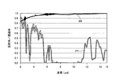
- FIG. 5 is a graph in which the reflectance of the vertically polarized electromagnetic wave and the transmittance of the parallel polarized electromagnetic wave of the reflective polarizing plate 2 are measured over the infrared band from 2 ⁇ m in the near infrared to 15 ⁇ m in the far infrared.
- the horizontal axis represents the wavelength ( ⁇ m) of electromagnetic waves.
- the vertical axis PT indicates the transmittance characteristic of the vertically polarized electromagnetic wave
- the vertical axis SR indicates the reflectance characteristic of the parallel polarized electromagnetic wave.
- the reflective polarizing plate 2 when looking at the numerical value of the characteristic PT, it has a transmittance close to 0.9 (90%) in the near infrared band close to visible light.
- the reflective polarizing plate 2 has an absorptance of about 10% with respect to electromagnetic waves in the near infrared band. More precisely, it is about 10% by adding the absorptivity and reflectance of the reflective polarizing plate 2.
- the transmittance of the vertically polarized electromagnetic wave of the reflective polarizing plate 2 gradually decreases to 60% when the wavelength is about 5 ⁇ m, for example, 30% at 6 ⁇ m, and zero at 7 ⁇ m.
- the transmittance is as high as about 90% in a wavelength band shorter than the near infrared, so that the electromagnetic wave signal intensity does not decrease.
- the transmittance is lowered, so that the electromagnetic wave signal intensity is greatly reduced.
- the measurement band of a radiation thermometer using an infrared sensor is a mid-infrared band or a far-infrared band. If the actual integration calculation is performed, when the radiation temperature is measured using the WGF in the transmission detection type, the signal component is reduced to about one-fourth of the originally obtained signal component.
- the reflectance of the reflective polarizing plate 2 with respect to the parallel polarized electromagnetic wave is a value close to 1 (for example, 98%) in both the mid-infrared band and the far-infrared band. .
- the reason why the reflectance of the reflective polarizing plate 2 with respect to the parallel polarized electromagnetic wave is close to 100% is that the reflectance of aluminum is close to 1 in the wavelength band of 4 to 15 ⁇ m. If the reflection detection type temperature measurement is possible, the signal originally obtained by the transmission detection type can be obtained almost as it is.
- the configuration that enables this reflection detection type temperature measurement is the radiation temperature measuring device 100 shown in FIG. 1, and the specific arrangement of the devices including the components of the radiation temperature measuring device 100 is the arrangement shown in FIG. is there.
- the first advantage is that the polarizing film (including WGF) has a unique rotation axis that does not change the direction of the reflected polarized wave even if the film is rotated.
- FIG. 2 illustrates the case where the infrared sensor 1 and the reflective polarizing plate 2 form an angle of 45 degrees.
- the reflection detection type can be used at angles other than 45 degrees as described above. Temperature measurement is possible.
- the reflectivity of grid-shaped aluminum with respect to parallel polarized electromagnetic waves is almost independent of the reflection angle, as in a general aluminum flat film (so-called solid film).
- the signal component input to the infrared sensor 1 is not changed at 45 degrees, 10 degrees, or 80 degrees with respect to the reflective polarizing plate 2. From this, it is understood that the polarized wave component not including the reflection of the radiation temperature measurement object may be measured by the infrared sensor 1 by the reflection of the parallel polarized electromagnetic wave.
- the second advantage is that if the rotation angle of this polarizing film is optimally selected, the reflectance of polarized electromagnetic waves perpendicular to the parallel polarized electromagnetic waves can be kept extremely small. Since the reflectivity of the parallel polarized electromagnetic wave is a signal for measurement, it is preferable that the reflectivity be large. Specifically, the following may be performed.
- FIG. 6 is a diagram more specifically showing the arrangement relationship between the reflective polarizing plate 2 and the temperature measurement object 101 shown in FIG.
- FIG. 6 shows the positional relationship between the orientation of the film surface 23 and the grid 21 of the reflective polarizing plate 2 and the temperature measurement object 101 when viewed from below in FIG. 6 is a schematic view of the state in which the WGF of FIG. 3 is first viewed from the back of the paper surface and then rotated 45 degrees clockwise from the top of the paper surface in FIG. .
- the magnitude of the signal component based on the reflectance of the reflective polarizing plate 2 with respect to the parallel polarized electromagnetic wave is as shown as the first advantage described above.
- the reflectance of the reflective polarizing plate 2 with respect to the vertically polarized electromagnetic wave only the reflected component caused by the refractive index of the WGF film substrate, that is, the film surface 23 is detected by the infrared sensor 1.
- a film substrate used for a polarizing film having WGF or a specific polarization axis is a polymer film.
- the refractive index of the polymer film is approximately 1.5.
- the signal component based on the reflectance of the vertically polarized electromagnetic wave of the reflective polarizing plate 2 is ideally zero.
- the rotation angle of the reflective polarizing plate 2 that is, the angle ⁇ shown in FIG. 2 is 45 degrees close to 56 degrees.
- the reflection angle of the polarizing film, that is, the reflective polarizing plate 2 is preferably set so that the reflectance in the vertical direction of the reflective polarizing plate 2 is minimized.
- FIG. 7 shows a specific example, in which the WGF of FIG. 3 is first viewed from the back, and then rotated 45 degrees clockwise from the left side of FIG.
- the Brewster angle is not related at all, and when the refractive index of the film surface 23 is 1.5, the reflective polarizing plate 2 has a reflectance of at least 4% with respect to the vertically polarized electromagnetic wave. Therefore, the reflectance increases as the rotation angle is increased. Therefore, not only the parallel polarized electromagnetic wave but also the signal component of the vertically polarized electromagnetic wave becomes large. For this reason, the state where the reflective polarizing plate 2 is rotated in the direction shown in FIG. 7 is not suitable for temperature measurement of the radiation temperature measuring apparatus 100 according to the present embodiment.
- the reflectance of glass is about 1.5, which is almost the same as that of a WGF substrate film.
- the reflectance when an electromagnetic wave with an incident angle of 0 to 90 degrees enters this glass is well known.
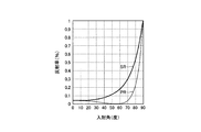
- FIG. 8 is a graph showing the reflectance when an electromagnetic wave enters the glass at an incident angle of 0 to 90 degrees.
- the horizontal axis represents the incident angle (degrees)
- the vertical axis represents the reflectance.
- the unit of reflectance is standardized by the maximum value (100%).
- the characteristic SR indicates the reflectance characteristic of the glass with respect to the S wave
- the characteristic PR indicates the reflectance characteristic of the glass with respect to the P wave.
- the P-wave reflectance of the glass decreases from about 4% (0.04) at the time of normal incidence (incidence angle 0 degree), and at the Brewster angle (about 56 degrees). Ideally zero.
- the S wave reflectance of the glass increases monotonously from 4% in the vertical direction. Therefore, the P wave of glass is acquired as a parallel polarized electromagnetic wave, and the infrared wave sensor 1 measures the P wave of glass as a signal component.
- the S wave of glass since the S wave of glass has a large reflection component by glass, it is removed as a vertically polarized electromagnetic wave. In this way, it is possible to measure the temperature without removing reflection from the glass.
- This principle is not limited to glass, but can be applied to any case in which the surface temperature of an object (including, for example, a water surface) having reflection mainly due to the refractive index is measured.
- FIG. 9 shows a specific arrangement example of the reflective polarizing plate 2 and the temperature measurement object 101 based on the above consideration.
- the arrangement example shown in FIG. 9 is a state in which the temperature measurement object 101 (glass) shown in FIG. 6 is rotated counterclockwise with respect to a direction perpendicular to the paper surface.
- the temperature measurement object 101 is glass
- the glass reflection removal effect becomes the highest when the rotation angle of the temperature measurement object 101 is 56 degrees which is a Brewster angle.
- the rotation angle is 53 degrees. Since the water surface cannot normally be rotated, in this case, the radiation temperature measuring device 100 may be rotated with respect to the water surface.
- the temperature measurement object 101 is disposed to be inclined with respect to the reflective polarizing plate 2. For this reason, when the surface of the temperature measurement object 101 is a flat surface such as glass or water, the direction detected by the infrared sensor 1 and the reflective polarizing plate 2 is different from the normal direction of the plane. That is, the direction detected by the infrared sensor 1 and the reflective polarizing plate 2 is the direction of the temperature measurement object 101.
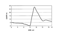
- FIG. 10 is a diagram showing the measurement results of the reflectance of the glass with respect to the electromagnetic wave in the mid-far infrared band.
- the horizontal axis represents the wavelength ( ⁇ m) of the electromagnetic wave
- the vertical axis represents the reflectance (%).
- the reflectivity of the glass with respect to electromagnetic waves in the middle and far infrared band decreases almost monotonously up to 8 ⁇ m, but increases to about 25-30% at a wavelength of about 9-10 ⁇ m.
- the detection wavelength band of the infrared sensor 1 is 8 ⁇ m or less and does not include 9 to 10 ⁇ m.
- the reflection component of the object at 50 ° C. is included in the glass at 25 ° C., the conventional band, although the glass temperature is originally 25 ° C., it is measured as about 30 ° C.
- the disturbance due to the reflectance can be removed, so the glass temperature is measured at 25 ° C. This is almost the same even when the temperature condition is changed, and in any case, the surface temperature of an object having a reflection represented by glass can be accurately measured.
- the radiation temperature measuring apparatus it is possible to detect a sufficiently large output level even in the infrared wavelength band optimum for radiation temperature measurement, and the electromagnetic wave reflected by the measurement object is infrared. Since the reflection type polarizing plate can prevent the light from entering the sensor, it is possible to prevent the temperature measurement accuracy from being lowered due to the electromagnetic wave.
Landscapes
- Physics & Mathematics (AREA)
- General Physics & Mathematics (AREA)
- Spectroscopy & Molecular Physics (AREA)
- Optics & Photonics (AREA)
- Radiation Pyrometers (AREA)
- Polarising Elements (AREA)
Abstract
本発明は、測定対象物で反射した電磁波に起因する温度の測定精度の低下を防止できる放射温度測定装置を提供すること目的とする。放射温度測定装置(100)は、測定対象の物体から放射される電磁波のうち、一方向の偏光波を反射するとともに、一方向とは垂直な方向の偏光波を透過又は吸収する反射型偏光板(2)と、反射型偏光板(2)の反射する一方向の偏光電磁波を検出する赤外線センサ(1)とを備えている。
Description
本発明は、赤外線センサを用いた放射温度測定装置に関する。
従来、赤外線センサを用いて非接触で対象物の温度を測定する温度測定装置が知られている。その応用製品例は、放射温度計(非接触温度計)、あるいはサーモグラフィ(赤外線カメラ)などである。このような温度測定装置は、対象物の放射電磁波エネルギーがその対象物の温度によってのみ決まるという原理を用いている。すなわち赤外線センサを用いれば、対象物の放射電磁波エネルギーの大部分を占める赤外線波長帯域の放射エネルギーを測定することができる。その放射エネルギーの測定値から対象物の温度を計算する。対象物の温度の計算には、たとえば黒体輻射に関するステファンボルツマンの法則などが用いられる。
しかし、黒体輻射を用いる計算は厳密には放射率が1(100%)の物体にしか適用できない。現実の対象物に放射率が1の物体は存在せず、必ずゼロでない反射率が存在する。放射温度計等の応用製品例では、対象物の反射を補正するために、一般に放射率補正と呼ばれる補正が行われている。放射率補正について具体的に数値を用いて説明すると、反射率5%の物体があったときには、放射率を95%と設定する。そうすると、元来100%測定できるはずの電磁波エネルギーが95%しか測定にかからないので、その比率の逆数を掛け算して補正する。
この方法にもまだ問題は残る。それは、実際の対象物の反射率がゼロでないため、赤外線センサ及び応用製品にその対象物の表面で反射された電磁波が届いてきてしまうことである。当然、赤外線センサはこの電磁波の反射成分も測定にかかってしまうため、この反射成分に基づく測定分が誤差となって出てきてしまう。換言すれば、前述の放射率補正は、物体で反射される元の光源が皆無(ゼロ)という条件下でしか使えない。
田村哲雄、外2名、5.5~7.9μmサーモグラフィ装置の開発とその応用、日本赤外線学会誌、日本赤外線学会編、1998年12月、8巻2号、99~107ページ
上述のように、対象物の温度を測定する際に生じる反射の問題を克服する技術が非特許文献1に記載されている。非特許文献1によれば、酸化ケイ素(SiO2)を表面主成分とするガラスやタイルなどは、8~15μm程度の波長の反射率が非常に大きい。非特許文献1には、この反射率は最大で30%程度であることが記載されている。非特許文献1には、この反射率の問題を克服するために、一般的な放射温度計やサーモグラフィの測定波長である8~15μmの赤外線を検知するのではなく、反射率の小さい5~8μm程度の波長を検知することが記載されている。
しかしながら、5~8μmの波長の赤外線に対するたとえばガラスの反射率は平均で3~4%となっている。したがって、非特許文献1に記載された技術をもってしても、反射の影響をいくらか小さくすることができるだけであり、ゼロにはできない。すなわち、電磁波の反射する成分が赤外線センサの測定に影響を及ぼす。
一方、このような界面における電磁波の反射を防止する製品としてよく知られているものに偏光板がある。この偏光板のもっとも有名な使い方は偏光サングラスであり、これにより釣り人が狙っている魚付近の水面で生じる反射光を低減させることができる。この例で見られるように、偏光板は電磁波の中でも可視光波長帯域(波長400~800nm程度)でもっともよく使われ、さらに近赤外帯域(波長800nm~1.5μm程度)でもしばしば応用される。
特許文献1には偏光板の具体的な1つの利用法が開示されている。偏光板(特許文献1の場合には偏光軸が固定されたワイヤグリッド偏光フィルム)に向けられた偏光されていない通常の光(特許文献1の場合には近赤外光線)は、その偏光板の固有の軸方向に対しては透過し、その軸方向に直交する方向に対しては反射する。その偏光透過成分及び偏光反射成分の双方の電磁波エネルギーを受光器にて測定する。しかし、特許文献1に開示された装置は、温度を測定する装置ではない。
特許文献2には、偏光板を用いつつ温度を測定する装置が開示されている。ただし、この装置は、被測定物が物理的に振動しているときに、その振動の影響を最小限にするために偏光板を用いて2つの偏光成分を測定することにより被測定物の温度を求める技術である。特許文献2には、被測定物(測定対象物)の反射率及び反射の現象自体には何の言及も示唆もない。
さらに、特許文献1及び2には記載されていない問題点について以下に示す。その問題点は、通常の偏光板は、一般的に赤外線帯域のうちの5~15μm程度の波長の電磁波をすべて透過させるように製作することが非常に困難なことである。たとえば、液晶ディスプレー(Liquid Crystal Display:LCD)にしばしば利用される染料系の偏光板は、可視光帯域の電磁波だけを透過し、赤外線帯域の電磁波はまったく透過せず、すべて偏光板に吸収される。
また、前述のワイヤグリッド偏光フィルムは、フィルムの材質が高分子であるため、この付近の赤外線帯域では材質基板の吸収モードが現れることによって透過率が非常に小さく、透過率ゼロの波長帯域も存在する。したがって、透過率がきわめて小さいために、透過偏光の測定出力がきわめて小さくなってしまう。換言すれば、上述の偏光サングラスと同じ透過型の電磁波測定は、少なくとも放射温度を測定するような赤外線帯域での測定は困難である。
本発明の目的は、放射温度測定に最適な赤外線波長帯域でも充分に大きな出力レベルで検知することができるとともに、測定対象物の反射率が大きい物体であっても、温度の測定精度低下を防止できる放射温度測定装置を提供することにある。
上記目的を達成するために、本発明の一態様による赤外線センサを用いて物体の表面温度を非接触で測定する放射温度測定装置は、前記物体から放射される電磁波を検出する赤外線センサと、前記電磁波のうち、一方向の偏光波を反射するとともに、前記一方向とは垂直な方向の偏光波を透過又は吸収する偏光板と、を備え、前記赤外線センサが、前記偏光板の反射する一方向の偏光電磁波を検出することを特徴とする。
本発明の一態様によれば、放射温度測定に最適な赤外線波長帯域でも充分に大きな出力レベルで検知することができるとともに、測定対象物の反射率が大きい物体であっても、温度の測定精度低下を防止できる。
以下、本発明の一実施形態について図1から図10を用いて説明する。
(放射温度測定装置の構成)
図1は、本実施形態にかかる放射温度測定装置100の概略構成例を示すブロック図である。放射温度測定装置100は、赤外線センサを用いて測定対象の物体の表面温度を非接触で測定する装置である。
図1は、本実施形態にかかる放射温度測定装置100の概略構成例を示すブロック図である。放射温度測定装置100は、赤外線センサを用いて測定対象の物体の表面温度を非接触で測定する装置である。
1は赤外線センサである。この赤外線センサは、後述のように本発明においては波長帯域を従来の遠赤外帯域(8~15μm)ではなく、中赤外帯域(4~8μm)とすることが好適である。
反射型偏光板2は、反射型の偏光板である。反射型の偏光板というのは、電磁波の一方が反射される作用を持つ偏光板のことである。一般の偏光板は、偏光電磁波の分離に透過又は吸収する作用を持っているが、反射する作用を持っているとは限らない。反射される作用を持たないものの一例としては液晶ディスプレーにしばしば用いられるヨウ素型の偏光板が挙げられる。一方、反射される作用を持つ偏光板としては、ワイヤグリッド偏光フィルム(以下、「WGF」と略記する)や積層型偏光フィルムが挙げられる。
放射温度測定装置100は、赤外線センサ1および反射型偏光板2を一体化した筐体3を備えている。筐体3は主に、赤外線センサ1と反射型偏光板2とを規定の寸法で組み合わせるという第1の役目と、赤外線センサ1に入り込む外乱(迷光)を筐体3の赤外吸収作用により抑えるという第2の役目とを担っている。
放射温度測定装置100は、さらに赤外線センサ1の検出信号を温度に変換する温度変換部4を備えている。温度変換部4は、図1に示すように筐体3の外部に設けられていてもよいし、筐体3の内部に設けられていてもよい。
温度測定対象物101は、放射温度測定装置100によって温度が測定される温度測定対象物であり、放射温度測定装置100とは異なる場所に配置される。また、温度測定対象物101は、基本的に何であってもよく、たとえば黒体でもよい。本実施形態による放射温度測定装置100は、温度測定対象物101がガラスなどの反射率の高い物体であればあるほど効能を発揮する。
図2は、赤外線センサ1、反射型偏光板2、筐体3及び温度測定対象物101の実際の配置関係を模式的に示す図である。図2では、赤外線センサ1、反射型偏光板2、筐体3及び温度測定対象物101の断面が模式的に示されている。赤外線センサ1及び反射型偏光板2は、互いにθの角度(本例ではθ=45度)をなして筐体3に取り付けられている。さらに、反射型偏光板2に対してθの角度(本例ではθ=45度)をなした方向に温度測定対象物101が配置されている。赤外線センサ1が測定する電磁波は、温度測定対象物101が配置されている方向から入力される。図2に示す赤外線センサ1、反射型偏光板2及び筐体3が放射温度測定装置100のハードウェア部分である。一方、図2では図示していない温度変換部4は、放射温度測定装置100の内部にあるソフトウェアで実現される。
図2では、赤外線センサ1と反射型偏光板2とのなす角度θが45度、及び反射型偏光板2と温度測定対象物101とのなす角度θが45度の角度である場合を例示している。しかしながら、反射電磁波を測定するという要請からすれば、これらの構成物のなす角度は、0度や90度に近い角度でない限り、原理的には何度でも可能である。詳細は以下で説明する。
次に、反射型偏光板2の詳細について図3及び図4を用いて説明する。図4は、図3中に示すA-A線で切断した反射型偏光板2の切断面を示している。
反射型偏光板2の具体的な一例として、WGFが挙げられる。図3に示すように、反射型偏光板2は、フィルム面23、およびフィルム面23に垂直な向きから見ると、図3のようにグリッド21(アルミニウムの細線)が一方向に並んで(図3の場合にはたてに並んで)形成されている。
反射型偏光板2の具体的な一例として、WGFが挙げられる。図3に示すように、反射型偏光板2は、フィルム面23、およびフィルム面23に垂直な向きから見ると、図3のようにグリッド21(アルミニウムの細線)が一方向に並んで(図3の場合にはたてに並んで)形成されている。
図4に示すように、反射型偏光板2には、グリッド21の方向に平行な平行偏光電磁波SWin(図4中の左側参照)と、グリッド21の方向に垂直な方向の垂直偏光電磁波PWin(図4中の右側参照)とが入射した場合、図4中の左側に示すように、もしグリッド21側から平行偏光電磁波SWinが反射型偏光板2に入射したとすれば、平行偏光電磁波SWoutは図のように反射する。一方、図4中の右側に示すように、もしグリッド21側から垂直偏光電磁波PWinが反射型偏光板2に入射したとすれば垂直偏光電磁波PWoutは図のように透過するのが一般的である。
しかしながら、実際の垂直偏光電磁波は、図4に示すような透過する成分だけではなく、反射型偏光板2のフィルム面23で吸収される成分も持ち合わせている。その具体的な数値例を図5に示す。
図5は、赤外線帯域として近赤外の2μmから遠赤外の15μmまでに渡って、反射型偏光板2の垂直偏光電磁波の反射率と平行偏光電磁波の透過率を測定したグラフである。図5において、横軸は電磁波の波長(μm)である。一方、縦軸のPTは垂直偏光電磁波の透過率特性を示し、縦軸のSRは、平行偏光電磁波の反射率特性を示している。
図5に示すように、特性PTの数値を見ると、可視光に近い近赤外帯域では0.9(90%)に近い透過率を持っている。これは、反射型偏光板2は、近赤外帯域の電磁波に対して吸収率が10%程度だということである。より正確には、反射型偏光板2の吸収率と反射率を足して10%程度である。
しかし、図5中の特性PTで示すように、反射型偏光板2の垂直偏光電磁波は、波長がたとえば5μmくらいになると透過率は60%、6μmでは30%と徐々に低下し、7μmではゼロになってしまう。つまり、WGF又は偏光板を透過検知型で使用する場合、近赤外より短い波長帯域では透過率が90%程度と高いため、電磁波信号強度が減少することはない。しかしながら、中赤外(4~8μm)又は遠赤外(8~15μm)では透過率が低下するため、電磁波信号強度が大幅に減少する。赤外線センサを用いた放射温度計の測定帯域は、中赤外帯域や遠赤外帯域である。実際の積分計算を施せば、WGFを透過検知型で使用して放射温度を測定すると、本来得られる信号成分の4分の1程度まで減少する。
一方、図5中の特性SRで示すように、平行偏光電磁波に対する反射型偏光板2の反射率は、中赤外帯域及び遠赤外帯域ともにほぼ1に近い値(たとえば98%など)となる。平行偏光電磁波に対する反射型偏光板2の反射率が100%に近い値となるのは、アルミニウムの反射率が4~15μmの波長帯域で1に近い値であることに起因する。反射検知型の温度測定が可能ならば、透過検知型の本来得られる信号がほぼそのまま得られることになる。実際に、この反射検知型温度測定を可能とする構成が図1に示す放射温度測定装置100であり、放射温度測定装置100の構成要素を含む具体的な装置の配置が図2に示す配置である。
続いて、反射型偏光板2として、WGFに代表される偏光フィルムを用いることの利点を2点に分けて説明する。
まず1点目の利点は、偏光フィルム(WGF含む)には、フィルムを回転させても反射偏光波の方向が変わらない固有の回転軸が存在することである。図2では、赤外線センサ1と反射型偏光板2が45度の角度をなした場合を例示したが、この固有の回転軸があるからこそ、上述の通り45度以外の角度でも反射検知型の温度測定が可能となる。たとえば、平行偏光電磁波に対するグリッド形状のアルミニウムの反射率は、一般のアルミニウムの平坦な膜(いわゆるべた膜)と同様に、反射角度にはほとんど依存しない。このため、反射型偏光板2に対して45度でも10度でも80度でも赤外線センサ1に入力される信号成分は変わらない。このことから、放射温度測定対象物の反射を含まない偏光波成分を平行偏光電磁波の反射によって赤外線センサ1で測定すればよいことがわかる。
仮にWGFなどの偏光フィルムの代わりにガラスそのものを用いても、本実施形態と同様の反射による温度測定が不可能なわけではない。しかし、ガラスのS波の反射率はWGFの平行偏光電磁波の反射率よりもきわめて小さく、たとえば10分の1程度である。このため、赤外線センサに入力される信号成分は格段に落ちる。
2点目の利点は、この偏光フィルムの回転角度を最適に選べば、前記平行偏光電磁波と垂直な偏光電磁波の反射率をきわめて小さく抑えることができることである。前記平行偏光電磁波の反射率は測定にかかる信号なので大きいほうがよい。具体的には、以下のようにすればよい。
図6は、図2に示す反射型偏光板2及び温度測定対象物101の配置関係をより具体的に示す図である。図6には、図2において紙面の下方向から見た場合の、反射型偏光板2のフィルム面23及びグリッド21の向きと、温度測定対象物101との位置関係が示されている。また、図6に示す反射型偏光板2は、図3のWGFをまず紙面のウラから見て、次に図6において紙面の上方向から時計回りに45度回転させた状態の模式図である。
このとき、平行偏光電磁波に対する反射型偏光板2の反射率に基づく信号成分の大きさについては、上述の1点目の利点として示した通りである。一方、垂直偏光電磁波に対する反射型偏光板2の反射率について考察すると、垂直偏光電磁波は、WGFのフィルム基材、すなわちフィルム面23の屈折率に起因する反射成分のみが赤外線センサ1で検知される信号成分として測定される。一般に、WGFや固有の偏光軸を持つ偏光フィルムに用いられるフィルム基材は、高分子フィルムである。高分子フィルムの屈折率はおよそ1.5である。したがって、高分子フィルムの屈折率に基づくブリュースター角(およそ56度)を回転角に選べば、理想的には反射型偏光板2の垂直偏光電磁波の反射率に基づく信号成分はゼロとなる。実際には、反射型偏光板2の回転角(すなわち図2に示す角度θ)を56度に近い45度にしてもほぼ同様の効果が得られる。このように、偏光フィルム、すなわち反射型偏光板2の反射角度は、反射型偏光板2の垂直な方向の反射率が最小になるように設定するのが良い。
しかし一方、図7に示すように、図6と同様の回転と異なる方向に回転させた状態も考えられる。図7はその具体例であり、図3のWGFをまずウラから見て、次に図7において紙面の左方向から時計回りに45度回転させる場合である。この場合には、ブリュースター角などはまったく関係なく、フィルム面23の屈折率を1.5とすると、反射型偏光板2は、垂直偏光電磁波に対して最低でも4%の反射率を持ってしまい、回転角度を大きくするにしたがって反射率が増大する。したがって、平行偏光電磁波だけでなく垂直偏光電磁波の信号成分も大きくなってしまう。このため、図7に示す方向に反射型偏光板2を回転させた状態は、本実施形態による放射温度測定装置100の温度測定にはどちらかと言えば適さない。
次に、本発明の温度測定対象物の具体例として、ガラスのときの状況と効果について説明する。
ガラスの反射率は、WGFの基材フィルムなどとほぼ同様の1.5程度である。このガラスに入射角度0~90度の電磁波が入ったときの反射率はよく知られている。図8は、ガラスに入射角度0~90度で電磁波が入ったときの反射率を示すグラフである。図8において、横軸は入射角(度)を示し、縦軸は反射率を示している。反射率の単位は、最大値(100%)で規格化されている。特性SRは、ガラスのS波に対する反射率特性を示し、特性PRは、ガラスのP波に対する反射率特性を示している。
ガラスの反射率は、WGFの基材フィルムなどとほぼ同様の1.5程度である。このガラスに入射角度0~90度の電磁波が入ったときの反射率はよく知られている。図8は、ガラスに入射角度0~90度で電磁波が入ったときの反射率を示すグラフである。図8において、横軸は入射角(度)を示し、縦軸は反射率を示している。反射率の単位は、最大値(100%)で規格化されている。特性SRは、ガラスのS波に対する反射率特性を示し、特性PRは、ガラスのP波に対する反射率特性を示している。
図8中の特性PRで示すように、ガラスのP波の反射率は垂直入射時(入射角0度)の4%(0.04)程度から減少し、ブリュースター角(56度程度)で理想的にはゼロとなる。一方、図8中の特性SRで示すように、ガラスのS波の反射率は垂直の4%から単調に増加する。したがって、平行偏光電磁波としてガラスのP波を取得し、ガラスのP波を信号成分として赤外線センサ1で測定する。一方、ガラスのS波はガラスによる反射成分が大きいので、垂直偏光電磁波として除去する。このようにして、ガラスでの反射を除去した温度測定が可能となる。この原理は、ガラスに限ったものではなく、主に屈折率に起因する反射を有する物体(たとえば水面なども含む)の表面温度を測定するあらゆる場合に適用できる。
図9は、以上の考察に基づく反射型偏光板2及び温度測定対象物101の具体的な配置例を示している。図9に示す配置例は、図6に示す温度測定対象物101(ガラス)を紙面に垂直な方向に対して反時計回りに回転させた状態である。温度測定対象物101がガラスの場合、温度測定対象物101の回転角度は、ブリュースター角である56度であるとガラス反射の除去効果が最も高くなる。ガラス以外の温度測定対象物として、たとえば水面であれば、回転角度は53度となる。水面は通常回転させることは不可能であるため、この場合は放射温度測定装置100を水面に対して回転させればよい。このように、温度測定対象物101は、反射型偏光板2に対して傾けられて配置される。このため、温度測定対象物101の表面がガラスや水面のように平面である場合、赤外線センサ1と反射型偏光板2により検出される方向が当該平面の法線方向と異なる。つまり、赤外線センサ1と反射型偏光板2により検出される方向は、温度測定対象物101の方向である。
最後に、ガラスを温度測定対象物101とした場合に、赤外線センサ1の検出波長帯域の設定方法について説明する。
ガラスの反射率は、可視光では上述の通りだが、仮に入射角を0度付近に固定したとしても4μm以上の中遠赤外帯域では可視光の数値から大きく変化する。図10は、中遠赤外帯域の電磁波に対するガラスの反射率の測定結果を示す図である。図10において、横軸は電磁波の波長(μm)を表し、縦軸は反射率(%)を表している。
図10に示すように、中遠赤外帯域の電磁波に対するガラスの反射率は、8μmまではほぼ単調に減少するが、9~10μm程度の波長では25~30%程度まで増加する。このため、非特許文献1の記載事項とほぼ同様に、従来の放射温度計の波長測定帯域(8~15μm)では、放射率補正を施したとしてもこの反射率に起因する外乱成分が無視できないほど大きくなる。このため、赤外線センサ1の検出波長帯域は、8μm以下であり、9~10μmを含まない。
具体的に、図10に示す反射率の測定結果を用いて計算及び実験を行うと、仮に25℃のガラスに50℃の物体の反射成分が含まれているとき、従来の帯域であると、ガラスの温度は、本来25℃であるにもかかわらず、30℃程度として測定されてしまう。
一方、反射型偏光板2を用いた本実施形態における方式を適用すれば、反射率に起因する外乱を除去できるので、ガラスの温度は25℃として測定される。これは温度条件を変えてもほぼ同様であり、どのような場合であってもガラスに代表される反射を有する物体の表面温度を正確に測定することができるようになる。
以上説明したように、本実施形態による放射温度測定装置によれば、放射温度測定に最適な赤外線波長帯域でも充分に大きな出力レベルで検知することができるとともに、測定対象物で反射した電磁波が赤外線センサに入射するのを反射型偏光板で防止できるので、この電磁波に起因する温度の測定精度の低下を防止できる。
1 赤外線センサ
2 反射型偏光板
3 筐体
4 温度変換部
21 グリッド
23 フィルム面
100 放射温度測定装置
101 温度測定対象物
2 反射型偏光板
3 筐体
4 温度変換部
21 グリッド
23 フィルム面
100 放射温度測定装置
101 温度測定対象物
Claims (9)
- 赤外線センサを用いて物体の表面温度を非接触で測定する放射温度測定装置において、
前記物体から放射される電磁波を検出する赤外線センサと
前記電磁波のうち、一方向の偏光波を反射するとともに、前記一方向とは垂直な方向の偏光波を透過又は吸収する偏光板と、
を備え、
前記赤外線センサが、前記偏光板の反射する一方向の偏光電磁波を検出すること
を特徴とする放射温度測定装置。 - 前記偏光板がフィルム形状であるとともに、前記偏光板が前記偏光板を回転させても反射偏光波の方向が変わらない軸を持つことを特徴とする請求項1に記載の放射温度測定装置。
- 前記偏光板が、前記偏光板の反射偏光波方向を回転軸として回転させた向きであることを特徴とする請求項1または2に記載の放射温度測定装置。
- 前記偏光板の反射角度は、前記偏光板の垂直な方向の反射率が最小になるように設定されていることを特徴とする請求項3記載の放射温度測定装置。
- 前記偏光板の偏光反射率は、90%以上であることを特徴とする
請求項3又は4に記載の放射温度測定装置。 - 前記偏光板は、ワイヤグリッド偏光板を含むことを特徴とする
請求項3から5までのいずれか一項に記載の放射温度測定装置。 - 前記赤外線センサの温度測定対象が、酸化ケイ素を主成分として含むことを特徴とする
請求項1から6までのいずれか一項に記載の放射温度測定装置。 - 前記物体の表面は平面であり、
前記赤外線センサと偏光板により検出される方向が前記平面の法線方向と異なることを特徴とする
請求項1から7までのいずれか一項に記載の放射温度測定装置。 - 前記赤外線センサの検出波長帯域は、8μm以下であることを特徴とする
請求項7又は8に記載の放射温度測定装置。
Priority Applications (5)
| Application Number | Priority Date | Filing Date | Title |
|---|---|---|---|
| JP2018554988A JP7004420B2 (ja) | 2016-12-07 | 2017-12-04 | 放射温度測定装置 |
| US16/467,651 US11573128B2 (en) | 2016-12-07 | 2017-12-04 | Radiation temperature measuring device |
| CN202111549318.1A CN114414058A (zh) | 2016-12-07 | 2017-12-04 | 辐射温度测定装置 |
| CN201780075144.5A CN110036265A (zh) | 2016-12-07 | 2017-12-04 | 辐射温度测定装置 |
| EP17879403.8A EP3553479A4 (en) | 2016-12-07 | 2017-12-04 | RADIATION TEMPERATURE MEASURING DEVICE |
Applications Claiming Priority (2)
| Application Number | Priority Date | Filing Date | Title |
|---|---|---|---|
| JP2016237745 | 2016-12-07 | ||
| JP2016-237745 | 2016-12-07 |
Publications (1)
| Publication Number | Publication Date |
|---|---|
| WO2018105551A1 true WO2018105551A1 (ja) | 2018-06-14 |
Family
ID=62491515
Family Applications (1)
| Application Number | Title | Priority Date | Filing Date |
|---|---|---|---|
| PCT/JP2017/043454 Ceased WO2018105551A1 (ja) | 2016-12-07 | 2017-12-04 | 放射温度測定装置 |
Country Status (5)
| Country | Link |
|---|---|
| US (1) | US11573128B2 (ja) |
| EP (1) | EP3553479A4 (ja) |
| JP (2) | JP7004420B2 (ja) |
| CN (2) | CN110036265A (ja) |
| WO (1) | WO2018105551A1 (ja) |
Cited By (2)
| Publication number | Priority date | Publication date | Assignee | Title |
|---|---|---|---|---|
| WO2020105344A1 (ja) * | 2018-11-22 | 2020-05-28 | 日本電気硝子株式会社 | ガラス物品の温度測定方法 |
| CN115655477A (zh) * | 2022-11-02 | 2023-01-31 | 南方电网数字电网研究院有限公司 | 一种基于二维光栅结构的温度检测方法 |
Families Citing this family (2)
| Publication number | Priority date | Publication date | Assignee | Title |
|---|---|---|---|---|
| CN111464730B (zh) * | 2020-05-15 | 2025-06-27 | 广东中科瑞泰智能科技有限公司 | 一种双红外偏振图像采集设备和方法 |
| CN116642596B (zh) * | 2023-04-10 | 2025-12-05 | 北京理工大学 | 基于偏振片反射偏振特性的红外分焦平面偏振校正方法 |
Citations (11)
| Publication number | Priority date | Publication date | Assignee | Title |
|---|---|---|---|---|
| US4257106A (en) * | 1979-05-24 | 1981-03-17 | Norlin Industries, Inc. | Method and apparatus for thermal imaging |
| JPS57161625A (en) * | 1981-03-31 | 1982-10-05 | Jeol Ltd | Infrared temperature measuring method |
| JPS6049850B2 (ja) * | 1980-09-29 | 1985-11-05 | 三菱電機株式会社 | 放射温度計 |
| JPS6112212B2 (ja) * | 1980-10-08 | 1986-04-07 | Mitsubishi Electric Corp | |
| JPS62266424A (ja) * | 1986-05-14 | 1987-11-19 | Nec Corp | 放射温度測定装置 |
| JP2007256219A (ja) * | 2006-03-27 | 2007-10-04 | Nissan Motor Co Ltd | 温度検出装置 |
| JP2008541133A (ja) * | 2005-05-16 | 2008-11-20 | ウルトラテック インク | 鏡面の遠隔温度測定方法及び装置 |
| JP2011007730A (ja) | 2009-06-29 | 2011-01-13 | Kobe Steel Ltd | 放射による温度測定方法及び温度測定装置 |
| JP2014134630A (ja) | 2013-01-09 | 2014-07-24 | Asahi Kasei E-Materials Corp | 光学システム |
| JP2016038537A (ja) * | 2014-08-11 | 2016-03-22 | 旭硝子株式会社 | ワイヤグリッド型偏光子、光源モジュールおよび投射型表示装置 |
| JP6019508B1 (ja) * | 2016-02-09 | 2016-11-02 | 大学共同利用機関法人 高エネルギー加速器研究機構 | 放射測定器 |
Family Cites Families (11)
| Publication number | Priority date | Publication date | Assignee | Title |
|---|---|---|---|---|
| JPS6019508B2 (ja) | 1977-02-04 | 1985-05-16 | 株式会社リコー | 静電潜像の現像方法 |
| JPH05273045A (ja) | 1992-03-26 | 1993-10-22 | Nippon Steel Corp | 透明性薄膜に被覆された物体の温度測定装置 |
| CN1030155C (zh) * | 1992-11-28 | 1995-10-25 | 浙江大学 | 三片式高效红外偏振分束器 |
| US5436443A (en) * | 1994-07-06 | 1995-07-25 | The United States Of America As Represented By The Administrator Of The National Aeronautics And Space Administration | Polaradiometric pyrometer in which the parallel and perpendicular components of radiation reflected from an unpolarized light source are equalized with the thermal radiation emitted from a measured object to determine its true temperature |
| US6174080B1 (en) * | 1998-08-06 | 2001-01-16 | Applied Materials, Inc. | Apparatus and methods for measuring substrate temperature |
| US20070009010A1 (en) * | 2005-06-23 | 2007-01-11 | Koji Shio | Wafer temperature measuring method and apparatus |
| US20120206805A1 (en) * | 2009-08-18 | 2012-08-16 | Liquidia Technologies, Inc | Nanowire grid polarizers and methods for fabricating the same |
| JP2014044244A (ja) | 2012-08-24 | 2014-03-13 | Asahi Kasei E-Materials Corp | 映像表示装置 |
| US9605999B2 (en) | 2013-11-15 | 2017-03-28 | Marko Bosiljevac | Light sources with highly stable output intensity |
| CN104390148A (zh) | 2014-10-12 | 2015-03-04 | 杨毅 | 偏振发光装置 |
| CN105890777B (zh) * | 2016-03-31 | 2018-11-06 | 北京理工大学 | 红外可控部分偏振辐射源 |
-
2017
- 2017-12-04 EP EP17879403.8A patent/EP3553479A4/en not_active Withdrawn
- 2017-12-04 CN CN201780075144.5A patent/CN110036265A/zh active Pending
- 2017-12-04 WO PCT/JP2017/043454 patent/WO2018105551A1/ja not_active Ceased
- 2017-12-04 JP JP2018554988A patent/JP7004420B2/ja active Active
- 2017-12-04 US US16/467,651 patent/US11573128B2/en active Active
- 2017-12-04 CN CN202111549318.1A patent/CN114414058A/zh not_active Withdrawn
-
2021
- 2021-06-16 JP JP2021100380A patent/JP7319325B2/ja active Active
Patent Citations (11)
| Publication number | Priority date | Publication date | Assignee | Title |
|---|---|---|---|---|
| US4257106A (en) * | 1979-05-24 | 1981-03-17 | Norlin Industries, Inc. | Method and apparatus for thermal imaging |
| JPS6049850B2 (ja) * | 1980-09-29 | 1985-11-05 | 三菱電機株式会社 | 放射温度計 |
| JPS6112212B2 (ja) * | 1980-10-08 | 1986-04-07 | Mitsubishi Electric Corp | |
| JPS57161625A (en) * | 1981-03-31 | 1982-10-05 | Jeol Ltd | Infrared temperature measuring method |
| JPS62266424A (ja) * | 1986-05-14 | 1987-11-19 | Nec Corp | 放射温度測定装置 |
| JP2008541133A (ja) * | 2005-05-16 | 2008-11-20 | ウルトラテック インク | 鏡面の遠隔温度測定方法及び装置 |
| JP2007256219A (ja) * | 2006-03-27 | 2007-10-04 | Nissan Motor Co Ltd | 温度検出装置 |
| JP2011007730A (ja) | 2009-06-29 | 2011-01-13 | Kobe Steel Ltd | 放射による温度測定方法及び温度測定装置 |
| JP2014134630A (ja) | 2013-01-09 | 2014-07-24 | Asahi Kasei E-Materials Corp | 光学システム |
| JP2016038537A (ja) * | 2014-08-11 | 2016-03-22 | 旭硝子株式会社 | ワイヤグリッド型偏光子、光源モジュールおよび投射型表示装置 |
| JP6019508B1 (ja) * | 2016-02-09 | 2016-11-02 | 大学共同利用機関法人 高エネルギー加速器研究機構 | 放射測定器 |
Non-Patent Citations (2)
| Title |
|---|
| See also references of EP3553479A4 |
| TETSUO TAMURA: "Journal of the Japan Society of Infrared Science and Technology", vol. 8, December 1998, article "5.5 - 7. 9 µm Infrared Imager and Application", pages: 99 - 107 |
Cited By (3)
| Publication number | Priority date | Publication date | Assignee | Title |
|---|---|---|---|---|
| WO2020105344A1 (ja) * | 2018-11-22 | 2020-05-28 | 日本電気硝子株式会社 | ガラス物品の温度測定方法 |
| JPWO2020105344A1 (ja) * | 2018-11-22 | 2021-10-07 | 日本電気硝子株式会社 | ガラス物品の温度測定方法 |
| CN115655477A (zh) * | 2022-11-02 | 2023-01-31 | 南方电网数字电网研究院有限公司 | 一种基于二维光栅结构的温度检测方法 |
Also Published As
| Publication number | Publication date |
|---|---|
| CN110036265A (zh) | 2019-07-19 |
| JP2021139917A (ja) | 2021-09-16 |
| JP7319325B2 (ja) | 2023-08-01 |
| JP7004420B2 (ja) | 2022-01-21 |
| CN114414058A (zh) | 2022-04-29 |
| JPWO2018105551A1 (ja) | 2019-06-24 |
| US20200080897A1 (en) | 2020-03-12 |
| EP3553479A4 (en) | 2019-12-04 |
| EP3553479A1 (en) | 2019-10-16 |
| US11573128B2 (en) | 2023-02-07 |
Similar Documents
| Publication | Publication Date | Title |
|---|---|---|
| JP7319325B2 (ja) | 放射温度測定装置 | |
| US9684203B2 (en) | Wire grid polarizer with dual absorptive regions | |
| KR101949109B1 (ko) | 재구성가능한 분광 타원계 | |
| US20140092377A1 (en) | Systems and methods for measuring birefringence in glass and glass-ceramics | |
| CN102620907B (zh) | 一种测量光学器件相位延迟角度的方法 | |
| CN110031428B (zh) | 一种基于超表面的双通道液体折射率传感系统 | |
| JP2021139917A5 (ja) | ||
| JP5900970B2 (ja) | 表面プラズモンセンサ、及び屈折率の測定方法 | |
| CN103674892B (zh) | 一种基于全内反射偏振位相差测量来监控薄膜生长的方法 | |
| US10162091B1 (en) | Silicon film optical filtering systems and methods of fabrication | |
| CN108225742A (zh) | 一种用于退偏器性能检测的方法及装置 | |
| CN208000191U (zh) | 一种退偏器检测装置 | |
| JP2017181405A (ja) | 光学測定装置及び測定方法 | |
| US9720242B2 (en) | Laser system with partial reflector | |
| EP3120172A1 (en) | Wire grid polarizer with dual absorptive regions | |
| US7269307B2 (en) | Optical configuration for generating polarization conversion | |
| JP2009058464A (ja) | 光軸計測方法および光軸計測装置 | |
| TW201813775A (zh) | 平面研磨裝置 | |
| WO2011033616A1 (ja) | 光学素子および生体用赤外線センサ | |
| CN106154593B (zh) | 异向性量测系统、异向性量测方法及其校正方法 | |
| CN115164780B (zh) | 基于空间英伯特-费德洛夫位移的角度位移传感器及其制备方法 | |
| CN105487149B (zh) | 红外制冷探测器冷光阑的偏振型复合挡光环组及制作方法 | |
| CN205353390U (zh) | 红外制冷探测器冷光阑的偏振型复合挡光环组 | |
| JP2012037268A (ja) | 表面角度計測方法及び表面角度計測装置 | |
| Sankarasubramanian et al. | Ellipsometry of coelostat coatings using a babinet compensator: simulation of the experimental accuracy |
Legal Events
| Date | Code | Title | Description |
|---|---|---|---|
| 121 | Ep: the epo has been informed by wipo that ep was designated in this application |
Ref document number: 17879403 Country of ref document: EP Kind code of ref document: A1 |
|
| ENP | Entry into the national phase |
Ref document number: 2018554988 Country of ref document: JP Kind code of ref document: A |
|
| NENP | Non-entry into the national phase |
Ref country code: DE |
|
| ENP | Entry into the national phase |
Ref document number: 2017879403 Country of ref document: EP Effective date: 20190708 |