WO2018107961A1 - 尿素机 - Google Patents
尿素机 Download PDFInfo
- Publication number
- WO2018107961A1 WO2018107961A1 PCT/CN2017/113338 CN2017113338W WO2018107961A1 WO 2018107961 A1 WO2018107961 A1 WO 2018107961A1 CN 2017113338 W CN2017113338 W CN 2017113338W WO 2018107961 A1 WO2018107961 A1 WO 2018107961A1
- Authority
- WO
- WIPO (PCT)
- Prior art keywords
- water
- filter
- water tank
- urea
- tank
- Prior art date
- Legal status (The legal status is an assumption and is not a legal conclusion. Google has not performed a legal analysis and makes no representation as to the accuracy of the status listed.)
- Ceased
Links
Images


Classifications
-
- B—PERFORMING OPERATIONS; TRANSPORTING
- B01—PHYSICAL OR CHEMICAL PROCESSES OR APPARATUS IN GENERAL
- B01J—CHEMICAL OR PHYSICAL PROCESSES, e.g. CATALYSIS OR COLLOID CHEMISTRY; THEIR RELEVANT APPARATUS
- B01J19/00—Chemical, physical or physico-chemical processes in general; Their relevant apparatus
- B01J19/0053—Details of the reactor
- B01J19/0066—Stirrers
-
- B—PERFORMING OPERATIONS; TRANSPORTING
- B01—PHYSICAL OR CHEMICAL PROCESSES OR APPARATUS IN GENERAL
- B01D—SEPARATION
- B01D15/00—Separating processes involving the treatment of liquids with solid sorbents; Apparatus therefor
- B01D15/08—Selective adsorption, e.g. chromatography
- B01D15/10—Selective adsorption, e.g. chromatography characterised by constructional or operational features
-
- B—PERFORMING OPERATIONS; TRANSPORTING
- B01—PHYSICAL OR CHEMICAL PROCESSES OR APPARATUS IN GENERAL
- B01F—MIXING, e.g. DISSOLVING, EMULSIFYING OR DISPERSING
- B01F21/00—Dissolving
- B01F21/30—Workflow diagrams or layout of plants, e.g. flow charts; Details of workflow diagrams or layout of plants, e.g. controlling means
-
- B—PERFORMING OPERATIONS; TRANSPORTING
- B01—PHYSICAL OR CHEMICAL PROCESSES OR APPARATUS IN GENERAL
- B01F—MIXING, e.g. DISSOLVING, EMULSIFYING OR DISPERSING
- B01F35/00—Accessories for mixers; Auxiliary operations or auxiliary devices; Parts or details of general application
- B01F35/181—Preventing generation of dust or dirt; Sieves; Filters
- B01F35/187—Preventing generation of dust or dirt; Sieves; Filters using filters in mixers, e.g. during venting
-
- B—PERFORMING OPERATIONS; TRANSPORTING
- B01—PHYSICAL OR CHEMICAL PROCESSES OR APPARATUS IN GENERAL
- B01J—CHEMICAL OR PHYSICAL PROCESSES, e.g. CATALYSIS OR COLLOID CHEMISTRY; THEIR RELEVANT APPARATUS
- B01J19/00—Chemical, physical or physico-chemical processes in general; Their relevant apparatus
- B01J19/0006—Controlling or regulating processes
- B01J19/0013—Controlling the temperature of the process
-
- B—PERFORMING OPERATIONS; TRANSPORTING
- B01—PHYSICAL OR CHEMICAL PROCESSES OR APPARATUS IN GENERAL
- B01J—CHEMICAL OR PHYSICAL PROCESSES, e.g. CATALYSIS OR COLLOID CHEMISTRY; THEIR RELEVANT APPARATUS
- B01J19/00—Chemical, physical or physico-chemical processes in general; Their relevant apparatus
- B01J19/18—Stationary reactors having moving elements inside
-
- C—CHEMISTRY; METALLURGY
- C02—TREATMENT OF WATER, WASTE WATER, SEWAGE, OR SLUDGE
- C02F—TREATMENT OF WATER, WASTE WATER, SEWAGE, OR SLUDGE
- C02F1/00—Treatment of water, waste water, or sewage
- C02F1/28—Treatment of water, waste water, or sewage by sorption
- C02F1/283—Treatment of water, waste water, or sewage by sorption using coal, charred products, or inorganic mixtures containing them
-
- C—CHEMISTRY; METALLURGY
- C07—ORGANIC CHEMISTRY
- C07C—ACYCLIC OR CARBOCYCLIC COMPOUNDS
- C07C273/00—Preparation of urea or its derivatives, i.e. compounds containing any of the groups, the nitrogen atoms not being part of nitro or nitroso groups
- C07C273/02—Preparation of urea or its derivatives, i.e. compounds containing any of the groups, the nitrogen atoms not being part of nitro or nitroso groups of urea, its salts, complexes or addition compounds
- C07C273/14—Separation; Purification; Stabilisation; Use of additives
- C07C273/16—Separation; Purification
-
- B—PERFORMING OPERATIONS; TRANSPORTING
- B01—PHYSICAL OR CHEMICAL PROCESSES OR APPARATUS IN GENERAL
- B01F—MIXING, e.g. DISSOLVING, EMULSIFYING OR DISPERSING
- B01F2101/00—Mixing characterised by the nature of the mixed materials or by the application field
- B01F2101/48—Mixing water in water-taps with other ingredients, e.g. air, detergents or disinfectants
-
- C—CHEMISTRY; METALLURGY
- C02—TREATMENT OF WATER, WASTE WATER, SEWAGE, OR SLUDGE
- C02F—TREATMENT OF WATER, WASTE WATER, SEWAGE, OR SLUDGE
- C02F2101/00—Nature of the contaminant
- C02F2101/10—Inorganic compounds
- C02F2101/20—Heavy metals or heavy metal compounds
-
- C—CHEMISTRY; METALLURGY
- C02—TREATMENT OF WATER, WASTE WATER, SEWAGE, OR SLUDGE
- C02F—TREATMENT OF WATER, WASTE WATER, SEWAGE, OR SLUDGE
- C02F2101/00—Nature of the contaminant
- C02F2101/30—Organic compounds
-
- Y—GENERAL TAGGING OF NEW TECHNOLOGICAL DEVELOPMENTS; GENERAL TAGGING OF CROSS-SECTIONAL TECHNOLOGIES SPANNING OVER SEVERAL SECTIONS OF THE IPC; TECHNICAL SUBJECTS COVERED BY FORMER USPC CROSS-REFERENCE ART COLLECTIONS [XRACs] AND DIGESTS
- Y02—TECHNOLOGIES OR APPLICATIONS FOR MITIGATION OR ADAPTATION AGAINST CLIMATE CHANGE
- Y02P—CLIMATE CHANGE MITIGATION TECHNOLOGIES IN THE PRODUCTION OR PROCESSING OF GOODS
- Y02P20/00—Technologies relating to chemical industry
- Y02P20/50—Improvements relating to the production of bulk chemicals
Definitions
- the invention relates to the technical field of urea processing equipment, in particular to a urea machine.
- the heating device in the urea machine of the prior art is generally disposed inside the stirring tank, or is disposed inside the ultrapure water tank to heat the water entering the stirring tank in the urea machine and prepare a urea solution.
- the heating method in the prior art is limited. In the case of using a large amount of urea solution, heating the water by the heating method of the prior art cannot meet the user's demand, and the production efficiency of the urea solution is lowered.
- the main object of the present invention is to provide a urea machine to solve the problem of low productivity of the urea machine in the prior art.
- a urea machine includes: a cabinet; a stirring tank disposed in the cabinet; a filtering portion disposed in the cabinet; a water tank portion, an inlet and a filtering portion of the water tank portion The outlet is connected to each other; the heating portion is disposed in the cabinet, the heating portion is in communication with the outlet of the water tank portion, and the outlet of the heating portion is in communication with the stirring tank.
- the heating portion is located on one side of at least one of the agitation tank, the filter portion, and the water tank portion.
- the heating portion is located on one side of the agitating tank, the filter portion, and the tank portion.
- the filter portion includes a filter disposed at a bottom of the cabinet, and the water inlet of the filter is in communication with an external water source, and the water outlet of the filter is in communication with the water tank portion.
- the filter comprises: a filter cartridge, wherein the water inlet of the filter cartridge communicates with an external water source, and the water outlet of the filter cartridge communicates with the water tank portion.
- the filter further comprises: an activated carbon filter, wherein the water inlet of the activated carbon filter communicates with the water outlet of the filter element filter, and the water outlet of the activated carbon filter communicates with the water tank portion.
- the filtering portion further includes: a first water pump disposed on the pipeline between the stirring tank and the water tank portion.
- the filtering portion includes a membrane layer filtering portion that is disposed on the pipeline between the agitating tank and the water tank portion and located above the first water pump.
- the water tank portion includes an intermediate water tank disposed above the stirring tank, and the water inlet of the intermediate water tank communicates with the water outlet of the filter portion, and the water outlet of the intermediate water tank communicates with the heating portion.
- the water tank portion further includes: a pure water water tank disposed above the filter portion and arranged side by side with the intermediate water tank, the water inlet of the pure water tank is connected with the water outlet of the intermediate water tank, and the water outlet of the pure water tank is connected to the heating portion .
- the filtering portion includes: a second water pump disposed on the bottom of the cabinet, and the second water pump is located on a pipeline connecting the intermediate water tank and the stirring tank.
- the urea machine comprises: a suction device, the suction device has a suction port and a discharge port, and the discharge port is connected with the stirring chamber of the agitating tank, and the suction port is used for adsorbing urea to transport the urea into the stirring chamber. .
- the suction device comprises: a casing, the first end of the casing is provided with a feeding port, the second end of the casing is provided with a discharge port, the casing further has an exhaust port, and the exhaust port is for discharging The air in the housing forms a suction port at the feed port.
- the suction device further includes: a partition plate disposed in the casing, wherein the partition plate and the side wall of the casing respectively form an intake passage and an exhaust passage, and the exhaust port communicates with the exhaust passage, and the partition plate An overflow port that communicates with the intake passage and the exhaust passage is formed between the bottom portion and the side wall of the housing.
- the partition plate includes: a first plate segment, the first plate segment is disposed in a vertical direction, the first end of the first plate segment is connected to the housing, and the inlet port and the exhaust port are located opposite to the first plate segment Two sides; a second plate segment, the second plate segment is connected to the second end of the first plate segment and has an angle, and the second plate segment is disposed away from the exhaust port.
- an angle between the second plate segment and the second end of the first plate segment is at a right angle.
- the suction device comprises: a suction portion having a suction port and an outlet, the outlet being in communication with the feed port, and the suction port forming a suction port.
- each suction device there are a plurality of suction devices, and the discharge ports of each suction device are connected to the inner cavity of the agitating tank, and the feeding port of one suction device of the two adjacent suction devices and the other suction device The exhaust ports are connected.
- the heating portion includes a heating water tank for storing and heating water from the water tank portion.
- the urea machine includes a cabinet, a stirring tank, a filtering portion, a water tank portion, and a heating portion.
- the mixing tank is placed in the cabinet.
- the filter unit is disposed in the cabinet.
- the inlet of the water tank portion is in communication with the outlet of the filter portion.
- the heating portion is disposed in the cabinet body, the heating portion is in communication with the outlet of the water tank portion, and the outlet of the heating portion is in communication with the stirring tank.
- the water in the water tank portion is heated by a separate heating portion, and then the water heated by the heating portion is sent to the stirring tank to prepare urea, so that the heating portion can timely heat the water in the water tank portion, thereby effectively improving The efficiency of the urea machine meets the needs of users.
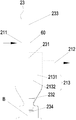
- Figure 1 is a schematic view showing the structure of a first embodiment of a suction device for a urea machine according to the present invention
- Figure 2 is a schematic view showing the structure of the second embodiment of the suction device of the urea machine of Figure 1;
- Figure 3 is a structural flow chart showing the first embodiment of the suction device of the urea machine of Figure 1;
- Figure 4 is a structural flow chart showing the second embodiment of the suction device of the urea machine of Figure 2;
- Figure 5 is a schematic view showing the structure of the urea machine of Figure 1;
- Figure 6 is a schematic view showing the structure of the first angle of view of the urea machine of Figure 5;
- Figure 7 is a schematic view showing the structure of the second angle of view of the urea machine of Figure 5;
- Fig. 8 is a view showing the structure of a third angle of view of the urea machine of Fig. 5.
- 2131 a first plate segment
- 2132 a second plate segment
- the feeding part 231, connecting rod; 232, picking plate; 233, handle; 234, retaining plate;
- filter element filter 31, filter element filter; 32, activated carbon filter; 33, the first water pump; 34, membrane filter; 35, the second pump;
- spatially relative terms such as “above”, “above”, “on top”, “above”, etc., may be used herein to describe as in the drawings.
- the exemplary term “above” can include both “over” and "under”.
- the device can also be positioned in other different ways (rotated 90 degrees or at other orientations) and the corresponding description of the space used herein is interpreted accordingly.
- the urea solution production equipment in the prior art is mainly divided into three types, one is a large-scale chemical equipment, generally used for a professional large-scale urea solution manufacturer, and the other is a small-scale equipment with low integration, which is generally composed of three More than one component, it is often necessary to splicing these components at the installation site, which brings great difficulties to the installation and commissioning of the equipment.
- a urea machine is provided.
- the urea machine includes a cabinet 10, a stirring tank 20, a filter portion 30, a water tank portion 40, and a heating portion 50.
- the agitation tank 20 is disposed in the cabinet 10.
- the filter unit 30 is disposed in the cabinet 10 .
- the inlet of the tank portion 40 is in communication with the outlet of the filter portion 30.
- the heating unit 50 is disposed in the cabinet 10, the heating unit 50 communicates with the outlet of the water tank unit 40, and the outlet of the heating unit 50 communicates with the agitation tank 20.
- the water in the water tank portion 40 is heated by a separate heating portion 50, and then the water heated by the heating portion 50 is sent to the stirring tank 20 to produce urea, so that the heating portion 50 can be set in time.
- the heating of the water in the water tank portion 40 effectively improves the efficiency of the urea machine and satisfies the user's needs.
- the heating unit 50 is located on one side of at least one of the agitating tank 20, the filter unit 30, and the tank unit 40. This arrangement can effectively reduce the processing difficulty of the casing of the urea machine, making the layout of the urea machine more reasonable and simple. Of course, as shown in FIG. 5, the heating portion 50 is located on one side of the agitating tank 20, the filter portion 30, and the tank portion 40.
- the filter unit 30 includes a filter.
- the filter is disposed at the bottom of the cabinet 10, and the water inlet of the filter communicates with an external water source, and the water outlet of the filter communicates with the water tank portion 40. This arrangement can effectively filter out impurities from the external water source, effectively improving the quality of the urea solution.
- the filter includes a filter cartridge filter 31.
- the water inlet of the filter element filter 31 communicates with an external water source, and the water outlet of the filter element filter 31 communicates with the water tank portion 40. This arrangement effectively filters out small particles of fine sand and other impurities in the water source.
- the filter further includes a water inlet of the activated carbon filter 32 communicating with the water outlet of the filter element filter 31, and a water outlet of the activated carbon filter 32 is in communication with the water tank portion 40.
- This arrangement can effectively remove small molecular organic substances and heavy metals from the water in the filter element filter 31.
- the filter portion 30 also includes a first water pump 33.
- the first water pump 33 is disposed on a line between the agitation tank 20 and the water tank portion 40.
- the filter unit 30 includes a membrane layer filter unit 34.
- the membrane layer filter portion 34 is provided on a line between the agitation tank 20 and the tank portion 40 and is located above the first water pump 33. This arrangement can further filter the external water source, effectively improve the quality of the water, thereby improving the quality of the urea solution and increasing the reliability of the urea machine.
- the water tank portion 40 includes an intermediate water tank 41.
- the intermediate tank 41 is disposed above the agitating tank 20, and the water inlet of the intermediate tank 41 communicates with the water outlet of the filter unit 30, and the water outlet of the intermediate tank 41 communicates with the heating unit 50.
- This arrangement serves to store the filtered water in the intermediate tank so that there is sufficient water for backup when large quantities of urea solution are required to be produced.
- the water tank portion 40 also includes a pure water tank 42.
- the pure water tank 42 is disposed above the filter unit 30 and arranged in parallel with the intermediate tank 41.
- the water inlet of the pure water tank 42 communicates with the water outlet of the intermediate tank 41, and the outlet of the pure water tank 42 communicates with the heating unit 50.
- This arrangement allows the pure water tank 42 to prepare pure water by using the water in the intermediate tank 41, and then inputs it into the heating unit 50 for heating. The rate of urea production by the urea machine is effectively increased.
- the water tank portion 40 also includes a liquid storage tank 43.
- the liquid storage tank 43 is disposed on the bottom of the cabinet 10, the first water pump 33 is located at one side of the liquid storage tank 43, and the liquid inlet of the liquid storage tank 43 is in communication with the liquid outlet of the stirring tank 20, and the liquid storage tank 43 is The liquid outlet is connected to the user end.
- the liquid storage tank 43 and the first water pump 33 are disposed on the bottom of the cabinet 10, such that the first water pump 33 with a heavier weight is disposed on the liquid storage tank 43 and the weight of the urea cabinet is unstable. happening. Providing the reservoir 43 at the bottom enables the urea solution prepared in the stirred tank to be stored for use.
- the filter unit 30 includes a second water pump 35.
- the second water pump 35 is disposed on the bottom of the cabinet 10, and the second water pump 35 is located on the line connecting the intermediate water tank 41 and the agitating tank 20. This arrangement can effectively ensure that there is sufficient water pressure between the pipes for water flow.
- the urea machine includes a suction device 21.
- the suction device 21 has a suction port and a discharge port, and the discharge port communicates with the agitation chamber of the agitation tank 20, and the suction port is used for adsorbing urea to transport the urea into the agitation chamber.
- the urea granules are fed by the suction device, which effectively increases the stability and reliability of the feeding of the urea granules.
- the suction device 21 includes a housing.
- the first end of the casing is provided with a feeding port 211, the second end of the casing is provided with a discharge port, and the casing further has an exhaust port 212 for exhausting air in the casing, the inlet port 211 forms a suction port.
- the suction device 21 also includes a partition 213.
- the partition plate 213 is disposed in the casing, and the exhaust passage and the exhaust passage are respectively formed between the partition plate 213 and the side wall of the casing, and the exhaust port 212 communicates with the exhaust passage, and the bottom of the partition plate 213 and the side wall of the casing
- An overflow port is formed between the intake passage and the exhaust passage.
- the partition 213 includes a first plate segment 2131 and a second plate segment 2132.
- the first plate segment 2131 is disposed in a vertical direction, the first end of the first plate segment 2131 is connected to the housing, and the inlet port 211 and the exhaust port 212 are located on opposite sides of the first plate segment 2131.
- the second plate segment 2132 is connected to the second end of the first plate segment 2131 and has an included angle, and the second plate segment 2132 is disposed away from the exhaust port 212.
- the second plate segment 2132 is connected to the second end of the first plate segment 2131 and has an included angle at an angle.
- the angle is set to a right angle, which can effectively buffer the speed at which the urea particles fall into the agitating tank, and prevent a large amount of particles from accumulating at the feeding port of the suction device at the same time to cause clogging.
- the suction device 21 in order to enable the urea particles to smoothly enter the agitation tank, the suction device 21 includes the suction portion 22.
- the suction portion 22 has a suction port and an outlet, and the outlet communicates with the feed port 211, and the suction port forms a suction port.
- the suction port is located in the container containing the urea particles, and the outlet is in communication with the feed port, so that when the motor of the suction portion 22 is opened, the urea particles can be smoothly transferred to the agitation tank.
- the suction device 21 is arranged in plurality, and the discharge ports of each suction device 21 are connected to the inner cavity of the agitating tank, and two adjacent suction devices 21 are connected.
- the feed port 211 of one of the suction devices 21 is in communication with the exhaust port 212 of the other suction device 21.
- the heating portion 50 includes a heating water tank for storing and heating water from the water tank portion 40.
- the arrangement is such that the heating water tank can store water of a certain heat temperature, and when the urea solution is prepared, the water of the water tank portion 40 is sent to the heating water tank for heating, because the heating water tank originally stores a relatively high temperature. Water that makes it come from After the water in the water tank portion 40 is mixed with the original water and heated for a short time, the water in the heating water tank can be brought to the required water temperature, and then transported to the stirring tank for the preparation of the urea solution, which can effectively shorten the preparation of urea.
- the heating time of the water required for the solution increases the suitability and reliability of the urea solution.
- the urea machine adopts a split structure, and divides the urea machine equipment into two parts: the main machine and the auxiliary machine.
- the main unit integrates ultrapure water filtration, ultrapure water storage, urea granule feeding, urea solution stirring, urea solution storage, and the auxiliary machine is air energy.
- the water heater is mainly responsible for the ultra-pure water heating.
- the main machine adopts a three-layer layout structure, and the bottom layer is arranged with pumps, finished solution storage boxes, mixing boxes, etc., which are bulky and require frequent maintenance and adjustment.
- the middle layer is equipped with RO reverse osmosis membrane, water pipe, solenoid valve, light weight pump, etc.
- the middle layer is equipped with intermediate water tank, ultra-pure water tank, EDI and other light weight materials, so that the center of gravity of the main engine is reduced as much as possible, which is convenient for equipment transportation and structural stability.
- the materials that need to be repaired, replaced, and maintained frequently are placed in a position that is easy to repair, replace, and maintain.
- the air energy water heater is used for heating, and the heat pump principle is used to absorb heat from the surrounding environment, and the heat is sent to the condenser through the compressor to release the water to the water tank to heat the water.
- the suction device includes a beating portion 23.
- the hitting portion 23 is rotatably disposed in the casing to cause the urea adhering to the casing to fall off.
- Such an arrangement can effectively prevent the urea particles from adhering to the inner wall of the casing and affect the feed rate of the urea particles, and the arrangement can ensure the stability and reliability of the feeding speed of the suction device.
- the hitting portion 23 includes a connecting rod 231 and a dip plate 232.
- the connecting rod 231 is rotatably disposed at the feeding port 211, the first end of the connecting rod 231 extends toward the inside of the casing, and the second end of the connecting rod 231 extends outside the casing.
- the dip plate 232 is connected to the first end of the connecting rod 231, and the dip plate 232 extends along the side wall of the casing.
- the connecting rod 231 drives the dip plate 232 to rotate along the circumferential direction of the casing.
- the dip plate 232 can remove the urea particles attached to the side wall of the casing during the rotation process, thereby avoiding the accumulation of urea particles on the inner wall of the casing and then affecting the stability of the urea particle feed.
- the end of the dip plate 232 is placed with a gap between the side walls of the housing.
- a T-shaped handle 233 is disposed on the second end of the connecting rod 231.
- the action of the material can be achieved by hand gripping the handle 233 and rotating the handle 233.
- the beating portion 23 includes a baffle plate 234.
- the baffle 234 is disposed within the housing and below the dip plate 232.
- the setting of the baffle plate can reduce the speed of the urea particles entering the stirring tank, and play a buffering role to prevent the amount of urea particles entering and the amount of urea particles from being too large and too fast.
- the baffle 234 also prevents the urea particles that have been located below the baffle 234 from being sucked back into the upper casing and discharged to the outside of the casing to cause waste of urea particles.
- a water inlet 214 is also formed in the casing.
- the interior of the casing can be cleaned, and the urea particles are prevented from adhering to the inner wall of the casing for a long time, which corrodes the casing and affects the service life of the casing.
- the suction device includes a feed tube section 60.
- One end of the feeding pipe section 60 is in communication with the inner cavity of the casing.
- the side wall of the feeding pipe section 60 is provided with a feeding port 211.
- the other end of the feeding pipe section 60 is a free end and is closed, and a part of the connecting rod 231 is located at the feeding pipe section. 60 and coaxial settings. This arrangement can effectively set the connecting rod 231 on the housing and achieve rotation.
- the urea machine includes a cabinet 10 and a temperature control portion 70.
- the temperature control unit 70 is disposed in the cabinet 10, and the temperature control unit 70 is configured to control the temperature in the cabinet 10 to be within a preset temperature range.
- the temperature control part is arranged inside the urea cabinet body, which can effectively control the temperature inside the cabinet to be within a certain range, thereby effectively ensuring that the temperature inside the cabinet body is always within a constant temperature range, and the storage in the cabinet body is ensured.
- the quality of the urea solution is arranged inside the urea cabinet body, which can effectively control the temperature inside the cabinet to be within a certain range, thereby effectively ensuring that the temperature inside the cabinet body is always within a constant temperature range, and the storage in the cabinet body is ensured.
- the urea machine includes a stirring tank 20 and a water tank portion 40.
- the stirring tank 20 and the water tank portion 40 are disposed in the cabinet 10, and the temperature control portion 70 is configured to control the temperature of the urea solution in the water tank portion 40 to be within a preset temperature range.
- Such an arrangement can effectively keep the temperature of the water tank disposed in the cabinet 10 constant within a certain temperature range value, effectively improving the usability of the urea machine and the reliability of preparing the urea solution.
- the water tank portion 40 includes a liquid storage tank 43.
- the liquid storage tank 43 is disposed on the bottom of the cabinet 10, and the liquid inlet of the liquid storage tank 43 communicates with the liquid outlet of the stirring tank 20, and the liquid outlet of the liquid storage tank 43 communicates with the user end, and the temperature control unit 70 It is used to control the temperature inside the reservoir 43 so that the temperature of the urea solution in the reservoir 43 is within a preset temperature range.
- This arrangement can effectively control the storage temperature of the urea solution in the reservoir 43.
- the preset temperature is t, wherein 5 ° C ⁇ t ⁇ 35 ° C. That is, the internal temperature of the cabinet 10 is controlled within this range to effectively prevent the urea solution stored in the reservoir 43 from affecting the quality of the urea solution due to excessive or too low temperature.
- the temperature control unit 70 includes a refrigeration unit 71.
- the refrigerating device 71 is disposed on the cabinet 10 to lower the temperature inside the cabinet 10.
- a cooling device 71 capable of reducing the internal temperature of the cabinet is provided on the cabinet 10.
- the refrigeration device may be an evaporator or a radiator such as a fan.
- the temperature control unit 70 further includes a heating device 72.
- the heating device 72 is disposed within the cabinet 10, and the heating device 72 is used to increase the temperature within the cabinet 10.
- Such an arrangement can effectively avoid the problem that the urea solution in the reservoir 43 is precipitated due to a too low temperature to cause a decrease in the urea solution.
- the reliability of the urea solution for preparing the urea solution is effectively improved.
- the temperature control unit 70 includes a temperature sensor and a controller that controls the temperature in the cabinet 10 based on the detection result of the temperature sensor. This arrangement can effectively increase the controllability of the internal temperature of the cabinet. At the same time, the intelligent control of the internal environment temperature control of the cabinet 10 is improved, and the sensitivity of the cabinet environment temperature control is improved.
- a plurality of heating devices 72 may be disposed inside the cabinet.
- the heating device 72 may be an electric heating tube having a heat generating function or a heat exchange coil having a heat function.
- the cabinet 10 has a door panel structure.
- the door panel structure has a door panel body, and the door panel body is provided with a foaming material. This arrangement can effectively ensure the stability of the temperature inside the cabinet 10, so that the cabinet 10 has a heat insulating effect.
- the foaming material comprises an isocyanate and a combined polyether.
- the door panel structure made of isocyanate and combined polyether has strong heat preservation effect.
- the air inside the cabinet body is prevented from exchanging heat with the outside air through the door panel structure, and a sponge and a foam rubber are disposed at the edge of the door panel body.
- a sponge and a foam rubber are disposed at the edge of the door panel body.
- it can also be one of a sponge and a foamed rubber.
- the split structure is divided into two parts: the main machine and the auxiliary machine.
- the main unit integrates ultrapure water filtration, ultrapure water storage, urea pellet loading, urea solution stirring, urea solution storage, and the auxiliary machine is an air energy water heater. Responsible for ultra-pure water heating.
- the main machine adopts a three-layer layout structure, and the bottom layer is arranged with pumps, finished solution storage boxes, mixing boxes, etc., which are bulky and require frequent maintenance and adjustment.
- the middle layer is equipped with RO reverse osmosis membrane, water pipe, solenoid valve, light weight pump, etc.
- the materials to be maintained, the middle layer is equipped with intermediate water tank, ultra-pure water tank, EDI and other light weight materials, so that the center of gravity of the main engine is reduced as much as possible, which is convenient for equipment transportation and structural stability.
- the air energy water heater is used for heating, and the heat pump principle is used to absorb heat from the surrounding environment, and the heat is sent to the condenser through the compressor to release the water to the water tank to heat the water.
- the ultrapure water is directly sent to the air energy water heater to be heated to above 35 °C.
- the air energy water heater is used for heating, and the heat pump principle is used to absorb heat from the surrounding environment, and the heat is sent to the condenser through the compressor to release the water to the water tank, heat the water, reduce the energy exchange link, and improve the heating efficiency.
- the water tank of the air energy water heater adopts foam insulation to avoid heat loss of the heated ultra pure water.
- the entire urea machine's workflow includes: water source ⁇ pretreatment (removal of particulate impurities) ⁇ two-stage reverse osmosis (primary removal of ions in water) ⁇ EDI (further removal of trace ions in water) ⁇ ultrapure water ⁇ air energy water heater ( Heat the water to above 35 °C) ⁇ stir box ⁇ finished box.
- the suction portion 22 draws urea particles from the container containing the urea particles (shown as A in Figures 3 and 4) and delivers the urea particles to the suction device 21 (shown in Figures 3 and 4, respectively).
- the two suction devices 21) are sent to the urea stirred tank through the feed port of the suction device 21 (as shown at B in Figs. 1 and 2) to prepare the urea solution.
Landscapes
- Chemical & Material Sciences (AREA)
- Organic Chemistry (AREA)
- Chemical Kinetics & Catalysis (AREA)
- Analytical Chemistry (AREA)
- Life Sciences & Earth Sciences (AREA)
- Hydrology & Water Resources (AREA)
- Engineering & Computer Science (AREA)
- Environmental & Geological Engineering (AREA)
- Water Supply & Treatment (AREA)
- Exhaust Gas After Treatment (AREA)
Abstract
一种尿素机,包括柜体(10)、搅拌罐(20)、过滤部(30)、水箱部(40)和加热部(50),搅拌罐(20)设置于柜体(10)内,过滤部(30)设置于柜体(10)内,水箱部(40)的进口与过滤部(30)的出口相连通,加热部(50)设置于柜体(10)内,加热部(50)与水箱部(40)的出口相连通,加热部(50)的出口与搅拌罐(20)相连通。采用单独的加热部(50)对水箱部(40)内的水进行加热,然后将经加热部(50)加热过的水输送至搅拌罐(20)中进行制作尿素,这样设置使得加热部(50)能够及时的对水箱部(40)内的水进行加热,有效地提高了该尿素机的效率,满足了用户需求。
Description
本发明涉及尿素加工设备技术领域,具体而言,涉及一种尿素机。
现有技术中的尿素机中的加热装置一般是设置于搅拌罐内部,或是设置于超纯水水箱内部对进入尿素机中搅拌罐的水进行加热并制备尿素溶液。现有技术中的加热方式有限,在大量使用尿素溶液的情况下,采用现有技术中的加热方式对水进行加热不能满足用户需求,降低了尿素溶液的生产效率。
发明内容
本发明的主要目的在于提供一种尿素机,以解决现有技术中的尿素机生产效率低的问题。
为了实现上述目的,根据本发明的一个方面,提供了一种尿素机,包括:柜体;搅拌罐,设置于柜体内;过滤部,设置于柜体内;水箱部,水箱部的进口与过滤部的出口相连通;加热部,设置于柜体内,加热部与水箱部的出口相连通,加热部的出口与搅拌罐相连通。
进一步地,加热部位于搅拌罐、过滤部以及水箱部中至少一个的一侧。
进一步地,加热部位于搅拌罐、过滤部以及水箱部的一侧。
进一步地,过滤部包括过滤器,过滤器设置于柜体的底部,过滤器的进水口与外界水源相连通,过滤器的出水口与水箱部相连通。
进一步地,过滤器包括:滤芯过滤器,滤芯过滤器的进水口与外界水源相连通,滤芯过滤器的出水口与水箱部相连通。
进一步地,过滤器还包括:活性炭过滤器,活性炭过滤器的进水口与滤芯过滤器的出水口相连通,活性炭过滤器的出水口与水箱部相连通。
进一步地,过滤部还包括:第一水泵,设置于搅拌罐与水箱部之间的管路上。
进一步地,过滤部包括:膜层过滤部,膜层过滤部设置于搅拌罐与水箱部之间的管路上并位于第一水泵的上方。
进一步地,水箱部包括:中间水箱,设置于搅拌罐的上方,中间水箱的进水口与过滤部的出水口相连通,中间水箱的出水口与加热部相连通。
进一步地,水箱部还包括:纯水水箱,设置于过滤部的上方并与中间水箱并排设置,纯水水箱的进水口与中间水箱的出水口相连通,纯水水箱出水口与加热部相连通。
进一步地,过滤部包括:第二水泵,设置于柜体的底部上,第二水泵位于连接中间水箱与搅拌罐之间的管路上。
进一步地,尿素机包括:吸料装置,吸料装置具有吸料口和出料口,出料口与搅拌罐的搅拌腔相连通,吸料口用于吸附尿素以将尿素输送至搅拌腔内。
进一步地,吸料装置包括:壳体,壳体的第一端设置有进料口,壳体的第二端设置有出料口,壳体上还具有排气口,排气口用于排出壳体内的空气,进料口形成吸料口。
进一步地,吸料装置还包括:隔板,隔板设置于壳体内,隔板与壳体侧壁之间分别形成进气通道和排气通道,排气口与排气通道相连通,隔板的底部与壳体的侧壁之间形成连通进气通道和排气通道的过流口。
进一步地,隔板包括:第一板段,第一板段沿竖直方向设置,第一板段的第一端与壳体相连接,进料口与排气口位于第一板段相对的两侧;第二板段,第二板段与第一板段的第二端相连接并具有夹角,第二板段远离排气口设置。
进一步地,第二板段与第一板段的第二端之间的夹角呈直角。
进一步地,吸料装置包括:抽吸部,抽吸部具有吸口和出口,出口与进料口相连通,吸口形成吸料口。
进一步地,吸料装置为多个,各吸料装置的出料口均与搅拌罐内腔相连通,相邻两个吸料装置中的一个吸料装置的进料口与另一个吸料装置的排气口相连通。
进一步地,加热部包括加热水箱,加热水箱用于储存和加热来自水箱部的水。
应用本发明的技术方案,该尿素机包括柜体、搅拌罐、过滤部、水箱部和加热部。搅拌罐设置于柜体内。过滤部设置于柜体内。水箱部的进口与过滤部的出口相连通。加热部设置于柜体内,加热部与水箱部的出口相连通,加热部的出口与搅拌罐相连通。采用单独的加热部对水箱部内的水进行加热,然后将经加热部加热过的水输送至搅拌罐中进行制作尿素,这样设置使得加热部能够及时的对水箱部内的水进行加热,有效地提高了该尿素机的效率,满足了用户需求。
构成本申请的一部分的说明书附图用来提供对本发明的进一步理解,本发明的示意性实施例及其说明用于解释本发明,并不构成对本发明的不当限定。在附图中:
图1示出了根据本发明的尿素机的吸料装置的实施例一的结构示意图;
图2示出了图1中尿素机的吸料装置的实施例二的结构示意图;
图3示出了图1中尿素机的吸料装置的实施例一的结构流程图;
图4示出了图2中尿素机的吸料装置的实施例二的结构流程图;
图5示出了图1中尿素机的结构示意图;
图6示出了图5中尿素机的第一视角的结构示意图;
图7示出了图5中尿素机的第二视角的结构示意图;以及
图8示出了图5中尿素机的第三视角的结构示意图。
其中,上述附图包括以下附图标记:
10、柜体;
20、搅拌罐;
21、吸料装置;
211、进料口;212、排气口;213、隔板;214、进水口;
2131、第一板段;2132、第二板段;
22、抽吸部;
23、打料部;231、连接杆;232、擀料板;233、手柄;234、挡料板;
30、过滤部;
31、滤芯过滤器;32、活性炭过滤器;33、第一水泵;34、膜层过滤部;35、第二水泵;
40、水箱部;41、中间水箱;42、纯水水箱;43、储液箱;
50、加热部;
60、进料管段;
70、控温部;71、制冷装置;72、加热装置。
需要说明的是,在不冲突的情况下,本申请中的实施例及实施例中的特征可以相互组合。下面将参考附图并结合实施例来详细说明本发明。
需要注意的是,这里所使用的术语仅是为了描述具体实施方式,而非意图限制根据本申请的示例性实施方式。如在这里所使用的,除非上下文另外明确指出,否则单数形式也意图包括复数形式,此外,还应当理解的是,当在本说明书中使用术语“包含”和/或“包括”时,其指明存在特征、步骤、操作、器件、组件和/或它们的组合。
需要说明的是,本申请的说明书和权利要求书及上述附图中的术语“第一”、“第二”等
是用于区别类似的对象,而不必用于描述特定的顺序或先后次序。应该理解这样使用的术语在适当情况下可以互换,以便这里描述的本申请的实施方式例如能够以除了在这里图示或描述的那些以外的顺序实施。此外,术语“包括”和“具有”以及他们的任何变形,意图在于覆盖不排他的包含,例如,包含了一系列步骤或单元的过程、方法、系统、产品或设备不必限于清楚地列出的那些步骤或单元,而是可包括没有清楚地列出的或对于这些过程、方法、产品或设备固有的其它步骤或单元。
为了便于描述,在这里可以使用空间相对术语,如“在……之上”、“在……上方”、“在……上表面”、“上面的”等,用来描述如在图中所示的一个器件或特征与其他器件或特征的空间位置关系。应当理解的是,空间相对术语旨在包含除了器件在图中所描述的方位之外的在使用或操作中的不同方位。例如,如果附图中的器件被倒置,则描述为“在其他器件或构造上方”或“在其他器件或构造之上”的器件之后将被定位为“在其他器件或构造下方”或“在其他器件或构造之下”。因而,示例性术语“在……上方”可以包括“在……上方”和“在……下方”两种方位。该器件也可以其他不同方式定位(旋转90度或处于其他方位),并且对这里所使用的空间相对描述作出相应解释。
现在,将参照附图更详细地描述根据本申请的示例性实施方式。然而,这些示例性实施方式可以由多种不同的形式来实施,并且不应当被解释为只限于这里所阐述的实施方式。应当理解的是,提供这些实施方式是为了使得本申请的公开彻底且完整,并且将这些示例性实施方式的构思充分传达给本领域普通技术人员,在附图中,为了清楚起见,有可能扩大了层和区域的厚度,并且使用相同的附图标记表示相同的器件,因而将省略对它们的描述。
现有技术中的尿素溶液生产设备主要分为三种,一种是大型化工设备,一般用于专业的大型尿素溶液生产厂家,一种为集成度不高的小型设备,这种设备一般由三个以上部件组成,往往需要在安装现场将这些部件拼接,这给设备的安装调试带来了极大的困难。还有一种则是高度集成化的尿素溶液生产设备,设备中集成了净水、空气能加热、搅拌、溶液存储、上料等多个模块,这种设备虽然集成度很高,但这种设备体积较大,不便于运输,设备内部管路布置复杂不便于批量生产。
结合图1至图8所示,根据本发明的实施例,提供了一种尿素机。
具体地,该尿素机包括柜体10、搅拌罐20、过滤部30、水箱部40和加热部50。搅拌罐20设置于柜体10内。过滤部30设置于柜体10内。水箱部40的进口与过滤部30的出口相连通。加热部50设置于柜体10内,加热部50与水箱部40的出口相连通,加热部50的出口与搅拌罐20相连通。
在本实施例中,采用单独的加热部50对水箱部40内的水进行加热,然后将经加热部50加热过的水输送至搅拌罐20中进行制作尿素,这样设置使得加热部50能够及时的对水箱部40内的水进行加热,有效地提高了该尿素机的效率,满足了用户需求。
其中,加热部50位于搅拌罐20、过滤部30以及水箱部40中至少一个的一侧。这样设置能够有效地降低尿素机的壳体的加工难度,使得尿素机的布局更加合理简单。当然,如图5所示,加热部50均位于搅拌罐20、过滤部30以及水箱部40的一侧。
其中,过滤部30包括过滤器。过滤器设置于柜体10的底部,过滤器的进水口与外界水源相连通,过滤器的出水口与水箱部40相连通。这样设置能够有效地将来自外界水源中的杂质过滤掉,有效地提高了尿素溶液的质量。
进一步地,过滤器包括滤芯过滤器31。滤芯过滤器31的进水口与外界水源相连通,滤芯过滤器31的出水口与水箱部40相连通。这样设置能够有效地过滤掉水源中的小颗粒细沙和其他杂质。
为了进一步地提高过滤器的过滤性能,过滤器还包括活性炭过滤器32的进水口与滤芯过滤器31的出水口相连通,活性炭过滤器32的出水口与水箱部40相连通。这样设置能够有效地去处来自滤芯过滤器31中水中的小分子有机物以及重金属。
为了保证整个水循环中具有足够的水压力,过滤部30还包括第一水泵33。第一水泵33设置于搅拌罐20与水箱部40之间的管路上。
过滤部30包括膜层过滤部34。膜层过滤部34设置于搅拌罐20与水箱部40之间的管路上并位于第一水泵33的上方。这样设置能够进一步地起到对外界水源的过滤作用,有效提高了水的质量,进而提高了尿素溶液的质量,增加了尿素机的可靠性。
水箱部40包括中间水箱41。中间水箱41设置于搅拌罐20的上方,中间水箱41的进水口与过滤部30的出水口相连通,中间水箱41的出水口与加热部50相连通。这样设置能够起到将经过滤好的水储存在中间水箱的作用,使得当需要进行大批量生产尿素溶液时有足够的水源进行备用。
水箱部40还包括纯水水箱42。纯水水箱42设置于过滤部30的上方并与中间水箱41并排设置,纯水水箱42的进水口与中间水箱41的出水口相连通,纯水水箱42出水口与加热部50相连通。这样设置使得纯水水箱42制备纯水时可以通过利用中间水箱41中的水进行制备纯水,然后输入加热部50进行加热。有效地提高了尿素机的制作尿素的速率。
水箱部40还包括储液箱43。储液箱43设置于柜体10的底部上,第一水泵33位于储液箱43的一侧,储液箱43的进液口与搅拌罐20的出液口相连通,储液箱43的出液口与用户端相连通。将储液箱43与第一水泵33设置在柜体10的底部上,这样设置避免了将重量较重的第一水泵33设置在储液箱43上而造成尿素机柜体重心偏高不稳定的情况。在底部设置储液箱43能够将在搅拌罐中制备好的尿素溶液储存起来以备用。
过滤部30包括第二水泵35。第二水泵35设置于柜体10的底部上,第二水泵35位于连接中间水箱41与搅拌罐20之间的管路上。这样设置能够有效地保证管路之间具有足够的水压进行水流输送。
如图1至图4所示,尿素机包括吸料装置21。吸料装置21具有吸料口和出料口,出料口与搅拌罐20的搅拌腔相连通,吸料口用于吸附尿素以将尿素输送至搅拌腔内。采用吸料装置对尿素颗粒进行送料,有效地增加了尿素颗粒的送料的稳定性和可靠性。
其中,吸料装置21包括壳体。壳体的第一端设置有进料口211,壳体的第二端设置有出料口,壳体上还具有排气口212,排气口212用于排出壳体内的空气,进料口211形成吸料口。这样设置有效地增加了尿素颗粒的送料的稳定性和可靠性。
吸料装置21还包括隔板213。隔板213设置于壳体内,隔板213与壳体侧壁之间分别形成排气通道和排气通道,排气口212与排气通道相连通,隔板213的底部与壳体的侧壁之间形成连通进气通道和排气通道的过流口。这样设置能够使得尿素颗粒经过管道输送进入客体内的进气通道然后通过出料口送入搅拌罐中进行尿素制备,这样设置避免了排气口中的排气吸附力对进入客体内的尿素颗粒产生影响进而将尿素颗粒通过排气口排掉,造成尿素颗粒的浪费以及增加了尿素生产成本。有效地提高了该尿素机的经济效益。
进一步地,隔板213包括第一板段2131和第二板段2132。第一板段2131沿竖直方向设置,第一板段2131的第一端与壳体相连接,进料口211与排气口212位于第一板段2131相对的两侧。第二板段2132与第一板段2131的第二端相连接并具有夹角,第二板段2132远离排气口212设置。这样设置能够有效地防止尿素颗粒堵塞在进料口处,同时防止了尿素颗粒被排出造成资源浪费的问题。
优选地,第二板段2132于第一板段2131的第二端相连接并具有夹角,夹角呈直角。这样设置能够有效地避免尿素颗粒被排出造成浪费的问题。同时,将夹角设置成直角,能够有效地起到缓冲尿素颗粒落入搅拌罐的速度,防止大量颗粒同时堆积在吸料装置送料口而造成堵塞的问题。
如图3和图4所示,为了使得尿素颗粒能够顺利的进入搅拌罐中,吸料装置21包括抽吸部22。抽吸部22具有吸口和出口,出口与进料口211相连通,吸口形成吸料口。吸口位于装有尿素颗粒的容器内,出口与进料口相连通,这样开启抽吸部22电机工作时,就能够顺利的将尿素颗粒输送至搅拌罐中。
为了防止有一部分尿素颗粒随着排气通道排出,将该吸料装置21设置成多个,各吸料装置21的出料口均与搅拌罐内腔相连通,相邻两个吸料装置21中的一个吸料装置21的进料口211与另一个吸料装置21的排气口212相连通。这样设置使得当一部分的尿素颗粒通过前边一个吸料装置的排气通道排出时,该部分的尿素颗粒再次进入下一个吸料装置中,并通过吸料装置中的进气管道输送至出料口处并进入搅拌罐中,起到二次排气的作用,依次类推。这样设置能够有效地将从输送管中的尿素颗粒全部都送入至搅拌罐中进行尿素溶液的制备,使得尿素颗粒的利用率达到百分之百和零浪费。
其中,加热部50包括加热水箱,加热水箱用于储存和加热来自水箱部40的水。这样设置使得该加热水箱能够起到储存一定热量温度的水,再进行尿素溶液制备时,将水箱部40的水输送至加热水箱中进行加热,由于加热水箱中原先就储存有相当高的温度的水,使得来自
水箱部40的水与原先的水混合后经过短时间的加热就能使得加热水箱中的水达到所需水温,继而将其输送至搅拌罐中进行尿素溶液的制备,能够有效地缩短了制备尿素溶液所需水的加热时间,提高了该尿素溶液的适用性和可靠性。
该尿素机采用分体结构,将尿素机设备分成主机和副机两部分,主机集成超纯水过滤、超纯水存储、尿素颗粒上料、尿素溶液搅拌、尿素溶液存储,副机为空气能热水器,主要负责超纯水加热。主机采用三层式布置结构,底层布置水泵、成品溶液存储箱、搅拌箱等笨重、需经常维修调节的物料,中层布置RO反渗透膜、水管、电磁阀、重量较轻的水泵等需经常调节维护的物料,顶层布置中间水箱、超纯水水箱、EDI等重量轻的物料,使主机重心尽量降低,便于设备运输、结构稳定。将需经常维修、更换、维护等物料布置在易于维修、更换、维护的位置。采用空气能热水器进行加热,利用热泵原理,从周围环境中吸收热量,通过压缩机将热量输送至冷凝器,释放给水箱的水,把水加热。
吸料装置包括打料部23。打料部23可转动地设置于壳体内以使附着在壳体上的尿素脱落。这样设置能够有效地避免尿素颗粒附着在壳体内壁上从而影响了尿素颗粒的进料速度,这样设置能够保证吸料装置送料速度的稳定性和可靠性。
其中,打料部23包括连接杆231和擀料板232。连接杆231可转动地设置于进料口211处,连接杆231的第一端朝向壳体内延伸,连接杆231的第二端延伸至壳体外。擀料板232与连接杆231的第一端相连接,擀料板232沿壳体侧壁延伸,连接杆231带动擀料板232沿壳体的周向转动。擀料板232在转动的过程中能够将附着在壳体侧壁上的尿素颗粒给弄下来,避免尿素颗粒在壳体内壁上堆积继而影响尿素颗粒进料的稳定性。优选地,将擀料板232的末端设置成与壳体侧壁之间具有间隙。
为了方便作业人员将附着在内壁上的尿素颗粒给弄下来,在连接杆231的第二端上设置了T字形手柄233。通过手握手柄233并转动手柄233就能够实现打料的作用。
进一步地,打料部23包括挡料板234。挡料板234设置于壳体内并位于擀料板232的下方。设置挡料板能够起到降低尿素颗粒进入搅拌罐速度的作用,起到缓冲作用,防止进入的尿素颗粒的量过大和过急。同时,挡料板234也起到防止已经位于挡料板234下方的尿素颗粒被反吸至上方的壳体内而被排出至壳体外造成尿素颗粒浪费的情况。
如图2所示,为了能够对壳体内部进行及时的清理,在壳体上还开设了进水口214。通过从进水口214输送水至壳体内就能实现对壳体内部进行清洗,避免了尿素颗粒长时间地附着在壳体内壁上而腐蚀了壳体,影响壳体的使用寿命。
再请参照图1所示,吸料装置包括进料管段60。进料管段60的一端与壳体内腔相连通,进料管段60的侧壁上设置有进料口211,进料管段60的另一端为自由端且封闭,部分的连接杆231位于进料管段60内且同轴设置。这样设置能够有效地将连接杆231设置在壳体上并实现转动。
具体地,该尿素机包括柜体10和控温部70。控温部70设置于柜体10内,控温部70用于控制柜体10内的温度处于预设温度范围内。
在本实施例中,在尿素机柜体内部设置控温部,能够有效地控制柜体内温度处于一定范围内,有效地保证了柜体内温度始终处于恒定温度范围之内,保证了储存在柜体内的尿素溶液的质量。
其中,尿素机包括搅拌罐20和水箱部40,搅拌罐20和水箱部40设置于柜体10内,控温部70用于控制水箱部40内的尿素溶液的温度处于预设温度范围内。这样设置能够有效地将设置在柜体10内水箱的温度始终保持恒定在一定温度范围值内,有效地提高了该尿素机使用性和制备尿素溶液的可靠性。
进一步地,水箱部40包括储液箱43。储液箱43设置于柜体10的底部上,储液箱43的进液口与搅拌罐20的出液口相连通,储液箱43的出液口与用户端相连通,控温部70用于控制储液箱43内的温度以使储液箱43内的尿素溶液的温度处于预设温度范围内。这样设置能够有效地控制储液箱43中尿素溶液的储存温度。优选地,记预设温度为t,其中,5℃≤t≤35℃。即柜体10的内部温度控制在该范围内可以有效地避免储存在储液箱43内的尿素溶液不会因温度过高或过低而影响尿素溶液的质量。
其中,控温部70包括制冷装置71。制冷装置71设置于柜体10上以降低柜体10内的温度。为了避免柜体内部温度过高,在柜体10上设置了能够起到降低柜体内部温度的制冷装置71。其中,该制冷装置可以是蒸发器,也可以是风扇之类的散热器。
为了防止柜体10内的温度过低,控温部70还包括加热装置72。加热装置72设置于柜体10内,加热装置72用于增加柜体10内的温度。这样设置能够有效地避免储液箱43中的尿素溶液因温度过低而析出造成尿素溶液降低的问题。有效地提高了尿素机制备尿素溶液的可靠性。
进一步地,控温部70包括温度传感器和控制器,控制器根据温度传感器的检测结果控制柜体10内的温度。这样设置能够有效地增加柜体内部温度的可控性。同时提高了柜体10内部环境温度控制的智能控制,提高了柜体环境温度控制的灵敏性。
优选地,为了提高提高控温系统的可靠性,可以在柜体内部设置多个加热装置72。其中,加热装置72可以是具有发热功能的电热管或是具有即热功能的换热盘管。
进一步地,柜体10具有门板结构。门板结构具有门板本体,门板本体内设置有发泡材料。这样设置能够有效保证柜体10内部的温度的稳定性,使得柜体10具有保温的作用。
优选地,发泡材料包括异氰酸酯和组合聚醚。采用异氰酸酯和组合聚醚制成的门板结构具有较强的保温效果。
为了进一步地提高门板结构的保温功能,避免柜体内部的空气通过门板结构与外界空气进行热交换,在门板本体内的边沿处设置有海绵和发泡橡胶。当然也可以是海绵和发泡橡胶中的一种。
采用分体式结构,将尿素机设备分成主机和副机两部分,主机集成超纯水过滤、超纯水存储、尿素颗粒上料、尿素溶液搅拌、尿素溶液存储,副机为空气能热水器,主要负责超纯水加热。
主机采用三层式布置结构,底层布置水泵、成品溶液存储箱、搅拌箱等笨重、需经常维修调节的物料,中层布置RO反渗透膜、水管、电磁阀、重量较轻的水泵等需经常调节维护的物料,顶层布置中间水箱、超纯水水箱、EDI等重量轻的物料,使主机重心尽量降低,便于设备运输、结构稳定。
将需经常维修、更换、维护等物料布置在易于维修、更换、维护的位置。
采用空气能热水器进行加热,利用热泵原理,从周围环境中吸收热量,通过压缩机将热量输送至冷凝器,释放给水箱的水,把水加热。
进一步地,将超纯水直接送入空气能热水器加热至35℃以上。采用空气能热水器进行加热,利用热泵原理,从周围环境中吸收热量,通过压缩机将热量输送至冷凝器,释放给水箱的水,把水加热,减少能量交换环节,提高加热效率。空气能热水器的水箱采用发泡保温,避免加热的超纯水热量损失。具体地,整个尿素机的工作流程包括:水源→预处理(去除颗粒杂质)→两级反渗透(初步去除水中离子)→EDI(进一步去除水中的微量离子)→超纯水→空气能热水器(将水加热到35℃以上)→搅拌箱→成品箱。
其中,抽吸部22从装有尿素颗粒的容器(如图3和图4中A所示)中吸取尿素颗粒并将尿素颗粒送至吸料装置21(图3和图4中分别示出了两个吸料装置21)中,并通过吸料装置21的送料口(如图1和图2中B处所示)送至尿素搅拌罐中进行尿素溶液的制取。
以上所述仅为本发明的优选实施例而已,并不用于限制本发明,对于本领域的技术人员来说,本发明可以有各种更改和变化。凡在本发明的精神和原则之内,所作的任何修改、等同替换、改进等,均应包含在本发明的保护范围之内。
Claims (19)
- 一种尿素机,其特征在于,包括:柜体(10);搅拌罐(20),设置于所述柜体(10)内;过滤部(30),设置于所述柜体(10)内;水箱部(40),所述水箱部(40)的进口与所述过滤部(30)的出口相连通;加热部(50),设置于所述柜体(10)内,所述加热部(50)与所述水箱部(40)的出口相连通,所述加热部(50)的出口与所述搅拌罐(20)相连通。
- 根据权利要求1所述的尿素机,其特征在于,所述加热部(50)位于所述搅拌罐(20)、所述过滤部(30)以及所述水箱部(40)中至少一个的一侧。
- 根据权利要求2所述的尿素机,其特征在于,所述加热部(50)位于所述搅拌罐(20)、所述过滤部(30)以及所述水箱部(40)的一侧。
- 根据权利要求2所述的尿素机,其特征在于,所述过滤部(30)包括过滤器,所述过滤器设置于所述柜体(10)的底部,所述过滤器的进水口与外界水源相连通,所述过滤器的出水口与所述水箱部(40)相连通。
- 根据权利要求4所述的尿素机,其特征在于,所述过滤器包括:滤芯过滤器(31),所述滤芯过滤器(31)的进水口与外界水源相连通,所述滤芯过滤器(31)的出水口与所述水箱部(40)相连通。
- 根据权利要求5所述的尿素机,其特征在于,所述过滤器还包括:活性炭过滤器(32),所述活性炭过滤器(32)的进水口与所述滤芯过滤器(31)的出水口相连通,所述活性炭过滤器(32)的出水口与所述水箱部(40)相连通。
- 根据权利要求1所述的尿素机,其特征在于,所述过滤部(30)还包括:第一水泵(33),设置于所述搅拌罐(20)与所述水箱部(40)之间的管路上。
- 根据权利要求7所述的尿素机,其特征在于,所述过滤部(30)包括:膜层过滤部(34),所述膜层过滤部(34)设置于所述搅拌罐(20)与所述水箱部(40)之间的管路上并位于所述第一水泵(33)的上方。
- 根据权利要求1所述的尿素机,其特征在于,所述水箱部(40)包括:中间水箱(41),设置于所述搅拌罐(20)的上方,所述中间水箱(41)的进水口与所述过滤部(30)的出水口相连通,所述中间水箱(41)的出水口与所述加热部(50)相连通。
- 根据权利要求9所述的尿素机,其特征在于,所述水箱部(40)还包括:纯水水箱(42),设置于所述过滤部(30)的上方并与所述中间水箱(41)并排设置,所述纯水水箱(42)的进水口与所述中间水箱(41)的出水口相连通,所述纯水水箱(42)出水口与所述加热部(50)相连通。
- 根据权利要求9所述的尿素机,其特征在于,所述过滤部(30)包括:第二水泵(35),设置于所述柜体(10)的底部上,所述第二水泵(35)位于连接所述中间水箱(41)与所述搅拌罐(20)之间的管路上。
- 根据权利要求1所述的尿素机,其特征在于,所述尿素机包括:吸料装置(21),所述吸料装置(21)具有吸料口和出料口,所述出料口与所述搅拌罐(20)的搅拌腔相连通,所述吸料口用于吸附尿素以将所述尿素输送至所述搅拌腔内。
- 根据权利要求12所述的尿素机,其特征在于,所述吸料装置(21)包括:壳体,所述壳体的第一端设置有进料口(211),所述壳体的第二端设置有所述出料口,所述壳体上还具有排气口(212),所述排气口(212)用于排出所述壳体内的空气,所述进料口(211)形成所述吸料口。
- 根据权利要求13所述的尿素机,其特征在于,所述吸料装置(21)还包括:隔板(213),所述隔板(213)设置于所述壳体内,所述隔板(213)与所述壳体侧壁之间分别形成进气通道和排气通道,所述排气口(212)与所述排气通道相连通,所述隔板(213)的底部与所述壳体的侧壁之间形成连通所述进气通道和所述排气通道的过流口。
- 根据权利要求14所述的尿素机,其特征在于,所述隔板(213)包括:第一板段(2131),所述第一板段(2131)沿竖直方向设置,所述第一板段(2131)的第一端与所述壳体相连接,所述进料口(211)与所述排气口(212)位于所述第一板段(2131)相对的两侧;第二板段(2132),所述第二板段(2132)与所述第一板段(2131)的第二端相连接并具有夹角,所述第二板段(2132)远离所述排气口(212)设置。
- 根据权利要求15所述的尿素机,其特征在于,所述第二板段(2132)与所述第一板段(2131)的第二端之间的所述夹角呈直角。
- 根据权利要求13所述的尿素机,其特征在于,所述吸料装置(21)包括:抽吸部(22),所述抽吸部(22)具有吸口和出口,所述出口与所述进料口(211)相连通,所述吸口形成所述吸料口。
- 根据权利要求13所述的尿素机,其特征在于,所述吸料装置(21)为多个,各所述吸料装置(21)的出料口均与所述搅拌罐内腔相连通,相邻两个所述吸料装置(21)中的一个所述吸料装置(21)的进料口(211)与另一个所述吸料装置(21)的排气口(212)相连通。
- 根据权利要求1所述的尿素机,其特征在于,所述加热部(50)包括加热水箱,所述加热水箱用于储存和加热来自所述水箱部(40)的水。
Priority Applications (2)
| Application Number | Priority Date | Filing Date | Title |
|---|---|---|---|
| US16/304,267 US10668445B2 (en) | 2016-12-13 | 2017-11-28 | Urea preparation machine |
| EP17879698.3A EP3556455B1 (en) | 2016-12-13 | 2017-11-28 | Urea production apparatus |
Applications Claiming Priority (2)
| Application Number | Priority Date | Filing Date | Title |
|---|---|---|---|
| CN201611152567.6A CN106731911B (zh) | 2016-12-13 | 2016-12-13 | 尿素机 |
| CN201611152567.6 | 2016-12-13 |
Publications (1)
| Publication Number | Publication Date |
|---|---|
| WO2018107961A1 true WO2018107961A1 (zh) | 2018-06-21 |
Family
ID=58887955
Family Applications (1)
| Application Number | Title | Priority Date | Filing Date |
|---|---|---|---|
| PCT/CN2017/113338 Ceased WO2018107961A1 (zh) | 2016-12-13 | 2017-11-28 | 尿素机 |
Country Status (4)
| Country | Link |
|---|---|
| US (1) | US10668445B2 (zh) |
| EP (1) | EP3556455B1 (zh) |
| CN (1) | CN106731911B (zh) |
| WO (1) | WO2018107961A1 (zh) |
Cited By (1)
| Publication number | Priority date | Publication date | Assignee | Title |
|---|---|---|---|---|
| CN113058534A (zh) * | 2021-04-22 | 2021-07-02 | 滁州职业技术学院 | 一种带报警装置的化工设备温控设备 |
Families Citing this family (9)
| Publication number | Priority date | Publication date | Assignee | Title |
|---|---|---|---|---|
| CN106731911B (zh) * | 2016-12-13 | 2023-01-20 | 珠海格力智能装备有限公司 | 尿素机 |
| CN108970428A (zh) * | 2018-09-07 | 2018-12-11 | 珠海格力智能装备有限公司 | 尿素机 |
| CN109126537A (zh) * | 2018-09-07 | 2019-01-04 | 珠海格力智能装备有限公司 | 尿素机 |
| CN108911290B (zh) * | 2018-09-07 | 2024-04-05 | 珠海格力智能装备有限公司 | 净水设备及具有其的尿素机 |
| CN109569350A (zh) * | 2019-02-01 | 2019-04-05 | 东莞市仟净环保设备有限公司 | 尿素上料溶解系统 |
| IT201900020408A1 (it) * | 2019-11-05 | 2021-05-05 | Aran S R L | Metodo e Sistema di produzione di urea in soluzione acquosa in unità operative di dimensioni limitate |
| IT201900020390A1 (it) * | 2019-11-05 | 2021-05-05 | Aran S R L | Impianto di produzione di urea in soluzione acquosa in unità operative di dimensioni limitate |
| CN110790684A (zh) * | 2019-12-09 | 2020-02-14 | 武汉科技大学 | 一种以湿法磷酸为原料溶析结晶生产磷酸脲的方法 |
| CN112592026A (zh) * | 2020-12-08 | 2021-04-02 | 赣州市益信化妆品有限公司 | 一种水处理系统污泥无害化处理设备 |
Citations (15)
| Publication number | Priority date | Publication date | Assignee | Title |
|---|---|---|---|---|
| KR20050006458A (ko) * | 2003-07-09 | 2005-01-17 | 한모기술주식회사 | 요소 수용액 조제장치 |
| WO2010084080A1 (de) * | 2009-01-22 | 2010-07-29 | Kruse Gmbh & Co. Kg | Verfahren und vorrichtung zur herstellung hochreiner harnstofflösung |
| CN105536635A (zh) * | 2016-02-02 | 2016-05-04 | 珠海格力智能装备有限公司 | 一种车用尿素加料装置 |
| CN105569784A (zh) * | 2016-02-19 | 2016-05-11 | 珠海格力智能装备有限公司 | 一种车用尿素机加热装置及采用其的尿素机 |
| CN205528160U (zh) * | 2016-02-19 | 2016-08-31 | 珠海格力智能装备有限公司 | 一种车用尿素机水处理系统 |
| CN106582426A (zh) * | 2016-12-13 | 2017-04-26 | 珠海格力智能装备有限公司 | 吸料装置及具有其的尿素机 |
| CN106582336A (zh) * | 2016-12-13 | 2017-04-26 | 珠海格力智能装备有限公司 | 吸料装置及具有其的尿素机 |
| CN106732162A (zh) * | 2016-12-13 | 2017-05-31 | 珠海格力智能装备有限公司 | 尿素机 |
| CN106731911A (zh) * | 2016-12-13 | 2017-05-31 | 珠海格力智能装备有限公司 | 尿素机 |
| CN206366365U (zh) * | 2016-12-13 | 2017-08-01 | 珠海格力智能装备有限公司 | 吸料装置及具有其的尿素机 |
| CN206366319U (zh) * | 2016-12-13 | 2017-08-01 | 珠海格力智能装备有限公司 | 尿素机 |
| CN206366361U (zh) * | 2016-12-13 | 2017-08-01 | 珠海格力智能装备有限公司 | 尿素机 |
| CN206366320U (zh) * | 2016-12-13 | 2017-08-01 | 珠海格力智能装备有限公司 | 吸料装置及具有其的尿素机 |
| CN206366366U (zh) * | 2016-12-13 | 2017-08-01 | 珠海格力智能装备有限公司 | 尿素机 |
| CN107042080A (zh) * | 2016-12-13 | 2017-08-15 | 珠海格力智能装备有限公司 | 尿素机 |
Family Cites Families (13)
| Publication number | Priority date | Publication date | Assignee | Title |
|---|---|---|---|---|
| US4009048A (en) * | 1975-07-11 | 1977-02-22 | Air Products And Chemicals, Inc. | Solvent cleaning and recovery process |
| JP3069513B2 (ja) * | 1994-07-08 | 2000-07-24 | 松下電工株式会社 | 搬送車から住居ヘの米穀類搬送装置 |
| CN2317218Y (zh) * | 1997-12-25 | 1999-05-05 | 杭州云天自控装备集团公司 | 气力输送分离压送物料组合泵 |
| CN201932713U (zh) * | 2011-01-26 | 2011-08-17 | 连云港康乐药业有限公司 | 沸腾床真空吸料斗 |
| CN203382621U (zh) * | 2013-07-15 | 2014-01-08 | 北京纬纶华业环保科技股份有限公司 | 一种油泥资源化处理系统 |
| CN204073982U (zh) * | 2014-11-12 | 2015-01-07 | 四川美青化工有限公司 | 车用尿素溶液生产装置 |
| CN204543650U (zh) * | 2015-03-23 | 2015-08-12 | 建水德福再生资源利用有限公司 | 气液分离设备 |
| CN104772031B (zh) * | 2015-04-14 | 2017-10-20 | 河南心连心化肥有限公司 | 直接生产车用尿素溶液装置及其生产方法 |
| CN204917238U (zh) * | 2015-07-07 | 2015-12-30 | 严迪飞 | 一种油菜籽上料机 |
| CN204777671U (zh) * | 2015-07-07 | 2015-11-18 | 天津市伟星新型建材有限公司 | 一种管材真空吸料装置 |
| CN205164632U (zh) * | 2015-11-23 | 2016-04-20 | 新疆心连心能源化工有限公司 | 一种高纯度低浓度尿素溶液的生产装置 |
| KR101650399B1 (ko) * | 2016-03-10 | 2016-08-25 | (주)한일화학공사 | 공기 주입형 요소수 제조장치 및 그 제조방법 |
| CN105731695A (zh) * | 2016-04-08 | 2016-07-06 | 珠海格力智能装备有限公司 | 一种超纯水制备系统及车用尿素溶液制备系统 |
-
2016
- 2016-12-13 CN CN201611152567.6A patent/CN106731911B/zh active Active
-
2017
- 2017-11-28 WO PCT/CN2017/113338 patent/WO2018107961A1/zh not_active Ceased
- 2017-11-28 EP EP17879698.3A patent/EP3556455B1/en active Active
- 2017-11-28 US US16/304,267 patent/US10668445B2/en active Active
Patent Citations (15)
| Publication number | Priority date | Publication date | Assignee | Title |
|---|---|---|---|---|
| KR20050006458A (ko) * | 2003-07-09 | 2005-01-17 | 한모기술주식회사 | 요소 수용액 조제장치 |
| WO2010084080A1 (de) * | 2009-01-22 | 2010-07-29 | Kruse Gmbh & Co. Kg | Verfahren und vorrichtung zur herstellung hochreiner harnstofflösung |
| CN105536635A (zh) * | 2016-02-02 | 2016-05-04 | 珠海格力智能装备有限公司 | 一种车用尿素加料装置 |
| CN105569784A (zh) * | 2016-02-19 | 2016-05-11 | 珠海格力智能装备有限公司 | 一种车用尿素机加热装置及采用其的尿素机 |
| CN205528160U (zh) * | 2016-02-19 | 2016-08-31 | 珠海格力智能装备有限公司 | 一种车用尿素机水处理系统 |
| CN106582426A (zh) * | 2016-12-13 | 2017-04-26 | 珠海格力智能装备有限公司 | 吸料装置及具有其的尿素机 |
| CN106582336A (zh) * | 2016-12-13 | 2017-04-26 | 珠海格力智能装备有限公司 | 吸料装置及具有其的尿素机 |
| CN106732162A (zh) * | 2016-12-13 | 2017-05-31 | 珠海格力智能装备有限公司 | 尿素机 |
| CN106731911A (zh) * | 2016-12-13 | 2017-05-31 | 珠海格力智能装备有限公司 | 尿素机 |
| CN206366365U (zh) * | 2016-12-13 | 2017-08-01 | 珠海格力智能装备有限公司 | 吸料装置及具有其的尿素机 |
| CN206366319U (zh) * | 2016-12-13 | 2017-08-01 | 珠海格力智能装备有限公司 | 尿素机 |
| CN206366361U (zh) * | 2016-12-13 | 2017-08-01 | 珠海格力智能装备有限公司 | 尿素机 |
| CN206366320U (zh) * | 2016-12-13 | 2017-08-01 | 珠海格力智能装备有限公司 | 吸料装置及具有其的尿素机 |
| CN206366366U (zh) * | 2016-12-13 | 2017-08-01 | 珠海格力智能装备有限公司 | 尿素机 |
| CN107042080A (zh) * | 2016-12-13 | 2017-08-15 | 珠海格力智能装备有限公司 | 尿素机 |
Non-Patent Citations (1)
| Title |
|---|
| See also references of EP3556455A4 * |
Cited By (1)
| Publication number | Priority date | Publication date | Assignee | Title |
|---|---|---|---|---|
| CN113058534A (zh) * | 2021-04-22 | 2021-07-02 | 滁州职业技术学院 | 一种带报警装置的化工设备温控设备 |
Also Published As
| Publication number | Publication date |
|---|---|
| EP3556455B1 (en) | 2025-03-12 |
| US10668445B2 (en) | 2020-06-02 |
| CN106731911A (zh) | 2017-05-31 |
| US20190083952A1 (en) | 2019-03-21 |
| EP3556455A1 (en) | 2019-10-23 |
| CN106731911B (zh) | 2023-01-20 |
| EP3556455A4 (en) | 2020-07-29 |
Similar Documents
| Publication | Publication Date | Title |
|---|---|---|
| WO2018107961A1 (zh) | 尿素机 | |
| WO2018107962A1 (zh) | 吸料装置及具有其的尿素机 | |
| CN203071166U (zh) | 电极制造装置 | |
| CN101440983B (zh) | 基于能量梯级利用的空气处理机组 | |
| CN206366366U (zh) | 尿素机 | |
| CN206366365U (zh) | 吸料装置及具有其的尿素机 | |
| CN206366319U (zh) | 尿素机 | |
| CN106732162B (zh) | 尿素机 | |
| CN207342337U (zh) | 一种树脂过滤与自动回收装置 | |
| CN206366320U (zh) | 吸料装置及具有其的尿素机 | |
| JP2008272703A (ja) | 空気輸送装置の配管内洗浄方法および空気輸送装置 | |
| CN210825502U (zh) | 石膏磁晶种阻垢除垢系统以及蒸发结晶系统 | |
| CN109668379B (zh) | 真空送料系统及方法 | |
| CN206366361U (zh) | 尿素机 | |
| CN112141716A (zh) | 碳酸钴粉料的真空输送系统和方法 | |
| CN211216548U (zh) | 一种连续喷液流动造粒干燥装置 | |
| JP2010230211A (ja) | 加熱・冷却装置 | |
| CN106582426B (zh) | 吸料装置及具有其的尿素机 | |
| CN209944982U (zh) | 用于塑料母粒的环保型油加热烘料设备 | |
| CN107042080A (zh) | 尿素机 | |
| CN115890493A (zh) | 半导体12寸20nm以下制程研磨液供应系统及方法 | |
| CN116140060A (zh) | 一种分离含有杂质玻璃颗粒的循环利用装置及方法 | |
| CN108404510A (zh) | 一种用于电缆的绝缘涂料生产加工设备 | |
| CN209689277U (zh) | 真空送料系统 | |
| CN209840827U (zh) | 一种自动清洗内壁灰垢的转炉煤气蒸发冷却器 |
Legal Events
| Date | Code | Title | Description |
|---|---|---|---|
| 121 | Ep: the epo has been informed by wipo that ep was designated in this application |
Ref document number: 17879698 Country of ref document: EP Kind code of ref document: A1 |
|
| NENP | Non-entry into the national phase |
Ref country code: DE |
|
| ENP | Entry into the national phase |
Ref document number: 2017879698 Country of ref document: EP Effective date: 20190715 |