WO2018108014A1 - 周向锁止机构、电池锁定装置、动力电池包及车辆 - Google Patents
周向锁止机构、电池锁定装置、动力电池包及车辆 Download PDFInfo
- Publication number
- WO2018108014A1 WO2018108014A1 PCT/CN2017/114895 CN2017114895W WO2018108014A1 WO 2018108014 A1 WO2018108014 A1 WO 2018108014A1 CN 2017114895 W CN2017114895 W CN 2017114895W WO 2018108014 A1 WO2018108014 A1 WO 2018108014A1
- Authority
- WO
- WIPO (PCT)
- Prior art keywords
- pin
- circumferential
- circumference
- component
- locking mechanism
- Prior art date
- Legal status (The legal status is an assumption and is not a legal conclusion. Google has not performed a legal analysis and makes no representation as to the accuracy of the status listed.)
- Ceased
Links
Images




Classifications
-
- B—PERFORMING OPERATIONS; TRANSPORTING
- B60—VEHICLES IN GENERAL
- B60K—ARRANGEMENT OR MOUNTING OF PROPULSION UNITS OR OF TRANSMISSIONS IN VEHICLES; ARRANGEMENT OR MOUNTING OF PLURAL DIVERSE PRIME-MOVERS IN VEHICLES; AUXILIARY DRIVES FOR VEHICLES; INSTRUMENTATION OR DASHBOARDS FOR VEHICLES; ARRANGEMENTS IN CONNECTION WITH COOLING, AIR INTAKE, GAS EXHAUST OR FUEL SUPPLY OF PROPULSION UNITS IN VEHICLES
- B60K1/00—Arrangement or mounting of electrical propulsion units
- B60K1/04—Arrangement or mounting of electrical propulsion units of the electric storage means for propulsion
-
- B—PERFORMING OPERATIONS; TRANSPORTING
- B60—VEHICLES IN GENERAL
- B60K—ARRANGEMENT OR MOUNTING OF PROPULSION UNITS OR OF TRANSMISSIONS IN VEHICLES; ARRANGEMENT OR MOUNTING OF PLURAL DIVERSE PRIME-MOVERS IN VEHICLES; AUXILIARY DRIVES FOR VEHICLES; INSTRUMENTATION OR DASHBOARDS FOR VEHICLES; ARRANGEMENTS IN CONNECTION WITH COOLING, AIR INTAKE, GAS EXHAUST OR FUEL SUPPLY OF PROPULSION UNITS IN VEHICLES
- B60K1/00—Arrangement or mounting of electrical propulsion units
-
- F—MECHANICAL ENGINEERING; LIGHTING; HEATING; WEAPONS; BLASTING
- F16—ENGINEERING ELEMENTS AND UNITS; GENERAL MEASURES FOR PRODUCING AND MAINTAINING EFFECTIVE FUNCTIONING OF MACHINES OR INSTALLATIONS; THERMAL INSULATION IN GENERAL
- F16B—DEVICES FOR FASTENING OR SECURING CONSTRUCTIONAL ELEMENTS OR MACHINE PARTS TOGETHER, e.g. NAILS, BOLTS, CIRCLIPS, CLAMPS, CLIPS OR WEDGES; JOINTS OR JOINTING
- F16B1/00—Devices for securing together, or preventing relative movement between, constructional elements or machine parts
-
- F—MECHANICAL ENGINEERING; LIGHTING; HEATING; WEAPONS; BLASTING
- F16—ENGINEERING ELEMENTS AND UNITS; GENERAL MEASURES FOR PRODUCING AND MAINTAINING EFFECTIVE FUNCTIONING OF MACHINES OR INSTALLATIONS; THERMAL INSULATION IN GENERAL
- F16B—DEVICES FOR FASTENING OR SECURING CONSTRUCTIONAL ELEMENTS OR MACHINE PARTS TOGETHER, e.g. NAILS, BOLTS, CIRCLIPS, CLAMPS, CLIPS OR WEDGES; JOINTS OR JOINTING
- F16B19/00—Bolts without screw-thread; Pins, including deformable elements; Rivets
- F16B19/02—Bolts or sleeves for positioning of machine parts, e.g. notched taper pins, fitting pins, sleeves, eccentric positioning rings
-
- H—ELECTRICITY
- H01—ELECTRIC ELEMENTS
- H01M—PROCESSES OR MEANS, e.g. BATTERIES, FOR THE DIRECT CONVERSION OF CHEMICAL ENERGY INTO ELECTRICAL ENERGY
- H01M50/00—Constructional details or processes of manufacture of the non-active parts of electrochemical cells other than fuel cells, e.g. hybrid cells
- H01M50/20—Mountings; Secondary casings or frames; Racks, modules or packs; Suspension devices; Shock absorbers; Transport or carrying devices; Holders
- H01M50/262—Mountings; Secondary casings or frames; Racks, modules or packs; Suspension devices; Shock absorbers; Transport or carrying devices; Holders with fastening means, e.g. locks
-
- B—PERFORMING OPERATIONS; TRANSPORTING
- B60—VEHICLES IN GENERAL
- B60K—ARRANGEMENT OR MOUNTING OF PROPULSION UNITS OR OF TRANSMISSIONS IN VEHICLES; ARRANGEMENT OR MOUNTING OF PLURAL DIVERSE PRIME-MOVERS IN VEHICLES; AUXILIARY DRIVES FOR VEHICLES; INSTRUMENTATION OR DASHBOARDS FOR VEHICLES; ARRANGEMENTS IN CONNECTION WITH COOLING, AIR INTAKE, GAS EXHAUST OR FUEL SUPPLY OF PROPULSION UNITS IN VEHICLES
- B60K1/00—Arrangement or mounting of electrical propulsion units
- B60K1/04—Arrangement or mounting of electrical propulsion units of the electric storage means for propulsion
- B60K2001/0455—Removal or replacement of the energy storages
-
- B—PERFORMING OPERATIONS; TRANSPORTING
- B60—VEHICLES IN GENERAL
- B60L—PROPULSION OF ELECTRICALLY-PROPELLED VEHICLES; SUPPLYING ELECTRIC POWER FOR AUXILIARY EQUIPMENT OF ELECTRICALLY-PROPELLED VEHICLES; ELECTRODYNAMIC BRAKE SYSTEMS FOR VEHICLES IN GENERAL; MAGNETIC SUSPENSION OR LEVITATION FOR VEHICLES; MONITORING OPERATING VARIABLES OF ELECTRICALLY-PROPELLED VEHICLES; ELECTRIC SAFETY DEVICES FOR ELECTRICALLY-PROPELLED VEHICLES
- B60L50/00—Electric propulsion with power supplied within the vehicle
- B60L50/50—Electric propulsion with power supplied within the vehicle using propulsion power supplied by batteries or fuel cells
- B60L50/60—Electric propulsion with power supplied within the vehicle using propulsion power supplied by batteries or fuel cells using power supplied by batteries
- B60L50/66—Arrangements of batteries
-
- B—PERFORMING OPERATIONS; TRANSPORTING
- B60—VEHICLES IN GENERAL
- B60L—PROPULSION OF ELECTRICALLY-PROPELLED VEHICLES; SUPPLYING ELECTRIC POWER FOR AUXILIARY EQUIPMENT OF ELECTRICALLY-PROPELLED VEHICLES; ELECTRODYNAMIC BRAKE SYSTEMS FOR VEHICLES IN GENERAL; MAGNETIC SUSPENSION OR LEVITATION FOR VEHICLES; MONITORING OPERATING VARIABLES OF ELECTRICALLY-PROPELLED VEHICLES; ELECTRIC SAFETY DEVICES FOR ELECTRICALLY-PROPELLED VEHICLES
- B60L53/00—Methods of charging batteries, specially adapted for electric vehicles; Charging stations or on-board charging equipment therefor; Exchange of energy storage elements in electric vehicles
- B60L53/80—Exchanging energy storage elements, e.g. removable batteries
-
- F—MECHANICAL ENGINEERING; LIGHTING; HEATING; WEAPONS; BLASTING
- F16—ENGINEERING ELEMENTS AND UNITS; GENERAL MEASURES FOR PRODUCING AND MAINTAINING EFFECTIVE FUNCTIONING OF MACHINES OR INSTALLATIONS; THERMAL INSULATION IN GENERAL
- F16B—DEVICES FOR FASTENING OR SECURING CONSTRUCTIONAL ELEMENTS OR MACHINE PARTS TOGETHER, e.g. NAILS, BOLTS, CIRCLIPS, CLAMPS, CLIPS OR WEDGES; JOINTS OR JOINTING
- F16B2200/00—Constructional details of connections not covered for in other groups of this subclass
- F16B2200/99—Fasteners with means for avoiding incorrect assembly or positioning
-
- H—ELECTRICITY
- H01—ELECTRIC ELEMENTS
- H01M—PROCESSES OR MEANS, e.g. BATTERIES, FOR THE DIRECT CONVERSION OF CHEMICAL ENERGY INTO ELECTRICAL ENERGY
- H01M2220/00—Batteries for particular applications
- H01M2220/20—Batteries in motive systems, e.g. vehicle, ship, plane
-
- Y—GENERAL TAGGING OF NEW TECHNOLOGICAL DEVELOPMENTS; GENERAL TAGGING OF CROSS-SECTIONAL TECHNOLOGIES SPANNING OVER SEVERAL SECTIONS OF THE IPC; TECHNICAL SUBJECTS COVERED BY FORMER USPC CROSS-REFERENCE ART COLLECTIONS [XRACs] AND DIGESTS
- Y02—TECHNOLOGIES OR APPLICATIONS FOR MITIGATION OR ADAPTATION AGAINST CLIMATE CHANGE
- Y02E—REDUCTION OF GREENHOUSE GAS [GHG] EMISSIONS, RELATED TO ENERGY GENERATION, TRANSMISSION OR DISTRIBUTION
- Y02E60/00—Enabling technologies; Technologies with a potential or indirect contribution to GHG emissions mitigation
- Y02E60/10—Energy storage using batteries
Definitions
- the present invention relates to the field of circumferential locking and locking of components; in particular, the invention relates to a circumferential locking mechanism.
- the present invention also relates to a battery locking device, a power battery pack, and a vehicle including the same.
- the currently commonly used anti-loose structure includes a multi-toothed anti-slipping structure or a trough-shaped anti-slipping structure on one movable screw member. This structure can only provide limited indexing lock positioning. With these techniques, the engagement angle of the threaded member is uncertain when the threading torque reaches a predetermined value, and if the tooth or groove cannot be engaged at the corresponding angle, the threaded member still has a risk of looseness and cannot maintain a constant screwing. Torque.
- Circumfluence prevention and locking techniques also include, but are not limited to, cogging, keyways, pin slots, pinhole connections, and form fits, and their use is not limited to threaded connections.
- the structures in these techniques also provide only limited indexing lock positioning.
- a battery locking device In the battery locking device of a new energy vehicle, in order to realize quick assembly and disassembly of the power battery pack, it is necessary to circumferentially position or lock the center rod of the battery locking device.
- a battery locking device is disclosed in the Chinese Patent Publication No. CN203543623U, in which the circumferential indexing locking positioning is achieved by the pin 500 on the adjusting member (integral with the central tie rod) and the groove 205 on the limiting member. It can be seen that in this application, the joint position of the pin 301 and the groove 101 is also the same as the joint position of the pin 500 and the groove 205.
- the prior art employs a threaded connection instead of the pin 301 and the slot 101, but still has the disadvantage of not being able to lock the positioning continuously and not maintaining a constant screwing torque.
- a first aspect of the invention provides a circumferential locking mechanism, wherein the circumferential locking mechanism comprises:
- the first member including a first body and a pin extending axially from the first body, the pin being distributed along the first circumference on the first body;
- the second member including a second body and a limiting surface on the second body, the limiting surface extending circumferentially and including a segment, the limiting surface being at the segment Radius of the radius in the axial and circumferential directions;
- first member and the second member are arranged such that the first circumference and the limiting surface are coaxial, and the pin is affixed when the first member is engaged with the second member Connect to the limit surface.
- the pins are the same number as the segments and are respectively distributed circumferentially.
- each of the segments is connected end to end.
- the pin is a cylindrical pin.
- the pin is at least at the end a semi-cylindrical pin that is cut along a radial direction relative to the first circumference.
- the third component is a coil spring.
- the limiting surface is a peripheral side surface on the second body, and a distance from the pin to a center of the first circumference is greater than the outer circumference
- the radius of the sides at the top is less than the radius of the peripheral side at the bottom, the length of the pin being sufficient to engage the peripheral side at any location along the circumference of the peripheral side.
- the limiting surface is an inner circumferential side on the second body, and a distance of the pin to a center of the first circumference is smaller than the The radius of the inner peripheral side at the top is greater than the radius of the inner peripheral side at the bottom, the length of the pin being sufficient to engage the inner peripheral side at any position along the circumference of the inner peripheral side.
- the limiting surface includes a peripheral side surface and an inner circumference side surface on the second body, and a distance of the pin to a center of the first circumference a radius greater than a radius of the peripheral side at the top but less than a radius of the peripheral side at the bottom, the length of the pin being sufficient to engage the peripheral side at any location along the circumference of the peripheral side;
- the distance from the pin to the center of the first circumference is smaller than the radius of the inner peripheral side at the top but greater than the radius of the inner peripheral side at the bottom, the length of the pin being sufficient along the inner circumference side
- the inner peripheral side is joined at any position of the circumference.
- the outer circumferential side surface and the inner circumferential side surface form a limiting slot
- the radial width of the pin is smaller than the notch of the limiting slot a width but greater than a width of the groove bottom throughout the limit groove, and the length of the pin is sufficient to extend into and engage the outer circumferential side and the inner circumferential side at any position along the circumferential direction of the limiting groove .
- the limiting groove extends along a second circumference, the second circumference is the same as the first circumferential radius, and the center of the pin is On the first circumference, a median line of a radial width of the limiting groove is on the second circumference.
- a second aspect of the invention provides a battery locking device, wherein the battery locking device comprises the circumferential locking mechanism according to any of the preceding first aspects.
- the first component is an adjustment member of the battery locking device, which is circumferentially fixed with respect to a central lever of the battery locking device, but can be along the The central pull rod moves axially; the second component is a limit member of the battery locking device.
- a third aspect of the invention provides a power battery pack for a vehicle, the power battery pack comprising the battery lock device of any of the second aspect.
- the battery locking device is fixed to the power battery pack by the second member.
- a fourth aspect of the invention provides a vehicle comprising the battery locking device of any of the foregoing second aspects.
- the power battery pack of the vehicle is locked to the vehicle by the battery locking device.
- the battery locking mechanism including the same, the power battery pack and the vehicle according to the present invention
- a limiting surface having a bidirectionally tapered shape is adopted, and the locking is completed by the cooperation of the pin and the limiting surface, that is, regardless of The pin can be locked in any circumferential position; and the solution is simple in structure and reliable in locking.
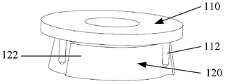
- Figure 1 is a schematic illustration of one embodiment of a circumferential locking mechanism in accordance with the present invention
- Figure 2 is a first component of the circumferential locking mechanism of Figure 1;
- Figure 3 is a second component of the circumferential locking mechanism of Figure 1;
- Figure 4 shows the engaged state of the first member and the second member of the circumferential locking mechanism of Figure 1;
- Figure 5 is a schematic illustration of a second component in another embodiment of a circumferential locking mechanism in accordance with the present invention.
- Figure 6 is a partial schematic view showing the engaged state of the second member and the first member of Figure 5;
- FIG. 7 is a schematic illustration of an embodiment of a battery locking device in accordance with the present invention.
- Figure 8 is a cross-sectional view of the battery locking device of Figure 7.
- the circumferential locking mechanism 100 includes a first component 110 and a second component 120.
- the pin 112 on the first component 110 abuts the limiting surface 122 on the second component 120, thereby limiting the relative circumferential direction of the first component 110 and the second component 120.
- any force applying means such as a spring, can be utilized to force the first member and the second member to engage, so that the third member functioning in this manner is not shown.
- the components to be circumferentially locked can be circumferentially fixed to the first component and the second component of the circumferential locking mechanism of the present invention, respectively.
- the circumferential locking mechanism of the invention achieves circumferential locking of the two components.
- the two components to be circumferentially locked include, but are not limited to, threaded connectors.
- FIGS. 2 and 3 show the first component 110 and the second component 120 of the circumferential locking mechanism of Fig. 1 in a perspective view, respectively.
- the first component 110 can include a first body 111 and a pin 112 extending axially from the first body 111, the pin 112 being distributed along the first circumference on the first body 111.
- the axial and circumferential directions are mutually perpendicular directions.
- the pin 112 is a cylindrical pin; as will be appreciated by those skilled in the art, the pin 112 can be in other common pin shapes, and will not be described herein.
- the circular first body 111 is shown in the figure, those skilled in the art can understand that, in a specific embodiment, the first body 111 can be in different specific forms, have different shapes and structures. Wait.
- the second component 120 includes a second body 121 and a limiting surface 122 on the second body.
- the stop surface 122 extends circumferentially and includes a plurality of segments 122', 122", 122"", and wherein each of the segments 122', 122", 122"" can be connected end to end.
- At least the end of the pin may be placed along the first circumference, while meeting the strength requirements.
- the radially-cut semi-cylindrical pin makes it more suitable for the starting or ending point of the segment.
- the radius of the stop faces at segments 122', 122", 122"' is bi-directionally tapered in the axial and circumferential directions.
- the limiting surface 122 is a peripheral side surface on the second body 121, wherein the distance from the pin 112 to the center of the first circumference needs to be larger than the radius of the peripheral side surface at the top but Less than the radius of the peripheral side at the bottom, the length of the pin 112 needs to be sufficient to engage the peripheral side at any location along the circumference of the peripheral side. With this arrangement, the pin 112 will abut the stop surface 122 on the second component 120 when the first component 110 and the second component 120 are engaged.
- the radius of the limiting surface 122 at each segment is bi-directionally tapered in the axial direction and the circumferential direction, it can be seen that when the pin 112 abuts against the limiting surface 122, its axial movement along the limiting surface 122 and circumferential rotation Will be locked.
- the first component 110 includes three pins 112 and the limiting surface 122 of the second component 120 includes three segments 122', 122", 122"".
- the numbers of the pins and segments are the same and are each evenly distributed along the circumference.
- the number of pins and segments are different, such as, but not limited to, when there are multiple segments, the number of pins may be less than the number of segments.
- the limiting surface may be composed only of segments connected end to end, and it is also conceivable to form a space between the segments.
- the pin 112 and the limiting surface 122 are arranged such that when the first component 110 is engaged with the second component 120, the pin 112 abuts the respective segments 122', 122", 122"" of the limiting surface 122.
- 4 shows the engaged state of the first component 110 and the second component 120 of the circumferential locking mechanism of FIG.
- the pin 112 can be abutted against the limiting surface 122, meaning that the direction of the limiting surface 122 is tapered such that it is inclined toward the direction of the pin 122, indicating that it is tapered in the direction of the arrow D2 in the axial direction.
- both the axial and circumferential directions include both forward and reverse directions
- bi-directional tapering along different axial and circumferential directions will enable the circumferential locking mechanism to achieve the first component and The locking function of the second component in different directions in the circumferential direction.
- the circumferential locking direction of the first member 110 and the second member 120 can be changed by changing the direction of the taper of the limiting surface 122.
- the limiting surface 122 tapers in the circumferential direction in the direction of the arrow D1, which rotates the locking first member 110 relative to the second member 120 in a direction opposite to D1 in the circumferential direction; conversely, if the limiting surface 122 tapers in a circumferential direction in a direction opposite to D1, which locks the first member 110 relative to the second member 120 in a circumferential direction relative to the second direction 120.
- the limiting surface 122 can also be an inner peripheral side on the second body 121 (eg, with reference to the inner peripheral side 224 of FIG. 5).
- the limiting surface 122 that is, the inner peripheral side surface, will form a recess on the surface of the second body 121, and the limiting surface 122 forms the circumferential side of the recess.
- the distance from the pin 112 to the center of the first circumference needs to be less than the radius of the inner circumference side at the top but greater than the radius of the inner circumference side at the bottom, and the length of the pin 112 needs to be sufficient along the
- the inner peripheral side is joined at any position of the circumference of the inner peripheral side.
- the pin can be abutted against the limiting surface, meaning that the direction of the limiting surface is tapered such that it is inclined toward the direction of the pin (the oblique direction will be opposite to the direction of the arrow D2 in Fig. 3).
- a circumferential locking mechanism having a single-sided beveled locking structure is a circumferential locking mechanism having a single-sided beveled locking structure.
- a circumferential locking mechanism having a double-sided beveled lock structure will be described below with reference to FIGS. 5 and 6.
- Figure 5 is a schematic illustration of a second component 220 in another embodiment of a circumferential locking mechanism in accordance with the present invention.
- Figure 6 shows, in partial schematic view, the engaged state of the second component 220 of Figure 5 and the first component 110.
- the third component that forces the first component 110 to engage the second component 220 is also omitted in FIG.
- the limiting surface 222 includes a peripheral side 223 and an inner peripheral side 224 on the second body 221.
- the distance from the pin 112 to the center of the first circumference needs to be greater than the radius of the peripheral side 223 at the top but less than the radius of the peripheral side 223 at the bottom, and the length of the pin 110 needs to be sufficient along the outer circumference.
- the peripheral side is engaged; at the same time, the distance from the pin 110 to the center of the first circumference needs to be less than the radius of the inner circumference side 224 at the top but greater than the radius of the inner circumference side 224 at the bottom, the pin 110 The length needs to be sufficient to engage the inner peripheral side at any position along the circumference of the inner peripheral side.
- the pin 110 will simultaneously abut the peripheral side 223 and the inner peripheral side 224, locking axial movement and circumferential rotation between the first component 110 and the second component 220.
- the outer peripheral side 223 and the inner peripheral side 224 preferably form a limiting slot 225. It can be understood that, at this time, the radial width of the pin 110 is smaller than the notch width of the limiting groove 225 but larger than the groove bottom width of the limiting groove 225, and the length of the pin 110 is sufficient at the circumference along the limiting groove 225.
- the outer peripheral side 223 and the inner peripheral side 224 are extended and joined at any position.
- the limiting groove 115 extends along the second circumference, the second circumference is the same as the first circumferential radius, and the center of the pin is on the first circumference, and the median line of the radial width of the limiting groove On the second circumference.
- the median line refers to a line connecting the midpoints in the radial width at each circumferential position of the limit groove. It can be understood that the limit groove will be easier to process and the locking effect is more effective.
- FIG 7 is a schematic illustration of one embodiment of a battery locking device in accordance with the present invention.
- Figure 8 is a cross-sectional view of the battery locking device of Figure 7. As can be seen from the figures, such a battery locking device includes a circumferential locking mechanism of the embodiment shown in Figures 1-4.
- the center pull rod of the battery locking device includes a holding portion 1, a threaded portion 2, and a spline portion 3, and the spring 4 is sleeved at the spline portion 3.
- the lever passes through the mounting bracket (not shown) at the battery pack and the mounting bracket (not shown) at the vehicle body, and the limit is limited.
- the member 320 is fixed to the mounting bracket of the battery pack, and the threaded portion 2 of the tie rod is screwed with the pallet on the mounting frame of the vehicle body, so that the mounting bracket at the battery pack and the mounting bracket at the vehicle body are clamped at the holding portion 1 to realize
- the battery pack is fixed on the body. It is conceivable that for the stable fixing of the battery pack, a plurality of illustrated battery locking devices are usually used simultaneously on the vehicle.
- a circumferential locking mechanism 300 is applied in the battery locking device, and the circumferential locking mechanism 300 is composed of the adjusting member 310 corresponding to the first member in FIGS. 1 to 4 and corresponding to FIGS. 1 to 4.
- the second component of the second component is formed by a limiting member 320, and the spring 4 is a third component for forcing the adjusting member 310 to engage with the limiting member 320.
- the adjustment member 310 is circumferentially fixed relative to the central tie rod, but is axially movable along the central pull rod; for example, without limitation, the adjustment member 310 may be centrally provided with a splined groove adapted to engage the spline portion 3.
- the pin 311 on the adjusting member 310 of the circumferential locking mechanism and the limiting surface 321 on the limiting member 320 correspond to the design of the pin and the limiting surface in FIGS. 1 to 2.
- the special adjustment tool is used to push the adjustment member 310 out of engagement with the limiting member 320, and then the adjusting member 310 is rotated to unscrew the threaded portion 2 and the mounting bracket of the vehicle body; when locking, use a special tool to upward
- the adjusting member 310 is disengaged from the engaging member 320, and then the adjusting member 310 is rotated to tighten the threaded portion 2 and the mounting bracket of the vehicle body.
- the spring 4 will push the adjusting member 310 to make the pin 311.
- the limiting member 320 locks the axial movement and the circumferential rotation of the adjusting member 310 against the limiting surface 321 of the limiting member 320.
- the screwing torque is usually used as a control index. That is, when the screwing torque reaches the target value, the screwing is stopped, and the special tool is withdrawn, and the adjusting member 310 and the limiting member 320 are locked by the circumferential locking mechanism to ensure the constant screwing torque.
- the pin 311 on the adjusting member 310 falls as the circumferential position of the adjusting member 310 falling under the spring force of the spring 4 is different.
- the depth of the lower limiting member 320 on the limiting surface is also different. Since the limiting surface 321 is bi-directionally tapered in the axial direction and the circumferential direction, a contraction passage in the rotation direction is formed. Due to the existence of the passage, the pin 311 on the adjusting member 310 cannot rotate relative to the limiting surface 321 and thus locks. The anti-looseness ensures a constant screwing torque.
- a plurality of pins 311 are provided on the adjustment member 310 and are semi-cylindrical pins at the ends. It will be appreciated that this will facilitate the engagement of the pins 311 at different segments of the limiting surface 321 to provide an increased continuous locking position.
- the battery locking device can be fixed to the power battery pack by the aforementioned second member, that is, the limiting member. Further, in such a vehicle, the power battery pack can be locked to the vehicle body of the vehicle by the aforementioned battery locking device.
Landscapes
- Engineering & Computer Science (AREA)
- General Engineering & Computer Science (AREA)
- Mechanical Engineering (AREA)
- Chemical & Material Sciences (AREA)
- Combustion & Propulsion (AREA)
- Transportation (AREA)
- Chemical Kinetics & Catalysis (AREA)
- Electrochemistry (AREA)
- General Chemical & Material Sciences (AREA)
- Arrangement Or Mounting Of Propulsion Units For Vehicles (AREA)
- Battery Mounting, Suspending (AREA)
- Mutual Connection Of Rods And Tubes (AREA)
Abstract
一种周向锁止机构、包括其的电池锁定装置、动力电池包及车辆。所述周向锁止机构(100)包括:第一部件(110),所述第一部件(110)包括第一本体(111)和自所述第一本体(111)沿轴向延伸的销(112),所述销(112)在所述第一本体(111)上沿第一圆周分布;第二部件(120),所述第二部件(120)包括第二本体(121)和所述第二本体(121)上的限位面(122),所述限位面(122)沿周向延伸且包括分段,所述限位面(122)在所述分段处的半径沿轴向和周向双向渐缩;以及迫使所述第一部件(110)和所述第二部件(120)接合的第三部件,其中,所述第一部件(110)和所述第二部件(120)布置成使得所述第一圆周和所述限位面(122)同轴,并且,在所述第一部件(110)与所述第二部件(120)接合时所述销(112)抵接所述限位面(122)。通过上述结构能够实现销(112)与限位面(122)的配合,可以完成连续锁止。
Description
本发明涉及部件的周向防松与锁止技术领域;具体地说,本发明涉及一种周向锁止机构。
进一步地,本发明还涉及一种包括其的电池锁定装置、动力电池包及车辆。
现有技术中经常会遇到需要限制两个部件的相对转动的情况。
例如,在螺纹连接中,如何保证连接预紧力的恒定是产业上的一个难题。目前常用的防松结构包括在一个易动螺纹件上提供多齿防松结构或槽形防松结构等。该结构只能提供有限的分度锁止定位。利用这些技术,在螺接扭矩达到预定值时螺纹件的接合角度是不确定的,如果在对应的角度处齿或槽不能咬合,则螺纹件仍存在松动的风险,并不能保持恒定的螺接扭矩。
周向防松与锁止技术还包括但不限于齿槽、键槽、销槽、销孔连接以及形状配合等,并且其应用也并不局限于螺纹连接中。这些技术中的结构同样只能提供有限的分度锁止定位。
虽然在理论上说布置尽可能多的分度锁止定位等能够无限地接近连续锁止定位,但在实际中不可能通过这种方式实现真正的连续锁止定位。
在新能源车辆的电池锁定装置中,为了实现动力电池包的快速装拆,需要对电池锁定装置的中心拉杆进行周向定位或锁止。例如,公告号为CN203543623U的中国专利中公开了一种电池锁定装置,其中通过调整件(与中心拉杆成为一体)上的销500与限位件上的槽205实现周向分度锁止定位。可见,在该应用中同样存在销301与槽101的接合位置同销500与槽205的接合位置不一致的情况。为了避免这种接合位置不一致的情况,现有技术中采用螺纹连接来取代销301与槽101,但仍然具有不能连续锁止定位、不能保持恒定的螺接扭矩的缺点。
发明内容
本发明的目的是提供一种能够克服现有技术中的前述缺点的周向锁止机构。
进一步地,本发明的目的还在于提供一种包括前述周向锁止机构的电池锁定装置、动力电池包及车辆。
为了实现前述目的,本发明的第一方面提供了一种周向锁止机构,其中,所述周向 锁止机构包括:
第一部件,所述第一部件包括第一本体和自所述第一本体沿轴向延伸的销,所述销在所述第一本体上沿第一圆周分布;
第二部件,所述第二部件包括第二本体和所述第二本体上的限位面,所述限位面沿周向延伸且包括分段,所述限位面在所述分段处的半径沿轴向和周向双向渐缩;以及
迫使所述第一部件和所述第二部件接合的第三部件,
其中,所述第一部件和所述第二部件布置成使得所述第一圆周和所述限位面同轴,并且,在所述第一部件与所述第二部件接合时所述销抵接所述限位面。
可选地,在如前所述的周向锁止机构中,所述销与所述分段数量相同,且分别沿周向均布。
可选地,在如前所述的周向锁止机构中,各个所述分段首尾相连。
可选地,在如前所述的周向锁止机构中,所述销为圆柱销。
可选地,在如前所述的周向锁止机构中,所述销至少在末端处为沿相对于所述第一圆周的径向剖切的半圆柱销。
可选地,在如前所述的周向锁止机构中,所述第三部件是螺旋弹簧。
可选地,在如前所述的周向锁止机构中,所述限位面为所述第二本体上的外周侧面,并且,所述销至所述第一圆周的圆心的距离大于所述外周侧面在顶部各处的半径但小于所述外周侧面在底部各处的半径,所述销的长度足以在沿所述外周侧面的圆周的任何位置处接合所述外周侧面。
可选地,在如前所述的周向锁止机构中,所述限位面为所述第二本体上的内周侧面,并且,所述销至所述第一圆周的圆心的距离小于所述内周侧面在顶部各处的半径但大于所述内周侧面在底部各处的半径,所述销的长度足以在沿所述内周侧面的圆周的任何位置处接合所述内周侧面。
可选地,在如前所述的周向锁止机构中,所述限位面包括所述第二本体上的外周侧面和内周侧面,并且,所述销至所述第一圆周的圆心的距离大于所述外周侧面在顶部各处的半径但小于所述外周侧面在底部各处的半径,所述销的长度足以在沿所述外周侧面的圆周的任何位置处接合所述外周侧面;所述销至所述第一圆周的圆心的距离小于所述内周侧面在顶部各处的半径但大于所述内周侧面在底部各处的半径,所述销的长度足以在沿所述内周侧面的圆周的任何位置处接合所述内周侧面。
可选地,在如前所述的周向锁止机构中,所述外周侧面和所述内周侧面形成限位 槽,并且,所述销的径向宽度小于所述限位槽各处的槽口宽度但大于所述限位槽各处的槽底宽度,并且所述销的长度足以在沿所述限位槽的周向的任何位置处伸进并接合所述外周侧面和所述内周侧面。
可选地,在如前所述的周向锁止机构中,所述限位槽沿第二圆周延伸,所述第二圆周与所述第一圆周半径相同,并且,所述所述销的中心在所述第一圆周上,所述限位槽的径向宽度的中位线在所述第二圆周上。
为了实现前述目的,本发明的第二方面提供了一种电池锁定装置,其中,所述电池锁定装置包括如前述第一方面中任一项所述的周向锁止机构。
可选地,在如前所述的电池锁定装置中,所述第一部件为所述电池锁定装置的调整件,其相对于所述电池锁定装置的中心拉杆周向固定,但能够沿所述中心拉杆轴向移动;所述第二部件为所述电池锁定装置的限位件。
为了实现前述目的,本发明的第三方面提供了一种用于车辆的动力电池包,所述动力电池包包括前如第二方面中任一项所述的电池锁定装置。
可选地,在如前所述的动力电池包中,所述电池锁定装置通过所述第二部件固定至所述动力电池包。
为了实现前述目的,本发明的第四方面提供了一种车辆,所述车辆包括通过如前述第二方面中任一项所述的电池锁定装置。
可选地,在如前所述的车辆中,所述车辆的动力电池包通过所述电池锁定装置而锁定于所述车辆。
在根据本发明的前述周向锁止机构、包括其的电池锁止机构、动力电池包及车辆中,采用具有双向渐缩的限位面,通过销与限位面的配合完成连续锁止,即无论销落到任何周向位置都能进行锁止;并且本方案结构简单、锁止可靠。
参照附图,本发明的公开内容将更加显然。应当了解,这些附图仅仅用于说明的目的,而并非意在对本发明的保护范围构成限制。图中:
图1是根据本发明的周向锁止机构的一种实施方式的示意图;
图2是图1中周向锁止机构的第一部件;
图3是图1中周向锁止机构的第二部件;
图4示出了图1中周向锁止机构的第一部件和第二部件的接合状态;
图5是根据本发明的周向锁止机构的另一实施方式中第二部件的示意图;
图6以局部示意图示出了图5中第二部件与第一部件的接合状态;
图7是根据本发明的电池锁定装置的一种实施方式的示意图;以及
图8是图7中电池锁定装置的剖面示意图。
下面参照附图详细地说明本发明的具体实施方式。在各附图中,相同的附图标记表示相同或相应的技术特征。
图1是根据本发明的周向锁止机构的一种实施方式的示意图。从图中可以看出,该周向锁止机构100包括第一部件110和第二部件120。当第一部件110和第二部件120接合时,第一部件110上的销112抵接住第二部件120上的限位面122,从而限制第一部件110和第二部件120的相对周向转动。容易理解,所属领域的技术人员了解可以利用弹簧等任何施力装置来迫使第一部件和第二部件接合,所以在图中未示出起此作用的第三部件。
可以想到,在需要将任意两个部件进行周向锁止的情况下,可以将这些待被周向锁止的部件分别周向固定于本发明的周向锁止机构的第一部件和第二部件,即可通过本发明的周向锁止机构实现该两个部件的周向锁止。该两个待被周向锁止的部件包括但不限于螺纹连接件。
图2和图3分别以立体图详细示出了图1中周向锁止机构的第一部件110和第二部件120。
依据图2可以看出,第一部件110可以包括第一本体111和自第一本体111沿轴向延伸的销112,销112在第一本体111上沿第一圆周分布。从图中可以看出,轴向和圆周方向是相互垂直的方向。在图示示例中,销112为圆柱销;依此教示,所属领域的技术人员可以想到,该销112可以呈其它常见的销形状,在此不再一一例举。同时,尽管图中示出了圆形的第一本体111,但是,所属领域的技术人员可以了解,在具体的实施方式中,第一本体111可以呈不同的具体形式,具有不同的形状、结构等。
依据图3可以看出,第二部件120包括第二本体121和第二本体上的限位面122。如图中所示,限位面122沿周向延伸且包含多个分段122′、122″、122″′,且其中各个分段122′、122″、122″′可以首尾相连。第一部件110与第二部件120接合时销112抵接限位面122,这是通过将第一部件和第二部件布置成使得第一圆周和限位面同轴而实现的。考虑到销112与限位面122上相连分段的过渡处的接合,为了增加连续的锁止位置,在满足强度要求的前提下,可以将销的至少末端处设置成沿相对于第一圆周的径向剖切的半圆柱销,使其更适应于分段的起始点或终止点。如图中所示,限位面在分段122′、122″、122″′处的半径沿 轴向和周向双向渐缩。
在图1至4中示出的是限位面122为第二本体121上的外周侧面的情况,其中,销112至第一圆周的圆心的距离需要大于该外周侧面在顶部各处的半径但小于该外周侧面在底部各处的半径,销112的长度需要足以在沿该外周侧面的圆周的任何位置处接合该外周侧面。通过这种设置,在第一部件110和第二部件120相接合时,销112将抵住第二部件120上的限位面122。由于限位面122在每个分段处的半径沿轴向和周向双向渐缩,可见,当销112抵住限位面122时,其沿限位面122的轴向移动及周向转动将被锁止。
在图示实施方式中,第一部件110包括三个销112、第二部件120的限位面122包括三个分段122′、122″、122″′。所属领域的技术人员可以想到,在其它实施方式中也可以设置其它数量例如一个、两个或更多个销和分段。优选地,这些销和分段的数量相同,并且各自沿圆周均布。所属领域的技术人员也可以想到销和分段数量不同的情况,例如但不限于,当存在多个分段时,销的数量可以少于分段的数量。另外,可以理解,在可选的实施方式中,限位面可以仅由首尾相连的分段组成,也可以考虑在各分段间形成有间隔。
销112和限位面122设置成当第一部件110与第二部件120接合时销112抵接住限位面122的各个分段122′、122″、122″′。图4示出了图1中周向锁止机构的第一部件110和第二部件120的接合状态。此处,销112能够与限位面122相抵,意味着限位面122渐缩的方向使得其朝向销122的方向倾斜,说明其在轴向上沿箭头D2的方向渐缩。
依据前述教示,所属领域的技术人员可以了解,由于轴向和周向均包括正反两个方向,所以,沿不同的轴向和周向方向的双向渐缩将使得周向锁止机构能够实现第一部件和第二部件沿周向的不同方向的锁止功能。从而,通过改变限位面122的渐缩的方向将可以改变第一部件110和第二部件120的周向锁止方向。例如,在图中限位面122在周向上沿箭头D1方向渐缩,其将锁止第一部件110相对于第二部件120沿与D1相反的方向相对周向转动;相反,如果限位面122在周向上沿与D1相反的方向渐缩,其将锁止第一部件110相对于第二部件120沿D1方向相对周向转动。
相对于图1至图4中所示的实施方式,可以想到,限位面122也可以为第二本体121上的内周侧面(例如参考图5中的内周侧面224)。在这种情况下,限位面122即内周侧面将在第二本体121的表面上形成一个凹部,该限位面122形成该凹部的周侧面。
在这种情况下,销112至第一圆周的圆心的距离需要小于该内周侧面在顶部各处的半径但大于该内周侧面在底部各处的半径,销112的长度需要足以在沿该内周侧面的圆周的任何位置处接合内周侧面。通过这种设置,在第一部件和第二部件相接合时,销112将抵住第 二部件上的限位面。由于限位面在每个分段处的半径沿轴向和周向双向渐缩,可见,当销抵住限位面时,其沿限位面的轴向移动及周向转动将被锁止。此外,销能够与限位面相抵,意味着限位面渐缩的方向使得其朝向销的方向倾斜(倾斜方向将与图3中箭头D2的方向相反)。
关于图1至图4中实施方式的特征和描述同样适用于这种实施方式中的周向锁止机构的第一部件和第二部件,此处不再赘述。
以上为具有单边斜面防松结构的周向锁止机构。下面结合图5和图6描述具有双边斜面防松结构的周向锁止机构。
图5是根据本发明的周向锁止机构的另一实施方式中第二部件220的示意图。图6以局部示意图示出了图5中第二部件220与第一部件110的接合状态。图6中同样略去了迫使第一部件110与第二部件220接合的第三部件。从图中可以了解,在该实施方式中,限位面222包括第二本体221上的外周侧面223和内周侧面224。
在这种实施方式中,销112至第一圆周的圆心的距离需要大于外周侧面223在顶部各处的半径但小于外周侧面223在底部各处的半径,销110的长度需要足以在沿外周侧面的圆周的任何位置处接合外周侧面;同时,销110至第一圆周的圆心的距离需要小于内周侧面224在顶部各处的半径但大于内周侧面224在底部各处的半径,销110的长度需要足以在沿内周侧面的圆周的任何位置处接合内周侧面。当第一部件110与第二部件220接合时,销110将同时抵住外周侧面223和内周侧面224,锁止第一部件110和第二部件220之间的轴向移动和周向转动。
在图示实施方式中,外周侧面223和内周侧面224优选地形成了限位槽225。可以了解,此时,销110的径向宽度小于限位槽225各处的槽口宽度但大于限位槽225各处的槽底宽度,并且销110的长度足以在沿限位槽225的周向的任何位置处伸进并接合外周侧面223和内周侧面224。
在更优选的实施方式中,限位槽115沿第二圆周延伸,第二圆周与第一圆周半径相同,并且,销的中心在第一圆周上,限位槽的径向宽度的中位线在第二圆周上。此处,中位线指的是在限位槽各个周向位置处径向宽度上的中点的连线。可以理解,这种限位槽将更加易于加工,并且锁止效果更加有效。
图7是根据本发明的电池锁定装置的一种实施方式的示意图。图8是图7中电池锁定装置的剖面示意图。从图中可以看出,这种电池锁定装置包括有图1至图4中所示实施方式的周向锁止机构。
在图7中,电池锁定装置的中心拉杆包括保持部1、螺纹部2和花键部3,弹簧4套接在花键部3处。在使用中,例如在用该电池锁定装置将动力电池锁定在车辆上时,拉杆依次穿过电池包处的安装架(未图示)及车身处的安装架(未图示),并且限位件320固定于电池包的安装架、拉杆的螺纹部2与车身处安装架上的托板螺接,从而将电池包处的安装架及车身处的安装架夹持在保持部1处,实现电池包在车身上的固定。可以想到,为了电池包的稳定固定,在车辆上通常会同时使用多个图示的电池锁定装置。
为了实现电池包的快速拆装,电池锁止装置中应用了周向锁止机构300,周向锁止机构300由对应于图1至图4中的第一部件的调整件310和对应于图1至图4中的第二部件的限位件320组成,弹簧4为迫使调整件310与限位件320接合的第三部件。调整件310相对于中心拉杆周向固定,但能够沿中心拉杆轴向移动;例如但不限于,调整件310中心可以布置有适于与花键部3接合的花键槽。
可以看出,该周向锁止机构的调整件310上的销311和限位件320上的限位面321对应于图1至图2中的销和限位面的设计。在解锁时,利用专用工具向上推动调整件310脱离与限位件320的接合,然后旋转调整件310从而旋开螺纹部2与车身处安装架的螺接;在锁紧时,利用专用工具向上推动调整件310脱离与限位件320的接合,然后旋转调整件310从而旋紧螺纹部2与车身处安装架的螺接,取下专用工具后,弹簧4将推动调整件310使得其销311抵住限位件320上的限位面321,限位件320锁止调整件310的轴向移动和周向转动。
在如上的操作中,利用专用工具旋紧中心拉杆上的螺纹部2与车身处安装架的螺接时,通常是以螺接扭矩作为控制指标的。即,当螺接扭矩达到目标值时就停止继续拧紧,并且退出专用工具,利用周向锁止机构将调整件310和限位件320锁紧,以保证螺接扭矩的恒定。
根据图7和图8所示的电池锁定装置,在除去专用工具时,随着调整件310在弹簧4的弹簧力的作用下而下落的周向位置不同,调整件310上的销311落到下部限位件320的限位面上的深度也不同。由于限位面321沿轴向和周向双向渐缩,就形成了旋转方向的收缩通道,由于该通道的存在,调整件310上的销311就无法相对于限位面321旋转,进而锁止防松,保证了螺接扭矩的恒定。
在图7中可以看到,调整件310上设置了多个销311,并且在末端处为半圆柱销。可以了解,这将有利于销311在限位面321的不同分段处的接合,以提供增加的连续锁止位置。
根据上文描述,所属领域的技术人员可以想到包括这种周向锁止机构或电池锁定装置的动力电池包及车辆。例如,为了方便向车辆上安装动力电池包,可以通过前述第二部件即限位件将电池锁定装置固定于动力电池包。另外,在这样的车辆中,动力电池包可以通过前述的电池锁定装置而锁定到车辆的车身。
本发明的技术范围不仅仅局限于上述说明中的内容。所属领域技术人员可以在不脱离本发明技术思想的前提下,可以将不同实施方式的特征进行结合,或者对上述实施方式进行多种变形和修改,而这些结合、变形和修改均应当属于本发明的范围内。
Claims (17)
- 一种周向锁止机构,其特征在于,所述周向锁止机构包括:第一部件,所述第一部件包括第一本体和自所述第一本体沿轴向延伸的销,所述销在所述第一本体上沿第一圆周分布;第二部件,所述第二部件包括第二本体和所述第二本体上的限位面,所述限位面沿周向延伸且包括分段,所述限位面在所述分段处的半径沿轴向和周向双向渐缩;以及迫使所述第一部件和所述第二部件接合的第三部件,其中,所述第一部件和所述第二部件布置成使得所述第一圆周和所述限位面同轴,并且,在所述第一部件与所述第二部件接合时所述销抵接所述限位面。
- 如权利要求1所述的周向锁止机构,其中,所述销与所述分段数量相同,且分别沿周向均布。
- 如权利要求1或2所述的周向锁止机构,其中,各个所述分段首尾相连。
- 如权利要求1所述的周向锁止机构,其中,所述销为圆柱销。
- 如权利要求4所述的周向锁止机构,其中,所述销至少在末端处为沿相对于所述第一圆周的径向剖切的半圆柱销。
- 如权利要求1所述的周向锁止机构,其中,所述第三部件是螺旋弹簧。
- 如权利要求1至6中任一项所述的周向锁止机构,其中,所述限位面为所述第二本体上的外周侧面,并且,所述销至所述第一圆周的圆心的距离大于所述外周侧面在顶部各处的半径但小于所述外周侧面在底部各处的半径,所述销的长度足以在沿所述外周侧面的圆周的任何位置处接合所述外周侧面。
- 如权利要求1至6中任一项所述的周向锁止机构,其中,所述限位面为所述第二本体上的内周侧面,并且,所述销至所述第一圆周的圆心的距离小于所述内周侧面在顶部各处的半径但大于所述内周侧面在底部各处的半径,所述销的长度足以在沿所述内周侧面的圆周的任何位置处接合所述内周侧面。
- 如权利要求1至6中任一项所述的周向锁止机构,其中,所述限位面包括所述第二本体上的外周侧面和内周侧面,并且:所述销至所述第一圆周的圆心的距离大于所述外周侧面在顶部各处的半径但小于所述外周侧面在底部各处的半径,所述销的长度足以在沿所述外周侧面的圆周的任何位置处接合所述外周侧面;所述销至所述第一圆周的圆心的距离小于所述内周侧面在顶部各处的半径但大于所述内周侧面在底部各处的半径,所述销的长度足以在沿所述内周侧面的圆周的任何位置处接合所述内周侧面。
- 如权利要求9所述的周向锁止机构,其中,所述外周侧面和所述内周侧面形成限位槽,并且,所述销的径向宽度小于所述限位槽各处的槽口宽度但大于所述限位槽各处的槽底宽度,并且所述销的长度足以在沿所述限位槽的周向的任何位置处伸进并接合所述外周侧面和所述内周侧面。
- 如权利要求10所述的周向锁止机构,其中,所述限位槽沿第二圆周延伸,所述第二圆周与所述第一圆周半径相同,并且,所述所述销的中心在所述第一圆周上,所述限位槽的径向宽度的中位线在所述第二圆周上。
- 一种电池锁定装置,其特征在于,所述电池锁定装置包括如前述权利要求1至11中任一项所述的周向锁止机构。
- 如权利要求11所述的电池锁定装置,其中,所述第一部件为所述电池锁定装置的调整件,其相对于所述电池锁定装置的中心拉杆周向固定,但能够沿所述中心拉杆轴向移动;所述第二部件为所述电池锁定装置的限位件。
- 一种用于车辆的动力电池包,其特征在于,所述动力电池包包括如权利要求12或13所述的电池锁定装置。
- 如权利要求14所述的动力电池包,其中,所述电池锁定装置通过所述第二部件固定至所述动力电池包。
- 一种车辆,其特征在于,所述车辆包括如权利要求12或13所述的电池锁定装置。
- 如权利要求16所述的车辆,其中,所述车辆的动力电池包通过所述电池锁定装置而锁定于所述车辆。
Priority Applications (2)
| Application Number | Priority Date | Filing Date | Title |
|---|---|---|---|
| US16/468,793 US11458824B2 (en) | 2016-12-12 | 2017-12-07 | Circumferential lock mechanism, battery locking device, power battery pack and vehicle |
| EP17881487.7A EP3552855B1 (en) | 2016-12-12 | 2017-12-07 | Circumferential lock mechanism, battery locking device, power battery pack and vehicle |
Applications Claiming Priority (2)
| Application Number | Priority Date | Filing Date | Title |
|---|---|---|---|
| CN201611137583.8A CN106979192B (zh) | 2016-12-12 | 2016-12-12 | 周向锁止机构、电池锁定装置、动力电池包及车辆 |
| CN201611137583.8 | 2016-12-12 |
Publications (1)
| Publication Number | Publication Date |
|---|---|
| WO2018108014A1 true WO2018108014A1 (zh) | 2018-06-21 |
Family
ID=59340774
Family Applications (1)
| Application Number | Title | Priority Date | Filing Date |
|---|---|---|---|
| PCT/CN2017/114895 Ceased WO2018108014A1 (zh) | 2016-12-12 | 2017-12-07 | 周向锁止机构、电池锁定装置、动力电池包及车辆 |
Country Status (5)
| Country | Link |
|---|---|
| US (1) | US11458824B2 (zh) |
| EP (1) | EP3552855B1 (zh) |
| CN (1) | CN106979192B (zh) |
| TW (1) | TWI732075B (zh) |
| WO (1) | WO2018108014A1 (zh) |
Cited By (1)
| Publication number | Priority date | Publication date | Assignee | Title |
|---|---|---|---|---|
| CN113682192A (zh) * | 2021-08-30 | 2021-11-23 | 安徽巨一科技股份有限公司 | 一种汽车电池包快速锁止机构 |
Families Citing this family (14)
| Publication number | Priority date | Publication date | Assignee | Title |
|---|---|---|---|---|
| CN106979192B (zh) * | 2016-12-12 | 2019-03-26 | 上海蔚来汽车有限公司 | 周向锁止机构、电池锁定装置、动力电池包及车辆 |
| CN106740029B (zh) * | 2016-12-29 | 2024-04-09 | 上海蔚来汽车有限公司 | 周向锁止机构、包括其的电池锁定装置、动力电池包及车辆 |
| CN206351680U (zh) * | 2017-01-04 | 2017-07-25 | 上海蔚来汽车有限公司 | 自适应调整位置的加解锁夹具 |
| CN109674517B (zh) * | 2017-10-18 | 2020-09-11 | 江苏风和医疗器材股份有限公司 | 一种高度调节装置 |
| CN109515148A (zh) * | 2018-05-29 | 2019-03-26 | 蔚来汽车有限公司 | 周向锁止机构、包括其的电池锁定装置、动力电池包及车辆 |
| CN110711059B (zh) * | 2019-11-08 | 2025-03-04 | 钟静 | 一种双向卡扣装置 |
| CN111002844B (zh) * | 2019-12-25 | 2024-04-09 | 上海玖行能源科技有限公司 | 具备换电和充电功能的载重卡车及其供电方法 |
| CN114801861A (zh) | 2020-01-02 | 2022-07-29 | 奥动新能源汽车科技有限公司 | 换电设备的视觉定位方法及系统 |
| CN111267789B (zh) * | 2020-01-31 | 2022-08-05 | 山东蓝擎重工科技有限公司 | 一种新能源车换电系统 |
| CN119261592B (zh) * | 2020-04-02 | 2025-10-24 | 奥动新能源股份有限公司 | 连接装置、电池端连接装置、电动汽车及电池包组件 |
| CN112158062B (zh) * | 2020-09-29 | 2022-03-18 | 东风汽车集团有限公司 | 一种电池箱体锁止装置及电池箱体的车身连接结构 |
| EP4177091B1 (en) * | 2021-09-17 | 2025-01-29 | Contemporary Amperex Technology (Hong Kong) Limited | Quick swap lock assembly and locking apparatus using said assembly |
| CN114069146B (zh) * | 2021-10-28 | 2024-04-09 | 中国第一汽车股份有限公司 | 一种口琴管式液冷板固定装置、设计方法、电池及车辆 |
| CN116394736A (zh) * | 2023-03-02 | 2023-07-07 | 深圳精智机器有限公司 | 分体式锁止机构和设备 |
Citations (7)
| Publication number | Priority date | Publication date | Assignee | Title |
|---|---|---|---|---|
| US3816882A (en) * | 1971-05-14 | 1974-06-18 | Matsushita Electric Industrial Co Ltd | Clamping units for use in packaging |
| CN202106830U (zh) * | 2011-05-31 | 2012-01-11 | 许继电源有限公司 | 一种电动汽车及其电池箱用导向机构 |
| CN203254949U (zh) * | 2013-05-16 | 2013-10-30 | 王俊 | 旋转锁定机构及其挂接组件、挂接配合组件 |
| CN203543623U (zh) | 2013-10-31 | 2014-04-16 | 深圳精智机器有限公司 | 电池锁止机构 |
| CN104022240A (zh) * | 2014-05-23 | 2014-09-03 | 亿源动力(北京)科技有限公司 | 车载电池及具有该车载电池的车辆 |
| CN106979192A (zh) * | 2016-12-12 | 2017-07-25 | 蔚来汽车有限公司 | 周向锁止机构、电池锁定装置、动力电池包及车辆 |
| CN206617391U (zh) * | 2016-12-12 | 2017-11-07 | 蔚来汽车有限公司 | 周向锁止机构、电池锁定装置、动力电池包及车辆 |
Family Cites Families (13)
| Publication number | Priority date | Publication date | Assignee | Title |
|---|---|---|---|---|
| US5022875A (en) * | 1989-10-20 | 1991-06-11 | Brunswick Corporation | Marine propeller locking tab washer |
| US6669419B1 (en) * | 2002-01-25 | 2003-12-30 | Radio Systems Corporation | Probe locking washer |
| US7008158B2 (en) * | 2004-02-05 | 2006-03-07 | Madden Iii James William | Bolt or nut locking fastener and fastening system |
| US20060216129A1 (en) * | 2005-03-24 | 2006-09-28 | Chen-Mao Lin | Loose-proof screw bolt |
| TWI491093B (zh) * | 2013-10-16 | 2015-07-01 | 台灣立凱綠能移動股份有限公司 | 一種電動車專用的電池接點的鎖固狀態確認手段 |
| FR3015774A1 (fr) * | 2013-12-24 | 2015-06-26 | Commissariat Energie Atomique | Systeme de fixation amovible d'une batterie a un support |
| DE102014221500A1 (de) * | 2014-06-10 | 2015-12-17 | Hyundai Motor Company | Vorrichtung zur Verhinderung einer Schraubenablösung |
| CN204175767U (zh) * | 2014-10-20 | 2015-02-25 | 浙江荣得利航空部件有限公司 | 双重防松脱螺母套件 |
| US9568299B2 (en) * | 2015-04-17 | 2017-02-14 | Toyota Motor Engineering & Manufacturing North America, Inc. | Tool for use with a two piece grommet |
| CN205039467U (zh) * | 2015-10-25 | 2016-02-17 | 河北建材职业技术学院 | 通信线缆涨皮器 |
| CN106080159B (zh) * | 2016-05-25 | 2019-03-22 | 上海蔚来汽车有限公司 | 锁体组件、动力电池、其锁止机构及使用方法、交通工具 |
| CN106740029B (zh) * | 2016-12-29 | 2024-04-09 | 上海蔚来汽车有限公司 | 周向锁止机构、包括其的电池锁定装置、动力电池包及车辆 |
| JP6934161B2 (ja) * | 2017-02-24 | 2021-09-15 | ボルトエンジニア株式会社 | 締結構造 |
-
2016
- 2016-12-12 CN CN201611137583.8A patent/CN106979192B/zh active Active
-
2017
- 2017-12-07 WO PCT/CN2017/114895 patent/WO2018108014A1/zh not_active Ceased
- 2017-12-07 US US16/468,793 patent/US11458824B2/en active Active
- 2017-12-07 EP EP17881487.7A patent/EP3552855B1/en active Active
- 2017-12-08 TW TW106143248A patent/TWI732075B/zh active
Patent Citations (7)
| Publication number | Priority date | Publication date | Assignee | Title |
|---|---|---|---|---|
| US3816882A (en) * | 1971-05-14 | 1974-06-18 | Matsushita Electric Industrial Co Ltd | Clamping units for use in packaging |
| CN202106830U (zh) * | 2011-05-31 | 2012-01-11 | 许继电源有限公司 | 一种电动汽车及其电池箱用导向机构 |
| CN203254949U (zh) * | 2013-05-16 | 2013-10-30 | 王俊 | 旋转锁定机构及其挂接组件、挂接配合组件 |
| CN203543623U (zh) | 2013-10-31 | 2014-04-16 | 深圳精智机器有限公司 | 电池锁止机构 |
| CN104022240A (zh) * | 2014-05-23 | 2014-09-03 | 亿源动力(北京)科技有限公司 | 车载电池及具有该车载电池的车辆 |
| CN106979192A (zh) * | 2016-12-12 | 2017-07-25 | 蔚来汽车有限公司 | 周向锁止机构、电池锁定装置、动力电池包及车辆 |
| CN206617391U (zh) * | 2016-12-12 | 2017-11-07 | 蔚来汽车有限公司 | 周向锁止机构、电池锁定装置、动力电池包及车辆 |
Non-Patent Citations (1)
| Title |
|---|
| See also references of EP3552855A4 |
Cited By (1)
| Publication number | Priority date | Publication date | Assignee | Title |
|---|---|---|---|---|
| CN113682192A (zh) * | 2021-08-30 | 2021-11-23 | 安徽巨一科技股份有限公司 | 一种汽车电池包快速锁止机构 |
Also Published As
| Publication number | Publication date |
|---|---|
| CN106979192A (zh) | 2017-07-25 |
| EP3552855A4 (en) | 2020-07-08 |
| TW201826591A (zh) | 2018-07-16 |
| US20200094666A1 (en) | 2020-03-26 |
| EP3552855A1 (en) | 2019-10-16 |
| TWI732075B (zh) | 2021-07-01 |
| CN106979192B (zh) | 2019-03-26 |
| EP3552855B1 (en) | 2021-09-15 |
| US11458824B2 (en) | 2022-10-04 |
Similar Documents
| Publication | Publication Date | Title |
|---|---|---|
| WO2018108014A1 (zh) | 周向锁止机构、电池锁定装置、动力电池包及车辆 | |
| EP3564055B1 (en) | Battery securing device, traction battery comprising the same and vehicle | |
| US6811364B2 (en) | Quick connecting threaded coupler | |
| CN105987055B (zh) | 快速紧固件、利用其连接两个部件的方法及其制备方法 | |
| CN104428544A (zh) | 公差补偿构件 | |
| US9664235B2 (en) | Shaft coupling assembly and method for coupling shafts | |
| KR102243164B1 (ko) | 체결 요소 및 체결 조립체 | |
| PT786603E (pt) | Porca de controlo de carga previa que se fecha a si propria | |
| US9599142B2 (en) | Lock washer | |
| US20130315665A1 (en) | Mounting device | |
| CN106660140B (zh) | 卡盘装置 | |
| CN206617391U (zh) | 周向锁止机构、电池锁定装置、动力电池包及车辆 | |
| US2147357A (en) | Multiple disk expansion anchor | |
| US11466723B2 (en) | Nut-locking device and associated assembly unit | |
| KR101669549B1 (ko) | 결합해제가 가능한 볼트형 풀림방지 체결구 | |
| HK1239779A (zh) | 周向鎖止機構、電池鎖定裝置、動力電池包及車輛 | |
| HK1239779A1 (zh) | 周向锁止机构、电池锁定装置、动力电池包及车辆 | |
| JP5880814B2 (ja) | 摺動式スプライン軸装置およびその製造方法 | |
| CN105172872B (zh) | 操纵装置及其组装方法 | |
| HK1239779B (zh) | 周向锁止机构、电池锁定装置、动力电池包及车辆 | |
| US11629746B2 (en) | Nut-locking device and associated assembly unit | |
| US20170361431A1 (en) | Fastener removal apparatus | |
| US20140215789A1 (en) | Rotational Locking and Attachment Mechanism | |
| KR101534442B1 (ko) | 로크 볼트 어셈블리 | |
| US11519450B2 (en) | Nut locking device and assembly for mounting same |
Legal Events
| Date | Code | Title | Description |
|---|---|---|---|
| 121 | Ep: the epo has been informed by wipo that ep was designated in this application |
Ref document number: 17881487 Country of ref document: EP Kind code of ref document: A1 |
|
| NENP | Non-entry into the national phase |
Ref country code: DE |
|
| ENP | Entry into the national phase |
Ref document number: 2017881487 Country of ref document: EP Effective date: 20190712 |