WO2018110315A1 - 送信装置、送信方法、受信装置、及び、受信方法 - Google Patents
送信装置、送信方法、受信装置、及び、受信方法 Download PDFInfo
- Publication number
- WO2018110315A1 WO2018110315A1 PCT/JP2017/043236 JP2017043236W WO2018110315A1 WO 2018110315 A1 WO2018110315 A1 WO 2018110315A1 JP 2017043236 W JP2017043236 W JP 2017043236W WO 2018110315 A1 WO2018110315 A1 WO 2018110315A1
- Authority
- WO
- WIPO (PCT)
- Prior art keywords
- length
- header
- fec
- bits
- byte
- Prior art date
- Legal status (The legal status is an assumption and is not a legal conclusion. Google has not performed a legal analysis and makes no representation as to the accuracy of the status listed.)
- Ceased
Links
Images


















Classifications
-
- H—ELECTRICITY
- H04—ELECTRIC COMMUNICATION TECHNIQUE
- H04L—TRANSMISSION OF DIGITAL INFORMATION, e.g. TELEGRAPHIC COMMUNICATION
- H04L1/00—Arrangements for detecting or preventing errors in the information received
- H04L1/004—Arrangements for detecting or preventing errors in the information received by using forward error control
- H04L1/0072—Error control for data other than payload data, e.g. control data
-
- H—ELECTRICITY
- H04—ELECTRIC COMMUNICATION TECHNIQUE
- H04N—PICTORIAL COMMUNICATION, e.g. TELEVISION
- H04N21/00—Selective content distribution, e.g. interactive television or video on demand [VOD]
- H04N21/20—Servers specifically adapted for the distribution of content, e.g. VOD servers; Operations thereof
- H04N21/23—Processing of content or additional data; Elementary server operations; Server middleware
- H04N21/235—Processing of additional data, e.g. scrambling of additional data or processing content descriptors
-
- H—ELECTRICITY
- H04—ELECTRIC COMMUNICATION TECHNIQUE
- H04H—BROADCAST COMMUNICATION
- H04H20/00—Arrangements for broadcast or for distribution combined with broadcast
- H04H20/86—Arrangements characterised by the broadcast information itself
- H04H20/95—Arrangements characterised by the broadcast information itself characterised by a specific format, e.g. an encoded audio stream
-
- H—ELECTRICITY
- H04—ELECTRIC COMMUNICATION TECHNIQUE
- H04L—TRANSMISSION OF DIGITAL INFORMATION, e.g. TELEGRAPHIC COMMUNICATION
- H04L1/00—Arrangements for detecting or preventing errors in the information received
-
- H—ELECTRICITY
- H04—ELECTRIC COMMUNICATION TECHNIQUE
- H04L—TRANSMISSION OF DIGITAL INFORMATION, e.g. TELEGRAPHIC COMMUNICATION
- H04L1/00—Arrangements for detecting or preventing errors in the information received
- H04L1/0001—Systems modifying transmission characteristics according to link quality, e.g. power backoff
- H04L1/0006—Systems modifying transmission characteristics according to link quality, e.g. power backoff by adapting the transmission format
- H04L1/0007—Systems modifying transmission characteristics according to link quality, e.g. power backoff by adapting the transmission format by modifying the frame length
- H04L1/0008—Systems modifying transmission characteristics according to link quality, e.g. power backoff by adapting the transmission format by modifying the frame length by supplementing frame payload, e.g. with padding bits
-
- H—ELECTRICITY
- H04—ELECTRIC COMMUNICATION TECHNIQUE
- H04L—TRANSMISSION OF DIGITAL INFORMATION, e.g. TELEGRAPHIC COMMUNICATION
- H04L1/00—Arrangements for detecting or preventing errors in the information received
- H04L1/0078—Avoidance of errors by organising the transmitted data in a format specifically designed to deal with errors, e.g. location
- H04L1/0079—Formats for control data
-
- H—ELECTRICITY
- H04—ELECTRIC COMMUNICATION TECHNIQUE
- H04L—TRANSMISSION OF DIGITAL INFORMATION, e.g. TELEGRAPHIC COMMUNICATION
- H04L65/00—Network arrangements, protocols or services for supporting real-time applications in data packet communication
- H04L65/60—Network streaming of media packets
- H04L65/61—Network streaming of media packets for supporting one-way streaming services, e.g. Internet radio
- H04L65/611—Network streaming of media packets for supporting one-way streaming services, e.g. Internet radio for multicast or broadcast
-
- H—ELECTRICITY
- H04—ELECTRIC COMMUNICATION TECHNIQUE
- H04L—TRANSMISSION OF DIGITAL INFORMATION, e.g. TELEGRAPHIC COMMUNICATION
- H04L65/00—Network arrangements, protocols or services for supporting real-time applications in data packet communication
- H04L65/60—Network streaming of media packets
- H04L65/75—Media network packet handling
- H04L65/762—Media network packet handling at the source
-
- H—ELECTRICITY
- H04—ELECTRIC COMMUNICATION TECHNIQUE
- H04N—PICTORIAL COMMUNICATION, e.g. TELEVISION
- H04N21/00—Selective content distribution, e.g. interactive television or video on demand [VOD]
- H04N21/20—Servers specifically adapted for the distribution of content, e.g. VOD servers; Operations thereof
- H04N21/23—Processing of content or additional data; Elementary server operations; Server middleware
- H04N21/236—Assembling of a multiplex stream, e.g. transport stream, by combining a video stream with other content or additional data, e.g. inserting a URL [Uniform Resource Locator] into a video stream, multiplexing software data into a video stream; Remultiplexing of multiplex streams; Insertion of stuffing bits into the multiplex stream, e.g. to obtain a constant bit-rate; Assembling of a packetised elementary stream
- H04N21/2362—Generation or processing of Service Information [SI]
-
- H—ELECTRICITY
- H04—ELECTRIC COMMUNICATION TECHNIQUE
- H04N—PICTORIAL COMMUNICATION, e.g. TELEVISION
- H04N21/00—Selective content distribution, e.g. interactive television or video on demand [VOD]
- H04N21/20—Servers specifically adapted for the distribution of content, e.g. VOD servers; Operations thereof
- H04N21/23—Processing of content or additional data; Elementary server operations; Server middleware
- H04N21/238—Interfacing the downstream path of the transmission network, e.g. adapting the transmission rate of a video stream to network bandwidth; Processing of multiplex streams
- H04N21/2383—Channel coding or modulation of digital bit-stream, e.g. QPSK modulation
Definitions
- the present technology relates to a transmission device, a transmission method, a reception device, and a reception method, and in particular, when encapsulating a transmission packet or a transmission stream into an error correction block, the start position of the transmission packet or the transmission stream is reliably ensured.
- the present invention relates to a transmitting device, a transmitting method, a receiving device, and a receiving method which can be notified.
- ISDB-T Integrated Services Digital Broadcasting-Terrestrial
- Japan Japan etc.
- a broadcasting method of digital terrestrial television broadcasting see, for example, Non-Patent Document 1.
- TLV Type Length Value
- transmission packets such as TLV packets and transmission streams are encapsulated and transmitted in error correction blocks such as FEC blocks.
- error correction blocks such as FEC blocks.
- the technical scheme for encapsulating transmission packets or transmission streams in error correction blocks Has not been established. Therefore, when encapsulating a transmission packet or a transmission stream into an error correction block, a proposal for reliably notifying the start position of the transmission packet or the transmission stream has been requested.
- the present technology has been made in view of such a situation, and when encapsulating a transmission packet or transmission stream into an error correction block, the start position of the transmission packet or transmission stream can be reliably notified. It is to be done.
- a transmission apparatus includes: a first generation unit that generates a forward error correction (FEC) block based on an input packet or an input stream; and a second generation unit that generates an FEC frame based on the FEC block. And a transmitter for transmitting the FEC frame, wherein a header of the FEC block is type identification information for identifying a type of the input packet or the input stream, information for detecting an error of the header, and the FEC frame And a minimum fixed-length header having position information of the head of the input packet or the input stream stored in the payload of the transmitter.
- FEC forward error correction
- the transmission method of the present technology includes generating an FEC block based on an input packet or an input stream, generating an FEC frame based on the FEC block, and transmitting the FEC frame.
- the header of the FEC block includes type identification information for identifying the type of the input packet or the input stream, information for detecting an error in the header, and the input packet or the input stream stored in the payload of the FEC frame. It is a transmission method including a minimum fixed length header having position information at the beginning of a packet.
- an FEC block is generated based on an input packet or an input stream, and an FEC frame is generated and transmitted based on the FEC block.
- the header of the FEC block includes type identification information for identifying the type of the input packet or the input stream, information for detecting an error in the header, and the input packet or the input stream stored in the payload of the FEC frame And a minimum fixed length header having position information at the beginning of the packet.
- a receiver includes: a receiver configured to receive a signal including an FEC frame to be transmitted; a first generator configured to generate an FEC block based on the received FEC frame; and the FEC block. And a second generation unit that generates an input packet or an input stream, and the header of the FEC block is stored in the payload of the FEC frame and type identification information that identifies the type of the input packet or the input stream.
- a receiver including a minimum fixed-length header having position information of the beginning of the input packet or the input stream.
- the receiving method comprises: receiving a signal consisting of an FEC frame to be transmitted; generating an FEC block based on the received FEC frame; and receiving an input packet or an input packet based on the FEC block.
- a reception method including a minimum fixed length header having position information at the beginning of.
- a signal composed of an FEC frame to be transmitted is received, and an FEC block is generated based on the received FEC frame. Then, an input packet or an input stream is generated based on the FEC block.
- a minimum fixed value having type identification information for identifying the type of the input packet or the input stream, and position information of the head of the input packet or the input stream stored in the payload of the FEC frame Includes a long header.
- FIG. 1 is a block diagram showing a configuration of an embodiment of a transmission system to which the present technology is applied. It is a block diagram which shows the example of a structure of a data processor and a transmitter. It is a block diagram showing an example of composition of a receiving set. It is a figure explaining the background about this art. It is a figure explaining the problem which this art solves. It is a figure explaining an outline of a method of solving a problem. It is a figure explaining an outline of generation of a FEC block. It is a figure which shows the example of a FEC block. It is a figure which shows the 1st example of the size of a baseband frame. It is a figure which shows the 2nd example of the size of a baseband frame.
- FIG. 1 It is a figure explaining the example of the 4th format of the data adopted by this art. It is a figure which shows the example of the sending timing of NTP. It is a block diagram showing an example of composition of a block in connection with generation of a FEC block. It is a figure explaining the flow of generation of FEC block. It is a figure explaining the maximum value of the head TLV packet position pointer in case a baseband frame size sets a middle code
- FIG. 1 It is a figure explaining the example of the 4th format of the data adopted by this art. It is a figure which shows the example of the sending timing of NTP. It is a block diagram showing an example of composition of a block in connection with generation of a FEC block. It is a figure
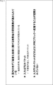
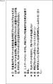
- FIG. 8 is a diagram illustrating an example of the format of a format 1 FEC block header.
- FIG. 7 is a diagram showing an example of the format of EXT byte of format 1;
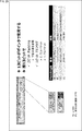
- FIG. 7 is a diagram showing an example of a padding value of format 1; It is a figure explaining simplification of illustration of a FEC block header.
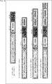
- FIG. 10 is a diagram illustrating a detailed example 1 of format 1;
- FIG. 10 is a diagram illustrating a detailed example 1 of format 1;
- FIG. 10 is a diagram illustrating a detailed example 2 of format 1;
- FIG. 10 is a diagram illustrating a detailed example 2 of format 1;
- FIG. 10 is a diagram illustrating detailed example 3 of format 1;
- FIG. 10 is a diagram illustrating detailed example 3 of format 1; It is a figure which shows the example of the format of the FEC block header of a format 2-1. It is a figure which shows the example of the padding value of form 2-1. It is a figure which shows the example of the format of the FEC block header of a form 2-2. It is a figure which shows the example of the padding value of a form 2-2.
- FIG. 18 is a diagram illustrating an example of a format of a format 3 FEC block header.
- FIG. 16 is a diagram illustrating an example of the format of EXT byte of format 3; FIG.
- FIG. 16 is a diagram illustrating an example of padding value of format 3; It is a figure which shows the example of the format of the FEC block header of a format 3-1. It is a figure which shows the example of the padding value of form 3-1.
- FIG. 18 is a diagram illustrating an example of the format of EXT byte of format 3-1.
- FIG. 20 is a diagram illustrating a detailed example 1 of the form 3-1.
- FIG. 20 is a diagram illustrating a detailed example 1 of the form 3-1.
- FIG. 20 is a diagram illustrating a detailed example 1 of the form 3-1.
- FIG. 20 is a diagram illustrating a detailed example 2 of the format 3-1.
- FIG. 20 is a diagram illustrating a detailed example 2 of the format 3-1.
- FIG. 20 is a diagram illustrating a detailed example 2 of the format 3-1.
- FIG. 20 is a diagram illustrating a detailed example 3 of the form 3-1.
- FIG. 20 is a diagram illustrating a detailed example 3 of the form 3-1.
- FIG. 18 is a diagram illustrating an example of the format of a format 4 FEC block header.
- FIG. 18 is a diagram illustrating an example of the format of EXT byte of format 4;
- FIG. 16 is a diagram illustrating an example of padding value of format 4; It is a figure which shows the example of the sending timing of time information. It is a flowchart explaining operation
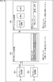
- FIG. 1 is a block diagram showing the configuration of an embodiment of a transmission system to which the present technology is applied.
- a system is a system in which a plurality of devices are logically gathered.
- the transmission system 1 includes data processing devices 10-1 to 10-N (N is an integer of 1 or more) installed in a facility associated with each broadcasting station, and a transmitting device 20 installed in a transmitting station. , Receivers 30-1 to 30-M (M is an integer of 1 or more) owned by the user.
- the data processing devices 10-1 to 10-N and the transmission device 20 are connected via communication lines 40-1 to 40-N.
- the communication lines 40-1 to 40-N can be, for example, dedicated lines.
- the data processing device 10-1 processes content such as a broadcast program produced by the broadcast station A, and transmits transmission data obtained as a result to the transmitting device 20 via the communication line 40-1.
- the data processing devices 10-2 to 10-N as in the data processing device 10-1, contents such as broadcast programs produced by the respective broadcast stations such as the broadcast station B and the broadcast station Z are processed, and the results are obtained.
- the obtained transmission data is transmitted to the transmitter 20 via the communication lines 40-2 to 40-N.
- the transmitting device 20 receives the transmission data transmitted from the data processing devices 10-1 to 10-N on the broadcast station side via the communication lines 40-1 to 40-N.
- the transmission device 20 processes transmission data from the data processing devices 10-1 to 10-N, and transmits the resulting broadcast signal from a transmission antenna installed at the transmission station.
- the broadcast signal from the transmitting device 20 on the transmitting station side is transmitted to the receiving devices 30-1 to 30-M through the broadcast transmission path 50.
- the receiving devices 30-1 to 30-M are a television receiver, a set top box (STB: Set Top Box), a recorder, a game machine, a fixed receiver such as a network storage, or a smartphone, a mobile phone, a tablet computer, etc. Mobile receiver. Also, the receiving devices 30-1 to 30-M may be, for example, on-vehicle devices mounted in a vehicle such as an on-vehicle TV, or wearable computers such as a head mounted display (HMD).
- HMD head mounted display
- the receiving device 30-1 receives and processes the broadcast signal transmitted from the transmitting device 20 through the broadcast transmission path 50, thereby reproducing the content such as the broadcast program according to the channel selection operation by the user. .
- the broadcast signal from the transmission device 20 is processed, and the content corresponding to the channel selection operation by the user is reproduced.
- the broadcast transmission path 50 is described as terrestrial waves (terrestrial broadcasts), but not limited to terrestrial waves, for example, broadcast satellites (BS: Broadcasting Satellite) or communication satellites (CS: Communications) It may be satellite broadcasting using Satellite, or cable broadcasting (CATV: Common Antenna TeleVision).
- BS Broadcasting Satellite
- CS communication satellites
- CATV Common Antenna TeleVision
- the reception devices 30-1 to 30 -M having a communication function can be connected to a communication line such as the Internet by connecting various servers. It is possible to receive various data such as contents and applications by accessing various servers and performing bi-directional communication via a communication line.
- the data processing devices 10-1 to 10-N on the broadcast station side will be referred to as the data processing device 10 unless it is necessary to distinguish them in particular.
- the receiving devices 30-1 to 30-M will be referred to as receiving devices 30 when it is not necessary to distinguish them in particular.
- FIG. 2 is a block diagram showing a configuration example of the data processing device 10 and the transmission device 20 of FIG.
- the data processing apparatus 10 includes a component processing unit 111, a signaling generation unit 112, a multiplexer 113, and a data processing unit 114.
- the component processing unit 111 processes data of components that configure content such as a broadcast program, and supplies a stream of components obtained as a result to the multiplexer 113.
- component data is, for example, data such as video, audio, subtitles, etc.
- processing such as encoding processing conforming to a predetermined encoding method is performed on these data.
- the signaling generation unit 112 generates signaling used in upper layer processing such as channel selection and reproduction of content, and supplies the signaling to the multiplexer 113. In addition, the signaling generation unit 112 generates signaling used in processing of the physical layer such as modulation and demodulation of the broadcast signal, and supplies the signaling to the data processing unit 114.
- the signaling is also referred to as control information. Also, in the following description, among signaling, signaling used in processing of the physical layer is referred to as physical layer signaling (L1 signaling), while an upper layer (Upper Layer) that is an upper layer than the physical layer (Physical Layer) The signaling used in the processing of Layer) is distinguished as upper layer signaling.
- L1 signaling physical layer signaling
- Upper Layer Upper Layer
- Physical Layer Physical Layer
- the multiplexer 113 multiplexes the stream of components supplied from the component processing unit 111 and the stream of higher layer signaling supplied from the signaling generation unit 112, and supplies the resulting stream to the data processing unit 114.
- other streams such as application and time information may be multiplexed.
- the data processing unit 114 processes the stream supplied from the multiplexer 113 to generate a packet (frame) of a predetermined format. Further, the data processing unit 114 processes packets of a predetermined format and physical layer signaling from the signaling generation unit 112 to generate transmission data, and transmits the transmission data to the transmission device 20 via the communication line 40.
- the transmission device 20 includes a data processing unit 211 and a modulation unit 212.
- the data processing unit 211 receives and processes transmission data transmitted from the data processing apparatus 10 via the communication line 40, and obtains packets (frames) of a predetermined format obtained as a result thereof, and physical layer signaling information. Extract
- the data processing unit 211 processes a packet (frame) of a predetermined format and information of physical layer signaling to obtain a frame of a physical layer conforming to a predetermined broadcast system (for example, next-generation digital terrestrial television broadcasting)
- the physical layer frame is generated and supplied to the modulation unit 212.
- the modulation unit 212 performs necessary processing (for example, modulation processing etc.) on the physical layer frame supplied from the data processing unit 211, and the broadcasting signal (RF signal) obtained as a result is installed at the transmitting station. Transmit from the transmitting antenna.
- necessary processing for example, modulation processing etc.
- RF signal broadcasting signal
- the data processing device 10 and the transmission device 20 are configured as described above.
- FIG. 3 is a block diagram showing a configuration example of the receiving device 30 of FIG.
- the receiving device 30 includes a tuner 311, a demodulation unit 312, and a data processing unit 313.
- the tuner 311 performs necessary processing on a broadcast signal (RF signal) received via the antenna 321, and supplies a signal obtained as a result to the demodulation unit 312.
- the demodulation unit 312 is configured as, for example, a demodulator such as a demodulation LSI (Large Scale Integration).
- the demodulator 312 demodulates the signal supplied from the tuner 311.
- physical layer frames are processed according to physical layer signaling to obtain packets of a predetermined format.
- the packet obtained as a result of this demodulation is supplied to the data processing unit 313.
- the data processing unit 313 is configured as, for example, a system on chip (SoC).
- SoC system on chip
- the data processing unit 313 performs predetermined processing on the packets supplied from the demodulation unit 312.
- stream decoding processing and playback processing are performed based on higher layer signaling obtained from the packet.
- Data such as video, audio, subtitles and the like obtained by the processing of the data processing unit 313 is output to the circuit of the subsequent stage.
- the receiving apparatus 30 reproduces content such as a broadcast program and outputs its video and audio.
- the receiving device 30 is configured as described above.
- the transmitting device 20 and the receiving device 30 have the following functions.
- the transmitting device 20 generates a forward error correction (FEC) block based on an input packet or an input stream, and a second generating unit generates an FEC frame based on the FEC block. , And a transmitter for transmitting the FEC frame.
- FEC forward error correction
- the header of the FEC block includes type identification information identifying the type of the input packet or input stream, and a minimum fixed length header having position information of the head of the input packet or input stream stored in the payload of the FEC frame.
- the minimum fixed length header is, in addition to the type identification information, a minimum fixed length identification that identifies whether or not the input packet length of the input packet is the minimum fixed length. It includes information and minimum input packet length as input packet length information.
- the header further includes a variable length header in addition to the minimum fixed length header.
- the variable-length header includes variable-length packet length information including upper bits of the input packet length, when the lower bits of the input packet length are the minimum input packet length information representing the minimum input packet length.
- the FEC block is generated based on the input packet or the input stream, and the FEC frame is generated and transmitted from the FEC block.
- the transmitting apparatus 20 can transmit an orthogonal frequency division multiplexing (OFDM) frame in which an FEC frame is arranged, and generates a third generation unit that generates a dummy cell for arranging time information at the beginning of the OFDM frame. It can further include.
- OFDM orthogonal frequency division multiplexing
- dummy cells can be arranged in the OFDM frame as needed, and as a result, time information can be arranged at the beginning of the OFDM frame.
- the receiving device 30 receives a signal including an FEC frame to be transmitted, a first generating unit that generates an FEC block based on the received FEC frame, and an input packet based on the FEC block. Or a second generation unit that generates an input stream.
- a signal consisting of an incoming FEC frame is received, and an FEC block is generated based on the received FEC frame. Further, based on the FEC block, an input packet or an input stream is generated.
- FIG. 4 is a diagram for explaining the background of the present technology.
- FIG. 5 is a diagram for explaining the problem solved by the present technology.
- FIG. 6 is a diagram for explaining an outline of a method for solving the problem.
- FIG. 7 is a diagram for explaining an outline of the generation of the FEC block.
- FIG. 8 is a diagram illustrating an example of the FEC block.
- FIG. 9 is a diagram illustrating a first example of baseband frame sizes.
- FIG. 10 is a diagram illustrating a second example of baseband frame sizes.
- FIG. 11 is a diagram showing a third example of baseband frame sizes.
- FIG. 12 is a diagram for describing an outline of a data format adopted in the present technology.
- FIG. 13 14, 15, 16, 17, and 18 are diagrams for explaining an example of a first format of data adopted in the present technology.
- FIG. 19 and FIG. 20 are diagrams for explaining an example of a second format of data adopted in the present technology.
- FIGS. 21, 22, 23, 24, 25, and 26 are diagrams for explaining an example of a third format of data adopted in the present technology.
- FIG. 27 is a diagram for describing an example of a fourth format of data adopted in the present technology.
- FIG. 28 is a diagram showing an example of NTP transmission timing.
- FIGS. 4 to 28 The outline of the present technology is illustrated in FIGS. 4 to 28, and the detailed contents thereof will be described below with reference to FIGS. 29 to 64.
- FIG. 29 is a diagram showing an example of the configuration of blocks involved in the generation of the FEC block.
- each block of the TLV packet generation unit 151 to the FEC frame generation unit 154 includes the data processing unit 114 (the data processing unit 114 (FIG. 2)) and the transmission device 20 (the data processing unit 211 (FIG. 2)). Included in one or the other.
- the TLV packet generation unit 151 processes an IP (Internet Protocol) stream input thereto to generate a TLV packet, and supplies the TLV packet to the FEC block generation unit 153.
- the TLV packet includes, for example, an IP packet and control information (upper layer signaling).
- the IP packet includes a UDP (User Datagram Protocol) packet.
- the TS packet processing unit 152 processes the TS stream (MPEG2-TS stream) input thereto to generate a TS packet, and supplies the TS packet to the FEC block generation unit 153.
- processing for this TS stream for example, processing such as deletion of synchronization bytes is performed.
- the TLV packet from the TLV packet generator 151 or the TS packet from the TS packet processor 152 is supplied to the FEC block generator 153.
- the FEC block generation unit 153 processes the TLV packet or TS packet to generate an FEC block, and supplies the FEC block to the FEC frame generation unit 154.
- the FEC block is composed of an FEC block header (FBH: FEC Block Header) and a data part.
- FEC block header FEC Block Header
- TLV packets or TS packets are arranged.
- TLV packets are of variable length, and TLV packets placed in one FEC block may be placed across the next FEC block.
- what is arranged in the data part of the FEC block is not limited to input packets (transmission packets) such as TLV packets and TS packets, and, for example, input streams (transmission streams) such as IP streams and TS streams are arranged. You may do so.
- the FEC frame generation unit 154 subjects the FEC block supplied from the FEC block generation unit 153 to processing such as energy diffusion, BCH (Bose-Chaudhuri-Hocquenghem) coding, LDPC (Low Density Parity Check) coding, and the like.
- the FEC frame is generated and supplied to the subsequent stage.
- the FEC frame is configured by adding the parity of the BCH code and the LDPC code to one FEC block. That is, after the variable length TLV packet is encapsulated in a fixed length FEC block, the parity of a BCH code or an LDPC code is further added, and the packet is stored in a fixed length FEC frame.
- FIG. 30 is a diagram for explaining the flow of generation of an FEC block.
- the direction of time is the direction from the left side to the right side in the figure.
- FEC block generation unit 153 when the TLV packet generated by the TLV packet generation unit 151 (FIG. 29) is input (S1), an FEC block header (FBH) is added to the TLV packet. And an FEC block is generated (S2). Then, energy diffusion is performed on the FEC block obtained in this manner (S3).
- the FEC block FB1 follows (the entire data of) two TLV packets. Part of data of one TLV packet is arranged. Also, focusing on the next FEC block FB2, in the FEC block FB2, data of one or a plurality of TLV packets following the remaining data of the TLV packet in which part of the data is arranged in the FEC block FB1. Is placed.
- the position (head position) of the first TLV packet arranged subsequent to the remaining data of a certain TLV packet (the TLV packet arranged between the FEC block FB1 and the FEC block FB2) It is desirable to ensure notification and ensure that TLV packets in the FEC block are extracted.
- a pointer (hereinafter referred to as a head TLV packet position pointer) indicating the position of the head TLV packet is disposed in the FEC block header (FBH) of the FEC block.
- the packet position pointer By the packet position pointer, the position (head position P in the figure) of the head TLV packet can be identified with certainty.
- the receiver acquires synchronization information by some cause such as reception error. If it can not, TLV packets can not be properly extracted and processed, and data may be interrupted.
- the receiver side uses the head TLV packet position pointer for each FEC block. Since the position of the leading TLV packet can be identified with certainty and the TLV packet can be always extracted and processed normally, it is possible to suppress the interruption of data.
- the number of bits allocated to the top TLV packet position pointer can be set to an arbitrary value according to the data configuration and the like. For example, since the maximum value of the leading TLV packet position pointer is determined according to the baseband frame size, the number of bits allocated to the leading TLV packet position pointer may be determined accordingly.
- FIG. 31 is a diagram for explaining the maximum value of the top TLV packet position pointer when the baseband frame size is the middle code (code length: 69120 bits).
- CR Coding Rate
- N_ldpc represents an LDPC code block (unit: bit)
- N_bch represents a BCH code block (unit: bit).
- BCH represents N_bch-K_bch (unit: bit)
- K_bch represents a BCH information block (unit: bit, byte)
- Num Bits is necessary according to K_bch (B: byte). Represents the number of bits to be
- FIG. 32 is a diagram for explaining the maximum value of the top TLV packet position pointer when the baseband frame size is a long code (code length: 276480 bits).
- code length 276480 bits.
- the meanings of CR, N_ldpc, N_bch, BCH, K_bch, and Num Bits are the same as in FIG. That is, here too, Num Bits represents the number of bits required according to K_bch (B: byte).
- the number of bits (Num Bits) is 13 when the coding rate (CR) of the LDPC code is 2/16/3/16.
- the number of bits (Num Bits) is 14 bits, 8/16, 9
- the number of bits (Num Bits) is 15 bits.
- FIG. 33 is a diagram for explaining the maximum value of the top TLV packet position pointer when the baseband frame size is a short code (code length: 17280 bits).
- code length 17280 bits.
- Num Bits represents the number of bits required according to K_bch (B: byte).
- the coding rate (CR) of the code is 3/16
- the number of bits (Num Bits) is 9 bits
- the coding rate (CR) of the LDPC code is 4/16, 5/16, 6 /.
- the number of bits (Num Bits) becomes 10 bits and becomes 8/16, 9/16, 10/16, 11/16, 12/16, 13/16, 14/16
- the number of bits (Num Bits) is 11 bits.
- FIG. 34 is a diagram illustrating an example of the format of a type 1 FEC block header.
- the 2-byte base header is composed of a 15-bit leading TLV packet position pointer and a 1-bit EXT flag.
- the leading TLV packet position pointer is a pointer that indicates the position of the leading TLV packet in the FEC block including the FEC block header in which it is arranged.
- 15 bits are secured as the top TLV packet position pointer, and therefore it can be used as a pointer for all code lengths of long code, middle code, and short code.
- the EXT flag is a flag indicating whether an extension (Extension) exists. For example, when '0' is specified as the EXT flag, it indicates that there is no extension. In this case, only a 2-byte base header is arranged as the FEC block header. On the other hand, when '1' is specified as the EXT flag, it indicates that there is an extension. In this case, the next 1 byte of the base header is the EXT byte.
- head TLV packet head TLV byte
- '0x7FFF' 111 1111 1111 1111
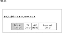
- FIG. 35 is a diagram showing an example of the format of EXT byte of type 1.
- This EXT byte is arranged as the next 1 byte of the base header of FIG. 34 when “1” is designated as the EXT flag of FIG.
- the 1-byte EXT byte includes a 2-bit padding value, a 1-bit TS flag, a 1-bit CRC flag, and a 4-bit reserved area.
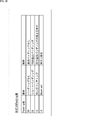
- padding value of type 1 for example, a value according to the contents shown in FIG. 36 is designated.
- '00' when '00' is specified as the padding value, it means that there is no padding. In this case there is no additional padding. Also, when '01' is specified as the padding value, it means short padding. In this case, an additional padding of 1 byte is made.
- '10' when '10' is specified as a padding value, it means long padding. In this case, two bytes would indicate the length of the additional padding.
- '11' when '11' is specified as the padding value, it means that it is a reserved area to be used in the future. Note that, as another meaning of this reserved area, for example, all padding may be designated, which means all padding.
- the TS flag is a flag indicating whether the packet arranged in the FEC block is a TS packet. For example, when '0' is specified as a TS flag, it indicates that the packet is not a TS packet. In this case, TLV packets are arranged in the FEC block. On the other hand, when '1' is designated as the TS flag, it indicates that the packet is a TS packet.
- the CRC flag is a flag indicating whether a CRC (Cyclic Redundancy Check), which is an error detection code, exists. For example, when '0' is specified as a CRC flag, it indicates that there is no CRC. On the other hand, when '1' is specified as a CRC flag, it indicates that there is a CRC. In this case, the CRC is placed immediately after the EXT byte. In addition, since it is always added when adding CRC, the first header size in the FEC block header at this time is 3 bytes.
- the reserved area is an area to be used in the future.
- FIG. 38 and 39 show a detailed example 1 of type 1.
- a configuration in which padding is added to an FEC block header consisting of a base header and an EXT byte is illustrated.
- the padding length is described as "Padding".
- a 1-bit EXT flag is arranged in the base header in addition to the 15-bit leading TLV packet position pointer, but since '1' is designated as the EXT flag, The next 1 byte of the base header is the EXT byte as an optional header.
- '00' is specified as the padding value in the first 2 bits
- '0' is specified as the TS flag in the subsequent 1 bit.
- a bit reserved in the future is placed together with a CRC flag that is '0'.
- padding of one byte (1B) is realized by the EXT byte of one byte (1B).
- '0' is specified as a TS flag in one bit following the leading two bits.
- a CRC flag of '0' and a bit reserved in the future are arranged.
- padding of 2 bytes (2 B) in total is realized by 1 byte (1 B) of EXT byte and 1 byte (1 B) of additional padding. There is.
- '0' ('00000000 00000000') is designated as the length of the additional padding of 2 bytes, so that no more padding means that padding is not added.
- '0' is specified as a TS flag in one bit following the leading two bits.
- a CRC flag of '0' and a bit reserved in the future are arranged.
- '1' ('00000000 00000001') is designated as the length of the additional padding of 2 bytes, padding of 1 byte (1 B) is further added.
- '0' is specified as a TS flag in one bit following the leading two bits.
- a CRC flag of '0' and a bit reserved in the future are arranged.
- the sum is obtained by the EXT byte of 1 byte (1 B), the additional padding length of 2 bytes (2 B), and the additional padding of 1 byte (1 B) 4 byte (4B) padding is realized.
- E of FIG. 39 “1” is designated as the EXT flag, so the next 1 byte of the base header is the EXT byte.
- EXT byte In this EXT byte, '10' is specified as the leading 2-bit padding value, so the next two bytes of the EXT byte indicate the length of the additional padding.
- '1' ('00110000 00111001') is designated as the length of the additional padding of 2 bytes, padding of 12345 bytes (12345 B) is further added.
- '0' is specified as a TS flag in one bit following the leading two bits.
- a CRC flag of '0' and a bit reserved in the future are arranged.
- 12348 bytes in total are obtained by 1 byte (1 byte) of EXT byte, 2 bytes of additional padding length, and 12345 bytes (12345 B) of additional padding. Padding of the byte (12348 B) is realized.
- FIG. 40 and FIG. 41 detailed example 2 of type 1 is shown. Also in the second detailed example, as in the first detailed example described above, the configuration in the case where padding is added to the FEC block header consisting of the base header and the EXT byte is illustrated.
- '00' is specified as the padding value in the first 2 bits
- '1' is specified as the TS flag in the subsequent 1 bit.
- the head TLV packet position pointer indicates the position (head position) of the TS packet in the FEC block.
- a bit reserved in the future is placed together with a CRC flag that is '0'.
- padding of 1 byte (1B) is realized by EXT byte of 1 byte (1B).
- '1' is specified as a TS flag in one bit following the leading two bits.
- a CRC flag of '0' and a bit reserved in the future are arranged.
- padding of 2 bytes (2 B) in total is realized by 1 byte (1 B) of EXT byte and 1 byte (1 B) of additional padding. There is.
- '0' ('00000000 00000000') is designated as the length of the additional padding of 2 bytes, so that no more padding means that padding is not added.
- '1' is specified as a TS flag in one bit following the leading two bits.
- a CRC flag of '0' and a bit reserved in the future are arranged.
- the padding of 3 bytes (3 B) in total is obtained by the length of 1 byte (1 B) of EXT byte and the length of additional padding of 2 bytes (2 B). It has been realized.
- EXT flag In D of FIG. 41, “1” is designated as the EXT flag, so the next 1 byte of the base header is the EXT byte.
- EXT byte In this EXT byte, '10' is specified as the leading 2-bit padding value, so the next two bytes of the EXT byte indicate the length of the additional padding.
- '1' ('00000000 00000001') is specified as the length of the additional padding of 2 bytes, the length of the additional padding is followed by one more byte (1 B) of Padding has been added.
- '1' is specified as a TS flag in one bit following the leading two bits.
- a CRC flag of '0' and a bit reserved in the future are arranged.
- the sum is obtained by the EXT byte of 1 byte (1 B), the additional padding length of 2 bytes (2 B), and the additional padding of 1 byte (1 B) 4 byte (4B) padding is realized.
- '00' is specified as the padding value in the first 2 bits
- '0' is specified as the TS flag in the subsequent 1 bit.
- “1” is designated as a CRC flag in the subsequent 1 bit
- a CRC of 1 byte (8 bits) is added next to the EXT byte.
- padding of 1 byte (1 B) is realized by 1 byte (1 B) of EXT byte.
- EXT flag In B of FIG. 42, “1” is designated as the EXT flag, so the next 1 byte of the base header is the EXT byte.
- EXT byte In the EXT byte, '01' is designated as the leading 2-bit padding value, and '1' is designated as the CRC flag of the subsequent bits.
- padding of 2 bytes (2 B) in total is realized by 1 byte (1 B) of EXT byte and 1 byte (1 B) of additional padding. There is.
- '0' ('00000000 00000000') is designated as the length of the additional padding of 2 bytes, so that no more padding means that padding is not added.
- the padding of 3 bytes (3 B) in total is obtained by the length of the additional padding of 1 byte (1 B) and the additional padding of 2 bytes (2 B). It has been realized.
- EXT flag In D of FIG. 43, “1” is designated as the EXT flag, so the next 1 byte of the base header is the EXT byte.
- '10' is designated as the leading 2-bit padding value
- '1' is designated as the CRC flag of the subsequent bits. Therefore, next to the EXT byte, a 1-byte CRC is added, and the next 2 bytes of this CRC indicate the length of the additional padding.
- '1' ('00000000 00000001') is designated as the length of the additional padding of 2 bytes, padding of 1 byte (1 B) is further added.
- the sum is obtained by the EXT byte of 1 byte (1 B), the additional padding length of 2 bytes (2 B), and the additional padding of 1 byte (1 B) 4 byte (4B) padding is realized.
- the configuration of the FEC block header of the first format has been described above.
- 15 bits are secured in the base header of the FEC block header in consideration of the maximum value of the first TLV packet position pointer, so the maximum number of bits (Num Bits) is 15, It is possible to cope with all code lengths of a long code which is a bit, a middle code which is 13 bits, and a short code which is 11 bits. Therefore, the configuration of the FEC block header can be extremely simplified.
- FIG. 44 is a diagram showing an example of the format of an FEC block header of type 2-1.
- a 2-byte base header is composed of an 11-bit leading TLV packet position pointer and its remaining bits (5 bits).
- the leading TLV packet position pointer is a pointer that indicates the position of the leading TLV packet in the FEC block including the FEC block header in which it is arranged.
- 11 bits are secured as the top TLV packet position pointer, so that it can be used as a short code pointer.
- the remaining 5 bits are allocated to a 2-bit padding value, a 1-bit TS flag, a 1-bit CRC flag, and a 1-bit reserved area.
- padding value for example, a value corresponding to the content shown in FIG. 45 is designated. Since the padding value of this format 2-1 is the same as the content (FIG. 36) of the padding value of format 1 described above, the description thereof is omitted here.
- the TS flag is a flag that identifies a TS packet.
- the CRC flag is a flag that indicates whether a CRC that is an error detection code is present.
- the reserved area is an area to be used in the future.
- FIG. 46 is a diagram illustrating an example of the format of the FEC block header of type 2-2.
- a 2-byte base header is composed of a 13-bit leading TLV packet position pointer and its remaining bits (3 bits).
- the leading TLV packet position pointer is a pointer that indicates the position of the leading TLV packet in the FEC block including the FEC block header in which it is arranged.
- 13 bits are secured as the top TLV packet position pointer, and therefore, they can be used as pointers for middle code and short code.
- the remaining bits of 3 bits are assigned to a padding value of 2 bits, a TS flag of 1 bit, or a CRC flag of 1 bit. That is, in the base header, although the padding value is essential, it is optional which one of the TS flag and the CRC flag is arranged.
- padding value for example, a value according to the content shown in FIG. 47 is designated.
- the padding value of this format 2-2 is the same as the content of the padding value of format 1 described above (FIG. 36), and thus the description thereof is omitted here.
- the TS flag is a flag that identifies a TS packet.
- the CRC flag is a flag that indicates whether a CRC that is an error detection code is present.
- the configuration of the FEC block header of the second format has been described above.
- 11 bits or 13 bits are secured in the base header of the FEC block header on the assumption that the long code does not exist in the target standard, so the maximum number of bits (Num Bits) It can correspond to a short code whose value is 11 bits or a middle code whose value is 13 bits. Therefore, when the long code does not exist in the target standard, the configuration of the FEC block header can be a very simplified configuration.
- FIG. 48 is a diagram showing an example of the format of a format 3 FEC block header.
- a 2-byte base header is composed of a 13-bit leading TLV packet position pointer and the remaining bits (3 bits).
- the leading TLV packet position pointer is a pointer that indicates the position of the leading TLV packet in the FEC block including the FEC block header in which it is arranged. In the format 3 base header, 13 bits are secured as the leading TLV packet position pointer.
- the remaining 3 bits are assigned to a 1-bit TS flag, a 1-bit CRC flag, and a 1-bit EXT flag.
- the details of the TS flag and the CRC flag are as described above.
- the EXT flag is a flag indicating whether or not an extension area (Extension) exists. For example, when '1' is specified as the EXT flag, the next 1 byte of the base header is the EXT byte.
- FIG. 49 shows an example of the format of the EXT byte.
- the 1-byte EXT byte is configured of 2-bit LEN_MSB, 2-bit padding value, and 4-bit reserved area.
- the 2 bits of LEN_MSB are used as 2 bits of the shortage because the maximum value of the top TLV packet position pointer becomes 15 bits in the case of a long code and the 13 bits allocated to the base header are insufficient. . In the case of a short code or a middle code, 13 bits allocated to the base header are sufficient, so 2 bits of LEN_MSB are not used.
- the use of 13 bits allocated to the base header can correspond to the maximum value (11 bits or 13 bits) of the leading TLV packet position pointer.
- the 13 bits allocated to the base header are insufficient, and the total value (15 bits) of the top TLV packet position pointer is a total of 15 bits using 2 bits of LEN_MSB. It is made to correspond.
- padding value for example, a value according to the content shown in FIG. 50 is designated. Since the padding value of this format 3 is the same as the content (FIG. 36) of the padding value of format 1 described above, the description thereof is omitted here.
- the reserved area is an area to be used in the future.
- FIG. 51 is a diagram showing an example of the format of an FEC block header of type 3-1.
- a 2-byte base header is composed of a 13-bit leading TLV packet position pointer and its remaining bits (3 bits).
- the number of bits of the first TLV packet position pointer is 13 bits in comparison with the format 3 described above, but the remaining bits of 3 bits are 2-bit padding value. And the point that it is assigned to the 1-bit EXT flag.
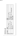
- padding value for example, a value according to the content shown in FIG. 52 is designated. Since the padding value of this format 3-1 is the same as the content (FIG. 36) of the padding value of format 1 described above, the description thereof is omitted here.
- the EXT flag is a flag indicating whether or not an extension area (Extension) exists. For example, when '1' is specified as the EXT flag, the next 1 byte of the base header is the EXT byte.
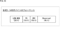
- FIG. 53 shows an example of the format of the EXT byte.
- the 1-byte EXT byte is configured of 2-bit LEN_MSB, 1-bit TS flag, 1-bit CRC flag, and 4-bit reserved area.
- LEN_MSB The 2 bits of LEN_MSB are used as 2 bits of the shortage because the maximum value of the top TLV packet position pointer becomes 15 bits in the case of a long code and the 13 bits allocated to the base header are insufficient. . In the case of the short code and the middle code, two bits of LEN_MSB are not used.
- the use of 13 bits allocated to the base header can correspond to the maximum value (11 bits or 13 bits) of the leading TLV packet position pointer.
- 13 bits of the base header and 2 bits of LEN_MSB, 15 bits in total correspond to the maximum value (15 bits) of the top TLV packet position pointer.
- the details of the TS flag and the CRC flag are as described above.
- the reserved area is an area to be used in the future.
- a 2-bit padding value and a 1-bit EXT flag are arranged in the base header in addition to the 13-bit leading TLV packet position pointer, but '00 as the padding value is disposed. There is no additional padding because 'is specified. Furthermore, since '0' is specified as the EXT flag, there is no extension of the EXT byte as an option header.
- the configuration is the case where padding is not performed.
- '01' is specified as the padding value, so the next 1 byte of the base header becomes additional 1 B padding. Since "0" is specified as the EXT flag, there is no extension of the EXT byte.
- padding of 1 byte (1B) is realized by additional padding of 1 byte (1B).
- '10' is specified as the padding value, so the next two bytes of the base header indicate the length of the additional padding.
- '0' ('00000000 00000000') is designated as the length of the additional padding of 2 bytes, so that no more padding means that padding is not added.
- padding of 2 bytes (2B) is realized by the length of additional padding of 2 bytes (2B).
- '10' is specified as the padding value, so the next two bytes of the base header indicate the length of the additional padding.
- '1' ('00000000 00000001') is specified as the length of the additional padding of 2 bytes, the length of the additional padding is followed by one more byte (1 B) of Padding has been added.
- '10' is specified as the padding value, so the next two bytes of the base header indicate the length of the additional padding.
- '2' ('00000000 0000010') is designated as the length of the additional padding of 2 bytes, following the length of the additional padding, padding of 2 bytes (2B) is performed. Has been added.
- a total padding of 4 bytes (4 B) is realized by the additional padding length of 2 bytes (2 B) and the additional padding of 2 bytes (2 B). It is done.
- the sum is obtained by the EXT byte of 1 byte (1B), the additional padding length of 2 bytes (2B), and the additional padding of 12345 bytes (12345 B). Padding of 12348 bytes (12348 B) is realized.
- a 2-bit padding value and a 1-bit EXT flag are arranged in the base header in addition to the 13-bit leading TLV packet position pointer, but '00 as the padding value is disposed. There is no additional padding because 'is specified. On the other hand, since '1' is specified as the EXT flag, the next 1 byte of the base header becomes the EXT byte as the option header.
- '1' is specified in the TS flag and the packet placed in the FEC block becomes a TS packet, so the head TLV packet position pointer is the position (head position) of the TS packet in the FEC block Is shown.
- padding of 1 byte (1B) is realized by EXT byte of 1 byte (1B).
- padding of 2 bytes (2 B) in total is realized by 1 byte (1 B) of EXT byte and 1 byte (1 B) of additional padding. There is.
- '0' ('00000000 00000000') is designated as the length of the additional padding of 2 bytes, so that no more padding means that padding is not added.
- the padding of 3 bytes (3 B) in total is obtained by the length of the 1 byte (1 B) of EXT byte and the length of the additional padding of 2 bytes (2 B). It has been realized.
- '1' ('00000000 00000001') is specified as the length of the additional padding of 2 bytes, the length of the additional padding is followed by one more byte (1 B) of Padding has been added.
- the sum is obtained by the EXT byte of 1 byte (1 B), the additional padding length of 2 bytes (2 B), and the additional padding of 1 byte (1 B) 4 byte (4B) padding is realized.
- a 2-bit padding value and a 1-bit EXT flag are arranged in the base header in addition to the 13-bit leading TLV packet position pointer, but the padding value is '00 There is no additional padding because 'is specified. On the other hand, since '1' is specified as the EXT flag, the next 1 byte of the base header becomes the EXT byte as the option header.
- padding of one byte (1B) is realized by the EXT byte of one byte (1B).
- '01' is specified as the padding value, so the next 1 byte of the CRC becomes additional 1 B padding.
- padding of 2 bytes (2 B) in total is realized by 1 byte (1 B) of EXT byte and 1 byte (1 B) of additional padding. There is.
- “1” is designated as the EXT flag, so the next 1 byte of the base header becomes the EXT byte.
- “1” is designated as the CRC flag in the 4th bit, so a CRC of 1 byte (8 bits) is added next to the EXT byte.
- '10' is specified as the padding value, so the next two bytes of the CRC indicate the length of the additional padding.
- '0' ('00000000 00000000') is designated as the length of the additional padding of 2 bytes, so that no more padding means that padding is not added.
- '10' is specified as the padding value, so the next two bytes of the CRC indicate the length of the additional padding.
- '1' ('00000000 00000001') is designated as the length of the additional padding of 2 bytes, padding of 1 byte (1 B) is added.
- the sum is obtained by the EXT byte of 1 byte (1 B), the additional padding length of 2 bytes (2 B), and the additional padding of 1 byte (1 B) 4 byte (4B) padding is realized.
- the configuration of the FEC block header of the third format has been described above.
- this third format when a long code exists in the target standard, 13 bits are secured in the base header of the FEC block header, and the maximum value of the number of bits (Num Bits) is 11 bits.
- the maximum value of the number of bits (Num Bits) is 15 bits while using the code or the middle code of 13 bits, 15 bits can be used by using 2 bits of LEN_MSB of the EXT byte.
- FIG. 61 is a diagram showing an example of the format of a type 4 FEC block header.
- the 2-byte base header is composed of a 13-bit leading TLV packet position pointer, a 1-bit TS flag, a 1-bit CRC flag, and a 1-bit EXT flag.
- the leading TLV packet position pointer is a pointer that indicates the position of the leading TLV packet in the FEC block including the FEC block header in which it is arranged.
- the remaining 3 bits are assigned to a 1-bit TS flag, a 1-bit CRC flag, and a 1-bit EXT flag.
- the details of the TS flag and the CRC flag are as described above.
- the EXT flag is a flag indicating whether or not an extension area (Extension) exists. For example, when '1' is specified as the EXT flag, the next 1 byte of the base header is the EXT byte.
- FIG. 62 shows an example of the format of the EXT byte.
- the 1-byte EXT byte is composed of 5-bit LEN_MSB, 2-bit padding value, and 1-bit reserved area.
- bit number is the bit number required according to K_bch (B: byte)
- bit in the case of K_bch bits: bit
- the number (Num Bits) is as follows.
- the maximum of the first TLV packet position pointer As described above, when using bit representation (K_bch (bits)) rather than byte representation (K_bch (B: bytes)) as the number of bits (Num Bits), the maximum of the first TLV packet position pointer The values are 18 bits, 16 bits, and 14 bits for the long code, middle code, and short code, respectively. Therefore, in the base header, 13 bits allocated to the top TLV packet position pointer are insufficient, and therefore 5 bits of LEN_MSB are used as the insufficient bits.
- the leading TLV packet position pointer can be expressed in bits.
- padding value for example, a value according to the content shown in FIG. 63 is designated. Since the padding value of this format 4 is the same as the content (FIG. 36) of the padding value of format 1 described above, the description thereof is omitted here.
- the reserved area is an area to be used in the future.
- the configuration of the FEC block header of the fourth format has been described above.
- this fourth format when a long code exists in the target standard, 18 bits are secured by the base header (13 bits) of the FEC block header and LEN_MSB (5 bits) of the EXT byte, and the number of bits
- the maximum value of (Num Bits) can correspond to a short code of 14 bits, a middle code of 16 bits, and a long code of 18 bits. Therefore, when the long code exists in the standard, the leading TLV packet position pointer can be expressed in bits.
- Frequency Division Multiplexing (FDM) is adopted as a method of multiplexing broadcast signals. It is assumed that frequency division multiplexing (FDM) is adopted in the next generation of digital terrestrial television broadcasting as well.
- a predetermined frequency band for example, 6 MHz
- a predetermined frequency band for example, 6 MHz
- hierarchical transmission using a band for each one or a plurality of segments is performed.
- data of different services can be transmitted, for example, in each hierarchy made of frequency bands of one or more segments obtained by frequency division.
- each hierarchy is a unit that combines one or more segments.
- an OFDM segment is used.
- OFDM Orthogonal Frequency Division Multiplexing
- subcarriers orthogonal subcarriers
- digital modulation is performed.
- the hierarchy can also be conceptualized as PLP (Physical Layer Pipe).
- PLP Physical Layer Pipe
- M-PLP Multiple-PLP
- time information for achieving synchronization between the transmission side and the reception side is transmitted, and synchronization is achieved between the transmission device 20 on the transmission side and the reception device 30 on the reception side.
- FIG. 64 is a diagram illustrating an example of transmission timing of time information.
- FIG. 64 data to be processed by the transmission device 20 is schematically represented on the upper side, and data to be processed by the reception device 30 is schematically represented on the lower side.
- the horizontal direction represents time, and the direction is from the left side to the right side in the drawing.
- the transmission apparatus 20 performs necessary processing on the TLV packet to obtain an FEC frame including an FEC block to which the BCH code and the LDPC code are added. Also, in the transmitting apparatus 20, a physical layer frame (hereinafter referred to as an ISDB-T2 frame) can be obtained by performing necessary processing on the FEC frame.
- an ISDB-T2 frame a physical layer frame
- the TLV packet is a variable-length packet, for example, 4 to 65,536 bytes in size.
- the TLV packet is represented by "Data” in the figure.
- NTP time information which is time information in NTP (Network Time Protocol) format is represented by “NTP” in the drawing.
- the FEC frame includes an FEC block to which a BCH code and an LDPC code are added.
- One ISDB-T2 frame is configured by k + 1 FEC frames of the FEC frame # 0 to the FEC frame #k.
- an FEC block header (FBH) is added, and if padding is inserted, an additional padding of predetermined bytes is performed following the FEC block header (FBH).
- the FEC block header includes the top TLV packet position pointer.
- the top TLV packet position pointer included in the FEC block header (FBH) added to the top of the FEC frame # 1 is the data # 1 of Data # 2 arranged following Data # 1-2 in the FEC frame # 1. It represents the start position.
- the OFDM symbol is represented by "Symbol" in the figure.
- One ISDB-T2 frame is configured by n + 1 OFDM symbols of Symbol # 0 to Symbol # n. That is, it can be said that this ISDB-T2 frame is an OFDM frame which is a unit for transmitting data.
- FDM frequency division multiplexing
- the OFDM symbol is further divided into segments.
- the segment is represented by "Seg" in the figure.
- One OFDM symbol is configured by m + 1 segments of Seg # 0 to Seg # m.
- the NTP time information is inserted so as to be the head of the ISDB-T2 frame (strictly, the FEC block header in which the NTP time information is added to the FEC frame # 0 at the head Inserted following the FBH)).
- the NTP time information includes the time at the beginning of the ISDB-T2 frame as the information of the time defined by the NTP.
- NTP time information is not necessarily placed at the beginning of the ISDB-T2 frame.
- a dummy cell D is inserted following the last FEC frame #k constituting an ISDB-T2 frame, and the head of the next ISDB-T2 frame (head of FEC frame # 0) , NTP time information can be inserted.
- the dummy cell D is generated by the dummy cell generation unit 161 as needed, and the OFDM frame is arranged. It is placed in the frame.
- the NTP time information is linked to the frame length of the ISDB-T2 frame as an OFDM frame.
- NTP time information indicating the time at the beginning of the ISDB-T2 frame is inserted at the beginning of the ISDB-T2 frame, but ISDB-T2
- the boundary may or may not be coincident between the frame and the FEC frame.
- the insertion position of the NTP time information is a position shifted from the head of the ISDB-T2 frame, so that the dummy cell D is inserted, and the NTP time information is ISDB- Make it inserted at the beginning of the T2 frame.
- a TLV packet is obtained by performing necessary processing on the ISDB-T2 frame.
- NTP time information arranged at the head thereof can be obtained.
- the NTP time information indicates the time at the beginning of the ISDB-T2 frame.
- the receiving apparatus 30 since the boundaries of the ISDB-T2 frame and the TLV packet coincide with each other, the time at the beginning of the ISDB-T2 frame indicated by the NTP time information inserted at the beginning of the ISDB-T2 frame is referred to. Clock recovery can be performed.
- clock synchronization based on NTP time information is realized between the transmitting device 20 on the transmitting side and the receiving device 30 on the receiving side, and in the receiving device 30, each NTP time information included at the head of the ISDB-T2 frame It is possible to process a plurality of TLV packets (Data # 0 to Data # z).
- steps S11 to S13 of FIG. 65 are executed by, for example, the data processing unit 211 or the modulation unit 212 of the transmission device 20 (FIG. 2).
- the processes in steps S31 to S33 in FIG. 65 are performed by, for example, the demodulation unit 312 or the data processing unit 313 in the receiving device 30 (FIG. 3).
- step S11 the FEC block generation unit 153 processes the TLV packet input thereto to generate an FEC block.
- an FEC block header (FBH) including a TLV packet position pointer, a TS flag, and a CRC flag is inserted.
- step S12 the FEC frame generation unit 154 processes the FEC block generated in the process of step S11, and generates an FEC frame.
- step S13 the modulator 212 processes the FEC frame generated in the process of step S12, and transmits a signal obtained from the FEC frame.
- the signal transmitted from the transmitting apparatus 20 on the transmitting side is received by the receiving apparatus 30 on the receiving side.
- step S31 the tuner 311 receives a signal obtained from the FEC frame.
- step S32 the demodulation unit 312 processes the signal received in the process of step S31 and generates an FEC block.
- step S33 the data processing unit 313 processes the FEC block generated in the process of step S32 to generate a TLV packet.
- an FEC block header (FBH) including a TLV packet position pointer, a TS flag, and a CRC flag is inserted.
- the position of the leading TLV packet in the FEC block can be identified with certainty by the TLV packet position pointer, and the TLV packet can be extracted from the FEC block.
- the TLV packet obtained in this manner is further processed by (the data processing unit 313 or the processing unit of the latter stage) of the receiving device 30 on the receiving side, and content such as a broadcast program is reproduced.
- BS broadcast satellites
- CS communication satellites
- CATV cable television
- the TLV packet is an example of a transmission packet
- the transmission packet includes, for example, ALP (ATSC Link-Layer Protocol) packet or GSE (Generic Stream Encapsulation) packet, which is a variable-length packet.
- ALP ATSC Link-Layer Protocol
- GSE Generic Stream Encapsulation
- a frame and a packet may be used by the same meaning.
- time information defined by NTP is used as the time information
- the present invention is not limited thereto, for example, defined by PTP (Precision Time Protocol) or 3GPP (Third Generation Partnership Project) It is possible to use information of any time such as information of a certain time, information of a time included in GPS (Global Positioning System) information, and other information of a time determined in a uniquely determined format.
- PTP Precision Time Protocol
- 3GPP Third Generation Partnership Project
- the present technology is a predetermined standard that is defined on the assumption that a transmission line other than a broadcast network, ie, a communication line (communication network) such as the Internet or a telephone network, is used as a transmission line.
- a communication line such as the Internet is used as a transmission line of the transmission system 1 (FIG. 1), and the functions of the data processing device 10 and the transmission device 20 are provided by a communication server provided on the Internet. . Then, the communication server and the receiving device 30 perform bi-directional communication via the communication line.
- FIG. 66 is a diagram showing an example of a hardware configuration of a computer that executes the series of processes described above according to a program.
- a central processing unit (CPU) 1001, a read only memory (ROM) 1002, and a random access memory (RAM) 1003 are mutually connected by a bus 1004.
- An input / output interface 1005 is further connected to the bus 1004.
- An input unit 1006, an output unit 1007, a recording unit 1008, a communication unit 1009, and a drive 1010 are connected to the input / output interface 1005.
- the input unit 1006 includes a keyboard, a mouse, a microphone and the like.
- the output unit 1007 includes a display, a speaker, and the like.
- the recording unit 1008 includes a hard disk, a non-volatile memory, and the like.
- the communication unit 1009 includes a network interface or the like.
- the drive 1010 drives a removable recording medium 1011 such as a magnetic disk, an optical disk, a magneto-optical disk, or a semiconductor memory.
- the CPU 1001 loads the program stored in the ROM 1002 or the recording unit 1008 into the RAM 1003 via the input / output interface 1005 and the bus 1004, and executes the program. A series of processing is performed.
- the program executed by the computer 1000 can be provided by being recorded on, for example, a removable recording medium 1011 as a package medium or the like. Also, the program can be provided via a wired or wireless transmission medium such as a local area network, the Internet, or digital satellite broadcasting.
- the program can be installed in the recording unit 1008 via the input / output interface 1005 by attaching the removable recording medium 1011 to the drive 1010. Also, the program can be received by the communication unit 1009 via a wired or wireless transmission medium and installed in the recording unit 1008. In addition, the program can be installed in advance in the ROM 1002 or the recording unit 1008.
- the processing performed by the computer according to the program does not necessarily have to be performed chronologically in the order described as the flowchart. That is, the processing performed by the computer according to the program includes processing executed in parallel or separately (for example, parallel processing or processing by an object). Further, the program may be processed by one computer (processor) or may be distributed and processed by a plurality of computers.
- the present technology can have the following configurations.
- a first generation unit that generates a Forward Error Correction (FEC) block based on an input packet or an input stream;
- a second generation unit that generates an FEC frame based on the FEC block;
- a transmitter configured to transmit the FEC frame;
- the header of the FEC block includes type identification information for identifying the type of the input packet or the input stream, information for detecting an error in the header, and the input packet or the input stream stored in the payload of the FEC frame. Transmitting device including a minimum fixed length header with leading position information.
- the type identification information is a TLV (Type Length Value) packet
- the minimum fixed length header identifies, in addition to the type identification information, whether or not the input packet length of the input packet is a minimum fixed length.
- the transmission apparatus including minimum fixed length identification information and a minimum input packet length as information of the input packet length.
- the header further includes a variable length header in addition to the minimum fixed length header,
- the variable-length header includes variable-length packet length information including upper bits of the input packet length, where lower bits of the input packet length are set as minimum input packet length information representing the minimum input packet length.
- the transmitter according to the above.
- the apparatus according to any one of (1) to (3), further including: a third generation unit that generates a dummy cell for placing time information at the beginning of an OFDM (Orthogonal Frequency Division Multiplexing) frame in which the FEC frame is placed. Transmitter.
- OFDM Orthogonal Frequency Division Multiplexing
- the header of the FEC block includes type identification information for identifying the type of the input packet or the input stream, information for detecting an error in the header, and the input packet or the input stream stored in the payload of the FEC frame.
- a transmission method including a minimum fixed length header having position information at the beginning of a packet.
- the header of the FEC block is a minimum fixed length including type identification information identifying the type of the input packet or the input stream, and position information of the head of the input packet or the input stream stored in the payload of the FEC frame Receiver containing header.
- the type identification information is a TLV packet
- the minimum fixed length header is, in addition to the type identification information, minimum fixed length identification information for identifying whether or not the input packet length of the input packet is the minimum fixed length. And a minimum input packet length as information of the input packet length.
- the header further includes a variable length header in addition to the minimum fixed length header,
- the variable-length header includes variable-length packet length information including upper bits of the input packet length, where lower bits of the input packet length are set as minimum input packet length information representing the minimum input packet length.
- time information is arranged at the head by inserting a dummy cell, and the reception device according to any one of (6) to (8).
- the header of the FEC block is a minimum fixed length including type identification information identifying the type of the input packet or the input stream, and position information of the head of the input packet or the input stream stored in the payload of the FEC frame Receive method including header.
- Reference Signs List 1 transmission system 10, 10-1 to 10-N data processing apparatus, 20 transmitting apparatus, 30, 30-1 to 30-M receiving apparatus, 40, 40-1 to 40-N communication line, 50 broadcast transmission line, 111 component processing unit, 112 signaling generation unit, 113 multiplexer, 114 data processing unit, 151 TLV packet generation unit, 152 TS packet processing unit, 153 FEC block generation unit, 154 FEC frame generation unit, 161 dummy cell generation unit, 211 data processing Unit, 212 modulator, 311 tuner, 312 demodulator, 313 data processor
Landscapes
- Engineering & Computer Science (AREA)
- Multimedia (AREA)
- Signal Processing (AREA)
- Computer Networks & Wireless Communication (AREA)
- Quality & Reliability (AREA)
- Detection And Prevention Of Errors In Transmission (AREA)
- Communication Control (AREA)
- Data Exchanges In Wide-Area Networks (AREA)
Abstract
Description
2.本技術の概要
3.本技術の詳細な内容
(3-1)第1の形式
(3-2)第2の形式
(3-3)第3の形式
(3-4)第4の形式
4.本技術の時刻情報の送出タイミング
5.送信側と受信側の動作
6.変形例
7.コンピュータの構成
図1は、本技術を適用した伝送システムの一実施の形態の構成を示すブロック図である。なお、システムとは、複数の装置が論理的に集合したものをいう。
図2は、図1のデータ処理装置10と送信装置20の構成例を示すブロック図である。
図3は、図1の受信装置30の構成例を示すブロック図である。
図5は、本技術が解決する問題を説明する図である。
図6は、問題を解決する方法の概要を説明する図である。
図7は、FECブロックの生成の概要を説明する図である。
図8は、FECブロックの例を示す図である。
図9は、ベースバンドフレームのサイズの第1の例を示す図である。
図10は、ベースバンドフレームのサイズの第2の例を示す図である。
図11は、ベースバンドフレームのサイズの第3の例を示す図である。
図12は、本技術で採用するデータの形式の概要を説明する図である。
図13、図14、図15、図16、図17、及び、図18は、本技術で採用するデータの第1の形式の例を説明する図である。
図19及び図20は、本技術で採用するデータの第2の形式の例を説明する図である。
図21、図22、図23、図24、図25、及び、図26は、本技術で採用するデータの第3の形式の例を説明する図である。
図27は、本技術で採用するデータの第4の形式の例を説明する図である。
図28は、NTPの送出タイミングの例を示す図である。
図29は、FECブロックの生成に関わるブロックの構成の例を示す図である。
図30は、FECブロックの生成の流れを説明する図である。なお、図30において、時間の方向は、図中の左側から右側に向かう方向とされる。
図31は、ベースバンドフレームサイズが、ミドル符号(符号長:69120ビット)の場合の先頭TLVパケット位置ポインタの最大値を説明する図である。
まず、図34乃至図43を参照して、第1の形式(以下、形式1とも記述する)のFECブロックヘッダ(FBH)の構成について説明する。
図34は、形式1のFECブロックヘッダのフォーマットの例を示す図である。
図35は、形式1のEXTバイトのフォーマットの例を示す図である。
図38及び図39には、形式1の詳細例1を示している。この詳細例1では、ベースヘッダとEXTバイトからなるFECブロックヘッダに対し、パッディングを追加した場合の構成を図示している。なお、この詳細例においては、パッディングの長さを、「Padding」と記述している。
図38のAは、パッディングの長さが1バイト(1B)となる場合に、EXTフラグ = '1'と、TSフラグ = '0'がそれぞれ指定された場合のFECブロックヘッダの構成を示している。
図38のBは、パッディングの長さが2バイト(2B)となる場合に、EXTフラグ = '1'と、TSフラグ = '0'がそれぞれ指定された場合のFECブロックヘッダの構成を示している。
図38のCは、パッディングの長さが3バイト(3B)となる場合に、EXTフラグ = '1'と、TSフラグ = '0'がそれぞれ指定された場合のFECブロックヘッダの構成を示している。
図39のDは、パッディングの長さが4バイト(4B)となる場合に、EXTフラグ = '1'と、TSフラグ = '0'がそれぞれ指定された場合のFECブロックヘッダの構成を示している。
図39のEは、パッディングの長さが12348バイト(12348B)となる場合に、EXTフラグ = '1'と、TSフラグ = '0'がそれぞれ指定された場合のFECブロックヘッダの構成を示している。
図40及び図41には、形式1の詳細例2を示している。この詳細例2においても、上述した詳細例1と同様に、ベースヘッダとEXTバイトからなるFECブロックヘッダに対し、パッディングを追加した場合の構成を図示している。
図40のAは、パッディングの長さが1バイト(1B)となる場合に、EXTフラグ = '1'と、TSフラグ = '1'がそれぞれ指定された場合のFECブロックヘッダの構成を示している。
図40のBは、パッディングの長さが2バイト(2B)となる場合に、EXTフラグ = '1'と、TSフラグ = '1'がそれぞれ指定された場合のFECブロックヘッダの構成を示している。
図40のCは、パッディングの長さが3バイト(3B)となる場合に、EXTフラグ = '1'と、TSフラグ = '1'がそれぞれ指定された場合のFECブロックヘッダの構成を示している。
図41のDは、パッディングの長さが4バイト(4B)となる場合に、EXTフラグ = '1'と、TSフラグ = '1'がそれぞれ指定された場合のFECブロックヘッダの構成を示している。
図42及び図43には、形式1の詳細例3を示している。この詳細例3においては、ベースヘッダとEXTバイトとCRCからなるFECブロックヘッダに対し、パッディングを追加した場合の構成を図示している。
図42のAは、パッディングの長さが1バイト(1B)となる場合に、EXTフラグ = '1'と、CRCフラグ = '1'がそれぞれ指定された場合のFECブロックヘッダの構成を示している。
図42のBは、パッディングの長さが2バイト(2B)となる場合に、EXTフラグ = '1'と、CRCフラグ = '1'がそれぞれ指定された場合のFECブロックヘッダの構成を示している。
図42のCは、パッディングの長さが3バイト(3B)となる場合に、EXTフラグ = '1'と、CRCフラグ = '1'がそれぞれ指定された場合のFECブロックヘッダの構成を示している。
図43のDは、パッディングの長さが4バイト(4B)となる場合に、EXTフラグ = '1'と、CRCフラグ = '1'がそれぞれ指定された場合のFECブロックヘッダの構成を示している。
次に、図44乃至図47を参照して、第2の形式(以下、形式2とも記述する)のFECブロックヘッダ(FBH)の構成について説明する。
図44は、形式2-1のFECブロックヘッダのフォーマットの例を示す図である。
図46は、形式2-2のFECブロックヘッダのフォーマットの例を示す図である。
次に、図48乃至図60を参照して、第3の形式(以下、形式3とも記述する)のFECブロックヘッダ(FBH)の構成について説明する。
図48は、形式3のFECブロックヘッダのフォーマットの例を示す図である。
図51は、形式3-1のFECブロックヘッダのフォーマットの例を示す図である。
図54乃至図56には、形式3-1の詳細例1を示している。この詳細例1では、ベースヘッダからなるFECブロックヘッダに対し、パッディングを追加した場合の構成を図示している。
図54のAは、パッディングがない場合に、EXTフラグ = '0'が指定された場合のFECブロックヘッダの構成を示している。
図54のBは、パッディングの長さが1バイト(1B)となる場合に、EXTフラグ = '0'が指定された場合のFECブロックヘッダの構成を示している。
図54のCは、パッディングの長さが2バイト(2B)となる場合に、EXTフラグ = '0'が指定された場合のFECブロックヘッダの構成を示している。
図55のDは、パッディングの長さが3バイト(3B)となる場合に、EXTフラグ = '0'が指定された場合のFECブロックヘッダの構成を示している。
図55のEは、パッディングの長さが4バイト(4B)となる場合に、EXTフラグ = '0'が指定された場合のFECブロックヘッダの構成を示している。
図56のFは、パッディングの長さが12348バイト(12348B)となる場合に、EXTフラグ = '1'が指定された場合のFECブロックヘッダの構成を示している。
図57及び図58には、形式3-1の詳細例2を示している。この詳細例2では、ベースヘッダとEXTバイトからなるFECブロックヘッダに対し、パッディングを追加した場合の構成を図示している。
図57のAは、パッディングの長さが1バイト(1B)となる場合に、EXTフラグ = '1'が指定された場合のFECブロックヘッダの構成を示している。
図57のBは、パッディングの長さが2バイト(2B)となる場合に、EXTフラグ = '1'が指定された場合のFECブロックヘッダの構成を示している。
図57のCは、パッディングの長さが3バイト(3B)となる場合に、EXTフラグ = '1'が指定された場合のFECブロックヘッダの構成を示している。
図58のDは、パッディングの長さが4バイト(4B)となる場合に、EXTフラグ = '1'が指定された場合のFECブロックヘッダの構成を示している。
図59及び図60には、形式3-1の詳細例3を示している。この詳細例3では、ベースヘッダとEXTバイトとCRCからなるFECブロックヘッダに対し、パッディングを追加した場合の構成を図示している。
図59のAは、パッディングの長さが1バイト(1B)となる場合に、EXTフラグ = '1'と、CRCフラグ = '1'がそれぞれ指定された場合のFECブロックヘッダの構成を示している。
図59のBは、パッディングの長さが2バイト(2B)となる場合に、EXTフラグ = '1'と、CRCフラグ = '1'がそれぞれ指定された場合のFECブロックヘッダの構成を示している。
図59のCは、パッディングの長さが3バイト(3B)となる場合に、EXTフラグ = '1'と、CRCフラグ = '1'がそれぞれ指定された場合のFECブロックヘッダの構成を示している。
図60のDは、パッディングの長さが4バイト(4B)となる場合に、EXTフラグ = '1'と、CRCフラグ = '1'がそれぞれ指定された場合のFECブロックヘッダの構成を示している。
最後に、図61乃至図63を参照して、第4の形式(以下、形式4とも記述する)のFECブロックヘッダ(FBH)の構成について説明する。
図61は、形式4のFECブロックヘッダのフォーマットの例を示す図である。
上述した説明では、デジタルテレビ放送の規格として、日本等で採用されている方式であるISDB(Integrated Services Digital Broadcasting)を中心に説明したが、本技術は、米国等が採用する方式であるATSC(Advanced Television Systems Committee)や、欧州の各国等が採用する方式であるDVB(Digital Video Broadcasting)などに適用するようにしてもよい。
また、上述したパケットやフレーム、シグナリング(制御情報)などの名称は、一例であって、他の名称が用いられる場合がある。ただし、これらの名称の違いは、形式的な違いであって、対象のパケットやフレーム、シグナリングなどの実質的な内容が異なるものではない。
上述した説明では、時刻情報として、NTPで規定される時刻の情報が用いられる場合を説明したが、それに限らず、例えば、PTP(Precision Time Protocol)や3GPP(Third Generation Partnership Project)で規定されている時刻の情報や、GPS(Global Positioning System)情報に含まれる時刻の情報、その他独自に決定された形式の時刻の情報等の任意の時刻の情報を用いることができる。
また、本技術は、伝送路として、放送網以外の伝送路、すなわち、例えば、インターネットや電話網等の通信回線(通信網)などを利用することを想定して規定されている所定の規格(デジタル放送の規格以外の規格)などにも適用することができる。その場合には、伝送システム1(図1)の伝送路として、インターネット等の通信回線が利用され、データ処理装置10や送信装置20の機能は、インターネット上に設けられた通信サーバにより提供される。そして、当該通信サーバと、受信装置30とが、通信回線を介して双方向の通信を行うことになる。
入力パケット又は入力ストリームに基づいて、FEC(Forward Error Correction)ブロックを生成する第1の生成部と、
前記FECブロックに基づいて、FECフレームを生成する第2の生成部と、
前記FECフレームを送信する送信部と
を含み、
前記FECブロックのヘッダは、前記入力パケット又は前記入力ストリームの種別を識別する種別識別情報と、ヘッダのエラーを検出する情報と、前記FECフレームのペイロードに格納される前記入力パケット又は前記入力ストリームの先頭の位置情報を有する最小固定長ヘッダを含む
送信装置。
(2)
前記種別識別情報がTLV(Type Length Value)パケットである場合、前記最小固定長ヘッダは、前記種別識別情報に加えて、前記入力パケットの入力パケット長が最小固定長であるか否かを識別する最小固定長識別情報、及び前記入力パケット長の情報としての最小入力パケット長を含む
前記(1)に記載の送信装置。
(3)
前記最小固定長識別情報が、前記入力パケット長が前記最小固定長ではないことを示す場合、前記ヘッダは、前記最小固定長ヘッダに加えて、さらに、可変長ヘッダを含み、
前記可変長ヘッダは、前記入力パケット長の下位ビットを、前記最小入力パケット長を表す最小入力パケット長情報とするとき、前記入力パケット長の上位ビットからなる可変長パケット長情報を含む
前記(2)に記載の送信装置。
(4)
前記FECフレームが配置されるOFDM(Orthogonal Frequency Division Multiplexing)フレームの先頭に時刻情報を配置するためのダミーセルを生成する第3の生成部をさらに含む
前記(1)乃至(3)のいずれかに記載の送信装置。
(5)
入力パケット又は入力ストリームに基づいて、FECブロックを生成することと、
前記FECブロックに基づいて、FECフレームを生成することと、
前記FECフレームを送信することと
を含み、
前記FECブロックのヘッダは、前記入力パケット又は前記入力ストリームの種別を識別する種別識別情報と、ヘッダのエラーを検出する情報と、前記FECフレームのペイロードに格納される前記入力パケット又は前記入力ストリームのパケット先頭の位置情報を有する最小固定長ヘッダを含む
送信方法。
(6)
送信されてくるFECフレームからなる信号を受信する受信部と、
受信された前記FECフレームに基づいて、FECブロックを生成する第1の生成部と、
前記FECブロックに基づいて、入力パケット又は入力ストリームを生成する第2の生成部と
を含み、
前記FECブロックのヘッダは、前記入力パケット又は前記入力ストリームの種別を識別する種別識別情報と、前記FECフレームのペイロードに格納される前記入力パケット又は前記入力ストリームの先頭の位置情報を有する最小固定長ヘッダを含む
受信装置。
(7)
前記種別識別情報がTLVパケットである場合、前記最小固定長ヘッダは、前記種別識別情報に加えて、前記入力パケットの入力パケット長が最小固定長であるか否かを識別する最小固定長識別情報、及び前記入力パケット長の情報としての最小入力パケット長を含む
前記(6)に記載の受信装置。
(8)
前記最小固定長識別情報が、前記入力パケット長が前記最小固定長ではないことを示す場合、前記ヘッダは、前記最小固定長ヘッダに加えて、さらに、可変長ヘッダを含み、
前記可変長ヘッダは、前記入力パケット長の下位ビットを、前記最小入力パケット長を表す最小入力パケット長情報とするとき、前記入力パケット長の上位ビットからなる可変長パケット長情報を含む
前記(7)に記載の受信装置
(9)
前記FECフレームが配置されるOFDMフレームでは、ダミーセルを挿入することで、その先頭に時刻情報が配置される
前記(6)乃至(8)のいずれかに記載の受信装置。
(10)
送信されてくるFECフレームからなる信号を受信することと、
受信された前記FECフレームに基づいて、FECブロックを生成することと、
前記FECブロックに基づいて、入力パケット又は入力ストリームを生成することと
を含み、
前記FECブロックのヘッダは、前記入力パケット又は前記入力ストリームの種別を識別する種別識別情報と、前記FECフレームのペイロードに格納される前記入力パケット又は前記入力ストリームの先頭の位置情報を有する最小固定長ヘッダを含む
受信方法。
Claims (10)
- 入力パケット又は入力ストリームに基づいて、FEC(Forward Error Correction)ブロックを生成する第1の生成部と、
前記FECブロックに基づいて、FECフレームを生成する第2の生成部と、
前記FECフレームを送信する送信部と
を含み、
前記FECブロックのヘッダは、前記入力パケット又は前記入力ストリームの種別を識別する種別識別情報と、ヘッダのエラーを検出する情報と、前記FECフレームのペイロードに格納される前記入力パケット又は前記入力ストリームの先頭の位置情報を有する最小固定長ヘッダを含む
送信装置。 - 前記種別識別情報がTLV(Type Length Value)パケットである場合、前記最小固定長ヘッダは、前記種別識別情報に加えて、前記入力パケットの入力パケット長が最小固定長であるか否かを識別する最小固定長識別情報、及び前記入力パケット長の情報としての最小入力パケット長を含む
請求項1に記載の送信装置。 - 前記最小固定長識別情報が、前記入力パケット長が前記最小固定長ではないことを示す場合、前記ヘッダは、前記最小固定長ヘッダに加えて、さらに、可変長ヘッダを含み、
前記可変長ヘッダは、前記入力パケット長の下位ビットを、前記最小入力パケット長を表す最小入力パケット長情報とするとき、前記入力パケット長の上位ビットからなる可変長パケット長情報を含む
請求項2に記載の送信装置。 - 前記FECフレームが配置されるOFDM(Orthogonal Frequency Division Multiplexing)フレームの先頭に時刻情報を配置するためのダミーセルを生成する第3の生成部をさらに含む
請求項1に記載の送信装置。 - 入力パケット又は入力ストリームに基づいて、FECブロックを生成することと、
前記FECブロックに基づいて、FECフレームを生成することと、
前記FECフレームを送信することと
を含み、
前記FECブロックのヘッダは、前記入力パケット又は前記入力ストリームの種別を識別する種別識別情報と、ヘッダのエラーを検出する情報と、前記FECフレームのペイロードに格納される前記入力パケット又は前記入力ストリームのパケット先頭の位置情報を有する最小固定長ヘッダを含む
送信方法。 - 送信されてくるFECフレームからなる信号を受信する受信部と、
受信された前記FECフレームに基づいて、FECブロックを生成する第1の生成部と、
前記FECブロックに基づいて、入力パケット又は入力ストリームを生成する第2の生成部と
を含み、
前記FECブロックのヘッダは、前記入力パケット又は前記入力ストリームの種別を識別する種別識別情報と、前記FECフレームのペイロードに格納される前記入力パケット又は前記入力ストリームの先頭の位置情報を有する最小固定長ヘッダを含む
受信装置。 - 前記種別識別情報がTLVパケットである場合、前記最小固定長ヘッダは、前記種別識別情報に加えて、前記入力パケットの入力パケット長が最小固定長であるか否かを識別する最小固定長識別情報、及び前記入力パケット長の情報としての最小入力パケット長を含む
請求項6に記載の受信装置。 - 前記最小固定長識別情報が、前記入力パケット長が前記最小固定長ではないことを示す場合、前記ヘッダは、前記最小固定長ヘッダに加えて、さらに、可変長ヘッダを含み、
前記可変長ヘッダは、前記入力パケット長の下位ビットを、前記最小入力パケット長を表す最小入力パケット長情報とするとき、前記入力パケット長の上位ビットからなる可変長パケット長情報を含む
請求項7に記載の受信装置 - 前記FECフレームが配置されるOFDMフレームでは、ダミーセルを挿入することで、その先頭に時刻情報が配置される
請求項6に記載の受信装置。 - 送信されてくるFECフレームからなる信号を受信することと、
受信された前記FECフレームに基づいて、FECブロックを生成することと、
前記FECブロックに基づいて、入力パケット又は入力ストリームを生成することと
を含み、
前記FECブロックのヘッダは、前記入力パケット又は前記入力ストリームの種別を識別する種別識別情報と、前記FECフレームのペイロードに格納される前記入力パケット又は前記入力ストリームの先頭の位置情報を有する最小固定長ヘッダを含む
受信方法。
Priority Applications (6)
| Application Number | Priority Date | Filing Date | Title |
|---|---|---|---|
| KR1020237002458A KR20230019987A (ko) | 2016-12-16 | 2017-12-01 | 송신 장치, 송신 방법, 수신 장치, 및 수신 방법 |
| EP17881865.4A EP3557792A4 (en) | 2016-12-16 | 2017-12-01 | SENDING DEVICE, TRANSMISSION PROCEDURE, RECEPTION DEVICE AND RECEPTION PROCEDURE |
| BR112019011500-5A BR112019011500A2 (pt) | 2016-12-16 | 2017-12-01 | aparelho e método de transmissão, e, aparelho e método de recepção. |
| KR1020197015972A KR20190092415A (ko) | 2016-12-16 | 2017-12-01 | 송신 장치, 송신 방법, 수신 장치, 및 수신 방법 |
| US16/346,351 US11005594B2 (en) | 2016-12-16 | 2017-12-01 | Transmission apparatus, transmission method, reception apparatus, and reception method for forward error correction frame |
| PH12019501313A PH12019501313A1 (en) | 2016-12-16 | 2019-06-10 | Transmission device, transmission method, reception device, and method |
Applications Claiming Priority (4)
| Application Number | Priority Date | Filing Date | Title |
|---|---|---|---|
| JP2016244528 | 2016-12-16 | ||
| JP2016-244528 | 2016-12-16 | ||
| JP2017015418A JP7069542B2 (ja) | 2016-12-16 | 2017-01-31 | 送信装置、及び、送信方法 |
| JP2017-015418 | 2017-07-18 |
Publications (1)
| Publication Number | Publication Date |
|---|---|
| WO2018110315A1 true WO2018110315A1 (ja) | 2018-06-21 |
Family
ID=62558288
Family Applications (1)
| Application Number | Title | Priority Date | Filing Date |
|---|---|---|---|
| PCT/JP2017/043236 Ceased WO2018110315A1 (ja) | 2016-12-16 | 2017-12-01 | 送信装置、送信方法、受信装置、及び、受信方法 |
Country Status (3)
| Country | Link |
|---|---|
| JP (2) | JP7347580B2 (ja) |
| KR (1) | KR20230019987A (ja) |
| WO (1) | WO2018110315A1 (ja) |
Cited By (1)
| Publication number | Priority date | Publication date | Assignee | Title |
|---|---|---|---|---|
| WO2021054179A1 (ja) * | 2019-09-18 | 2021-03-25 | ソニー株式会社 | 送信装置、送信方法、受信装置、及び、受信方法 |
Citations (8)
| Publication number | Priority date | Publication date | Assignee | Title |
|---|---|---|---|---|
| JP2014096814A (ja) * | 2010-02-26 | 2014-05-22 | Panasonic Corp | デジタル放送システムにおける物理レイヤシグナリング |
| JP2015061195A (ja) * | 2013-09-18 | 2015-03-30 | ソニー株式会社 | 送信装置及び送信方法、受信装置及び受信方法、並びにコンピューター・プログラム |
| JP2015080029A (ja) * | 2013-10-15 | 2015-04-23 | 日本放送協会 | 送信装置、受信装置、デジタル放送システム及びチップ |
| WO2015072768A1 (en) * | 2013-11-13 | 2015-05-21 | Lg Electronics Inc. | Apparatus for transmitting broadcast signals, apparatus for receiving broadcast signals, method for transmitting broadcast signals and method for receiving broadcast signals |
| WO2015194395A1 (ja) * | 2014-06-20 | 2015-12-23 | ソニー株式会社 | 送信装置および送信方法、並びに受信装置および受信方法 |
| JP2016116213A (ja) * | 2014-12-10 | 2016-06-23 | パナソニックIpマネジメント株式会社 | 送信方法、受信方法、送信装置及び受信装置 |
| WO2016098601A1 (ja) * | 2014-12-17 | 2016-06-23 | ソニー株式会社 | 送信装置、送信方法、受信装置、及び、受信方法 |
| JP2016174299A (ja) * | 2015-03-17 | 2016-09-29 | 株式会社東芝 | 送信システム、伝送スロット化装置、受信装置及び伝送スロット作成方法 |
Family Cites Families (3)
| Publication number | Priority date | Publication date | Assignee | Title |
|---|---|---|---|---|
| MX351090B (es) * | 2013-07-05 | 2017-09-29 | Sony Corp | Dispositivo de transmision, metodo de transmision, dispositivo de recepcion, y metodo de recepcion. |
| CN111934817A (zh) * | 2014-11-06 | 2020-11-13 | Lg 电子株式会社 | 接收广播信号的方法和装置和发送广播信号的方法和装置 |
| JP7069542B2 (ja) * | 2016-12-16 | 2022-05-18 | ソニーグループ株式会社 | 送信装置、及び、送信方法 |
-
2017
- 2017-12-01 KR KR1020237002458A patent/KR20230019987A/ko not_active Abandoned
- 2017-12-01 WO PCT/JP2017/043236 patent/WO2018110315A1/ja not_active Ceased
-
2022
- 2022-05-02 JP JP2022076265A patent/JP7347580B2/ja active Active
-
2023
- 2023-09-06 JP JP2023144148A patent/JP7658401B2/ja active Active
Patent Citations (8)
| Publication number | Priority date | Publication date | Assignee | Title |
|---|---|---|---|---|
| JP2014096814A (ja) * | 2010-02-26 | 2014-05-22 | Panasonic Corp | デジタル放送システムにおける物理レイヤシグナリング |
| JP2015061195A (ja) * | 2013-09-18 | 2015-03-30 | ソニー株式会社 | 送信装置及び送信方法、受信装置及び受信方法、並びにコンピューター・プログラム |
| JP2015080029A (ja) * | 2013-10-15 | 2015-04-23 | 日本放送協会 | 送信装置、受信装置、デジタル放送システム及びチップ |
| WO2015072768A1 (en) * | 2013-11-13 | 2015-05-21 | Lg Electronics Inc. | Apparatus for transmitting broadcast signals, apparatus for receiving broadcast signals, method for transmitting broadcast signals and method for receiving broadcast signals |
| WO2015194395A1 (ja) * | 2014-06-20 | 2015-12-23 | ソニー株式会社 | 送信装置および送信方法、並びに受信装置および受信方法 |
| JP2016116213A (ja) * | 2014-12-10 | 2016-06-23 | パナソニックIpマネジメント株式会社 | 送信方法、受信方法、送信装置及び受信装置 |
| WO2016098601A1 (ja) * | 2014-12-17 | 2016-06-23 | ソニー株式会社 | 送信装置、送信方法、受信装置、及び、受信方法 |
| JP2016174299A (ja) * | 2015-03-17 | 2016-09-29 | 株式会社東芝 | 送信システム、伝送スロット化装置、受信装置及び伝送スロット作成方法 |
Cited By (3)
| Publication number | Priority date | Publication date | Assignee | Title |
|---|---|---|---|---|
| WO2021054179A1 (ja) * | 2019-09-18 | 2021-03-25 | ソニー株式会社 | 送信装置、送信方法、受信装置、及び、受信方法 |
| JP2021048466A (ja) * | 2019-09-18 | 2021-03-25 | ソニー株式会社 | 送信装置、送信方法、受信装置、及び、受信方法 |
| JP7423949B2 (ja) | 2019-09-18 | 2024-01-30 | ソニーグループ株式会社 | 送信装置、送信方法、受信装置、及び、受信方法 |
Also Published As
| Publication number | Publication date |
|---|---|
| JP2022101700A (ja) | 2022-07-06 |
| JP7347580B2 (ja) | 2023-09-20 |
| JP2023164953A (ja) | 2023-11-14 |
| KR20230019987A (ko) | 2023-02-09 |
| JP7658401B2 (ja) | 2025-04-08 |
Similar Documents
| Publication | Publication Date | Title |
|---|---|---|
| JP7293448B2 (ja) | 送信装置、及び、データ処理方法 | |
| TWI662835B (zh) | 送訊裝置、送訊方法、收訊裝置、及收訊方法 | |
| US11343559B2 (en) | Method and apparatus for receiving, sending and data processing information related to time such as leap second and daylight saving time (DST) | |
| JP7512344B2 (ja) | 受信装置、及び、データ処理方法 | |
| TWI710234B (zh) | 送訊裝置、收訊裝置、及資料處理方法 | |
| CN106464940B (zh) | 接收设备、接收方法、传输设备以及传输方法 | |
| US11050512B2 (en) | Transmission device, and transmission method | |
| JP7658401B2 (ja) | 送信装置、及び、送信方法 | |
| JP7505613B2 (ja) | 送信装置、及び送信方法 | |
| JP7251668B2 (ja) | 送信装置、及び送信方法 | |
| WO2021153297A1 (ja) | 情報処理装置、情報処理方法、並びにプログラム |
Legal Events
| Date | Code | Title | Description |
|---|---|---|---|
| 121 | Ep: the epo has been informed by wipo that ep was designated in this application |
Ref document number: 17881865 Country of ref document: EP Kind code of ref document: A1 |
|
| ENP | Entry into the national phase |
Ref document number: 20197015972 Country of ref document: KR Kind code of ref document: A |
|
| NENP | Non-entry into the national phase |
Ref country code: DE |
|
| REG | Reference to national code |
Ref country code: BR Ref legal event code: B01A Ref document number: 112019011500 Country of ref document: BR |
|
| ENP | Entry into the national phase |
Ref document number: 2017881865 Country of ref document: EP Effective date: 20190716 |
|
| ENP | Entry into the national phase |
Ref document number: 112019011500 Country of ref document: BR Kind code of ref document: A2 Effective date: 20190604 |