WO2018116589A1 - 産業機器用の画像認識プロセッサ及びコントローラ - Google Patents
産業機器用の画像認識プロセッサ及びコントローラ Download PDFInfo
- Publication number
- WO2018116589A1 WO2018116589A1 PCT/JP2017/036974 JP2017036974W WO2018116589A1 WO 2018116589 A1 WO2018116589 A1 WO 2018116589A1 JP 2017036974 W JP2017036974 W JP 2017036974W WO 2018116589 A1 WO2018116589 A1 WO 2018116589A1
- Authority
- WO
- WIPO (PCT)
- Prior art keywords
- image
- image recognition
- recognition processor
- image data
- industrial equipment
- Prior art date
- Legal status (The legal status is an assumption and is not a legal conclusion. Google has not performed a legal analysis and makes no representation as to the accuracy of the status listed.)
- Ceased
Links
Images



Classifications
-
- G—PHYSICS
- G06—COMPUTING OR CALCULATING; COUNTING
- G06V—IMAGE OR VIDEO RECOGNITION OR UNDERSTANDING
- G06V10/00—Arrangements for image or video recognition or understanding
- G06V10/40—Extraction of image or video features
- G06V10/44—Local feature extraction by analysis of parts of the pattern, e.g. by detecting edges, contours, loops, corners, strokes or intersections; Connectivity analysis, e.g. of connected components
- G06V10/443—Local feature extraction by analysis of parts of the pattern, e.g. by detecting edges, contours, loops, corners, strokes or intersections; Connectivity analysis, e.g. of connected components by matching or filtering
- G06V10/449—Biologically inspired filters, e.g. difference of Gaussians [DoG] or Gabor filters
- G06V10/451—Biologically inspired filters, e.g. difference of Gaussians [DoG] or Gabor filters with interaction between the filter responses, e.g. cortical complex cells
- G06V10/454—Integrating the filters into a hierarchical structure, e.g. convolutional neural networks [CNN]
-
- G—PHYSICS
- G06—COMPUTING OR CALCULATING; COUNTING
- G06F—ELECTRIC DIGITAL DATA PROCESSING
- G06F18/00—Pattern recognition
- G06F18/20—Analysing
- G06F18/21—Design or setup of recognition systems or techniques; Extraction of features in feature space; Blind source separation
- G06F18/214—Generating training patterns; Bootstrap methods, e.g. bagging or boosting
-
- G—PHYSICS
- G06—COMPUTING OR CALCULATING; COUNTING
- G06F—ELECTRIC DIGITAL DATA PROCESSING
- G06F18/00—Pattern recognition
- G06F18/20—Analysing
- G06F18/24—Classification techniques
- G06F18/243—Classification techniques relating to the number of classes
- G06F18/2431—Multiple classes
-
- G—PHYSICS
- G06—COMPUTING OR CALCULATING; COUNTING
- G06N—COMPUTING ARRANGEMENTS BASED ON SPECIFIC COMPUTATIONAL MODELS
- G06N3/00—Computing arrangements based on biological models
- G06N3/02—Neural networks
- G06N3/04—Architecture, e.g. interconnection topology
- G06N3/0464—Convolutional networks [CNN, ConvNet]
-
- G—PHYSICS
- G06—COMPUTING OR CALCULATING; COUNTING
- G06N—COMPUTING ARRANGEMENTS BASED ON SPECIFIC COMPUTATIONAL MODELS
- G06N3/00—Computing arrangements based on biological models
- G06N3/02—Neural networks
- G06N3/08—Learning methods
- G06N3/09—Supervised learning
-
- G—PHYSICS
- G06—COMPUTING OR CALCULATING; COUNTING
- G06T—IMAGE DATA PROCESSING OR GENERATION, IN GENERAL
- G06T7/00—Image analysis
- G06T7/0002—Inspection of images, e.g. flaw detection
- G06T7/0004—Industrial image inspection
-
- G—PHYSICS
- G06—COMPUTING OR CALCULATING; COUNTING
- G06V—IMAGE OR VIDEO RECOGNITION OR UNDERSTANDING
- G06V10/00—Arrangements for image or video recognition or understanding
- G06V10/70—Arrangements for image or video recognition or understanding using pattern recognition or machine learning
- G06V10/764—Arrangements for image or video recognition or understanding using pattern recognition or machine learning using classification, e.g. of video objects
-
- G—PHYSICS
- G06—COMPUTING OR CALCULATING; COUNTING
- G06V—IMAGE OR VIDEO RECOGNITION OR UNDERSTANDING
- G06V10/00—Arrangements for image or video recognition or understanding
- G06V10/70—Arrangements for image or video recognition or understanding using pattern recognition or machine learning
- G06V10/82—Arrangements for image or video recognition or understanding using pattern recognition or machine learning using neural networks
-
- G—PHYSICS
- G06—COMPUTING OR CALCULATING; COUNTING
- G06F—ELECTRIC DIGITAL DATA PROCESSING
- G06F2218/00—Aspects of pattern recognition specially adapted for signal processing
- G06F2218/08—Feature extraction
-
- G—PHYSICS
- G06—COMPUTING OR CALCULATING; COUNTING
- G06V—IMAGE OR VIDEO RECOGNITION OR UNDERSTANDING
- G06V2201/00—Indexing scheme relating to image or video recognition or understanding
- G06V2201/06—Recognition of objects for industrial automation
Definitions
- the disclosed embodiment relates to an image recognition processor and a controller for industrial equipment.
- Patent Document 1 describes a control device that recognizes an object to be grasped from imaging information of a camera provided on a hand of a robot arm.
- the present invention has been made in view of such problems, and an object thereof is to provide an image recognition processor and controller for industrial equipment that can improve the practicality of image recognition processing.
- an image data processing algorithm determined based on prior learning is stored, image data of an image including a predetermined pattern is acquired, and based on the algorithm
- an image recognition processor for industrial equipment in which a function of performing recognition processing of the image data and outputting identification information for identifying the recognized pattern is mounted on an integrated circuit is applied.
- a storage unit that stores an algorithm of image data recognition processing created by recognizing and learning image data including an appearance pattern of an object having a predetermined attribute;
- An image recognition processor for industrial equipment that includes a recognition processing unit that performs recognition processing of the appearance pattern included in the image of the image data using the algorithm is applied.
- a controller that executes predetermined subsequent control on a control object corresponding to a pattern recognized by an image recognition processor for industrial equipment is applied.
- the practicality of image recognition processing can be improved.
- FIG. 1 shows an example of a schematic system block configuration of a picking system including an image recognition processor for industrial equipment according to the present embodiment.
- This picking system is a system that picks a plurality of types of industrial parts that are randomly arranged in a container so as to be classified by type and separated into a plurality of target containers.
- a picking system 1 (industrial equipment) includes a camera 2, a robot controller 3, a servo amplifier 4, and a picking robot 5.
- a three-dimensional sensor 8 may be provided.
- industrial parts are listed as picking objects. However, as long as they are handled on the production line, food, cosmetics, stationery, etc. may be used instead of industrial parts.
- a feature common to a certain kind of object is expressed as an attribute. Examples of attributes include shape, size, color, pattern, and gloss.
- the camera 2 is an imaging device that optically captures image data of a two-dimensional pixel array.
- the camera 2 is disposed above the container 6, and a plurality of types of industrial parts 10 (objects, control objects) are arranged in a messy posture inside the container 6. Imaging is possible.
- the three-dimensional sensor 8 is a sensor that optically acquires distance data with each point on the surface of the object. Like the camera 2, it is arranged above the container 6, and can image the entire industrial part 10 inside the container 6.
- the robot controller 3 performs processing related to the picking work of the picking robot 5 based on the image data picked up by the camera 2 and, if necessary, based on the distance data from the three-dimensional sensor 8, and issues a drive command to the servo amplifier 4. Output.
- the robot controller 3 includes an image recognition processor 11, a work planning unit 12, and an inverse kinematics calculation unit 13. When the three-dimensional sensor 8 is used, a distance recognition unit 16 is further provided.
- An image recognition processor 11 (an image recognition processor for industrial equipment) recognizes image data captured by the camera 2, so that each of the plurality of industrial components 10 disposed in the container 6 at that time is recognized. The type of the individual is recognized and corresponding identification information is output, and the arrangement area of the individual industrial component 10 in the image of the image data is detected and output.
- the processing unit itself of the image recognition processor 11 in the example of the present embodiment is configured by a single integrated circuit implemented in hardware, and internal processing is performed by machine learning using a neural network. The recognition process of the kind of industrial component 10 and the detection process of those arrangement
- the work planning unit 12 Based on the identification information and the arrangement area input from the image recognition processor 11, the work planning unit 12 sends specific work contents (such as the trajectory of the gripper 5 b of the arm tip 5 a described later) to be performed by the picking robot 5.
- the work command generated by the plan is output to the inverse kinematics calculation unit 13.
- the distance recognition unit 16 recognizes the three-dimensional posture (orientation) of each industrial product based on the distance data acquired by the three-dimensional sensor 8 as necessary, and the posture information. It may be configured to input to the work planning unit 12 as follows. In this case, the work planning unit 12 plans work contents based on the posture information in addition to the identification information and the arrangement area.
- the inverse kinematics calculation unit 13 is required to realize the work content of the work command (such as movement of the gripper 5b on the planned trajectory).
- a target rotation angle of each drive shaft motor (not shown) of the picking robot 5 is calculated, and a corresponding drive command is output.
- the servo amplifier 4 performs drive power supply control for driving and controlling each drive shaft motor (not shown) of the picking robot 5 based on a drive command input from the inverse kinematics calculation unit 13 of the robot controller 3.
- the picking robot 5 is a manipulator arm (six-axis robot) having six joint axes in the example of the present embodiment shown in the figure.
- the arm tip 5a is provided with a gripper 5b capable of gripping the industrial part 10 and has a function of transferring the industrial parts 10 in the container 6 one by one to the target container 9 in the vicinity.
- the robot controller 3 can grasp the arrangement position of each industrial component 10 in the container 6 based on the input image data. Specifically, the installation position of the camera 2 at work coordinates (not shown) set in the picking robot 5 and the arrangement area of each industrial component 10 output from the image recognition processor 11 in the image data image. Based on the calculation of coordinate conversion based on this, the arrangement position of each industrial component 10 in the container 6 at the work coordinate can be grasped. Further, the robot controller 3 can selectively control the gripping operation of the gripper 5b appropriately corresponding to each type of each industrial component 10 arranged in the container 6 based on the identification information output from the image recognition processor 11. Thereby, the picking system 1 can classify
- the image recognition processor 11 used in the present embodiment is configured by a single integrated circuit implemented in hardware.
- the image recognition processor 11 is configured by a so-called PGA (Pin Grid Array) type package, and can be attached to and detached from the socket 15 provided on the circuit board 14 of the robot controller 3.
- the mounting configuration of the image recognition processor 11 is not limited to the pin-socket type as shown in the figure, and may be another mounting configuration such as a cassette-connector type (not shown).
- the image recognition processor 11 used in the present embodiment stores an image data processing algorithm determined based on prior learning, acquires image data of an image including a predetermined pattern, and performs image data processing based on the algorithm.
- a function for performing recognition processing and outputting identification information for identifying a recognized pattern is configured as an image recognition processor 11 for industrial equipment in which an integrated circuit is mounted. In this way, since it is mounted on an integrated circuit only for the functions of pattern recognition and output of identification information that are required at the minimum, especially in the workplace such as factories, the device configuration required for image recognition processing The overall size and weight can be significantly reduced, power consumption can be reduced, and processing speed can be increased.
- FIG. 3 shows an example of image data captured by the camera 2 inside the container 6 in the picking system 1 of the present embodiment
- FIG. 4 shows an example of a result of image recognition processing performed on the image data by the image recognition processor 11. ing.
- a cylindrical part A there are three types of industrial parts A, B, and C: a cylindrical part A, a plate-like part B having an oblong through hole, and a bar-like part C that is thinner and longer than the part A.
- the parts A are mixed in a posture in which one end is down and in an upright posture and in a posture in which the side is lying down.
- the whole turns inside out and the arrangement
- the image recognition processor 11 creates a pattern of an external shape common to the same types of industrial parts A, B, C regardless of the individual postures of the industrial parts A, B, C.
- the type corresponding to the pattern is individually output as identification information (“A”, “B”, “C” in FIG. 4). That is, the output of the identification information performed by the image recognition processor 11 in the present embodiment is so-called selectively classified from a plurality of types (A, B, and C in this example) prepared in advance. This is done by clustering.
- the image recognition processor 11 is a square having four sides parallel to the X axis and the Y axis, respectively, for the arrangement regions of the industrial parts A, B, and C in the coordinates XY set in the image data.
- the shape is surrounded by the surrounding frame line S, and the respective coordinate positions ((xia, yia), (xib, yib) in FIG. 4) of the two opposing points on the surrounding frame line S are output individually.
- the image recognition processor 11 recognizes the type of each industrial component 10 and detects an arrangement region by machine learning using a neural network.
- This neural network in the example of the present embodiment is, for example, one industrial component existing in an image based on the image data of a two-dimensional pixel column input from the camera 2 as shown in a model schematic diagram shown in FIG.
- Ten types (A, B, C) of identification information are clustered and output.
- the same number of output nodes as the types of patterns to be recognized (A, B, C) are prepared and correspond to the types of patterns recognized from them.
- Binary output for example, positive logic output is performed from only one output node.
- this neural network is designed to output each coordinate position (xia, yia, xib, yib) of two opposing points of the surrounding frame line S indicating the recognized arrangement area of the industrial component 10.
- the neural network is designed so that the output of the arrangement area outputs an integer coordinate position by a so-called regression problem.
- a convolutional neural network (not shown) that is a combination of a so-called convolutional layer and a pooling layer is used to make it possible to recognize a flexible pattern.
- the immediate vicinity of the output layer is configured by a total coupling layer (not shown) suitable for so-called pattern recognition and optimum value calculation.
- an index i designating a target individual for recognition processing may be input.
- the index i is, for example, an identification number for the i-th component individual scanned in the predetermined direction from the upper left of the image, and the identification information and the arrangement area are the industrial parts to be recognized corresponding to the input index i. 10 is output.
- the neural network included in the image recognition processor 11 is configured to output patterns of appearance shapes and various types of postures for various types of industrial parts 10 (parts A, B, and C in this example) to be recognized in advance.
- the correspondence relationship with the identification information has already been learned.
- This learning is performed in advance by a separate learning computer (another information device; not shown) at the design and development stage of the image recognition processor 11.
- the learning computer has a considerable number of teacher data (a set of data that combines input pattern data, identification information data to be output, and arrangement area data) with respect to a neural network model having an equivalent layer structure.
- a combination network of weight coefficients obtained by learning is stored in the image recognition processor 11, thereby providing a neural network that learns a feature amount representing the correlation between the appearance shape pattern and the type of the industrial component 10. it can.
- the above-described neural network in the image recognition processor 11 may be implemented by software processing using a so-called Neumann device.
- a determinant is used to calculate the sum of the output of each node and the weighting factor of each edge connected to it, the sum of the sum of the sums, and the activation function of each node to which the sum is input.
- It may be realized by software processing using a Neumann device (an integrated circuit equivalent to a so-called GPU or TPU) having a configuration specialized for the inner product operation (tensor operation). In this case, it is a sequential type process mainly using digital data (discrete value data).
- a so-called neuromorphic device may be implemented in hardware.
- the weighting coefficient of each edge is stored as a physical quantity such as resistance value or capacitance, and the added value of the physical quantity representing the integrated value of these and the node output output by current or voltage is activated by the hardware circuit.
- a so-called perceptron minimum component model of a neural network
- parallel distributed processing using one or both of digital data (discrete value data) and analog data (continuous value data) is performed.
- the integrated circuit of the image recognition processor 11 is configured to be developed in any form of an FPGA (Field Programmable Gate Array), an ASIC (Application Specific Integrated Circuit), or a DSP (Digital Signal Processor). Therefore, it is easy to implement the image recognition processor 11 using the integrated circuit mounting technology.
- FPGA Field Programmable Gate Array
- ASIC Application Specific Integrated Circuit
- DSP Digital Signal Processor
- the image data may be processed and drawn in the image data.
- This drawing process may be performed in the image recognition processor 11 or in a subsequent processing unit (not shown) that has received the coordinate positions (xia, yia, xib, yib) of the two opposing points of the surrounding frame line S. It may be performed separately.
- another processing unit (not shown) of the robot controller 3 uses a separate 3D laser scanner or the like (not particularly shown) to indicate the industrial parts 10 existing in the arrangement area.
- the posture may be detected by, for example, a three-dimensional CAD model (a model prepared in advance corresponding to the type of identification information).
- the entire network array configuration of the neural network and the combination array of the weighting factors of each edge corresponds to the image data processing algorithm described in each claim.
- a memory area for storing a determinant corresponding to a combination array of the network connection configuration of the neural network and a weighting factor of each edge is provided in each storage unit.
- the calculation part that performs the determinant calculation corresponds to the recognition processing unit described in each claim.
- the entire hardware circuit constituting the neural network corresponds to the storage unit and the recognition processing unit described in each claim.
- the image recognition processor 11 stores an image data processing algorithm determined based on prior learning, acquires image data of an image including a predetermined pattern, and performs image processing based on the algorithm.
- a function for performing data recognition processing and outputting identification information for identifying the recognized pattern is mounted on the integrated circuit.
- the object is food, it is an image recognition processor dedicated to sugar beet, an image recognition processor dedicated to fish fillets, if it is an industrial product, an image recognition processor dedicated to screws or an image recognition processor dedicated to connecting rods, An image recognition processor, an image recognition processor dedicated to perfume bottles, an image recognition processor dedicated to cold medicines for drugs, an image recognition processor dedicated to gastrointestinal drugs, and an image recognition processor dedicated to scissors for stationery can be created.
- the device configuration required for image recognition processing The overall size and weight can be significantly reduced, power consumption can be reduced, and processing speed can be increased. As a result, the practicality of the image recognition process can be improved.
- the output of the identification information of the recognized pattern is selectively classified from a plurality of types of patterns prepared in advance and clustered.
- the circuit scale of the integrated circuit can be simplified by limiting the types of patterns to be recognized to a plurality of types according to the application (industrial use, food use, etc.) of image recognition processing.
- the same number of output nodes as the types (A, B, C) of patterns to be recognized are prepared, and binary output (only one output node corresponding to the recognized pattern type)
- the output mode is positive logic
- the present invention is not limited to this.
- it is good also as an aspect etc. which output by the binary number expression which combined the binary output of several output node.
- the image recognition processor 11 detects and outputs a pattern arrangement area recognized in the image of the image data. Thereby, it is possible to roughly grasp the arrangement position of the industrial component 10 corresponding to the recognized pattern in the imaging field of the camera 2 or the like that has captured the image data, and picking based on the identification information of the recognized pattern The position of the arrangement can be used when handling.
- the output of the arrangement area is performed by processing the image data and outputting it in the image (drawing the surrounding frame line).
- the drawing output of the arrangement area in the image is not limited to the surrounding frame line S described above.
- it may be expressed by filling a pixel of the entire pattern recognized in the image (filling with a color corresponding to the identification information) or the like.
- the algorithm is processed by a neural network (deep learning, deep learning) that learns the correspondence between the pattern to be recognized and the identification information.
- a neural network deep learning, deep learning
- other machine learning methods using data mining such as a support vector machine may be applied in addition to deep learning using a neural network.
- the neural network is implemented by software processing using a Neumann device (sequential processing device), so that another Neumann device (so-called CPU or the like) used in subsequent control of the image recognition processor 11 is implemented. ) And power supply and other installation environments can be mounted with high affinity.
- the neural network is implemented as a neuromorphic device (parallel distributed processing device) in hardware, thereby further reducing power consumption, downsizing and weight reduction, and processing speed. Can be realized.
- a neuromorphic device parallel distributed processing device
- the integrated circuit is particularly configured to be developed in any form of FPGA (Field Programmable Gate Array), ASIC (Application Specific Integrated Circuit), or DSP (Digital Signal Processor).
- FPGA Field Programmable Gate Array
- ASIC Application Specific Integrated Circuit
- DSP Digital Signal Processor
- the image recognition processor 11 of the present embodiment implements a neural network that has already learned various patterns to be recognized and their recognition algorithms, but is not limited thereto.
- the algorithm may be rewritable.
- the design of the connection configuration in the entire neural network and the learning and setting of each weighting factor can be rewritten on the user side. improves.
- updating by rewriting to a new algorithm that implements a more advanced neural network is also facilitated.
- the algorithm is determined by learning performed in advance using another information device (learning computer). Accordingly, since hardware resources necessary for learning for determining the algorithm can be configured by an information device separate from the robot controller 3, the configuration of the application device itself such as the image recognition processor 11 and the robot controller 3 on which the image recognition processor 11 is mounted. The scale can be greatly simplified.
- the robot controller 3 performs predetermined picking control on the industrial component 10 corresponding to the pattern recognized by the image recognition processor 11.
- the image recognition processor 11 is simply incorporated as an image recognition interface, and various subsequent controls corresponding to the output pattern identification information can be executed.
- the robot controller 3 includes the image recognition processor 11 so that it can be attached and detached.
- the robot controller 3 main body is made common, and in addition to the industrial component 10 of the example of the above embodiment, the image recognition processor 11 specialized for each recognition target object such as a food can be exchanged. 3 versatility can be improved.
- ⁇ Variation 1 Installation of a camera and an image recognition processor at the arm tip>
- the image data is acquired by fixed-point imaging with the camera 2 fixed, but the present invention is not limited to this.
- the camera 2 is fixed to the arm tip 5a of the 6-axis robot 5A, and the shape of the detailed parts constituting the target structure 21 is imaged in various viewing directions, and the structure 21 assembly inspections may be performed.
- the image recognition processor 11 recognizes the pattern of the detailed component to be inspected from the image data and outputs the identification information and the arrangement area, and the inspection device 7 determines the inspection result based on this. Further, the inspection device 7 outputs the coordinate information of the detailed parts, and based on this, the robot controller 3A can grasp the posture and arrangement of the structure 21. As a result, even when the structure 21 is arranged in an unspecified posture and position, the robot controller 3A can grasp the posture and position of the structure 21 in the work coordinates set in the 6-axis robot 5A.
- ⁇ Modification 2 Pattern recognition with a plurality of image data captured by a plurality of cameras>
- a single food 50 (a fried chicken in the illustrated example) is imaged differently using a so-called three-dimensional camera 43 configured by two cameras 41 and 42 having overlapping imaging regions. Imaging from the direction.
- two pieces of image data (each two-dimensional pixel array) having a parallax with respect to one food 50 can be acquired.
- the neural network of the image recognition processor 11 is designed so that the two image data are individually input as they are, and the shape pattern of the food 50 is recognized based on the two image data.
- the three-dimensional image data By using the three-dimensional image data in this way, the spatial recognition accuracy of the three-dimensional shape is improved particularly for the food 50 having an indefinite shape or size.
- three or more cameras may be used as long as the imaging regions overlap, and the pattern recognition is performed in the same all connected layer after each image data is processed by an individual convolutional neural network in the neural network of the image recognition processor 11. May be.
- a laser scanner or the like may be used in place of the camera 2 (and the three-dimensional sensor 8) as an optical sensing means for acquiring image data of an object.
- the distance to each point on the surface of the object is measured by a scanning line projected from a laser scanner, and image data is acquired from a set of these distance data.
Landscapes
- Engineering & Computer Science (AREA)
- Theoretical Computer Science (AREA)
- Physics & Mathematics (AREA)
- Evolutionary Computation (AREA)
- General Physics & Mathematics (AREA)
- Artificial Intelligence (AREA)
- Computer Vision & Pattern Recognition (AREA)
- Health & Medical Sciences (AREA)
- Data Mining & Analysis (AREA)
- General Health & Medical Sciences (AREA)
- Life Sciences & Earth Sciences (AREA)
- Computing Systems (AREA)
- Software Systems (AREA)
- Multimedia (AREA)
- General Engineering & Computer Science (AREA)
- Molecular Biology (AREA)
- Biomedical Technology (AREA)
- Databases & Information Systems (AREA)
- Medical Informatics (AREA)
- Bioinformatics & Cheminformatics (AREA)
- Bioinformatics & Computational Biology (AREA)
- Evolutionary Biology (AREA)
- Biophysics (AREA)
- Computational Linguistics (AREA)
- Mathematical Physics (AREA)
- Biodiversity & Conservation Biology (AREA)
- Quality & Reliability (AREA)
- Image Analysis (AREA)
- Image Processing (AREA)
- Manipulator (AREA)
Abstract
【課題】画像認識処理の実用性を向上する。 【解決手段】画像認識プロセッサ11は、事前の学習に基づき確定した画像データ処理のアルゴリズムを記憶し、所定のパターンを含む画像の画像データを取得し、アルゴリズムに基づいて画像データの認識処理を行い、認識したパターンを識別する識別情報を出力する機能を集積回路に実装している。識別情報の出力は、所定のパターンと種類との対応関係を学習したニューラルネットワークにより処理され、予め用意された複数のパターンの種類のうちから選択的に分類して出力する。画像中において認識したパターンの配置領域を検出し、画像データを加工して画像中に出力する。
Description
開示の実施形態は、産業機器用の画像認識プロセッサ及びコントローラに関する。
特許文献1には、ロボットアームのハンドに設けたカメラの撮像情報から把持対象物などを認識する制御装置が記載されている。
しかしながら、画像認識する処理装置自体はネットワークを介したサーバや、回路規模の大きい処理装置を利用していたことから、ファクトリーオートメーションなどの産業機械へ適用する場合の画像認識処理の実用性が低かった。
本発明はこのような問題点に鑑みてなされたものであり、画像認識処理の実用性を向上できる産業機器用の画像認識プロセッサ及びコントローラを提供することを目的とする。
上記課題を解決するため、本発明の一の観点によれば、事前の学習に基づき確定した画像データ処理のアルゴリズムを記憶し、所定のパターンを含む画像の画像データを取得し、前記アルゴリズムに基づいて前記画像データの認識処理を行い、認識したパターンを識別する識別情報を出力する機能を集積回路に実装した産業機器用の画像認識プロセッサが適用される。
また、本発明の別の観点によれば、所定の属性の対象物の外観パターンを含む画像データを認識処理して学習することによって作成された画像データ認識処理のアルゴリズムを記憶する記憶部と、前記アルゴリズムを用いて前記画像データの画像に含まれる前記外観パターンの認識処理を行う認識処理部と、を備えた産業機器用の画像認識プロセッサが適用される。
また、本発明の別の観点によれば、産業機器用の画像認識プロセッサで認識したパターンに対応する制御対象物に対して所定の後続制御を実行するコントローラが適用される。
本発明によれば、画像認識処理の実用性を向上できる。
以下、実施の形態について図面を参照しつつ説明する。
<ピッキングシステムの概略構成>
図1は、本実施形態の産業機器用の画像認識プロセッサを備えたピッキングシステムの概略的なシステムブロック構成の一例を表している。このピッキングシステムは、コンテナ内に乱雑に配置された複数種類で多数個の工業部品を、種類別に分類して複数の目標容器に取り分けるようピッキングするシステムである。図1においてピッキングシステム1(産業機器)は、カメラ2と、ロボットコントローラ3と、サーボアンプ4と、ピッキングロボット5とを有している。また、さらに3次元センサ8を有する場合もある。
図1は、本実施形態の産業機器用の画像認識プロセッサを備えたピッキングシステムの概略的なシステムブロック構成の一例を表している。このピッキングシステムは、コンテナ内に乱雑に配置された複数種類で多数個の工業部品を、種類別に分類して複数の目標容器に取り分けるようピッキングするシステムである。図1においてピッキングシステム1(産業機器)は、カメラ2と、ロボットコントローラ3と、サーボアンプ4と、ピッキングロボット5とを有している。また、さらに3次元センサ8を有する場合もある。
なお、この例ではピッキングの対象物として工業部品を挙げているが、生産ラインで取り扱われるものであれば、工業部品の代わりに食品や化粧品、文房具などであってもよい。こうした対象物のうち、ある種類の対象物に共通して備わっている特徴を属性と表現する。属性の例として、形状や大きさ、色、模様、光沢などが挙げられる。
カメラ2は、この例では光学的に2次元ピクセル列の画像データを撮像する撮像機器である。このカメラ2は、コンテナ6の上方に配置されており、そのコンテナ6の内部にそれぞれ乱雑な姿勢で配置されている複数種類で多数個の工業部品10(対象物、制御対象物)の全体を撮像可能となっている。また3次元センサ8は、この例では光学的に対象物の表面の各点との距離データを取得するセンサである。カメラ2同様、コンテナ6の上方に配置されており、コンテナ6の内部の工業部品10の全体を撮像可能となっている。
ロボットコントローラ3は、上記カメラ2で撮像した画像データに基づいて、さらに必要に応じて3次元センサ8による距離データに基づいて、ピッキングロボット5のピッキング作業に関する処理を行いサーボアンプ4に駆動指令を出力する。このロボットコントローラ3は、画像認識プロセッサ11と、作業計画部12と、逆キネマティクス演算部13とを有している。また3次元センサ8を用いる場合には、さらに距離認識部16を有する。
画像認識プロセッサ11(産業機器用の画像認識プロセッサ)は、上記のカメラ2で撮像した画像データを画像認識することで、その時点でコンテナ6内に配置されている複数個の工業部品10それぞれの個体の種類を認識して対応する識別情報を出力するとともに、当該画像データの画像中における各工業部品10の個体の配置領域を検出して出力する。なお本実施形態の例におけるこの画像認識プロセッサ11の処理部自体は、ハードウェア的に実装された単一の集積回路で構成されており、内部処理的にはニューラルネットワークを用いた機械学習によって各工業部品10の種類の認識処理とそれらの配置領域の検出処理を行う。なお、この画像認識プロセッサ11による処理の内容や手法については後に詳述する。
作業計画部12は、上記画像認識プロセッサ11から入力された識別情報及び配置領域に基づいて、ピッキングロボット5に行わせる具体的な作業内容(後述するアーム先端部5aのグリッパ5bの軌道など)を計画し、それにより生成した作業指令を逆キネマティクス演算部13に出力する。なお作業内容の計画の際に、必要に応じて3次元センサ8により取得した距離データをもとに距離認識部16にて各工業製品の3次元的な姿勢(向き)を認識し、姿勢情報として作業計画部12に入力するよう構成してもよい。この場合、作業計画部12では識別情報、配置領域に加え、姿勢情報に基づいて作業内容を計画する。
逆キネマティクス演算部13は、上記作業計画部12から入力された作業指令に基づいて、当該作業指令の作業内容(計画した軌道上でのグリッパ5bの移動など)を実現するために必要となるピッキングロボット5の各駆動軸モータ(図示省略)の目標回転角度を演算し、対応する駆動指令を出力する。
サーボアンプ4は、上記ロボットコントローラ3の逆キネマティクス演算部13から入力された駆動指令に基づいて、ピッキングロボット5の各駆動軸モータ(図示省略)を駆動制御する駆動電力の給電制御を行う。
ピッキングロボット5は、図示する本実施形態の例では6つの関節軸を備えたマニプレータアーム(6軸ロボット)である。そのアーム先端部5aには工業部品10を把持可能なグリッパ5bが設けられており、コンテナ6内の工業部品10を1つずつ近傍の目標容器9へ移送できる機能を有している。
以上のように構成された本実施形態のピッキングシステム1によれば、ロボットコントローラ3は、入力された画像データに基づいてコンテナ6内における各工業部品10の配置位置を把握することができる。具体的には、ピッキングロボット5に設定された作業座標(特に図示せず)におけるカメラ2の設置位置と、画像データの画像中において画像認識プロセッサ11が出力する各工業部品10の配置領域とに基づいて座標変換の演算を行うことで、当該作業座標におけるコンテナ6内の各工業部品10の配置位置を把握できる。またロボットコントローラ3は、画像認識プロセッサ11が出力する識別情報に基づいて、コンテナ6内に配置された各工業部品10それぞれの種類に適切に対応したグリッパ5bの把持動作を選択制御できる。これにより、ピッキングシステム1は、コンテナ6内に乱雑に配置された複数種類の工業部品10を、種類別に分類して複数の目標容器9に取り分けることができる。
また、本実施形態で用いる画像認識プロセッサ11は、上述したように、ハードウェア的に実装された単一の集積回路で構成されている。例えば図2に示すように、画像認識プロセッサ11がいわゆるPGA(Pin Grid Array)タイプのパッケージで構成されており、ロボットコントローラ3の回路基板14に設けられたソケット15に対して着脱交換可能となっている。なお、画像認識プロセッサ11の装着構成は、図示するようなピン-ソケット型に限られず、例えばカセット-コネクタ型などの他の装着構成としてもよい(図示省略)。
<本実施形態の特徴>
近年における機械学習技術の発達により、画像データから所定のパターンを認識する画像認識の処理精度が飛躍的に向上している。
近年における機械学習技術の発達により、画像データから所定のパターンを認識する画像認識の処理精度が飛躍的に向上している。
しかし、このような機械学習による画像認識処理は、これまで大規模な高性能クラウドサーバでの処理を前提としており、ネットワーク通信を介したデータの送受が必要であったため実質的な処理速度の低下やセキュリティが問題となっていた。また、作業現場で画像データを撮像、生成するカメラ等に直接いわゆるGPU(Graphic Processor Unit)を接続して画像認識処理を行わせる構成も提案されている。しかし、GPUを用いる場合には各種のデータやパラメータを記憶する大容量のメモリや周辺の制御回路が別途必要となるため、回路規模が大きくなって装置全体が大型化及び重量化してしまうとともに消費電力が増大してしまうという問題があった。以上により、ファクトリーオートメーションなどの産業機械へ適用する場合の画像認識処理の実用性が低かった。
これに対し本実施形態で用いる画像認識プロセッサ11は、事前の学習に基づき確定した画像データ処理のアルゴリズムを記憶し、所定のパターンを含む画像の画像データを取得し、アルゴリズムに基づいて画像データの認識処理を行い、認識したパターンを識別する識別情報を出力する機能を集積回路に実装した産業機器用の画像認識プロセッサ11として構成している。このように、特に工場などの作業現場で最小限必要とされるパターン認識とその識別情報の出力と言う機能だけに特化して集積回路に実装しているため、画像認識処理に必要な装置構成全体における大幅な小型化及び軽量化、消費電力の低減、及び処理の高速化が可能となる。
<画像認識プロセッサの処理内容>
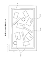
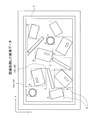
図3は本実施形態のピッキングシステム1においてカメラ2がコンテナ6内を撮像した画像データの一例を表し、図4は当該画像データに対して画像認識プロセッサ11が画像認識処理した結果の一例を表している。
図3は本実施形態のピッキングシステム1においてカメラ2がコンテナ6内を撮像した画像データの一例を表し、図4は当該画像データに対して画像認識プロセッサ11が画像認識処理した結果の一例を表している。
図示する例では、円筒形状の部品Aと、長円貫通孔が開いた板形状の部品Bと、上記部品Aよりも細くて長い棒形状の部品Cの3種類の工業部品A,B,Cがそれぞれ乱雑な姿勢でコンテナ内に配置されている。そのうち部品Aについては、一端部を下にして直立している姿勢のものと、側面を下にして横たわっている姿勢のものが混在している。また部品Bについては、全体が裏返って長円貫通孔の配置関係が異なるものが混在している。
このような画像データに対して、画像認識プロセッサ11は、各工業部品A,B,Cの個体それぞれの姿勢にかかわらず同じ種類の工業部品A,B,Cどうしで共通する外観形状のパターンを認識し、そのパターンに対応する種類を識別情報(図4中の「A」,「B」,「C」)として個別に出力する。つまり、本実施形態において画像認識プロセッサ11が行う識別情報の出力は、予め用意された複数の種類(この例のA,B,Cの3種)のうちから選択的に分類して出力するいわゆるクラスタリングにより行う。
また図示する例では、画像認識プロセッサ11は、画像データに設定された座標X-Yにおける各工業部品A,B,Cの配置領域をX軸、Y軸にそれぞれ平行な4辺を備えた四角形状の包囲枠線Sで包囲し、その包囲枠線Sにおける2つの対向点の各座標位置(図4中の(xia、yia)、(xib、yib))を個別に出力する。
<ニューラルネットワークの構成について>
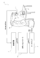
画像認識プロセッサ11は、上述したように、ニューラルネットワークを用いた機械学習によって各工業部品10の種類の認識と配置領域の検出を行う。本実施形態の例におけるこのニューラルネットワークは、例えば図5に示すモデル概略図のように、カメラ2から入力された2次元ピクセル列の画像データに基づいて、その画像中に存在する1つの工業部品10の種類(A,B,C)の識別情報をクラスタリングして出力する。なお図示する例では、識別情報を出力する具体的態様として、認識すべきパターンの種類(A,B,C)と同数の出力ノードを用意してそれらのうちから認識したパターンの種類に対応する1つの出力ノードのみから2値出力(例えば正論理で出力)している。また、このニューラルネットワークでは、認識した工業部品10の配置領域を示す包囲枠線Sの2対向点の各座標位置(xia、yia、xib、yib)も出力するよう設計されている。なお配置領域の出力は、いわゆる回帰問題により整数値の座標位置を出力するようニューラルネットワークを設計する。
画像認識プロセッサ11は、上述したように、ニューラルネットワークを用いた機械学習によって各工業部品10の種類の認識と配置領域の検出を行う。本実施形態の例におけるこのニューラルネットワークは、例えば図5に示すモデル概略図のように、カメラ2から入力された2次元ピクセル列の画像データに基づいて、その画像中に存在する1つの工業部品10の種類(A,B,C)の識別情報をクラスタリングして出力する。なお図示する例では、識別情報を出力する具体的態様として、認識すべきパターンの種類(A,B,C)と同数の出力ノードを用意してそれらのうちから認識したパターンの種類に対応する1つの出力ノードのみから2値出力(例えば正論理で出力)している。また、このニューラルネットワークでは、認識した工業部品10の配置領域を示す包囲枠線Sの2対向点の各座標位置(xia、yia、xib、yib)も出力するよう設計されている。なお配置領域の出力は、いわゆる回帰問題により整数値の座標位置を出力するようニューラルネットワークを設計する。
以上の基本仕様にあるニューラルネットワークにおいては、例えば入力層の直近をいわゆる畳み込み層とプーリング層の組み合わせである畳み込みニューラルネットワーク(特に図示せず)で構成することで柔軟なパターンの認識が可能となる。また例えば、出力層の直近をいわゆるパターン認識や最適値演算に適した全結合層(特に図示せず)で構成する。
また本実施形態の例のように画像データの画像中に複数の工業部品10が存在する場合には、いずれかの層、例えば図示するように上記の畳み込みニューラルネットワークと上記の全結合層の間の層において、認識処理の対象個体を指定するインデックスiを入力してもよい。このインデックスiについては、例えば画像の左上から所定方向に走査してi番目に位置する部品個体についての識別番号とし、識別情報と配置領域はこの入力されたインデックスiに対応する認識対象の工業部品10について出力される。
この画像認識プロセッサ11が備えるニューラルネットワークは、事前に認識対象である工業部品10(この例の部品A,B,C)の各種類について、それぞれ様々な姿勢の外観形状のパターンと出力すべき種類の識別情報との対応関係がすでに学習されている。この学習については、当該画像認識プロセッサ11の設計開発段階で別途の学習用コンピュータ(別の情報機器;特に図示せず)により事前に行われる。具体的には、当該学習用コンピュータが、同等の層構造にあるニューラルネットモデルに対して相当数の教師データ(入力するパターンデータと、出力すべき識別情報データ及び配置領域データを組み合わせたデータセット)を繰り返し与えた際に、その都度に入力層と出力層の間の関係性が成立するよう各ノードどうしをつなぐ各エッジの重み係数を調整するいわゆるバックプロパゲーション処理により学習を行う。なお、このようなバックプロパゲーションの他にも、いわゆるオートエンコーダ、ドロップアウト、ノイズ付加、及びスパース正則化などの多様な学習手法を併用して処理精度を向上させてもよい。そしてこれらの学習により得られた各重み係数の組み合わせ配列を画像認識プロセッサ11に記憶させることで、工業部品10の外観形状パターンと種類との相関を表す特徴量を学習したニューラルネットワークを備えることができる。
画像認識プロセッサ11における上記のようなニューラルネットワークの具体的な実装形態としては、いわゆるノイマン型デバイスによるソフトウェア処理で実装されてもよい。例えば、各ノードの出力とそれに接続する各エッジの重み係数の積算演算や、それらの積算結果どうしを加算する加算演算や、その加算結果が入力された各ノードの活性化関数演算について、行列式の内積演算(テンソル演算)の処理に特化した構成のノイマン型デバイス(いわゆるGPUやTPUと同等の集積回路)によるソフトウェア処理で実現してもよい。この場合は、主にデジタルデータ(離散値データ)を用いた逐次型処理となる。
または、画像認識プロセッサ11における上記ニューラルネットワークの他の具体的な実装形態として、いわゆるニューロモーフィック型デバイスでハードウェア的に実装されてもよい。例えば、各エッジの重み係数を抵抗値や静電容量などの物理量で保存し、これらと電流や電圧などで出力されるノード出力との積算値を表す物理量の加算値を、ハードウェア回路で活性化関数を実装した他のノードに入力することでいわゆるパーセプトロン(ニューラルネットワークの最小構成要素モデル)を実現してもよい。この場合は、デジタルデータ(離散値データ)とアナログデータ(連続値データ)のいずれか一方もしくは両方を用いた並列分散処理となる。
また、画像認識プロセッサ11の集積回路は、FPGA(Field Programmable Gate Array)、ASIC(Application Specific Integrated Circuit)、又はDSP(Digital Signal Processor)のいずれかの形態で構成することで、これまで開発されてきた集積回路の実装技術を利用した当該画像認識プロセッサ11の具現化が容易となる。
また、上記図4に示した各工業部品10の配置領域を示す包囲枠線Sについては、画像データを加工して当該画像データ中に描画してもよい。この描画処理は、画像認識プロセッサ11内で行ってもよいし、包囲枠線Sの2対向点の各座標位置(xia、yia、xib、yib)を受け取った後続の処理部(図示省略)で別途行ってもよい。また画像認識プロセッサ11が出力した配置領域に対し、ロボットコントローラ3の他の処理部(図示省略)で別途3Dレーザースキャナ等(特に図示せず)を用いて当該配置領域に存在する工業部品10の姿勢を例えば3次元CADモデル(識別情報の種類に対応して予め用意したモデル)などで検出してもよい。
以上において、ニューラルネットワークのネットワーク接続構成及び各エッジの重み係数の組み合わせ配列の全体が、各請求項記載の画像データ処理のアルゴリズムに相当する。また、このニューラルネットワークを上記ノイマン型デバイスで実装した場合において、ニューラルネットワークのネットワーク接続構成及び各エッジの重み係数の組み合わせ配列に対応する行列式を記憶するメモリ領域が各請求項記載の記憶部に相当し、その行列式演算を行う演算部分が各請求項記載の認識処理部に相当する。また、ニューラルネットワークを上記ニューロモーフィック型デバイスで実装した場合において、当該ニューラルネットワークを構成するハードウェア回路の全体が、各請求項記載の記憶部及び認識処理部に相当する。
<本実施形態による効果>
以上説明したように、本実施形態の画像認識プロセッサ11は、事前の学習に基づき確定した画像データ処理のアルゴリズムを記憶し、所定のパターンを含む画像の画像データを取得し、アルゴリズムに基づいて画像データの認識処理を行い、認識したパターンを識別する識別情報を出力する機能を集積回路に実装している。例えば、対象物が食品であれば惣菜専用の画像認識プロセッサや魚の切り身専用の画像認識プロセッサ、工業製品であればネジ専用の画像認識プロセッサやコンロッド専用の画像認識プロセッサ、化粧品であれば口紅専用の画像認識プロセッサや香水瓶専用の画像認識プロセッサ、薬品であれば風邪薬専用の画像認識プロセッサや胃腸薬専用の画像認識プロセッサ、文房具であればハサミ専用の画像認識プロセッサなどを作成することもできる。このように、特に工場などの作業現場で最小限必要とされるパターン認識とその識別情報の出力と言う機能だけに特化して集積回路に実装しているため、画像認識処理に必要な装置構成全体における大幅な小型化及び軽量化、消費電力の低減、及び処理の高速化が可能となる。この結果、画像認識処理の実用性を向上できる。
以上説明したように、本実施形態の画像認識プロセッサ11は、事前の学習に基づき確定した画像データ処理のアルゴリズムを記憶し、所定のパターンを含む画像の画像データを取得し、アルゴリズムに基づいて画像データの認識処理を行い、認識したパターンを識別する識別情報を出力する機能を集積回路に実装している。例えば、対象物が食品であれば惣菜専用の画像認識プロセッサや魚の切り身専用の画像認識プロセッサ、工業製品であればネジ専用の画像認識プロセッサやコンロッド専用の画像認識プロセッサ、化粧品であれば口紅専用の画像認識プロセッサや香水瓶専用の画像認識プロセッサ、薬品であれば風邪薬専用の画像認識プロセッサや胃腸薬専用の画像認識プロセッサ、文房具であればハサミ専用の画像認識プロセッサなどを作成することもできる。このように、特に工場などの作業現場で最小限必要とされるパターン認識とその識別情報の出力と言う機能だけに特化して集積回路に実装しているため、画像認識処理に必要な装置構成全体における大幅な小型化及び軽量化、消費電力の低減、及び処理の高速化が可能となる。この結果、画像認識処理の実用性を向上できる。
また、本実施形態では特に、認識したパターンの識別情報の出力は、予め用意された複数のパターンの種類のうちから選択的に分類してクラスタリング出力する。これにより、認識すべきパターンの種類を画像認識処理の用途(工業用、食品用など)に応じた複数の種類に限定して集積回路の回路規模を簡易化できる。また、出力する種類を明確化してその種類ごとに対応して行うべき後続制御(ロボットコントローラ3の作業計画部12における選別ピッキング制御)の選択が容易となる。なお上記実施形態では、認識すべきパターンの種類(A,B,C)と同数の出力ノードを用意し、それらのうちの認識したパターンの種類に対応する1つの出力ノードのみから2値出力(例えば正論理で出力)する態様としていたが、これに限られない。例えば、複数の出力ノードの2値出力を組み合わせた2進数表現で出力する態様等としてもよい。
また、本実施形態では特に、画像認識プロセッサ11は、画像データの画像中において認識したパターンの配置領域を検出して出力する。これにより、画像データを撮像したカメラ2などの撮像視野において、認識したパターンに対応する工業部品10の配置位置を概略的に把握することができ、認識されたパターンの識別情報に基づいてピッキングなどのハンドリングを行う場合にその配置位置を利用できる。
また、本実施形態では特に、配置領域の出力は、画像データを加工して画像中に出力(包囲枠線の描画)する。これにより、画像データの画像を特に図示しないディスプレイなどに表示した場合に、認識したパターンに対応する工業部品10の配置位置を視覚的に表示できる。なお、画像中における配置領域の描画出力は、上述した包囲枠線Sに限られない。例えば、画像中において認識したパターン全体のピクセルの塗りつぶし(識別情報に対応した色での塗りつぶし)等によって表現してもよい。
また、本実施形態では特に、アルゴリズムは、認識するパターンと識別情報との対応関係を学習したニューラルネットワーク(ディープラーニング、深層学習)により処理される。これにより、低消費電力で高速かつ高精度にパターンの認識を行うことが可能になる。なお、画像認識プロセッサ11に適用する機械学習としては、ニューラルネットワークを用いた深層学習以外にも、例えばサポートベクターマシン等のデータマイニングによる他の機械学習の手法を適用してもよい。
また、本実施形態では特に、ニューラルネットワークを、ノイマン型デバイス(逐次処理型デバイス)によるソフトウェア処理で実装することで、当該画像認識プロセッサ11の後続制御において利用する他のノイマン型デバイス(いわゆるCPU等)と電源などの設置環境で親和性の高い実装が可能となる。
また、本実施形態では特に、ニューラルネットワークを、ニューロモーフィック型デバイス(並列分散処理型デバイス)でハードウェア的に実装することで、さらなる低消費電力化、小型化及び軽量化、及び処理の高速化が可能となる。
また、本実施形態では特に、集積回路が、FPGA(Field Programmable Gate Array)、ASIC(Application Specific Integrated Circuit)、又はDSP(Digital Signal Processor)のいずれかの形態で構成されることで、これまで開発されてきた集積回路の実装技術を利用した当該画像認識プロセッサ11の具現化が容易となる。
なお、本実施形態の画像認識プロセッサ11は、認識すべき各種のパターンとその認識アルゴリズムをすでに学習済みであるニューラルネットワークを実装することを想定しているが、これに限られない。他にも、画像認識プロセッサ11の集積回路が、FPGAの形態で構成された場合には、アルゴリズムが書き換え可能に実装されてもよい。これにより、例えばアルゴリズムをニューラルネットワークで処理する場合において、当該ニューラルネットワーク全体における接続構成の設計や、各重み係数の学習及び設定をユーザ側で書き換えることができるため、画像データ認識処理の汎用性が向上する。また、さらに学習の進んだニューラルネットワークを実装した新しいアルゴリズムへの書き換えによるアップデートも容易となる。
また、本実施形態では特に、アルゴリズムは、予め別の情報機器(学習用コンピュータ)を用いて行われる学習によって確定される。これにより、アルゴリズムを確定するための学習に必要なハードウェアリソースをロボットコントローラ3と別体の情報機器で構成できるため、画像認識プロセッサ11及びそれを搭載するロボットコントローラ3などのアプリケーション機器自体の構成規模を大幅に簡略化できる。
また、本実施形態では特に、ロボットコントローラ3が、画像認識プロセッサ11で認識したパターンに対応する工業部品10に対して所定のピッキング制御を実行する。これにより、画像認識プロセッサ11を単に画像認識インターフェースとして組み込み、出力されたパターンの識別情報に対応した各種の後続制御の実行を実現できる。
また、本実施形態では特に、ロボットコントローラ3が、画像認識プロセッサ11を着脱交換可能に備えている。これにより、ロボットコントローラ3本体を共通化し、上記実施形態の例の工業部品10以外にも例えば食材などの認識対象物の分類別に特化した画像認識プロセッサ11を交換可能にすることで、ロボットコントローラ3の汎用性を向上できる。また、さらに学習の進んだニューラルネットワークを実装した新しい画像認識プロセッサ11への交換によるアップデートも容易となる。
<変形例>
なお、以上説明した実施形態は、その趣旨及び技術的思想を逸脱しない範囲内で種々の変形が可能である。
なお、以上説明した実施形態は、その趣旨及び技術的思想を逸脱しない範囲内で種々の変形が可能である。
<変形例1:アーム先端部にカメラと画像認識プロセッサを設置する場合>
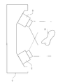
例えば、上記実施形態では、カメラ2を固定した定点撮像により画像データを取得していたが、これに限られない。例えば、図6に示すように、6軸ロボット5Aのアーム先端部5aにカメラ2を固定し、対象となる構造物21を構成する細部部品の形状を多様な視野方向で撮像して当該構造物21の組立検査を行えるようにしてもよい。
例えば、上記実施形態では、カメラ2を固定した定点撮像により画像データを取得していたが、これに限られない。例えば、図6に示すように、6軸ロボット5Aのアーム先端部5aにカメラ2を固定し、対象となる構造物21を構成する細部部品の形状を多様な視野方向で撮像して当該構造物21の組立検査を行えるようにしてもよい。
この場合、画像認識プロセッサ11は画像データから検査対象の細部部品のパターンを認識して識別情報と配置領域を出力し、これに基づいて検査装置7が検査結果を判定する。またこの検査装置7が細部部品の座標情報を出力し、これに基づいてロボットコントローラ3Aが構造物21の姿勢や配置を把握できる。これにより構造物21が不特定の姿勢と位置で配置された場合でも、ロボットコントローラ3Aは6軸ロボット5Aに設定された作業座標中において構造物21の姿勢と位置を把握できる。
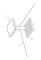
このような検査システム1A(産業機器)において、カメラ2の画像データを送信するのに必要な太いケーブルを6軸ロボット5Aのロボットアームに沿って長く引き回した場合には、ケーブルの重量がアーム動作制御に悪影響を与えやすいとともにケーブルが外部に干渉してロボットアームの動作制御を阻害しやすい。しかし、図6に示すように、アーム先端部5aでカメラ2の近傍に画像認識プロセッサ11も設置し、その識別情報及び配置領域の情報を送信する信号線をロボットアームの内部に配線した場合には、ロボットアーム全体が軽量となるとともに外部との干渉を回避できる点で有利である。この場合には、画像認識プロセッサ11が集積回路で実装した軽量な構成であることからも、ロボットアームの動作制御に大きく影響を与えることがないという利点がある。
<変形例2:複数のカメラで撮像した複数の画像データでパターン認識する場合>
図7に示す例では、それぞれの撮像領域が重複する2台のカメラ41,42で構成されたいわゆる3次元カメラ43を用いて1つの食品50(図示する例では鳥唐揚げ)をそれぞれ異なる撮像方向から撮像している。これにより、図8の左側に示すように、1つの食品50に対して相互に視差を有する2つの画像データ(それぞれ2次元ピクセル列)を取得することができる。
図7に示す例では、それぞれの撮像領域が重複する2台のカメラ41,42で構成されたいわゆる3次元カメラ43を用いて1つの食品50(図示する例では鳥唐揚げ)をそれぞれ異なる撮像方向から撮像している。これにより、図8の左側に示すように、1つの食品50に対して相互に視差を有する2つの画像データ(それぞれ2次元ピクセル列)を取得することができる。
図8に示す例では、画像認識プロセッサ11のニューラルネットワークが上記2つの画像データをそのまま個別に入力され、それら2つの画像データに基づいて食品50の形状パターンを認識するよう設計されている。このように3次元の画像データを用いることで、特に形状や大きさが不定である食品50に対して立体形状の空間認識精度が向上する。なお、カメラは撮像領域が重複すれば3つ以上用いてもよいし、画像認識プロセッサ11のニューラルネットワークにおいてそれぞれの画像データを個別の畳み込みニューラルネットワークで処理してから同一の全結合層でパターン認識してもよい。
<その他の変形例>
また特に図示しないが、対象物の画像データを取得する光学的センシング手段としてレーザースキャナ等をカメラ2(および3次元センサ8)の代わりに用いてもよい。この場合には、例えばレーザースキャナから投光された走査線で対象物の表面上における各点との距離を計測し、これらの距離データの集合で画像データを取得する。
また特に図示しないが、対象物の画像データを取得する光学的センシング手段としてレーザースキャナ等をカメラ2(および3次元センサ8)の代わりに用いてもよい。この場合には、例えばレーザースキャナから投光された走査線で対象物の表面上における各点との距離を計測し、これらの距離データの集合で画像データを取得する。
なお、以上の説明において、「垂直」「平行」「平面」等の記載がある場合には、当該記載は厳密な意味ではない。すなわち、それら「垂直」「平行」「平面」とは、設計上、製造上の公差、誤差が許容され、「実質的に垂直」「実質的に平行」「実質的に平面」という意味である。
また、以上の説明において、外観上の寸法や大きさ、形状、位置等が「同一」「同じ」「等しい」「異なる」等の記載がある場合は、当該記載は厳密な意味ではない。すなわち、それら「同一」「等しい」「異なる」とは、設計上、製造上の公差、誤差が許容され、「実質的に同一」「実質的に同じ」「実質的に等しい」「実質的に異なる」という意味である。
また、以上既に述べた以外にも、上記実施形態や各変形例による手法を適宜組み合わせて利用しても良い。その他、一々例示はしないが、上記実施形態や各変形例は、その趣旨を逸脱しない範囲内において、種々の変更が加えられて実施されるものである。
1 ピッキングシステム(産業機器)
1A 検査システム(産業機器)
2 カメラ
3 ロボットコントローラ
4 サーボアンプ
5 ピッキングロボット
6 コンテナ
8 3次元センサ
10 工業部品(対象物、制御対象物)
11 画像認識プロセッサ(産業機器用の画像認識プロセッサ)
12 作業計画部
13 逆キネマティクス演算部
16 距離認識部
43 3次元カメラ
50 食品
S 包囲枠線
1A 検査システム(産業機器)
2 カメラ
3 ロボットコントローラ
4 サーボアンプ
5 ピッキングロボット
6 コンテナ
8 3次元センサ
10 工業部品(対象物、制御対象物)
11 画像認識プロセッサ(産業機器用の画像認識プロセッサ)
12 作業計画部
13 逆キネマティクス演算部
16 距離認識部
43 3次元カメラ
50 食品
S 包囲枠線
Claims (13)
- 事前の学習に基づき確定した画像データ処理のアルゴリズムを記憶し、
所定のパターンを含む画像の画像データを取得し、
前記アルゴリズムに基づいて前記画像データの認識処理を行い、認識したパターンを識別する識別情報を出力する機能を集積回路に実装した
ことを特徴とする産業機器用の画像認識プロセッサ。 - 前記識別情報の出力は、予め用意された複数のパターンの種類のうちから選択的に分類して出力することを特徴とする請求項1記載の産業機器用の画像認識プロセッサ。
- 前記画像中において認識したパターンの配置領域を検出して出力することを特徴とする請求項1又は2記載の産業機器用の画像認識プロセッサ。
- 前記配置領域の出力は、前記画像データを加工して前記画像中に出力することを特徴とする請求項3記載の産業機器用の画像認識プロセッサ。
- 前記アルゴリズムは、認識する前記パターンと前記識別情報との対応関係を学習したニューラルネットワークにより処理されることを特徴とする請求項1乃至4のいずれか1項に記載の産業機器用の画像認識プロセッサ。
- 前記ニューラルネットワークは、ノイマン型デバイスによるソフトウェア処理で実装されることを特徴とする請求項5記載の産業機器用の画像認識プロセッサ。
- 前記ニューラルネットワークは、ニューロモーフィック型デバイスでハードウェア的に実装されることを特徴とする請求項5記載の産業機器用の画像認識プロセッサ。
- 前記集積回路は、FPGA(Field Programmable Gate Array)、ASIC(Application Specific Integrated Circuit)、又はDSP(Digital Signal Processor)のいずれかの形態で構成されることを特徴とする請求項5乃至7のいずれか1項に記載の産業機器用の画像認識プロセッサ。
- 前記集積回路は、前記FPGAの形態で構成され、
前記アルゴリズムは、書き換え可能に実装されることを特徴とする請求項8記載の産業機器用の画像認識プロセッサ。 - 前記アルゴリズムは、予め別の情報機器を用いて行われる学習によって確定されることを特徴とする請求項1乃至9のいずれか1項に記載の産業機器用の画像認識プロセッサ。
- 所定の属性の対象物の外観パターンを含む画像データを認識処理して学習することによって作成された画像データ認識処理のアルゴリズムを記憶する記憶部と、
前記アルゴリズムを用いて前記画像データの画像に含まれる前記外観パターンの認識処理を行う認識処理部と、
を備えたことを特徴とする産業機器用の画像認識プロセッサ。 - 請求項1乃至11のいずれか1項に記載の産業機器用の画像認識プロセッサで認識したパターンに対応する制御対象物に対して所定の後続制御を実行することを特徴とするコントローラ。
- 前記産業機器用の画像認識プロセッサを着脱交換可能に備えていることを特徴とする請求項12記載のコントローラ。
Priority Applications (4)
| Application Number | Priority Date | Filing Date | Title |
|---|---|---|---|
| EP17883649.0A EP3557521B1 (en) | 2016-12-19 | 2017-10-12 | Industrial device image recognition processor and controller |
| CN201780078312.6A CN110088797B (zh) | 2016-12-19 | 2017-10-12 | 工业设备图像识别处理器及控制器 |
| JP2018557561A JP7022076B2 (ja) | 2016-12-19 | 2017-10-12 | 産業機器用の画像認識プロセッサ及びコントローラ |
| US16/441,031 US11004191B2 (en) | 2016-12-19 | 2019-06-14 | Industrial device image recognition processor and controller |
Applications Claiming Priority (2)
| Application Number | Priority Date | Filing Date | Title |
|---|---|---|---|
| JP2016-245763 | 2016-12-19 | ||
| JP2016245763 | 2016-12-19 |
Related Child Applications (1)
| Application Number | Title | Priority Date | Filing Date |
|---|---|---|---|
| US16/441,031 Continuation US11004191B2 (en) | 2016-12-19 | 2019-06-14 | Industrial device image recognition processor and controller |
Publications (1)
| Publication Number | Publication Date |
|---|---|
| WO2018116589A1 true WO2018116589A1 (ja) | 2018-06-28 |
Family
ID=62626065
Family Applications (1)
| Application Number | Title | Priority Date | Filing Date |
|---|---|---|---|
| PCT/JP2017/036974 Ceased WO2018116589A1 (ja) | 2016-12-19 | 2017-10-12 | 産業機器用の画像認識プロセッサ及びコントローラ |
Country Status (5)
| Country | Link |
|---|---|
| US (1) | US11004191B2 (ja) |
| EP (1) | EP3557521B1 (ja) |
| JP (1) | JP7022076B2 (ja) |
| CN (1) | CN110088797B (ja) |
| WO (1) | WO2018116589A1 (ja) |
Cited By (5)
| Publication number | Priority date | Publication date | Assignee | Title |
|---|---|---|---|---|
| JP2020015141A (ja) * | 2018-07-26 | 2020-01-30 | Ntn株式会社 | 把持装置 |
| WO2021010298A1 (ja) * | 2019-07-12 | 2021-01-21 | 株式会社Roms | 物品管理システム、物流システム、サーバ機器、及び物品管理方法 |
| CN113379905A (zh) * | 2021-07-16 | 2021-09-10 | 秦皇岛信能能源设备有限公司 | 一种轮毂产线用3d视觉智能识别及控制系统 |
| US20210323145A1 (en) * | 2018-11-09 | 2021-10-21 | Omron Corporation | Robot control device, robot control method, and non-transitory computer readable storage medium |
| JP2022502796A (ja) * | 2018-10-19 | 2022-01-11 | ナノトロニクス イメージング インコーポレイテッドNanotronics Imaging, Inc. | 基板上の流動的対象を自動的にマッピングするための方法およびシステム |
Families Citing this family (12)
| Publication number | Priority date | Publication date | Assignee | Title |
|---|---|---|---|---|
| JP6333871B2 (ja) * | 2016-02-25 | 2018-05-30 | ファナック株式会社 | 入力画像から検出した対象物を表示する画像処理装置 |
| JP6453922B2 (ja) * | 2017-02-06 | 2019-01-16 | ファナック株式会社 | ワークの取り出し動作を改善するワーク取り出し装置およびワーク取り出し方法 |
| JP6680750B2 (ja) * | 2017-11-22 | 2020-04-15 | ファナック株式会社 | 制御装置及び機械学習装置 |
| CN113538652B (zh) * | 2018-09-19 | 2022-07-19 | 阿泰克欧洲公司 | 具有数据收集反馈的三维扫描器 |
| JP6656627B1 (ja) * | 2019-02-13 | 2020-03-04 | 日本金銭機械株式会社 | 紙幣取扱いシステム |
| JP7275759B2 (ja) * | 2019-03-28 | 2023-05-18 | セイコーエプソン株式会社 | 物体検出方法、物体検出装置およびロボットシステム |
| EP4023398A4 (en) * | 2019-08-26 | 2023-09-13 | Kawasaki Jukogyo Kabushiki Kaisha | INFORMATION PROCESSING DEVICE, CONFIGURATION DEVICE, IMAGE RECOGNITION SYSTEM, ROBOT SYSTEM, CONFIGURATION METHOD, LEARNING DEVICE, AND LEARNED MODEL GENERATION METHOD |
| JP7458741B2 (ja) * | 2019-10-21 | 2024-04-01 | キヤノン株式会社 | ロボット制御装置及びその制御方法及びプログラム |
| CN113064373B (zh) * | 2021-04-07 | 2022-04-15 | 四川中鼎智能技术有限公司 | 基于视频图像识别的工业水电设备逻辑信号控制方法、系统、终端及存储介质 |
| CN113156607B (zh) * | 2021-04-14 | 2023-07-14 | 广景视睿科技(深圳)有限公司 | 组装棱镜的方法、组装棱镜的装置以及组装棱镜的设备 |
| CN113524172B (zh) * | 2021-05-27 | 2023-04-18 | 中国科学院深圳先进技术研究院 | 机器人及其物品抓取方法、计算机可读存储介质 |
| CN117593554B (zh) * | 2023-12-28 | 2024-12-06 | 上海凯士比泵有限公司 | 用于预测转动设备的轴心轨迹的方法、设备和介质 |
Citations (5)
| Publication number | Priority date | Publication date | Assignee | Title |
|---|---|---|---|---|
| JP2009211178A (ja) * | 2008-02-29 | 2009-09-17 | Canon Inc | 画像処理装置、画像処理方法、プログラム及び記憶媒体 |
| JP2011235386A (ja) | 2010-05-10 | 2011-11-24 | National Institute Of Advanced Industrial Science & Technology | ロボットアームのためのハンドカメラ装置 |
| JP2013117795A (ja) * | 2011-12-01 | 2013-06-13 | Canon Inc | 画像処理装置、画像処理方法 |
| JP2015203680A (ja) * | 2014-04-16 | 2015-11-16 | キヤノン株式会社 | 情報処理装置、方法、プログラム |
| JP2016203293A (ja) * | 2015-04-21 | 2016-12-08 | 株式会社豊田自動織機 | ピッキング装置およびピッキング方法 |
Family Cites Families (12)
| Publication number | Priority date | Publication date | Assignee | Title |
|---|---|---|---|---|
| US5475768A (en) * | 1993-04-29 | 1995-12-12 | Canon Inc. | High accuracy optical character recognition using neural networks with centroid dithering |
| JP2003504765A (ja) * | 1999-07-07 | 2003-02-04 | レニショウ パブリック リミテッド カンパニー | ニューラルネットワーク |
| US7016885B1 (en) * | 2001-08-28 | 2006-03-21 | University Of Central Florida Research Foundation, Inc. | Self-designing intelligent signal processing system capable of evolutional learning for classification/recognition of one and multidimensional signals |
| JP2005267407A (ja) * | 2004-03-19 | 2005-09-29 | Canon Inc | パターン識別方法及びパターン識別装置 |
| JP4988408B2 (ja) | 2007-04-09 | 2012-08-01 | 株式会社デンソー | 画像認識装置 |
| US7857114B2 (en) * | 2008-07-07 | 2010-12-28 | Glory, Ltd. | Banknote discrimination apparatus and banknote discrimination method |
| JP2014093023A (ja) * | 2012-11-06 | 2014-05-19 | Canon Inc | 物体検出装置、物体検出方法及びプログラム |
| CN105938558B (zh) * | 2015-03-06 | 2021-02-09 | 松下知识产权经营株式会社 | 学习方法 |
| US9639781B2 (en) * | 2015-04-10 | 2017-05-02 | Cognex Corporation | Systems and methods for classification and alignment of highly similar or self-similar patterns |
| US10515304B2 (en) * | 2015-04-28 | 2019-12-24 | Qualcomm Incorporated | Filter specificity as training criterion for neural networks |
| US9767386B2 (en) * | 2015-06-23 | 2017-09-19 | Adobe Systems Incorporated | Training a classifier algorithm used for automatically generating tags to be applied to images |
| US9792531B2 (en) * | 2015-09-16 | 2017-10-17 | Siemens Healthcare Gmbh | Intelligent multi-scale medical image landmark detection |
-
2017
- 2017-10-12 EP EP17883649.0A patent/EP3557521B1/en active Active
- 2017-10-12 WO PCT/JP2017/036974 patent/WO2018116589A1/ja not_active Ceased
- 2017-10-12 JP JP2018557561A patent/JP7022076B2/ja active Active
- 2017-10-12 CN CN201780078312.6A patent/CN110088797B/zh active Active
-
2019
- 2019-06-14 US US16/441,031 patent/US11004191B2/en active Active
Patent Citations (5)
| Publication number | Priority date | Publication date | Assignee | Title |
|---|---|---|---|---|
| JP2009211178A (ja) * | 2008-02-29 | 2009-09-17 | Canon Inc | 画像処理装置、画像処理方法、プログラム及び記憶媒体 |
| JP2011235386A (ja) | 2010-05-10 | 2011-11-24 | National Institute Of Advanced Industrial Science & Technology | ロボットアームのためのハンドカメラ装置 |
| JP2013117795A (ja) * | 2011-12-01 | 2013-06-13 | Canon Inc | 画像処理装置、画像処理方法 |
| JP2015203680A (ja) * | 2014-04-16 | 2015-11-16 | キヤノン株式会社 | 情報処理装置、方法、プログラム |
| JP2016203293A (ja) * | 2015-04-21 | 2016-12-08 | 株式会社豊田自動織機 | ピッキング装置およびピッキング方法 |
Non-Patent Citations (1)
| Title |
|---|
| See also references of EP3557521A4 |
Cited By (15)
| Publication number | Priority date | Publication date | Assignee | Title |
|---|---|---|---|---|
| JP7191569B2 (ja) | 2018-07-26 | 2022-12-19 | Ntn株式会社 | 把持装置 |
| WO2020022302A1 (ja) * | 2018-07-26 | 2020-01-30 | Ntn株式会社 | 把持装置 |
| JP2020015141A (ja) * | 2018-07-26 | 2020-01-30 | Ntn株式会社 | 把持装置 |
| US12174361B2 (en) | 2018-10-19 | 2024-12-24 | Nanotronics Imaging, Inc. | Method and system for mapping objects on unknown specimens |
| US11815673B2 (en) | 2018-10-19 | 2023-11-14 | Nanotronics Imaging, Inc. | Method and system for mapping objects on unknown specimens |
| JP2022502796A (ja) * | 2018-10-19 | 2022-01-11 | ナノトロニクス イメージング インコーポレイテッドNanotronics Imaging, Inc. | 基板上の流動的対象を自動的にマッピングするための方法およびシステム |
| JP7226852B2 (ja) | 2018-10-19 | 2023-02-21 | ナノトロニクス イメージング インコーポレイテッド | 基板上の流動的対象を自動的にマッピングするための方法およびシステム |
| US20210323145A1 (en) * | 2018-11-09 | 2021-10-21 | Omron Corporation | Robot control device, robot control method, and non-transitory computer readable storage medium |
| JPWO2021010298A1 (ja) * | 2019-07-12 | 2021-01-21 | ||
| JP7212910B2 (ja) | 2019-07-12 | 2023-01-26 | 株式会社Roms | 物品管理システム、物流システム、サーバ機器、及び物品管理方法 |
| CN114127762A (zh) * | 2019-07-12 | 2022-03-01 | 株式会社Roms | 物品管理系统、物流系统、服务器设备以及物品管理方法 |
| WO2021010298A1 (ja) * | 2019-07-12 | 2021-01-21 | 株式会社Roms | 物品管理システム、物流システム、サーバ機器、及び物品管理方法 |
| US12351392B2 (en) | 2019-07-12 | 2025-07-08 | Roms Inc | Article management system, logistics system, server device, and article management method |
| CN114127762B (zh) * | 2019-07-12 | 2026-03-20 | 株式会社Roms | 物品管理系统、物流系统、服务器设备以及物品管理方法 |
| CN113379905A (zh) * | 2021-07-16 | 2021-09-10 | 秦皇岛信能能源设备有限公司 | 一种轮毂产线用3d视觉智能识别及控制系统 |
Also Published As
| Publication number | Publication date |
|---|---|
| US20190295244A1 (en) | 2019-09-26 |
| JP7022076B2 (ja) | 2022-02-17 |
| JPWO2018116589A1 (ja) | 2019-06-24 |
| EP3557521A1 (en) | 2019-10-23 |
| CN110088797A (zh) | 2019-08-02 |
| US11004191B2 (en) | 2021-05-11 |
| EP3557521B1 (en) | 2024-09-25 |
| EP3557521A4 (en) | 2020-08-05 |
| CN110088797B (zh) | 2023-04-21 |
Similar Documents
| Publication | Publication Date | Title |
|---|---|---|
| JP7022076B2 (ja) | 産業機器用の画像認識プロセッサ及びコントローラ | |
| JP7693649B2 (ja) | 移動操作システムの視覚的教示と繰り返し | |
| JP5977544B2 (ja) | 情報処理装置、情報処理方法 | |
| JP5897624B2 (ja) | ワークの取出工程をシミュレーションするロボットシミュレーション装置 | |
| JP6931457B2 (ja) | モーション生成方法、モーション生成装置、システム及びコンピュータプログラム | |
| JP5835926B2 (ja) | 情報処理装置、情報処理装置の制御方法、およびプログラム | |
| JP5743499B2 (ja) | 画像生成装置、画像生成方法、およびプログラム | |
| US20180290307A1 (en) | Information processing apparatus, measuring apparatus, system, interference determination method, and article manufacturing method | |
| Rolley-Parnell et al. | Bi-manual articulated robot teleoperation using an external RGB-D range sensor | |
| Romero et al. | Eyesight hand: Design of a fully-actuated dexterous robot hand with integrated vision-based tactile sensors and compliant actuation | |
| CN114494426A (zh) | 用于控制机器人来在不同的方位拿起对象的装置和方法 | |
| JP7008136B2 (ja) | 機械学習装置及びこれを備えたロボットシステム | |
| KR20230122118A (ko) | 지도된 자율 파지 | |
| JP7051751B2 (ja) | 学習装置、学習方法、学習モデル、検出装置及び把持システム | |
| CN115194774A (zh) | 一种基于多目视觉的双机械臂抓握系统控制方法 | |
| JP2018176311A (ja) | 情報処理装置、情報処理方法、プログラム、システム、および物品製造方法 | |
| JP2021061014A (ja) | 学習装置、学習方法、学習モデル、検出装置及び把持システム | |
| Trung et al. | Development of an Intelligence Vision for a Robot System to Pick and Place Objects. | |
| CN116175542B (zh) | 确定夹具抓取顺序的方法、装置、电子设备和存储介质 | |
| CN117621032A (zh) | 一种物体拾取方法以及相关设备 | |
| Wang et al. | A visual servoing system for interactive human-robot object transfer | |
| Nguyen et al. | Designing of A Plastic Garbage Robot With Vision-Based Deep Learning Applications | |
| Chen et al. | Precision grasping based on probabilistic models of unknown objects | |
| Xu et al. | Collision-Free Trajectory Planning with Digital Twin Support for Robotic Bin Picking from Unstructured Bins | |
| Yesudasu | Enhancing Logistics Automation with AI: Application of Dual-arm Humanoid Torso for Al-powered Depalletizingand Package Handling. |
Legal Events
| Date | Code | Title | Description |
|---|---|---|---|
| 121 | Ep: the epo has been informed by wipo that ep was designated in this application |
Ref document number: 17883649 Country of ref document: EP Kind code of ref document: A1 |
|
| ENP | Entry into the national phase |
Ref document number: 2018557561 Country of ref document: JP Kind code of ref document: A |
|
| NENP | Non-entry into the national phase |
Ref country code: DE |
|
| WWE | Wipo information: entry into national phase |
Ref document number: 2017883649 Country of ref document: EP |