WO2018117042A1 - キャップの開閉構造および充電用コネクタ - Google Patents
キャップの開閉構造および充電用コネクタ Download PDFInfo
- Publication number
- WO2018117042A1 WO2018117042A1 PCT/JP2017/045373 JP2017045373W WO2018117042A1 WO 2018117042 A1 WO2018117042 A1 WO 2018117042A1 JP 2017045373 W JP2017045373 W JP 2017045373W WO 2018117042 A1 WO2018117042 A1 WO 2018117042A1
- Authority
- WO
- WIPO (PCT)
- Prior art keywords
- cap
- closing structure
- rotation
- opening
- support portion
- Prior art date
- Legal status (The legal status is an assumption and is not a legal conclusion. Google has not performed a legal analysis and makes no representation as to the accuracy of the status listed.)
- Ceased
Links
Images


Classifications
-
- B—PERFORMING OPERATIONS; TRANSPORTING
- B60—VEHICLES IN GENERAL
- B60K—ARRANGEMENT OR MOUNTING OF PROPULSION UNITS OR OF TRANSMISSIONS IN VEHICLES; ARRANGEMENT OR MOUNTING OF PLURAL DIVERSE PRIME-MOVERS IN VEHICLES; AUXILIARY DRIVES FOR VEHICLES; INSTRUMENTATION OR DASHBOARDS FOR VEHICLES; ARRANGEMENTS IN CONNECTION WITH COOLING, AIR INTAKE, GAS EXHAUST OR FUEL SUPPLY OF PROPULSION UNITS IN VEHICLES
- B60K1/00—Arrangement or mounting of electrical propulsion units
- B60K1/04—Arrangement or mounting of electrical propulsion units of the electric storage means for propulsion
-
- B—PERFORMING OPERATIONS; TRANSPORTING
- B60—VEHICLES IN GENERAL
- B60K—ARRANGEMENT OR MOUNTING OF PROPULSION UNITS OR OF TRANSMISSIONS IN VEHICLES; ARRANGEMENT OR MOUNTING OF PLURAL DIVERSE PRIME-MOVERS IN VEHICLES; AUXILIARY DRIVES FOR VEHICLES; INSTRUMENTATION OR DASHBOARDS FOR VEHICLES; ARRANGEMENTS IN CONNECTION WITH COOLING, AIR INTAKE, GAS EXHAUST OR FUEL SUPPLY OF PROPULSION UNITS IN VEHICLES
- B60K15/00—Arrangement in connection with fuel supply of combustion engines or other fuel consuming energy converters, e.g. fuel cells; Mounting or construction of fuel tanks
- B60K15/03—Fuel tanks
- B60K15/04—Tank inlets
- B60K15/05—Inlet covers
-
- B—PERFORMING OPERATIONS; TRANSPORTING
- B60—VEHICLES IN GENERAL
- B60L—PROPULSION OF ELECTRICALLY-PROPELLED VEHICLES; SUPPLYING ELECTRIC POWER FOR AUXILIARY EQUIPMENT OF ELECTRICALLY-PROPELLED VEHICLES; ELECTRODYNAMIC BRAKE SYSTEMS FOR VEHICLES IN GENERAL; MAGNETIC SUSPENSION OR LEVITATION FOR VEHICLES; MONITORING OPERATING VARIABLES OF ELECTRICALLY-PROPELLED VEHICLES; ELECTRIC SAFETY DEVICES FOR ELECTRICALLY-PROPELLED VEHICLES
- B60L50/00—Electric propulsion with power supplied within the vehicle
- B60L50/50—Electric propulsion with power supplied within the vehicle using propulsion power supplied by batteries or fuel cells
-
- B—PERFORMING OPERATIONS; TRANSPORTING
- B60—VEHICLES IN GENERAL
- B60L—PROPULSION OF ELECTRICALLY-PROPELLED VEHICLES; SUPPLYING ELECTRIC POWER FOR AUXILIARY EQUIPMENT OF ELECTRICALLY-PROPELLED VEHICLES; ELECTRODYNAMIC BRAKE SYSTEMS FOR VEHICLES IN GENERAL; MAGNETIC SUSPENSION OR LEVITATION FOR VEHICLES; MONITORING OPERATING VARIABLES OF ELECTRICALLY-PROPELLED VEHICLES; ELECTRIC SAFETY DEVICES FOR ELECTRICALLY-PROPELLED VEHICLES
- B60L53/00—Methods of charging batteries, specially adapted for electric vehicles; Charging stations or on-board charging equipment therefor; Exchange of energy storage elements in electric vehicles
- B60L53/10—Methods of charging batteries, specially adapted for electric vehicles; Charging stations or on-board charging equipment therefor; Exchange of energy storage elements in electric vehicles characterised by the energy transfer between the charging station and the vehicle
- B60L53/14—Conductive energy transfer
- B60L53/16—Connectors, e.g. plugs or sockets, specially adapted for charging electric vehicles
-
- B—PERFORMING OPERATIONS; TRANSPORTING
- B60—VEHICLES IN GENERAL
- B60R—VEHICLES, VEHICLE FITTINGS, OR VEHICLE PARTS, NOT OTHERWISE PROVIDED FOR
- B60R16/00—Electric or fluid circuits specially adapted for vehicles and not otherwise provided for; Arrangement of elements of electric or fluid circuits specially adapted for vehicles and not otherwise provided for
- B60R16/02—Electric or fluid circuits specially adapted for vehicles and not otherwise provided for; Arrangement of elements of electric or fluid circuits specially adapted for vehicles and not otherwise provided for electric constitutive elements
- B60R16/04—Arrangement of batteries
-
- E—FIXED CONSTRUCTIONS
- E05—LOCKS; KEYS; WINDOW OR DOOR FITTINGS; SAFES
- E05B—LOCKS; ACCESSORIES THEREFOR; HANDCUFFS
- E05B83/00—Vehicle locks specially adapted for particular types of wing or vehicle
- E05B83/28—Locks for glove compartments, console boxes, fuel inlet covers or the like
- E05B83/34—Locks for glove compartments, console boxes, fuel inlet covers or the like for fuel inlet covers essentially flush with the vehicle surface
-
- H—ELECTRICITY
- H01—ELECTRIC ELEMENTS
- H01R—ELECTRICALLY-CONDUCTIVE CONNECTIONS; STRUCTURAL ASSOCIATIONS OF A PLURALITY OF MUTUALLY-INSULATED ELECTRICAL CONNECTING ELEMENTS; COUPLING DEVICES; CURRENT COLLECTORS
- H01R13/00—Details of coupling devices of the kinds covered by groups H01R12/70 or H01R24/00 - H01R33/00
- H01R13/44—Means for preventing access to live contacts
- H01R13/447—Shutter or cover plate
- H01R13/453—Shutter or cover plate opened by engagement of counterpart
- H01R13/4532—Rotating shutter
-
- H—ELECTRICITY
- H01—ELECTRIC ELEMENTS
- H01R—ELECTRICALLY-CONDUCTIVE CONNECTIONS; STRUCTURAL ASSOCIATIONS OF A PLURALITY OF MUTUALLY-INSULATED ELECTRICAL CONNECTING ELEMENTS; COUPLING DEVICES; CURRENT COLLECTORS
- H01R13/00—Details of coupling devices of the kinds covered by groups H01R12/70 or H01R24/00 - H01R33/00
- H01R13/46—Bases; Cases
- H01R13/52—Dustproof, splashproof, drip-proof, waterproof, or flameproof cases
- H01R13/5213—Covers
-
- B—PERFORMING OPERATIONS; TRANSPORTING
- B60—VEHICLES IN GENERAL
- B60K—ARRANGEMENT OR MOUNTING OF PROPULSION UNITS OR OF TRANSMISSIONS IN VEHICLES; ARRANGEMENT OR MOUNTING OF PLURAL DIVERSE PRIME-MOVERS IN VEHICLES; AUXILIARY DRIVES FOR VEHICLES; INSTRUMENTATION OR DASHBOARDS FOR VEHICLES; ARRANGEMENTS IN CONNECTION WITH COOLING, AIR INTAKE, GAS EXHAUST OR FUEL SUPPLY OF PROPULSION UNITS IN VEHICLES
- B60K15/00—Arrangement in connection with fuel supply of combustion engines or other fuel consuming energy converters, e.g. fuel cells; Mounting or construction of fuel tanks
- B60K15/03—Fuel tanks
- B60K15/04—Tank inlets
- B60K15/05—Inlet covers
- B60K2015/0515—Arrangements for closing or opening of inlet cover
- B60K2015/053—Arrangements for closing or opening of inlet cover with hinged connection to the vehicle body
-
- H—ELECTRICITY
- H01—ELECTRIC ELEMENTS
- H01R—ELECTRICALLY-CONDUCTIVE CONNECTIONS; STRUCTURAL ASSOCIATIONS OF A PLURALITY OF MUTUALLY-INSULATED ELECTRICAL CONNECTING ELEMENTS; COUPLING DEVICES; CURRENT COLLECTORS
- H01R2201/00—Connectors or connections adapted for particular applications
- H01R2201/26—Connectors or connections adapted for particular applications for vehicles
-
- Y—GENERAL TAGGING OF NEW TECHNOLOGICAL DEVELOPMENTS; GENERAL TAGGING OF CROSS-SECTIONAL TECHNOLOGIES SPANNING OVER SEVERAL SECTIONS OF THE IPC; TECHNICAL SUBJECTS COVERED BY FORMER USPC CROSS-REFERENCE ART COLLECTIONS [XRACs] AND DIGESTS
- Y02—TECHNOLOGIES OR APPLICATIONS FOR MITIGATION OR ADAPTATION AGAINST CLIMATE CHANGE
- Y02T—CLIMATE CHANGE MITIGATION TECHNOLOGIES RELATED TO TRANSPORTATION
- Y02T10/00—Road transport of goods or passengers
- Y02T10/60—Other road transportation technologies with climate change mitigation effect
- Y02T10/70—Energy storage systems for electromobility, e.g. batteries
-
- Y—GENERAL TAGGING OF NEW TECHNOLOGICAL DEVELOPMENTS; GENERAL TAGGING OF CROSS-SECTIONAL TECHNOLOGIES SPANNING OVER SEVERAL SECTIONS OF THE IPC; TECHNICAL SUBJECTS COVERED BY FORMER USPC CROSS-REFERENCE ART COLLECTIONS [XRACs] AND DIGESTS
- Y02—TECHNOLOGIES OR APPLICATIONS FOR MITIGATION OR ADAPTATION AGAINST CLIMATE CHANGE
- Y02T—CLIMATE CHANGE MITIGATION TECHNOLOGIES RELATED TO TRANSPORTATION
- Y02T10/00—Road transport of goods or passengers
- Y02T10/60—Other road transportation technologies with climate change mitigation effect
- Y02T10/7072—Electromobility specific charging systems or methods for batteries, ultracapacitors, supercapacitors or double-layer capacitors
-
- Y—GENERAL TAGGING OF NEW TECHNOLOGICAL DEVELOPMENTS; GENERAL TAGGING OF CROSS-SECTIONAL TECHNOLOGIES SPANNING OVER SEVERAL SECTIONS OF THE IPC; TECHNICAL SUBJECTS COVERED BY FORMER USPC CROSS-REFERENCE ART COLLECTIONS [XRACs] AND DIGESTS
- Y02—TECHNOLOGIES OR APPLICATIONS FOR MITIGATION OR ADAPTATION AGAINST CLIMATE CHANGE
- Y02T—CLIMATE CHANGE MITIGATION TECHNOLOGIES RELATED TO TRANSPORTATION
- Y02T90/00—Enabling technologies or technologies with a potential or indirect contribution to GHG emissions mitigation
- Y02T90/10—Technologies relating to charging of electric vehicles
- Y02T90/12—Electric charging stations
-
- Y—GENERAL TAGGING OF NEW TECHNOLOGICAL DEVELOPMENTS; GENERAL TAGGING OF CROSS-SECTIONAL TECHNOLOGIES SPANNING OVER SEVERAL SECTIONS OF THE IPC; TECHNICAL SUBJECTS COVERED BY FORMER USPC CROSS-REFERENCE ART COLLECTIONS [XRACs] AND DIGESTS
- Y02—TECHNOLOGIES OR APPLICATIONS FOR MITIGATION OR ADAPTATION AGAINST CLIMATE CHANGE
- Y02T—CLIMATE CHANGE MITIGATION TECHNOLOGIES RELATED TO TRANSPORTATION
- Y02T90/00—Enabling technologies or technologies with a potential or indirect contribution to GHG emissions mitigation
- Y02T90/10—Technologies relating to charging of electric vehicles
- Y02T90/14—Plug-in electric vehicles
Definitions
- the present invention relates to a cap opening / closing structure and a charging connector.
- a vehicle-side charging connector having a cap that can be opened and closed so as to cover a connection portion to which the charging connector is connected is used. Yes.
- a biasing member such as a spring biases the cap in the opening direction.
- the cap is locked to the housing, but when the operator releases this locking, the cap is opened by the biasing force of the biasing member.
- An object of the present invention is to provide a cap opening and closing structure and a charging connector that can suppress the momentum when the cap is opened with a simple configuration and can suppress flapping when the cap is fully opened.
- a cap opening / closing structure comprises a connection object external to a vehicle, a housing provided with a connection part electrically connected through an opening, and a rotation support part at one end.
- a cap that is pivotally supported with respect to the housing, closes the opening in a closed position, and exposes the connecting portion to the outside of the vehicle through the opening in an open position; and
- a first urging member that urges to rotate about a rotation axis from the closed position toward the open position, and is formed on each of the housing and the cap, and maintains an opposing state when the cap is rotated.
- the convex portion has a concave portion with which the convex portion engages, and at least one of the convex portion and the concave portion has two inclined surfaces opposed to each other in the rotation direction. In the position, the convex portion and the concave portion are formed so as to extend in the engagement direction from the adjacent end portions facing each other toward the separated end portions facing away from each other.
- the two inclined surfaces are formed so that the proximate end portion is in a non-contact state at the open position and the convex portion is engaged with the concave portion.
- the first facing surface and the second facing surface are opposed to each other on a rotating shaft, and one of the engaging portions rotates with respect to the rotating support portion.
- the second urging member is supported between the one engagement portion and the rotation support portion or the housing, and the one engagement portion is disposed on the rotation shaft. It is preferable that the direction is biased toward one of the first facing surface and the second facing surface.
- the first facing surface and the second facing surface are opposed to each other in the radial direction of the rotation support portion, and one of the engagement portions is the rotation support portion.
- the second urging member is provided between one of the engaging portions and the rotation supporting portion or the housing, and the one engaging portion is It is preferable to urge the first facing surface or the second facing surface side radially outward.
- the second urging member includes the facing surface that faces one of the engaging portions when the first engaging portion and the second engaging portion are not engaged. It is preferable to make it contact.
- the first facing surface and the second facing surface are spaced apart in the radial direction of the rotational support portion from the open position to the closed position in the rotational direction. Is preferred.
- a charging connector according to the present invention is electrically connected between the cap opening / closing structure according to any one of claims 1 to 6 and a charging connector outside the vehicle. Connecting portion.
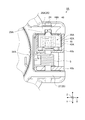
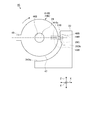
- FIG. 1 is a perspective view illustrating a schematic configuration of a charging connector to which the cap opening / closing structure according to the first embodiment is applied.
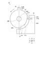
- FIG. 2 is a side view illustrating a schematic configuration of a charging connector to which the cap opening / closing structure according to the first embodiment is applied.
- FIG. 3 is an exploded perspective view showing a schematic configuration of the cap opening and closing structure according to the first embodiment.
- FIG. 4 is a side view illustrating a schematic configuration of an inlet damper in the cap opening and closing structure according to the first embodiment.
- FIG. 7 is a partial cross-sectional view illustrating a schematic configuration of a cap opening / closing structure according to the first embodiment.
- FIG. 8 is a partial cross-sectional view illustrating a schematic configuration of the cap opening and closing structure according to the first embodiment.
- FIG. 9 is a schematic diagram showing an engaging operation between a convex portion and a concave portion in the cap opening / closing structure.
- FIG. 10 is a schematic diagram illustrating a schematic configuration of a cap opening / closing structure according to the second embodiment.
- FIG. 11 is a schematic diagram illustrating a schematic configuration of a cap opening / closing structure according to the second embodiment.
- FIG. 12 is a side view illustrating a schematic configuration of the inlet damper in the cap opening and closing structure according to the second embodiment.
- FIG. 13 is a side view illustrating a schematic configuration of the first support portion of the housing according to the second embodiment.
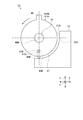
- FIG. 14 is a schematic diagram illustrating a schematic configuration of a cap opening / closing structure according to the third embodiment.
- FIG. 15 is a schematic diagram illustrating a schematic configuration of a cap opening / closing structure according to the third embodiment.
- FIG. 16 is a schematic diagram illustrating a schematic configuration of a cap opening / closing structure according to the fourth embodiment.
- FIG. 17 is a schematic diagram illustrating a schematic configuration of a cap opening / closing structure according to the fourth embodiment.
- FIG. 18 is a schematic diagram illustrating a schematic configuration of a cap opening / closing structure according to the first modification of the third embodiment.
- FIG. 19 is a schematic diagram illustrating a schematic configuration of a cap opening / closing structure according to the first modification of the third embodiment.
- FIG. 20 is a schematic diagram illustrating a schematic configuration of a cap opening / closing structure according to the second modification of the third embodiment.
- FIG. 21 is a schematic diagram illustrating a schematic configuration of a cap opening / closing structure according to the second modification of the third embodiment.
- FIG. 22 is a schematic diagram illustrating another example of the engaging operation between the convex portion and the concave portion in the cap opening and closing structure.
- FIG. 1 is a perspective view illustrating a schematic configuration of a charging connector to which the cap opening / closing structure according to the first embodiment is applied.
- FIG. 2 is a side view illustrating a schematic configuration of a charging connector to which the cap opening / closing structure according to the first embodiment is applied.
- FIG. 3 is an exploded perspective view showing a schematic configuration of the cap opening and closing structure according to the first embodiment.
- FIG. 4 is a side view illustrating a schematic configuration of an inlet damper in the cap opening and closing structure according to the first embodiment.
- FIG. 5 is a partial perspective view illustrating a schematic configuration of an inlet damper support portion in the cap opening / closing structure according to the first embodiment.
- 6 is a cross-sectional view taken along line AA in FIG.
- FIG. 7 is a partial cross-sectional view illustrating a schematic configuration of a cap opening / closing structure according to the first embodiment.
- FIG. 8 is a partial cross-sectional view illustrating a schematic configuration of the cap opening and closing structure according to the first embodiment.
- FIG. 9 is a schematic diagram showing an engaging operation between the convex portion and the concave portion of the cap opening / closing structure. 1 shows a state where the cap is in the open position, and FIG. 2 shows a state where the cap is in the closed position.
- FIG. 1 shows a state where the cap is in the open position
- FIG. 2 shows a state where the cap is in the closed position.
- FIG. 1 shows a state where the cap is in the open position
- FIG. 2 shows a state where the cap
- FIG. 5 shows a cap support portion of a housing that supports the cap.
- FIG. 6 shows a cross-section of the rotation support portion of the cap in the charging connector with the cap open.
- FIG. 7 shows a state where the cap is in the closed position, and
- FIG. 8 shows a state where the cap is in the open position.
- the X direction shown in the figure is the width direction of the charging connector in the embodiment, and is the direction orthogonal to the rotation axis direction of the cap.
- the Y direction is the rotational axis direction of the cap of the charging connector in the embodiment, and is the direction orthogonal to the X direction.
- the Z direction is a vertical direction of the charging connector in the embodiment, and is a direction orthogonal to the X direction and the Y direction.
- the Z direction is the vertical direction of the charging connector and is not limited to the vertical direction.
- a charging connector 100 to which the cap opening / closing structure 1A according to the first embodiment is applied will be described.
- a charging connector 100 shown in FIGS. 1 and 2 is provided in a vehicle such as an electric vehicle (EV) or a plug-in hybrid vehicle (PHEV), and is provided outside the vehicle for charging a battery mounted on the vehicle. It is electrically connected to the charging connector.
- Charging connector 100 is fixed to a vehicle body panel of the vehicle.
- the cap opening / closing structure 1 ⁇ / b> A includes a housing 2, a torsion spring 3, and a cap 4.
- the housing 2 has a connection part 22b that is electrically connected to an object to be connected outside the vehicle via the opening 22a.
- the connection target outside the vehicle is, for example, a charging connector.
- the housing 2 includes a vehicle body attachment portion 21, a housing body 22, a hood portion 23, a hinge pin 24, a cap support portion 25, and a cap lock portion 28.
- the vehicle body attachment portion 21 is made of a synthetic resin and made of a substantially rectangular plate-like member, and is provided with through holes 21a that are attachment holes to a vehicle body panel (not shown) at four corners.
- the vehicle body attachment portion 21 is fixed to the vehicle body panel by inserting bolts (not shown) through the four through holes 21a and tightening the vehicle body panel.
- the housing body 22 is made of a synthetic resin and made of a cylindrical member, and extends from the approximate center of the vehicle body mounting portion 21 in the vertical direction.
- the housing body 22 includes a connecting portion 22b including an opening 22a in an upward direction toward the outside of the vehicle.
- the connecting portion 22b is electrically connected to the charging connector outside the vehicle via the opening 22a.
- a terminal fitting (not shown) connected to an electric wire (not shown) extending from a battery (not shown) inside the vehicle is accommodated inside the connection portion 22b.
- the hood portion 23 is made of a synthetic resin and has a substantially cylindrical shape, and is provided on the upper side in the Z direction with respect to the vehicle body attachment portion 21 so as to cover the connection portion 22b from the outer periphery.
- the hood portion 23 is provided with a cap support portion 25 and a cap lock portion 28 on the outer peripheral surface thereof.
- the hinge pin 24 is a metal elongated bar-like member, and is inserted through the torsion spring 3 and the cap 4 via the cap support portion 25 in the Y direction, that is, the rotational axis direction of the cap 4.
- the hinge pin 24 rotates the cap 4 with respect to the housing 2 around the rotation axis.
- the cap support part 25 supports the cap 4 by the hinge pin 24 so as to be rotatable.
- the cap support part 25 is composed of a pair of first support parts 26 ⁇ / b> A and second support parts 27 provided at positions facing each other with a space therebetween.
- the cap support part 25 holds the cap 4 from the rotation axis direction by the first support part 26A and the second support part 27.
- the first support portion 26A has an insertion hole 26a through which the hinge pin 24 is inserted and a concave portion 29A on the side surface 30A facing the second support portion 27.
- the second support portion 27 has an insertion hole 27a through which the hinge pin 24 is inserted.
- the concave portion 29A is a first engagement portion or a second engagement portion, and is recessed in the direction of the rotation axis of the cap 4 and extends in a vertical direction (Z direction) perpendicular to the rotation axis direction to form a groove shape. It is formed.
- the recess 29A includes a bottom surface 290, a pair of end portions 290a, a pair of inner side surfaces 291 rising vertically from the end portions 290a at both ends of the bottom surface 290, and a pair of end portions 292A. Is done.
- the bottom surface 290 is formed between the end portions 290a facing in the rotation direction.
- the end 292A is located at a position where the inner surface 291 and the side surface 30A are in contact with each other at a right angle.
- the cap lock portion 28 is a locking mechanism that is provided on the outer peripheral surface of the hood portion 23 on the opposite side of the cap support portion 25 and locks the cap 4 in the closed position.
- the torsion spring 3 is a first biasing member, for example, a metal torsion coil spring.
- the torsion spring 3 urges the cap 4 to rotate about a rotation axis from the closed position toward the open position.
- the torsion spring 3 is disposed between the first support portion 26A and the second support portion 27 together with the rotation support portion 41b of the cap 4, and the hinge pin 24 is inserted on the inner peripheral side.
- One end of the torsion spring 3 is locked to the outer peripheral surface 31A of the hood portion 23 of the housing 2 shown in FIGS. 5 to 8, and the other end is locked to the outer surface 41d of the rotation support portion 41b of the cap 4. .
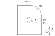
- the cap 4 closes the opening 22a in the closed position, and exposes the connecting portion 22b to the outside of the vehicle through the opening 22a in the open position.
- the cap 4 includes a synthetic resin cap body 41, a synthetic resin inlet damper 42A, and a metal inlet damper spring 43A.
- the cap body 41 includes a lid portion 41a, a rotation support portion 41b, a housing portion 41c, an outer side surface 41d facing the housing 2, and a rotation preventing portion 41e.
- the lid portion 41a is made of a substantially circular plate-like member, and closes so that the cap 4 covers the opening 22a in the closed position, while the cap 4 exposes the connecting portion 22b through the opening 22a in the open position.
- the rotation support portion 41 b is provided at one end of the lid portion 41 a and is supported rotatably with respect to the housing 2.
- the accommodating part 41c opens in the direction of the rotational axis of the rotational support part 41b, accommodates the inlet damper spring 43A and the inlet damper 42A in order from one opening, and inserts the hinge pin 24 from the other opening.
- the outer side surface 41d is curved in an arc shape along the rotation direction of the rotation support portion 41b, that is, is curved along an arc (arc surface) centering on the rotation axis of the cap 4.
- the rotation preventing portion 41e is a protrusion formed on the outer surface 41d of the rotation support portion 41b and extending in the rotation axis direction.
- the cap 4 abuts on the outer peripheral surface 31A of the hood portion 23 in the open position, and the cap 4 Is to prevent the rotation.
- the inlet damper 42A is supported so as to be movable in the rotation axis direction with respect to the rotation support portion 41b of the cap 4.
- the inlet damper 42A has a cylindrical shape and is accommodated in the accommodating portion 41c of the rotation support portion 41b in a state where the inlet damper spring 43A is accommodated.
- the inlet damper 42A is urged in the rotational axis direction by an inlet damper spring 43A.
- the inlet damper 42 ⁇ / b> A includes a convex portion 44 ⁇ / b> A, an anti-rotation protrusion 45, and an insertion hole 46 ⁇ / b> A.
- the convex portion 44A is a first engagement portion or a second engagement portion, protrudes from one surface 48 in the rotation axis direction of the inlet damper 42A, and extends in a radial direction orthogonal to the rotation axis direction.
- the surface 48 is a surface facing the side surface 30A of the first support portion 26A. That is, the surface 48 of the inlet damper 42A and the side surface 30A of the first support portion 26A face each other in the rotation axis direction.
- the convex portion 44A engages with the concave portion 29A provided on the side surface 30A at the open position of the cap 4. As shown in FIG.
- the convex portion 44A includes a top surface 440, a pair of adjacent end portions 441a, two inclined surfaces 441, and a pair of spaced end portions 442A.
- the top surface 440 is formed between adjacent end portions 441a that are close to each other in the rotation direction.
- the two inclined surfaces 441 are formed by extending in the engagement direction from a proximity end portion 441a at both ends of the top surface 440 in the rotation direction toward a pair of separation end portions 442A that are spaced apart from each other in the rotation direction. . That is, the two inclined surfaces 441 are inclined so as to expand from the top surface 440 toward the engagement direction (the direction of the dotted arrow in the figure).
- the two inclined surfaces 441 are formed so that the convex portion 44A engages with the concave portion 29A while the top surface 440 is not in contact with the bottom surface 290 at the open position of the cap 4.
- the convex portion 44A is engaged with the concave portion 29A is a state where the pair of end portions 292A are in contact with the two inclined surfaces 441, and this state is an engaged state.
- the anti-rotation protrusion 45 is formed on the outer peripheral surface 47 and extends in the rotation axis direction.
- the rotation preventing protrusion 45 is engaged with a recess formed on the inner peripheral surface of the accommodating portion 41c.
- the insertion hole 46A has a stepped shape that penetrates in the rotation axis direction and has an inner diameter of one part in the rotation axis direction smaller than an inner diameter of the other part.
- the insertion hole 46A accommodates the inlet damper spring 43A, and the hinge pin 24 is inserted therethrough.
- the inlet damper spring 43A is a second urging member, for example, a metal compression coil spring.
- the inlet damper spring 43A, together with the inlet damper 42A, is accommodated in the accommodating portion 41c on the same axis as the rotational axis of the cap 4, and the hinge pin 24 is inserted on the inner peripheral side.
- the inlet damper spring 43A is provided between the rotation support portion 41b and the inlet damper 42A, and the surface 48 in the rotation axis direction of the inlet damper 42A is on the side surface 30A side of the first support portion 26A in the rotation axis direction. Energize towards. That is, the inlet damper spring 43A is biased in the engaging direction.
- This engagement direction refers to a direction in which the convex portion 44 ⁇ / b> A and the concave portion 29 ⁇ / b> A, which are two engaging portions, can be engaged in the open position of the cap 4.
- the opening operation from the closed position to the open position in the opening / closing structure 1A of the cap 4 will be described.
- the surface 48 in the rotational axis direction of the inlet damper 42 ⁇ / b> A and the side surface 30 ⁇ / b> A of the first support portion 26 ⁇ / b> A are opposed in the rotational axis direction.
- the surface 48 is biased in the direction of the rotation axis by the inlet damper spring 43A.
- the convex portion 44A of the surface 48 and the concave portion 29A of the side surface 30A are in a disengaged state.
- the non-engaged state refers to a state where none of the pair of end portions 292A of the concave portion 29A is in contact with the two inclined surfaces 441 of the convex portion 44A.
- the convex portion 44A is urged in the direction of the rotation axis by the inlet damper spring 43A and abuts on the side surface 30A of the first support portion 26A.
- the inlet damper 42A rotates about the rotation axis. Start moving.
- the surface 48 in the rotational axis direction of the inlet damper 42A and the side surface 30A of the first support portion 26A maintain the facing state.
- the convex portion 44A maintains a non-engaged state with the concave portion 29A, and slides while contacting the side surface 30A of the first support portion 26A by the biasing force of the inlet damper spring 43A.
- the convex portion 44A starts to engage with the concave portion 29A while maintaining the face 48 and the side face 30A facing each other in the direction of the rotation axis, and engages from the non-engaged state. Transition to the state.
- the convex portion 44A has its top surface 440 that slides on the side surface 30A and approaches the concave portion 29A, and the inclined surface 441 that opposes the rotating direction by the urging force of the inlet damper spring 43A has the concave portion 29A. While being slid on the end portion 292A (half-engaged state), engagement with the concave portion 29A is started.
- the top surface 440 of the convex portion 44A and the bottom surface 290 of the concave portion 29A gradually approach each other.
- the half-engaged state refers to a state in which one of the pair of end portions 292A of the concave portion 29A is in contact with one of the two inclined surfaces 441 of the convex portion 44A.
- the convex portion 44A When the cap 4 reaches the open position, as shown in FIG. 8, the convex portion 44A has two inclined surfaces 441 that abut against the two end portions 292A of the concave portion 29A, and the inlet damper spring 43A causes the convex portion 44A to engage in the engaging direction. Be energized.
- the surface 48 in the rotational axis direction of the inlet damper 42A and the side surface 30A of the first support portion 26A are kept in contact with each other in the rotational axis direction without coming into contact with each other. In this state, the top surface 440 of the convex portion 44A and the bottom surface 290 of the concave portion 29A are closest to each other.
- the convex portion 44A and the concave portion 29A engage with each other so that the convex portion 44A is pressed against the concave portion 29A at the open position of the cap 4. Flapping when the cap 4 is fully opened can be suppressed. Further, since the convex portion 44A is urged so as to abut on the opposite side surface 30A in the non-engagement state with the concave portion 29A, the convex portion 44A and the side surface 30A abut against each other and slide, and the cap 4 opens. Sometimes momentum can be suppressed. Furthermore, since it is composed of only a resin member and a spring and has a simple structure, the cost can be reduced. Further, the structure in which the metal inlet damper spring 43A is not exposed to the outside can suppress the intrusion of liquid such as moisture and suppress the decrease in durability due to freezing or the like.
- FIGS. 10 and 11 are schematic views illustrating a schematic configuration of a cap opening and closing structure according to the second embodiment.
- FIG. 12 is a side view illustrating a schematic configuration of an inlet damper in the cap opening / closing structure according to the second embodiment.
- FIG. 13 is a side view illustrating a schematic configuration of the first support portion of the housing according to the second embodiment. 10 shows a state where the cap is in the closed position, and FIG. 11 shows a state where the cap is in the open position.
- 12 is a view of the rotation support portion as viewed from the rotation axis direction
- FIG. 13 is a view of the first support portion of the housing as viewed from the rotation axis direction.
- the cap 4 opening / closing structure 1B and the charging connector 100 according to the second embodiment are different from the first embodiment in the configuration of the rotation support portion and the cap support portion, as shown in FIGS.
- the same components as those in the first embodiment described above are denoted by the same reference numerals, and redundant description of the common configurations, operations, and effects is omitted as much as possible (the same applies hereinafter).
- the first support portion 26 ⁇ / b> B has an insertion hole 26 a through which the hinge pin 24 is inserted and a recess 29 ⁇ / b> B on the side surface 30 ⁇ / b> B facing the second support portion 27.
- the concave portion 29 ⁇ / b> B is a first engaging portion or a second engaging portion, and is recessed in the rotation axis direction of the cap 4. As shown in FIG. 9, the recess 29B includes a bottom surface 290, an inner surface 291 and an end 292A.
- the rotation support portion 410A is integrated with the rotation support portion 41b.
- 410 A of rotation support parts are accommodated in the accommodating part 41c of the rotation support part 41b.
- 410 A of rotation support parts are comprised including the accommodating part 410c, the inlet damper spring 43B, the inlet damper 42B, the rotation prevention protrusion part 45, and the insertion hole 46B.
- the housing portion 410c is provided at a position radially outward from the rotation shaft, and opens from the surface 48 of the rotation support portion 410A in the rotation axis direction.
- the accommodating portion 410c accommodates the inlet damper spring 43B and the inlet damper 42B, and locks them with a known structure so as not to jump out.
- the accommodating portion 410c is configured such that the convex portion 44B of the inlet damper 42B protrudes from the surface 48 by the urging force of the inlet damper spring 43B.
- the inlet damper spring 43B is a second urging member, for example, a metal-made compression coil spring having a small diameter.
- the inlet damper spring 43B is accommodated in the accommodating portion 410c together with the inlet damper 42B.
- the inlet damper spring 43B is provided between the inlet damper 42B and the rotation support portion 410A.
- the surface 48 of the rotation support portion 410A in the rotation axis direction is the side surface of the first support portion 26B in the rotation axis direction. Energize toward the 30B side.
- the inlet damper spring 43 ⁇ / b> B biases the inlet damper 42 ⁇ / b> B in an engagement direction in which the convex portion 44 ⁇ / b> B and the concave portion 29 ⁇ / b> B are engaged in the open position of the cap 4.
- This engaging direction refers to a direction in which the convex portion 44B and the concave portion 29B, which are two engaging portions, can be engaged in the open position of the cap 4.
- the inlet damper 42B is supported so as to be movable in the rotation axis direction with respect to the rotation support portion 410A.
- the inlet damper 42B has a cylindrical shape and is accommodated in the accommodating portion 410c of the rotation support portion 410A.
- the inlet damper 42B has a convex portion 44B at one end.
- the convex portion 44B is a first engagement portion or a second engagement portion, and protrudes from the surface 48 in the rotation axis direction of the rotation support portion 410A.
- the surface 48 is a surface facing the side surface 30B of the first support portion 26B. That is, the surface 48 of the rotation support portion 410A and the side surface 30B of the first support portion 26B face each other in the rotation axis direction.
- the convex portion 44B engages with the concave portion 29B provided on the side surface 30B at the open position of the cap 4.
- the convex portion 44 ⁇ / b> B includes a top surface 440 and two inclined surfaces 441.
- the insertion hole 46B penetrates in the rotation axis direction, and the inner diameter of one part in the rotation axis direction is the same as the inner diameter of the other part.
- the hinge pin 24 is inserted through the insertion hole 46B.
- the non-engaged state refers to a state in which none of the pair of end portions 292A of the concave portion 29B is in contact with the two inclined surfaces 441 of the convex portion 44B.
- the convex portion 44B is urged in the direction of the rotational axis by the inlet damper spring 43B and abuts on the side surface 30B of the first support portion 26B.
- the rotation support portion 410A rotates about the rotation axis. Rotation starts.
- the surface 48 in the rotation axis direction of the rotation support portion 410A and the side surface 30B of the first support portion 26B maintain the facing state.
- the convex portion 44B maintains a non-engagement state with the concave portion 29B, and slides while contacting the side surface 30B of the first support portion 26B by the urging force of the inlet damper spring 43B.
- the convex portion 44B starts to engage with the concave portion 29B while the surface 48 and the side surface 30B remain opposed to each other in the rotational axis direction, and the engagement is started from the non-engaged state. Transition to the state. As shown in FIG. 9, the convex portion 44B has its top surface 440 that approaches the concave portion 29B while sliding on the side surface 30B, and the inclined surface 441 that opposes the rotational direction is depressed by the urging force of the inlet damper spring 43B. While being slid on the end portion 292A (half-engaged state), engagement with the concave portion 29B is started.
- the top surface 440 of the convex portion 44B and the bottom surface 290 of the concave portion 29B gradually approach each other.
- the half-engaged state refers to a state where one of the pair of end portions 292A of the concave portion 29B is in contact with one of the two inclined surfaces 441 of the convex portion 44B.
- the convex portion 44B When the cap 4 reaches the open position, as shown in FIG. 11, the convex portion 44B has two inclined surfaces 441 that abut against the two end portions 292A of the concave portion 29B, and the inlet damper spring 43B brings it into the engaging direction. Be energized.
- the surface 48 of the rotation support portion 410A and the side surface 30B of the first support portion 26B are kept in contact with each other in the rotation axis direction without coming into contact with each other. In this state, the top surface 410 of the convex portion 44B and the bottom surface 290 of the concave portion 29B are closest to each other.
- the convex portion 44B and the concave portion 29B engage with each other so that the convex portion 44B is pressed against the concave portion 29B at the open position of the cap 4. Flapping when the cap 4 is fully opened can be suppressed. Further, since the convex portion 44B is urged so as to abut against the opposite side surface 30B in a non-engagement state with the concave portion 29B, the convex portion 44B and the side surface 30B come into contact with each other and slide to open the cap 4. The momentum can be suppressed. Furthermore, since it is composed of only a resin member and a spring and has a simple structure, the cost can be reduced. Furthermore, since the metal inlet damper spring 43B has a structure that is not exposed to the outside, it is possible to suppress the ingress of liquid such as moisture and to suppress the decrease in durability due to freezing or the like.
- FIG. 14 is a schematic diagram illustrating a schematic configuration of a cap opening and closing structure according to the third embodiment.
- FIG. 15 is a schematic diagram illustrating a schematic configuration of a cap opening and closing structure according to the third embodiment. 14 shows a state where the cap is in the closed position, and FIG. 15 shows a state where the cap is in the open position.
- the cap opening / closing structure 1 ⁇ / b> C and the charging connector 100 according to the third embodiment are different from the first embodiment in the configuration of the rotation support portion and the cap support portion.
- the hood portion 23 includes a side surface 31B that faces the outer peripheral surface 47 of the rotation support portion 410B of the cap 4, and a concave portion 29C formed on the side surface 31B.
- the side surface 31B is curved in an arc shape along the rotation direction of the rotation support portion 410B.
- the side surface 31B is formed to maintain an opposed state with respect to the outer peripheral surface 47 of the rotation support portion 410B when the cap 4 is rotated.
- the side surface 31B and the outer peripheral surface 47 oppose each other in the radial direction of the rotation support portion 410B.
- the concave portion 29C is a first engaging portion or a second engaging portion, and is recessed from the side surface 31B to the radially outer side of the rotation support portion 410B. As shown in FIG. 9, the concave portion 29C includes a bottom surface 290, an inner surface 291 and an end 292A.
- the rotation support portion 410B is integrated with the rotation support portion 41b.
- the rotation support part 410B is accommodated in the accommodation part 41c of the rotation support part 41b.
- the rotation support portion 410B includes an accommodation portion 410c, an inlet damper spring 43B, an inlet damper 42B, a rotation preventing projection 45, and an insertion hole 46B.
- the accommodating part 410c opens in the radial direction from the outer peripheral surface 47 of the rotation support part 410B.
- the accommodating portion 410c accommodates the inlet damper spring 43B and the inlet damper 42B, and locks them with a known structure so as not to jump out.
- the accommodating portion 410c is configured such that the convex portion 44B of the inlet damper 42B protrudes from the outer peripheral surface 47 by the urging force of the inlet damper spring 43B.
- the inlet damper spring 43B is provided between the rotation support portion 410B and the inlet damper 42B, and biases the inlet damper 42B radially outward.
- the inlet damper spring 43 ⁇ / b> B biases the inlet damper 42 ⁇ / b> B in an engaging direction in which the convex portion 44 ⁇ / b> B and the concave portion 29 ⁇ / b> C are engaged in the open position of the cap 4.
- This engagement direction refers to a direction in which the convex portion 44B and the concave portion 29C can be engaged at the open position of the cap 4.
- the inlet damper 42B is supported so as to be movable in the radial direction with respect to the rotation support portion 410B.
- the convex portion 44B is a first engaging portion or a second engaging portion, and protrudes from the outer peripheral surface 47 of the rotation support portion 410B.
- the outer peripheral surface 47 is a surface facing the side surface 31B of the hood portion 23. That is, the outer peripheral surface 47 of the rotation support portion 410B and the side surface 31B of the hood portion 23 face each other in the radial direction.
- the convex portion 44B engages with the concave portion 29C provided on the side surface 31B at the open position of the cap 4.
- the opening operation from the closed position to the open position in the opening / closing structure 1C of the cap 4 will be described.
- the outer peripheral surface 47 of the rotation support portion 410 ⁇ / b> B and the side surface 31 ⁇ / b> B of the hood portion 23 face each other in the radial direction at the closed position of the cap 4.
- the inlet damper 42B is urged in the radial direction by the inlet damper spring 43B.
- the convex portion 44B of the inlet damper 42B and the concave portion 29C of the side surface 31B are in a disengaged state.
- the non-engaged state refers to a state in which none of the pair of end portions 292A of the concave portion 29C is in contact with the two inclined surfaces 441 of the convex portion 44B.
- the convex portion 44B is urged in the radial direction by the inlet damper spring 43B and is in contact with the side surface 31B of the hood portion 23.
- the rotation support portion 410B rotates about the rotation axis. Rotation starts.
- the outer peripheral surface 47 of the rotation support portion 410B and the side surface 31B of the hood portion 23 are kept facing each other.
- the convex portion 44B maintains a non-engagement state with the concave portion 29C, and slides while contacting the side surface 31B of the hood portion 23 by the urging force of the inlet damper spring 43B.
- the convex portion 44B When the cap 4 approaches the open position, the outer peripheral surface 47 and the side surface 31B maintain engagement with each other in the radial direction, and the convex portion 44B starts to engage with the concave portion 29C, and is engaged from the non-engaged state.
- the convex portion 44B has its top surface 440 that slides on the side surface 31B and approaches the concave portion 29C, and the inclined surface 441 that opposes the rotational direction is depressed by the urging force of the inlet damper spring 43B. While being slid on the end portion 292A (half-engaged state), engagement with the concave portion 29C is started.
- the top surface 440 of the convex portion 44B and the bottom surface 290 of the concave portion 29C gradually approach each other.
- the half-engaged state refers to a state where one of the pair of end portions 292A of the concave portion 29B is in contact with one of the two inclined surfaces 441 of the convex portion 44B.
- the convex portion 44B When the cap 4 reaches the open position, as shown in FIGS. 15 and 9, the convex portion 44B has two inclined surfaces 441 that abut against the two end portions 292A of the concave portion 29C and are engaged by the inlet damper spring 43B. Energized in the opposite direction.
- the outer peripheral surface 47 of the rotation support portion 410B and the side surface 31B of the hood portion 23 are kept in contact with each other in the radial direction without coming into contact. In this state, the top surface 440 of the convex portion 44B and the bottom surface 290 of the concave portion 29C are closest to each other.
- the convex portion 44B and the concave portion 29C are engaged with each other so that the convex portion 44B is pressed against the concave portion 29C at the open position of the cap 4. Flapping when the cap 4 is fully opened can be suppressed. Further, since the convex portion 44B is biased so as to abut against the opposite side surface 31B in a non-engagement state with the concave portion 29C, the convex portion 44B and the side surface 31B abut against each other and slide, and the cap 4 opens. The momentum can be suppressed. Further, since the structure is simple, the cost can be reduced. Further, the ingress of liquid such as moisture can be suppressed, and the decrease in durability due to freezing or the like can be suppressed.
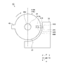
- FIG. 16 is a schematic diagram illustrating a schematic configuration of a cap opening and closing structure according to the fourth embodiment.
- FIG. 17 is a schematic diagram illustrating a schematic configuration of a cap opening and closing structure according to the fourth embodiment. 16 shows a state where the cap 4 is in the closed position, and FIG. 17 shows a state where the cap 4 is in the open position.
- the cap opening / closing structure 1 ⁇ / b> D and the charging connector 100 according to the fourth embodiment are different from the first embodiment in the configuration of the rotation support portion and the cap support portion.
- the hood portion 23 has a side surface 31C facing the outer peripheral surface 47 of the rotation support portion 410C of the cap 4, and a convex portion 29D formed on the side surface 31C.
- the side surface 31C is curved in an arc shape along the rotation direction of the rotation support portion 410C.
- the side surface 31C is formed so as to be opposed to the outer peripheral surface 47 of the rotation support portion 410C when the cap 4 is rotated.
- the side surface 31C and the outer peripheral surface 47 face each other in the radial direction of the rotation support portion 410C.
- the convex portion 29D is a first engaging portion or a second engaging portion, and protrudes from the side surface 31C in the radial direction of the rotation support portion 410C. As shown in FIG. 9, the convex portion 29 ⁇ / b> D includes a top surface 440 and two inclined surfaces 441.
- the rotation support portion 410C is integrated with the rotation support portion 41b.
- the rotation support portion 410C is accommodated in the accommodation portion 41c of the rotation support portion 41b.
- the rotation support portion 410C includes an accommodation portion 410c, an inlet damper spring 43B, an inlet damper 42C, an anti-rotation protrusion 45, and an insertion hole 46B.
- the accommodating portion 410c opens from the outer peripheral surface 47 of the rotation support portion 410C toward the radially outer side.
- the accommodating portion 410c accommodates the inlet damper spring 43B and the inlet damper 42C, and locks them with a known structure so as not to jump out.
- the accommodating portion 410c is configured such that the concave portion 44C of the inlet damper 42C protrudes from the outer peripheral surface 47 by the urging force of the inlet damper spring 43B.
- the inlet damper spring 43B is provided between the rotation support portion 410C and the inlet damper 42C, and biases the inlet damper 42C outward in the radial direction.
- the inlet damper spring 43 ⁇ / b> B biases the inlet damper 42 ⁇ / b> C in an engagement direction in which the concave portion 44 ⁇ / b> C and the convex portion 29 ⁇ / b> D are engaged in the open position of the cap 4.
- This engagement direction refers to a direction in which the concave portion 44 ⁇ / b> C and the convex portion 29 ⁇ / b> D can be engaged at the open position of the cap 4.
- the inlet damper 42C is supported so as to be movable in the radial direction with respect to the rotation support portion 410C.
- the concave portion 44C is a first engagement portion or a second engagement portion, and protrudes from the outer peripheral surface 47 of the rotation support portion 410C.
- the outer peripheral surface 47 is a surface facing the side surface 31 ⁇ / b> C of the hood portion 23. That is, the outer peripheral surface 47 of the rotation support portion 410C and the side surface 31C of the hood portion 23 face each other in the radial direction.
- the concave portion 44C engages with the convex portion 29D provided on the side surface 31C at the open position of the cap 4.
- the recess 44 ⁇ / b> C is formed in a substantially U shape whose cross-sectional shape viewed from the rotation axis direction opens in the radial direction.
- the recess 44C has two tips 44Ca and 44Cb at the opening. Of the tips 44Ca and 44Cb, the tip 44Ca on the rotation direction side from the closed position to the open position has a shape cut obliquely.
- the cut surface of the tip 44Ca is formed toward the rotation direction side. Further, the tip 44Ca is formed so that the length in the radial direction is shorter than the tip 44Cb.
- the recess 44C is preferably made of a supple metal that is not easily broken. Moreover, it is preferable that the corners of the tips 44Ca and 44Cb are chamfered.
- the opening operation from the closed position to the open position in the opening / closing structure 1D of the cap 4 will be described.
- the outer peripheral surface 47 of the rotation support portion 410 ⁇ / b> C and the side surface 31 ⁇ / b> C of the hood portion 23 face each other in the radial direction at the closed position of the cap 4.
- the inlet damper 42C is biased in the radial direction by the inlet damper spring 43B.
- the concave portion 44C of the inlet damper 42C and the convex portion 29D of the side surface 31C are in a disengaged state.
- the non-engaged state refers to a state in which neither of the tips 44Ca and 44Cb of the concave portion 44C is in contact with the two inclined surfaces 441 of the convex portion 29D.
- the recess 44C is urged in the radial direction by the inlet damper spring 43B, so that the tip 44Cb is in contact with the side surface 31C of the hood portion 23.
- the rotation support portion 410C rotates about the rotation axis. Rotation starts.
- the outer peripheral surface 47 of the rotation support portion 410C and the side surface 31C of the hood portion 23 are kept facing each other.
- the concave portion 44C maintains a non-engaged state with the convex portion 29D, and the tip 44Cb slides while contacting the side surface 31C of the hood portion 23 by the urging force of the inlet damper spring 43B.
- the outer peripheral surface 47 and the side surface 31C maintain engagement with each other in the radial direction, and the concave portion 44C starts to engage with the convex portion 29D.
- Migrate to The concave portion 44C approaches the convex portion 29D while the tip 44Cb slides on the side surface 31C, and the leading end 44Ca of the concave portion 44C is rotated in the rotation direction of the two inclined surfaces 441 of the convex portion 29D by the urging force of the inlet damper spring 43B. While sliding on the opposing inclined surface 441 (half-engaged state), engagement with the convex portion 29D is started.
- the half-engaged state refers to a state where the tip Ca of the concave portion 44C is in contact with one of the two inclined surfaces 441 of the convex portion 29D.
- the tip 44Ca gets over the top surface 440 of the projection 29D
- the tip 44Cb approaches the inclined surface 441 facing the rotation direction of the projection 29D.
- the bottom surface 290 of the concave portion 44C and the top surface 440 of the convex portion 29D gradually approach each other.
- the recess 44C is urged in the engagement direction by the inlet damper spring 43B, with the two tips 44Ca and 44Cb abutting against the inclined surface 441 of the projection 29D.
- the outer peripheral surface 47 of the rotation support portion 410C and the side surface 31C of the hood portion 23 do not come into contact with each other and maintain a facing state in the radial direction. In this state, the bottom surface 290 of the concave portion 44C and the top surface 440 of the convex portion 29D are closest to each other.
- the concave portion 44C urged by the inlet damper spring 43B is provided on the outer peripheral surface 47 of the rotation support portion 410C, and the convex portion is provided on the side surface 31C of the hood portion 23. 29D is provided. That is, with respect to the opening / closing structure 1C and the charging connector 100 described above, the engaging portion on the rotation support portion side is replaced by the concave portion 44C from the convex portion 44B, and the engaging portion on the hood portion 23 side is convex from the concave portion 29C. Since it is replaced with 29D, the same effects as those of the opening / closing structure 1C and the charging connector 100 of the third embodiment can be obtained.
- [Modification] 18 and 19 are schematic diagrams illustrating a schematic configuration of a cap opening and closing structure according to Modification 1 of Embodiment 3.
- FIG. FIG. 18 shows a state where the cap is in the closed position
- FIG. 19 shows a state where the cap is in the open position.
- the cap opening / closing structure 1 ⁇ / b> E and the charging connector 100 according to Modification 1 of Embodiment 3 include a hood when the cap 4 is in the closed position and when the cap 4 is rotated.
- abutting of the convex part 44B with respect to side surface 31D of the part 23 differs from Embodiment 3.
- the hood portion 23 includes a side surface 31D, a side surface 31Da, an inclined surface 31Db, and a recess 29C formed on the side surface 31D.
- the side surface 31D is a facing surface that faces the outer peripheral surface 47 of the rotation support portion 410B immediately before the opening position of the cap 4 and at the opening position of the cap 4.
- the side surface 31D and the outer peripheral surface 47 oppose each other in the radial direction of the rotation support portion 410B.
- the side surface 31D is connected to the inner side surface 291 that faces at least the rotational direction of the two inner side surfaces 291 of the recess 29C.
- the side surface 31Da is curved in an arc shape at least from the position facing the convex portion 44B in the closed position to the front of the concave portion 29C along the rotational direction of the rotational support portion 410B.
- the side surface 31Da and the outer peripheral surface 47 of the rotation support portion 410B are spaced apart in the radial direction of the rotation support portion 410B from the open position to the closed position in the rotation direction.
- the direction from the open position to the closed position is the closing direction
- the direction from the closed position to the opening position is the opening direction.
- the side surface 31Da and the outer peripheral surface 47 of the rotation support portion 410B facing each other are separated in the radial direction of the rotation support portion 410B in the closing direction.
- the side surface 31Da is connected to the inclined surface 31Db before the recess 29C.
- the inclined surface 31Db is connected to the side surface 31D while gradually reducing the distance from the outer peripheral surface 47 along the rotation direction.
- the separation interval between the side surface 31D and the outer peripheral surface 47 is narrower than the separation interval between the side surface 31Da and the outer peripheral surface 47.
- the opening operation from the closed position to the open position in the opening / closing structure 1E of the cap 4 will be described.
- the outer peripheral surface 47 of the rotation support portion 410 ⁇ / b> B and the side surface 31 ⁇ / b> D of the hood portion 23 face each other in the radial direction at the closed position of the cap 4.
- the inlet damper 42B is urged in the radial direction of the rotation support portion 410B by the inlet damper spring 43B.
- the convex portion 44B of the inlet damper 42B and the concave portion 29C of the side surface 31D are in a disengaged state.
- the non-engaged state refers to a state in which none of the pair of end portions 292A of the concave portion 29C is in contact with the two inclined surfaces 441 of the convex portion 44B.
- the convex portion 44B is urged in the radial direction by the inlet damper spring 43B, but does not contact the side surface 31Da of the hood portion 23.
- the rotation support portion 410B rotates about the rotation axis. Rotation starts.
- the outer peripheral surface 47 of the rotation support portion 410B and the side surface 31D of the hood portion 23 are kept facing each other.
- the convex portion 44B is spaced apart from the concave portion 29C and maintains a non-engaged state, and does not contact or slide on the side surface 31Da of the hood portion 23.
- the convex portion 44B starts to engage with the concave portion 29C while sliding against the inclined surface 31Db by the urging force of the inlet damper spring 43B.
- the top surface 440 of the convex portion 44B approaches the concave portion 29C while sliding on the inclined surface 31Db and the side surface 31D.
- the convex portion 44B starts to engage with the concave portion 29C while the inclined surface 441 facing the rotation direction slides on the end portion 292A of the concave portion 29C by the biasing force of the inlet damper spring 43B.
- the top surface 440 of the convex portion 44B and the bottom surface 290 of the concave portion 29C gradually approach each other.
- the convex portion 44B When the cap 4 reaches the open position, as shown in FIGS. 19 and 9, the convex portion 44B has two inclined surfaces 441 that abut against the two end portions 292A of the concave portion 29C and are engaged by the inlet damper spring 43B. Energized in the opposite direction.
- the outer peripheral surface 47 of the rotation support portion 410B and the side surface 31D of the hood portion 23 are kept in an opposed state in the radial direction without coming into contact with each other. In this state, the top surface 440 of the convex portion 44B and the bottom surface 290 of the concave portion 29C are closest to each other.
- the inlet damper spring 43B separates the convex portion 44B from the side surface 31D which is the opposing surface when the convex portion 44B and the concave portion 29C are disengaged. Energize to. Thereby, when the cap 4 is in the closed position and when the cap 4 is rotated, the contact of the convex portion 44B with the side surface 31D of the hood portion 23 is suppressed, and the convex portion 44B contacts and slides on the side surface 31D. The wear caused by this can be reduced.
- FIG. 20 and 21 are schematic views showing a schematic configuration of a cap opening and closing structure according to the second modification of the third embodiment.
- FIG. 20 shows a state where the cap is in the closed position
- FIG. 21 shows a state where the cap is in the open position.
- the opening / closing structure 1 ⁇ / b> F of the cap 4 according to the second modification of the third embodiment includes the rotation support portion 410 ⁇ / b> D when the cap 4 is in the closed position and when the cap 4 is rotated.
- the point which suppresses contact of the convex part 44B with respect to the outer peripheral surface 47 differs from Embodiment 3.
- FIG. 1 the opening / closing structure 1F of the cap 4 according to the modified example 2 is different from the opening / closing structure 1E of the cap 4 according to the modified example 1 in that the installation position of the configuration including the convex portion 44B and the installation position of the concave portion 44D are interchanged. It is a configuration.
- the hood portion 23 includes a side surface 31B, a housing portion 410c, an inlet damper spring 43B, and an inlet damper 42B.
- the side surface 31B is curved in an arc shape along the rotation direction of the rotation support portion 410D of the cap 4, and faces the outer peripheral surface 47 of the rotation support portion 410D.
- the side surface 31B is formed so as to maintain an opposing state with respect to the outer peripheral surface 47 of the rotation support portion 410D when the cap 4 is rotated.
- the side surface 31B and the outer peripheral surface 47 oppose each other in the radial direction of the rotation support portion 410B.
- the housing portion 410c opens from the side surface 31B of the hood portion 23 toward the turning shaft of the turning support portion 410D.
- the accommodating portion 410c accommodates the inlet damper spring 43B and the inlet damper 42B, and locks them with a known structure so as not to jump out.
- the accommodating portion 410c is configured such that the convex portion 44B of the inlet damper 42B protrudes from the side surface 31B by the urging force of the inlet damper spring 43B.
- the inlet damper spring 43B is provided between the hood portion 23 and the inlet damper 42B.
- the inlet damper spring 43B urges the inlet damper 42B toward the rotation shaft of the rotation support portion 410D, and the engagement portion 44B and the recess 44D are engaged in the engagement position in the open position of the cap 4. Energize.
- This engagement direction refers to a direction in which the convex portion 44B and the concave portion 44D can be engaged at the open position of the cap 4.
- the inlet damper 42B is supported movably in the direction toward the rotation axis of the rotation support portion 410D with respect to the hood portion 23.
- the convex portion 44 ⁇ / b> B is a first engaging portion or a second engaging portion, and protrudes from the side surface 31 ⁇ / b> B of the hood portion 23.
- the rotation support portion 410D is integrated with the rotation support portion 41b.
- the rotation support portion 410D is accommodated in the accommodation portion 41c of the rotation support portion 41b.
- the rotation support portion 410D includes a recess 44D, a rotation preventing projection 45, an insertion hole 46B, an outer peripheral surface 47, a partial outer peripheral surface 47a, and an inclined surface 47b.
- the concave portion 44D is a first engagement portion or a second engagement portion, and opens from the outer peripheral surface 47 of the rotation support portion 410D toward the radially outer side.
- the concave portion 44D engages with the convex portion 44B of the inlet damper 42B provided on the side surface 31B of the hood portion 23 at the open position of the cap 4.
- the outer peripheral surface 47 is a facing surface that faces the side surface 31B of the hood portion 23 immediately before the open position of the cap 4 and at the open position of the cap 4.
- the outer peripheral surface 47 and the side surface 31B are opposed to each other in the radial direction of the rotation support portion 410D.
- the outer peripheral surface 47 is connected to at least the inner side surface 291 facing in the rotational direction of the two inner side surfaces 291 of the recess 44D.
- the partial outer peripheral surface 47a is curved in an arc shape at least from the position facing the convex portion 44B in the closed position to the front of the concave portion 44D along the rotational direction of the rotational support portion 410D.
- the partial outer peripheral surface 47a and the side surface 31B are separated in the radial direction of the rotation support portion 410D from the open position to the closed position in the rotation direction.
- the direction from the open position to the closed position is the closing direction
- the direction from the closed position to the opening position is the opening direction.
- the partial outer peripheral surface 47a and the side surface 31B are separated in the radial direction of the rotation support portion 410D in the closing direction.
- the partial outer peripheral surface 47a is connected to the inclined surface 47b before the concave portion 44D.
- the inclined surface 47b is connected to the outer peripheral surface 47 while gradually reducing the distance from the side surface 31B along the rotation direction.
- the interval between the outer peripheral surface 47 and the side surface 31B is narrower than the interval between the partial outer peripheral surface 47a and the side surface 31B.
- the opening operation from the closed position to the open position in the opening / closing structure 1F of the cap 4 will be described.
- the outer peripheral surface 47 of the rotation support portion 410 ⁇ / b> D and the side surface 31 ⁇ / b> B of the hood portion 23 face each other in the radial direction at the closed position of the cap 4.
- the inlet damper 42B is urged toward the rotation shaft of the rotation support portion 410D by the inlet damper spring 43B.
- the convex portion 44B of the side surface 31B and the concave portion 44D of the rotation support portion 410D are in a disengaged state.
- the non-engagement state refers to a state where none of the pair of end portions 292A of the recess 44D is in contact with the two inclined surfaces 441 of the projection 44B.
- the convex portion 44B is biased in the radial direction by the inlet damper spring 43B, but does not contact the partial outer peripheral surface 47a of the rotation support portion 410D.
- the rotation support portion 410D rotates about the rotation axis. Rotation starts.
- the outer peripheral surface 47 of the rotation support portion 410D and the side surface 31B of the hood portion 23 are kept facing each other.
- the convex portion 44B is separated from the concave portion 44D and maintains the non-engaged state, and does not contact or slide on the partial outer peripheral surface 47a of the rotation support portion 410D.
- the convex portion 44B starts to engage with the concave portion 44D while sliding against the inclined surface 47b by the urging force of the inlet damper spring 43B.
- the top surface 440 of the convex portion 44B approaches the concave portion 44D while sliding on the inclined surface 47b and the outer peripheral surface 47.
- the convex portion 44B starts to engage with the concave portion 44D while the inclined surface 441 facing the rotation direction slides on the end portion 292A of the concave portion 44D by the biasing force of the inlet damper spring 43B.
- the top surface 440 of the convex portion 44B and the bottom surface 290 of the concave portion 44D gradually approach each other.
- the convex portion 44B When the cap 4 reaches the open position, as shown in FIGS. 21 and 9, the convex portion 44B has two inclined surfaces 441 that abut against the two end portions 292A of the concave portion 44D and are engaged by the inlet damper spring 43B. Energized in the opposite direction.
- the outer peripheral surface 47 of the rotation support portion 410D and the side surface 31B of the hood portion 23 are kept in an opposed state in the radial direction without coming into contact with each other. In this state, the top surface 440 of the convex portion 44B and the bottom surface 290 of the concave portion 44D are closest to each other.
- the opening / closing structure 1F of the cap 4 and the charging connector 100 having the above configuration can obtain the same effects as the above-described opening / closing structure 1E.
- the convex part may have the inclined surface.
- a convex portion 44E that does not have an inclined surface and a concave portion 29E that has an inclined surface may be combined.
- the convex portion 44E includes a top surface 440, a pair of end portions 443a, two outer surfaces 443 that are not inclined, and a pair of end portions 442B.
- the length of both ends of the top surface 440 in the rotation direction, that is, the length between the pair of end portions 443a and the length between the pair of end portions 442B are the same.
- the concave portion 29E includes a bottom surface 290, a pair of adjacent end portions 293a, two inclined surfaces 293, and a pair of separated end portions 292B.
- the bottom surface 290 is formed between the adjacent end portions 293a that are adjacent to each other in the rotation direction.
- the two inclined surfaces 293 are formed so as to extend in the engagement direction from a proximity end portion 293a at both ends of the bottom surface 290 in the rotation direction toward a pair of separation end portions 292B that are separated and opposed in the rotation direction. That is, the two inclined surfaces 293 are inclined so as to expand from the bottom surface 290 toward the engagement direction (the direction of the dotted arrow in the figure).
- the two inclined surfaces 293 are formed such that, at the open position of the cap 4, the bottom surface 290 is not in contact with the top surface 440 and the convex portion 44E is engaged with the concave portion 29E.
- the rotation support part 41b is provided with the inlet damper 42A which has the convex part 44A, and the inlet damper spring 43A which urges
- 26 A of 1st support parts may be the structure provided with the inlet damper which has a convex part, and the inlet spring which urges
- a recessed part may be provided in the rotation support part 41b side, and a convex part may be provided in the 1st support part 26A side.
- the charging connector on the vehicle side has been described as an application example of the cap opening / closing structure. However, it may be applied to the power feeding connector on the vehicle side.
- the power feeding connector may be the same as the charging connector and may be used in combination, or may have a different form from the charging connector.
- the end portions 292A and 442B are formed at right angles, but may be chamfered.
- the pair of inclined surfaces of the convex portions or the concave portions in the first to fourth embodiments and the modified examples may have not only a planar shape but also a spherical shape having symmetry.
- the convex portion may be hemispherical, or the convex portion may have a semicircular cross-sectional shape.
- the cutting surface of the tip 44Ca is formed toward the rotation direction side, but is not limited thereto, and the cutting surface is also formed in the direction opposite to the rotation direction side. May be.
- the side surface 31Da may not be formed to face the outer peripheral surface 47 of the rotation support portion 410B. Moreover, the partial outer peripheral surface 47a does not need to be formed so as to face the side surface 31B of the hood portion 23.
Landscapes
- Engineering & Computer Science (AREA)
- Mechanical Engineering (AREA)
- Transportation (AREA)
- Power Engineering (AREA)
- Sustainable Energy (AREA)
- Sustainable Development (AREA)
- Life Sciences & Earth Sciences (AREA)
- Chemical & Material Sciences (AREA)
- Combustion & Propulsion (AREA)
- Connector Housings Or Holding Contact Members (AREA)
- Cooling, Air Intake And Gas Exhaust, And Fuel Tank Arrangements In Propulsion Units (AREA)
- Electric Propulsion And Braking For Vehicles (AREA)
- Arrangement Or Mounting Of Propulsion Units For Vehicles (AREA)
Abstract
キャップ4の開閉構造1Aは、インレットダンパー42Aの回動軸方向の面48と、第一支持部26Aの側面30Aとが、キャップ4の回動時において対向状態を維持するように構成される。面48には凸部44Aが設けられ、側面30Aには凹部29Aが設けられており、凸部44Aと凹部29Aとが開位置において係合するように構成する。インレットダンパースプリング43Aが、凸部44Aと凹部29Aとが開位置において係合し、かつ、凸部44Aと凹部29Aとが非係合状態において、対向する側面30Aに当接するように付勢する。凸部44Aが、開位置において、回動方向に対向する2つの傾斜面441が凹部29Aの端部292Aに当接する。
Description
本発明は、キャップの開閉構造および充電用コネクタに関する。
従来、電気自動車(EV)、プラグインハイブリッド自動車(PHEV)などの車両では、充電用コネクタが接続される接続部を覆うようにキャップが開閉可能に設けられた車両側充電用コネクタが使用されている。車両側充電用コネクタでは、スプリングなどの付勢部材がキャップを開く方向に向けて付勢している。キャップが閉状態の場合、キャップがハウジングに係止されているが、操作者がこの係止を解除すると、付勢部材の付勢力によってキャップが開くようになっている。
このような車両側充電用コネクタでは、キャップを付勢する付勢部材の付勢力が強いとキャップが勢いよく開きすぎて、キャップ自体やキャップの開閉構造の耐久性が低下するおそれがあることから、キャップを緩やかに動作させる開閉構造が提案されている(例えば、特許文献1~4参照)。
ところで、上記特許文献1~4に記載された車両側充電用コネクタでは、高価な回転式のオイルダンパーを用いることなくキャップが開くときの勢いを抑制しているが、いずれもキャップを緩やかに開かせるための構造が複雑で改善の余地がある。
本発明は、簡単な構成で、キャップが開くときの勢いを抑制し、キャップが開ききったときのばたつきを抑えることができるキャップの開閉構造および充電用コネクタを提供することを目的とする。
上記目的を達成するために、本発明に係るキャップの開閉構造は、車両外部の接続対象と、開口部を介して電気的に接続される接続部が設けられるハウジングと、一端の回動支持部において前記ハウジングに対して回動自在に支持され、かつ閉位置において前記開口部を閉塞し、開位置において前記開口部を介して前記接続部を前記車両外部に露出するキャップと、前記キャップを前記閉位置から前記開位置に向かう回動軸回りに回動するように付勢する第一付勢部材と、前記ハウジングおよび前記キャップにそれぞれ形成され、かつ前記キャップの回動時において対向状態を維持する一対の第一対向面および第二対向面と、前記第一対向面および前記第二対向面にそれぞれ設けられる第一係合部および第二係合部と、前記第一係合部および前記第二係合部のうち一方の係合部を、一方の前記係合部と他方の前記係合部とが前記開位置において係合することができる係合方向に付勢する第二付勢部材と、を備え、前記第一係合部および前記第二係合部は、一方の前記係合部が凸部を有し、他方の前記係合部が前記開位置において前記第二付勢部材により前記凸部が係合する凹部を有し、前記凸部および前記凹部のうち少なくとも一方は、回動方向に対向する2つの傾斜面を有し、2つの前記傾斜面は、前記開位置において前記凸部および前記凹部の近接対向する近接端部から離間対向する離間端部に向かって前記係合方向に拡張して形成されることを特徴とする。
また、上記キャップの開閉構造において、2つの前記傾斜面は、前記開位置において前記近接端部が非接触状態で、前記凸部が前記凹部に係合するように形成されることが好ましい。
また、上記キャップの開閉構造において、前記第一対向面および前記第二対向面は、回動軸において対向するものであり、一方の前記係合部は、前記回動支持部に対して回動軸方向に移動自在に支持され、前記第二付勢部材は、一方の前記係合部と前記回動支持部または前記ハウジングとの間に設けられ、一方の前記係合部を前記回動軸方向のうち、前記第一対向面または前記第二対向面のうちの一方の対向面側に付勢することが好ましい。
また、上記キャップの開閉構造において、前記第一対向面および前記第二対向面は、前記回動支持部の半径方向において対向するものであり、一方の前記係合部は、前記回動支持部に対して半径方向に移動自在に支持され、前記第二付勢部材は、一方の前記係合部と前記回動支持部または前記ハウジングとの間に設けられ、一方の前記係合部を前記半径方向外側に、前記第一対向面または前記第二対向面側に付勢することが好ましい。
また、上記キャップの開閉構造において、前記第二付勢部材は、前記第一係合部および前記第二係合部の非係合状態において、一方の前記係合部を対向する前記対向面と当接させることが好ましい。
また、上記キャップの開閉構造において、前記第一対向面および前記第二対向面は、前記回動方向に前記開位置から前記閉位置に向かって、前記回動支持部の半径方向に離間することが好ましい。
上記目的を達成するために、本発明に係る充電用コネクタは、請求項1~6のいずれか1項に記載のキャップの開閉構造と、車両外部の充電用コネクタとの間で電気的に接続される接続部とを有する。
本発明によれば、キャップが開くときの勢いを抑制し、キャップが開ききったときのばたつきを抑えることができる。
以下に、本発明に係る実施形態を図面に基づいて詳細に説明する。なお、下記の実施形態により本発明が限定されるものではない。また、下記の実施形態における構成要素には、いわゆる当業者が置換可能、かつ、容易なもの、あるいは実質的に同一のものが含まれる。また、下記の実施形態における構成要素は、発明の要旨を逸脱しない範囲で、種々の省略、置き換え、変更を行うことができる。
[実施形態1]
図1~図9を参照して、実施形態1に係るキャップの開閉構造および充電用コネクタについて説明する。図1は、実施形態1に係るキャップの開閉構造が適用された充電用コネクタの概略構成を示す斜視図である。図2は、実施形態1に係るキャップの開閉構造が適用された充電用コネクタの概略構成を示す側面図である。図3は、実施形態1に係るキャップの開閉構造の概略構成を示す分解斜視図である。図4は、実施形態1に係るキャップの開閉構造におけるインレットダンパーの概略構成を示す側面図である。図5は、実施形態1に係るキャップの開閉構造におけるインレットダンパー支持部の概略構成を示す部分斜視図である。図6は、図1におけるA-A断面図である。図7は、実施形態1に係るキャップの開閉構造の概略構成を示す部分断面図である。図8は、実施形態1に係るキャップの開閉構造の概略構成を示す部分断面図である。図9は、キャップの開閉構造の凸部と凹部の係合動作を示す模式図である。なお、図1はキャップが開位置にある状態、図2はキャップが閉位置にある状態を示す。図5は、キャップを支持するハウジングのキャップ支持部を示す。図6は、キャップを開いた状態の充電用コネクタにおけるキャップの回動支持部の断面を示す。図7はキャップが閉位置にある状態、図8はキャップが開位置にある状態を示す。
図1~図9を参照して、実施形態1に係るキャップの開閉構造および充電用コネクタについて説明する。図1は、実施形態1に係るキャップの開閉構造が適用された充電用コネクタの概略構成を示す斜視図である。図2は、実施形態1に係るキャップの開閉構造が適用された充電用コネクタの概略構成を示す側面図である。図3は、実施形態1に係るキャップの開閉構造の概略構成を示す分解斜視図である。図4は、実施形態1に係るキャップの開閉構造におけるインレットダンパーの概略構成を示す側面図である。図5は、実施形態1に係るキャップの開閉構造におけるインレットダンパー支持部の概略構成を示す部分斜視図である。図6は、図1におけるA-A断面図である。図7は、実施形態1に係るキャップの開閉構造の概略構成を示す部分断面図である。図8は、実施形態1に係るキャップの開閉構造の概略構成を示す部分断面図である。図9は、キャップの開閉構造の凸部と凹部の係合動作を示す模式図である。なお、図1はキャップが開位置にある状態、図2はキャップが閉位置にある状態を示す。図5は、キャップを支持するハウジングのキャップ支持部を示す。図6は、キャップを開いた状態の充電用コネクタにおけるキャップの回動支持部の断面を示す。図7はキャップが閉位置にある状態、図8はキャップが開位置にある状態を示す。
以下の説明において、図示のX方向は、実施形態における充電用コネクタの幅方向であり、キャップの回動軸方向に直交する方向である。Y方向は、実施形態における充電用コネクタのキャップの回動軸方向であり、X方向と直交する方向である。Z方向は、実施形態における充電用コネクタの上下方向であり、X方向およびY方向と直交する方向である。なお、Z方向は、充電用コネクタの上下方向であって鉛直方向に限らない。
実施形態1に係るキャップの開閉構造1Aが適用された充電用コネクタ100について説明する。図1および図2に示す充電用コネクタ100は、例えば、電気自動車(EV)、プラグインハイブリッド自動車(PHEV)などの車両に設けられ、当該車両に搭載されたバッテリを充電するための車両外部の充電用コネクタと電気的に接続されるものである。充電用コネクタ100は、当該車両の車体パネルなどに固定される。キャップの開閉構造1Aは、ハウジング2と、トーションスプリング3と、キャップ4とで構成される。
ハウジング2は、車両外部の接続対象と、開口部22aを介して電気的に接続される接続部22bを有する。車両外部の接続対象は、例えば充電用コネクタである。より詳細には、ハウジング2は、車体取付部21と、ハウジング本体22と、フード部23と、ヒンジピン24と、キャップ支持部25と、キャップロック部28とを備える。
車体取付部21は、合成樹脂製で略矩形の板状部材から成り、四隅に車体パネル(不図示)への取付孔である貫通孔21aが設けられている。車体取付部21は、4つの貫通孔21aにボルト(不図示)を挿通して車体パネルに締め付けることで当該車体パネルに固定される。
ハウジング本体22は、合成樹脂製で円柱状の部材から成り、車体取付部21の略中央から上下方向に延設される。ハウジング本体22は、車両外部に向かう上方向に、開口部22aを含む接続部22bを備える。接続部22bは、車両外部の充電用コネクタと開口部22aを介して電気的に接続される。接続部22bの内部には、車両内部のバッテリ(不図示)から延びる電線(不図示)に接続された端子金具(不図示)が収容されている。
フード部23は、合成樹脂製で略円筒形状を有し、車体取付部21よりもZ方向の上側に接続部22bを外周から覆うように設けられている。フード部23は、その外周面に、キャップ支持部25と、キャップロック部28とが設けられている。
ヒンジピン24は、金属製の細長い棒状部材であり、Y方向すなわちキャップ4の回動軸方向にキャップ支持部25を介してトーションスプリング3およびキャップ4に挿通される。ヒンジピン24は、その回動軸を中心にして、キャップ4をハウジング2に対して回動させる。
キャップ支持部25は、ヒンジピン24によりキャップ4を回動自在に支持するものである。キャップ支持部25は、間隔を空けて対向する位置に設けられた一対の第一支持部26Aと第二支持部27とで構成される。キャップ支持部25は、第一支持部26Aおよび第二支持部27によりキャップ4を回動軸方向から狭持する。第一支持部26Aは、第二支持部27と対向する側面30Aに、ヒンジピン24が挿通する挿通孔26aと、凹部29Aとを有する。第二支持部27は、ヒンジピン24が挿通される挿通孔27aを有する。
凹部29Aは、第一係合部または第二係合部であり、キャップ4の回動軸方向に凹み、当該回動軸方向と直交する上下方向(Z方向)に延在して溝状に形成される。凹部29Aは、図9に示すように、底面290と、一対の端部290aと、底面290の両端にある端部290aから垂直に立ち上がる一対の内側面291と、一対の端部292Aとで構成される。底面290は、回動方向に対向する端部290a間に形成される。この端部292Aは、内側面291と側面30Aとが直角に接する位置にある。
キャップロック部28は、キャップ支持部25の反対側のフード部23の外周面に設けられ、キャップ4を閉位置で係止する係止機構である。
トーションスプリング3は、第一付勢部材であり、例えば金属製のねじりコイルばねである。トーションスプリング3は、キャップ4を閉位置から開位置に向かう回動軸回りに回動するように付勢する。トーションスプリング3は、キャップ4の回動支持部41bと共に、第一支持部26Aと第二支持部27との間に配置され、内周側にヒンジピン24が挿通される。トーションスプリング3の一端は、図5~図8に示すハウジング2のフード部23の外周面31Aに係止され、他端は、キャップ4の回動支持部41bの外側面41dに係止される。
キャップ4は、閉位置において開口部22aを閉塞し、開位置において開口部22aを介して接続部22bを車両外部に露出するものである。キャップ4は、合成樹脂製のキャップ本体41と、合成樹脂製のインレットダンパー42Aと、金属製のインレットダンパースプリング43Aとを含んで構成される。
キャップ本体41は、蓋部41aと、回動支持部41bと、収容部41cと、ハウジング2に対向する外側面41dと、回り止め部41eとを含んで構成される。蓋部41aは、略円形の板状部材から成り、キャップ4が閉位置において開口部22aを覆うように閉塞する一方、キャップ4が開位置において開口部22aを介して接続部22bを露出する。回動支持部41bは、蓋部41aの一端に設けられ、ハウジング2に対して回動自在に支持される。収容部41cは、回動支持部41bの回動軸方向に開口し、一方の開口から順にインレットダンパースプリング43A、インレットダンパー42Aを収容し、他方の開口からヒンジピン24を挿通する。外側面41dは、回動支持部41bの回動方向に沿って円弧状に湾曲、すなわちキャップ4の回動軸を中心とする円弧(円弧面)に沿って湾曲している。回り止め部41eは、回動支持部41bの外側面41dに形成され、回動軸方向に延在する突起であり、キャップ4が開位置においてフード部23の外周面31Aに当接し、キャップ4の回動を抑止するものである。
インレットダンパー42Aは、キャップ4の回動支持部41bに対して回動軸方向に移動自在に支持される。インレットダンパー42Aは、円筒形状を有し、インレットダンパースプリング43Aを収容した状態で、回動支持部41bの収容部41cに収容される。インレットダンパー42Aは、インレットダンパースプリング43Aにより回動軸方向に付勢される。インレットダンパー42Aは、図3および図4に示すように、凸部44Aと、回り止め突起部45と、挿通孔46Aとを含んで構成される。
凸部44Aは、第一係合部または第二係合部であり、インレットダンパー42Aの回動軸方向の一方の面48から突出し、回動軸方向と直交する半径方向に延在する。面48は、第一支持部26Aの側面30Aに対する対向面である。すなわち、インレットダンパー42Aの面48と第一支持部26Aの側面30Aとは回動軸方向において対向している。凸部44Aは、側面30Aに設けられた凹部29Aに対して、キャップ4の開位置において係合する。凸部44Aは、図9に示すように、頂面440と、一対の近接端部441aと、2つの傾斜面441と、一対の離間端部442Aとを有する。頂面440は、回動方向に近接対向する近接端部441a間に形成される。2つの傾斜面441は、頂面440の回動方向の両端にある近接端部441aから、回動方向に離間対向する一対の離間端部442Aに向かって係合方向に拡張して形成される。すなわち、2つの傾斜面441は、頂面440から係合方向(図示の点線矢印の方向)に向かって拡がるように傾斜する。また、2つの傾斜面441は、キャップ4の開位置において、頂面440が底面290に非接触状態で、凸部44Aが凹部29Aに係合するように形成される。ここで凸部44Aが凹部29Aに係合するとは、一対の端部292Aが2つの傾斜面441に当接している状態であり、この状態を係合状態とする。
回り止め突起部45は、外周面47に形成され、回動軸方向に延在して設けられている。回り止め突起部45は、インレットダンパー42Aが収容部41cに収容する際に、収容部41cの内周面に形成された凹部と係合する。
挿通孔46Aは、回動軸方向に貫通し、回動軸方向の一方の部分の内径が他方の部分の内径よりも小径となる段付き形状を有する。挿通孔46Aは、インレットダンパースプリング43Aを収容し、ヒンジピン24が挿通される。
インレットダンパースプリング43Aは、第二付勢部材であり、例えば金属製の圧縮コイルばねである。インレットダンパースプリング43Aは、インレットダンパー42Aと共に、キャップ4の回動軸の同軸上に収容部41cに収容され、内周側にヒンジピン24が挿通される。インレットダンパースプリング43Aは、回動支持部41bとインレットダンパー42Aとの間に設けられ、インレットダンパー42Aの回動軸方向の面48を回動軸方向のうち、第一支持部26Aの側面30A側に向けて付勢する。すなわち、インレットダンパースプリング43Aは、係合方向に付勢する。この係合方向は、2つの係合部である凸部44Aと凹部29Aとがキャップ4の開位置において係合することができる方向をいう。
次に、キャップ4の開閉構造1Aにおける閉位置から開位置までの開動作について説明する。図7に示すように、キャップ4およびハウジング2は、キャップ4の閉位置において、インレットダンパー42Aの回動軸方向の面48と第一支持部26Aの側面30Aとが回動軸方向に対向する。面48は、インレットダンパースプリング43Aにより回動軸方向に付勢される。面48の凸部44Aと側面30Aの凹部29Aは非係合状態である。非係合状態は、凹部29Aの一対の端部292Aのいずれも凸部44Aの2つの傾斜面441に当接していない状態をいう。凸部44Aは、インレットダンパースプリング43Aにより回動軸方向に付勢され、第一支持部26Aの側面30Aに当接している。
キャップロック部28による係止が解放され、キャップ4が閉位置から開位置に向けてトーションスプリング3の付勢力により回動軸回りに回動し始めると、インレットダンパー42Aが回動軸回りに回動を開始する。キャップ4の回動時において、インレットダンパー42Aの回動軸方向の面48および第一支持部26Aの側面30Aは、対向状態を維持している。凸部44Aは、凹部29Aとの間で非係合状態を維持し、インレットダンパースプリング43Aの付勢力により第一支持部26Aの側面30Aに当接しながら摺動する。
キャップ4が開位置に近づくと、面48と側面30Aとは回動軸方向に対向状態を維持しながら、凸部44Aが凹部29Aに対して係合を開始し、非係合状態から係合状態へ移行する。凸部44Aは、図9に示すように、その頂面440が側面30Aを摺動しながら凹部29Aに近づき、インレットダンパースプリング43Aの付勢力により、回動方向に対向する傾斜面441が凹部29Aの端部292Aに摺動しながら(半係合状態)、凹部29Aに対して係合を始める。凸部44Aの頂面440と、凹部29Aの底面290とが徐々に近接する。半係合状態は、凹部29Aの一対の端部292Aの一方が凸部44Aの2つの傾斜面441の一方に当接している状態をいう。
キャップ4が開位置に到達すると、図8に示すように、凸部44Aは、2つの傾斜面441がいずれも凹部29Aの2つの端部292Aに当接し、インレットダンパースプリング43Aにより係合方向に付勢される。キャップ4が閉位置において、インレットダンパー42Aの回動軸方向の面48と第一支持部26Aの側面30Aは、当接することなく、回動軸方向に対向状態を維持する。この状態において、凸部44Aの頂面440と凹部29Aの底面290とは最も近接する。
以上説明したキャップ4の開閉構造1Aおよび充電用コネクタ100によれば、キャップ4の開位置において、凸部44Aを凹部29Aに押し当てるようにして凸部44Aと凹部29Aとが係合するため、キャップ4が開ききったときのばたつきを抑えることができる。また、凸部44Aが、凹部29Aと非係合状態において、対向する側面30Aに当接するように付勢されるので、凸部44Aと側面30Aとが当接して摺動し、キャップ4が開くときに勢いを抑制することができる。さらに、樹脂部材とスプリングのみで構成され、単純な構造であることから、コストダウンを図ることができる。さらに、金属製のインレットダンパースプリング43Aが外部に露出しない構造であることが、水分などの液体の浸入を抑制し、凍結などによる耐久性の低下を抑制することができる。
[実施形態2]
次に、図10~図13を参照して、実施形態2に係るキャップの開閉構造および充電用コネクタ100について説明する。図10および図11は、実施形態2に係るキャップの開閉構造の概略構成を示す模式図である。図12は、実施形態2に係るキャップの開閉構造におけるインレットダンパーの概略構成を示す側面図である。図13は、実施形態2におけるハウジングの第一支持部の概略構成を示す側面図である。なお、図10は、キャップが閉位置にある状態、図11は、キャップが開位置にある状態を示す。図12は、回動支持部を回動軸方向から視た図であり、図13は、ハウジングの第一支持部を回動軸方向から視た図である。
次に、図10~図13を参照して、実施形態2に係るキャップの開閉構造および充電用コネクタ100について説明する。図10および図11は、実施形態2に係るキャップの開閉構造の概略構成を示す模式図である。図12は、実施形態2に係るキャップの開閉構造におけるインレットダンパーの概略構成を示す側面図である。図13は、実施形態2におけるハウジングの第一支持部の概略構成を示す側面図である。なお、図10は、キャップが閉位置にある状態、図11は、キャップが開位置にある状態を示す。図12は、回動支持部を回動軸方向から視た図であり、図13は、ハウジングの第一支持部を回動軸方向から視た図である。
実施形態2に係るキャップ4の開閉構造1Bおよび充電用コネクタ100は、図10~図13に示すように、回動支持部およびキャップ支持部の構成が実施形態1と異なる。以下では、上述した実施形態1と同様の構成要素には共通の符号を付すと共に、共通する構成、作用、効果については、重複した説明はできるだけ省略する(以下、同様。)。
ハウジング2において、第一支持部26Bは、第二支持部27と対向する側面30Bに、ヒンジピン24が挿通する挿通孔26aと、凹部29Bとを有する。
凹部29Bは、第一係合部または第二係合部であり、キャップ4の回動軸方向に凹むものである。凹部29Bは、図9に示すように、底面290と、内側面291と、端部292Aとで構成される。
キャップ4において、回動支持部410Aは、回動支持部41bと一体化されたものである。回動支持部410Aは、回動支持部41bの収容部41cに収容される。回動支持部410Aは、収容部410cと、インレットダンパースプリング43Bと、インレットダンパー42Bと、回り止め突起部45と、挿通孔46Bとを含んで構成される。
収容部410cは、回動軸から半径方向に外側に向かう位置に設けられ、回動支持部410Aの面48から回動軸方向に開口する。収容部410cは、インレットダンパースプリング43B、インレットダンパー42Bを収容し、これらを外部に飛び出さないように公知の構造で係止する。収容部410cは、インレットダンパースプリング43Bの付勢力によりインレットダンパー42Bの凸部44Bが面48から突出するように構成される。
インレットダンパースプリング43Bは、第二付勢部材であり、例えば金属製で小径の圧縮コイルばねである。インレットダンパースプリング43Bは、インレットダンパー42Bと共に収容部410cに収容される。インレットダンパースプリング43Bは、インレットダンパー42Bと回動支持部410Aとの間に設けられ、回動支持部410Aの回動軸方向の面48を回動軸方向のうち、第一支持部26Bの側面30B側に向けて付勢する。インレットダンパースプリング43Bは、インレットダンパー42Bを、凸部44Bと凹部29Bとがキャップ4の開位置において係合する係合方向に付勢する。この係合方向は、2つの係合部である凸部44Bと凹部29Bとがキャップ4の開位置において係合することができる方向をいう。
インレットダンパー42Bは、回動支持部410Aに対して回動軸方向に移動自在に支持される。インレットダンパー42Bは、円筒形状を有し、回動支持部410Aの収容部410cに収容される。インレットダンパー42Bは、一端に凸部44Bを有する。
凸部44Bは、第一係合部または第二係合部であり、回動支持部410Aの回動軸方向の面48から突出する。面48は、第一支持部26Bの側面30Bに対する対向面である。すなわち、回動支持部410Aの面48と第一支持部26Bの側面30Bとは回動軸方向において対向する。凸部44Bは、側面30Bに設けられた凹部29Bに対して、キャップ4の開位置において係合する。凸部44Bは、図9に示すように、頂面440と、2つの傾斜面441とで構成される。
挿通孔46Bは、回動軸方向に貫通し、回動軸方向の一方の部分の内径と他方の部分の内径とが同径となる。挿通孔46Bは、ヒンジピン24が挿通される。
次に、キャップ4の開閉構造1Bにおける閉位置から開位置までの開動作について説明する。図10に示すように、キャップ4およびハウジング2は、キャップ4の閉位置において、回動支持部410Aの回動軸方向の面48と第一支持部26Bの側面30Bとが回動軸方向に対向する。インレットダンパー42Bは、インレットダンパースプリング43Bにより回動軸方向に付勢される。インレットダンパー42Bの凸部44Bと側面30Bの凹部29Bは非係合状態である。非係合状態は、凹部29Bの一対の端部292Aのいずれも凸部44Bの2つの傾斜面441に当接していない状態をいう。凸部44Bは、インレットダンパースプリング43Bにより回動軸方向に付勢され、第一支持部26Bの側面30Bに当接している。
キャップロック部28による係止が解放され、キャップ4が閉位置から開位置に向けてトーションスプリング3の付勢力により回動軸回りに回動し始めると、回動支持部410Aが回動軸回りに回動を開始する。キャップ4の回動時において、回動支持部410Aの回動軸方向の面48および第一支持部26Bの側面30Bは、対向状態を維持している。凸部44Bは、凹部29Bとの間で非係合状態を維持し、インレットダンパースプリング43Bの付勢力により第一支持部26Bの側面30Bに当接しながら摺動する。
キャップ4が開位置に近づくと、面48と側面30Bとは回動軸方向に対向状態を維持しながら、凸部44Bが凹部29Bに対して係合を開始し、非係合状態から係合状態へ移行する。凸部44Bは、図9に示すように、その頂面440が側面30Bを摺動しながら凹部29Bに近づき、インレットダンパースプリング43Bの付勢力により、回動方向に対向する傾斜面441が凹部29Bの端部292Aに摺動しながら(半係合状態)、凹部29Bに対して係合を始める。凸部44Bの頂面440と、凹部29Bの底面290とが徐々に近接する。半係合状態は、凹部29Bの一対の端部292Aの一方が凸部44Bの2つの傾斜面441の一方に当接している状態をいう。
キャップ4が開位置に到達すると、図11に示すように、凸部44Bは、2つの傾斜面441がいずれも凹部29Bの2つの端部292Aに当接し、インレットダンパースプリング43Bにより係合方向に付勢される。キャップ4が閉位置において、回動支持部410Aの面48と第一支持部26Bの側面30Bは、当接することなく、回動軸方向に対向状態を維持する。この状態において、凸部44Bの頂面410と凹部29Bの底面290とは最も近接する。
以上説明したキャップ4の開閉構造1Bおよび充電用コネクタ100によれば、キャップ4の開位置において、凸部44Bを凹部29Bに押し当てるようにして凸部44Bと凹部29Bとが係合するため、キャップ4が開ききったときのばたつきを抑えることができる。また、凸部44Bが、凹部29Bと非係合状態において、対向する側面30Bに当接するように付勢されるので、凸部44Bと側面30Bとが当接して摺動し、キャップ4が開くときの勢いを抑制することができる。さらに、樹脂部材とスプリングのみで構成され、単純な構造であることから、コストダウンを図ることができる。さらに、金属製のインレットダンパースプリング43Bが外部に露出しない構造であることから、水分などの液体の浸入を抑制し、凍結などによる耐久性の低下を抑制することができる。
[実施形態3]
次に、図14、図15を参照して、実施形態3に係るキャップの開閉構造について説明する。図14は、実施形態3に係るキャップの開閉構造の概略構成を示す模式図である。図15は、実施形態3に係るキャップの開閉構造の概略構成を示す模式図である。なお、図14はキャップが閉位置にある状態、図15はキャップが開位置にある状態を示す。
次に、図14、図15を参照して、実施形態3に係るキャップの開閉構造について説明する。図14は、実施形態3に係るキャップの開閉構造の概略構成を示す模式図である。図15は、実施形態3に係るキャップの開閉構造の概略構成を示す模式図である。なお、図14はキャップが閉位置にある状態、図15はキャップが開位置にある状態を示す。
実施形態3に係るキャップ4の開閉構造1Cおよび充電用コネクタ100は、図14、図15に示すように、回動支持部およびキャップ支持部の構成が実施形態1と異なる。
ハウジング2において、フード部23は、キャップ4の回動支持部410Bの外周面47と対向する側面31Bと、側面31Bに形成された凹部29Cとを有する。側面31Bは、回動支持部410Bの回動方向に沿って円弧状に湾曲している。側面31Bは、回動支持部410Bの外周面47に対して、キャップ4の回動時において対向状態を維持するように形成される。側面31Bおよび外周面47は、回動支持部410Bの半径方向において対向する。
凹部29Cは、第一係合部または第二係合部であり、側面31Bから回動支持部410Bの半径方向外側に凹むものである。凹部29Cは、図9に示すように、底面290と、内側面291と、端部292Aとで構成される。
キャップ4において、回動支持部410Bは、回動支持部41bと一体化されたものである。回動支持部410Bは、回動支持部41bの収容部41cに収容される。回動支持部410Bは、収容部410cと、インレットダンパースプリング43Bと、インレットダンパー42Bと、回り止め突起部45と、挿通孔46Bとを含んで構成される。
収容部410cは、回動支持部410Bの外周面47から半径方向に開口する。収容部410cは、インレットダンパースプリング43B、インレットダンパー42Bを収容し、これらを外部に飛び出さないように公知の構造で係止する。収容部410cは、インレットダンパースプリング43Bの付勢力によりインレットダンパー42Bの凸部44Bが外周面47から突出するように構成される。
インレットダンパースプリング43Bは、回動支持部410Bとインレットダンパー42Bとの間に設けられ、インレットダンパー42Bを半径方向外側に付勢する。インレットダンパースプリング43Bは、インレットダンパー42Bを、凸部44Bと凹部29Cとがキャップ4の開位置において係合する係合方向に付勢する。この係合方向は、凸部44Bと凹部29Cとがキャップ4の開位置において係合することができる方向をいう。
インレットダンパー42Bは、回動支持部410Bに対して半径方向に移動自在に支持される。凸部44Bは、第一係合部または第二係合部であり、回動支持部410Bの外周面47から突出する。外周面47は、フード部23の側面31Bに対する対向面である。すなわち、回動支持部410Bの外周面47とフード部23の側面31Bとは半径方向において対向する。凸部44Bは、側面31Bに設けられた凹部29Cに対して、キャップ4の開位置において係合する。
次に、キャップ4の開閉構造1Cにおける閉位置から開位置までの開動作について説明する。図14に示すように、キャップ4およびハウジング2は、キャップ4の閉位置において、回動支持部410Bの外周面47とフード部23の側面31Bとが半径方向に対向する。インレットダンパー42Bは、インレットダンパースプリング43Bにより半径方向に付勢される。インレットダンパー42Bの凸部44Bと側面31Bの凹部29Cは非係合状態である。非係合状態は、凹部29Cの一対の端部292Aのいずれも凸部44Bの2つの傾斜面441に当接していない状態をいう。凸部44Bは、インレットダンパースプリング43Bにより半径方向に付勢され、フード部23の側面31Bに当接している。
キャップロック部28による係止が解放され、キャップ4が閉位置から開位置に向けてトーションスプリング3の付勢力により回動軸回りに回動し始めると、回動支持部410Bが回動軸回りに回動を開始する。キャップ4の回動時において、回動支持部410Bの外周面47およびフード部23の側面31Bは、対向状態を維持している。凸部44Bは、凹部29Cとの間で非係合状態を維持し、インレットダンパースプリング43Bの付勢力によりフード部23の側面31Bに当接しながら摺動する。
キャップ4が開位置に近づくと、外周面47と側面31Bとは半径方向に対向状態を維持しながら、凸部44Bが凹部29Cに対して係合を開始し、非係合状態から係合状態へ移行する。凸部44Bは、図9に示すように、その頂面440が側面31Bを摺動しながら凹部29Cに近づき、インレットダンパースプリング43Bの付勢力により、回動方向に対向する傾斜面441が凹部29Cの端部292Aに摺動しながら(半係合状態)、凹部29Cに対して係合を始める。凸部44Bの頂面440と、凹部29Cの底面290とが徐々に近接する。半係合状態は、凹部29Bの一対の端部292Aの一方が凸部44Bの2つの傾斜面441の一方に当接している状態をいう。
キャップ4が開位置に到達すると、図15および図9に示すように、凸部44Bは、2つの傾斜面441がいずれも凹部29Cの2つの端部292Aに当接し、インレットダンパースプリング43Bにより係合方向に付勢される。キャップ4が閉位置において、回動支持部410Bの外周面47とフード部23の側面31Bは、当接することなく、半径方向に対向状態を維持する。この状態において、凸部44Bの頂面440と凹部29Cの底面290とは最も近接する。
以上説明したキャップ4の開閉構造1Cおよび充電用コネクタ100によれば、キャップ4の開位置において、凸部44Bを凹部29Cに押し当てるようにして凸部44Bと凹部29Cとが係合するため、キャップ4が開ききったときのばたつきを抑えることができる。また、凸部44Bが、凹部29Cと非係合状態において、対向する側面31Bに当接するように付勢されるので、凸部44Bと側面31Bとが当接して摺動し、キャップ4が開くときの勢いを抑制することができる。さらに、単純な構造であることから、コストダウンを図ることができる。さらに、水分などの液体の浸入を抑制し、凍結などによる耐久性の低下を抑制することができる。
[実施形態4]
次に、図16、図17を参照して、実施形態4に係るキャップの開閉構造および充電用コネクタ100について説明する。図16は、実施形態4に係るキャップの開閉構造の概略構成を示す模式図である。図17は、実施形態4に係るキャップの開閉構造の概略構成を示す模式図である。なお、図16はキャップ4が閉位置にある状態、図17はキャップ4が開位置にある状態を示す。
次に、図16、図17を参照して、実施形態4に係るキャップの開閉構造および充電用コネクタ100について説明する。図16は、実施形態4に係るキャップの開閉構造の概略構成を示す模式図である。図17は、実施形態4に係るキャップの開閉構造の概略構成を示す模式図である。なお、図16はキャップ4が閉位置にある状態、図17はキャップ4が開位置にある状態を示す。
実施形態4に係るキャップの開閉構造1Dおよび充電用コネクタ100は、図16、図17に示すように、回動支持部およびキャップ支持部の構成が実施形態1と異なる。
ハウジング2において、フード部23は、キャップ4の回動支持部410Cの外周面47と対向する側面31Cと、側面31Cに形成された凸部29Dとを有する。側面31Cは、回動支持部410Cの回動方向に沿って円弧状に湾曲している。側面31Cは、回動支持部410Cの外周面47に対して、キャップ4の回動時において対向状態を維持するように形成される。側面31Cおよび外周面47は、回動支持部410Cの半径方向において対向する。
凸部29Dは、第一係合部または第二係合部であり、側面31Cから回動支持部410Cの半径方向に突出するものである。凸部29Dは、図9に示すように、頂面440と、2つの傾斜面441とで構成される。
キャップ4において、回動支持部410Cは、回動支持部41bと一体化されたものである。回動支持部410Cは、回動支持部41bの収容部41cに収容される。回動支持部410Cは、収容部410cと、インレットダンパースプリング43Bと、インレットダンパー42Cと、回り止め突起部45と、挿通孔46Bとを含んで構成される。
収容部410cは、回動支持部410Cの外周面47から半径方向外側に向けて開口する。収容部410cは、インレットダンパースプリング43B、インレットダンパー42Cを収容し、これらを外部に飛び出さないように公知の構造で係止する。収容部410cは、インレットダンパースプリング43Bの付勢力によりインレットダンパー42Cの凹部44Cが外周面47から突出するように構成される。
インレットダンパースプリング43Bは、回動支持部410Cとインレットダンパー42Cとの間に設けられ、インレットダンパー42Cを半径方向外側に付勢する。インレットダンパースプリング43Bは、インレットダンパー42Cを、凹部44Cと凸部29Dとがキャップ4の開位置において係合する係合方向に付勢する。この係合方向は、凹部44Cと凸部29Dとがキャップ4の開位置において係合することができる方向をいう。
インレットダンパー42Cは、回動支持部410Cに対して半径方向に移動自在に支持される。凹部44Cは、第一係合部または第二係合部であり、回動支持部410Cの外周面47から突出する。外周面47は、フード部23の側面31Cに対する対向面である。すなわち、回動支持部410Cの外周面47とフード部23の側面31Cとは半径方向において対向する。
凹部44Cは、側面31Cに設けられた凸部29Dに対して、キャップ4の開位置において係合する。凹部44Cは、回動軸方向から視た断面形状が、半径方向に開口する略U字形状に形成される。凹部44Cは、開口に2つの先端44Ca,44Cbを有する。先端44Ca,44Cbのうち、閉位置から開位置に向かう回動方向側の先端44Caは、斜めに切断された形状を有する。先端44Caの切断面は、回動方向側に向けて形成されている。さらに、先端44Caは、半径方向の長さが先端44Cbより短く形成されている。なお、凹部44Cは、折れにくく、しなやかな金属から成ることが好ましい。また、先端44Ca,44Cbの角部は、面取りがなされていることが好ましい。
次に、キャップ4の開閉構造1Dにおける閉位置から開位置までの開動作について説明する。図16に示すように、キャップ4およびハウジング2は、キャップ4の閉位置において、回動支持部410Cの外周面47とフード部23の側面31Cとが半径方向に対向する。インレットダンパー42Cは、インレットダンパースプリング43Bにより半径方向に付勢される。インレットダンパー42Cの凹部44Cと側面31Cの凸部29Dは非係合状態である。非係合状態は、凹部44Cの先端44Ca,44Cbのいずれも凸部29Dの2つの傾斜面441に当接していない状態をいう。凹部44Cは、インレットダンパースプリング43Bにより半径方向に付勢されることで、先端44Cbがフード部23の側面31Cに当接している。
キャップロック部28による係止が解放され、キャップ4が閉位置から開位置に向けてトーションスプリング3の付勢力により回動軸回りに回動し始めると、回動支持部410Cが回動軸回りに回動を開始する。キャップ4の回動時において、回動支持部410Cの外周面47およびフード部23の側面31Cは、対向状態を維持している。凹部44Cは、凸部29Dとの間で非係合状態を維持し、先端44Cbがインレットダンパースプリング43Bの付勢力によりフード部23の側面31Cに当接しながら摺動する。
キャップ4が開位置に近づくと、外周面47と側面31Cとは半径方向に対向状態を維持しながら、凹部44Cが凸部29Dに対して係合を開始し、非係合状態から係合状態へ移行する。凹部44Cは、先端44Cbが側面31Cを摺動しながら凸部29Dに近づき、インレットダンパースプリング43Bの付勢力により、その先端44Caが、凸部29Dの2つの傾斜面441のうち、回動方向に対向する傾斜面441に摺動しながら(半係合状態)、凸部29Dに対して係合を始める。半係合状態は、凹部44Cの先端Caが凸部29Dの2つの傾斜面441の一方に当接している状態をいう。凹部44Cは、先端44Caが凸部29Dの頂面440を乗り越えると、先端44Cbが凸部29Dの回動方向に対向する傾斜面441に近づいていく。凹部44Cの底面290と凸部29Dの頂面440とが徐々に近接する。
キャップ4が開位置に到達すると、凹部44Cは、2つの先端44Ca,44Cbがいずれも凸部29Dの傾斜面441に当接し、インレットダンパースプリング43Bにより係合方向に付勢される。キャップ4が閉位置において、回動支持部410Cの外周面47とフード部23の側面31Cは、当接することなく、半径方向に対向状態を維持する。この状態で、凹部44Cの底面290と凸部29Dの頂面440とは最も近接する。
以上説明したキャップ4の開閉構造1Dおよび充電用コネクタ100は、回動支持部410Cの外周面47にインレットダンパースプリング43Bにより付勢された凹部44Cが設けられ、フード部23の側面31Cに凸部29Dが設けられている。すなわち、上述した開閉構造1Cおよび充電用コネクタ100に対して、回動支持部側の係合部が凸部44Bから凹部44Cに置き換えられ、フード部23側の係合部が凹部29Cから凸部29Dに置き換えられていることから、上記実施形態3の開閉構造1Cおよび充電用コネクタ100と同様の効果を得ることができる。
[変形例]
図18、図19は、実施形態3の変形例1に係るキャップの開閉構造の概略構成を示す模式図である。図18は、キャップが閉位置にある状態、図19は、キャップが開位置にある状態を示す。
図18、図19は、実施形態3の変形例1に係るキャップの開閉構造の概略構成を示す模式図である。図18は、キャップが閉位置にある状態、図19は、キャップが開位置にある状態を示す。
実施形態3の変形例1に係るキャップ4の開閉構造1Eおよび充電用コネクタ100は、図18、図19に示すように、キャップ4が閉位置にあるときおよびキャップ4の回動時において、フード部23の側面31Dに対する凸部44Bの当接を抑制する点が実施形態3と異なる。
ハウジング2において、フード部23は、側面31Dと、側面31Daと、傾斜面31Dbと、側面31Dに形成された凹部29Cとを有する。側面31Dは、回動支持部410Bの外周面47に対して、キャップ4の開位置の直前およびキャップ4の開位置において対向する対向面である。側面31Dおよび外周面47は、回動支持部410Bの半径方向において対向する。側面31Dは、凹部29Cの2つの内側面291のうち、少なくとも回動方向に対向する内側面291に接続する。側面31Daは、少なくとも、閉位置において凸部44Bと対向する位置から回動支持部410Bの回動方向に沿って凹部29Cの手前まで円弧状に湾曲している。側面31Daおよび回動支持部410Bの外周面47は、回動方向に開位置から閉位置に向かって、回動支持部410Bの半径方向に離間する。回動方向のうち、開位置から閉位置に向かう方向を閉方向とし、閉位置から開位置に向かう方向を開方向とする。言い換えると、互いに対向する側面31Daおよび回動支持部410Bの外周面47は、閉方向に向かって、回動支持部410Bの半径方向に離間する。側面31Daは、凹部29Cの手前で傾斜面31Dbに接続する。傾斜面31Dbは、回動方向に沿って徐々に外周面47との間隔を狭めながら側面31Dに接続する。側面31Dと外周面47との離間間隔は、側面31Daと外周面47との離間間隔よりも狭くなっている。
次に、キャップ4の開閉構造1Eにおける閉位置から開位置までの開動作について説明する。図18に示すように、キャップ4およびハウジング2は、キャップ4の閉位置において、回動支持部410Bの外周面47とフード部23の側面31Dとが半径方向に対向する。インレットダンパー42Bは、インレットダンパースプリング43Bにより回動支持部410Bの半径方向に付勢される。インレットダンパー42Bの凸部44Bと側面31Dの凹部29Cは非係合状態である。非係合状態は、凹部29Cの一対の端部292Aのいずれも凸部44Bの2つの傾斜面441に当接していない状態をいう。凸部44Bは、インレットダンパースプリング43Bにより半径方向に付勢されているが、フード部23の側面31Daには当接していない。
キャップロック部28による係止が解放され、キャップ4が閉位置から開位置に向けてトーションスプリング3の付勢力により回動軸回りに回動し始めると、回動支持部410Bが回動軸回りに回動を開始する。キャップ4の回動時において、回動支持部410Bの外周面47およびフード部23の側面31Dは、対向状態を維持している。凸部44Bは、凹部29Cから離間して非係合状態を維持し、フード部23の側面31Daに当接も摺動もしていない。
キャップ4が開位置に近づくと、凸部44Bがインレットダンパースプリング43Bの付勢力により傾斜面31Dbに当接して摺動しながら、凹部29Cに対して係合を開始する。凸部44Bは、その頂面440が傾斜面31Dbおよび側面31Dを摺動しながら凹部29Cに近づく。凸部44Bは、インレットダンパースプリング43Bの付勢力により、回動方向に対向する傾斜面441が凹部29Cの端部292Aに摺動しながら、凹部29Cに対して係合を始める。凸部44Bの頂面440と凹部29Cの底面290とが徐々に近接する。
キャップ4が開位置に到達すると、図19および図9に示すように、凸部44Bは、2つの傾斜面441がいずれも凹部29Cの2つの端部292Aに当接し、インレットダンパースプリング43Bにより係合方向に付勢される。キャップ4が閉位置において、回動支持部410Bの外周面47とフード部23の側面31Dは、当接することなく、半径方向に対向状態を維持する。この状態において、凸部44Bの頂面440と凹部29Cの底面290とは最も近接する。
上記構成を有するキャップ4の開閉構造1Eおよび充電用コネクタ100は、インレットダンパースプリング43Bが、凸部44Bおよび凹部29Cの非係合状態において、凸部44Bを対向面である側面31Dと離間するように付勢する。これにより、キャップ4が閉位置にあるときおよびキャップ4の回動時において、フード部23の側面31Dに対する凸部44Bの当接を抑制し、凸部44Bが側面31Dに当接して摺動することにより生じる摩耗を低減することができる。
図20、図21は、実施形態3の変形例2に係るキャップの開閉構造の概略構成を示す模式図である。図20は、キャップが閉位置にある状態、図21は、キャップが開位置にある状態を示す。
実施形態3の変形例2に係るキャップ4の開閉構造1Fは、図20、図21に示すように、キャップ4が閉位置にあるときおよびキャップ4の回動時において、回動支持部410Dの外周面47に対する凸部44Bの当接を抑制する点が実施形態3と異なる。なお、変形例2に係るキャップ4の開閉構造1Fは、変形例1に係るキャップ4の開閉構造1Eに対して、凸部44Bを含む構成の設置位置と、凹部44Dの設置位置とを入れ替えた構成である。
ハウジング2において、フード部23は、側面31Bと、収容部410cと、インレットダンパースプリング43Bと、インレットダンパー42Bとを含んで構成される。側面31Bは、キャップ4の回動支持部410Dの回動方向に沿って円弧状に湾曲し、回動支持部410Dの外周面47と対向する。側面31Bは、回動支持部410Dの外周面47に対して、キャップ4の回動時において対向状態を維持するように形成される。側面31Bおよび外周面47は、回動支持部410Bの半径方向において対向する。
収容部410cは、フード部23の側面31Bから回動支持部410Dの回動軸に向けて開口する。収容部410cは、インレットダンパースプリング43B、インレットダンパー42Bを収容し、これらを外部に飛び出さないように公知の構造で係止する。収容部410cは、インレットダンパースプリング43Bの付勢力によりインレットダンパー42Bの凸部44Bが側面31Bから突出するように構成される。
インレットダンパースプリング43Bは、フード部23とインレットダンパー42Bとの間に設けられている。インレットダンパースプリング43Bは、インレットダンパー42Bを、回動支持部410Dの回動軸に向けて付勢し、かつ、凸部44Bと凹部44Dとがキャップ4の開位置において係合する係合方向に付勢する。この係合方向は、凸部44Bと凹部44Dとがキャップ4の開位置において係合することができる方向をいう。
インレットダンパー42Bは、フード部23に対して回動支持部410Dの回動軸に向かう方向に移動自在に支持される。凸部44Bは、第一係合部または第二係合部であり、フード部23の側面31Bから突出する。
キャップ4において、回動支持部410Dは、回動支持部41bと一体化されたものである。回動支持部410Dは、回動支持部41bの収容部41cに収容される。回動支持部410Dは、凹部44Dと、回り止め突起部45と、挿通孔46Bと、外周面47と、部分外周面47aと、傾斜面47bとを含んで構成される。
凹部44Dは、第一係合部または第二係合部であり、回動支持部410Dの外周面47から半径方向外側に向けて開口する。凹部44Dは、フード部23の側面31Bに設けられたインレットダンパー42Bの凸部44Bに対して、キャップ4の開位置において係合する。
外周面47は、フード部23の側面31Bに対して、キャップ4の開位置の直前およびキャップ4の開位置において対向する対向面である。外周面47および側面31Bは、回動支持部410Dの半径方向において対向する。外周面47は、凹部44Dの2つの内側面291のうち、少なくとも回動方向に対向する内側面291に接続する。部分外周面47aは、少なくとも、閉位置において凸部44Bと対向する位置から回動支持部410Dの回動方向に沿って凹部44Dの手前まで円弧状に湾曲している。部分外周面47aおよび側面31Bは、回動方向に開位置から閉位置に向かって、回動支持部410Dの半径方向に離間する。回動方向のうち、開位置から閉位置に向かう方向を閉方向とし、閉位置から開位置に向かう方向を開方向とする。言い換えると、部分外周面47aおよび側面31Bは、閉方向に向かって、回動支持部410Dの半径方向に離間する。部分外周面47aは、凹部44Dの手前で傾斜面47bに接続する。傾斜面47bは、回動方向に沿って徐々に側面31Bとの間隔を狭めながら外周面47に接続する。外周面47と側面31Bとの間隔は、部分外周面47aと側面31Bとの間隔よりも狭くなっている。
次に、キャップ4の開閉構造1Fにおける閉位置から開位置までの開動作について説明する。図20に示すように、キャップ4およびハウジング2は、キャップ4の閉位置において、回動支持部410Dの外周面47とフード部23の側面31Bとが半径方向に対向する。インレットダンパー42Bは、インレットダンパースプリング43Bにより回動支持部410Dの回動軸に向けて付勢される。側面31Bの凸部44Bと回動支持部410Dの凹部44Dは非係合状態である。非係合状態は、凹部44Dの一対の端部292Aのいずれも凸部44Bの2つの傾斜面441に当接していない状態をいう。凸部44Bは、インレットダンパースプリング43Bにより半径方向に付勢されているが、回動支持部410Dの部分外周面47aには当接していない。
キャップロック部28による係止が解放され、キャップ4が閉位置から開位置に向けてトーションスプリング3の付勢力により回動軸回りに回動し始めると、回動支持部410Dが回動軸回りに回動を開始する。キャップ4の回動時において、回動支持部410Dの外周面47およびフード部23の側面31Bは、対向状態を維持している。凸部44Bは、凹部44Dから離間して非係合状態を維持し、回動支持部410Dの部分外周面47aに当接も摺動もしていない。
キャップ4が開位置に近づくと、凸部44Bがインレットダンパースプリング43Bの付勢力により傾斜面47bに当接して摺動しながら、凹部44Dに対して係合を開始する。凸部44Bは、その頂面440が傾斜面47bおよび外周面47を摺動しながら凹部44Dに近づく。凸部44Bは、インレットダンパースプリング43Bの付勢力により、回動方向に対向する傾斜面441が凹部44Dの端部292Aに摺動しながら、凹部44Dに対して係合を始める。凸部44Bの頂面440と凹部44Dの底面290とが徐々に近接する。
キャップ4が開位置に到達すると、図21および図9に示すように、凸部44Bは、2つの傾斜面441がいずれも凹部44Dの2つの端部292Aに当接し、インレットダンパースプリング43Bにより係合方向に付勢される。キャップ4が閉位置において、回動支持部410Dの外周面47とフード部23の側面31Bは、当接することなく、半径方向に対向状態を維持する。この状態において、凸部44Bの頂面440と凹部44Dの底面290とは最も近接する。
上記構成を有するキャップ4の開閉構造1Fおよび充電用コネクタ100は、上述した開閉構造1Eと同様の効果を得ることができる。
なお、上記実施形態1~4および変形例では、凸部が傾斜面を有する形態について説明したが、これに限定されるものではなく、凹部が傾斜面を有していてもよい。例えば、図22に示すように、係合部として、傾斜面を有していない凸部44Eと傾斜面を有する凹部29Eとを組み合わせてもよい。凸部44Eは、頂面440と、一対の端部443aと、傾斜していない2つの外側面443と、一対の端部442Bとを有する。頂面440の回動方向の両端の長さ、すなわち一対の端部443a間の長さと、一対の端部442B間の長さは同一である。一方、凹部29Eは、底面290と、一対の近接端部293aと、2つの傾斜面293と、一対の離間端部292Bとで構成される。底面290は、回動方向に近接対向する近接端部293a間に形成される。2つの傾斜面293は、底面290の回動方向の両端にある近接端部293aから、回動方向に離間対向する一対の離間端部292Bに向かって係合方向に拡張して形成される。すなわち、2つの傾斜面293は、底面290から係合方向(図示の点線矢印の方向)に向かって拡がるように傾斜する。また、2つの傾斜面293は、キャップ4の開位置において、底面290が頂面440に非接触状態で、凸部44Eが凹部29Eに係合するように形成される。
また、上記実施形態では、回動支持部41bが、凸部44Aを有するインレットダンパー42Aと、インレットダンパー42Aを付勢するインレットダンパースプリング43Aとを備え、第一支持部26Aが備える凹部29Aに係合する構成について説明したが、これに限定されなくともよい。すなわち、第一支持部26Aが、凸部を有するインレットダンパーと、インレットダンパーを付勢するインレットスプリングとを備え、回動支持部41bが備える凹部に係合する構成であってもよい。また、凹部が回動支持部41b側に設けられ、凸部が第一支持部26A側に設けられていてもよい。
また、上記実施形態1~4および変形例では、キャップの開閉構造の適用例として、車両側の充電用コネクタについて説明したが、車両側の給電用コネクタに適用してもよい。この場合、給電用コネクタは、充電用コネクタと同一で兼用可能なものであってもよいし、充電用コネクタとは別形態のものであってもよい。
また、上記実施形態1~4および変形例では、端部292A,442Bは直角に形成されているが、面取りが施されていてもよい。
また、上記実施形態1~4および変形例における凸部または凹部が有する一対の傾斜面は、平面状だけでなく、対称性を有する球面状であってもよい。例えば、凸部が半球状であってもよいし、凸部の断面形状が半円状のものであってもよい。
また、上記実施形態4では、先端44Caの切断面は、回動方向側に向けて形成されているが、これに限定されるものではなく、回動方向側と反対方向にも切断面が形成されていてもよい。
また、上記変形例1,2では、側面31Daは、回動支持部410Bの外周面47と対向するように形成されていなくともよい。また、部分外周面47aは、フード部23の側面31Bと対向するように形成されていなくともよい。
1A,1B,1C,1D,1E,1F 開閉構造
2 ハウジング
3 トーションスプリング
4 キャップ
21 車体取付部
21a 貫通孔
22 ハウジング本体
22a 開口部
22b 接続部
23 フード部
24 ヒンジピン
25 キャップ支持部
26A,26B 第一支持部
26a,46A,46B 挿通孔
27 第二支持部
27a 挿通孔
28 キャップロック部
29A,29B,29C,29E,44C,44D 凹部
29D,44A,44B,44E 凸部
290 底面
291 内側面
293a,441a 近接端部
290a,292A,442B,443a 端部
292B,442A 離間端部
293,441 傾斜面
30A,30B,31B,31C,31D,31Da 側面
31A,47 外周面
41 キャップ本体
41a 蓋部
41b,410A,410B,410D 回動支持部
41c,410c 収容部
41d,443 外側面
41e 回り止め部
42A,42B,42C インレットダンパー
43A,43B インレットダンパースプリング
44Ca,44Cb 先端
45 回り止め突起部
440 頂面
48 面
100 充電用コネクタ
Claims (7)
- 車両外部の接続対象と、開口部を介して電気的に接続される接続部が設けられるハウジングと、
一端の回動支持部において前記ハウジングに対して回動自在に支持され、かつ閉位置において前記開口部を閉塞し、開位置において前記開口部を介して前記接続部を前記車両外部に露出するキャップと、
前記キャップを前記閉位置から前記開位置に向かう回動軸回りに回動するように付勢する第一付勢部材と、
前記ハウジングおよび前記キャップにそれぞれ形成され、かつ前記キャップの回動時において対向状態を維持する一対の第一対向面および第二対向面と、
前記第一対向面および前記第二対向面にそれぞれ設けられる第一係合部および第二係合部と、
前記第一係合部および前記第二係合部のうち一方の係合部を、一方の前記係合部と他方の前記係合部とが前記開位置において係合することができる係合方向に付勢する第二付勢部材と、
を備え、
前記第一係合部および前記第二係合部は、一方の前記係合部が凸部を有し、他方の前記係合部が前記開位置において前記第二付勢部材により前記凸部が係合する凹部を有し、
前記凸部および前記凹部のうち少なくとも一方は、回動方向に対向する2つの傾斜面を有し、
2つの前記傾斜面は、前記開位置において前記凸部および前記凹部の近接対向する近接端部から離間対向する離間端部に向かって前記係合方向に拡張して形成される、
ことを特徴とするキャップの開閉構造。 - 請求項1に記載のキャップの開閉構造において、
2つの前記傾斜面は、前記開位置において前記近接端部が非接触状態で、前記凸部が前記凹部に係合するように形成される、
キャップの開閉構造。 - 請求項1または2に記載のキャップの開閉構造において、
前記第一対向面および前記第二対向面は、回動軸において対向するものであり、
一方の前記係合部は、前記回動支持部に対して回動軸方向に移動自在に支持され、
前記第二付勢部材は、一方の前記係合部と前記回動支持部との間に設けられ、一方の前記係合部を前記回動軸方向のうち、前記第二対向面側に付勢する、
キャップの開閉構造。 - 請求項1または2に記載のキャップの開閉構造において、
前記第一対向面および前記第二対向面は、前記回動支持部の半径方向において対向するものであり、
一方の前記係合部は、前記回動支持部に対して半径方向に移動自在に支持され、
前記第二付勢部材は、一方の前記係合部と前記回動支持部または前記ハウジングとの間に設けられ、一方の前記係合部を前記半径方向のうち、前記第一対向面または前記第二対向面側に付勢する、
キャップの開閉構造。 - 請求項1~4のいずれか1項に記載のキャップの開閉構造において、
前記第二付勢部材は、前記第一係合部および前記第二係合部の非係合状態において、一方の前記係合部を対向する前記対向面と当接させる
キャップの開閉構造。 - 請求項5に記載のキャップの開閉構造において、
前記第一対向面および前記第二対向面は、前記回動方向に前記開位置から前記閉位置に向かって、前記回動支持部の半径方向に離間する、
キャップの開閉構造。 - 請求項1~6のいずれか1項に記載のキャップの開閉構造と、車両外部の充電用コネクタとの間で電気的に接続される接続部とを有する、
充電用コネクタ。
Priority Applications (3)
| Application Number | Priority Date | Filing Date | Title |
|---|---|---|---|
| CN201780071617.4A CN109964373B (zh) | 2016-12-20 | 2017-12-18 | 帽的开闭结构和充电用连接器 |
| EP17883270.5A EP3561963A4 (en) | 2016-12-20 | 2017-12-18 | CAP OPENING AND LOCKING STRUCTURE AND CONNECTORS FOR CHARGING |
| US16/406,638 US20190267741A1 (en) | 2016-12-20 | 2019-05-08 | Cap opening and closing structure and charging connector |
Applications Claiming Priority (2)
| Application Number | Priority Date | Filing Date | Title |
|---|---|---|---|
| JP2016-247166 | 2016-12-20 | ||
| JP2016247166A JP6482521B2 (ja) | 2016-12-20 | 2016-12-20 | キャップの開閉構造および充電用コネクタ |
Related Child Applications (1)
| Application Number | Title | Priority Date | Filing Date |
|---|---|---|---|
| US16/406,638 Continuation US20190267741A1 (en) | 2016-12-20 | 2019-05-08 | Cap opening and closing structure and charging connector |
Publications (1)
| Publication Number | Publication Date |
|---|---|
| WO2018117042A1 true WO2018117042A1 (ja) | 2018-06-28 |
Family
ID=62626425
Family Applications (1)
| Application Number | Title | Priority Date | Filing Date |
|---|---|---|---|
| PCT/JP2017/045373 Ceased WO2018117042A1 (ja) | 2016-12-20 | 2017-12-18 | キャップの開閉構造および充電用コネクタ |
Country Status (5)
| Country | Link |
|---|---|
| US (1) | US20190267741A1 (ja) |
| EP (1) | EP3561963A4 (ja) |
| JP (1) | JP6482521B2 (ja) |
| CN (1) | CN109964373B (ja) |
| WO (1) | WO2018117042A1 (ja) |
Families Citing this family (17)
| Publication number | Priority date | Publication date | Assignee | Title |
|---|---|---|---|---|
| JP6922717B2 (ja) * | 2017-12-18 | 2021-08-18 | トヨタ自動車株式会社 | フューエルリッド構造 |
| JP7087961B2 (ja) * | 2018-11-28 | 2022-06-21 | 住友電装株式会社 | 車両用コネクタ |
| USD950493S1 (en) * | 2019-06-05 | 2022-05-03 | Sumitomo Wiring Systems, Ltd. | Automotive charging connector cap |
| JP7312520B2 (ja) * | 2019-08-02 | 2023-07-21 | 株式会社Fts | 蓋の取付構造 |
| CN111596949B (zh) * | 2020-04-09 | 2021-06-04 | 北京五八信息技术有限公司 | 一种开发应用程序的方法及装置 |
| JP7476705B2 (ja) * | 2020-07-27 | 2024-05-01 | I-Pex株式会社 | ハウジングおよびコネクタ |
| DE102020128203A1 (de) * | 2020-10-27 | 2022-04-28 | Bayerische Motoren Werke Aktiengesellschaft | Ladeklappensystem für elektrisch angetriebene Fahrzeuge |
| CN112172581A (zh) * | 2020-11-10 | 2021-01-05 | 李明娟 | 一种新能源汽车充电桩 |
| JP7649097B2 (ja) * | 2021-01-28 | 2025-03-19 | 株式会社Fts | 蓋の取付構造 |
| JP7649098B2 (ja) * | 2021-01-28 | 2025-03-19 | 株式会社Fts | 蓋の取付構造 |
| US20220258626A1 (en) * | 2021-02-17 | 2022-08-18 | Mikko Kalervo Vaananen | Method and means for electric vehicle battery charging |
| DE102021104304A1 (de) * | 2021-02-23 | 2022-08-25 | Illinois Tool Works Inc. | Vorrichtung zum schalten und betätigen mehrerer funktionen eines lade- und/oder tankmuldensystems eines fahrzeugs sowie lade- und/oder tankmuldensystem mit solch einer vorrichtung |
| JP7258934B2 (ja) * | 2021-03-17 | 2023-04-17 | 本田技研工業株式会社 | 車両の開閉体構造 |
| DE102021112936A1 (de) | 2021-05-19 | 2022-11-24 | Lisa Dräxlmaier GmbH | VORRICHTUNG ZUM ÖFFNEN UND VERSCHLIEßEN EINER LADEDOSE |
| US11735863B2 (en) * | 2021-10-19 | 2023-08-22 | Deere & Company | Electrical connector with automatic latching and slidable lock |
| JP7601831B2 (ja) | 2022-07-27 | 2024-12-17 | 矢崎総業株式会社 | キャップ開閉構造及び充電用コネクタ |
| JP2026044968A (ja) * | 2024-08-30 | 2026-03-12 | 東洋電装株式会社 | 電気接続部のキャップ構造 |
Citations (6)
| Publication number | Priority date | Publication date | Assignee | Title |
|---|---|---|---|---|
| JPH07192804A (ja) * | 1993-12-27 | 1995-07-28 | Yazaki Corp | 充電コネクタ |
| JP2012015058A (ja) | 2010-07-05 | 2012-01-19 | Sumitomo Wiring Syst Ltd | 車両側コネクタ |
| JP2012018838A (ja) | 2010-07-08 | 2012-01-26 | Sumitomo Wiring Syst Ltd | 車両側コネクタ |
| JP2012221611A (ja) | 2011-04-05 | 2012-11-12 | Sumitomo Wiring Syst Ltd | 車両側コネクタ |
| JP5732319B2 (ja) * | 2011-06-02 | 2015-06-10 | 矢崎総業株式会社 | コネクタ |
| JP2015115123A (ja) | 2013-12-10 | 2015-06-22 | 株式会社フジクラ | 充電コネクタ及び蓋構造 |
Family Cites Families (7)
| Publication number | Priority date | Publication date | Assignee | Title |
|---|---|---|---|---|
| CN201138702Y (zh) * | 2008-01-02 | 2008-10-22 | 陈耀华 | 防水插头插座防水盖与上盖的连接结构 |
| CN201829657U (zh) * | 2010-08-11 | 2011-05-11 | 杭州安费诺飞凤通信部品有限公司 | 一种可自动打开的usb连接装置 |
| US8888515B2 (en) * | 2010-08-11 | 2014-11-18 | Erich Jaeger Gmbh + Co. Kg | Socket |
| CN202712545U (zh) * | 2012-01-13 | 2013-01-30 | 深圳巴斯巴科技发展有限公司 | 一种电动汽车充电插座 |
| JP6215519B2 (ja) * | 2012-08-06 | 2017-10-18 | 矢崎総業株式会社 | 充電インレット装置 |
| JP5931640B2 (ja) * | 2012-08-06 | 2016-06-08 | 矢崎総業株式会社 | バネ掛止構造 |
| JP2016149222A (ja) * | 2015-02-10 | 2016-08-18 | 株式会社フジクラ | コネクタ |
-
2016
- 2016-12-20 JP JP2016247166A patent/JP6482521B2/ja not_active Expired - Fee Related
-
2017
- 2017-12-18 CN CN201780071617.4A patent/CN109964373B/zh not_active Expired - Fee Related
- 2017-12-18 WO PCT/JP2017/045373 patent/WO2018117042A1/ja not_active Ceased
- 2017-12-18 EP EP17883270.5A patent/EP3561963A4/en not_active Withdrawn
-
2019
- 2019-05-08 US US16/406,638 patent/US20190267741A1/en not_active Abandoned
Patent Citations (6)
| Publication number | Priority date | Publication date | Assignee | Title |
|---|---|---|---|---|
| JPH07192804A (ja) * | 1993-12-27 | 1995-07-28 | Yazaki Corp | 充電コネクタ |
| JP2012015058A (ja) | 2010-07-05 | 2012-01-19 | Sumitomo Wiring Syst Ltd | 車両側コネクタ |
| JP2012018838A (ja) | 2010-07-08 | 2012-01-26 | Sumitomo Wiring Syst Ltd | 車両側コネクタ |
| JP2012221611A (ja) | 2011-04-05 | 2012-11-12 | Sumitomo Wiring Syst Ltd | 車両側コネクタ |
| JP5732319B2 (ja) * | 2011-06-02 | 2015-06-10 | 矢崎総業株式会社 | コネクタ |
| JP2015115123A (ja) | 2013-12-10 | 2015-06-22 | 株式会社フジクラ | 充電コネクタ及び蓋構造 |
Non-Patent Citations (1)
| Title |
|---|
| See also references of EP3561963A4 |
Also Published As
| Publication number | Publication date |
|---|---|
| EP3561963A1 (en) | 2019-10-30 |
| CN109964373A (zh) | 2019-07-02 |
| US20190267741A1 (en) | 2019-08-29 |
| JP6482521B2 (ja) | 2019-03-13 |
| EP3561963A4 (en) | 2019-12-25 |
| CN109964373B (zh) | 2020-10-27 |
| JP2018101547A (ja) | 2018-06-28 |
Similar Documents
| Publication | Publication Date | Title |
|---|---|---|
| JP6482521B2 (ja) | キャップの開閉構造および充電用コネクタ | |
| US9074389B2 (en) | Lock apparatus for opening/closing member | |
| CN103079859B (zh) | 充电端口用盖及充电端口结构 | |
| CN103124648B (zh) | 充电端口用盖的配设结构 | |
| JP6215519B2 (ja) | 充電インレット装置 | |
| WO2014136713A1 (ja) | ロック装置 | |
| CN115335582B (zh) | 开闭体的锁定装置以及车辆用收纳装置 | |
| US8443491B2 (en) | Pivoting assist handle | |
| JP2012018838A (ja) | 車両側コネクタ | |
| JP3608477B2 (ja) | バッテリーターミナルの保護カバー | |
| US9702171B2 (en) | Locking device | |
| JP5545157B2 (ja) | 充電ポート用カバー | |
| JP2012015058A (ja) | 車両側コネクタ | |
| US20240229529A9 (en) | Open-and-close structure for cap and charging connector | |
| JP7721228B2 (ja) | 充電インレット | |
| JP7368437B2 (ja) | コネクタ | |
| JP4020424B2 (ja) | 車両用収納装置 | |
| WO2012053350A1 (ja) | レバー式コネクタ | |
| JP5545156B2 (ja) | 充電ポート用カバー | |
| JP2024104953A (ja) | シリンダ錠 | |
| CN105102833B (zh) | 开闭装置 | |
| JP2006298301A (ja) | 可動式収納ポケット | |
| JPH11159223A (ja) | ラッチ装置 | |
| JPS6127052Y2 (ja) | ||
| JP5746952B2 (ja) | コネクタ |
Legal Events
| Date | Code | Title | Description |
|---|---|---|---|
| 121 | Ep: the epo has been informed by wipo that ep was designated in this application |
Ref document number: 17883270 Country of ref document: EP Kind code of ref document: A1 |
|
| NENP | Non-entry into the national phase |
Ref country code: DE |
|
| ENP | Entry into the national phase |
Ref document number: 2017883270 Country of ref document: EP Effective date: 20190722 |