WO2018121068A1 - 确定传输路径的方法和装置 - Google Patents
确定传输路径的方法和装置 Download PDFInfo
- Publication number
- WO2018121068A1 WO2018121068A1 PCT/CN2017/109372 CN2017109372W WO2018121068A1 WO 2018121068 A1 WO2018121068 A1 WO 2018121068A1 CN 2017109372 W CN2017109372 W CN 2017109372W WO 2018121068 A1 WO2018121068 A1 WO 2018121068A1
- Authority
- WO
- WIPO (PCT)
- Prior art keywords
- path
- congestion
- transmitted
- congestion information
- transmission path
- Prior art date
- Legal status (The legal status is an assumption and is not a legal conclusion. Google has not performed a legal analysis and makes no representation as to the accuracy of the status listed.)
- Ceased
Links
Images




Classifications
-
- H—ELECTRICITY
- H04—ELECTRIC COMMUNICATION TECHNIQUE
- H04L—TRANSMISSION OF DIGITAL INFORMATION, e.g. TELEGRAPHIC COMMUNICATION
- H04L47/00—Traffic control in data switching networks
- H04L47/10—Flow control; Congestion control
- H04L47/12—Avoiding congestion; Recovering from congestion
- H04L47/125—Avoiding congestion; Recovering from congestion by balancing the load, e.g. traffic engineering
-
- H—ELECTRICITY
- H04—ELECTRIC COMMUNICATION TECHNIQUE
- H04L—TRANSMISSION OF DIGITAL INFORMATION, e.g. TELEGRAPHIC COMMUNICATION
- H04L47/00—Traffic control in data switching networks
- H04L47/10—Flow control; Congestion control
- H04L47/32—Flow control; Congestion control by discarding or delaying data units, e.g. packets or frames
-
- H—ELECTRICITY
- H04—ELECTRIC COMMUNICATION TECHNIQUE
- H04L—TRANSMISSION OF DIGITAL INFORMATION, e.g. TELEGRAPHIC COMMUNICATION
- H04L45/00—Routing or path finding of packets in data switching networks
- H04L45/28—Routing or path finding of packets in data switching networks using route fault recovery
-
- H—ELECTRICITY
- H04—ELECTRIC COMMUNICATION TECHNIQUE
- H04L—TRANSMISSION OF DIGITAL INFORMATION, e.g. TELEGRAPHIC COMMUNICATION
- H04L47/00—Traffic control in data switching networks
- H04L47/10—Flow control; Congestion control
- H04L47/11—Identifying congestion
-
- H—ELECTRICITY
- H04—ELECTRIC COMMUNICATION TECHNIQUE
- H04L—TRANSMISSION OF DIGITAL INFORMATION, e.g. TELEGRAPHIC COMMUNICATION
- H04L47/00—Traffic control in data switching networks
- H04L47/10—Flow control; Congestion control
- H04L47/12—Avoiding congestion; Recovering from congestion
- H04L47/122—Avoiding congestion; Recovering from congestion by diverting traffic away from congested entities
-
- H—ELECTRICITY
- H04—ELECTRIC COMMUNICATION TECHNIQUE
- H04L—TRANSMISSION OF DIGITAL INFORMATION, e.g. TELEGRAPHIC COMMUNICATION
- H04L47/00—Traffic control in data switching networks
- H04L47/10—Flow control; Congestion control
- H04L47/19—Flow control; Congestion control at layers above the network layer
- H04L47/193—Flow control; Congestion control at layers above the network layer at the transport layer, e.g. TCP related
-
- H—ELECTRICITY
- H04—ELECTRIC COMMUNICATION TECHNIQUE
- H04L—TRANSMISSION OF DIGITAL INFORMATION, e.g. TELEGRAPHIC COMMUNICATION
- H04L47/00—Traffic control in data switching networks
- H04L47/10—Flow control; Congestion control
- H04L47/28—Flow control; Congestion control in relation to timing considerations
-
- H—ELECTRICITY
- H04—ELECTRIC COMMUNICATION TECHNIQUE
- H04L—TRANSMISSION OF DIGITAL INFORMATION, e.g. TELEGRAPHIC COMMUNICATION
- H04L47/00—Traffic control in data switching networks
- H04L47/10—Flow control; Congestion control
- H04L47/33—Flow control; Congestion control using forward notification
Definitions
- Embodiments of the present application relate to the field of communications, and more particularly, to a method and apparatus for determining a transmission path.
- Giants such as Google, Microsoft and Facebook are at the forefront of the data center's network.
- the years of research and practice by these industry leaders show that data center networks based on the Clos architecture are scalable and equivalent. There are many paths, so they are getting more and more widely deployed.
- FIG. 1 is a schematic diagram of a typical data center 3-layer Clos network architecture.
- Each layer device may be a network device such as a switch or a router.
- the bottom device is a top device or a leaf device. "Leaf”);
- the middle layer device is a collection device (English: aggregation device, referred to as "Agg”);
- the top device is a core device (English: core device, referred to as Core).
- Flow flows
- Flow A Flow A
- Flow C Flow C
- Flow D Flow D in the Clos network, which are respectively forwarded from different source devices to different destination devices.
- Flow A and Flow B have a local collision at the middle layer device Agg 0 (English: local collision), that is, Flow A and Flow B can pass different paths (for example, respectively through the path Agg 0 ⁇ Core 0 and path Agg 0 ⁇ Core 1) transmit, but due to defects in some control mechanisms, both Flow A and Flow B use the path Agg 0 ⁇ Core 0 for transmission. It is assumed that the flow rates of Flow A and Flow B are both 6G. The maximum flow rate that Agg 0 can satisfy is 10G.
- the embodiment of the present application provides a method and an apparatus for determining a transmission path, which can effectively solve the problem of congestion of a transmission path.
- a method of determining a transmission path comprising:
- Each of the entries of the path congestion information table includes a transmission path and congestion information corresponding to the transmission path, where the congestion information is used. Indicates the degree of congestion of the transmission path;
- the congestion of the transmission path is determined, and when the path congestion occurs, a new path is determined for the to-be-transmitted message according to the path congestion information table, so that the problem of congestion of the transmission path can be effectively solved.
- the transmission path is switched, the congestion mismatch is avoided, and the congestion degree of the switched path is less than the current path. The long tail effect is avoided.
- the network device such as the switch and the router can be modified without any modification.
- the decision of the entire path can be performed by other devices, such as the host, and the congestion information table can be saved in the host, thereby solving the problem of the specification of the entry.
- the limit problem can be applied to the 3rd-level Clos or even the N-level Clos architecture. Where N is greater than 3.
- the determining that congestion occurs on a current path corresponding to the flow to which the to-be-transmitted packet belongs includes: determining that the flow is marked when being transmitted on the current path Congestion notification ECN, or the round trip time RTT corresponding to the current path is greater than a time threshold, or the current path fails
- the congestion information includes at least one of: an average number of ECNs of the transmission path, an RTT of the transmission path, and is used to indicate the transmission The identifier of whether the path is faulty, and the number of streams simultaneously present on the transmission path.
- the embodiment of the present application includes an average ECN number, a round trip time RTT, an identifier for indicating whether the path is faulty, and a path on the path, as compared with the prior art, which only relies on the utilization of the outbound port for a period of time.
- Congestion information of parameters such as the number of streams simultaneously exists to characterize the congestion degree of the transmission path, and can more accurately evaluate the congestion degree of the path, thereby guiding the path switching more effectively.
- the method before the determining a target path for the to-be-transmitted packet according to the path congestion information table, the method further includes: determining that the to-be-transmitted packet belongs to Whether the flow rate of the flow is greater than a preset threshold; if the flow rate of the flow is greater than the preset threshold, performing the step of determining a target path for the to-be-transmitted message according to the path congestion information table.
- the determining, by the path congestion information table, the target path for the to-be-transmitted packet including: waiting for the to-be-transmitted packet and the current path If the to-be-transmitted packet is selected by the preset probability, the target path is determined for the to-be-transmitted packet according to the path congestion information table, so that the to-be-transmitted is to be transmitted. The message is transmitted according to the target path.
- the method further includes: determining a time difference between an RTT of the target path and an RTT of the current path; sending the duration of the time difference, sending The message to be transmitted.
- the host determines that the current path corresponding to the packet to be transmitted is congested, and after determining a new path, that is, the target path, for the flow to which the packet belongs, the host may determine the RTT of the target path and the current path.
- the time difference between the RTTs, so that the host sends the to-be-transmitted message after the duration is equal to the time difference.
- This can avoid message out of order caused by path switching. For example, if the path switching of the flow described in the message 1 is unsuccessful, the path switching operation is performed on the flow described in the message 1 after waiting for a fixed time length, for example, 100 ms.
- the method before the determining a target path for the to-be-transmitted message according to the path congestion information table, the method further includes: each of the at least one transmission path Sending a probe packet on the transmission path; receiving a response packet for the probe packet; determining, according to the response packet, the congestion information corresponding to each transmission path in the at least one transmission path; The congestion information table corresponding to each transmission path in the transmission path generates the path congestion information table.
- the host may update the path congestion information table periodically or in real time, and update the path congestion information table, for example, by using an active probe to initiate periodic active detection, and recording an average ECN.
- the number of times, RTT, and so on are saved in the path congestion information table.
- the save destination can be local to the host, such as host memory or hard disk.
- the path can be classified according to the average ECN number, RTT and other information to guide the path switching.
- the method further includes: if the obtained congestion information of a transmission path includes an identifier indicating that the transmission path is faulty, and the table corresponding to the transmission path The item is deleted from the path congestion information table.
- the host can delete the path and the related information of the path from the path congestion information table in time, and the path congestion information table can perform the update operation in real time.
- the path selection can be performed in the path without failure.
- an apparatus for determining a transmission path is provided, the apparatus being operative to perform the various ones of the methods of determining a transmission path described in the first aspect and various implementations described above.
- the device includes a determining unit and a sending unit, wherein the determining unit is configured to determine that congestion occurs on a current path corresponding to the flow to which the packet to be transmitted belongs, and the determining unit is further configured to: according to the path congestion information table, Transmitting a message to determine a target path, and adding information of the target path to the to-be-transmitted message, so that the to-be-transmitted message is transmitted through the target path, where the target path is congested
- Each of the entries of the path congestion information table includes a transmission path and congestion information corresponding to the transmission path, where the congestion information is used to indicate a congestion degree of the transmission path;
- a sending unit configured to send the to-be-transmitted message according to the target path determined by the determining unit.
- an apparatus for determining a transmission path comprising a transceiver, a processor, and a memory.
- the memory stores a program that is executed by the processor for performing the respective ones of the methods of determining a transmission path described in the foregoing first aspect and various implementations.
- the processor is specifically configured to: determine Congestion occurs on the current path corresponding to the flow to which the packet to be transmitted belongs. According to the path congestion information table, the target path is determined for the to-be-transmitted packet, and the information of the target path is added to the to-be-transmitted packet.
- the packet to be transmitted is transmitted according to the target path, where the congestion degree of the target path is smaller than the congestion degree of the current path, and each entry of the path congestion information table includes a transmission path. And the congestion information corresponding to the transmission path, where the congestion information is used to indicate the congestion degree of the transmission path, and the transceiver is configured to send the to-be-transmitted message according to the target path.
- a computer readable storage medium storing a program, the program causing the apparatus to perform any one of the first aspect and various implementations thereof to determine a transmission path Methods.
- the embodiment of the present application can effectively solve the problem of congestion of the transmission path by determining whether the transmission path is congested and determining a new path for the to-be-transmitted message according to the path congestion information table when the path is congested.
- the transmission path is switched, the congestion mismatch is avoided, and the path switching is based on whether congestion occurs on the current path. Instead of relying on the time difference between the arrival of the messages before and after, the long tail effect is avoided.
- the decision of the entire path does not need to be performed by a network device such as a switch or a router, and information such as a congestion information table may be saved in the host, thereby solving the problem that the network device has limited specifications of the entry.
- a network device such as a switch or a router
- information such as a congestion information table may be saved in the host, thereby solving the problem that the network device has limited specifications of the entry.
- the problem of large-scale networks can be applied to Level 3 Clos or even N-level Clos architecture.
- the embodiment of the present application also introduces a new evaluation index for evaluating the degree of congestion of the path, such as the average number of ECNs, the round trip time RTT, the identifier for indicating whether the path is faulty, and the number of simultaneous simultaneous flows on the path.
- a new evaluation index for evaluating the degree of congestion of the path such as the average number of ECNs, the round trip time RTT, the identifier for indicating whether the path is faulty, and the number of simultaneous simultaneous flows on the path.
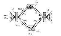
- FIG. 2 is a schematic diagram of a path of packet transmission capable of load balancing in the prior art.
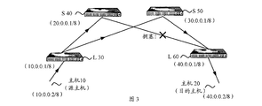
- FIG. 3 is a schematic structural diagram of a communication system to which a method for determining a transmission path provided by an embodiment of the present application is applied.
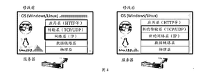
- FIG. 4 is a schematic diagram of a TCP/IP protocol stack before and after modification of the embodiment of the present application.
- FIG. 5 is a schematic flowchart of a method for determining a transmission path according to an embodiment of the present application.
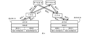
- FIG. 6 is a schematic diagram of path switching in the embodiment of the present application.
- FIG. 7 is a schematic block diagram of an apparatus for determining a transmission path according to an embodiment of the present application.
- FIG. 8 is a schematic structural diagram of an apparatus for determining a transmission path according to an embodiment of the present application.
- Clos network architecture is taken as an example for description, but the present application is not limited thereto, and the method for determining the transmission path proposed by the embodiment of the present application may be implemented in the scenario where all equal-cost paths exist.
- each of the underlying devices also known as a leaf device (English: leaf device), measures the leaf and other components in the entire network.
- Congestion-To-Leaf congestion information table
- Level 2 Clos refers to a Clos network with a 2-layer architecture.
- the lowest-level device is generally called Leaf, and the highest-level device is called Spine Device (Spine).
- Level 3 Clos refers to a Clos network with a 3-layer architecture.
- the bottom layer device is Leaf, the middle layer device is an aggregation device (English: aggregation device, Aggregation or Agg for short), and the highest layer device is called Spine (or Core).
- N-level Clos refers to Clos with an N-tier architecture.
- the Leaf is the lowest-level device under the Level 2 Clos architecture, the Level 3 Clos architecture, and even the N-level Clos architecture, typically a switch or router; Aggregation is a middle-tier device under the Level 3 Clos architecture; Spine is a Level 2 Clos Architecture, Level 3 Clos architecture, and even the highest level of equipment under the N-level Clos architecture, typically a switch or router.
- the flow includes a set of Transmission Control Protocol (English: transmission control protocol, referred to as "TCP”) / Internet Protocol (English: internet protocol, referred to as "IP”) that can be uniquely identified by a specific five-tuple (five key fields).
- TCP transmission control protocol
- IP internet protocol
- a user initiates a hypertext transport protocol (English: hypertext transport protocol (“HTTP”) access from a host with a source IP address of 202.100.1.2 to a web host with a destination IP address of 100.1.1.2.
- HTTP hypertext transport protocol
- the other two quintuple fields of the stream are source TCP port 20000, destination TCP port 8080, then 202.100.1.2+100.1.1.2+TCP+20000+8080 can be used to uniquely identify this stream transmitted in the network.
- the flow includes multiple packets. If the time difference between the two messages arrives greater than a configured value (for example, 500 microseconds), the next message can be used as the first one of the new short stream (English: flowlet). Packets; if the time difference between the first two packets is less than the configured value, the two packets belong to the same flowlet.
- a configured value for example, 500 microseconds
- the source leaf When the source leaf transmits the packet, it first detects the flowlet. If the time difference between the two packets arrives before the configured value (for example, 500 microseconds), the next packet is used as the first packet of the new flowlet. Otherwise, the two messages are considered to belong to the same flowlet.
- the configured value for example, 500 microseconds
- search for the port according to the following procedure: find the path congestion degree table (Congestion-To-Leaf table); find the destination leaf in the path congestion degree table according to the destination IP address of the packet; The leaf finds all the egress ports that can forward the packet; compares the congestion degree of all the outbound ports that can forward the packet, and selects the port with the lowest path congestion degree to forward the packet; if the path congestion degree table If the destination leaf corresponding to the destination IP address is not stored, or the congestion degree information of the destination leaf is not established at the initial time, one of the multiple outbound ports that can be forwarded is randomly selected; if the current packet belongs to the previous flowlet, Then look up the flowlet table, find the outbound port forwarding corresponding to the flowlet in the table.
- the path congestion degree table Congestion-To-Leaf table
- the establishment of the path congestion degree table is divided into two steps: forward detection and backward feedback.
- the forward detection process is mainly as follows: (1) When the probe packet is forwarded from the source leaf, the source leaf adds the leaf identifier to the probe packet, the identifier of the egress port used to forward the probe packet in the source leaf, and the indication. If the detection packet is forwarded from the source leaf to the Spine, the Spine determines the egress port for continuing to forward the probe packet. If the path corresponding to the egress port is found, The degree of congestion is higher than the congestion displayed in the probe packet received from the source leaf. Spine updates the field of the identifier used to record the congestion degree of the path in the probe packet. (3) When the probe packet reaches the destination leaf, the destination is The leaf records the degree of congestion displayed in the probe packet. (4) The destination leaf forwards the probe packet to the host.
- the backward feedback process is mainly: the host returns a TCP response packet for the probe packet to the source Leaf; The leaf searches for the source leaf corresponding to the TCP response, and writes the congestion information recorded in the previous forward detection process to the content of the packet, and performs the foregoing forwarding process. After the source leaf obtains the response packet, the path is congested. Information; the source Leaf uses the path congestion information just obtained to guide the next forwarding.
- Flow A and Flow B can be hashed to two or more transmission paths to achieve load balancing, thereby avoiding congestion of the transmission path.
- Gbps gigabits per second
- one stream strictly corresponds to one path.
- one stream is divided into multiple flowlets, and different flowlets are hashed to different paths, so one stream is transmitted on two or more paths at the same time.
- the flowlet is switched on two paths with different degrees of congestion, the flowlet is switched regardless of whether the current path is actually congested, which not only increases unnecessary switching, but may even cause packet transmission failure.
- Flow A is a flow
- flowlet 1 and flowlet 2 are respectively two flowlets in the flow A
- L0 and L1 are two leaves
- S0 and S1 are two Spines respectively.
- Flow A can take two paths from Leaf 0 to Leaf 1 switch, which are L0 ⁇ S0 ⁇ L1 and L0 ⁇ S1 ⁇ L1.
- the flowlet 1 in Flow A first reaches L0, assuming that the rate of flowlet 1 is 1G, and the degree of congestion of path L0 ⁇ S0 ⁇ L1 and path L0 ⁇ S1 ⁇ L1 is 0, assuming L0 selects L0 ⁇ S1 ⁇ L1 path Forward flowlet 1.
- the maximum flow rate that can be supported by the path L0 ⁇ S1 ⁇ L1 is 10G
- L0 finds that there is no congestion in the path of L0 ⁇ S1 ⁇ L1, so the flow rate is increased after the flowlet 2 is sent, and then the path L0 ⁇ S0 ⁇
- L0 comparison it is found that the degree of congestion of the path L0 ⁇ S1 ⁇ L1 is higher than the path L0 ⁇ S0 ⁇ L1, therefore,
- the L0 control flowlet 2 is forwarded through the path L0 ⁇ S0 ⁇ L1 with a congestion degree of zero.
- the defect of the current protocol stack mechanism may cause congestion mismatch. That is, the switching operation performed by Flow A on two paths with different degrees of congestion does not effectively guide Flow A to transmit, and is used to guide Flow A.
- the path switching is only a comparison of the degree of congestion between different paths, regardless of whether the specific path actually causes congestion for the flowlet 2.
- the switching of the transmission path is performed only when the current path does not cause congestion and the path switching is really necessary, and the problem of congestion mismatch is solved, and the basis of the path switching is whether the current path occurs. Congestion, rather than relying on the time difference between the arrival of messages before and after, thus avoiding the long tail effect.
- the embodiment of the present application solves the problem that the network device has insufficient entry specifications by storing the congestion information table in the host and performing the path selection policy by the host, and can be applied to the level 3 Clos or even the N-level Clos architecture.
- the embodiment of the present application also introduces a new indicator for evaluating the congestion degree of the path, and can more accurately evaluate the congestion degree of the path, thereby guiding the path switching more effectively.
- FIG. 3 is a schematic structural diagram of a communication system to which a method for determining a transmission path provided by an embodiment of the present application is applied.
- the Clos architecture there is a transmission path between each Leaf and all Spines.
- Host 10, Host 20, Leaf 30 (represented by L 30), Leaf 60 (represented by L 60), Spine 50 (represented by S 50), and Spine 40 (represented by S 40) are shown in FIG. .
- the Leaf here is, for example, a Leaf switch, and a host is connected under the Leaf switch.
- the host 10 After the host 10 sends the message, it is forwarded to the S 40 via the L 30. If the path of the S 40 to the L 60 is congested, the S 40 will mark the explicit congestion notification (English: explicit congestion notification, referred to as “ECN”). ), indicating that the stream to which the message belongs has experienced congestion on the device. After the packet is forwarded to the host 20 through the L60, the host 20 will return the explicit congestion notification echo (ECN-Echo) to the host 10 after seeing the packet with the CE flag. After receiving the ECN-Echo, Host 10 senses that congestion occurs on the transmission path, lowers its transmission rate, and sends a congestion window reduction ("CWR") message to the destination. Host 20, to inform Host 20 that it has performed the slowdown operation.
- CWR congestion window reduction
- TLB transport layer aware load balancing
- the host when the transmission path is congested, the host may perform the path reselection according to the path congestion information table. That is, the method for determining the transmission path in the embodiment of the present application may be implemented in the operating system of the host. There is no need to make any modifications to network devices such as switches, routers, etc.
- the operating system of the host may be, for example, a network processing portion of a Windows/Linux operating system kernel code or the like.
- the embodiment of the present application The method can be applied to, but not limited to, a socket module communication of a TCP/IP protocol stack, an application programming interface ("API") interface, and the like.
- the method of the embodiment of the present application can also be applied to a virtual machine system, such as a cloud service operating system of VMware, Xen virtual machine, Openstack, and the like, and a virtual machine monitor function module part of the virtualization operating system.
- a virtual machine system such as a cloud service operating system of VMware, Xen virtual machine, Openst
- FIG. 4 is a schematic diagram of a TCP/IP protocol stack before and after modification according to an embodiment of the present application.
- the left figure is a schematic diagram of the TCP/IP protocol stack before modification
- the right figure is a schematic diagram of the modified TCP/IP protocol stack.
- the method for determining the transmission path in the embodiment of the present application may be implemented after the modification of the transport layer and the network layer in the operating system of the host.
- the congestion information table is stored in the host, and can be flexibly applied to the level 3 Clos architecture or even the N-level Clos architecture without being restricted by the specification of the network device.
- FIG. 5 is a schematic flowchart of a method 500 for determining a transmission path according to an embodiment of the present application. The method is described by the host as an example. As shown in FIG. 5, the method 500 includes:
- S510 The host determines that congestion occurs on the current path corresponding to the flow to which the packet to be transmitted belongs.
- each entry in the flow-path table includes a correspondence between an identifier of the flow and a forwarding path selected by the host for the flow.
- the host When the host receives the packet to be transmitted, it determines the flow to which the packet to be transmitted belongs, and then searches the flow-path table to obtain a forwarding path corresponding to the flow, where the obtained path is the to-be-transmitted The current path corresponding to the stream to which the packet belongs.
- S520 The host determines, according to the path congestion information table, the target path for the to-be-transmitted packet, and adds the information of the target path to the to-be-transmitted packet, so that the to-be-transmitted packet is transmitted according to the target path, where The target path has less congestion than the current path.
- a forwarding path table is further disposed on the host.
- the forwarding path table records all paths of the leaf connected by the host to any other leaf in the network.
- the forwarding path table on Host 10 includes all paths from L30 to L60: L30 ⁇ S40 ⁇ L60; L30 ⁇ S50 ⁇ L60.
- the host sends the to-be-transmitted packet according to the target path.
- Each entry of the path congestion information table includes an identifier of a transmission path and congestion information corresponding to the transmission path, where the congestion information is used to indicate a congestion degree of the transmission path.
- the path congestion information table is stored in the host, the path congestion information table records the identifiers of the plurality of transmission paths, and the congestion information corresponding to each of the multiple transmission paths, wherein the identifier of the transmission path can be recorded as:
- the ground 40.0.0.2 the switch identifier L30, L40, L60, indicates that the address of the destination (for example, another host) to which the transmission path arrives is 40.0.0.2, and the passing devices are L30, L40, and L60 in order.
- the congestion information of one transmission path may include at least one of the following: an average number of ECNs of the transmission path, a round trip time RTT of the transmission path, an identifier indicating whether the transmission path is faulty, And the number of streams that exist simultaneously on the pass path.
- the path may be determined according to the path congestion information table, and the target path is added to the to-be-transmitted packet. Transmitting the packet, so that the to-be-transmitted packet is transmitted through the target path, where the congestion degree of the target path is smaller than the congestion degree of the current path.
- the host determines the target path for the to-be-transmitted message only when it is determined that congestion is actually occurring on the current path corresponding to the to-be-transmitted message. And sending the to-be-transmitted message through the determined target path.
- the message to be transmitted becomes the first message of a new flowlet of the stream to which the message to be transmitted belongs.
- the current path here is the path that the to-be-transmitted packet is to be used, that is, the path taken by the previous packet in the stream to which the to-be-transmitted packet belongs. If the path of the previous packet of the packet to be transmitted does not cause congestion, the host will continue to transmit subsequent packets on the path. In this case, the current path of the packet to be transmitted is the previous one. The path taken by the message. If the path of the previous packet is congested, the host determines a new path (that is, the above-mentioned target path) for the flow to which the packet to be transmitted belongs, and the to-be-transmitted packet is transmitted on the target path. Instead of transmitting on the current path, the message to be transmitted becomes the first message of a new flowlet of the stream to which the message to be transmitted belongs.
- whether a new short stream is generated for one stream is not determined according to the difference in arrival time between the two messages, but is determined according to whether the current transmission path is congested. If congestion occurs on the current path corresponding to the flow to which the packet to be transmitted belongs, the stream is sliced to generate a new short stream. That is, the transmission path of the packet is re-determined only if the current path corresponding to the flow to which the packet to be transmitted belongs is congested.
- the first path of the flow transmission process may be referred to as routing, and the operation of switching the new short stream in the flow to a path different from the previous short stream may be referred to as rerouting (Rerouting). ).
- the host may determine whether the current path is congested by whether the flow described in the to-be-transmitted message is marked with an explicit congestion notification ECN, an RTT of the transmission path, or an identifier for indicating whether the transmission path is faulty. That is, the host determines that the stream to which the packet to be transmitted belongs is set with the ECN flag when the current path is transmitted, or the round-trip time RTT corresponding to the current path is greater than the time threshold, or the current path is faulty, indicating that the current path is congested, and the host is The to-be-transmitted message re-determines the target path.
- the host finds that the stream to which the packet to be transmitted belongs is set with the ECN flag when transmitting the current path, it indicates that congestion occurs on the current path; or a time threshold can be set, if the network device finds the slave report The time between the receipt of the response message for the message, that is, the round trip time RTT suddenly becomes longer than the preset time threshold, indicating that congestion occurs on the current path; or the current path fails, then Congestion will occur when transmission is inevitable on the current path.
- the host can query the path congestion information table, and determine the target path for the to-be-transmitted message through the congestion information table.
- the congestion degree of the target path is lower than the current path, so that the to-be-transmitted packet can be switched to a better path.
- the number of streams that exist simultaneously on the path is smaller than the number of streams that exist simultaneously on the current path, and the target path does not fail.
- the embodiment of the present application includes an average ECN number, a round trip time RTT, an identifier for indicating whether the path is faulty, and a path on the path, as compared with the prior art, which only relies on the utilization of the outbound port for a period of time.
- Congestion information of parameters such as the number of transmitted packets simultaneously characterizes the congestion degree of the transmission path, and can more accurately evaluate the congestion degree of the path, thereby guiding the path switching more effectively.
- the method further includes: the host obtains congestion information corresponding to each of the at least one transmission path; and the host transmits according to the at least one The congestion information corresponding to each transmission path in the path is used to establish or update the path congestion information table.
- the host obtains each path that can be used for packet transmission, and congestion information of each path, thereby establishing a path congestion information table, and the host may send a probe packet on each of the at least one transmission path.
- Information generating a path congestion information table.
- the host may continuously update the path information table according to a certain period.
- the host can obtain the congestion information of each path by sending the probe packet, and the probe packet is transmitted on the specified path through the source route, the X path, or the like to obtain the congestion of each path.
- Information establish a path congestion information table.
- the source route or XPath here is a routing policy based on source address routing, which can selectively send data packets to different destination addresses according to multiple different addresses.
- the source host may sequentially send probe packets on all existing transmission paths according to the forward detection method described above. If congestion occurs at a certain device during the transmission of the probe packet, the device marks the ECN on the probe packet. When the probe packet is transmitted to the destination host, the destination device learns the path. Congestion occurs. When a response packet to the probe packet is returned to the host, the message that the path is congested is carried in the response packet, so that the source host knows that congestion occurs on the path.
- the source host obtains the RTT in the congestion information of each path in the congestion information table
- the time at which the probe packet is sent and the time when the response packet is received may be recorded, and the duration between the two moments is the RTT.
- the longer the RTT the higher the congestion of the path.
- the path congestion information table may be, for example, shown in Table 1.
- the information recorded in each entry in Table 1 includes, in addition to a path identifier (English: identifier, "ID”) and a destination device (Dest) (ie, a destination Host). It also includes congestion information: average number of ECNs, round trip time RTT, fault link (English: failure), and the number of simultaneous streams on the transmission path.
- Path A, Path B, Path C, and Path D are used for transport stream 1 (flow 1)
- Path E and Path F are used for transporting flow 2
- Path G and Path H are used for transporting flow 3.
- the quintuple information of the flow flow 1, flow 2, and flow 3 can be stored in the flow table shown in Table 2, and the table 2 also includes at least one transmission path that each stream can use.
- the host may update the path congestion information table, for example, by using an active probe to initiate periodic active detection, and record the average number of ECNs of each transmission path, the RTT, and the identifier indicating whether the transmission path is faulty. Save to the path congestion information table of the host. The host can also classify the path based on this information to guide the path switch.
- the end-to-end RTT is not necessarily the bad path (English: bad path), or it may be caused by the host OS processing delay, but the small RTT must be a good path (English: good path); the average of the stream
- the small number of ECNs is not necessarily a good path. It may be caused by a critical threshold or insufficient sampling of the switch, but the average number of ECNs is large. It is a bad path.
- the bad path can refer to a path with a high degree of congestion, which is mainly based on the average number of ECNs of each path, RTT, etc., for example, the greater the average number of ECNs on a path, the worse the path is.
- the packets are all congested, and obviously this path is a bad path compared to a path with an average ECN of 0.1. For another example, if a path fails, then this path is definitely a bad path and needs to be avoided.
- the host uses the transmission path corresponding to the identifier from the path congestion information table. delete.
- the path and the related information of the path may be deleted from the path congestion information table in time, and the path congestion information table may perform the update operation in real time.
- the path selection can be performed in the path without failure.
- the congestion of the transmission path is determined, and when the path congestion occurs, a new path is determined for the to-be-transmitted message according to the path congestion information table, so that the problem of congestion of the transmission path can be effectively solved.
- the transmission path is switched, the congestion mismatch is avoided, and the path switching is based on whether congestion occurs on the current path. Rather than relying on the time difference between the arrival of messages before and after, the long tail effect is avoided.
- the decision of the entire path is performed by the host, and the congestion information table is stored in the host, thereby solving the problem that the specification of the network device is insufficient, and can be applied to the level 3 Clos or even the N-level Clos architecture.
- the embodiment of the present application also introduces a new indicator for evaluating the congestion degree of the path, and can more accurately evaluate the congestion degree of the path, thereby guiding the path switching more effectively.
- the host determines, according to the path congestion information table, a target path for the to-be-transmitted packet, where: the to-be-transmitted packet and other packets to be transmitted on the current path, if And the host determines the target path for the to-be-transmitted message according to the path congestion information table, so that the to-be-transmitted message is transmitted according to the target path.
- path 1 For example, suppose that the current path of message 1, message 2, and message 3 to be transmitted and belonging to different flows is path 1, that is, three messages are intended to be transmitted on path 1, assuming that path 1 occurs at this time. For congestion, you need to re-select the destination path for the flow to which the message 1 belongs, the flow 2 to which the message 2 belongs, and the flow 3 to which the message 3 belongs. However, when the host selects a new transmission path, it is not convective. The stream 2 and the stream 3 both switch the transmission path, but perform path switching on one or two of the three streams. For example, a preset probability of 1/3 indicates that only one flow is switched in one of the three flows.
- the server of flow 1 performs path switching on flow 1, and the flow congestion information table is the message 1 in flow 1.
- the target path is determined as a new transmission path, and no path switching is performed for stream 2 and stream 3, so that packet 2 in stream 2 and message 3 in stream 3 are still transmitted on the current path.
- the advantage of this is that the probability of re-congestion after switching is reduced. If only path 1 and path 2 exist, and three streams are switched at the same time, stream 1, stream 2 and stream 3 will all be switched to path 2 for transmission. There is still a possibility of collision between message 1, message 2 and message 3.
- This embodiment can appropriately avoid the situation that multiple streams are simultaneously switched to another same path and cause congestion of another path, effectively balancing the load to different transmission paths, thereby reducing the probability of re-congestion after handover. , improve the success rate of message transmission.
- determining which stream in stream 1, stream 2, and stream 3 is to be switched it may be randomly selected; or a random number may be generated to see if it can be divisible by 3, if it can be divisible by 3, the path is switched; otherwise The path is not switched, and one or two streams with the highest flow rate may be selected for path switching, etc., which are not limited in this embodiment.
- the handover is unsuccessful, you can wait for a short delay (English: short delay) before switching again to improve the success rate of the handover again. For example, if the host does not successfully perform the path switching on the flow 1 to which the packet 1 belongs, it needs to wait for a fixed duration, for example, 100 ms, and then perform the path switching operation on the flow 1.
- a short delay English: short delay
- the host determines the target path for the to-be-transmitted packet according to the path congestion information table, and may further include: if the flow rate of the flow corresponding to the to-be-transmitted packet is greater than a preset threshold, the host is congested according to the path.
- the information table determines a target path for the to-be-transmitted message.
- the object selected by the host may be a flow whose flow rate exceeds a certain size, and when the flow rate of the flow exceeds a certain threshold, the host performs a path switching operation on the flow.
- the host senses the flow rate of the flow, for example, the TCP window rate calculation, and the RTT is calculated when there is no packet loss, and the packet loss rate is based on the packet loss rate. RTT is calculated according to the TCP throughput formula.
- the path switching operation is performed on the flow to which the packet to be transmitted belongs only when the flow rate of the flow exceeds the preset threshold. Otherwise, the path switching is not performed because it is not necessary to slice the flow with a small flow rate. This avoids unnecessary path switching.
- the method may further include: determining, by the host, a time difference between the RTT of the target path and the RTT of the current path; and after the host is equal to the time difference of the time difference, sending, by the host, the to-be-transmitted message.
- Flow A is divided into flowlet 1, flowlet 2, and flowlet 3, flowlet 1 and flowlet 2 are transmitted on path 1, and flowlet 3 is switched to path 2, if the congestion degree of path 2 is less than path 1.
- the order of the messages in the Flow A changes from the original flowlet 1 ⁇ flowlet 2 ⁇ flowlet 3 to the flowlet 3 ⁇ flowlet 1 ⁇ flowlet 2, then the occurrence occurs. Out of order.
- the host determines that the current path corresponding to the flow to which the packet to be transmitted belongs is congested, and after determining a new path, that is, the target path, the host can determine the RTT of the target path and the current path. The time difference between the RTTs, so that the host sends the to-be-transmitted message after the time difference of the time difference. This can avoid message out of order caused by path switching.
- FIG. 6 is a schematic diagram of path switching according to a method according to an embodiment of the present application, including a sender 10, a receiver 20, a Leaf 30, a Spine 40, a Spine 50, and a Leaf 60.
- a sender 10 a receiver 20
- a Leaf 30 a Spine 40
- a Spine 50 a Spine 50
- a Leaf 60 a Leaf 60.
- the transport layer of the host of the transmitting end 10 can implement the transport layer-aware load balancing TLB, and the transport layer of the host of the receiving end 20 can also implement the transport layer-aware load balancing TLB.
- the method for determining the transmission path specifically includes:
- the first routing operation (Route): the host searches for the path congestion information table for the new flow, and randomly selects the transmission path in the path other than the bad path, and the bad path can be performed by the host according to the foregoing method, that is, according to the average number of ECNs, Information such as RTT is determined. As shown in Figure 6, the host first selects Path 1 for flowlet 1 in Flow A to send packets.
- Path congestion occurs on Path 1, and the host determines whether to perform re-routing operation for Flow A.
- the path congestion of Path 1 may be: the host 10 determines that the Flow A is set to be ECN when the Flow A is transmitted on the Path 1, the average number of ECNs of the Path 1 is greater than a preset value, and the RTT of the Path 1 exceeds a preset threshold, or A link failure occurred on Path 1.
- the host may determine whether to perform the rerouting operation for the flowlet 2 according to the flow rate of the flow A. When the flow rate is greater than the preset threshold, the flow A is rerouted, otherwise the skip selects whether the next flow meets the requirement; the host may also pre-set according to the requirement. The probability value is determined to determine whether to perform a rerouting operation for Flow A.
- the target path is determined according to the path congestion information table for transmission as flowlet 2 in Flow A.
- the host searches the path congestion information table, selects the target path, for example, Path 2 here, and carries the information of Path 2 in the flowlet 2, so that the flowlet 2 transmits according to Path 2.
- Path 2 satisfies at least one of the following conditions: the average ECN number of Path 2 is smaller than the average ECN number of Path 1, the RTT of Path 2 is shorter than the RTT of Path 1, and the number of simultaneously transmitted packets on Path 2 is smaller than that of Path 1. The number of transmitted packets.
- the host determines the time difference between the RTT of Path 1 and the RTT of Path 2.
- the time difference between the RTT of the host computing host Path 1 and the RTT of the Path 2 is, for example, 100 us.
- the host determines a new path for the to-be-transmitted message according to the path congestion information table when the path is congested, and effectively solves the problem of congestion of the transmission path.
- the size of the sequence numbers of the foregoing processes does not mean the order of execution sequence, and the order of execution of each process should be determined by its function and internal logic, and should not be applied to the embodiment of the present application.
- the implementation process constitutes any limitation.
- FIG. 7 illustrates an apparatus 700 for determining a transmission path in accordance with an embodiment of the present application.
- the apparatus 700 includes a determining unit 710 and a transmitting unit 720. among them:
- the determining unit 710 is configured to: determine that congestion occurs on the current path corresponding to the flow to which the to-be-transmitted message belongs; determine a target path for the to-be-transmitted message according to the path congestion information table, and add the information of the target path to the Transmitting a message to transmit the to-be-transmitted message through the target path, where a congestion degree of the target path is smaller than a congestion degree of the current path, and each path congestion information table is The entry includes a transmission path and congestion information corresponding to the transmission path, where the congestion information is used to indicate a congestion degree of the transmission path;
- the sending unit 720 is configured to: send the to-be-transmitted message according to the target path determined by the determining unit.
- the apparatus for determining a transmission path in the embodiment of the present application can effectively solve the congestion of the transmission path by determining whether the transmission path is congested and determining a new path for the to-be-transmitted message according to the path congestion information table when the path is congested. problem.
- the embodiment of the present application only performs the congestion of the current path and the path switching is really necessary, the transmission path is switched, and the congestion mismatch is avoided, and the congestion degree of the switched path is smaller than the The current path avoids the long tail effect.
- the decision of the entire path does not need to be performed by a network device such as a switch or a router, but is implemented by other devices such as a host, and information such as a congestion information table may also be saved in the host, thereby solving the table.
- a network device such as a switch or a router
- information such as a congestion information table may also be saved in the host, thereby solving the table.
- the problem of limited item specifications can be applied to the Level 3 Clos or even the N-level Clos architecture.
- the embodiment of the present application also introduces a new evaluation index for evaluating the degree of congestion of the path, such as the average number of ECNs, the round trip time RTT, the identifier for indicating whether the path is faulty, and the number of streams simultaneously present on the path. Parameters, which can more accurately evaluate the congestion degree of the path and guide the path switching more effectively.
- the determining unit 710 is specifically configured to: when the flow is determined to be transmitted on the current path, the marked explicit congestion notification ECN, or the round-trip time RTT corresponding to the current path is greater than a time threshold, or The current path has failed.
- the congestion information includes at least one of the following: an average number of ECNs of the transmission path, a round trip time RTT of the transmission path, an identifier indicating whether the transmission path is faulty, and the The number of streams that exist simultaneously on the transmission path.
- the flow rate of the flow corresponding to the to-be-transmitted packet is greater than a preset threshold, determine a target path for the to-be-transmitted packet according to the path congestion information table.
- the determining unit 710 is specifically configured to: if the to-be-transmitted packet is selected by using a preset probability, in the to-be-transmitted packet and other packets to be transmitted on the current path, And determining, according to the path congestion information table, the target path for the to-be-transmitted message, so that the to-be-transmitted message is transmitted according to the target path.
- the determining unit 710 is further configured to: determine a time difference between an RTT of the target path and an RTT of the current path; the sending unit is further configured to: after the duration of the time difference elapses, send The message to be transmitted.
- the device further includes a receiving unit, where the sending unit 720 is further configured to: send a probe message on each of the at least one transmission path; the receiving unit is configured to receive, for the Determining, by the determining unit, the congestion information corresponding to each transmission path in the at least one transmission path according to the response message; the determining unit is further configured to: The congestion information corresponding to each of the at least one transmission path generates the path congestion information table.
- the determining unit is further configured to: if the obtained congestion information of a transmission path includes an identifier indicating that the transmission path is faulty, the entry corresponding to the transmission path is from the path congestion information table. delete.
- FIG. 8 shows a structure of an apparatus for determining a transmission path provided by an embodiment of the present application, a processor 810, a transceiver 820, and a memory 830, wherein the processor 810, the transceiver 820, and the memory 830 communicate with each other through an internal connection path. Communication.
- the memory 830 is for storing instructions, and the processor 810 is configured to execute instructions stored by the memory 830 to control the transceiver 820 to receive signals or send signals. among them:
- the processor 810 is configured to: determine, according to the path congestion information table, a target path for the to-be-transmitted message, and add the information of the target path to the to-be-transmitted packet, so that the to-be-transmitted packet passes
- the target path is transmitted, wherein the congestion degree of the target path is smaller than the congestion degree of the current path, and each entry of the path congestion information table includes a transmission path and congestion information corresponding to the transmission path.
- the congestion information is used to indicate a degree of congestion of the transmission path;
- the transceiver 820 is configured to: send the to-be-transmitted message according to the target path determined by the determining unit.
- the apparatus for determining a transmission path in the embodiment of the present application can effectively solve the congestion of the transmission path by determining whether the transmission path is congested and determining a new path for the to-be-transmitted message according to the path congestion information table when the path is congested. problem.
- the processor 810 is specifically configured to: when the flow is transmitted on the current path, the marked explicit congestion notification ECN, or the round-trip time RTT corresponding to the current path is greater than a time threshold, or The current path has failed.
- the congestion information includes at least one of the following: an average number of ECNs of the transmission path, a round trip time RTT of the transmission path, an identifier indicating whether the transmission path is faulty, and the The number of streams that exist simultaneously on the transmission path.
- the flow rate of the flow corresponding to the to-be-transmitted packet is greater than a preset threshold, determine a target path for the to-be-transmitted packet according to the path congestion information table.
- the processor 810 is specifically configured to: if the to-be-transmitted packet is selected by using a predetermined probability, in the to-be-transmitted packet and other packets to be transmitted on the current path, And determining, according to the path congestion information table, the target path for the to-be-transmitted message, so that the to-be-transmitted message is transmitted according to the target path.
- the processor 810 is further configured to: determine a time difference between an RTT of the target path and an RTT of the current path; the transceiver 820 is further configured to: after the duration of the time difference elapses, Sending the to-be-transmitted message.
- the transceiver 820 is further configured to: send a probe packet on each of the at least one transmission path; the transceiver 820 is further configured to receive a response packet for the probe packet.
- the processor 810 is further configured to: determine, according to the response message, the congestion information corresponding to each of the at least one transmission path; the processor 810 is further configured to: according to the at least one transmission path And generating, by the congestion information corresponding to each transmission path, the path congestion information table.
- the determining unit is further configured to: if the obtained congestion information of a transmission path includes an identifier indicating that the transmission path is faulty, the entry corresponding to the transmission path is from the path congestion information table. delete.
- the processor 810 may be a central processing unit (“CPU"), and the processor 810 may also be other general-purpose processors and digital signal processors (English: digital Signal processor (referred to as "DSP”), application-specific integrated circuit (ASIC), ready-to-use programmable gate array (English: field programmable gate qrray, "FPGA”) or other programmable logic Devices, discrete gates or transistor logic devices, discrete hardware components, etc.
- DSP digital Signal processor
- ASIC application-specific integrated circuit
- FPGA ready-to-use programmable gate array
- the general purpose processor may be a microprocessor or the processor or any conventional processor or the like.
- the memory 830 can include read only memory and random access memory and provides instructions and data to the processor 810. A portion of the memory 830 may also include a non-volatile random access memory. For example, the memory 830 can also store information of the device type.
- a person skilled in the art can clearly understand that for the convenience and brevity of the description, the specific working process of the system, the device and the unit described above can refer to the corresponding process in the foregoing method embodiment, and details are not described herein again.
- each step of the foregoing method may be completed by an integrated logic circuit of hardware in the processor 810 or an instruction in a form of software.
- the steps of the positioning method disclosed in the embodiments of the present application may be directly embodied as hard.
- the execution of the processor is completed or performed by a combination of hardware and software modules in the processor 810.
- the software module can be located in a conventional storage medium such as random access memory, flash memory, read only memory, programmable read only memory or electrically erasable programmable memory, registers, and the like.
- the storage medium is located in memory 830, and processor 810 reads the information in memory 830 and, in conjunction with its hardware, performs the steps of the above method. To avoid repetition, it will not be described in detail here.
- the disclosed systems, devices, and methods may be implemented in other manners.
- the device embodiments described above are merely illustrative.
- the division of the unit is only a logical function division.
- there may be another division manner for example, multiple units or components may be combined or Can be integrated into another system, or some features can be ignored or not executed.
- the mutual coupling or direct coupling or communication connection shown or discussed may be an indirect coupling or communication connection through some interface, device or unit, and may be in an electrical, mechanical or other form.
- the units described as separate components may or may not be physically separated, and the components displayed as units may or may not be physical units, that is, may be located in one place, or may be distributed to multiple network units. Some or all of the units may be selected according to actual needs to achieve the purpose of the solution of the embodiment.
- each functional unit in each embodiment of the present application may be integrated into one processing unit, or each unit may exist physically separately, or two or more units may be integrated into one unit.
- the functions may be stored in a computer readable storage medium if implemented in the form of a software functional unit and sold or used as a standalone product. Based on such understanding, the technical solution of the embodiments of the present application, or the part contributing to the prior art or the part of the technical solution, may be embodied in the form of a software product stored in a storage medium. A number of instructions are included to cause a computer device (which may be a personal computer, host, or network device, etc.) to perform all or part of the steps of the methods described in various embodiments of the present application.
- a computer device which may be a personal computer, host, or network device, etc.
- the foregoing storage medium includes: a U disk, a mobile hard disk, a read-only memory (ROM: ROM), a random access memory (English: random access memory, referred to as "RAM”), a disk or a disk. And other media that can store program code.
- ROM read-only memory
- RAM random access memory
Landscapes
- Engineering & Computer Science (AREA)
- Computer Networks & Wireless Communication (AREA)
- Signal Processing (AREA)
- Data Exchanges In Wide-Area Networks (AREA)
Abstract
本申请实施例提供了一种确定传输路径的方法和装置,该方法包括:确定待传输报文所属的流对应的当前路径上发生拥塞;根据路径拥塞信息表,为所述待传输报文确定目标路径,并将所述目标路径的信息添加在所述待传输报文中,以使得所述待传输报文根据所述目标路径进行传输,其中,所述目标路径的拥塞程度比所述当前路径的拥塞程度小,所述路径拥塞信息表的每个表项包括一条传输路径以及所述传输路径对应的拥塞信息,所述拥塞信息用于表示所述传输路径的拥塞程度。从而有效地解决传输路径拥塞的问题。
Description
本申请要求于2016年12月27日提交中国专利局、申请号为201611229376.5、发明名称为“确定传输路径的方法和装置”的中国专利申请的优先权,其全部内容通过引用结合在本申请中。
本申请实施例涉及通信领域,并且更具体地,涉及一种确定传输路径的方法和装置。
互联网数据正在以爆炸性的方式增长,中国的新浪微博注册用户数量已经破3亿,腾讯的即时通讯工具活跃用户达到7.1亿,Facebook全球用户数量则正逼近10亿,仅次于中国和印度的人口数字。仅社交网络这一项所产生的数据就已经非常惊人。据国际数据公司IDC发布的报告《Digital Universe Study 2011》显示,全球信息总量每过两年就会增长一倍。仅在2011年,全球被创建和被复制的数据总量为1.8ZB(即1.8万亿GB)。相较2010年同期上涨超过1ZB,到2020年这一数值将增长到35ZB。大数据的出现正迫使企业不断提升自身以数据中心为平台的数据处理能力。
Google、Microsoft及Facebook等巨头在数据中心的网络领域走在业界最前沿,这些业界引领者的多年研究及实践表明,基于克劳斯(英文:Clos)架构的数据中心网络扩展性佳,等价路径多,因此正得到越来越广泛的部署。
Clos数据中心网络架构尽管有等价路径多的优势,但是在传统的负载均衡(英文:load balancing,简称“LB”)机制下却容易出现严重的路径拥塞。图1是一个典型的数据中心3层Clos网络构架的示意图,每层设备例如可以为交换机、路由器等网络设备,其中,底层设备为架顶设备,或称为叶子设备(英文:leaf device,简称“Leaf”);中间层设备为汇集设备(英文:aggregation device,简称“Agg”);顶层设备为核心设备(英文:core device,简称Core)。如图1所示,该Clos网络中有四条流(Flow)即Flow A、Flow B、Flow C和Flow D,分别从不同的源设备转发到不同的目的设备。尽管网络中存在不止四条路径可以完成这四条流的转发,但是由于传统的负载均衡机制的缺陷,会导致转发路径出现重叠。如图1所示,Flow A与Flow B在中间层设备Agg 0处发生了本地冲突(英文:local collision),即,Flow A与Flow B本可以通过走不同路径(例如分别通过路径Agg 0→Core 0和路径Agg 0→Core 1)进行传输,但由于某些控制机制的缺陷等导致Flow A与Flow B都使用路径Agg 0→Core 0进行传输,假设Flow A与Flow B的流速均为6G,Agg 0最大能满足的流速为10G,当Flow A与Flow B在Agg 0处交汇时,由于6G×2=12G超过了10G,导致了Flow A与Flow B在Agg 0处发生冲突。图1中的Flow C与Flow D在Core 2处发生下游冲突(英文:downstream collision),即,由于Core 2到下游目的设备之间只存在一条路径(即Core 2→Agg 3),从而导致Flow C与Flow D必然会在Core 2处发生冲突。因此,如何通过优化负载均衡机制避免网络中出现局部拥塞导致丢包已成为当下业内的焦点。
发明内容
本申请实施例提供一种确定传输路径的方法和装置,能够有效地解决传输路径拥塞的问题。
第一方面,提供了一种确定传输路径的方法,该方法包括:
确定待传输报文所属的流对应的当前路径上发生拥塞;
根据路径拥塞信息表,为所述待传输报文确定目标路径,并将所述目标路径的信息添加在所述待传输报文中,以使得所述待传输报文根据所述目标路径进行传输,其中,所述目标路径的拥塞程度比所述当前路径的拥塞程度小,所述路径拥塞信息表的每个表项包括一条传输路径以及所述传输路径对应的拥塞信息,所述拥塞信息用于表示所述传输路径的拥塞程度;
根据所述目标路径,发送所述待传输报文。
因此,本申请实施例中,通过确定传输路径发生拥塞,并在发生路径拥塞时根据路径拥塞信息表为待传输报文确定新的路径,能够有效地解决传输路径拥塞的问题。
由于本申请实施例只有在当前路径确实发生拥塞、确实有必要进行路径切换时,才会进行传输路径的切换,避免了拥塞不匹配等问题,且切换后的路径的拥塞程度小于该当前路径,避免了长尾效应。
另外,本申请实施例中,交换机、路由器等网络设备上可以不做任何修改,整个路径的决策可以由其他装置例如主机来执行,拥塞信息表可以保存在主机中,从而解决了表项规格受限的问题,能够适用于3级Clos甚至N级Clos架构中。其中,N大于3。
可选地,在第一方面的一种实现方式中,所述确定待传输报文所属的流对应的当前路径上发生拥塞,包括:确定所述流在所述当前路径上传输时被标记显式拥塞通知ECN,或者所述当前路径对应的往返时间RTT大于时间阈值,或者所述当前路径发生故障
可选地,在第一方面的一种实现方式中,所述拥塞信息包括以下信息中的至少一种:所述传输路径的平均ECN次数、所述传输路径的RTT、用于表示所述传输路径是否故障的标识、以及所述传输路径上同时存在的流的个数。
相比于现有技术中仅仅依靠一段时间内出端口的利用率来表示路径的拥塞程度,本申请实施例通过包括平均ECN次数、往返时间RTT、用于表示路径是否故障的标识、以及路径上同时存在的流的个数等参数的拥塞信息来表征传输路径的拥塞程度,能够更加准确的对路径的拥塞程度进行评价,从而更有效地指导路径切换。
可选地,在第一方面的一种实现方式中,所述根据路径拥塞信息表,为所述待传输报文确定目标路径之前,所述方法还包括:确定所述待传输报文所属的流的流速是否大于预设阈值;若所述流的流速大于所述预设阈值,执行所述根据所述路径拥塞信息表,为所述待传输报文确定目标路径的步骤。
由于只在流速超过预设的阈值时才对该待传输报文进行路径切换操作,从而避免了不必要的切换,例如对较小的流进行切片就完全没有必要。
可选地,在第一方面的一种实现方式中,所述根据路径拥塞信息表,为所述待传输报文确定目标路径,包括:在所述待传输报文和所述当前路径上待传输的其他报文中,若所述待传输报文以预设概率被选择到,则根据所述路径拥塞信息表,为所述待传输报文确定所述目标路径,以使得所述待传输报文根据所述目标路径进行传输。
这样,当前路径发生拥塞时,在该路径上将要传输的至少一个流中,不是所有流一起进行路径切换,而是根据预设概率选择一部分流进行路径切换,从而降低了切换后再次发生拥塞的概率,提高了报文传输的成功率。
可选地,在第一方面的一种实现方式中,所述方法还包括:确定所述目标路径的RTT与所述当前路径的RTT之间的时间差;在经过所述时间差的时长后,发送所述待传输报文。
为了避免乱序的发生,主机确定待传输报文对应的当前路径发生拥塞而为该报文所属的流确定了新的路径即目标路径后,主机可以确定该目标路径的RTT与该当前路径的RTT之间的时间差,从而主机在等于该时间差的时长后,再发送该待传输报文。这样可以避免路径切换导致的报文乱序。例如对报文1所述的流进行路径切换没有成功,则需要等待固定时长例如100ms后,再对报文1所述的流执行路径切换操作。
可选地,在第一方面的一种实现方式中,所述在根据路径拥塞信息表,为所述待传输报文确定目标路径之前,所述方法还包括:在至少一条传输路径中的每条传输路径上发送探测报文;接收针对所述探测报文的响应报文;根据所述响应报文,确定至少一条传输路径中每条传输路径对应的所述拥塞信息;根据所述至少一条传输路径中每条传输路径对应的所述拥塞信息,生成所述路径拥塞信息表。
进一步地,主机还可以周期性地或者实时地,对该路径拥塞信息表进行更新,对路径拥塞信息表的更新例如可以通过有源探测器(英文:active probe)发起定期主动探测,记录平均ECN次数、RTT等等信息并保存到路径拥塞信息表中,以主机为例,保存目的地可以为主机本地例如主机内存或硬盘中。同时还可以依据平均ECN次数、RTT等信息为路径划分等级,以对路径切换进行指导。
可选地,在第一方面的一种实现方式中,所述方法还包括:若获取的一条传输路径的拥塞信息中包括表示所述传输路径发生故障的标识,将所述传输路径对应的表项从所述路径拥塞信息表中删除。
也就是说,主机在获取到哪条路径故障后,可以及时将该路径以及该路径的相关信息从该路径拥塞信息表中删除,路径拥塞信息表可以实时地进行该更新操作。在后续的路径选择过程中,就可以在没有故障的路径中进行路径选择。
第二方面,提供了一种确定传输路径的装置,该装置可以用于执行前述第一方面及各种实现方式中所述的确定传输路径的方法中的各个过程。该装置包括确定单元和发送单元,其中,确定单元,用于确定待传输报文所属的流对应的当前路径上发生拥塞;所述确定单元还用于,根据路径拥塞信息表,为所述待传输报文确定目标路径,并将所述目标路径的信息添加在所述待传输报文中,以使得所述待传输报文通过所述目标路径进行传输,其中,所述目标路径的拥塞程度比所述当前路径的拥塞程度小,所述路径拥塞信息表的每个表项包括一条传输路径以及所述传输路径对应的拥塞信息,所述拥塞信息用于表示所述传输路径的拥塞程度;
发送单元,用于根据所述确定单元确定的目标路径,发送所述待传输报文。
第三方面,提供了一种确定传输路径的装置,该装置包括收发器、处理器和存储器。所述存储器存储了程序,所述处理器执行所述程序,以用于执行前述第一方面及各种实现方式中所述的确定传输路径的方法中的各个过程。其中,所述处理器具体用于:确定
待传输报文所属的流对应的当前路径上发生拥塞;根据路径拥塞信息表,为所述待传输报文确定目标路径,并将所述目标路径的信息添加在所述待传输报文中,以使得所述待传输报文根据所述目标路径进行传输,其中,所述目标路径的拥塞程度比所述当前路径的拥塞程度小,所述路径拥塞信息表的每个表项包括一条传输路径以及所述传输路径对应的拥塞信息,所述拥塞信息用于表示所述传输路径的拥塞程度;所述收发器用于,根据所述目标路径,发送所述待传输报文。
第四方面,提供了一种计算机可读存储介质,所述计算机可读存储介质存储有程序,所述程序使得上述装置执行上述第一方面及其各种实现方式中的任一种确定传输路径的方法。
基于上述技术方案,本申请实施例通过确定传输路径是否发生拥塞,并在发生路径拥塞时根据路径拥塞信息表为待传输报文确定新的路径,能够有效地解决传输路径拥塞的问题。
由于本申请实施例是在当前路径确实发生拥塞、确实有必要进行路径切换时,才会进行传输路径的切换,避免了拥塞不匹配等问题,且由于路径切换的依据是当前路径上是否发生拥塞,而不是依靠前后报文到达的时间差,因而避免了长尾效应。
并且,本申请实施例中,整个路径的决策并不需要由交换机、路由器等网络设备来执行,拥塞信息表等信息可以保存在主机中,从而解决了网络设备的表项规格有限导致的不能支持大规模网络的问题,能够适用于3级Clos甚至N级Clos架构中。
另外,本申请实施例还引入了新的评价指标用来评价路径的拥塞程度,例如平均ECN次数、往返时间RTT、用于表示路径是否故障的标识、以及路径上同时同时存在的流的个数等参数,从而能够更加准确的对路径的拥塞程度进行评价,更有效地指导路径切换。
图1是现有技术中报文传输的示意性架构图;
图2是现有技术中能够实现负载均衡的报文传输的路径示意图。
图3是适用本申请实施例提供的确定传输路径的方法的通信系统的示意性架构图。
图4是本申请实施例的修改前后的TCP/IP协议栈的示意图。
图5是本申请实施例的确定传输路径的方法的示意性流程图。
图6是本申请实施例的路径切换的示意图。
图7是根据本申请实施例的确定传输路径的装置的示意性框图。
图8是根据本申请实施例的确定传输路径的装置的结构示意图。
下面将结合附图,对本申请实施例中的技术方案进行描述。
应理解,本申请实施例中以Clos网络架构为例进行描述,但是本申请不限于此,所有等价路径存在的场景下,都可以实现本申请实施例提出的确定传输路径的方法。
现有的针对2级Clos(2 Stage Clos)提出的负载均衡方案中,每个底层设备,又称为叶子设备(英文:leaf device,简称“Leaf”),测量所述Leaf与整个网络中其他所有Leaf之间路径的拥塞程度,并记录在拥塞信息表(Congestion-To-Leaf)内,当
收到新的数据流(后面也简称为“流”)时,会选取当前拥塞程度最低的路径转发该流。
这里,2级Clos指有2层架构的Clos网络,其最底层设备一般称为Leaf,最高层设备称为骨干设备(英文:spine device,简称Spine)。同样,3级Clos指具有3层架构的Clos网络,其最底层设备为Leaf,中间层设备为汇聚设备(英文:aggregation device,简称Aggregation或Agg),最高层设备称为Spine(或Core)。N级Clos指有N层架构的Clos。
换句话说,Leaf为2级Clos架构、3级Clos架构、甚至N级Clos架构下最底层的设备,一般为交换机或路由器;Aggregation为3级Clos架构下的中间层设备;Spine为2级Clos架构、3级Clos架构、甚至N级Clos架构下的最高层的设备,一般为交换机或路由器。
流包括可以用特定的五元组(五个关键字段)唯一标识的一组传输控制协议(英文:transmission control protocol,简称“TCP”)/互联网协议(英文:internet protocol,简称“IP”)报文。例如,某用户从源IP地址为202.100.1.2的主机向目的IP地址为100.1.1.2的网页主机发起超文本传输协议(英文:hypertext transport protocol,简称“HTTP”)访问,这是一条TCP流,该流的另外两个五元组字段是源TCP端口20000,目的TCP端口8080,则202.100.1.2+100.1.1.2+TCP+20000+8080可用于惟一标识网络中传输的这条流。
该流中包括多个报文,若前后两个报文到达的时间差大于一个配置的值(例如500微秒)则可将后一个报文作为一个新短流(英文:flowlet)的第一个报文;若前面两个报文达到的时间差小于该配置的值,则这两个报文属于同一个flowlet。
源Leaf在进行传输报文时,首先检测flowlet,如果前后两个报文到达的时间差大于配置的值(例如500微秒),则将后一个报文作为一个新的flowlet的第一个报文,否则认为该两个报文属于同一个flowlet。若当前报文属于新的flowlet,则按下面流程查找出端口:查找路径拥塞程度表(Congestion-To-Leaf表);根据报文的目的IP地址找到路径拥塞程度表中的目的Leaf;根据目的Leaf找到可转发所述报文的所有出端口;比较可转发所述报文的的所有出端口的拥塞程度,选择其中路径拥塞程度最低的端口转发所述报文;如果所述路径拥塞程度表没有存储所述目的IP地址对应的目的Leaf,或初始时尚未建立起到目的Leaf的拥塞程度信息,则从可供转发的多个出端口中随机选择一个;若当前报文属于上一个flowlet,则查找flowlet表,在表中找到该flowlet对应的出端口转发。
路径拥塞程度表的建立方式分为前向探测和后向反馈两步。前向探测过程主要为:(1)探测报文从源Leaf上转发出去时,源Leaf为该探测报文添加Leaf标识、源Leaf中用于转发该探测报文的出端口的标识、以及表示该出端口对应的路径的拥塞程度的标识等;(2)探测报文从源Leaf转发到Spine时,Spine确定用于继续转发该探测报文的出端口,如果发现该出端口对应的路径的拥塞程度,比从源Leaf接收的探测报文中显示的拥塞程度更高,则Spine更新探测报文里用于记录路径拥塞程度的标识的字段;(3)探测报文到达目的Leaf时,目的Leaf记录探测报文中显示的拥塞程度;(4)目的Leaf转发该探测报文给主机。
后向反馈过程主要为:主机返回针对该探测报文的TCP响应报文给源Leaf;目的
Leaf查找该TCP响应对应的源Leaf,将之前前向探测过程里记录的拥塞信息写到报文内容里,并执行前述类似转发过程;源Leaf得到该响应报文以后,提取其中携带的路径拥塞信息;源Leaf用刚刚得到的路径拥塞信息指导下一次转发。
可以看出,现有技术中实现负载均衡的报文传输过程中,主要思想是将一条流(英文:flow)切成多个flowlet,不同的flowlet通过查表走不同的传输路径,从而实现精细化地负载均衡。如果以图1为例,假设Flow A为带宽为10KB的网页浏览应用流速,Flow B为带宽10MB的视频直播流,如果只是按照flow来简单调度,例如采用传统的等价多路径(英文:equal-cost multi-path,简称“ECMP”)哈希机制,那么这两条流分别对应两条传输路径,由于其带宽是不同的,因此两条路径的带宽比为1:1000,这样造成了两条路径上的负载不均衡。当能够通过上述现有技术的方式实现负载均衡时,则Flow A和Flow B可以散列至两条甚至多条传输路径上,达到负载均衡的效果,从而避免了传输路径的拥塞。
但是,上面现有技术中用于实现负载均衡的报文传输的方法中,存在很多问题,这些问题直接影响报文传输的过程,在某些情况下并不能有效地避免报文传输过程中的路径拥塞问题。
首先,是表项规格的问题。上面描述的方法仅适用于Leaf-Spine架构的2-Stage Clos,原因是拥塞信息表都是记录在Leaf上的,每个Leaf上的拥塞信息表记录该Leaf到所有其他Leaf的全部路径,因此表项开销非常大。对于2-Stage Clos,该表项规格是O(K2);但在3-Stage Clos时,该表项规格是O(K4)!,明显超出了网络设备的承受能力。
其次,是长尾效应。因为flowlet的切分是依赖于前后两个报文的时间差大于配置的值,但当某条流带宽较大如千兆比特每秒(Gbps)时,报文的前后时间差非常小,在纳秒(ns)级别,无法切分开。
另外,是拥塞不匹配(英文:Congestion Mismatch)的问题。传统的ECMP中一条流严格对应一条路径,而上述方法中是将一个流划分成多个flowlet,将不同的flowlet散列到不同路径,因此一条流同时在两条或多条路径上传输。而在两条拥塞程度不等的路径上进行flowlet的切换时,无论当前路径是否真正发生拥塞,都会进行flowlet的切换,不仅增加了不必要的切换,甚至还可能导致报文传输的失败。
例如图2所示的现有技术中能够实现负载均衡的报文传输的示意图。其中Flow A为一个流,flowlet 1和flowlet 2分别为该Flow A中的两个flowlet,L0和L1分别为两个Leaf,S0和S1分别为两个Spine。如图2所示,Flow A从Leaf 0到Leaf 1交换机可以走两条路径,分别是L0→S0→L1与L0→S1→L1。
Flow A中的flowlet 1首先到达L0,假设flowlet 1的速率为1G,此时路径L0→S0→L1与路径L0→S1→L1的拥塞程度都是0,假设L0选择了L0→S1→L1路径转发flowlet 1。
假设路径L0→S1→L1的能够支持的最大流速为10G,L0发现L0→S1→L1这条路径没有发生拥塞,于是增加流速率发送flowlet 1之后的flowlet 2,这时,路径L0→S0→L1的路径拥塞程度为0,而路径L0→S1→L1由于转发flowlet 1,其拥塞程度变为1G/10G=10%。L0比较后发现路径L0→S1→L1的拥塞程度高于路径L0→S0→L1,因此,
L0控制flowlet 2通过拥塞程度为0的路径L0→S0→L1转发出去。
然而,假设L0→S0→L1路径的能够支持的最大流速为5G,而flowlet 2的流速为10G,由于flowlet 2的流速超过5G,从而路径L0→S0→L1发生拥塞,导致flowlet 2被丢弃。
可以看出,现行协议栈机制的缺陷可能导致拥塞不匹配的问题,即Flow A在两条拥塞程度不等的路径上进行的切换操作并不能有效地指导Flow A进行传输,用于指导Flow A进行路径切换的仅仅是不同路径之间拥塞程度的比较,而不考虑具体路径对flowlet 2来说是否真正会发生拥塞。
本申请实施例中,只有在当前路径确实发生拥塞、确实有必要进行路径切换时,才会进行传输路径的切换,解决了拥塞不匹配的问题,且由于路径切换的依据是当前路径上是否发生拥塞,而不是依靠前后报文到达的时间差,因而避免了长尾效应。
本申请实施例通过将拥塞信息表保存在主机中,并且由主机执行路径选择策略,解决了网络设备的表项规格不够的问题,能够适用于3级Clos甚至N级Clos架构中。
进一步地,本申请实施例还引入了新的指标用来评价路径的拥塞程度,能够更加准确的对路径的拥塞程度进行评价,从而更有效地指导路径切换。
图3是适用本申请实施例提供的确定传输路径的方法的通信系统的示意性架构图。在Clos架构中,每个Leaf都与所有的Spine之间存在传输路径。图3中示出了主机(Host)10、Host 20、Leaf 30(用L 30表示)、Leaf 60(用L 60表示)、Spine 50(用S 50表示)和Spine 40(用S 40表示)。这里的Leaf例如为Leaf交换机,Leaf交换机底下连接有主机。在图3所示的通信系统中,从Host 10到Host 20之间存在两条传输路径,即Host 10→L 30→S 40→L 60→Host 20和Host 10→L 30→S 50→L 60→Host 20这两条路径。Host 10发送报文后,经L 30转发到S 40,若S 40到L 60的路径发生了拥塞,则S 40会给报文标记显式拥塞通知(英文:explicit congestion notification,简称“ECN”),表示该报文所属的流在本设备上经历了拥塞。报文经过L60转发给Host 20后,Host 20看到带有CE标记的报文后,会返回显式拥塞通知响应(英文:explicit congestion notification echo,简称“ECN-Echo”)给Host 10。Host 10收到ECN-Echo后,即感知到该传输路径上发生了拥塞,会降低自己的发送速率,并且发出拥塞窗口降速(英文:congestion window reduced,简称“CWR”)报文告知目的端Host 20,以告知Host 20自己已经执行了降速操作。
应理解,图3中仅示出了包括2个Leaf和2个Spine的2级Clos架构,但本申请实施例的方法同样适用于3级Clos或者更高级别的Clos架构中。本申请实施例的确定传输路径的方法也可以称为传输层感知负载均衡(英文:transport layer aware load balancing,简称“TLB”)。
还应理解,所有能够通过本申请实施例所述的方法确定传输路径的装置,均应落入本申请的保护范围。下面仅以主机为例进行本申请实施例的描述。
本申请实施例中,在传输路径发生拥塞时可以由主机根据路径拥塞信息表来进行路径的重新选择,也就是说,本申请实施例的确定传输路径的方法可以在主机的操作系统中实现,而无需对网络设备例如交换机、路由器等设备上作任何修改。所述主机的操作系统例如可以是Windows/Linux操作系统内核代码的网络处理部分等。本申请实施例的
方法可以应用于但不限于TCP/IP协议栈的套接口(socket)通信、应用程序编程接口(英文:application programming interface,简称“API”)接口等与网络交互部分形态的功能模块。本申请实施例的方法还可以应用于虚拟机系统,例如VMware、Xen虚拟机、Openstack等等云服务操作系统、以及虚拟化操作系统的虚拟机监视器(Hypervisor)功能模块部分。
图4所示为本申请实施例的修改前后的TCP/IP协议栈的示意图。图4中,左图为修改前的TCP/IP协议栈的示意图,右图为修改后的TCP/IP协议栈的示意图。其中,对主机的操作系统中的传输层和网络层进行合适的修改后,就可以实现本申请实施例的确定传输路径的方法。
由于本申请中路径的选择由主机来执行,拥塞信息表保存在主机中,可以不受网络设备的表项规格的限制,从而能够灵活地适用于3级Clos架构甚至N级Clos架构中。
图5示出了本申请实施例的确定传输路径的方法500的示意性流程图。以该方法由主机执行为例进行描述,如图5所示,该方法500包括:
S510,主机确定待传输报文所属的流对应的当前路径上发生拥塞。
具体来说,主机在发送每个流的第一个报文时,在流-路径表中,记录所述流和所述主机为所述流选择的转发路径的对应关系。即,所述流-路径表中的每个表项包括流的标识和所述主机为所述流选择的转发路径的对应关系。
当主机接收到待传输报文时,确定所述待传输报文所属的流,然后查找所述流-路径表,得到所述流对应的转发路径,所述得到的路径即为所述待传输报文所属的流对应的当前路径。
S520,主机根据路径拥塞信息表,为该待传输报文确定目标路径,并将该目标路径的信息添加在该待传输报文中,以使得该待传输报文根据该目标路径进行传输,其中,该目标路径的拥塞程度比该当前路径的拥塞程度小。
本申请一个实施方式中,所述主机上还设置有转发路径表。所述转发路径表记录了所述主机连接的Leaf到所述网络中其他任意一个Leaf的所有路径。例如图2中,Host10上的转发路径表包括L30到L60的全部路径:L30→S40→L60;L30→S50→L60。
主机根据路径拥塞信息表,为该待传输报文确定目标路径包括:所述主机确定所述待传输报文的目的地址对应的目的Leaf,所述主机根据所述转发路径表确定所述主机连接的Leaf到所述目的Leaf的所有路径,并根据所述拥塞信息表,从所述主机连接的Leaf到所述目的Leaf的所有路径中选择所述目标路径。
S530,主机根据该目标路径,发送该待传输报文
其中,该路径拥塞信息表的每个表项包括一条传输路径的标识以及所述传输路径对应的拥塞信息,所述拥塞信息用于表示所述传输路径的拥塞程度。
另外,该路径拥塞信息表存储在主机中,该路径拥塞信息表中记录有多条传输路径的标识,以及多条传输路径各自对应的拥塞信息,其中,传输路径的标识例如可以记录为:目的地40.0.0.2,交换机标识L30、L40、L60,表示该条传输路径所到达的目的地(例如另一主机)的地址为40.0.0.2,其中经过的设备依次为L30、L40和L60。
可选地,一条传输路径的拥塞信息可以包括以下信息中的至少一种:该传输路径的平均ECN次数、该传输路径的往返时间RTT、用于表示该传输路路径是否故障的标识、
以及该传路径上同时存在的流的个数。
其中,平均ECN次数表示该传输路径上特定时间内传输的流中被标记ECN的平均个数,例如,该条传输路径上传输了100个报文,其中有50个报文在传输过程中都发生了拥塞,那么这50个报文都被设置了ECN标记,该传输路径的平均ECN次数就是50/100=0.5。
具体地说,若主机在确定该待传输报文对应的当前路径上发送拥塞时,可以根据路径拥塞信息表,为该待传输报文确定目标路径,并将该目标路径的信息添加在该待传输报文中,以使得该待传输报文通过该目标路径进行传输,其中,该目标路径的拥塞程度比该当前路径的拥塞程度小。在这里,主机只有在确定了该待传输报文对应的当前路径上真正发生了拥塞时,才会为该待传输报文确定目标路径。并通过确定的目标路径发送该待传输报文。此外,该待传输的报文成为该待传输报文所属的流的一个新的flowlet的第一个报文。
应理解,这里的当前路径为该待传输报文当前待使用的路径,即为该待传输报文所属的流中的前一个报文所走的路径。如果待传输报文的前一个报文所走的路径没有发生拥塞,那么主机仍会在这条路径上继续传输后续的报文,这时,该待传输报文的当前路径就为其前一个报文所走的路径。如果前一个报文所走的路径发生了拥塞,则主机会为待传输报文所属的流确定新的路径(即上述的目标路径),该待传输报文就会在目标路径上进行传输,而不在当前路径上进行传输,该待传输的报文成为该待传输报文所属的流的一个新的flowlet的第一个报文。
可见,在本申请实施例中,是否为一个流生成新的短流并不是根据前后两个报文到达时间差来确定的,而是根据当前传输路径是否发生拥塞来确定的。如果待传输报文所属的流对应的当前路径上发生拥塞,才会对流进行切片以生成新的短流。也就是说,只有待传输报文所属的流对应的当前路径发生拥塞,才会重新确定该报文的传输路径。
本申请实施例中可以称流传输过程的第一次路径选择为路由(Routing),该流中的新的短流切换至与前一个短流不一样的路径的操作可以称为重路由(Rerouting)。
可选地,在S510中主机可以通过待传输报文所述的流是否被标记显式拥塞通知ECN、传输路径的RTT或用于表示传输路径是否故障的标识等来判断当前路径是否发生拥塞。即,主机确定待传输报文所属的流在当前路径进行传输时被设置了ECN标记、或者当前路径对应的往返时间RTT大于时间阈值、或者当前路径发生故障时,表明当前路径发生拥塞,主机为该待传输报文重新确定目标路径。
也就是说,主机如果发现待传输报文所属的流在当前路径进行传输时被设置了ECN标记,那么表明当前路径上发生了拥塞;或者可以设定一个时间阈值,如果网络设备发现从发送报文到接收针对该报文的响应报文之间的时间,即往返时间RTT突然变长,大于了预设的时间阈值,那么表明当前路径上发生了拥塞;又或者当前路径发生了故障,那么必然在当前路径上进行传输时会发生拥塞。
另外,在每次发生路径拥塞时,主机都会将拥塞信息记录在路径拥塞信息表中,例如,主机一旦发现在一条路径上进行传输的某条流被设置了ECN标记,那么就会更新路径拥塞信息表中该路径的平均ECN次数。例如,假设该路径拥塞信息表中记录的该路径的平均ECN次数为50/100=0.5,如果主机发现了之后在该路径上传输的某条流也被设置
了ECN标记,那么就会更新路径拥塞信息表中记录该路径的平均ECN次数为51/100=0.51。
主机这时可以查询路径拥塞信息表,通过该拥塞信息表为该待传输报文确定目标路径,该目标路径的拥塞程度低于当前路径,从而该待传输报文可以切换至更好的路径上进行传输标识主机根据该路径拥塞信息表确定的目标路径,满足以下条件中的至少一种:目标路径的平均ECN次数小于当前路径的平均ECN次数、目标路径的RTT小于当前路径的RTT、和目标路径上同时存在的流个数小于当前路径上同时存在的流的个数,且该目标路径没有发生故障。
相比于现有技术中仅仅依靠一段时间内出端口的利用率来表示路径的拥塞程度,本申请实施例通过包括平均ECN次数、往返时间RTT、用于表示路径是否故障的标识、以及路径上同时传输的报文个数等参数的拥塞信息来表征传输路径的拥塞程度,能够更加准确的对路径的拥塞程度进行评价,从而更有效地指导路径切换。
可选地,在主机根据路径拥塞信息表,为该待传输报文确定目标路径之前,该方法还包括:主机获至少一条传输路径中每条传输路径对应的拥塞信息;主机根据该至少一条传输路径中每条传输路径对应的拥塞信息,建立或更新该路径拥塞信息表。
具体地说,主机获取可用于报文传输的每条路径,以及每条路径的拥塞信息,从而建立路径拥塞信息表,主机可以在至少一条传输路径中的每条传输路径上发送探测报文,并接收针对所述探测报文的响应报文,从而根据所述响应报文,确定至少一条传输路径中每条传输路径对应的拥塞信息,根据该至少一条传输路径中每条传输路径对应的拥塞信息,生成路径拥塞信息表。
进一步地,在建立该路径拥塞信息表后,主机还可以按照一定的周期,对该路径信息表不断地进行更新。
主机可以通过发送探测报文的方式获取每条路径对应的拥塞信息,通过源路由、X路径(Xpath)或其他类似方式使探测报文在指定的路径上进行传输,从而获取每条路径的拥塞信息,建立起路径拥塞信息表。这里的源路由或Xpath是基于源地址进行路由选择的路由策略,可以实现根据多个不同地址,有选择性地将数据包发往不同目的地址的功能。
举例来说,源主机可以按照前面描述的前向探测的方法,依次在所有存在的传输路径上发送探测报文。如果在探测报文传输的过程中,在某个设备处发生了拥塞,那么该设备就会在该探测报文上标记ECN,该探测报文传输至目的主机时,目的设备就获知该路径上发生了拥塞,在向主机返回针对该探测报文的响应报文时,就会将该路径拥塞的消息携带在响应报文中,从而源主机就知道该路径上发生了拥塞。
又例如,源主机在获取拥塞信息表中每条路径的拥塞信息中的RTT时,可以记录发送探测报文的时刻和接收到响应报文的时刻,两个时刻之间的时长即为RTT,RTT越长说明该路径的拥塞程度越高。
该路径拥塞信息表可以例如表1所示,表1中每个表项记录的信息除了包括路径(path)标识(英文:identifier,简称“ID”)和目的设备(Dest)(即目的Host),还包括拥塞信息:平均ECN次数、往返时间RTT、是否故障链路(英文:failure)和传输路径上同时存在的流的数目。
表1

假设Path A、Path B、Path C和Path D用于传输流1(flow 1),Path E和Path F用于传输flow 2,Path G和Path H用于传输flow 3。流flow 1、flow 2和flow 3的五元组信息可以存储在表2所示的流表(英文:flow table)中,并且表2中还包括了每个流可能使用的至少一个传输路径。
表2

主机对路径拥塞信息表的更新例如可以通过有源探测器(英文:active probe)发起定期主动探测,记录每条传输路径的平均ECN次数、RTT、用于表示传输路径是否故障的标识等信息并保存到该主机的路径拥塞信息表中。主机同时还可以依据这些信息为路径划分等级,以指导路径切换。
应注意,端到端RTT大的不一定是差路径(英文:bad path),也可能是主机OS处理延时导致的,但是RTT小的一定是好路径(英文:good path);流的平均ECN次数小的不一定是好路径,可能是交换机阈值临界或采样不够导致,但是平均ECN次数大的一
定是差路径。
这里的bad path可以指拥塞程度较高的路径,主要是以每条路径的平均ECN次数、RTT等来作为标准的,比如一条路径上的平均ECN次数越大,就说明这条路径越差,假设ECN为50/100=0.5,表示条传输路径上传输了100个报文,其中有50个报文在传输过程中都被设置了ECN标记,也就意味着这条路径上有50%的报文都遇到了拥塞,那显然这条路径相比于平均ECN次数为0.1的路径来说是bad path。又例如,若某条路径故障了,那么这条路径肯定是bad path,需要避开。
进一步,可选地,在主机获取路径的拥塞信息的过程中,若主机获取的多个拥塞信息中包括表示路径发生故障的标识,则主机将该标识对应的传输路径从该路径拥塞信息表中删除。
也就是说主机在获取到哪条路径故障后,可以及时将该路径以及该路径的相关信息从该路径拥塞信息表中删除,路径拥塞信息表可以实时地进行该更新操作。在后续的路径选择过程中,就可以在没有故障的路径中进行路径选择。
因此,本申请实施例中,通过确定传输路径发生拥塞,并在发生路径拥塞时根据路径拥塞信息表为待传输报文确定新的路径,能够有效地解决传输路径拥塞的问题。
本申请实施例只有在当前路径确实发生拥塞、确实有必要进行路径切换时,才会进行传输路径的切换,避免了拥塞不匹配等问题,且由于路径切换的依据是当前路径上是否发生拥塞,而不是依靠前后报文到达的时间差,因而避免了长尾效应。
并且整个路径的决策由主机来执行,拥塞信息表保存在主机中,从而解决了网络设备的表项规格不够的问题,能够适用于3级Clos甚至N级Clos架构中。
另外,本申请实施例还引入了新的指标用来评价路径的拥塞程度,能够更加准确的对路径的拥塞程度进行评价,从而更有效地指导路径切换。
可选地,在S520中,主机根据路径拥塞信息表,为该待传输报文确定目标路径,包括:在所述待传输报文和所述当前路径上待传输的其他报文中,若所述待传输报文以预设概率被选择到,则主机根据该路径拥塞信息表,为该待传输报文确定目标路径,以使得所述待传输报文根据所述目标路径进行传输。
例如,假设待传输的且属于不同流的报文1、报文2和报文3的当前路径均为路径1,即三个报文都打算在路径1上传输,假设路径1这时发生了拥塞,则需要分别对报文1所属的流1、报文2所属的流2和报文3所属的流3重新选择目标路径进行传输,但是,主机选择新的传输路径时,并不是对流1、流2和流3都进行传输路径的切换,而是对三个流中的一个或两个流进行路径切换。举例来说,预设一个概率1/3,就表明三个流中只对一个流进行路径切换,例如流1的服务器对流1进行路径切换,根据路径拥塞信息表为流1中的报文1确定目标路径作为新的传输路径,而对流2和流3不进行路径切换,让流2中的报文2和流3中的报文3仍在当前路径上进行传输。这样的好处是降低了切换后再次发生拥塞的概率,如果只存在路径1和路径2,三个流同时进行切换的话,流1、流2和流3就会都切换至路径2上传输,那么报文1、报文2和报文3仍有可能发生冲突。该实施例可以适当避免多条流同时切换到另一条相同的路径上而导致另一条路径发生拥塞的情况,有效地将负载均衡到不同的传输路径上,从而降低了切换后再次发生拥塞的概率,提高了报文传输的成功率。
在确定到底对流1、流2和流3中的哪条流进行路径切换时,可以是随机选择;也可以产生一个随机数看是不是可以被3整除,如果可以被3整除就切换路径,否则不切换路径;也可以选择流速最大的一条或两条流进行路径切换等,本申请实施例不做限定。
另外,如果一次切换不成功,可以等待一个短时延(英文:short delay)之后才再次切换,以提高再次切换的成功率。例如主机对报文1所属的流1进行路径切换没有成功,则需要等待固定时长例如100ms后,再对流1执行路径切换操作。
可选地,在S520中,主机根据路径拥塞信息表,为该待传输报文确定目标路径,还可以包括:若该待传输报文对应的流的流速大于预设阈值,主机根据该路径拥塞信息表,为所述待传输报文确定目标路径。
具体地说,主机选择的对象可以是流速超过一定大小的流,在流的流速超过一定阈值时,主机才对该流进行路径切换的操作。在待传输报文所属的流对应的当前路径上发生拥塞时,主机对流的流速进行感知,例如对TCP发送窗口速率计算,无丢包时根据RTT来计算,有丢包时根据丢包率和RTT并按照TCP吞吐公式计算。只有当流的流速超过预设的阈值时才对该待传输报文所属的流进行路径切换操作,否则不进行路径切换,因为对流速较小的流进行切片完全没有必要。从而避免了不必要的路径切换。
可选地,该方法还可以包括:主机确定该目标路径的RTT与该当前路径的RTT之间的时间差;主机在等于该时间差的时长后,发送该待传输报文。
在进行路径切换后,容易带来的一个问题就是报文乱序。举例来说,Flow A中依次被分为flowlet 1、flowlet 2和flowlet 3,flowlet 1和flowlet 2在路径1上传输,flowlet 3切换至路径2上传输,如果因路径2的拥塞程度小于路径1导致flowlet 3在flowlet 1和flowlet 2之前到达目的设备,则该Flow A中的报文的顺序就由原来的flowlet 1→flowlet 2→flowlet 3变为flowlet 3→flowlet 1→flowlet 2,则发生了乱序。
为了避免乱序的发生,主机确定待传输报文所属的流对应的当前路径发生拥塞而为该报文确定了新的路径即目标路径后,主机可以确定该目标路径的RTT与该当前路径的RTT之间的时间差,从而主机在经过该时间差的时长后,再发送该待传输报文。这样可以避免路径切换导致的报文乱序。
下面结合图6,详细地描述本申请实施例的确定传输路径的方法。图6为根据本申请实施例的方法进行路径切换的示意图,包括发送端(sender)10、接收端(receiver)20、Leaf 30、Spine 40、Spine 50和Leaf 60。如图6所示,发送端10和接收端20之间存在两条传输路径,分别为Path 1和Path 2,传输的流为Flow A,Flow A假设被分为两个flowlet,即flowlet 1和flowlet 2。发送端10的主机的传输层可以实现传输层感知负载均衡TLB,接收端20的主机的传输层也可以实现传输层感知负载均衡TLB,该确定传输路径的方法具体包括:
(1)当有新流需要发送时,主机将该流的五元组记录到流表内。
(2)首次路由操作(Route):主机针对该新流查找路径拥塞信息表,在除了bad path之外的路径中随机选择传输路径,该bad path可以由主机按照前述方式即依据平均ECN次数、RTT等信息来确定。如图6所示,主机首先为当前Flow A中的flowlet 1选择Path 1进行报文发送。
(3)flowlet 1在Path 1上发送顺利,主机继续在Path 1上发送Flow A中的flowlet2。
(4)Path 1发生路径拥塞,主机确定是否为Flow A执行重路由操作。
其中,Path 1发生路径拥塞可以是:发送端Host 10确定Flow A在Path 1上传输时被设置了ECN标记、Path 1的平均ECN次数大于预设值、Path 1的RTT超过预设阈值、或者Path 1发生链路故障。
主机可以是根据Flow A的流速确定是否为flowlet 2执行重路由操作,当流速大于预设阈值时,对Flow A进行重路由,否则跳过选择下一个流是否符合要求;主机也可以根据预先设定的概率值,确定是否为Flow A执行重路由操作。
(5)主机确定需要为Flow A执行重路由操作时,根据路径拥塞信息表确定目标路径以用于传输为Flow A中的flowlet 2。
主机查找路径拥塞信息表,选择目标路径例如这里的Path 2,并将Path 2的信息携带在flowlet 2中,以使得flowlet 2按照Path 2进行传输。Path 2满足以下条件中的至少一个:Path 2的平均ECN次数小于Path 1的平均ECN次数,Path 2的RTT比Path 1的RTT短,Path 2上同时传输的报文个数小于Path 1上同时传输的报文个数。
(6)主机确定Path 1的RTT与Path 2的RTT之间的时间差。
主机计算主机Path 1的RTT与Path 2的RTT之间的时间差例如为100us。
(7)主机将flowlet 2在本地缓存100us后,将flowlet 2在Path 2上进行发送。
这样,主机在发生路径拥塞时根据路径拥塞信息表为待传输报文确定新的路径,有效地解决了传输路径拥塞的问题。
应理解,在本申请的各种实施例中,上述各过程的序号的大小并不意味着执行顺序的先后,各过程的执行顺序应以其功能和内在逻辑确定,而不应对本申请实施例的实施过程构成任何限定。
下面将结合图7,描述根据本申请实施例的确定传输路径的装置,方法实施例所描述的技术特征可以适用于以下装置实施例。
图7示出了根据本申请实施例的确定传输路径的装置700。如图7所示,该装置700包括确定单元710和发送单元720。其中:
确定单元710用于:确定待传输报文所属的流对应的当前路径上发生拥塞;根据路径拥塞信息表,为所述待传输报文确定目标路径,并将所述目标路径的信息添加在所述待传输报文中,以使得所述待传输报文通过所述目标路径进行传输,其中,所述目标路径的拥塞程度比所述当前路径的拥塞程度小,所述路径拥塞信息表的每个表项包括一条传输路径以及所述传输路径对应的拥塞信息,所述拥塞信息用于表示所述传输路径的拥塞程度;
发送单元720用于:根据所述确定单元确定的目标路径,发送所述待传输报文。
因此,本申请实施例的确定传输路径的装置,通过确定传输路径是否发生拥塞,并在发生路径拥塞时根据路径拥塞信息表为待传输报文确定新的路径,能够有效地解决传输路径拥塞的问题。
由于本申请实施例只有在当前路径确实发生拥塞、确实有必要进行路径切换时,才会进行传输路径的切换,避免了拥塞不匹配等问题,且切换后的路径的拥塞程度小于该
当前路径,避免了长尾效应。
并且本申请实施例中,整个路径的决策并不需要由交换机、路由器等网络设备来执行,而是通过其他装置例如主机来实现,拥塞信息表等信息也可以保存在主机中,从而解决了表项规格受限的问题,能够适用于3级Clos甚至N级Clos架构中。
另外,本申请实施例还引入了新的评价指标用来评价路径的拥塞程度,例如平均ECN次数、往返时间RTT、用于表示路径是否故障的标识、以及路径上同时存在的流的个数等参数,从而能够更加准确的对路径的拥塞程度进行评价,更有效地指导路径切换。
可选地,所述确定单元710具体用于:确定所述流在所述当前路径上传输时被标记显式拥塞通知ECN,或者所述当前路径对应的往返时间RTT大于时间阈值,或者所述当前路径发生故障。
可选地,所述拥塞信息包括以下信息中的至少一种:所述传输路径的平均ECN次数、所述传输路径的往返时间RTT、用于表示所述传输路径是否故障的标识、以及所述传输路径上同时存在的流的个数。
可选地,若所述待传输报文对应的流的流速大于预设阈值,根据所述路径拥塞信息表,为所述待传输报文确定目标路径。
可选地,所述确定单元710具体用于:在所述待传输报文和所述当前路径上待传输的其他报文中,若所述待传输报文以预设的概率被选择到,则根据所述路径拥塞信息表,为所述待传输报文确定所述目标路径,以使得所述待传输报文根据所述目标路径进行传输。
可选地,所述确定单元710还用于:确定所述目标路径的RTT与所述当前路径的RTT之间的时间差;所述发送单元还用于:在经过所述时间差的时长后,发送所述待传输报文。
可选地,所述装置还包括接收单元,其中,所述发送单元720还用于:在至少一条传输路径中的每条传输路径上发送探测报文;所述接收单元用于,接收针对所述探测报文的响应报文;所述确定单元还用于,根据所述响应报文,确定至少一条传输路径中每条传输路径对应的所述拥塞信息;所述确定单元还用于,根据所述至少一条传输路径中每条传输路径对应的所述拥塞信息,生成所述路径拥塞信息表。
可选地,所述确定单元还用于:若获取的一条传输路径的拥塞信息中包括表示所述传输路径发生故障的标识,将所述传输路径对应的表项从所述路径拥塞信息表中删除。
图8示出了本申请实施例提供的确定传输路径的装置的结构,处理器810、收发器820和存储器830,其中,该处理器810、收发器820和存储器830之间通过内部连接通路互相通信。该存储器830用于存储指令,该处理器810用于执行该存储器830存储的指令,以控制该收发器820接收信号或发送信号。其中:
处理器810用于:根据路径拥塞信息表,为所述待传输报文确定目标路径,并将所述目标路径的信息添加在所述待传输报文中,以使得所述待传输报文通过所述目标路径进行传输,其中,所述目标路径的拥塞程度比所述当前路径的拥塞程度小,所述路径拥塞信息表的每个表项包括一条传输路径以及所述传输路径对应的拥塞信息,所述拥塞信息用于表示所述传输路径的拥塞程度;
收发器820用于:根据所述确定单元确定的目标路径,发送所述待传输报文。
因此,本申请实施例的确定传输路径的装置,通过确定传输路径是否发生拥塞,并在发生路径拥塞时根据路径拥塞信息表为待传输报文确定新的路径,能够有效地解决传输路径拥塞的问题。
可选地,所述处理器810具体用于:确定所述流在所述当前路径上传输时被标记显式拥塞通知ECN,或者所述当前路径对应的往返时间RTT大于时间阈值,或者所述当前路径发生故障。
可选地,所述拥塞信息包括以下信息中的至少一种:所述传输路径的平均ECN次数、所述传输路径的往返时间RTT、用于表示所述传输路径是否故障的标识、以及所述传输路径上同时存在的流的个数。
可选地,若所述待传输报文对应的流的流速大于预设阈值,根据所述路径拥塞信息表,为所述待传输报文确定目标路径。
可选地,所述处理器810具体用于:在所述待传输报文和所述当前路径上待传输的其他报文中,若所述待传输报文以预设的概率被选择到,则根据所述路径拥塞信息表,为所述待传输报文确定所述目标路径,以使得所述待传输报文根据所述目标路径进行传输。
可选地,所述处理器810还用于:确定所述目标路径的RTT与所述当前路径的RTT之间的时间差;所述收发器820还用于:在经过所述时间差的时长后,发送所述待传输报文。
可选地,所述收发器820还用于:在至少一条传输路径中的每条传输路径上发送探测报文;所述收发器820还用于,接收针对所述探测报文的响应报文;所述处理器810还用于,根据所述响应报文,确定至少一条传输路径中每条传输路径对应的所述拥塞信息;所述处理器810还用于,根据所述至少一条传输路径中每条传输路径对应的所述拥塞信息,生成所述路径拥塞信息表。
可选地,所述确定单元还用于:若获取的一条传输路径的拥塞信息中包括表示所述传输路径发生故障的标识,将所述传输路径对应的表项从所述路径拥塞信息表中删除。
应理解,在本申请实施例中,该处理器810可以是中央处理单元(central processing unit,简称“CPU”),该处理器810还可以是其他通用处理器、数字信号处理器(英文:digital signal processor,简称“DSP”)、专用集成电路(英文:application-specific integrated circuit,简称“ASIC”)、现成可编程门阵列(英文:field programmable gate qrray,简称“FPGA”)或者其他可编程逻辑器件、分立门或者晶体管逻辑器件、分立硬件组件等。通用处理器可以是微处理器或者该处理器也可以是任何常规的处理器等。
该存储器830可以包括只读存储器和随机存取存储器,并向处理器810提供指令和数据。存储器830的一部分还可以包括非易失性随机存取存储器。例如,存储器830还可以存储设备类型的信息。所属领域的技术人员可以清楚地了解到,为描述的方便和简洁,上述描述的系统、装置和单元的具体工作过程,可以参考前述方法实施例中的对应过程,在此不再赘述。
在实现过程中,上述方法的各步骤可以通过处理器810中的硬件的集成逻辑电路或者软件形式的指令完成。结合本申请实施例所公开的定位方法的步骤可以直接体现为硬
件处理器执行完成,或者用处理器810中的硬件及软件模块组合执行完成。软件模块可以位于随机存储器,闪存、只读存储器,可编程只读存储器或者电可擦写可编程存储器、寄存器等本领域成熟的存储介质中。该存储介质位于存储器830,处理器810读取存储器830中的信息,结合其硬件完成上述方法的步骤。为避免重复,这里不再详细描述。
本领域普通技术人员可以意识到,结合本文中所公开的实施例描述的各示例的单元及算法步骤,能够以电子硬件、或者计算机软件和电子硬件的结合来实现。这些功能究竟以硬件还是软件方式来执行,取决于技术方案的特定应用和设计约束条件。专业技术人员可以对每个特定的应用来使用不同方法来实现所描述的功能,但是这种实现不应认为超出本申请的范围。
在本申请所提供的几个实施例中,应该理解到,所揭露的系统、装置和方法,可以通过其它的方式实现。例如,以上所描述的装置实施例仅仅是示意性的,例如,所述单元的划分,仅仅为一种逻辑功能划分,实际实现时可以有另外的划分方式,例如多个单元或组件可以结合或者可以集成到另一个系统,或一些特征可以忽略,或不执行。另一点,所显示或讨论的相互之间的耦合或直接耦合或通信连接可以是通过一些接口,装置或单元的间接耦合或通信连接,可以是电性,机械或其它的形式。
所述作为分离部件说明的单元可以是或者也可以不是物理上分开的,作为单元显示的部件可以是或者也可以不是物理单元,即可以位于一个地方,或者也可以分布到多个网络单元上。可以根据实际的需要选择其中的部分或者全部单元来实现本实施例方案的目的。
另外,在本申请各个实施例中的各功能单元可以集成在一个处理单元中,也可以是各个单元单独物理存在,也可以两个或两个以上单元集成在一个单元中。
所述功能如果以软件功能单元的形式实现并作为独立的产品销售或使用时,可以存储在一个计算机可读取存储介质中。基于这样的理解,本申请实施例的技术方案本质上或者说对现有技术做出贡献的部分或者该技术方案的部分可以以软件产品的形式体现出来,该计算机软件产品存储在一个存储介质中,包括若干指令用以使得一台计算机设备(可以是个人计算机,主机,或者网络设备等)执行本申请各个实施例所述方法的全部或部分步骤。而前述的存储介质包括:U盘、移动硬盘、只读存储器(英文:read-only memory,简称ROM”)、随机存取存储器(英文:random access memory,简称“RAM”)、磁碟或者光盘等各种可以存储程序代码的介质。
以上所述,仅为本申请实施例的具体实施方式,但本申请的保护范围并不局限于此,任何熟悉本技术领域的技术人员在本申请揭露的技术范围内,可轻易想到变化或替换,都应涵盖在本申请的保护范围之内。因此,本申请的保护范围应以所述权利要求的保护范围为准。
Claims (16)
- 一种确定传输路径的方法,其特征在于,所述方法包括:确定待传输报文所属的流对应的当前路径上发生拥塞;根据路径拥塞信息表,为所述待传输报文确定目标路径,并将所述目标路径的信息添加在所述待传输报文中,以使得所述待传输报文根据所述目标路径进行传输,其中,所述目标路径的拥塞程度比所述当前路径的拥塞程度小,所述路径拥塞信息表的每个表项包括一条传输路径以及所述传输路径对应的拥塞信息,所述拥塞信息用于表示所述传输路径的拥塞程度;根据所述目标路径,发送所述待传输报文。
- 根据权利要求1所述的方法,其特征在于,所述确定待传输报文所属的流对应的当前路径上发生拥塞,包括:确定所述流在所述当前路径上传输时被标记显式拥塞通知ECN,或者所述当前路径对应的往返时间RTT大于时间阈值,或者所述当前路径发生故障。
- 根据权利要求1或2所述的方法,其特征在于,所述拥塞信息包括以下信息中的至少一种:所述传输路径的平均ECN次数、所述传输路径的RTT、用于表示所述传输路径是否故障的标识、以及所述传输路径上同时存在的流的个数。
- 根据权利要求1至3中任一项所述的方法,其特征在于,所述根据路径拥塞信息表,为所述待传输报文确定目标路径之前,所述方法还包括:确定所述待传输报文所属的流的流速是否大于预设阈值;若所述流的流速大于所述预设阈值,执行所述根据所述路径拥塞信息表,为所述待传输报文确定目标路径的步骤。
- 根据权利要求1至4中任一项所述的方法,其特征在于,所述根据路径拥塞信息表,为所述待传输报文确定目标路径,包括:在所述待传输报文和所述当前路径上待传输的其他报文中,若所述待传输报文以预设概率被选择到,则根据所述路径拥塞信息表,为所述待传输报文确定所述目标路径,以使得所述待传输报文根据所述目标路径进行传输。
- 根据权利要求1至5中任一项所述的方法,其特征在于,所述方法还包括:确定所述目标路径的RTT与所述当前路径的RTT之间的时间差;在经过所述时间差的时长后,发送所述待传输报文。
- 根据权利要求1至6中任一项所述的方法,其特征在于,所述在根据路径拥塞信息表,为所述待传输报文确定目标路径之前,所述方法还包括:在至少一条传输路径中的每条传输路径上发送探测报文;接收针对所述探测报文的响应报文;根据所述响应报文,确定至少一条传输路径中每条传输路径对应的所述拥塞信息;根据所述至少一条传输路径中每条传输路径对应的所述拥塞信息,生成所述路径拥塞信息表。
- 根据权利要求7所述的方法,其特征在于,所述方法还包括:若获取的一条传输路径的拥塞信息中包括表示所述传输路径发生故障的标识,将所述传输路径对应的表项从所述路径拥塞信息表中删除。
- 一种确定传输路径的装置,其特征在于,所述装置包括:确定单元,用于确定待传输报文所属的流对应的当前路径上发生拥塞;所述确定单元还用于,根据路径拥塞信息表,为所述待传输报文确定目标路径,并将所述目标路径的信息添加在所述待传输报文中,以使得所述待传输报文通过所述目标路径进行传输,其中,所述目标路径的拥塞程度比所述当前路径的拥塞程度小,所述路径拥塞信息表的每个表项包括一条传输路径以及所述传输路径对应的拥塞信息,所述拥塞信息用于表示所述传输路径的拥塞程度;发送单元,用于根据所述确定单元确定的目标路径,发送所述待传输报文。
- 根据权利要求9所述的装置,其特征在于,所述确定单元具体用于:确定所述流在所述当前路径上传输时被标记显式拥塞通知ECN,或者所述当前路径对应的往返时间RTT大于时间阈值,或者所述当前路径发生故障。
- 根据权利要求9或10所述的装置,其特征在于,所述拥塞信息包括以下信息中的至少一种:所述传输路径的平均ECN次数、所述传输路径的往返时间RTT、用于表示所述传输路径是否故障的标识、以及所述传输路径上同时存在的流的个数。
- 根据权利要求9至11中任一项所述的装置,其特征在于,所述确定单元具体用于:若所述待传输报文对应的流的流速大于预设阈值,根据所述路径拥塞信息表,为所述待传输报文确定目标路径。
- 根据权利要求9至12中任一项所述的装置,其特征在于,所述确定单元具体用于:在所述待传输报文和所述当前路径上待传输的其他报文中,若所述待传输报文以预设的概率被选择到,则根据所述路径拥塞信息表,为所述待传输报文确定所述目标路径,以使得所述待传输报文根据所述目标路径进行传输。
- 根据权利要求9至13中任一项所述的装置,其特征在于,所述确定单元还用于:确定所述目标路径的RTT与所述当前路径的RTT之间的时间差;所述发送单元还用于:在经过所述时间差的时长后,发送所述待传输报文。
- 根据权利要求9至14中任一项所述的装置,其特征在于,所述装置还包括接收单元,其中,所述发送单元还用于:在至少一条传输路径中的每条传输路径上发送探测报文;所述接收单元用于,接收针对所述探测报文的响应报文;所述确定单元还用于,根据所述响应报文,确定至少一条传输路径中每条传输路径对应的所述拥塞信息;所述确定单元还用于,根据所述至少一条传输路径中每条传输路径对应的所述拥塞信息,生成所述路径拥塞信息表。
- 根据权利要求15所述的装置,其特征在于,所述确定单元还用于:若获取的一条传输路径的拥塞信息中包括表示所述传输路径发生故障的标识,将所述传输路径对应的表项从所述路径拥塞信息表中删除。
Priority Applications (2)
| Application Number | Priority Date | Filing Date | Title |
|---|---|---|---|
| EP17887401.2A EP3541027B1 (en) | 2016-12-27 | 2017-11-03 | Method and device for determining transmission path |
| US16/452,821 US10924413B2 (en) | 2016-12-27 | 2019-06-26 | Transmission path determining method and apparatus |
Applications Claiming Priority (2)
| Application Number | Priority Date | Filing Date | Title |
|---|---|---|---|
| CN201611229376.5 | 2016-12-27 | ||
| CN201611229376.5A CN108243111B (zh) | 2016-12-27 | 2016-12-27 | 确定传输路径的方法和装置 |
Related Child Applications (1)
| Application Number | Title | Priority Date | Filing Date |
|---|---|---|---|
| US16/452,821 Continuation US10924413B2 (en) | 2016-12-27 | 2019-06-26 | Transmission path determining method and apparatus |
Publications (1)
| Publication Number | Publication Date |
|---|---|
| WO2018121068A1 true WO2018121068A1 (zh) | 2018-07-05 |
Family
ID=62702903
Family Applications (1)
| Application Number | Title | Priority Date | Filing Date |
|---|---|---|---|
| PCT/CN2017/109372 Ceased WO2018121068A1 (zh) | 2016-12-27 | 2017-11-03 | 确定传输路径的方法和装置 |
Country Status (4)
| Country | Link |
|---|---|
| US (1) | US10924413B2 (zh) |
| EP (1) | EP3541027B1 (zh) |
| CN (1) | CN108243111B (zh) |
| WO (1) | WO2018121068A1 (zh) |
Cited By (1)
| Publication number | Priority date | Publication date | Assignee | Title |
|---|---|---|---|---|
| EP3852323A4 (en) * | 2018-09-25 | 2021-12-29 | Huawei Technologies Co., Ltd. | Congestion control method, and network apparatus |
Families Citing this family (26)
| Publication number | Priority date | Publication date | Assignee | Title |
|---|---|---|---|---|
| KR102380619B1 (ko) * | 2017-08-11 | 2022-03-30 | 삼성전자 주식회사 | 이동 통신 시스템 망에서 혼잡 제어를 효율적으로 수행하는 방법 및 장치 |
| CN108683602B (zh) * | 2018-07-13 | 2022-05-13 | 深圳致星科技有限公司 | 一种数据中心网络负载均衡方法 |
| CN108881010A (zh) * | 2018-07-13 | 2018-11-23 | 北京瀚海星云科技有限公司 | 基于损益评估的拥塞路径调整方法 |
| CN109039930A (zh) * | 2018-07-13 | 2018-12-18 | 北京瀚海星云科技有限公司 | 一种评估Clos网络路径拥塞的方法 |
| CN109167704A (zh) * | 2018-08-31 | 2019-01-08 | 赛尔网络有限公司 | 空间链路增强的传输协议tcp+监测方法 |
| US12375992B2 (en) * | 2019-02-18 | 2025-07-29 | Lenovo (Singapore) Pte. Ltd. | Calculating round trip time in a mobile communication network |
| CN113162862A (zh) * | 2020-01-23 | 2021-07-23 | 华为技术有限公司 | 拥塞控制方法及装置 |
| CN111490934B (zh) * | 2020-04-24 | 2021-09-14 | 电子科技大学 | 基于流突发性的多路径路由系统 |
| CN112040352B (zh) * | 2020-08-21 | 2022-03-01 | 烽火通信科技股份有限公司 | 路径切换方法、装置、设备及可读存储介质 |
| CN114143853B (zh) * | 2020-09-03 | 2025-06-27 | 华为技术有限公司 | 通信链路选择方法、装置及存储介质 |
| CN112787925B (zh) * | 2020-10-12 | 2022-07-19 | 中兴通讯股份有限公司 | 拥塞信息收集方法、确定最优路径方法、网络交换机 |
| CN112910795B (zh) * | 2021-01-19 | 2023-01-06 | 南京大学 | 一种基于众源的边缘负载均衡方法和系统 |
| US12375405B2 (en) * | 2021-03-09 | 2025-07-29 | Nokia Solutions And Networks Oy | Path congestion notification |
| CN113810459B (zh) * | 2021-07-29 | 2024-11-01 | 奇安信科技集团股份有限公司 | 数据传输方法、装置、电子设备及存储介质 |
| US20220103479A1 (en) * | 2021-12-08 | 2022-03-31 | Intel Corporation | Transmit rate based on detected available bandwidth |
| CN118451695A (zh) * | 2021-12-15 | 2024-08-06 | 华为技术有限公司 | 通信网络中的负载管理 |
| CN116366581A (zh) * | 2021-12-27 | 2023-06-30 | 华为技术有限公司 | 一种数据传输方法和相关设备 |
| CN119013954A (zh) * | 2022-02-22 | 2024-11-22 | 马维尔以色列(M.I.S.L.)有限公司 | 网络中基于通知的负载平衡 |
| CN117376258B (zh) * | 2022-07-01 | 2025-03-18 | 华为技术有限公司 | 一种发送数据流的方法以及相关装置 |
| CN117914792A (zh) * | 2022-10-11 | 2024-04-19 | 华为技术有限公司 | 通信方法及装置 |
| CN116016332B (zh) * | 2022-12-30 | 2025-01-07 | 北京凌云创想科技有限公司 | 一种分布式拥塞控制系统及方法 |
| CN119728606B (zh) * | 2023-09-20 | 2025-10-03 | 新华三技术有限公司 | 一种报文转发方法、装置、电子设备及存储介质 |
| US20240171515A1 (en) * | 2023-12-21 | 2024-05-23 | Lemon Inc. | Method and system for controlling network traffic based on reasons for packet loss |
| CN117955915B (zh) * | 2023-12-29 | 2026-01-13 | 北京邮电大学 | Rdma通信负载均衡方法及系统 |
| CN118802693A (zh) * | 2024-01-17 | 2024-10-18 | 中国移动通信有限公司研究院 | 一种流量调度方法、装置、通信节点和存储介质 |
| CN119136250B (zh) * | 2024-09-19 | 2025-12-12 | 深圳市多酷科技有限公司 | 一种基于5G网络和Mesh网络的室外通信扩展方法 |
Citations (5)
| Publication number | Priority date | Publication date | Assignee | Title |
|---|---|---|---|---|
| CN101335714A (zh) * | 2008-07-18 | 2008-12-31 | 华为技术有限公司 | 一种负载分担的方法及设备或快速重路由的方法及设备 |
| CN102025644A (zh) * | 2010-12-31 | 2011-04-20 | 华为技术有限公司 | 一种负载分担方法及设备 |
| CN103051546A (zh) * | 2012-12-12 | 2013-04-17 | 中国科学院计算技术研究所 | 一种基于迟滞调度的网络流量冲突避免方法及系统 |
| WO2016124049A1 (zh) * | 2015-02-05 | 2016-08-11 | 华为技术有限公司 | 用于获取端口路径的方法及装置 |
| CN106230722A (zh) * | 2016-08-05 | 2016-12-14 | 山东省计算中心(国家超级计算济南中心) | 基于转移代价的sdn网络拥塞链路调整方法 |
Family Cites Families (10)
| Publication number | Priority date | Publication date | Assignee | Title |
|---|---|---|---|---|
| TW589826B (en) * | 2003-01-15 | 2004-06-01 | Via Tech Inc | Distribution method of data packet flow |
| US8223634B2 (en) * | 2004-02-18 | 2012-07-17 | Fortinet, Inc. | Mechanism for implementing load balancing in a network |
| JP4460358B2 (ja) * | 2004-05-19 | 2010-05-12 | Kddi株式会社 | 障害救済処理方法およびプログラム |
| CN101436976B (zh) * | 2007-11-13 | 2012-02-15 | 华为技术有限公司 | 一种转发数据帧的方法、系统和设备 |
| US20150334024A1 (en) * | 2012-04-20 | 2015-11-19 | Jeffrey Clifford Mogul | Controlling Data Rates of Data Flows Based on Information Indicating Congestion |
| US20140040526A1 (en) * | 2012-07-31 | 2014-02-06 | Bruce J. Chang | Coherent data forwarding when link congestion occurs in a multi-node coherent system |
| US10778584B2 (en) | 2013-11-05 | 2020-09-15 | Cisco Technology, Inc. | System and method for multi-path load balancing in network fabrics |
| US9419908B2 (en) * | 2013-11-27 | 2016-08-16 | Cisco Technology, Inc. | Network congestion management using flow rebalancing |
| US20170048144A1 (en) * | 2015-08-13 | 2017-02-16 | Futurewei Technologies, Inc. | Congestion Avoidance Traffic Steering (CATS) in Datacenter Networks |
| US10320681B2 (en) * | 2016-04-12 | 2019-06-11 | Nicira, Inc. | Virtual tunnel endpoints for congestion-aware load balancing |
-
2016
- 2016-12-27 CN CN201611229376.5A patent/CN108243111B/zh active Active
-
2017
- 2017-11-03 EP EP17887401.2A patent/EP3541027B1/en active Active
- 2017-11-03 WO PCT/CN2017/109372 patent/WO2018121068A1/zh not_active Ceased
-
2019
- 2019-06-26 US US16/452,821 patent/US10924413B2/en active Active
Patent Citations (5)
| Publication number | Priority date | Publication date | Assignee | Title |
|---|---|---|---|---|
| CN101335714A (zh) * | 2008-07-18 | 2008-12-31 | 华为技术有限公司 | 一种负载分担的方法及设备或快速重路由的方法及设备 |
| CN102025644A (zh) * | 2010-12-31 | 2011-04-20 | 华为技术有限公司 | 一种负载分担方法及设备 |
| CN103051546A (zh) * | 2012-12-12 | 2013-04-17 | 中国科学院计算技术研究所 | 一种基于迟滞调度的网络流量冲突避免方法及系统 |
| WO2016124049A1 (zh) * | 2015-02-05 | 2016-08-11 | 华为技术有限公司 | 用于获取端口路径的方法及装置 |
| CN106230722A (zh) * | 2016-08-05 | 2016-12-14 | 山东省计算中心(国家超级计算济南中心) | 基于转移代价的sdn网络拥塞链路调整方法 |
Non-Patent Citations (1)
| Title |
|---|
| See also references of EP3541027A4 |
Cited By (2)
| Publication number | Priority date | Publication date | Assignee | Title |
|---|---|---|---|---|
| EP3852323A4 (en) * | 2018-09-25 | 2021-12-29 | Huawei Technologies Co., Ltd. | Congestion control method, and network apparatus |
| US11606297B2 (en) | 2018-09-25 | 2023-03-14 | Huawei Technologies Co., Ltd. | Congestion control method and network device |
Also Published As
| Publication number | Publication date |
|---|---|
| EP3541027B1 (en) | 2021-06-30 |
| EP3541027A1 (en) | 2019-09-18 |
| EP3541027A4 (en) | 2019-11-27 |
| US10924413B2 (en) | 2021-02-16 |
| US20190319882A1 (en) | 2019-10-17 |
| CN108243111B (zh) | 2021-08-27 |
| CN108243111A (zh) | 2018-07-03 |
Similar Documents
| Publication | Publication Date | Title |
|---|---|---|
| US10924413B2 (en) | Transmission path determining method and apparatus | |
| Yi et al. | A case for stateful forwarding plane | |
| US10498612B2 (en) | Multi-stage selective mirroring | |
| Liu et al. | Ensuring connectivity via data plane mechanisms | |
| US10075338B2 (en) | Relay control unit, relay control system, relay control method, and relay control program | |
| US10693790B1 (en) | Load balancing for multipath group routed flows by re-routing the congested route | |
| US10999200B2 (en) | Offline, intelligent load balancing of SCTP traffic | |
| US9049131B2 (en) | Network system and load balancing method | |
| US10574546B2 (en) | Network monitoring using selective mirroring | |
| US10778568B2 (en) | Switch-enhanced short loop congestion notification for TCP | |
| CN108667898B (zh) | 网元和用于提供网元中的缓冲器内容的快照的方法 | |
| KR101434375B1 (ko) | 플로우 통신 시스템 | |
| US10097467B1 (en) | Load balancing for multipath groups routed flows by re-associating routes to multipath groups | |
| US10135736B1 (en) | Dynamic trunk distribution on egress | |
| CN108965121B (zh) | 传输数据的方法、主机和交换机 | |
| US9800508B2 (en) | System and method of flow shaping to reduce impact of incast communications | |
| CN107241208B (zh) | 一种报文转发方法、第一交换机及相关系统 | |
| US12184486B2 (en) | Detecting and resolving multicast traffic performance issues | |
| CN111585911A (zh) | 数据中心网络流量负载的均衡方法 | |
| EP4398535A1 (en) | Fault processing method, and related device and system | |
| US20260005955A1 (en) | Method and apparatus for handling link failure, and storage medium | |
| US10389615B2 (en) | Enhanced packet flow monitoring in a network | |
| CN107113244B (zh) | 一种数据转发的方法、装置和系统 | |
| Jiang et al. | Orderlock: A New Type of Deadlock and its Implications on High Performance Network Protocol Design | |
| JP6076569B2 (ja) | コネクションパス管理システム及びコネクションパス管理方法及びコネクションパス管理プログラム |
Legal Events
| Date | Code | Title | Description |
|---|---|---|---|
| 121 | Ep: the epo has been informed by wipo that ep was designated in this application |
Ref document number: 17887401 Country of ref document: EP Kind code of ref document: A1 |
|
| ENP | Entry into the national phase |
Ref document number: 2017887401 Country of ref document: EP Effective date: 20190610 |
|
| NENP | Non-entry into the national phase |
Ref country code: DE |