WO2018127095A1 - 一种波束匹配方法及装置 - Google Patents
一种波束匹配方法及装置 Download PDFInfo
- Publication number
- WO2018127095A1 WO2018127095A1 PCT/CN2018/071369 CN2018071369W WO2018127095A1 WO 2018127095 A1 WO2018127095 A1 WO 2018127095A1 CN 2018071369 W CN2018071369 W CN 2018071369W WO 2018127095 A1 WO2018127095 A1 WO 2018127095A1
- Authority
- WO
- WIPO (PCT)
- Prior art keywords
- csi
- scan type
- resource
- transmit
- beams
- Prior art date
- Legal status (The legal status is an assumption and is not a legal conclusion. Google has not performed a legal analysis and makes no representation as to the accuracy of the status listed.)
- Ceased
Links
Images




Classifications
-
- H—ELECTRICITY
- H04—ELECTRIC COMMUNICATION TECHNIQUE
- H04B—TRANSMISSION
- H04B7/00—Radio transmission systems, i.e. using radiation field
- H04B7/02—Diversity systems; Multi-antenna system, i.e. transmission or reception using multiple antennas
- H04B7/04—Diversity systems; Multi-antenna system, i.e. transmission or reception using multiple antennas using two or more spaced independent antennas
- H04B7/08—Diversity systems; Multi-antenna system, i.e. transmission or reception using multiple antennas using two or more spaced independent antennas at the receiving station
- H04B7/0868—Hybrid systems, i.e. switching and combining
- H04B7/088—Hybrid systems, i.e. switching and combining using beam selection
-
- H—ELECTRICITY
- H04—ELECTRIC COMMUNICATION TECHNIQUE
- H04W—WIRELESS COMMUNICATION NETWORKS
- H04W72/00—Local resource management
- H04W72/04—Wireless resource allocation
- H04W72/044—Wireless resource allocation based on the type of the allocated resource
- H04W72/046—Wireless resource allocation based on the type of the allocated resource the resource being in the space domain, e.g. beams
-
- H—ELECTRICITY
- H04—ELECTRIC COMMUNICATION TECHNIQUE
- H04B—TRANSMISSION
- H04B7/00—Radio transmission systems, i.e. using radiation field
- H04B7/02—Diversity systems; Multi-antenna system, i.e. transmission or reception using multiple antennas
- H04B7/04—Diversity systems; Multi-antenna system, i.e. transmission or reception using multiple antennas using two or more spaced independent antennas
- H04B7/06—Diversity systems; Multi-antenna system, i.e. transmission or reception using multiple antennas using two or more spaced independent antennas at the transmitting station
- H04B7/0613—Diversity systems; Multi-antenna system, i.e. transmission or reception using multiple antennas using two or more spaced independent antennas at the transmitting station using simultaneous transmission
- H04B7/0615—Diversity systems; Multi-antenna system, i.e. transmission or reception using multiple antennas using two or more spaced independent antennas at the transmitting station using simultaneous transmission of weighted versions of same signal
- H04B7/0617—Diversity systems; Multi-antenna system, i.e. transmission or reception using multiple antennas using two or more spaced independent antennas at the transmitting station using simultaneous transmission of weighted versions of same signal for beam forming
-
- H—ELECTRICITY
- H04—ELECTRIC COMMUNICATION TECHNIQUE
- H04L—TRANSMISSION OF DIGITAL INFORMATION, e.g. TELEGRAPHIC COMMUNICATION
- H04L5/00—Arrangements affording multiple use of the transmission path
- H04L5/0001—Arrangements for dividing the transmission path
- H04L5/0014—Three-dimensional division
- H04L5/0023—Time-frequency-space
-
- H—ELECTRICITY
- H04—ELECTRIC COMMUNICATION TECHNIQUE
- H04L—TRANSMISSION OF DIGITAL INFORMATION, e.g. TELEGRAPHIC COMMUNICATION
- H04L5/00—Arrangements affording multiple use of the transmission path
- H04L5/003—Arrangements for allocating sub-channels of the transmission path
- H04L5/0048—Allocation of pilot signals, i.e. of signals known to the receiver
-
- H—ELECTRICITY
- H04—ELECTRIC COMMUNICATION TECHNIQUE
- H04L—TRANSMISSION OF DIGITAL INFORMATION, e.g. TELEGRAPHIC COMMUNICATION
- H04L5/00—Arrangements affording multiple use of the transmission path
- H04L5/0091—Signalling for the administration of the divided path, e.g. signalling of configuration information
-
- H—ELECTRICITY
- H04—ELECTRIC COMMUNICATION TECHNIQUE
- H04W—WIRELESS COMMUNICATION NETWORKS
- H04W72/00—Local resource management
- H04W72/04—Wireless resource allocation
- H04W72/044—Wireless resource allocation based on the type of the allocated resource
- H04W72/0446—Resources in time domain, e.g. slots or frames
-
- H—ELECTRICITY
- H04—ELECTRIC COMMUNICATION TECHNIQUE
- H04W—WIRELESS COMMUNICATION NETWORKS
- H04W72/00—Local resource management
- H04W72/20—Control channels or signalling for resource management
- H04W72/23—Control channels or signalling for resource management in the downlink direction of a wireless link, i.e. towards a terminal
-
- H—ELECTRICITY
- H04—ELECTRIC COMMUNICATION TECHNIQUE
- H04W—WIRELESS COMMUNICATION NETWORKS
- H04W72/00—Local resource management
- H04W72/50—Allocation or scheduling criteria for wireless resources
- H04W72/54—Allocation or scheduling criteria for wireless resources based on quality criteria
- H04W72/542—Allocation or scheduling criteria for wireless resources based on quality criteria using measured or perceived quality
Definitions
- the present invention relates to the field of communications technologies, and in particular, to a beam matching method and apparatus.
- the millimeter wave band is one of the main working bands of 5G technology due to its rich spectrum resources.
- the millimeter wave frequency band is used, since the frequency loss of the frequency band in the data transmission process is large and the anti-fading performance is poor, the coverage is improved by transmitting a narrow beam.
- Narrow beam applications can combat high-frequency path loss and improve coverage, but a key issue is how to select and align the base station transmit beam and user receive beam, ie beam match, by beam scanning.
- the beam matching process mainly includes:
- the terminal device measures different transmit and receive point (TRP) transmit beams for selecting the TRP transmit beam and the terminal device receive beam;
- TRP transmit and receive point
- the terminal device measures different TRP transmit beams for possible TRP beam change
- the terminal device measures the same TRP transmit beam for the terminal device to receive the beam change.
- the embodiment of the invention provides a beam matching process and device to implement unified management of the multiple beam matching processes.
- a beam matching method including: determining a beam scanning parameter set; transmitting the beam scanning parameter group to a receiving end device; and performing a transmit beam scanning based on the beam scanning parameter group.
- the transmitting end device performs beam scanning based on the determined beam scanning parameter group, and sends the beam scanning parameter group to the receiving end device, so that the receiving end device performs the scan determination based on the beam scanning parameter group.
- the beam scanning parameter group can be used in any beam matching process, so that a unified beam scanning parameter group can realize unified management of multiple beam matching processes and simplify the beam matching process.
- the beam scanning parameter group includes: a first quantity parameter Ntot, wherein the first quantity parameter is used to indicate at least one continuous channel state information required to complete beam matching - a number of unique time units included in a reference signal CSI-RS transmission period, wherein the unique time unit is one of at least one time unit included in the at least one consecutive CSI-RS transmission period, and the unique The transmit beam associated with the time unit is different from the transmit beam associated with other time units in the at least one consecutive CSI-RS transmission period, and/or the receive beam associated with the unique time unit is different from the at least one consecutive a receiving beam associated with other time units in a CSI-RS transmission period; and a scan type, wherein the scan type includes a first scan type and a second scan type, the first scan type being used to indicate each unique time
- the transmit beams on different CSI-RS resources and/or ports within the unit are the same, and the second scan type is used to represent each a different CSI-RS resource and/or a transmit beam on
- the transmitting end device and the receiving end device can perform any beam matching process according to the three unified parameters.
- the multiple CSI-RS resources corresponding to each of the unique time units are configured in the same one subframe or consecutive multiple subframes, and/or each CSI-RS
- the configuration of the resource includes at least the following configuration parameters: the number of ports of the CSI-RS resource, the time-frequency density, and the period.
- each unique time unit performs CSI-RS resource configuration based on some of the same configuration parameters, which simplifies configuration.
- the method further includes: receiving a beam matching result from the receiving end device, where the beam matching result includes the receiving end device based on the beam scanning parameter group Performing beam matching to determine the information of the transmit beam; wherein, if the unique time unit corresponds to one CSI-RS resource, the beam matching result includes a number of the unique time unit corresponding to the determined transmit beam, and/or the a port number of the CSI-RS resource; if the unique time unit corresponds to multiple CSI-RS resources, the beam matching result includes a number of a unique time unit corresponding to the determined transmit beam, and/or the CSI-RS The resource number of the resource, and/or the port number of the CSI-RS resource.
- the receiving end device needs to report the beam matching result to the transmitting end device, and informs the beam beam to determine the transmitted beam information.
- the transmit beam includes a plurality of wide beams periodically transmitted, the beam matching result including one or more wide beams determined from the plurality of wide beams information.
- the transmitting end device scans multiple transmitted wide beams to determine one or more beams with better transmit beam quality, and the receiving end device performs beam matching, determining and transmitting on multiple transmitted wide beams. One or more transmit beam matched receive beams determined by the end device.
- the beam matching process is accomplished by centralized scanning and matching.
- Ntot 1
- the scan type is a second scan type.
- the beam matching process is accomplished by distributed scanning and matching.
- the transmit beam includes a plurality of narrow beams
- the beam matching result includes information of one or more narrow beams determined from the plurality of narrow beams.
- the receiving beam matched by the receiving end device remains unchanged, and the wide beam determined by the transmitting end scans, scans and determines a plurality of narrow beams in the wide beam, and determines a narrow beam aligned with the receiving beam.
- the transmit beam includes a plurality of narrow beams that are periodically or semi-periodically transmitted, Ntot ⁇ 1, and the scan type is a second scan type.
- the beam matching process is accomplished by periodic or semi-periodical scanning and matching.
- the beam matching process is done by aperiodic scanning and matching.
- the method further includes: sending, to the receiving end device, a CSI-RS resource quasi-co-location QCL indication message, where the indication message is used to indicate that the multiple One or more CSI-RS resources of the narrow beam and one or more CSI-RS resources transmitting the determined wide beam are QCL.
- the purpose of implicitly indicating the receiving end device receiving beam can be achieved.
- the beam matching result includes information of one or more narrow beams determined in the determined one or more wide beams.
- the two processes perform joint beamforming result reporting, which can save feedback overhead of the receiving device.
- the transmit beam remains unchanged, the receive beam that matches the transmit beam is determined among the plurality of receive beams, and the beam matching process is completed by periodic or semi-periodical scanning and matching.
- the transmit beam remains unchanged, the receive beam that matches the transmit beam is determined among the plurality of receive beams, and the beam matching process is completed by aperiodic scanning and matching.
- the method further comprises: semi-statically configuring one or more CSI-RS resources shared by beam matching and channel measurement in the same reference signal setting; from the reference signal At least one CSI-RS resource is dynamically selected in the setting for beam matching or channel measurement.
- CSI-RS resources can be multiplexed in beam matching and channel measurements.
- a transmitting device having a function of implementing the behavior of the transmitting device in the above method.
- the functions may be implemented by hardware or by corresponding software implemented by hardware.
- the hardware or software includes one or more modules corresponding to the functions described above.
- the transmitting end device includes: a determining unit, configured to determine a beam scanning parameter group; and a sending unit, configured to send the beam scanning parameter group determined by the determining unit to the receiving end device; And a unit, configured to perform a transmit beam scan based on the beam scan parameter set determined by the determining unit.
- the transmitting device includes: a receiver, a transmitter, a memory, and a processor; wherein the memory stores a set of program codes, and the processor is configured to call the program code stored in the memory to execute The following operations: determining a beam scanning parameter group; transmitting the beam scanning parameter group to a receiving end device; performing a transmit beam scanning based on the beam scanning parameter group.
- the principle and the beneficial effects of the device can be referred to the first aspect and the possible implementation manners of the first aspect and the beneficial effects. Therefore, the implementation of the device can be referred to the implementation of the method. The repetitions are not repeated here.
- a beam matching method including: receiving a beam scanning parameter set from a transmitting end device; performing beam matching based on the beam scanning parameter group.
- the transmitting end device performs beam scanning based on the determined beam scanning parameter group, and sends the beam scanning parameter group to the receiving end device, and the receiving end device also performs the scanning and determining the transmitting beam based on the beam scanning parameter group.
- the beam scanning parameter group can be used in any beam matching process, so that a unified beam scanning parameter group can realize unified management of multiple beam matching processes and simplify the beam matching process.
- the performing beam matching based on the beam scanning parameter group includes: performing, for the transmitting end device, a beam scanning determined beam beam based on the beam scanning parameter group, based on the The beam scanning parameter set acquires a receive beam that matches the transmit beam.
- beam matching is a transmit beam determined for beam scanning, and a receive beam that matches the transmit beam is acquired.
- the beam scanning parameter group includes: a first quantity parameter Ntot, wherein the first quantity parameter is used to indicate at least one continuous channel required to complete the beam matching.
- State information - the number of unique time units included in the CSI-RS transmission period, wherein the unique time unit is one of at least one time unit included in the at least one consecutive CSI-RS transmission period, and The transmit beam associated with the unique time unit is different from the transmit beam associated with other time units in the at least one consecutive CSI-RS transmission period, and/or the receive beam associated with the unique time unit is different from the a receive beam associated with other time units in at least one consecutive CSI-RS transmission period; and a scan type, wherein the scan type includes a first scan type and a second scan type, the first scan type being used to indicate each The transmit beams on different CSI-RS resources and/or ports within the unique time unit are the same, and the second scan type is used to indicate Different CSI-RS resources and/or transmit beams on the port are different in each unique time unit;
- the transmitting end device and the receiving end device can perform any beam matching process according to the three unified parameters.
- the method further includes: transmitting a beam matching result to the transmitting end device, where the beam matching result includes performing beam matching determination based on the beam scanning parameter group The information of the beam; wherein, if the unique time unit corresponds to one CSI-RS resource, the beam matching result includes a number of a unique time unit corresponding to the determined transmit beam, and/or a port of the CSI-RS resource If the unique time unit corresponds to multiple CSI-RS resources, the beam matching result includes a number of a unique time unit corresponding to the determined transmit beam, and/or a resource number of the CSI-RS resource, and / or the port number of the CSI-RS resource.
- the receiving end device needs to report the beam matching result to the transmitting end device, and informs the beam beam to determine the transmitted beam information.
- the transmit beam includes a plurality of wide beams periodically transmitted, the beam matching result including one or more wide beams determined from the plurality of wide beams information.
- the transmitting end device scans multiple transmitted wide beams to determine one or more beams with better transmit beam quality, and the receiving end device performs beam matching, determining and transmitting on multiple transmitted wide beams. One or more transmit beam matched receive beams determined by the end device.
- the beam matching process is accomplished by centralized scanning and matching.
- Ntot 1
- the scan type is a second scan type.
- the beam matching process is accomplished by distributed scanning and matching.
- the transmit beam includes a plurality of narrow beams
- the beam matching result includes information of one or more narrow beams determined from the plurality of narrow beams.
- the receiving beam matched by the receiving end device remains unchanged, and the wide beam determined by the transmitting end scans, scans and determines a plurality of narrow beams in the wide beam, and determines a narrow beam aligned with the receiving beam.
- the transmit beam includes a plurality of narrow beams that are periodically or semi-periodically transmitted, Ntot ⁇ 1, and the scan type is a second scan type.
- the beam matching process is accomplished by periodic or semi-periodical scanning and matching.
- the beam matching process is done by aperiodic scanning and matching.
- the method further includes: receiving a CSI-RS resource quasi-co-location QCL indication message sent by the transmitting end device, where the indication message is used to indicate that the One or more CSI-RS resources of the narrow beam and one or more CSI-RS resources transmitting the determined wide beam are QCL; the receive beam is determined according to the indication message.
- the purpose of implicitly indicating the receiving end device receiving beam can be achieved.
- the beam matching result includes information of one or more narrow beams determined in the determined one or more wide beams.
- the two processes perform joint beamforming result reporting, which can save feedback overhead of the receiving device.
- the transmit beam remains unchanged, the receive beam that matches the transmit beam is determined among the plurality of receive beams, and the beam matching process is completed by periodic or semi-periodical scanning and matching.
- the transmit beam remains unchanged, the receive beam that matches the transmit beam is determined among the plurality of receive beams, and the beam matching process is completed by aperiodic scanning and matching.
- a receiving end device has a function of implementing behavior of a transmitting end device in the foregoing method.
- the functions may be implemented by hardware or by corresponding software implemented by hardware.
- the hardware or software includes one or more modules corresponding to the functions described above.
- the receiving end device includes: a receiving unit, configured to receive a beam scanning parameter group from the transmitting end device; and a matching unit, configured to use the beam scanning parameter group received by the receiving unit Perform beam matching.
- the receiving device includes: a receiver, a transmitter, a memory, and a processor; wherein the memory stores a set of program codes, and the processor is configured to call the program code stored in the memory to execute The following operations: receiving a beam scanning parameter set from a transmitting end device; performing beam matching based on the beam scanning parameter group.
- the implementation of the device can be referred to the implementation of the method. The repetitions are not repeated here.
- FIG. 1 is a schematic structural diagram of a communication system according to an embodiment of the present invention.
- FIG. 2 is a schematic diagram of interaction of a beam matching method according to an embodiment of the present invention.
- FIG. 3 is a schematic diagram of a CSI-RS resource multiplexing manner
- 4a-4c are schematic diagrams of a beam scanning and matching process according to an example of an embodiment of the present invention.
- 5a-5b are schematic diagrams showing another beam scanning and matching process according to an example of an embodiment of the present invention.
- 6a-6b are schematic diagrams showing still another beam scanning and matching process according to an example of the present invention.
- FIG. 7 is a schematic diagram of still another beam scanning and matching process according to an example of an embodiment of the present invention.
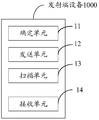
- FIG. 8 is a schematic structural diagram of a device at a transmitting end according to an embodiment of the present disclosure.
- FIG. 9 is a schematic structural diagram of a receiving end device according to an embodiment of the present disclosure.
- FIG. 10 is a schematic structural diagram of another transmitting end device according to an embodiment of the present disclosure.
- FIG. 11 is a schematic structural diagram of another receiving end device according to an embodiment of the present invention.
- FIG. 1 is a schematic structural diagram of a communication system according to an embodiment of the present invention.
- the system includes a receiving end device and a transmitting end device.
- the receiving end device of the embodiment of the present invention may communicate with one or more core networks via a Radio Access Network (RAN), and the receiving end device may refer to an access terminal, a subscriber unit, a subscriber station, a mobile station, and a mobile station.
- RAN Radio Access Network
- the access terminal may be a cellular phone, a cordless phone, a Session Initiation Protocol ("SSIP”) phone, a Wireless Local Loop (WLL) station, and a personal digital processing (Personal Digital) Assistant (referred to as "PDA"), a handheld device with wireless communication function, a computing device or other processing device connected to a wireless modem, an in-vehicle device, a wearable device, a terminal device (User Equipment, UE) in a future 5G network, etc. .
- SSIP Session Initiation Protocol
- WLL Wireless Local Loop
- PDA Personal Digital Processing
- UE User Equipment
- the transmitting end device of the embodiment of the present invention may be a transmitting end device of a next generation communication, such as a 5G wireless access network device (New Radio, NR, or "new generation air interface technology"), a transmitting device or a small station, and a micro device. Station, as well as the TRP described earlier.
- a 5G wireless access network device New Radio, NR, or "new generation air interface technology”
- NR New Radio
- new generation air interface technology a transmitting device or a small station
- TRP micro device. Station
- the transmitting device 102 may include multiple antenna groups. Each antenna group may include one or more antennas, for example, one antenna group may include antennas 104 and 106, another antenna group may include antennas 108 and 110, and an additional group may include antennas 112 and 114. Two antennas are shown in Figure 1 for each antenna group, although more or fewer antennas may be used for each group.
- the transmitting device 102 may additionally include a transmitter chain and a receiver chain, as will be understood by those of ordinary skill in the art, which may include various components related to signal transmission and reception, such as a processor, a modulator, a multiplexer, Demodulator, demultiplexer or antenna.
- the transmitting device 102 can communicate with one or more receiving devices, such as the receiving device 116 and the receiving device 122. However, it will be appreciated that the transmitting device 102 can communicate with any number of receiving devices similar to the receiving device 116 or 122. As shown in FIG. 2, the receiving device 116 is in communication with antennas 112 and 114, wherein the antennas 112 and 114 transmit information to the receiving device 116 over the forward link 118 and receive information from the receiving device 116 over the reverse link 120. . In addition, the sink device 122 communicates with the antennas 104 and 106, wherein the antennas 104 and 106 transmit information to the sink device 122 over the forward link 124 and receive information from the sink device 122 over the reverse link 126.
- the forward link 118 can utilize a different frequency band than that used by the reverse link 120, and the forward link 124 can utilize the reverse link 126. Different frequency bands used.
- the forward link 118 and the reverse link 120 can use a common frequency band, and the forward link 124 and the reverse link 126 can use a common frequency band.
- Each set of antennas and/or regions designed for communication is referred to as a sector of the transmitting device 102.
- the antenna group can be designed to communicate with a sink device in a sector of the coverage area of the transmitting device 102.
- the transmitting antenna of the transmitting end device 102 can utilize beamforming to improve the signal to noise of the forward links 118 and 124. ratio.
- the transmitting end device 102 uses beamforming to transmit signals to the randomly dispersed receiving end devices 116 and 122 in the relevant coverage area, as compared to the manner in which the transmitting end device transmits signals to all of its access receiving end devices through a single antenna. Mobile devices in neighboring cells are subject to less interference.
- the transmitting device 102 can be a wireless communication transmitting device, and the receiving device 116 or the receiving device 122 can be a wireless communication receiving device.
- the wireless communication transmitting device can encode the data for transmission.
- the wireless communication transmitting device may acquire, for example, generate, receive from another communication device, or save in a memory, etc., a certain number of data bits to be transmitted to the wireless communication receiving device through the channel.
- Such data bits may be included in a transport block or a plurality of transport blocks of data, and the transport blocks may be segmented to produce a plurality of code blocks.
- FIG. 2 is a schematic diagram of interaction of a beam matching method according to an embodiment of the present invention. The method includes the following steps:
- the transmitting device determines a beam scanning parameter group.
- the transmitting device needs to perform beam scanning according to the beam scanning parameter, and the receiving device needs to perform beam matching according to the beam scanning parameter indicated by the transmitting device, and beam scanning and beam matching involve multiple processes, and each process in the prior art is based on A set of independent parameters performs beam scanning and matching.
- the transmitting end device determines a beam scanning parameter group for performing transmission and reception beam scanning, and the beam scanning parameter group is adapted to multiple beam scanning and matching processes, which is a Group uniform parameters.
- the transmitting device performs a transmit beam scan, where the transmit beam can be used for sending, for example, but not limited to, Channel State Information-Reference Signal (CSI-RS); the receiving device performs beam matching, ie : Align the receive beam of the receiving device with the transmit beam of the transmitting device. After the beam scanning and matching are completed, the transmitting device and the receiving device can use the matched transmitting beam and the receiving beam for data transmission.
- CSI-RS Channel State Information-Reference Signal
- the beam scanning parameter group includes:
- a first quantity parameter Ntot wherein the first quantity parameter is used to indicate a number of unique time units included in at least one consecutive CSI-RS transmission period required to complete beam matching, wherein the unique time unit is Determining one of at least one time unit included in at least one consecutive CSI-RS transmission period, and the transmission beam associated with the unique time unit is different from other time units in the at least one consecutive CSI-RS transmission period An associated transmit beam, and/or a receive beam associated with the unique time unit is different from a receive beam associated with other time units in the at least one consecutive CSI-RS transmission period;
- the scan type includes a first scan type and a second scan type, the first scan type being used to indicate that the transmit beams on different CSI-RS resources and/or ports in each unique time unit are the same
- the second scan type is used to indicate that different CSI-RS resources and/or transmit beams on the port are different in each unique time unit;
- resource parameter is used to indicate one or more CSI-RS resources corresponding to each of the unique time units included in each CSI-RS transmission period.
- the beam scanning parameter set may further include a second quantity parameter Np, where the Np is used to indicate the number of time units included in each of the CSI-RS transmission periods.
- performing beam scanning and matching may require one or more consecutive CSI-RS transmission periods, for example, sending the first CSI-RS to occupy X subframes, and the second CSI-RS in the (X+N)th subframe.
- the CSI-RS transmission period is N subframes, where X ⁇ 1.
- a CSI-RS resource refers to a set of Resource Elements (REs) that can be sent on a group of ports.
- a group of ports includes one or more ports, and a group of REs includes one or more REs.
- One transmit beam may correspond to one or more CSI-RS resources, or one or more ports corresponding to one CSI-RS resource.
- the first scan type refers to multiple ports corresponding to multiple CSI-RS resources or one CSI-RS resource in one unique time unit, that is, multiple CSI-RS resources or one CSI-RS resource.
- the transmit beams corresponding to the multiple ports are the same.
- the second scan type refers to one port corresponding to one CSI-RS resource or one CSI-RS in each unique time unit, that is, the multiple CSI-RS resources or
- the transmit beams corresponding to multiple ports of one CSI-RS resource are different.
- each parameter in the beam scanning parameter set will be described in detail in the multiple beam scanning and matching processes of the latter examples. Different beam matching operations can be performed by different combinations of various parameters.
- multiple CSI-RS resources corresponding to each unique time unit may be time division multiplexed (TDM), frequency division multiplexed. (Frequency Division Multiplexing, FDM), and TDM and FDM are multiplexed.
- TDM time division multiplexed
- FDM Frequency Division Multiplexing
- the multiple CSI-RS resources corresponding to each of the unique time units may be configured in the same one subframe or consecutive multiple subframes, that is, one subframe may be sent more.
- the CSI-RS resources for example, transmit 4 beams in a unique time unit, TxB1 ⁇ TxB4, and each transmit beam corresponds to one CSI-RS resource, and the TxB1 ⁇ TxB4 configuration may be sent in one subframe, or may be TxB1 and The TxB2 configuration is sent on the first subframe, and the TxB3 and TxB4 configurations are sent on the second subframe.
- the configuration of each CSI-RS resource includes at least the following configuration parameters: the number of ports of the CSI-RS resource, the time-frequency density, and the period, that is, the completion of beam scanning and matching may be required.
- the CSI-RS resources need to complete beam scanning and matching in multiple consecutive CSI-RS transmission periods.
- One CSI-RS resource may correspond to multiple ports.
- each CSI- In the RS resource configuration the configuration parameters such as the number of ports, time-frequency density, and period of the CSI-RS resources are guaranteed to be the same.
- the transmitting end device sends the beam scanning parameter group to a receiving end device.
- the transmitting device After the transmitting device establishes a connection with the receiving device and the transmitting device determines the beam scanning parameter group, the transmitting device sends the beam scanning parameter group to the receiving device through signaling, and the receiving device receives the beam scanning parameter from the transmitting device. group. Further, after receiving the beam scanning parameter set sent by the transmitting end device, the receiving end device may store the beam scanning parameter group, and when the receiving end device needs to perform beam matching with the transmitting end device, obtain the storage of the self. Beam scan parameter set.
- the transmitting end device performs transmit beam scanning based on the beam scanning parameter group.
- the transmitting device sends the transmitting beam according to the received beam scanning parameter group, that is, transmits the transmitting beam according to the first quantity parameter, the scanning type and the resource parameter.
- the receiving end device performs beam matching based on the beam scanning parameter group.
- the receiving end device performs the matching of the receiving beam on the transmitting beam that is detected by the transmitting end device based on the beam scanning parameter group, so that the receiving beam of the transmitting end device is aligned with the transmitting beam of the transmitting end device, that is, the beam scanning parameter group is used to determine the specific A set of transmit beams and receive beams are aligned, and then S104 specifically includes: performing, for the transmit end device, a transmit beam that is determined by using a beam scan parameter group based on the beam scan parameter set, and acquiring, according to the beam scan parameter set, a match with the transmit beam. Receive beam.
- a beam scanning and matching process is: the transmitting end device scans a plurality of transmitted wide beams to determine one or more beams with better transmit beam quality, and the receiving end device transmits multiple widths.
- the beam performs beam matching to determine a receiving beam that matches one or more transmitting beams determined by the transmitting device; another beam scanning and matching process is that the receiving beam matched by the receiving device remains unchanged, and is determined for the transmitting end scanning.
- Wide beam, scanning determines a plurality of narrow beams in the wide beam, and determining a narrow beam aligned with the receiving beam; another beam scanning and matching process is that the transmitting beam remains unchanged and is determined in multiple receiving beams A receive beam that matches the transmit beam.
- the above beam matching process is a process of scanning the measurement to obtain a beam with a good transmit beam or a good receive beam, which is a process in which a receive beam is aligned with a transmit beam.
- the method may further include the following steps:
- the receiving end device sends a beam matching result to the transmitting end device.
- the beam matching result includes information about a transmit beam determined by the receiving end device to perform beam matching based on the beam scanning parameter group;
- the beam matching result includes a number of a unique time unit corresponding to the determined transmit beam, and/or a port number of the CSI-RS resource, if the unique time unit corresponds to one CSI-RS resource;
- the beam matching result includes a number of a unique time unit corresponding to the determined transmit beam, and/or a resource number of the CSI-RS resource, and/or The port number of the CSI-RS resource.
- the receiving device may also report the beam quality.
- the multiplexing methods of the CSI-RS resources in the following examples are all TDM, and the FDM, or TDM and FDM multiplexing situations are similar:
- FIGS. 4a-4c are schematic diagrams of a beam scanning and matching process for determining one or more wide beams from a plurality of transmitted wide beams and determining the same according to an embodiment of the present invention.
- the beam matching process can perform beam matching in a centralized or distributed manner:
- the STUs in the figure correspond to one CSI-RS resource and/or port. It can be seen that the transmit beams corresponding to each STU are the same in each TU. Therefore, the transmit beam scan type is The first scan type.
- the transmitting end device transmits a beam according to the above parameter group, that is, performs beam scanning, and the receiving end device can also determine which one of the receiving beams aligned with the transmitting beam according to the above parameter group, for example, assuming that the transmitting end device performs transmission beam scanning, at TxB1 ⁇
- the wide beam in TxB4 that determines the better beam quality is TxB2, and here the receiving device uses two receiving beams RxB1 and RxB2 for beam matching, and the receiving device can determine that the receiving beam aligned with TxB2 is RxB1 according to the above parameter group.
- the beam matching result includes: a TU number.
- the scan type is the second scan type.
- the receiving end device performs beam matching result reporting, if each TU corresponds to one CSI-RS resource, and the CSI-RS resource further includes multiple ports, that is, the transmitting beam is multiple corresponding to the one CSI-RS resource. If the port sends the result, the beam matching result includes: a port number of the CSI-RS resource.
- the beam matching result includes: a CSI-RS resource number; Corresponding to a plurality of CSI-RS resources, and each CSI-RS resource corresponds to multiple ports, and different ports can send different transmit beams, and the beam matching result includes: a CSI-RS resource number and a port of the CSI-RS resource. number.
- the first scan type is used in FIG. 4a, indicating that the receive beam is switched faster than the transmit beam
- the second scan type in FIG. 4b indicates that the transmit beam is switched faster than the receive beam
- the transmit beam corresponding to each STU is different. Therefore, the transmit beam scan type is the second scan type.
- four beams are transmitted in the TU, that is, TxB1 to TxB4, and one receiving beam is used for beam matching in each period of the TU, and beam scanning and matching are completed through multiple cycles. Therefore, it is called distributed. Beam matching.
- the transmitting device transmits a beam according to the above parameter group, that is, performs beam scanning, and the receiving device can determine which one of the receiving beams is aligned with the transmitting beam according to the above parameter group. For example, it is assumed that the transmitting device performs the beam scanning to determine the beam quality.
- the good wide beam is TxB2, and here the receiving end device uses multiple receiving beams for beam matching, and one receiving beam is used for beam matching in each cycle, and the receiving end device can determine that the receiving beam aligned with TxB2 is according to the above parameter group. RxB3.
- the receiving end device performs beam matching result reporting, if the TU corresponds to one CSI-RS resource, and the CSI-RS resource further includes multiple ports, that is, the transmitting beam is multiple ports corresponding to the one CSI-RS resource. If the signal is sent, the beam matching result includes the CSI-RS port number. If the TU corresponds to multiple CSI-RS resources, and the transmit beams sent by one or more ports corresponding to each CSI-RS resource are the same, the beam matching result includes: the resource number of the CSI-RS.
- the beam matching result includes: the CSI-RS resource number and the CSI-RS.
- the port number of the resource is not limited to the CSI-RS resources, and each CSI-RS resource corresponds to multiple ports.
- the beam scanning and matching process is used for determining a receive beam (ie, receiving beam unchanged) for the foregoing process, in determining A narrow beam aligned with the receive beam is selected in the wide beam, the transmit beam includes a plurality of narrow beams, and the beam matching result includes information of one or more narrow beams determined from the plurality of narrow beams.
- the beam matching process is further divided into periodic/semi-periodic beam matching and non-periodic beam matching:
- the transmit beam includes a plurality of narrow beams that are periodically or semi-periodically transmitted, Ntot ⁇ 1, and the scan type is a second scan type.
- Ntot>1 that is, multiple consecutive CSI-RS transmission periods include multiple unique time units, and each TU is associated with a different transmit beam
- TU1 corresponds to TxB1 ⁇ TxB4
- TU2 corresponds to TxB5 ⁇ TxB8,
- the transmit beam is a narrow beam
- how many narrow beams are included in a wide beam how many transmit beams are scanned here. If the 4 wide beams are determined in Figures 4a to 4c, the N wide beams are included here.
- the transmitting device transmits a beam according to the above parameter group, that is, performs beam scanning, and the receiving device can determine which one of the transmitting beams aligned with the receiving beam according to the above parameter group. For example, it is assumed that the transmitting device performs the beam scanning to determine the beam quality.
- the good narrow beam is TxB5, and the receiving beam remains unchanged.
- the receiving end device can determine that the transmitting beam aligned with the receiving beam RxB1 is TxB5 according to the above parameter group.
- the beam matching result includes: a TU number and a CSI-RS port number. . If the TU corresponds to multiple CSI-RS resources, and each CSI-RS resource corresponds to one port or multiple ports to send the same transmit beam, the beam matching result includes: the TU number and the resource number of the CSI-RS; Each TU corresponds to multiple CSI-RS resources, and each CSI-RS resource corresponds to multiple ports, and different ports can send different transmit beams, and the beam matching result includes: a TU number, a CSI-RS resource number, and the Port number of the CSI-RS resource.
- the receive beam is RxB1 and remains unchanged, and the transmit beam is scanned.
- the transmit beams on different CSI-RS resources and/or ports are different, that is, corresponding to each STU.
- the transmit beam is different, so its transmit beam scan type is the second scan type.
- the transmitting device transmits a beam according to the above parameter group, that is, performs beam scanning, and the receiving device can determine which one of the transmitting beams aligned with the receiving beam according to the above parameter group. For example, it is assumed that the transmitting device performs the beam scanning to determine the beam quality.
- the good narrow beam is TxB3, and the receiving beam remains unchanged.
- the receiving end device can determine that the transmitting beam aligned with the receiving beam RxB1 is TxB3 according to the above parameter group.
- the beam matching result includes: a CSI-RS port number. If the TU corresponds to multiple CSI-RS resources, and each CSI-RS resource corresponds to one port or multiple ports to send the same transmit beam, the beam matching result includes: a CSI-RS resource number; if the TU corresponds to multiple A CSI-RS resource, and each CSI-RS resource corresponds to multiple ports, and different ports can send different transmit beams, and the beam matching result includes: a CSI-RS resource number and a port number of the CSI-RS resource.
- FIGS. 6a-6b are schematic diagrams of still another beam scanning and matching process according to an example of an embodiment of the present invention.
- the beam scanning and matching process is used to determine and narrow based on the determined narrow beam (ie, the transmit beam remains unchanged). Beam-aligned receive beam.
- the beam matching process is further divided into periodic/semi-periodic beam matching and non-periodic beam matching:
- the transmit beam on the port is the same, that is, the transmit beam corresponding to each STU is the same. Therefore, the transmit beam scan type is the first scan type.
- the transmitting end device transmits a beam according to the above parameter group, that is, performs beam scanning, and the receiving end device can also determine which receiving beam is aligned with the transmitting beam according to the above parameter group, for example, the transmitting end device transmitting beam is TxB1, and the receiving end here
- the device uses multiple receiving beams for beam matching, and the receiving device can determine that the receiving beam aligned with TxB1 is RxB3 according to the above parameter group.
- the transmit beam is TxB1 and remains unchanged, and the receive beam is matched.
- the transmit beams on different CSI-RS resources and/or ports are the same, that is, corresponding to each STU.
- the transmit beams are the same, so the transmit beam scan type is the first scan type.
- the transmitting end device transmits a beam according to the above parameter group, that is, performs beam scanning, and the receiving end device can also determine which receiving beam is aligned with the transmitting beam according to the above parameter group, for example, the transmitting end device transmitting beam is TxB1, and the receiving end here
- the device uses multiple receiving beams for beam matching, and the receiving device can determine that the receiving beam aligned with TxB1 is RxB2 according to the above parameter group.
- the beam scanning and matching process shown in Figures 4a-4c (referred to as “flow 1") and the beam scanning and matching process shown in Figures 5a-5b (referred to as “flow 2") are performed separately for beam scanning and
- the report firstly obtains the coarse beam alignment based on the process 1.
- the transmitting device performs the narrow beam alignment, and the receiving device needs to use the receiving beam selected in the foregoing process 1 for narrow beam alignment.
- the receiving device continuously performs the beam tracking of the process 1, for example, periodically reporting the matching result.
- the subsequent process 2 scans with a set of narrow beams near the new coarse beam.
- the transmitting device does not know whether the transmitting device has received the information because the transmitting device does not perform the ACK/NACK indication to the receiving device. Then, after the narrow beam transmission after the reporting time, the receiving device does not know whether to use the previously selected receiving beam or need to update to the newly selected receiving beam. Therefore, when performing the CSI-RS configuration of the process 2, it is necessary to indicate to the receiving device which receiving beam should be used. Since a set of transmit beams of Quasi Co-located (QCL) often correspond to the same receive beam, it can be considered to achieve implicit indication reception by indicating which CSI-RS resource and other CSI-RS resources are QCL. The purpose of the end device receiving the beam.
- QCL Quasi Co-located
- the embodiment may further include a step (not shown): the transmitting end device sends a CSI-RS resource quasi-co-location QCL indication message to the receiving end device, where the indication message is used to indicate that the One or more CSI-RS resources of the plurality of narrow beams and one or more CSI-RS resources that transmit the determined wide beam are QCL; the receiving end device receives the CSI-RS resources sent by the transmitting end device a quasi-co-located QCL indication message; and determining the receive beam according to the indication message.
- a joint beam scanning process is also considered, which is a schematic diagram of another beam scanning and matching process according to an example of the embodiment of the present invention as shown in FIG. 7.
- the process includes the combination of the process 1 and the process 2, Independent CSI-RS resource configuration (as described above) and unified beam scan results are reported to achieve fast beam alignment and feedback overhead savings.
- the receiving device selects the optimal beam pair to be TxB6 and RxB1, and therefore reports the CSI-RS resource number corresponding to TxB6, that is, the beam matching result includes one or more determined in the determined one or more wide beams. Narrow beam information.
- additional signaling is required to instruct the receiving device to perform the joint reporting scan result.
- the CSI-RS resource is used for channel measurement, and in the 5G communication system, CSI-RS resources are also needed for beam matching, and then the same CSI-RS resource may be shared by the two functions, for example, A time/band is configured for channel measurement and another time/band may be configured for beam matching. Therefore, it can be considered that when the CSI-RS is configured at a high layer, those CSI-RS resources shared by the two functions are configured in the same reference signal setting (RS setting), and different functions are reflected in different CSI reporting settings.
- the CSI-RS resource in the RS setting is dynamically configured by layer 1/layer 2 (L1/L2) to correspond to which CSI reporting setting.
- the embodiment may further include the following steps (not shown): the transmitting end device semi-statically configures one or more CSI-RS resources shared by beam matching and channel measurement in the same reference signal setting; The transmitting end device dynamically selects at least one CSI-RS resource from the reference signal setting for beam matching or channel measurement.
- a unified beam scanning parameter group can implement unified management of multiple beam matching processes, and the beam matching process is simplified.
- FIG. 8 is a schematic structural diagram of a device at a transmitting end according to an embodiment of the present invention.
- the transmitting device 1000 includes: a determining unit 11, a transmitting unit 12, and a scanning unit 13; optionally, a receiving unit 14; and, further, a configuration unit and a selecting unit (not shown);
- the determining unit 11 is configured to determine a beam scanning parameter set.
- the transmitting device needs to perform beam scanning according to the beam scanning parameter, and the receiving device needs to perform beam matching according to the beam scanning parameter indicated by the transmitting device, and beam scanning and beam matching involve multiple processes, and each process in the prior art is based on A set of independent parameters performs beam scanning and matching.
- the transmitting end device determines a beam scanning parameter group for performing transmission and reception beam scanning, and the beam scanning parameter group is adapted to multiple beam scanning and matching processes, which is a Group uniform parameters.
- the transmitting device performs a transmit beam scanning, where the transmitting beam can be used for transmitting, for example, but not limited to, CSI-RS; the receiving device performs beam matching, that is, the receiving beam of the receiving device and the transmitting beam of the transmitting device Align. After the beam scanning and matching are completed, the transmitting device and the receiving device can use the matched transmitting beam and the receiving beam for data transmission.
- the beam scanning parameter group includes:
- a first quantity parameter Ntot wherein the first quantity parameter is used to indicate a number of unique time units included in at least one consecutive CSI-RS transmission period required to complete beam matching, wherein the unique time unit is Determining one of at least one time unit included in at least one consecutive CSI-RS transmission period, and the transmission beam associated with the unique time unit is different from other time units in the at least one consecutive CSI-RS transmission period An associated transmit beam, and/or a receive beam associated with the unique time unit is different from a receive beam associated with other time units in the at least one consecutive CSI-RS transmission period;
- the scan type includes a first scan type and a second scan type, the first scan type being used to indicate that the transmit beams on different CSI-RS resources and/or ports in each unique time unit are the same
- the second scan type is used to indicate that different CSI-RS resources and/or transmit beams on the port are different in each unique time unit;
- resource parameter is used to indicate one or more CSI-RS resources corresponding to each of the unique time units included in each CSI-RS transmission period.
- the beam scanning parameter set may further include a second quantity parameter Np, where the Np is used to indicate the number of time units included in each of the CSI-RS transmission periods.
- performing beam scanning and matching may require one or more consecutive CSI-RS transmission periods, for example, sending the first CSI-RS to occupy X subframes, and the second CSI-RS in the (X+N)th subframe.
- the CSI-RS transmission period is N subframes, where X ⁇ 1.
- a CSI-RS resource refers to a group of resource particles that can be sent on a set of ports.
- a group of ports includes one or more ports, and a group of REs includes one or more REs.
- One transmit beam may correspond to one or more CSI-RS resources, or one or more ports corresponding to one CSI-RS resource.
- the first scan type refers to multiple ports corresponding to multiple CSI-RS resources or one CSI-RS resource in one unique time unit, that is, multiple CSI-RS resources or one CSI-RS resource.
- the transmit beams corresponding to the multiple ports are the same.
- the second scan type refers to one port corresponding to one CSI-RS resource or one CSI-RS in each unique time unit, that is, the multiple CSI-RS resources or
- the transmit beams corresponding to multiple ports of one CSI-RS resource are different.
- FIG. 3 a schematic diagram of a CSI-RS resource multiplexing manner, where multiple CSI-RS resources corresponding to each unique time unit may be time division multiplexed, frequency division multiplexed, and TDM and FDM. Reuse.
- the multiple CSI-RS resources corresponding to each of the unique time units may be configured in the same one subframe or consecutive multiple subframes, that is, one subframe may be sent more.
- the CSI-RS resources for example, transmit 4 beams in a unique time unit, TxB1 ⁇ TxB4, and each transmit beam corresponds to one CSI-RS resource, and the TxB1 ⁇ TxB4 configuration may be sent in one subframe, or may be TxB1 and The TxB2 configuration is sent on the first subframe, and the TxB3 and TxB4 configurations are sent on the second subframe.
- the configuration of each CSI-RS resource includes at least the following configuration parameters: the number of ports of the CSI-RS resource, the time-frequency density, and the period, that is, the completion of beam scanning and matching may be required.
- the CSI-RS resources need to complete beam scanning and matching in multiple consecutive CSI-RS transmission periods.
- One CSI-RS resource may correspond to multiple ports.
- each CSI- In the RS resource configuration the configuration parameters such as the number of ports, time-frequency density, and period of the CSI-RS resources are guaranteed to be the same.
- the specific configuration of the beam scanning parameter group is:
- the transmit beam includes a plurality of wide beams periodically transmitted, the beam matching result including information of one or more wide beams determined from the plurality of wide beams.
- the transmitting end device scans multiple transmitted wide beams to determine one or more beams with better transmit beam quality, and the receiving end device performs beam matching, determining and transmitting on multiple transmitted wide beams. One or more transmit beam matched receive beams determined by the end device.
- the beam matching process is done through centralized scanning and matching.
- the beam matching process is done through distributed scanning and matching.
- the transmit beam includes a plurality of narrow beams
- the beam matching result includes information of one or more narrow beams determined from the plurality of narrow beams.
- the receiving beam matched by the receiving end device remains unchanged, and the wide beam determined by the transmitting end scans, scans and determines a plurality of narrow beams in the wide beam, and determines a narrow beam aligned with the receiving beam.
- a set of beam scanning parameters in this implementation is set such that the transmit beam includes a plurality of narrow beams that are periodically or semi-periodically transmitted, Ntot ⁇ 1, and the scan type is a second scan type.
- the beam matching process is completed by periodic or semi-periodical scanning and matching.
- the beam matching process is done by aperiodic scanning and matching.
- the transmit beam remains unchanged, the receive beam that matches the transmit beam is determined among the plurality of receive beams, and the beam matching process is completed by periodic or semi-periodical scanning and matching.
- the transmit beam remains unchanged, the receive beam that matches the transmit beam is determined among the plurality of receive beams, and the beam matching process is completed by aperiodic scanning and matching.
- the sending unit 12 is configured to send the beam scanning parameter group to the receiving end device.
- the sending unit 12 sends the beam scanning parameter group to the receiving device through signaling, and the receiving device receives the beam scanning parameter from the transmitting device. group. Further, after receiving the beam scanning parameter set sent by the transmitting end device, the receiving end device may store the beam scanning parameter group, and when the receiving end device needs to perform beam matching with the transmitting end device, obtain the storage of the self. Beam scan parameter set.
- the scanning unit 13 is configured to perform a transmit beam scan based on the beam scanning parameter set.
- the transmitting device sends the transmitting beam according to the received beam scanning parameter group, that is, transmits the transmitting beam according to the first quantity parameter, the scanning type and the resource parameter.
- the transmitting end device 1000 may further include a receiving unit 14, configured to receive a beam matching result from the receiving end device, where the beam matching result includes the receiving end device Performing beam matching determined transmit beam information based on the beam scan parameter set; wherein, if the unique time unit corresponds to one CSI-RS resource, the beam matching result includes a unique time unit corresponding to the determined transmit beam a number, and/or a port number of the CSI-RS resource; if the unique time unit corresponds to multiple CSI-RS resources, the beam matching result includes a number of a unique time unit corresponding to the determined transmit beam, and / or the resource number of the CSI-RS resource, and / or the port number of the CSI-RS resource.
- a receiving unit 14 configured to receive a beam matching result from the receiving end device, where the beam matching result includes the receiving end device Performing beam matching determined transmit beam information based on the beam scan parameter set; wherein, if the unique time unit corresponds to one CSI-RS resource, the beam matching result includes a unique time
- the beam matching result includes: a number of the TU.
- the beam matching result includes: if each TU corresponds to one CSI-RS resource, and the CSI-RS resource further includes multiple ports, that is, the transmit beam is from the one CSI-RS resource. If the corresponding multiple ports are sent, the beam matching result includes: a port number of the CSI-RS resource.
- the beam matching result includes: a CSI-RS resource number; Corresponding to a plurality of CSI-RS resources, and each CSI-RS resource corresponds to multiple ports, and different ports can send different transmit beams, and the beam matching result includes: a CSI-RS resource number and a port of the CSI-RS resource. number.
- the beam matching result includes: if the TU corresponds to one CSI-RS resource, and the CSI-RS resource further includes multiple ports, that is, the transmit beam is corresponding to the one CSI-RS resource. If the multiple ports are sent, the beam matching result includes the CSI-RS port number. If the TU corresponds to multiple CSI-RS resources, and the transmit beams sent by one or more ports corresponding to each CSI-RS resource are the same, the beam matching result includes: the resource number of the CSI-RS.
- the beam matching result includes: the CSI-RS resource number and the CSI-RS.
- the port number of the resource is not limited to the CSI-RS resources, and each CSI-RS resource corresponds to multiple ports.
- the beam matching result includes: if each TU corresponds to one CSI-RS resource, and the CSI-RS resource further includes multiple ports, the beam matching result includes: TU number and CSI -RS port number. If the TU corresponds to multiple CSI-RS resources, and each CSI-RS resource corresponds to one port or multiple ports to send the same transmit beam, the beam matching result includes: the TU number and the resource number of the CSI-RS; Each TU corresponds to multiple CSI-RS resources, and each CSI-RS resource corresponds to multiple ports, and different ports can send different transmit beams, and the beam matching result includes: a TU number, a CSI-RS resource number, and the Port number of the CSI-RS resource.
- the beam matching result includes: if the TU corresponds to one CSI-RS resource, and the CSI-RS resource further includes multiple ports, the beam matching result includes: CSI-RS port number . If the TU corresponds to multiple CSI-RS resources, and each CSI-RS resource corresponds to one port or multiple ports to send the same transmit beam, the beam matching result includes: a CSI-RS resource number; if the TU corresponds to multiple A CSI-RS resource, and each CSI-RS resource corresponds to multiple ports, and different ports can send different transmit beams, and the beam matching result includes: a CSI-RS resource number and a port number of the CSI-RS resource.
- the receiving device can also report the beam quality, that is, the receiving unit 14 can also be used to receive the beam quality report from the receiving device.
- the sending unit 12 is further configured to send a CSI-RS resource quasi-co-located QCL indication message to the receiving end device, where the indication message is used to indicate one or more used to transmit the multiple narrow beams.
- the CSI-RS resource and one or more CSI-RS resources transmitting the determined wide beam are QCL.
- a joint beam scanning and matching is also considered, the beam matching result including information of one or more narrow beams determined in the determined one or more wide beams.
- Fast beam alignment and feedback overhead savings are achieved through independent CSI-RS resource configuration and unified beam scan result reporting.
- additional signaling is required to instruct the receiving device to perform the joint reporting scan result.
- CSI-RS resources are used for channel measurement.
- CSI-RS resources are also needed for beam matching.
- the same CSI-RS resources may be shared by these two functions, such as a certain moment.
- the /band is configured for channel measurement and may be configured for beam matching at another time/band. Therefore, it can be considered that when the CSI-RS is configured at a high layer, those CSI-RS resources shared by the two functions are configured in the same reference signal setting, and different functions are reflected in different CSI reporting settings.
- a configuration unit configured to semi-statically configure one or more CSI-RS resources shared by beam matching and channel measurement in the same reference signal setting.
- a selecting unit configured to dynamically select at least one CSI-RS resource from the reference signal setting for beam matching or channel measurement.
- a unified beam scanning parameter group can implement unified management of multiple beam matching processes, which simplifies the beam matching process.
- FIG. 9 is a schematic structural diagram of a receiving end device according to an embodiment of the present invention.
- the receiving device 2000 includes: a receiving unit 21 and a matching unit 22; optionally, the receiving device 2000 may further include a sending unit 23;
- the receiving unit 21 is configured to receive a beam scanning parameter group from the transmitting end device.
- the transmitting device needs to perform beam scanning according to the beam scanning parameter, and the receiving device needs to perform beam matching according to the beam scanning parameter indicated by the transmitting device, and beam scanning and beam matching involve multiple processes, and each process in the prior art is based on A set of independent parameters performs beam scanning and matching.
- the transmitting end device determines a beam scanning parameter group for performing transmission and reception beam scanning, and the beam scanning parameter group is adapted to multiple beam scanning and matching processes, which is a Group uniform parameters.
- the transmitting device performs a transmit beam scanning, where the transmitting beam can be used for transmitting, for example, but not limited to, CSI-RS; the receiving device performs beam matching, that is, the receiving beam of the receiving device and the transmitting beam of the transmitting device Align. After the beam scanning and matching are completed, the transmitting device and the receiving device can use the matched transmitting beam and the receiving beam for data transmission.
- the transmitting device After the transmitting device establishes a connection with the receiving device and the transmitting device determines the beam scanning parameter group, the transmitting device sends the beam scanning parameter group to the receiving device through signaling, and the receiving unit 21 receives the beam scanning parameter from the transmitting device. group. Further, after the receiving unit 21 receives the beam scanning parameter set sent by the transmitting end device, the receiving end device may store the beam scanning parameter group, and when the receiving end device needs to perform beam matching with the transmitting end device, obtain The beam scanning parameter set stored by itself.
- the beam scanning parameter group includes:
- a first quantity parameter Ntot wherein the first quantity parameter is used to indicate a number of unique time units included in at least one consecutive CSI-RS transmission period required to complete beam matching, wherein the unique time unit is Determining one of at least one time unit included in at least one consecutive CSI-RS transmission period, and the transmission beam associated with the unique time unit is different from other time units in the at least one consecutive CSI-RS transmission period An associated transmit beam, and/or a receive beam associated with the unique time unit is different from a receive beam associated with other time units in the at least one consecutive CSI-RS transmission period;
- the scan type includes a first scan type and a second scan type, the first scan type being used to indicate that the transmit beams on different CSI-RS resources and/or ports in each unique time unit are the same
- the second scan type is used to indicate that different CSI-RS resources and/or transmit beams on the port are different in each unique time unit;
- resource parameter is used to indicate one or more CSI-RS resources corresponding to each of the unique time units included in each CSI-RS transmission period.
- the beam scanning parameter set may further include a second quantity parameter Np, where the Np is used to indicate the number of time units included in each of the CSI-RS transmission periods.
- performing beam scanning and matching may require one or more consecutive CSI-RS transmission periods, for example, sending the first CSI-RS to occupy X subframes, and the second CSI-RS in the (X+N)th subframe.
- the CSI-RS transmission period is N subframes, where X ⁇ 1.
- a CSI-RS resource refers to a group of resource particles that can be sent on a set of ports.
- a group of ports includes one or more ports, and a group of REs includes one or more REs.
- One transmit beam may correspond to one or more CSI-RS resources, or one or more ports corresponding to one CSI-RS resource.
- the first scan type refers to multiple ports corresponding to multiple CSI-RS resources or one CSI-RS resource in one unique time unit, that is, multiple CSI-RS resources or one CSI-RS resource.
- the transmit beams corresponding to the multiple ports are the same.
- the second scan type refers to one port corresponding to one CSI-RS resource or one CSI-RS in each unique time unit, that is, the multiple CSI-RS resources or
- the transmit beams corresponding to multiple ports of one CSI-RS resource are different.
- FIG. 3 a schematic diagram of a CSI-RS resource multiplexing manner, where multiple CSI-RS resources corresponding to each unique time unit may be time division multiplexed, frequency division multiplexed, and TDM and FDM. Reuse.
- the multiple CSI-RS resources corresponding to each of the unique time units may be configured in the same one subframe or consecutive multiple subframes, that is, one subframe may be sent more.
- the CSI-RS resources for example, transmit 4 beams in a unique time unit, TxB1 ⁇ TxB4, and each transmit beam corresponds to one CSI-RS resource, and the TxB1 ⁇ TxB4 configuration may be sent in one subframe, or may be TxB1 and The TxB2 configuration is sent on the first subframe, and the TxB3 and TxB4 configurations are sent on the second subframe.
- the configuration of each CSI-RS resource includes at least the following configuration parameters: the number of ports of the CSI-RS resource, the time-frequency density, and the period, that is, the completion of beam scanning and matching may be required.
- the CSI-RS resources need to complete beam scanning and matching in multiple consecutive CSI-RS transmission periods.
- One CSI-RS resource may correspond to multiple ports.
- each CSI- In the RS resource configuration the configuration parameters such as the number of ports, time-frequency density, and period of the CSI-RS resources are guaranteed to be the same.
- the specific configuration of the beam scanning parameter group is:
- the transmit beam includes a plurality of wide beams periodically transmitted, the beam matching result including information of one or more wide beams determined from the plurality of wide beams.
- the transmitting end device scans multiple transmitted wide beams to determine one or more beams with better transmit beam quality, and the receiving end device performs beam matching, determining and transmitting on multiple transmitted wide beams. One or more transmit beam matched receive beams determined by the end device.
- the beam matching process is done through centralized scanning and matching.
- the beam matching process is done through distributed scanning and matching.
- the transmit beam includes a plurality of narrow beams
- the beam matching result includes information of one or more narrow beams determined from the plurality of narrow beams.
- the receiving beam matched by the receiving end device remains unchanged, and the wide beam determined by the transmitting end scans, scans and determines a plurality of narrow beams in the wide beam, and determines a narrow beam aligned with the receiving beam.
- a set of beam scanning parameters in this implementation is set such that the transmit beam includes a plurality of narrow beams that are periodically or semi-periodically transmitted, Ntot ⁇ 1, and the scan type is a second scan type.
- the beam matching process is completed by periodic or semi-periodical scanning and matching.
- the beam matching process is done by aperiodic scanning and matching.
- the transmit beam remains unchanged, the receive beam that matches the transmit beam is determined among the plurality of receive beams, and the beam matching process is completed by periodic or semi-periodical scanning and matching.
- the transmit beam remains unchanged, the receive beam that matches the transmit beam is determined among the plurality of receive beams, and the beam matching process is completed by aperiodic scanning and matching.
- the matching unit 22 is configured to perform beam matching based on the beam scanning parameter group.
- the matching unit 22 performs matching of the received beam on the transmit beam determined by the transmitting end device based on the beam scanning parameter group, so that the receiving beam of the transmitting device is aligned with the transmitting beam of the transmitting device, that is, the beam scanning parameter group is used to determine which is specific.
- a set of transmit beams and receive beams are aligned, and the matching unit 22 is specifically configured to: perform, for the transmit end device, a transmit beam determined by the beam scan parameter group based on the beam scan parameter set, and acquire the transmit based on the beam scan parameter set Beam matched receive beam.
- a beam scanning and matching process is: the transmitting end device scans a plurality of transmitted wide beams to determine one or more beams with better transmit beam quality, and the receiving end device transmits multiple widths.
- the beam performs beam matching to determine a receiving beam that matches one or more transmitting beams determined by the transmitting device; another beam scanning and matching process is that the receiving beam matched by the receiving device remains unchanged, and is determined for the transmitting end scanning.
- Wide beam, scanning determines a plurality of narrow beams in the wide beam, and determining a narrow beam aligned with the receiving beam; another beam scanning and matching process is that the transmitting beam remains unchanged and is determined in multiple receiving beams A receive beam that matches the transmit beam.
- the above beam matching process is a process of scanning the measurement to obtain a beam with a good transmit beam or a good receive beam, which is a process in which a receive beam is aligned with a transmit beam.
- the receiving end device 2000 may further include a sending unit 23, where the sending unit 23 is configured to send a beam matching result to the transmitting end device, where the beam matching result includes the beam scanning parameter based on the beam scanning parameter.
- the group performs beam matching to determine the information of the transmit beam; wherein, if the unique time unit corresponds to one CSI-RS resource, the beam matching result includes a number of the unique time unit corresponding to the determined transmit beam, and/or a port number of the CSI-RS resource; if the unique time unit corresponds to multiple CSI-RS resources, the beam matching result includes a number of a unique time unit corresponding to the determined transmit beam, and/or the CSI- The resource number of the RS resource, and/or the port number of the CSI-RS resource.
- the beam matching result includes: a number of the TU.
- the beam matching result includes: if each TU corresponds to one CSI-RS resource, and the CSI-RS resource further includes multiple ports, that is, the transmit beam is from the one CSI-RS resource. If the corresponding multiple ports are sent, the beam matching result includes: a port number of the CSI-RS resource.
- the beam matching result includes: a CSI-RS resource number; Corresponding to a plurality of CSI-RS resources, and each CSI-RS resource corresponds to multiple ports, and different ports can send different transmit beams, and the beam matching result includes: a CSI-RS resource number and a port of the CSI-RS resource. number.
- the beam matching result includes: if the TU corresponds to one CSI-RS resource, and the CSI-RS resource further includes multiple ports, that is, the transmit beam is corresponding to the one CSI-RS resource. If the multiple ports are sent, the beam matching result includes the CSI-RS port number. If the TU corresponds to multiple CSI-RS resources, and the transmit beams sent by one or more ports corresponding to each CSI-RS resource are the same, the beam matching result includes: the resource number of the CSI-RS.
- the beam matching result includes: the CSI-RS resource number and the CSI-RS.
- the port number of the resource is not limited to the CSI-RS resources, and each CSI-RS resource corresponds to multiple ports.
- the beam matching result includes: if each TU corresponds to one CSI-RS resource, and the CSI-RS resource further includes multiple ports, the beam matching result includes: TU number and CSI -RS port number. If the TU corresponds to multiple CSI-RS resources, and each CSI-RS resource corresponds to one port or multiple ports to send the same transmit beam, the beam matching result includes: the TU number and the resource number of the CSI-RS; Each TU corresponds to multiple CSI-RS resources, and each CSI-RS resource corresponds to multiple ports, and different ports can send different transmit beams, and the beam matching result includes: a TU number, a CSI-RS resource number, and the Port number of the CSI-RS resource.
- the beam matching result includes: if the TU corresponds to one CSI-RS resource, and the CSI-RS resource further includes multiple ports, the beam matching result includes: CSI-RS port number . If the TU corresponds to multiple CSI-RS resources, and each CSI-RS resource corresponds to one port or multiple ports to send the same transmit beam, the beam matching result includes: a CSI-RS resource number; if the TU corresponds to multiple A CSI-RS resource, and each CSI-RS resource corresponds to multiple ports, and different ports can send different transmit beams, and the beam matching result includes: a CSI-RS resource number and a port number of the CSI-RS resource.
- the receiving device can also report the beam quality, that is, the sending unit 23 can also be used to report the beam quality to the transmitting device.
- the receiving unit 21 is further configured to receive a CSI-RS resource quasi-co-located QCL indication message sent by the transmitting end device, where the indication message is used to indicate one or more used to transmit the multiple narrow beams.
- the CSI-RS resource and the one or more CSI-RS resources that transmit the determined wide beam are QCL
- the matching unit 22 is further configured to determine the receive beam according to the indication message.
- a joint beam scanning and matching is also considered, the beam matching result including information of one or more narrow beams determined in the determined one or more wide beams.
- Fast beam alignment and feedback overhead savings are achieved through independent CSI-RS resource configuration and unified beam scan result reporting.
- additional signaling is required to instruct the receiving device to perform the joint reporting scan result.
- a unified beam scanning parameter group can implement unified management of multiple beam matching processes, which simplifies the beam matching process.
- FIG. 10 is a schematic structural diagram of another transmitting end device according to an embodiment of the present invention.
- the transmitting end device 3000 may include a transmitter 31, a receiver 32, a processor 33, and a memory 34, and a transmitter 31.
- the receiver 32, the processor 33, and the memory 34 are connected to the bus 35, respectively.
- the processor 33 controls the operation of the transmitting device 3000, which may also be referred to as a Central Processing Unit (CPU).
- Processor 33 may be an integrated circuit chip with signal processing capabilities.
- the processor 33 can also be a general-purpose processor, a digital signal processing (DSP), an application specific integrated circuit (ASIC), a field-programmable gate array (FPGA), or the like. Programmable logic devices, discrete gates or transistor logic devices, discrete hardware components.
- the general purpose processor may be a microprocessor or the processor or any conventional processor or the like.
- the memory 34 stores a set of program codes, and the processor 33 is configured to call the program code stored in the memory 34 for performing the following operations:
- Transmit beam scanning is performed based on the beam scanning parameter set.
- the transmitting end device performs beam scanning based on the determined beam scanning parameter group, and sends the beam scanning parameter group to the receiving end device, so that the receiving end device performs the scan determination based on the beam scanning parameter group.
- the beam scanning parameter group can be used in any beam matching process, so that a unified beam scanning parameter group can realize unified management of multiple beam matching processes and simplify the beam matching process.
- the beam scanning parameter group includes:
- a first quantity parameter Ntot wherein the first quantity parameter is used to indicate at least one consecutive channel state information required to complete beam matching - a number of unique time units included in a reference signal CSI-RS transmission period, where
- the unique time unit is one of at least one time unit included in the at least one consecutive CSI-RS transmission period, and the transmit beam associated with the unique time unit is different from the at least one consecutive CSI-RS transmission a transmit beam associated with other time units in the cycle, and/or a receive beam associated with the unique time unit is different from a receive beam associated with other time units in the at least one consecutive CSI-RS transmission period;
- the scan type includes a first scan type and a second scan type, the first scan type being used to indicate that the transmit beams on different CSI-RS resources and/or ports in each unique time unit are the same
- the second scan type is used to indicate that different CSI-RS resources and/or transmit beams on the port are different in each unique time unit;
- resource parameter is used to indicate one or more CSI-RS resources corresponding to each of the unique time units included in each CSI-RS transmission period.
- the transmitting end device and the receiving end device can perform any beam matching process according to the three unified parameters.
- the multiple CSI-RS resources corresponding to each of the unique time units are configured in the same one subframe or consecutive multiple subframes, and/or the configuration of each CSI-RS resource is at least The following configuration parameters are included: the number of ports of the CSI-RS resource, the time-frequency density, and the period.
- each unique time unit performs CSI-RS resource configuration based on some of the same configuration parameters, which simplifies configuration.
- processor 33 is further configured to perform the following operations:
- the beam matching result includes information of a transmitting beam that the receiving end device performs beam matching determination based on the beam scanning parameter group;
- the beam matching result includes a number of a unique time unit corresponding to the determined transmit beam, and/or a port number of the CSI-RS resource, if the unique time unit corresponds to one CSI-RS resource;
- the beam matching result includes a number of a unique time unit corresponding to the determined transmit beam, and/or a resource number of the CSI-RS resource, and/or The port number of the CSI-RS resource.
- the receiving end device needs to report the beam matching result to the transmitting end device, and informs the beam beam to determine the transmitted beam information.
- the transmit beam includes a plurality of wide beams periodically transmitted, the beam matching result including information of one or more wide beams determined from the plurality of wide beams.
- the transmitting end device scans multiple transmitted wide beams to determine one or more beams with better transmit beam quality, and the receiving end device performs beam matching, determining and transmitting on multiple transmitted wide beams. One or more transmit beam matched receive beams determined by the end device.
- the beam matching process is accomplished by centralized scanning and matching.
- Ntot 1
- the scan type is a second scan type
- the beam matching process is accomplished by distributed scanning and matching.
- the transmit beam includes a plurality of narrow beams
- the beam matching result includes information of one or more narrow beams determined from the plurality of narrow beams.
- the receiving beam matched by the receiving end device remains unchanged, and the wide beam determined by the transmitting end scans, scans and determines a plurality of narrow beams in the wide beam, and determines a narrow beam aligned with the receiving beam.
- the transmit beam includes a plurality of narrow beams that are periodically or semi-periodically transmitted, Ntot ⁇ 1, and the scan type is a second scan type.
- the beam matching process is accomplished by periodic or semi-periodical scanning and matching.
- the beam matching process is done by aperiodic scanning and matching.
- processor 33 is further configured to perform the following operations:
- CSI-RS resource quasi-co-located QCL indication message Sending a CSI-RS resource quasi-co-located QCL indication message to the receiving end device, where the indication message is used to indicate one or more CSI-RS resources for transmitting the multiple narrow beams and transmit the determined width
- One or more CSI-RS resources of the beam are QCL.
- the purpose of implicitly indicating the receiving end device receiving beam can be achieved.
- the beam matching result includes information of one or more narrow beams determined in the determined one or more wide beams.
- the two processes perform joint beamforming result reporting, which can save feedback overhead of the receiving device.
- the transmit beam remains unchanged, the receive beam that matches the transmit beam is determined among the plurality of receive beams, and the beam matching process is completed by periodic or semi-periodical scanning and matching.
- the transmit beam remains unchanged, the receive beam that matches the transmit beam is determined among the plurality of receive beams, and the beam matching process is completed by aperiodic scanning and matching.
- processor 33 is further configured to perform the following operations:
- One or more CSI-RS resources shared by beam matching and channel measurement are semi-statically configured in the same reference signal setting;
- At least one CSI-RS resource is dynamically selected from the reference signal settings for beam matching or channel measurement.
- CSI-RS resources can be multiplexed in beam matching and channel measurements.
- a unified beam scanning parameter group can implement unified management of multiple beam matching processes, which simplifies the beam matching process.
- FIG. 11 is a schematic structural diagram of another receiving end device according to an embodiment of the present invention.
- the receiving end device 4000 may include a transmitter 41, a receiver 42, a processor 43, and a memory 44, and a transmitter 41.
- Receiver 42, processor 43, and memory 44 are coupled to bus 45, respectively.
- the processor 43 controls the operation of the sink device 4000, which may also be referred to as a central processing unit (CPU).
- Processor 43 may be an integrated circuit chip with signal processing capabilities.
- the processor 43 can also be a general-purpose processor, a digital signal processing (DSP), an application specific integrated circuit (ASIC), a field-programmable gate array (FPGA), or the like. Programmable logic devices, discrete gates or transistor logic devices, discrete hardware components.
- the general purpose processor may be a microprocessor or the processor or any conventional processor or the like.
- the memory 44 stores a set of program codes, and the processor 43 is configured to call the program code stored in the memory 44 for performing the following operations:
- Beam matching is performed based on the beam scanning parameter set.
- the transmitting end device performs beam scanning based on the determined beam scanning parameter group, and sends the beam scanning parameter group to the receiving end device, and the receiving end device also performs the scanning and determining the transmitting beam based on the beam scanning parameter group.
- the beam scanning parameter group can be used in any beam matching process, so that a unified beam scanning parameter group can realize unified management of multiple beam matching processes and simplify the beam matching process.
- the performing beam matching based on the beam scanning parameter group includes:
- beam matching is a transmit beam determined for beam scanning, and a receive beam that matches the transmit beam is acquired.
- the beam scanning parameter group includes:
- a first quantity parameter Ntot wherein the first quantity parameter is used to indicate the number of unique time units included in the at least one consecutive channel state information-reference signal CSI-RS transmission period required to complete the beam matching, wherein
- the unique time unit is one of at least one time unit included in the at least one consecutive CSI-RS transmission period, and the transmit beam associated with the unique time unit is different from the at least one consecutive CSI- a transmit beam associated with other time units in the RS transmission period, and/or a receive beam associated with the unique time unit is different from a receive beam associated with other time units in the at least one consecutive CSI-RS transmission period;
- the scan type includes a first scan type and a second scan type, the first scan type being used to indicate that the transmit beams on different CSI-RS resources and/or ports in each unique time unit are the same
- the second scan type is used to indicate that different CSI-RS resources and/or transmit beams on the port are different in each unique time unit;
- resource parameter is used to indicate one or more CSI-RS resources corresponding to each of the unique time units included in each CSI-RS transmission period.
- the transmitting end device and the receiving end device can perform any beam matching process according to the three unified parameters.
- processor 43 is further configured to perform the following operations:
- the beam matching result includes information of a transmit beam determined by performing beam matching determination based on the beam scanning parameter set;
- the beam matching result includes a number of a unique time unit corresponding to the determined transmit beam, and/or a port number of the CSI-RS resource, if the unique time unit corresponds to one CSI-RS resource;
- the beam matching result includes a number of a unique time unit corresponding to the determined transmit beam, and/or a resource number of the CSI-RS resource, and/or The port number of the CSI-RS resource.
- the receiving end device needs to report the beam matching result to the transmitting end device, and informs the beam beam to determine the transmitted beam information.
- the transmit beam includes a plurality of wide beams periodically transmitted, the beam matching result including information of one or more wide beams determined from the plurality of wide beams.
- the transmitting end device scans multiple transmitted wide beams to determine one or more beams with better transmit beam quality, and the receiving end device performs beam matching, determining and transmitting on multiple transmitted wide beams. One or more transmit beam matched receive beams determined by the end device.
- the beam matching process is accomplished by centralized scanning and matching.
- Ntot 1
- the scan type is a second scan type
- the beam matching process is accomplished by distributed scanning and matching.
- the transmit beam includes a plurality of narrow beams
- the beam matching result includes information of one or more narrow beams determined from the plurality of narrow beams.
- the receiving beam matched by the receiving end device remains unchanged, and the wide beam determined by the transmitting end scans, scans and determines a plurality of narrow beams in the wide beam, and determines a narrow beam aligned with the receiving beam.
- the transmit beam includes a plurality of narrow beams that are periodically or semi-periodically transmitted, Ntot ⁇ 1, and the scan type is a second scan type.
- the beam matching process is accomplished by periodic or semi-periodical scanning and matching.
- the beam matching process is done by aperiodic scanning and matching.
- processor 43 is further configured to perform the following operations:
- a CSI-RS resource quasi-co-location QCL indication message sent by the transmitting end device where the indication message is used to indicate one or more CSI-RS resources for transmitting the multiple narrow beams and transmitting the determined One or more CSI-RS resources of the wide beam are QCL;
- the purpose of implicitly indicating the receiving end device receiving beam can be achieved.
- the beam matching result includes information of one or more narrow beams determined in the determined one or more wide beams.
- the two processes perform joint beamforming result reporting, which can save feedback overhead of the receiving device.
- the transmit beam remains unchanged, the receive beam that matches the transmit beam is determined among the plurality of receive beams, and the beam matching process is completed by periodic or semi-periodical scanning and matching.
- the transmit beam remains unchanged, the receive beam that matches the transmit beam is determined among the plurality of receive beams, and the beam matching process is completed by aperiodic scanning and matching.
- a unified beam scanning parameter group can implement unified management of multiple beam matching processes, which simplifies the beam matching process.
- Computer readable media includes both computer storage media and communication media including any medium that facilitates transfer of a computer program from one location to another.
- a storage medium may be any available media that can be accessed by a computer.
- the computer readable medium may include a random access memory (RAM), a read-only memory (ROM), and an electrically erasable programmable read-only memory (Electrically Erasable Programmable).
- EEPROM Electrically Error Read-Only Memory
- CD-ROM Compact Disc Read-Only Memory
- Any connection may suitably be a computer readable medium.
- the software is transmitted from a website, server, or other remote source using coaxial cable, fiber optic cable, twisted pair, Digital Subscriber Line (DSL), or wireless technologies such as infrared, radio, and microwave, Then coaxial cable, fiber optic cable, twisted pair, DSL or wireless technologies such as infrared, wireless and microwave are included in the fixing of the associated medium.
- DSL Digital Subscriber Line
- a disk and a disc include a compact disc (CD), a laser disc, a compact disc, a digital versatile disc (DVD), a floppy disc, and a Blu-ray disc, wherein the disc is usually magnetically copied, and the disc is The laser is used to optically replicate the data. Combinations of the above should also be included within the scope of the computer readable media.
Landscapes
- Engineering & Computer Science (AREA)
- Signal Processing (AREA)
- Computer Networks & Wireless Communication (AREA)
- Quality & Reliability (AREA)
- Mobile Radio Communication Systems (AREA)
Abstract
本发明实施例提供一种波束匹配方法及装置。一种波束匹配方法包括:确定波束扫描参数组;发送所述波束扫描参数组至接收端设备;基于所述波束扫描参数组进行发射波束扫描;另一种波束匹配方法包括:接收来自发射端设备的波束扫描参数组;基于所述波束扫描参数组执行波束匹配。还公开了相应的装置。通过一个统一的波束扫描参数组可以实现对多种波束匹配流程的统一管理,简化了波束匹配流程。
Description
本申请要求于2017年01月06日提交中国专利局、申请号为201710010982.6、申请名称为“一种波束匹配方法及装置”的中国专利申请的优先权,其全部内容通过引用结合在本申请中。
本发明涉及通信技术领域,尤其涉及一种波束匹配方法及装置。
当前,下一代演进系统在网络性能及用户体验方面有着更高要求,给第五代移动通信系统(5
th-Generation,5G)带来了更大挑战。毫米波频段由于其频谱资源丰富,成为5G技术的主要工作频段之一。使用毫米波频段时,由于其频段在数据传输过程中的路径损耗大,抗衰落性能差,通过需要发送窄波束来提高覆盖。窄波束的应用可以对抗高频的路径损耗,提高覆盖,但是一个关键问题是如何通过波束扫描来实现基站发波束和用户收波束的选择和对准,即波束匹配。
波束匹配流程主要包括:
–终端设备测量不同的发送和接收节点(Transmission and Reception point,TRP)发波束用于选择TRP发波束和终端设备收波束;
–终端设备测量不同的TRP发波束用于可能产生的TRP发波束改变;
–终端设备测量相同的TRP发波束用于终端设备收波束改变。
如何实现对这多种波束匹配流程的统一管理,是5G系统需要解决的关键问题。
发明内容
本发明实施例提供一种波束匹配流程及装置,以实现对这多种波束匹配流程的统一管理。
第一方面,提供了一种波束匹配方法,包括:确定波束扫描参数组;发送所述波束扫描参数组至接收端设备;基于所述波束扫描参数组进行发射波束扫描。
在该实现方式中,发射端设备基于确定的波束扫描参数组进行波束扫描,并将该波束扫描参数组发送给接收端设备,以使接收端设备也基于该波束扫描参数组进行与扫描确定的发射波束的接收波束的匹配,任一波束匹配流程都可采用该波束扫描参数组,从而通过一个统一的波束扫描参数组可以实现对多种波束匹配流程的统一管理,简化了波束匹配流程。
在第一方面的一种实现方式中,所述波束扫描参数组包括:第一数量参数Ntot,其中,所述第一数量参数用于指示完成波束匹配所需要的至少一个连续的信道状态信息-参考信号CSI-RS发送周期所包含的唯一时间单元的数量,其中,所述唯一时间单元是所述至少一个连续的CSI-RS发送周期所包含的至少一个时间单元的其中一个,且所述唯一时间单元所关联的发射波束不同于所述至少一个连续的CSI-RS发送周期内其他时间单元所关联的发射波束,和/或所述唯一时间单元所关联的接收波束不同于所述至少一个连续的CSI-RS发 送周期内其他时间单元所关联的接收波束;以及扫描类型,其中,所述扫描类型包括第一扫描类型和第二扫描类型,所述第一扫描类型用于表示每个唯一时间单元内的不同CSI-RS资源和/或端口上的发射波束相同,所述第二扫描类型用于表示每个唯一时间单元内的不同CSI-RS资源和/或端口上的发射波束不同;以及资源参数,其中,所述资源参数用于指示每个所述CSI-RS发送周期所包含的每个所述唯一时间单元对应的一个或多个CSI-RS资源。
在该实现方式中,发射端设备和接收端设备根据这三个统一的参数可以执行任一波束匹配流程。
在第一方面的另一种实现方式中,每个所述唯一时间单元对应的多个CSI-RS资源配置在相同的一个子帧或连续的多个子帧上,和/或每个CSI-RS资源的配置至少包括以下相同的配置参数:CSI-RS资源的端口数、时频密度和周期。
在该实现方式中,每个唯一时间单元基于一些相同的配置参数进行CSI-RS资源配置,可以简化配置。
在第一方面的又一种实现方式中,所述方法还包括:接收来自所述接收端设备的波束匹配结果,其中,所述波束匹配结果包括所述接收端设备基于所述波束扫描参数组执行波束匹配确定的发射波束的信息;其中,若所述唯一时间单元对应一个CSI-RS资源,所述波束匹配结果包括所述确定的发射波束对应的唯一时间单元的编号,和/或所述CSI-RS资源的端口号;若所述唯一时间单元对应多个CSI-RS资源,所述波束匹配结果包括所述确定的发射波束对应的唯一时间单元的编号,和/或所述CSI-RS资源的资源编号,和/或所述CSI-RS资源的端口号。
在该实现方式中,对于进行了波束扫描和波束匹配的流程,在波束匹配完成后,接收端设备需向发射端设备上报波束匹配结果,告知执行波束匹配确定的发射波束的信息。
在第一方面的又一种实现方式中,所述发射波束包括周期性地发射的多个宽波束,所述波束匹配结果包括从所述多个宽波束中确定的一个或多个宽波束的信息。
在该实现方式中,发射端设备对发射的多个宽波束进行扫描,确定其中一个或多个发射波束质量较好的波束,接收端设备对发射的多个宽波束进行波束匹配,确定与发射端设备确定的一个或多个发射波束匹配的接收波束。
在第一方面的又一种实现方式中,所述波束扫描参数组还包括:第二数量参数Np,其中,所述Np用于指示每个所述CSI-RS发送周期内所包含的时间单元的数量,Ntot=Np>1,所述扫描类型为第一扫描类型或第二扫描类型。
在该实现方式中,通过集中式扫描和匹配完成波束匹配流程。
在第一方面的又一种实现方式中,Ntot=1,所述扫描类型为第二扫描类型。
在该实现方式中,通过分布式扫描和匹配完成波束匹配流程。
在第一方面的又一种实现方式中,所述发射波束包括多个窄波束,所述波束匹配结果包括从所述多个窄波束中确定的一个或多个窄波束的信息。
在该实现方式中,接收端设备匹配了的接收波束保持不变,针对发射端扫描确定的宽波束,扫描确定该宽波束中的多个窄波束,确定与该接收波束对齐的一个窄波束。
在第一方面的又一种实现方式中,所述发射波束包括周期性或半周期性地发射的多个窄波束,Ntot≥1,所述扫描类型为第二扫描类型。
在该实现方式中,通过周期性或半周期性地扫描和匹配完成波束匹配流程。
在第一方面的又一种实现方式中,所述发射波束包括非周期性地发射的多个窄波束,Ntot=1,所述扫描类型为第二扫描类型。
在该实现方式中,通过非周期性地扫描和匹配完成波束匹配流程。
在第一方面的又一种实现方式中,所述方法还包括:向所述接收端设备发送CSI-RS资源准共址QCL指示消息,所述指示消息用于指示用于发射所述多个窄波束的一个或多个CSI-RS资源与发射所述确定的宽波束的一个或多个CSI-RS资源是QCL。
在该实现方式中,通过指示当前CSI-RS资源与其他的哪个CSI-RS资源是QCL,可以达到隐性指示接收端设备接收波束的目的。
在第一方面的又一种实现方式中,所述波束匹配结果包括在确定的一个或多个宽波束中确定的一个或多个窄波束的信息。
在该实现方式中,两个流程进行联合的波束匹配结果上报,可以节省接收端设备的反馈开销。
在第一方面的又一种实现方式中,所述发射波束包括周期性或半周期性地发射的同一个窄波束,Ntot=1,且每个周期只有一个TU,所述扫描类型为第一扫描类型。
在该实现方式中,发射波束保持不变,在多个接收波束中确定与该发射波束匹配的接收波束,通过周期性或半周期性地扫描和匹配完成波束匹配流程。
在第一方面的又一种实现方式中,所述发射波束包括非周期性地发射同一个窄波束,Ntot=1,所述扫描类型为第一扫描类型。
在该实现方式中,发射波束保持不变,在多个接收波束中确定与该发射波束匹配的接收波束,通过非周期性地扫描和匹配完成波束匹配流程。
在第一方面的又一种实现方式中,所述方法还包括:将波束匹配和信道测量共享的一个或多个CSI-RS资源半静态配置在相同的参考信号设置中;从所述参考信号设置中动态选择至少一个CSI-RS资源用于波束匹配或信道测量。
在该实现方式中,CSI-RS资源可在波束匹配和信道测量中复用。
第二方面,提供了一种发射端设备,该发射端设备具有实现上述方法中发射端设备行为的功能。所述功能可以通过硬件实现,也可以通过硬件执行相应的软件实现。所述硬件或软件包括一个或多个与上述功能相对应的模块。
一种可能的实现方式中,所述发射端设备包括:确定单元,用于确定波束扫描参数组;发送单元,用于发送所述确定单元确定的所述波束扫描参数组至接收端设备;扫描单元,用于基于所述确定单元确定的所述波束扫描参数组进行发射波束扫描。
另一种可能的实现方式中,所述发射端设备包括:接收器、发射器、存储器和处理器;其中,存储器中存储一组程序代码,且处理器用于调用存储器中存储的程序代码,执行以下操作:确定波束扫描参数组;发送所述波束扫描参数组至接收端设备;基于所述波束扫描参数组进行发射波束扫描。
基于同一发明构思,由于该装置解决问题的原理以及有益效果可以参见上述第一方面和第一方面的各可能的实施方式以及所带来的有益效果,因此该装置的实施可以参见方法的实施,重复之处不再赘述。
第三方面,提供了一种波束匹配方法,包括:接收来自发射端设备的波束扫描参数组;基于所述波束扫描参数组执行波束匹配。
在该实现方式中,发射端设备基于确定的波束扫描参数组进行波束扫描,并将该波束扫描参数组发送给接收端设备,接收端设备也基于该波束扫描参数组进行与扫描确定的发射波束的接收波束的匹配,任一波束匹配流程都可采用该波束扫描参数组,从而通过一个统一的波束扫描参数组可以实现对多种波束匹配流程的统一管理,简化了波束匹配流程。
在第三方面的一种实现方式中,所述基于所述波束扫描参数组执行波束匹配,包括:针对所述发射端设备基于所述波束扫描参数组执行波束扫描确定的发射波束,基于所述波束扫描参数组获取与所述发射波束匹配的接收波束。
在该实现方式中,波束匹配是针对波束扫描确定的发射波束,获取与该发射波束匹配的接收波束。
在第三方面的另一种实现方式中,所述波束扫描参数组包括:第一数量参数Ntot,其中,所述第一数量参数用于指示完成所述波束匹配所需要的至少一个连续的信道状态信息-参考信号CSI-RS发送周期所包含的唯一时间单元的数量,其中,所述唯一时间单元是所述至少一个连续的CSI-RS发送周期所包含的至少一个时间单元的其中一个,且所述唯一时间单元所关联的发射波束不同于所述至少一个连续的CSI-RS发送周期内其他时间单元所关联的发射波束,和/或所述唯一时间单元所关联的接收波束不同于所述至少一个连续的CSI-RS发送周期内其他时间单元所关联的接收波束;以及扫描类型,其中,所述扫描类型包括第一扫描类型和第二扫描类型,所述第一扫描类型用于表示每个唯一时间单元内的不同CSI-RS资源和/或端口上的发射波束相同,所述第二扫描类型用于表示每个唯一时间单元内的不同CSI-RS资源和/或端口上的发射波束不同;以及资源参数,其中,所述资源参数用于指示每个所述CSI-RS发送周期所包含的每个所述唯一时间单元对应的一个或多个CSI-RS资源。
在该实现方式中,发射端设备和接收端设备根据这三个统一的参数可以执行任一波束匹配流程。
在第三方面的又一种实现方式中,所述方法还包括:向所述发射端设备发送波束匹配结果,其中,所述波束匹配结果包括基于所述波束扫描参数组执行波束匹配确定的发射波束的信息;其中,若所述唯一时间单元对应一个CSI-RS资源,所述波束匹配结果包括所述确定的发射波束对应的唯一时间单元的编号,和/或所述CSI-RS资源的端口号;若所述唯一时间单元对应多个CSI-RS资源,所述波束匹配结果包括所述确定的发射波束对应的唯一时间单元的编号,和/或所述CSI-RS资源的资源编号,和/或所述CSI-RS资源的端口号。
在该实现方式中,对于进行了波束扫描和波束匹配的流程,在波束匹配完成后,接收端设备需向发射端设备上报波束匹配结果,告知执行波束匹配确定的发射波束的信息。
在第三方面的又一种实现方式中,所述发射波束包括周期性地发射的多个宽波束,所述波束匹配结果包括从所述多个宽波束中确定的一个或多个宽波束的信息。
在该实现方式中,发射端设备对发射的多个宽波束进行扫描,确定其中一个或多个发射波束质量较好的波束,接收端设备对发射的多个宽波束进行波束匹配,确定与发射端设备确定的一个或多个发射波束匹配的接收波束。
在第三方面的又一种实现方式中,所述波束扫描参数组还包括:第二数量参数Np,其中,所述Np用于指示每个所述CSI-RS发送周期内所包含的时间单元的数量,Ntot=Np>1,所述扫描类型为第一扫描类型或第二扫描类型。
在该实现方式中,通过集中式扫描和匹配完成波束匹配流程。
在第三方面的又一种实现方式中,Ntot=1,所述扫描类型为第二扫描类型。
在该实现方式中,通过分布式扫描和匹配完成波束匹配流程。
在第三方面的又一种实现方式中,所述发射波束包括多个窄波束,所述波束匹配结果包括从所述多个窄波束中确定的一个或多个窄波束的信息。
在该实现方式中,接收端设备匹配了的接收波束保持不变,针对发射端扫描确定的宽波束,扫描确定该宽波束中的多个窄波束,确定与该接收波束对齐的一个窄波束。
在第三方面的又一种实现方式中,所述发射波束包括周期性或半周期性地发射的多个窄波束,Ntot≥1,所述扫描类型为第二扫描类型。
在该实现方式中,通过周期性或半周期性地扫描和匹配完成波束匹配流程。
在第三方面的又一种实现方式中,所述发射波束包括非周期性地发射的多个窄波束,Ntot=1,所述扫描类型为第二扫描类型。
在该实现方式中,通过非周期性地扫描和匹配完成波束匹配流程。
在第三方面的又一种实现方式中,所述方法还包括:接收所述发射端设备发送的CSI-RS资源准共址QCL指示消息,所述指示消息用于指示用于发射所述多个窄波束的一个或多个CSI-RS资源与发射所述确定的宽波束的一个或多个CSI-RS资源是QCL;根据所述指示消息确定所述接收波束。
在该实现方式中,通过指示当前CSI-RS资源与其他的哪个CSI-RS资源是QCL,可以达到隐性指示接收端设备接收波束的目的。
在第三方面的又一种实现方式中,所述波束匹配结果包括在确定的一个或多个宽波束中确定的一个或多个窄波束的信息。
在该实现方式中,两个流程进行联合的波束匹配结果上报,可以节省接收端设备的反馈开销。
在第三方面的又一种实现方式中,所述发射波束包括周期性或半周期性地发射的同一个窄波束,Ntot=1,且每个周期只有一个TU,所述扫描类型为第一扫描类型。
在该实现方式中,发射波束保持不变,在多个接收波束中确定与该发射波束匹配的接收波束,通过周期性或半周期性地扫描和匹配完成波束匹配流程。
在第三方面的又一种实现方式中,所述发射波束包括非周期性地发射同一个窄波束,Ntot=1,所述扫描类型为第一扫描类型。
在该实现方式中,发射波束保持不变,在多个接收波束中确定与该发射波束匹配的接收波束,通过非周期性地扫描和匹配完成波束匹配流程。
第四方面,提供了一种接收端设备,该接收端设备具有实现上述方法中发射端设备行为的功能。所述功能可以通过硬件实现,也可以通过硬件执行相应的软件实现。所述硬件或软件包括一个或多个与上述功能相对应的模块。
一种可能的实现方式中,所述接收端设备包括:接收单元,用于接收来自发射端设备 的波束扫描参数组;匹配单元,用于基于所述接收单元接收到的所述波束扫描参数组执行波束匹配。
另一种可能的实现方式中,所述接收端设备包括:接收器、发射器、存储器和处理器;其中,存储器中存储一组程序代码,且处理器用于调用存储器中存储的程序代码,执行以下操作:接收来自发射端设备的波束扫描参数组;基于所述波束扫描参数组执行波束匹配。
基于同一发明构思,由于该装置解决问题的原理以及有益效果可以参见上述第三方面和第三方面的各可能的实施方式以及所带来的有益效果,因此该装置的实施可以参见方法的实施,重复之处不再赘述。
图1为本发明实施例涉及的一种通信系统架构示意图;
图2为本发明实施例提供的一种波束匹配方法的交互示意图;
图3为CSI-RS资源复用方式示意图;
图4a-4c为本发明实施例示例的一个波束扫描和匹配流程的示意图;
图5a-5b为本发明实施例示例的另一个波束扫描和匹配流程的示意图;
图6a-6b为本发明实施例示例的又一个波束扫描和匹配流程的示意图;
图7为本发明实施例示例的又一个波束扫描和匹配流程的示意图;
图8为本发明实施例提供的一种发射端设备的结构示意图;
图9为本发明实施例提供的一种接收端设备的结构示意图;
图10为本发明实施例提供的另一种发射端设备的结构示意图;
图11为本发明实施例提供的另一种接收端设备的结构示意图。
下面结合附图,对本发明的实施例进行描述:
请参阅图1,图1为本发明实施例涉及的一种通信系统架构示意图。该系统包括接收端设备和发射端设备。本发明实施例的接收端设备可以经无线接入网(Radio Access Network,RAN)与一个或多个核心网进行通信,接收端设备可以指接入终端、用户单元、用户站、移动站、移动台、远方站、远程终端、移动设备、用户终端、终端、无线通信设备、用户代理或用户装置。接入终端可以是蜂窝电话、无绳电话、会话启动协议(Session Initiation Protocol,简称为“SIP”)电话、无线本地环路(Wireless Local Loop,简称为“WLL”)站、个人数字处理(Personal Digital Assistant,简称为“PDA”)、具有无线通信功能的手持设备、计算设备或连接到无线调制解调器的其它处理设备、车载设备、可穿戴设备,未来5G网络中的终端设备(User Equipment,UE)等。
本发明实施例的发射端设备可以是下一代通信的发射端设备,比如5G的无线接入网设备(New Radio,NR,或称“新一代空口技术”)、发射端设备或小站、微站,以及前面所述的TRP。
具体地,在图1中,发射端设备102可包括多个天线组。每个天线组可以包括一个或多个天线,例如,一个天线组可包括天线104和106,另一个天线组可包括天线108和110,附加组可包括天线112和114。图1中对于每个天线组示出了2个天线,然而可对于每个组 使用更多或更少的天线。发射端设备102可附加地包括发射机链和接收机链,本领域普通技术人员可以理解,它们均可包括与信号发送和接收相关的多个部件,例如处理器、调制器、复用器、解调器、解复用器或天线等。
发射端设备102可以与一个或多个接收端设备,例如接收端设备116和接收端设备122通信。然而,可以理解,发射端设备102可以与类似于接收端设备116或122的任意数目的接收端设备通信。如图2所示,接收端设备116与天线112和114通信,其中天线112和114通过前向链路118向接收端设备116发送信息,并通过反向链路120从接收端设备116接收信息。此外,接收端设备122与天线104和106通信,其中天线104和106通过前向链路124向接收端设备122发送信息,并通过反向链路126从接收端设备122接收信息。在频分双工(Frequency Division Duplex,FDD)系统中,例如,前向链路118可利用与反向链路120所使用的不同频带,前向链路124可利用与反向链路126所使用的不同频带。此外,在时分双工(Time Division Duplex,TDD)系统中,前向链路118和反向链路120可使用共同频带,前向链路124和反向链路126可使用共同频带。
被设计用于通信的每组天线和/或区域称为发射端设备102的扇区。例如,可将天线组设计为与发射端设备102覆盖区域的扇区中的接收端设备通信。在发射端设备102通过前向链路118和124分别与接收端设备116和122进行通信的过程中,发射端设备102的发射天线可利用波束成形来改善前向链路118和124的信噪比。此外,与发射端设备通过单个天线向它所有的接入接收端设备发送信号的方式相比,在发射端设备102利用波束成形向相关覆盖区域中随机分散的接收端设备116和122发送信号时,相邻小区中的移动设备会受到较少的干扰。
在给定时间,发射端设备102可以是无线通信发送装置,接收端设备116或接收端设备122可以是无线通信接收装置。当发送数据时,无线通信发送装置可对数据进行编码以用于传输。具体地,无线通信发送装置可获取,例如生成、从其它通信装置接收、或在存储器中保存等,要通过信道发送至无线通信接收装置的一定数目的数据比特。这种数据比特可包含在数据的传输块或多个传输块中,传输块可被分段以产生多个码块。
请参阅图2,图2为本发明实施例提供的一种波束匹配方法的交互示意图。该方法包括以下步骤:
S101、发射端设备确定波束扫描参数组。
发射端设备需要根据波束扫描参数进行发射波束扫描,接收端设备需要依据发射端设备所指示的波束扫描参数进行波束匹配,而波束扫描和波束匹配涉及多个流程,现有技术中每个流程根据一套独立的参数执行波束扫描和匹配,本实施例中,发射端设备确定执行发射和接收波束扫描的一个波束扫描参数组,该波束扫描参数组适应于多个波束扫描和匹配流程,是一组统一的参数。
发射端设备进行发射波束扫描,在这里,发射波束可以用于发送,例如但不限于,信道状态信息-参考信号(Channel State Information-Reference Signal,CSI-RS);接收端设备进行波束匹配,即:使接收端设备的接收波束与发射端设备的发射波束对齐。波束扫描和匹配完成后,发射端设备和接收端设备就可以采用匹配的发射波束和接收波束进行数据传输。
具体地,该波束扫描参数组包括:
第一数量参数Ntot,其中,所述第一数量参数用于指示完成波束匹配所需要的至少一个连续的CSI-RS发送周期所包含的唯一时间单元的数量,其中,所述唯一时间单元是所述至少一个连续的CSI-RS发送周期所包含的至少一个时间单元的其中一个,且所述唯一时间单元所关联的发射波束不同于所述至少一个连续的CSI-RS发送周期内其他时间单元所关联的发射波束,和/或所述唯一时间单元所关联的接收波束不同于所述至少一个连续的CSI-RS发送周期内其他时间单元所关联的接收波束;以及
扫描类型,其中,所述扫描类型包括第一扫描类型和第二扫描类型,所述第一扫描类型用于表示每个唯一时间单元内的不同CSI-RS资源和/或端口上的发射波束相同,所述第二扫描类型用于表示每个唯一时间单元内的不同CSI-RS资源和/或端口上的发射波束不同;以及
资源参数,其中,所述资源参数用于指示每个所述CSI-RS发送周期所包含的每个所述唯一时间单元对应的一个或多个CSI-RS资源。
可选地,该波束扫描参数组还可以包括第二数量参数Np,其中,所述Np用于指示每个所述CSI-RS发送周期内所包含的时间单元的数量。
具体地,完成波束扫描和匹配可能需要一个或多个连续的CSI-RS发送周期,例如,发送第一个CSI-RS占用X个子帧,第二个CSI-RS在第(X+N)个子帧发送,则CSI-RS发送周期为N个子帧,这里,X≥1。
CSI-RS资源是指可以在一组端口上发送的一组资源粒子(Resource Element,RE),一组端口包括一个或多个端口,一组RE包括一个或多个RE。一个发射波束可以对应一个或多个CSI-RS资源,或者对应一个CSI-RS资源的一个或多个端口。第一扫描类型是指在每个唯一时间单元内,一个发射波束对应多个CSI-RS资源或一个CSI-RS资源的多个端口,即这多个CSI-RS资源或一个CSI-RS资源的多个端口对应的发射波束相同,第二扫描类型是指在每个唯一时间单元内,一个发射波束对应一个CSI-RS资源或一个CSI-RS的一个端口,即这多个CSI-RS资源或一个CSI-RS资源的多个端口对应的发射波束不同。
波束扫描参数组中的各个参数的具体应用在后面示例的多个波束扫描和匹配流程中将详细描述。可以通过各种参数的不同搭配来对应不同的波束匹配操作。
本实施例中,如图3所示的CSI-RS资源复用方式示意图,每个唯一时间单元对应的多个CSI-RS资源可以以时分复用(Time Division Multiplexing,TDM)、频分复用(Frequency Division Multiplexing,FDM)、以及TDM和FDM的方式进行复用。
进一步地,关于CSI-RS资源的配置,每个所述唯一时间单元对应的多个CSI-RS资源可以配置在相同的一个子帧或连续的多个子帧上,即:一个子帧可以发送多个CSI-RS资源,例如一个唯一时间单元内发射4个波束,TxB1~TxB4,每个发射波束对应一个CSI-RS资源,可以是TxB1~TxB4配置在一个子帧上发送,也可以是TxB1和TxB2配置在第一个子帧上发送,TxB3和TxB4配置在第二个子帧上发送。
另外,关于CSI-RS资源的配置,每个CSI-RS资源的配置至少包括以下相同的配置参数:CSI-RS资源的端口数、时频密度和周期,即:完成波束扫描和匹配可能需要多个CSI-RS资源,需要在多个连续的CSI-RS发送周期内完成波束扫描和匹配,一个CSI-RS资源可能对应多个端口,在进行配置时,为了简化资源的配置,每个CSI-RS资源配置中,CSI-RS 资源的端口数、时频密度和周期等这些配置参数保证相同。
S102、所述发射端设备发送所述波束扫描参数组至接收端设备。
在发射端设备与接收端设备建立连接以及发射端设备确定波束扫描参数组后,发射端设备通过信令将波束扫描参数组发送给接收端设备,接收端设备接收来自发射端设备的波束扫描参数组。进一步地,接收端设备接收到发射端设备通过信令发送的波束扫描参数组后,可以将波束扫描参数组进行存储,当接收端设备需要与该发射端设备进行波束匹配时,获取自身存储的波束扫描参数组。
S103、所述发射端设备基于所述波束扫描参数组进行发射波束扫描。
发射端设备根据接收到的波束扫描参数组发送发射波束,即按照第一数量参数、扫描类型和资源参数进行发射波束的发送。
S104、所述接收端设备基于所述波束扫描参数组执行波束匹配。
接收端设备基于该波束扫描参数组对发射端设备扫描确定的发射波束进行接收波束的匹配,使得自身的接收波束与发射端设备的发射波束对齐,即利用该波束扫描参数组来确定具体是哪一组发射波束和接收波束对齐,那么S104具体包括:针对所述发射端设备基于所述波束扫描参数组执行波束扫描确定的发射波束,基于所述波束扫描参数组获取与所述发射波束匹配的接收波束。
具体地,例如,一种波束扫描和匹配流程是,发射端设备对发射的多个宽波束进行扫描,确定其中一个或多个发射波束质量较好的波束,接收端设备对发射的多个宽波束进行波束匹配,确定与发射端设备确定的一个或多个发射波束匹配的接收波束;另一种波束扫描和匹配流程是,接收端设备匹配了的接收波束保持不变,针对发射端扫描确定的宽波束,扫描确定该宽波束中的多个窄波束,确定与该接收波束对齐的一个窄波束;又一种波束扫描和匹配流程是,发射波束保持不变,在多个接收波束中确定与该发射波束匹配的接收波束。以上波束匹配流程都是扫描测量得到发射波束或接收波束质量较好的波束,都是一个接收波束与发射波束对齐的过程。
可选地,该方法还可进一步包括以下步骤:
S105、所述接收端设备向所述发射端设备发送波束匹配结果。
所述波束匹配结果包括所述接收端设备基于所述波束扫描参数组执行波束匹配确定的发射波束的信息;
其中,若所述唯一时间单元对应一个CSI-RS资源,所述波束匹配结果包括所述确定的发射波束对应的唯一时间单元的编号,和/或所述CSI-RS资源的端口号;
若所述唯一时间单元对应多个CSI-RS资源,所述波束匹配结果包括所述确定的发射波束对应的唯一时间单元的编号,和/或所述CSI-RS资源的资源编号,和/或所述CSI-RS资源的端口号。
需要说明的是,接收端设备除了向发射端设备上报波束匹配结果,还可以上报波束质量。
下面结合具体的波束匹配流程来描述波束扫描参数组的具体应用,需要说明的是,下面的示例的CSI-RS资源的复用方式都是TDM,FDM、或TDM和FDM复用的情况类似:
请参阅图4a-4c,为本发明实施例示例的一个波束扫描和匹配流程的示意图,该波束扫 描和匹配流程用于从发射的多个宽波束中确定一个或多个宽波束以及确定与该一个或多个宽波束对齐的接收波束,所述发射波束包括周期性地发射的多个宽波束,所述波束匹配结果包括从所述多个宽波束中确定的一个或多个宽波束的信息。具体地,该波束匹配流程又可以通过集中式或分布式地完成波束匹配:
如图4a所示,为一种集中式的波束匹配流程,所述波束扫描参数组还包括:第二数量参数Np,其中,所述Np用于指示每个所述CSI-RS发送周期内所包含的时间单元的数量,Ntot=Np>1,所述扫描类型为第一扫描类型。
在图4a中,Ntot=4,即多个连续的CSI-RS发送周期中(图中只示例了两个周期)包括4个唯一时间单元(Time Unit,TU),即TU1~TU4,每个TU所关联的发射波束不同,TU1对应TxB1,TU2对应TxB2,以此类推;Np=4,即一个CSI-RS周期内包含4个TU;每个TU内的不同CSI-RS资源和/或端口上的发射波束相同,图中采用“STU”的标号对应一个CSI-RS资源和/或端口,可以看出,每个TU内,各个STU对应的发射波束相同,因此,其发射波束扫描类型为第一扫描类型。发射端设备根据以上参数组发射波束,即进行波束扫描,接收端设备根据以上参数组也能确定与发射波束对齐的接收波束是哪一个,例如,假设发射端设备进行发射波束扫描,在TxB1~TxB4中确定波束质量较好的宽波束为TxB2,而这里接收端设备采用两个接收波束RxB1和RxB2进行波束匹配,接收端设备根据以上参数组能够确定与TxB2对齐的接收波束是RxB1。
另外,接收端设备进行波束匹配结果上报时,该波束匹配结果包括:TU的编号。
如图4b所示,为另一种集中式的波束匹配流程,与图4a所示的集中式的波束匹配流程不同的是,所述扫描类型为第二扫描类型。
在图4b中,Ntot=2,即多个连续的CSI-RS发送周期中包括2个唯一时间单元,即TU1~TU2,每个TU所关联的接收波束不同,TU1对应RxB1,TU2对应RxB2;Np=2,即一个CSI-RS周期内包含2个TU;每个TU内的不同CSI-RS资源和/或端口上的发射波束不同,即每个TU内,每个STU对应的发射波束不同,因此,其发射波束扫描类型为第二扫描类型。
另外,接收端设备进行波束匹配结果上报时,若每个TU对应一个CSI-RS资源,且该CSI-RS资源还包括多个端口,即发射波束是从该一个CSI-RS资源对应的多个端口发送的,则该波束匹配结果包括:CSI-RS资源的端口号。
若每个TU对应多个CSI-RS资源,且每个CSI-RS资源对应一个端口或对应多个端口发送相同的发射波束,则波束匹配结果包括:CSI-RS的资源编号;若每个TU对应多个CSI-RS资源,且每个CSI-RS资源对应多个端口,不同的端口可以发送不同的发射波束,则波束匹配结果包括:CSI-RS的资源编号和该CSI-RS资源的端口号。
可以看出,图4a中采用第一扫描类型,表示接收波束比发射波束切换快,图4b中采用第二扫描类型,则表示发射波束比接收波束切换快。
如图4c所示,为一种分布式的波束匹配流程,Ntot=1,所述扫描类型为第二扫描类型。
在图4c中,Ntot=1,即多个连续的CSI-RS发送周期中包括1个唯一时间单元;该TU内的不同CSI-RS资源和/或端口上的发射波束不同,即该TU内,每个STU对应的发射波束不同,因此,其发射波束扫描类型为第二扫描类型。在图4c中,该TU内发射4个波束, 即TxB1~TxB4,而每个周期的TU内采用一个接收波束进行波束匹配,通过多个周期才完成波束扫描和匹配,因此,称为分布式波束匹配。发射端设备根据以上参数组发射波束,即进行波束扫描,接收端设备根据以上参数组也能确定与发射波束对齐的接收波束是哪一个,例如,假设发射端设备进行发射波束扫描确定波束质量较好的宽波束为TxB2,而这里接收端设备采用多个接收波束进行波束匹配,且每个周期内采用一个接收波束进行波束匹配,接收端设备根据以上参数组能够确定与TxB2对齐的接收波束是RxB3。
另外,接收端设备进行波束匹配结果上报时,若该TU对应一个CSI-RS资源,且该CSI-RS资源还包括多个端口,即发射波束是从该一个CSI-RS资源对应的多个端口发送的,则该波束匹配结果包括CSI-RS端口号即可。若该TU对应多个CSI-RS资源,且每个CSI-RS资源对应的一个或多个端口发送的发射波束相同,则波束匹配结果包括:CSI-RS的资源编号。若该TU对应多个CSI-RS资源,且每个CSI-RS资源对应多个端口,不同的端口可以发送不同的发射波束,则波束匹配结果包括:CSI-RS的资源编号和该CSI-RS资源的端口号。
请参阅图5a-5b,为本发明实施例示例的另一个波束扫描和匹配流程的示意图,该波束扫描和匹配流程用于针对上述流程确定的接收波束(即接收波束不变),在确定的宽波束中选择一个与该接收波束对齐的窄波束,所述发射波束包括多个窄波束,所述波束匹配结果包括从所述多个窄波束中确定的一个或多个窄波束的信息。具体地,该波束匹配流程又分为周期/半周期性波束匹配和非周期性波束匹配:
如图5a所示,所述发射波束包括周期性或半周期性地发射的多个窄波束,Ntot≥1,所述扫描类型为第二扫描类型。
在图5a中,Ntot>1,即多个连续的CSI-RS发送周期中包括多个唯一时间单元,每个TU所关联的发射波束不同,TU1对应TxB1~TxB4,TU2对应TxB5~TxB8,以此类推,这里,发射波束是窄波束,一个宽波束包括多少个窄波束,则这里进行多少个发射波束的扫描,若图4a~4c确定N个宽波束,则这里进行N个宽波束所包含的窄波束的扫描;每个TU内的不同CSI-RS资源和/或端口上的发射波束不同,即每个TU内,每个STU对应的发射波束不同,因此,其发射波束扫描类型为第二扫描类型。发射端设备根据以上参数组发射波束,即进行波束扫描,接收端设备根据以上参数组也能确定与接收波束对齐的发射波束是哪一个,例如,假设发射端设备进行发射波束扫描确定波束质量较好的窄波束为TxB5,而接收波束保持不变,接收端设备根据以上参数组能够确定与接收波束RxB1对齐的发射波束是TxB5。
另外,接收端设备进行波束匹配结果上报时,若每个TU对应一个CSI-RS资源,且该CSI-RS资源还包括多个端口,则该波束匹配结果包括:TU编号和CSI-RS端口号。若每个TU对应多个CSI-RS资源,且每个CSI-RS资源对应一个端口或对应多个端口发送相同的发射波束,则波束匹配结果包括:TU编号和CSI-RS的资源编号;若每个TU对应多个CSI-RS资源,且每个CSI-RS资源对应多个端口,不同的端口可以发送不同的发射波束,则波束匹配结果包括:TU编号、CSI-RS的资源编号和该CSI-RS资源的端口号。
如图5b所示,所述发射波束包括非周期性地发射的多个窄波束,Ntot=1,所述扫描类型为第二扫描类型。
在图5b中,由于是非周期性的,因此只有一个TU,接收波束为RxB1保持不变,进行发射波束扫描;不同CSI-RS资源和/或端口上的发射波束不同,即每个STU对应的发射波束不同,因此,其发射波束扫描类型为第二扫描类型。发射端设备根据以上参数组发射波束,即进行波束扫描,接收端设备根据以上参数组也能确定与接收波束对齐的发射波束是哪一个,例如,假设发射端设备进行发射波束扫描确定波束质量较好的窄波束为TxB3,而接收波束保持不变,接收端设备根据以上参数组能够确定与接收波束RxB1对齐的发射波束是TxB3。
另外,接收端设备进行波束匹配结果上报时,若该TU对应一个CSI-RS资源,且该CSI-RS资源还包括多个端口,则该波束匹配结果包括:CSI-RS端口号。若该TU对应多个CSI-RS资源,且每个CSI-RS资源对应一个端口或对应多个端口发送相同的发射波束,则波束匹配结果包括:CSI-RS的资源编号;若该TU对应多个CSI-RS资源,且每个CSI-RS资源对应多个端口,不同的端口可以发送不同的发射波束,则波束匹配结果包括:CSI-RS的资源编号和该CSI-RS资源的端口号。
请参阅图6a-6b,为本发明实施例示例的又一个波束扫描和匹配流程的示意图,该波束扫描和匹配流程用于基于确定的窄波束(即发射波束保持不变),确定与该窄波束对齐的接收波束。具体地,该波束匹配流程又分为周期/半周期性波束匹配和非周期性波束匹配:
如图6a所示,所述发射波束包括周期性或半周期性地发射的同一个窄波束,Ntot=1,且每个周期只有一个TU,所述扫描类型为第一扫描类型。
在图6a中,发射波束保持不变,即都是发射同一个窄波束TxB1;多个连续的CSI-RS周期或半周期所包含的唯一时间单元的数量Ntot=1;不同CSI-RS资源和/或端口上的发射波束相同,即每个STU对应的发射波束相同,因此,其发射波束扫描类型为第一扫描类型。发射端设备根据以上参数组发射波束,即进行波束扫描,接收端设备根据以上参数组也能确定与发射波束对齐的接收波束是哪一个,例如,发射端设备发射波束为TxB1,而这里接收端设备采用多个接收波束进行波束匹配,接收端设备根据以上参数组能够确定与TxB1对齐的接收波束是RxB3。
如图6b所示,所述发射波束包括非周期性地发射同一个窄波束,Ntot=1,所述扫描类型为第一扫描类型。
在图6b中,由于是非周期性的,因此只有一个TU,发射波束为TxB1保持不变,进行接收波束匹配;不同CSI-RS资源和/或端口上的发射波束相同,即每个STU对应的发射波束相同,因此,其发射波束扫描类型为第一扫描类型。发射端设备根据以上参数组发射波束,即进行波束扫描,接收端设备根据以上参数组也能确定与发射波束对齐的接收波束是哪一个,例如,发射端设备发射波束为TxB1,而这里接收端设备采用多个接收波束进行波束匹配,接收端设备根据以上参数组能够确定与TxB1对齐的接收波束是RxB2。
通常情况下,图4a-4c所示的波束扫描和匹配流程(称为“流程1”)与图5a-5b所示的波束扫描和匹配流程(称为“流程2”)独立进行波束扫描和上报,先基于流程1获取粗波束对准,据此信息发射端设备再执行流程2进行窄波束对准,接收端设备进行窄波束对准时需要使用前面流程1选择的接收波束。接收端设备会持续的进行流程1的波束跟踪,比如周期性上报匹配结果。当选择的粗波束发生改变时,随后进行的流程2会使用新的粗波束附近的 一组窄波束进行扫描。对于通过物理上行链路控制信道(Physical Uplink Control Channel,PUCCH)的扫描结果上报,由于发射端设备不向接收端设备进行ACK/NACK指示,接收端设备不能获知发射端设备是否已经收到该信息,那么在上报时间之后的窄波束的传输,接收端设备不知道是采用之前选择的接收波束还是需要更新为最新选择的接收波束。因此,在进行流程2的CSI-RS配置时,需要向接收端设备指示应该采用哪个接收波束。由于准共址(Quasi Co-located,QCL)的一组发波束往往对应相同的接收波束,因此可以考虑通过指示当前CSI-RS资源与其他的哪个CSI-RS资源是QCL,达到隐性指示接收端设备接收波束的目的。因此,本实施例还可以包括步骤(未示出):所述发射端设备向所述接收端设备发送CSI-RS资源准共址QCL指示消息,所述指示消息用于指示用于发射所述多个窄波束的一个或多个CSI-RS资源与发射所述确定的宽波束的一个或多个CSI-RS资源是QCL;所述接收端设备接收所述发射端设备发送的CSI-RS资源准共址QCL指示消息;并根据所述指示消息确定所述接收波束。
此外,还考虑一种联合的波束扫描流程,如图7所示的本发明实施例示例的又一个波束扫描和匹配流程的示意图,在图7中,包括流程1和流程2的联合进行,通过独立的CSI-RS资源配置(如前述)与统一的波束扫描结果上报来实现快速的波束对准和反馈开销的节省。例如,接收端设备选择最优的波束对是TxB6和RxB1,因此上报TxB6对应的CSI-RS资源编号,即所述波束匹配结果包括在确定的一个或多个宽波束中确定的一个或多个窄波束的信息。为支持这一种方案,还需要额外的信令指示接收端设备进行联合上报扫描结果。
进一步地,一般地,CSI-RS资源用作信道测量,在5G通信系统中还需要采用CSI-RS资源来做波束匹配,那么可能会出现相同的CSI-RS资源被这两个功能共享,比如某一时刻/频段被配置用于信道测量,在另一时刻/频段可能配置用于波束匹配。因此,可以考虑在高层配置CSI-RS时将两种功能共享的那些CSI-RS资源配置在相同的参考信号设置(RS setting)里,不同的功能体现在不同的CSI上报设置(CSI reporting setting)中。通过层1/层2(L1/L2)动态配置该RS setting中的CSI-RS资源与哪个CSI reporting setting对应。因此,本实施例还可包括以下步骤(未示出):所述发射端设备将波束匹配和信道测量共享的一个或多个CSI-RS资源半静态配置在相同的参考信号设置中;以及所述发射端设备从所述参考信号设置中动态选择至少一个CSI-RS资源用于波束匹配或信道测量。
根据本发明实施例提供的一种波束匹配方法,通过一个统一的波束扫描参数组可以实现对多种波束匹配流程的统一管理,简化了波束匹配流程。
需要说明的是,对于前述的方法实施例,为了简单描述,故将其都表述为一系列的动作组合,但是本领域技术人员应该知悉,本发明并不受所描述的动作顺序的限制,因为根据本发明,某些步骤可以采用其他顺序或者同时进行。
请参阅图8,为本发明实施例提供的一种发射端设备的结构示意图。该发射端设备1000包括:确定单元11、发送单元12和扫描单元13;可选地,还可包括接收单元14;进一步地,还可包括配置单元和选择单元(未示出);其中:
确定单元11,用于确定波束扫描参数组。
发射端设备需要根据波束扫描参数进行发射波束扫描,接收端设备需要依据发射端设备所指示的波束扫描参数进行波束匹配,而波束扫描和波束匹配涉及多个流程,现有技术 中每个流程根据一套独立的参数执行波束扫描和匹配,本实施例中,发射端设备确定执行发射和接收波束扫描的一个波束扫描参数组,该波束扫描参数组适应于多个波束扫描和匹配流程,是一组统一的参数。
发射端设备进行发射波束扫描,在这里,发射波束可以用于发送,例如但不限于,CSI-RS;接收端设备进行波束匹配,即:使接收端设备的接收波束与发射端设备的发射波束对齐。波束扫描和匹配完成后,发射端设备和接收端设备就可以采用匹配的发射波束和接收波束进行数据传输。
具体地,该波束扫描参数组包括:
第一数量参数Ntot,其中,所述第一数量参数用于指示完成波束匹配所需要的至少一个连续的CSI-RS发送周期所包含的唯一时间单元的数量,其中,所述唯一时间单元是所述至少一个连续的CSI-RS发送周期所包含的至少一个时间单元的其中一个,且所述唯一时间单元所关联的发射波束不同于所述至少一个连续的CSI-RS发送周期内其他时间单元所关联的发射波束,和/或所述唯一时间单元所关联的接收波束不同于所述至少一个连续的CSI-RS发送周期内其他时间单元所关联的接收波束;以及
扫描类型,其中,所述扫描类型包括第一扫描类型和第二扫描类型,所述第一扫描类型用于表示每个唯一时间单元内的不同CSI-RS资源和/或端口上的发射波束相同,所述第二扫描类型用于表示每个唯一时间单元内的不同CSI-RS资源和/或端口上的发射波束不同;以及
资源参数,其中,所述资源参数用于指示每个所述CSI-RS发送周期所包含的每个所述唯一时间单元对应的一个或多个CSI-RS资源。
可选地,该波束扫描参数组还可以包括第二数量参数Np,其中,所述Np用于指示每个所述CSI-RS发送周期内所包含的时间单元的数量。
具体地,完成波束扫描和匹配可能需要一个或多个连续的CSI-RS发送周期,例如,发送第一个CSI-RS占用X个子帧,第二个CSI-RS在第(X+N)个子帧发送,则CSI-RS发送周期为N个子帧,这里,X≥1。
CSI-RS资源是指可以在一组端口上发送的一组资源粒子,一组端口包括一个或多个端口,一组RE包括一个或多个RE。一个发射波束可以对应一个或多个CSI-RS资源,或者对应一个CSI-RS资源的一个或多个端口。第一扫描类型是指在每个唯一时间单元内,一个发射波束对应多个CSI-RS资源或一个CSI-RS资源的多个端口,即这多个CSI-RS资源或一个CSI-RS资源的多个端口对应的发射波束相同,第二扫描类型是指在每个唯一时间单元内,一个发射波束对应一个CSI-RS资源或一个CSI-RS的一个端口,即这多个CSI-RS资源或一个CSI-RS资源的多个端口对应的发射波束不同。
本实施例中,如图3所示的CSI-RS资源复用方式示意图,每个唯一时间单元对应的多个CSI-RS资源可以以时分复用、频分复用、以及TDM和FDM的方式进行复用。
进一步地,关于CSI-RS资源的配置,每个所述唯一时间单元对应的多个CSI-RS资源可以配置在相同的一个子帧或连续的多个子帧上,即:一个子帧可以发送多个CSI-RS资源,例如一个唯一时间单元内发射4个波束,TxB1~TxB4,每个发射波束对应一个CSI-RS资源,可以是TxB1~TxB4配置在一个子帧上发送,也可以是TxB1和TxB2配置在第一个子帧上 发送,TxB3和TxB4配置在第二个子帧上发送。
另外,关于CSI-RS资源的配置,每个CSI-RS资源的配置至少包括以下相同的配置参数:CSI-RS资源的端口数、时频密度和周期,即:完成波束扫描和匹配可能需要多个CSI-RS资源,需要在多个连续的CSI-RS发送周期内完成波束扫描和匹配,一个CSI-RS资源可能对应多个端口,在进行配置时,为了简化资源的配置,每个CSI-RS资源配置中,CSI-RS资源的端口数、时频密度和周期等这些配置参数保证相同。
在一些具体的波束匹配流程中,该波束扫描参数组的具体配置为:
在一种实现方式中,所述发射波束包括周期性地发射的多个宽波束,所述波束匹配结果包括从所述多个宽波束中确定的一个或多个宽波束的信息。
在该实现方式中,发射端设备对发射的多个宽波束进行扫描,确定其中一个或多个发射波束质量较好的波束,接收端设备对发射的多个宽波束进行波束匹配,确定与发射端设备确定的一个或多个发射波束匹配的接收波束。
在该实现方式中的一种波束扫描参数组设置为:所述波束扫描参数组还包括:第二数量参数Np,其中,所述Np用于指示每个所述CSI-RS发送周期内所包含的时间单元的数量,Ntot=Np>1,所述扫描类型为第一扫描类型或第二扫描类型。
在该设置中,通过集中式扫描和匹配完成波束匹配流程。
在该实现方式中的另一种波束扫描参数组设置为,Ntot=1,所述扫描类型为第二扫描类型。
在该设置中,通过分布式扫描和匹配完成波束匹配流程。
在另一种实现方式中,所述发射波束包括多个窄波束,所述波束匹配结果包括从所述多个窄波束中确定的一个或多个窄波束的信息。
在该实现方式中,接收端设备匹配了的接收波束保持不变,针对发射端扫描确定的宽波束,扫描确定该宽波束中的多个窄波束,确定与该接收波束对齐的一个窄波束。
在该实现方式中的一种波束扫描参数组的设置为:所述发射波束包括周期性或半周期性地发射的多个窄波束,Ntot≥1,所述扫描类型为第二扫描类型。
在该设置中,通过周期性或半周期性地扫描和匹配完成波束匹配流程。
在该实现方式中的另一种波束扫描参数组的设置为:所述发射波束包括非周期性地发射的多个窄波束,Ntot=1,所述扫描类型为第二扫描类型。
在该设置中,通过非周期性地扫描和匹配完成波束匹配流程。
在又一种实现方式中,所述发射波束包括周期性或半周期性地发射的同一个窄波束,Ntot=1,且每个周期只有一个TU,所述扫描类型为第一扫描类型。
在该实现方式中,发射波束保持不变,在多个接收波束中确定与该发射波束匹配的接收波束,通过周期性或半周期性地扫描和匹配完成波束匹配流程。
在又一种实现方式中,所述发射波束包括非周期性地发射同一个窄波束,Ntot=1,所述扫描类型为第一扫描类型。
在该实现方式中,发射波束保持不变,在多个接收波束中确定与该发射波束匹配的接收波束,通过非周期性地扫描和匹配完成波束匹配流程。
发送单元12,用于发送所述波束扫描参数组至接收端设备。
在发射端设备与接收端设备建立连接以及发射端设备确定波束扫描参数组后,发送单元12通过信令将波束扫描参数组发送给接收端设备,接收端设备接收来自发射端设备的波束扫描参数组。进一步地,接收端设备接收到发射端设备通过信令发送的波束扫描参数组后,可以将波束扫描参数组进行存储,当接收端设备需要与该发射端设备进行波束匹配时,获取自身存储的波束扫描参数组。
扫描单元13,用于基于所述波束扫描参数组进行发射波束扫描。
发射端设备根据接收到的波束扫描参数组发送发射波束,即按照第一数量参数、扫描类型和资源参数进行发射波束的发送。
可选地,该发射端设备1000还可进一步包括接收单元14,所述接收单元14,用于接收来自所述接收端设备的波束匹配结果,其中,所述波束匹配结果包括所述接收端设备基于所述波束扫描参数组执行波束匹配确定的发射波束的信息;其中,若所述唯一时间单元对应一个CSI-RS资源,所述波束匹配结果包括所述确定的发射波束对应的唯一时间单元的编号,和/或所述CSI-RS资源的端口号;若所述唯一时间单元对应多个CSI-RS资源,所述波束匹配结果包括所述确定的发射波束对应的唯一时间单元的编号,和/或所述CSI-RS资源的资源编号,和/或所述CSI-RS资源的端口号。
具体地,对于图4a所示的波束匹配流程,该波束匹配结果包括:TU的编号。
对于图4b所示的波束匹配流程,该波束匹配结果包括:若每个TU对应一个CSI-RS资源,且该CSI-RS资源还包括多个端口,即发射波束是从该一个CSI-RS资源对应的多个端口发送的,则该波束匹配结果包括:CSI-RS资源的端口号。若每个TU对应多个CSI-RS资源,且每个CSI-RS资源对应一个端口或对应多个端口发送相同的发射波束,则波束匹配结果包括:CSI-RS的资源编号;若每个TU对应多个CSI-RS资源,且每个CSI-RS资源对应多个端口,不同的端口可以发送不同的发射波束,则波束匹配结果包括:CSI-RS的资源编号和该CSI-RS资源的端口号。
对于图4c所示的波束匹配流程,该波束匹配结果包括:若该TU对应一个CSI-RS资源,且该CSI-RS资源还包括多个端口,即发射波束是从该一个CSI-RS资源对应的多个端口发送的,则该波束匹配结果包括CSI-RS端口号即可。若该TU对应多个CSI-RS资源,且每个CSI-RS资源对应的一个或多个端口发送的发射波束相同,则波束匹配结果包括:CSI-RS的资源编号。若该TU对应多个CSI-RS资源,且每个CSI-RS资源对应多个端口,不同的端口可以发送不同的发射波束,则波束匹配结果包括:CSI-RS的资源编号和该CSI-RS资源的端口号。
对于图5a所示的波束匹配流程,该波束匹配结果包括:若每个TU对应一个CSI-RS资源,且该CSI-RS资源还包括多个端口,则该波束匹配结果包括:TU编号和CSI-RS端口号。若每个TU对应多个CSI-RS资源,且每个CSI-RS资源对应一个端口或对应多个端口发送相同的发射波束,则波束匹配结果包括:TU编号和CSI-RS的资源编号;若每个TU对应多个CSI-RS资源,且每个CSI-RS资源对应多个端口,不同的端口可以发送不同的发射波束,则波束匹配结果包括:TU编号、CSI-RS的资源编号和该CSI-RS资源的端口号。
对于图5b所示的波束匹配流程,该波束匹配结果包括:若该TU对应一个CSI-RS资源,且该CSI-RS资源还包括多个端口,则该波束匹配结果包括:CSI-RS端口号。若该TU 对应多个CSI-RS资源,且每个CSI-RS资源对应一个端口或对应多个端口发送相同的发射波束,则波束匹配结果包括:CSI-RS的资源编号;若该TU对应多个CSI-RS资源,且每个CSI-RS资源对应多个端口,不同的端口可以发送不同的发射波束,则波束匹配结果包括:CSI-RS的资源编号和该CSI-RS资源的端口号。
需要说明的是,接收端设备除了向发射端设备上报波束匹配结果,还可以上报波束质量,即接收单元14还可用于接收来自所述接收端设备的波束质量上报。
进一步地,所述发送单元12还可用于向所述接收端设备发送CSI-RS资源准共址QCL指示消息,所述指示消息用于指示用于发射所述多个窄波束的一个或多个CSI-RS资源与发射所述确定的宽波束的一个或多个CSI-RS资源是QCL。通过指示当前CSI-RS资源与其他的哪个CSI-RS资源是QCL,可以达到隐性指示接收端设备接收波束的目的。
进一步地,还考虑一种联合的波束扫描和匹配,所述波束匹配结果包括在确定的一个或多个宽波束中确定的一个或多个窄波束的信息。通过独立的CSI-RS资源配置与统一的波束扫描结果上报来实现快速的波束对准和反馈开销的节省。为支持这一种方案,还需要额外的信令指示接收端设备进行联合上报扫描结果。
一般地,CSI-RS资源用作信道测量,在5G通信系统中还需要采用CSI-RS资源来做波束匹配,那么可能会出现相同的CSI-RS资源被这两个功能共享,比如某一时刻/频段被配置用于信道测量,在另一时刻/频段可能配置用于波束匹配。因此,可以考虑在高层配置CSI-RS时将两种功能共享的那些CSI-RS资源配置在相同的参考信号设置里,不同的功能体现在不同的CSI上报设置中。通过层1/层2动态配置该参考信号设置中的CSI-RS资源与哪个CSI上报设置对应。因此,进一步地,该发射端设备1000还可包括:配置单元和选择单元(未示出);其中:
配置单元,用于将波束匹配和信道测量共享的一个或多个CSI-RS资源半静态配置在相同的参考信号设置中。
选择单元,用于从所述参考信号设置中动态选择至少一个CSI-RS资源用于波束匹配或信道测量。
根据本发明实施例提供的一种发射端设备,通过一个统一的波束扫描参数组可以实现对多种波束匹配流程的统一管理,简化了波束匹配流程。
请参阅图9,为本发明实施例提供的一种接收端设备的结构示意图。该接收端设备2000包括:接收单元21和匹配单元22;可选地,该接收端设备2000还可进一步包括发送单元23;其中:
接收单元21,用于接收来自发射端设备的波束扫描参数组。
发射端设备需要根据波束扫描参数进行发射波束扫描,接收端设备需要依据发射端设备所指示的波束扫描参数进行波束匹配,而波束扫描和波束匹配涉及多个流程,现有技术中每个流程根据一套独立的参数执行波束扫描和匹配,本实施例中,发射端设备确定执行发射和接收波束扫描的一个波束扫描参数组,该波束扫描参数组适应于多个波束扫描和匹配流程,是一组统一的参数。
发射端设备进行发射波束扫描,在这里,发射波束可以用于发送,例如但不限于,CSI-RS;接收端设备进行波束匹配,即:使接收端设备的接收波束与发射端设备的发射波 束对齐。波束扫描和匹配完成后,发射端设备和接收端设备就可以采用匹配的发射波束和接收波束进行数据传输。
在发射端设备与接收端设备建立连接以及发射端设备确定波束扫描参数组后,发射端设备通过信令将波束扫描参数组发送给接收端设备,接收单元21接收来自发射端设备的波束扫描参数组。进一步地,接收单元21接收到发射端设备通过信令发送的波束扫描参数组后,接收端设备可以将波束扫描参数组进行存储,当接收端设备需要与该发射端设备进行波束匹配时,获取自身存储的波束扫描参数组。
具体地,该波束扫描参数组包括:
第一数量参数Ntot,其中,所述第一数量参数用于指示完成波束匹配所需要的至少一个连续的CSI-RS发送周期所包含的唯一时间单元的数量,其中,所述唯一时间单元是所述至少一个连续的CSI-RS发送周期所包含的至少一个时间单元的其中一个,且所述唯一时间单元所关联的发射波束不同于所述至少一个连续的CSI-RS发送周期内其他时间单元所关联的发射波束,和/或所述唯一时间单元所关联的接收波束不同于所述至少一个连续的CSI-RS发送周期内其他时间单元所关联的接收波束;以及
扫描类型,其中,所述扫描类型包括第一扫描类型和第二扫描类型,所述第一扫描类型用于表示每个唯一时间单元内的不同CSI-RS资源和/或端口上的发射波束相同,所述第二扫描类型用于表示每个唯一时间单元内的不同CSI-RS资源和/或端口上的发射波束不同;以及
资源参数,其中,所述资源参数用于指示每个所述CSI-RS发送周期所包含的每个所述唯一时间单元对应的一个或多个CSI-RS资源。
可选地,该波束扫描参数组还可以包括第二数量参数Np,其中,所述Np用于指示每个所述CSI-RS发送周期内所包含的时间单元的数量。
具体地,完成波束扫描和匹配可能需要一个或多个连续的CSI-RS发送周期,例如,发送第一个CSI-RS占用X个子帧,第二个CSI-RS在第(X+N)个子帧发送,则CSI-RS发送周期为N个子帧,这里,X≥1。
CSI-RS资源是指可以在一组端口上发送的一组资源粒子,一组端口包括一个或多个端口,一组RE包括一个或多个RE。一个发射波束可以对应一个或多个CSI-RS资源,或者对应一个CSI-RS资源的一个或多个端口。第一扫描类型是指在每个唯一时间单元内,一个发射波束对应多个CSI-RS资源或一个CSI-RS资源的多个端口,即这多个CSI-RS资源或一个CSI-RS资源的多个端口对应的发射波束相同,第二扫描类型是指在每个唯一时间单元内,一个发射波束对应一个CSI-RS资源或一个CSI-RS的一个端口,即这多个CSI-RS资源或一个CSI-RS资源的多个端口对应的发射波束不同。
本实施例中,如图3所示的CSI-RS资源复用方式示意图,每个唯一时间单元对应的多个CSI-RS资源可以以时分复用、频分复用、以及TDM和FDM的方式进行复用。
进一步地,关于CSI-RS资源的配置,每个所述唯一时间单元对应的多个CSI-RS资源可以配置在相同的一个子帧或连续的多个子帧上,即:一个子帧可以发送多个CSI-RS资源,例如一个唯一时间单元内发射4个波束,TxB1~TxB4,每个发射波束对应一个CSI-RS资源,可以是TxB1~TxB4配置在一个子帧上发送,也可以是TxB1和TxB2配置在第一个子帧上 发送,TxB3和TxB4配置在第二个子帧上发送。
另外,关于CSI-RS资源的配置,每个CSI-RS资源的配置至少包括以下相同的配置参数:CSI-RS资源的端口数、时频密度和周期,即:完成波束扫描和匹配可能需要多个CSI-RS资源,需要在多个连续的CSI-RS发送周期内完成波束扫描和匹配,一个CSI-RS资源可能对应多个端口,在进行配置时,为了简化资源的配置,每个CSI-RS资源配置中,CSI-RS资源的端口数、时频密度和周期等这些配置参数保证相同。
在一些具体的波束匹配流程中,该波束扫描参数组的具体配置为:
在一种实现方式中,所述发射波束包括周期性地发射的多个宽波束,所述波束匹配结果包括从所述多个宽波束中确定的一个或多个宽波束的信息。
在该实现方式中,发射端设备对发射的多个宽波束进行扫描,确定其中一个或多个发射波束质量较好的波束,接收端设备对发射的多个宽波束进行波束匹配,确定与发射端设备确定的一个或多个发射波束匹配的接收波束。
在该实现方式中的一种波束扫描参数组设置为:所述波束扫描参数组还包括:第二数量参数Np,其中,所述Np用于指示每个所述CSI-RS发送周期内所包含的时间单元的数量,Ntot=Np>1,所述扫描类型为第一扫描类型或第二扫描类型。
在该设置中,通过集中式扫描和匹配完成波束匹配流程。
在该实现方式中的另一种波束扫描参数组设置为,Ntot=1,所述扫描类型为第二扫描类型。
在该设置中,通过分布式扫描和匹配完成波束匹配流程。
在另一种实现方式中,所述发射波束包括多个窄波束,所述波束匹配结果包括从所述多个窄波束中确定的一个或多个窄波束的信息。
在该实现方式中,接收端设备匹配了的接收波束保持不变,针对发射端扫描确定的宽波束,扫描确定该宽波束中的多个窄波束,确定与该接收波束对齐的一个窄波束。
在该实现方式中的一种波束扫描参数组的设置为:所述发射波束包括周期性或半周期性地发射的多个窄波束,Ntot≥1,所述扫描类型为第二扫描类型。
在该设置中,通过周期性或半周期性地扫描和匹配完成波束匹配流程。
在该实现方式中的另一种波束扫描参数组的设置为:所述发射波束包括非周期性地发射的多个窄波束,Ntot=1,所述扫描类型为第二扫描类型。
在该设置中,通过非周期性地扫描和匹配完成波束匹配流程。
在又一种实现方式中,所述发射波束包括周期性或半周期性地发射的同一个窄波束,Ntot=1,且每个周期只有一个TU,所述扫描类型为第一扫描类型。
在该实现方式中,发射波束保持不变,在多个接收波束中确定与该发射波束匹配的接收波束,通过周期性或半周期性地扫描和匹配完成波束匹配流程。
在又一种实现方式中,所述发射波束包括非周期性地发射同一个窄波束,Ntot=1,所述扫描类型为第一扫描类型。
在该实现方式中,发射波束保持不变,在多个接收波束中确定与该发射波束匹配的接收波束,通过非周期性地扫描和匹配完成波束匹配流程。
匹配单元22,用于基于所述波束扫描参数组执行波束匹配。
匹配单元22基于该波束扫描参数组对发射端设备扫描确定的发射波束进行接收波束的匹配,使得自身的接收波束与发射端设备的发射波束对齐,即利用该波束扫描参数组来确定具体是哪一组发射波束和接收波束对齐,那么匹配单元22具体用于:针对所述发射端设备基于所述波束扫描参数组执行波束扫描确定的发射波束,基于所述波束扫描参数组获取与所述发射波束匹配的接收波束。
具体地,例如,一种波束扫描和匹配流程是,发射端设备对发射的多个宽波束进行扫描,确定其中一个或多个发射波束质量较好的波束,接收端设备对发射的多个宽波束进行波束匹配,确定与发射端设备确定的一个或多个发射波束匹配的接收波束;另一种波束扫描和匹配流程是,接收端设备匹配了的接收波束保持不变,针对发射端扫描确定的宽波束,扫描确定该宽波束中的多个窄波束,确定与该接收波束对齐的一个窄波束;又一种波束扫描和匹配流程是,发射波束保持不变,在多个接收波束中确定与该发射波束匹配的接收波束。以上波束匹配流程都是扫描测量得到发射波束或接收波束质量较好的波束,都是一个接收波束与发射波束对齐的过程。
可选地,该接收端设备2000还可进一步包括发送单元23,所述发送单元23,用于向所述发射端设备发送波束匹配结果,其中,所述波束匹配结果包括基于所述波束扫描参数组执行波束匹配确定的发射波束的信息;其中,若所述唯一时间单元对应一个CSI-RS资源,所述波束匹配结果包括所述确定的发射波束对应的唯一时间单元的编号,和/或所述CSI-RS资源的端口号;若所述唯一时间单元对应多个CSI-RS资源,所述波束匹配结果包括所述确定的发射波束对应的唯一时间单元的编号,和/或所述CSI-RS资源的资源编号,和/或所述CSI-RS资源的端口号。
具体地,对于图4a所示的波束匹配流程,该波束匹配结果包括:TU的编号。
对于图4b所示的波束匹配流程,该波束匹配结果包括:若每个TU对应一个CSI-RS资源,且该CSI-RS资源还包括多个端口,即发射波束是从该一个CSI-RS资源对应的多个端口发送的,则该波束匹配结果包括:CSI-RS资源的端口号。若每个TU对应多个CSI-RS资源,且每个CSI-RS资源对应一个端口或对应多个端口发送相同的发射波束,则波束匹配结果包括:CSI-RS的资源编号;若每个TU对应多个CSI-RS资源,且每个CSI-RS资源对应多个端口,不同的端口可以发送不同的发射波束,则波束匹配结果包括:CSI-RS的资源编号和该CSI-RS资源的端口号。
对于图4c所示的波束匹配流程,该波束匹配结果包括:若该TU对应一个CSI-RS资源,且该CSI-RS资源还包括多个端口,即发射波束是从该一个CSI-RS资源对应的多个端口发送的,则该波束匹配结果包括CSI-RS端口号即可。若该TU对应多个CSI-RS资源,且每个CSI-RS资源对应的一个或多个端口发送的发射波束相同,则波束匹配结果包括:CSI-RS的资源编号。若该TU对应多个CSI-RS资源,且每个CSI-RS资源对应多个端口,不同的端口可以发送不同的发射波束,则波束匹配结果包括:CSI-RS的资源编号和该CSI-RS资源的端口号。
对于图5a所示的波束匹配流程,该波束匹配结果包括:若每个TU对应一个CSI-RS资源,且该CSI-RS资源还包括多个端口,则该波束匹配结果包括:TU编号和CSI-RS端口号。若每个TU对应多个CSI-RS资源,且每个CSI-RS资源对应一个端口或对应多个端 口发送相同的发射波束,则波束匹配结果包括:TU编号和CSI-RS的资源编号;若每个TU对应多个CSI-RS资源,且每个CSI-RS资源对应多个端口,不同的端口可以发送不同的发射波束,则波束匹配结果包括:TU编号、CSI-RS的资源编号和该CSI-RS资源的端口号。
对于图5b所示的波束匹配流程,该波束匹配结果包括:若该TU对应一个CSI-RS资源,且该CSI-RS资源还包括多个端口,则该波束匹配结果包括:CSI-RS端口号。若该TU对应多个CSI-RS资源,且每个CSI-RS资源对应一个端口或对应多个端口发送相同的发射波束,则波束匹配结果包括:CSI-RS的资源编号;若该TU对应多个CSI-RS资源,且每个CSI-RS资源对应多个端口,不同的端口可以发送不同的发射波束,则波束匹配结果包括:CSI-RS的资源编号和该CSI-RS资源的端口号。
需要说明的是,接收端设备除了向发射端设备上报波束匹配结果,还可以上报波束质量,即发送单元23还可用于向所述发射端设备上报波束质量。
进一步地,所述接收单元21还可用于接收所述发射端设备发送的CSI-RS资源准共址QCL指示消息,所述指示消息用于指示用于发射所述多个窄波束的一个或多个CSI-RS资源与发射所述确定的宽波束的一个或多个CSI-RS资源是QCL,所述匹配单元22还可用于根据所述指示消息确定所述接收波束。通过指示当前CSI-RS资源与其他的哪个CSI-RS资源是QCL,可以达到隐性指示接收端设备接收波束的目的。
进一步地,还考虑一种联合的波束扫描和匹配,所述波束匹配结果包括在确定的一个或多个宽波束中确定的一个或多个窄波束的信息。通过独立的CSI-RS资源配置与统一的波束扫描结果上报来实现快速的波束对准和反馈开销的节省。为支持这一种方案,还需要额外的信令指示接收端设备进行联合上报扫描结果。
根据本发明实施例提供的一种接收端设备,通过一个统一的波束扫描参数组可以实现对多种波束匹配流程的统一管理,简化了波束匹配流程。
请参阅图10,图10为本发明实施例提供的另一种发射端设备的结构示意图,该发射端设备3000可以包括发射器31、接收器32、处理器33和存储器34,发射器31、接收器32、处理器33和存储器34分别连接总线35。
处理器33控制发射端设备3000的操作,处理器33还可以称为中央处理单元(Central Processing Unit,CPU)。处理器33可能是一种集成电路芯片,具有信号的处理能力。处理器33还可以是通用处理器、数字信号处理器(Digital Signal Processing,DSP)、专用集成电路(Application Specific Integrated Circuit,ASIC)、现场可编程门阵列(Field-Programmable Gate Array,FPGA)或者其他可编程逻辑器件、分立门或者晶体管逻辑器件、分立硬件组件。通用处理器可以是微处理器或者该处理器也可以是任何常规的处理器等。
其中,存储器34中存储一组程序代码,且处理器33用于调用存储器34中存储的程序代码,用于执行以下操作:
确定波束扫描参数组;
发送所述波束扫描参数组至接收端设备;
基于所述波束扫描参数组进行发射波束扫描。
在该实现方式中,发射端设备基于确定的波束扫描参数组进行波束扫描,并将该波束扫描参数组发送给接收端设备,以使接收端设备也基于该波束扫描参数组进行与扫描确定 的发射波束的接收波束的匹配,任一波束匹配流程都可采用该波束扫描参数组,从而通过一个统一的波束扫描参数组可以实现对多种波束匹配流程的统一管理,简化了波束匹配流程。
在一种实现方式中,所述波束扫描参数组包括:
第一数量参数Ntot,其中,所述第一数量参数用于指示完成波束匹配所需要的至少一个连续的信道状态信息-参考信号CSI-RS发送周期所包含的唯一时间单元的数量,其中,所述唯一时间单元是所述至少一个连续的CSI-RS发送周期所包含的至少一个时间单元的其中一个,且所述唯一时间单元所关联的发射波束不同于所述至少一个连续的CSI-RS发送周期内其他时间单元所关联的发射波束,和/或所述唯一时间单元所关联的接收波束不同于所述至少一个连续的CSI-RS发送周期内其他时间单元所关联的接收波束;以及
扫描类型,其中,所述扫描类型包括第一扫描类型和第二扫描类型,所述第一扫描类型用于表示每个唯一时间单元内的不同CSI-RS资源和/或端口上的发射波束相同,所述第二扫描类型用于表示每个唯一时间单元内的不同CSI-RS资源和/或端口上的发射波束不同;以及
资源参数,其中,所述资源参数用于指示每个所述CSI-RS发送周期所包含的每个所述唯一时间单元对应的一个或多个CSI-RS资源。
在该实现方式中,发射端设备和接收端设备根据这三个统一的参数可以执行任一波束匹配流程。
在另一种实现方式中,每个所述唯一时间单元对应的多个CSI-RS资源配置在相同的一个子帧或连续的多个子帧上,和/或每个CSI-RS资源的配置至少包括以下相同的配置参数:CSI-RS资源的端口数、时频密度和周期。
在该实现方式中,每个唯一时间单元基于一些相同的配置参数进行CSI-RS资源配置,可以简化配置。
在又一种实现方式中,所述处理器33还用于执行以下操作:
接收来自所述接收端设备的波束匹配结果,其中,所述波束匹配结果包括所述接收端设备基于所述波束扫描参数组执行波束匹配确定的发射波束的信息;
其中,若所述唯一时间单元对应一个CSI-RS资源,所述波束匹配结果包括所述确定的发射波束对应的唯一时间单元的编号,和/或所述CSI-RS资源的端口号;
若所述唯一时间单元对应多个CSI-RS资源,所述波束匹配结果包括所述确定的发射波束对应的唯一时间单元的编号,和/或所述CSI-RS资源的资源编号,和/或所述CSI-RS资源的端口号。
在该实现方式中,对于进行了波束扫描和波束匹配的流程,在波束匹配完成后,接收端设备需向发射端设备上报波束匹配结果,告知执行波束匹配确定的发射波束的信息。
在又一种实现方式中,所述发射波束包括周期性地发射的多个宽波束,所述波束匹配结果包括从所述多个宽波束中确定的一个或多个宽波束的信息。
在该实现方式中,发射端设备对发射的多个宽波束进行扫描,确定其中一个或多个发射波束质量较好的波束,接收端设备对发射的多个宽波束进行波束匹配,确定与发射端设备确定的一个或多个发射波束匹配的接收波束。
在又一种实现方式中,所述波束扫描参数组还包括:第二数量参数Np,其中,所述Np用于指示每个所述CSI-RS发送周期内所包含的时间单元的数量,Ntot=Np>1,所述扫描类型为第一扫描类型或第二扫描类型。
在该实现方式中,通过集中式扫描和匹配完成波束匹配流程。
在又一种实现方式中,Ntot=1,所述扫描类型为第二扫描类型。
在该实现方式中,通过分布式扫描和匹配完成波束匹配流程。
在又一种实现方式中,所述发射波束包括多个窄波束,所述波束匹配结果包括从所述多个窄波束中确定的一个或多个窄波束的信息。
在该实现方式中,接收端设备匹配了的接收波束保持不变,针对发射端扫描确定的宽波束,扫描确定该宽波束中的多个窄波束,确定与该接收波束对齐的一个窄波束。
在又一种实现方式中,所述发射波束包括周期性或半周期性地发射的多个窄波束,Ntot≥1,所述扫描类型为第二扫描类型。
在该实现方式中,通过周期性或半周期性地扫描和匹配完成波束匹配流程。
在又一种实现方式中,所述发射波束包括非周期性地发射的多个窄波束,Ntot=1,所述扫描类型为第二扫描类型。
在该实现方式中,通过非周期性地扫描和匹配完成波束匹配流程。
在又一种实现方式中,所述处理器33还用于执行以下操作:
向所述接收端设备发送CSI-RS资源准共址QCL指示消息,所述指示消息用于指示用于发射所述多个窄波束的一个或多个CSI-RS资源与发射所述确定的宽波束的一个或多个CSI-RS资源是QCL。
在该实现方式中,通过指示当前CSI-RS资源与其他的哪个CSI-RS资源是QCL,可以达到隐性指示接收端设备接收波束的目的。
在又一种实现方式中,所述波束匹配结果包括在确定的一个或多个宽波束中确定的一个或多个窄波束的信息。
在该实现方式中,两个流程进行联合的波束匹配结果上报,可以节省接收端设备的反馈开销。
在又一种实现方式中,所述发射波束包括周期性或半周期性地发射的同一个窄波束,Ntot=1,且每个周期只有一个TU,所述扫描类型为第一扫描类型。
在该实现方式中,发射波束保持不变,在多个接收波束中确定与该发射波束匹配的接收波束,通过周期性或半周期性地扫描和匹配完成波束匹配流程。
在又一种实现方式中,所述发射波束包括非周期性地发射同一个窄波束,Ntot=1,所述扫描类型为第一扫描类型。
在该实现方式中,发射波束保持不变,在多个接收波束中确定与该发射波束匹配的接收波束,通过非周期性地扫描和匹配完成波束匹配流程。
在又一种实现方式中,所述处理器33还用于执行以下操作:
将波束匹配和信道测量共享的一个或多个CSI-RS资源半静态配置在相同的参考信号设置中;
从所述参考信号设置中动态选择至少一个CSI-RS资源用于波束匹配或信道测量。
在该实现方式中,CSI-RS资源可在波束匹配和信道测量中复用。
根据本发明实施例提供的一种发射端设备,通过一个统一的波束扫描参数组可以实现对多种波束匹配流程的统一管理,简化了波束匹配流程。
请参阅图11,图11为本发明实施例提供的另一种接收端设备的结构示意图,该接收端设备4000可以包括发射器41、接收器42、处理器43和存储器44,发射器41、接收器42、处理器43和存储器44分别连接总线45。
处理器43控制接收端设备4000的操作,处理器43还可以称为中央处理单元(Central Processing Unit,CPU)。处理器43可能是一种集成电路芯片,具有信号的处理能力。处理器43还可以是通用处理器、数字信号处理器(Digital Signal Processing,DSP)、专用集成电路(Application Specific Integrated Circuit,ASIC)、现场可编程门阵列(Field-Programmable Gate Array,FPGA)或者其他可编程逻辑器件、分立门或者晶体管逻辑器件、分立硬件组件。通用处理器可以是微处理器或者该处理器也可以是任何常规的处理器等。
其中,存储器44中存储一组程序代码,且处理器43用于调用存储器44中存储的程序代码,用于执行以下操作:
接收来自发射端设备的波束扫描参数组;
基于所述波束扫描参数组执行波束匹配。
在该实现方式中,发射端设备基于确定的波束扫描参数组进行波束扫描,并将该波束扫描参数组发送给接收端设备,接收端设备也基于该波束扫描参数组进行与扫描确定的发射波束的接收波束的匹配,任一波束匹配流程都可采用该波束扫描参数组,从而通过一个统一的波束扫描参数组可以实现对多种波束匹配流程的统一管理,简化了波束匹配流程。
在一种实现方式中,所述基于所述波束扫描参数组执行波束匹配,包括:
针对所述发射端设备基于所述波束扫描参数组执行波束扫描确定的发射波束,和/或基于所述波束扫描参数组获取与所述发射波束匹配的接收波束。
在该实现方式中,波束匹配是针对波束扫描确定的发射波束,获取与该发射波束匹配的接收波束。
在另一种实现方式中,所述波束扫描参数组包括:
第一数量参数Ntot,其中,所述第一数量参数用于指示完成所述波束匹配所需要的至少一个连续的信道状态信息-参考信号CSI-RS发送周期所包含的唯一时间单元的数量,其中,所述唯一时间单元是所述至少一个连续的CSI-RS发送周期所包含的至少一个时间单元的其中一个,且所述唯一时间单元所关联的发射波束不同于所述至少一个连续的CSI-RS发送周期内其他时间单元所关联的发射波束,和/或所述唯一时间单元所关联的接收波束不同于所述至少一个连续的CSI-RS发送周期内其他时间单元所关联的接收波束;以及
扫描类型,其中,所述扫描类型包括第一扫描类型和第二扫描类型,所述第一扫描类型用于表示每个唯一时间单元内的不同CSI-RS资源和/或端口上的发射波束相同,所述第二扫描类型用于表示每个唯一时间单元内的不同CSI-RS资源和/或端口上的发射波束不同;以及
资源参数,其中,所述资源参数用于指示每个所述CSI-RS发送周期所包含的每个所述唯一时间单元对应的一个或多个CSI-RS资源。
在该实现方式中,发射端设备和接收端设备根据这三个统一的参数可以执行任一波束匹配流程。
在又一种实现方式中,所述处理器43还用于执行以下操作:
向所述发射端设备发送波束匹配结果,其中,所述波束匹配结果包括基于所述波束扫描参数组执行波束匹配确定的发射波束的信息;
其中,若所述唯一时间单元对应一个CSI-RS资源,所述波束匹配结果包括所述确定的发射波束对应的唯一时间单元的编号,和/或所述CSI-RS资源的端口号;
若所述唯一时间单元对应多个CSI-RS资源,所述波束匹配结果包括所述确定的发射波束对应的唯一时间单元的编号,和/或所述CSI-RS资源的资源编号,和/或所述CSI-RS资源的端口号。
在该实现方式中,对于进行了波束扫描和波束匹配的流程,在波束匹配完成后,接收端设备需向发射端设备上报波束匹配结果,告知执行波束匹配确定的发射波束的信息。
在又一种实现方式中,所述发射波束包括周期性地发射的多个宽波束,所述波束匹配结果包括从所述多个宽波束中确定的一个或多个宽波束的信息。
在该实现方式中,发射端设备对发射的多个宽波束进行扫描,确定其中一个或多个发射波束质量较好的波束,接收端设备对发射的多个宽波束进行波束匹配,确定与发射端设备确定的一个或多个发射波束匹配的接收波束。
在又一种实现方式中,所述波束扫描参数组还包括:第二数量参数Np,其中,所述Np用于指示每个所述CSI-RS发送周期内所包含的时间单元的数量,Ntot=Np>1,所述扫描类型为第一扫描类型或第二扫描类型。
在该实现方式中,通过集中式扫描和匹配完成波束匹配流程。
在又一种实现方式中,Ntot=1,所述扫描类型为第二扫描类型。
在该实现方式中,通过分布式扫描和匹配完成波束匹配流程。
在又一种实现方式中,所述发射波束包括多个窄波束,所述波束匹配结果包括从所述多个窄波束中确定的一个或多个窄波束的信息。
在该实现方式中,接收端设备匹配了的接收波束保持不变,针对发射端扫描确定的宽波束,扫描确定该宽波束中的多个窄波束,确定与该接收波束对齐的一个窄波束。
在又一种实现方式中,所述发射波束包括周期性或半周期性地发射的多个窄波束,Ntot≥1,所述扫描类型为第二扫描类型。
在该实现方式中,通过周期性或半周期性地扫描和匹配完成波束匹配流程。
在又一种实现方式中,所述发射波束包括非周期性地发射的多个窄波束,Ntot=1,所述扫描类型为第二扫描类型。
在该实现方式中,通过非周期性地扫描和匹配完成波束匹配流程。
在又一种实现方式中,所述处理器43还用于执行以下操作:
接收所述发射端设备发送的CSI-RS资源准共址QCL指示消息,所述指示消息用于指示用于发射所述多个窄波束的一个或多个CSI-RS资源与发射所述确定的宽波束的一个或多个CSI-RS资源是QCL;
根据所述指示消息确定所述接收波束。
在该实现方式中,通过指示当前CSI-RS资源与其他的哪个CSI-RS资源是QCL,可以达到隐性指示接收端设备接收波束的目的。
在又一种实现方式中,所述波束匹配结果包括在确定的一个或多个宽波束中确定的一个或多个窄波束的信息。
在该实现方式中,两个流程进行联合的波束匹配结果上报,可以节省接收端设备的反馈开销。
在又一种实现方式中,所述发射波束包括周期性或半周期性地发射的同一个窄波束,Ntot=1,且每个周期只有一个TU,所述扫描类型为第一扫描类型。
在该实现方式中,发射波束保持不变,在多个接收波束中确定与该发射波束匹配的接收波束,通过周期性或半周期性地扫描和匹配完成波束匹配流程。
在又一种实现方式中,所述发射波束包括非周期性地发射同一个窄波束,Ntot=1,所述扫描类型为第一扫描类型。
在该实现方式中,发射波束保持不变,在多个接收波束中确定与该发射波束匹配的接收波束,通过非周期性地扫描和匹配完成波束匹配流程。
根据本发明实施例提供的一种接收端设备,通过一个统一的波束扫描参数组可以实现对多种波束匹配流程的统一管理,简化了波束匹配流程。
本发明的说明书、权利要求书以及附图中的术语“第一”、“第二”、“第三”和“第四”等是用于区别不同对象,而不是用于描述特定顺序。此外,术语“包括”和“具有”以及它们任何变形,意图在于覆盖不排他的包含。例如包含了一系列步骤或者单元的过程、方法、系统、产品或设备没有限定于已列出的步骤或单元,而是可选地还包括没有列出的步骤或者单元,或可选地还包括对于这些过程、方法、系统、产品或设备固有的其他步骤或单元。
在上述实施例中,对各个实施例的描述都各有侧重,某个实施例中没有详述的部分,可以参见其他实施例的相关描述。
通过以上的实施方式的描述,所属领域的技术人员可以清楚地了解到本发明可以用硬件实现,或固件实现,或它们的组合方式来实现。当使用软件实现时,可以将上述功能存储在计算机可读介质中或作为计算机可读介质上的一个或多个指令或代码进行传输。计算机可读介质包括计算机存储介质和通信介质,其中通信介质包括便于从一个地方向另一个地方传送计算机程序的任何介质。存储介质可以是计算机能够存取的任何可用介质。以此为例但不限于:计算机可读介质可以包括随机存取存储器(Random Access Memory,RAM)、只读存储器(Read-Only Memory,ROM)、电可擦可编程只读存储器(Electrically Erasable Programmable Read-Only Memory,EEPROM)、只读光盘(Compact Disc Read-Only Memory,CD-ROM)或其他光盘存储、磁盘存储介质或者其他磁存储设备、或者能够用于携带或存储具有指令或数据结构形式的期望的程序代码并能够由计算机存取的任何其他介质。此外。任何连接可以适当的成为计算机可读介质。例如,如果软件是使用同轴电缆、光纤光缆、双绞线、数字用户线(Digital Subscriber Line,DSL)或者诸如红外线、无线电和微波之类的无线技术从网站、服务器或者其他远程源传输的,那么同轴电缆、光纤光缆、双绞线、DSL或者诸如红外线、无线和微波之类的无线技术包括在所属介质的定影中。如本发明所使用的,盘(Disk)和碟(disc)包括压缩光碟(CD)、激光碟、光碟、数字通用光碟(DVD)、 软盘和蓝光光碟,其中盘通常磁性的复制数据,而碟则用激光来光学的复制数据。上面的组合也应当包括在计算机可读介质的保护范围之内。
Claims (36)
- 一种波束匹配方法,其特征在于,包括:确定波束扫描参数组;发送所述波束扫描参数组至接收端设备;基于所述波束扫描参数组进行发射波束扫描。
- 根据权利要求1所述的方法,其特征在于,所述波束扫描参数组包括:第一数量参数Ntot,其中,所述第一数量参数用于指示完成波束匹配所需要的至少一个连续的信道状态信息-参考信号CSI-RS发送周期所包含的唯一时间单元的数量,其中,所述唯一时间单元是所述至少一个连续的CSI-RS发送周期所包含的至少一个时间单元的其中一个,且所述唯一时间单元所关联的发射波束不同于所述至少一个连续的CSI-RS发送周期内其他时间单元所关联的发射波束,和/或所述唯一时间单元所关联的接收波束不同于所述至少一个连续的CSI-RS发送周期内其他时间单元所关联的接收波束;以及扫描类型,其中,所述扫描类型包括第一扫描类型和第二扫描类型,所述第一扫描类型用于表示每个唯一时间单元内的不同CSI-RS资源和/或端口上的发射波束相同,所述第二扫描类型用于表示每个唯一时间单元内的不同CSI-RS资源和/或端口上的发射波束不同;以及资源参数,其中,所述资源参数用于指示每个所述CSI-RS发送周期所包含的每个所述唯一时间单元对应的一个或多个CSI-RS资源。
- 根据权利要求2所述的方法,其特征在于,每个所述唯一时间单元对应的多个CSI-RS资源配置在相同的一个子帧或连续的多个子帧上,和/或每个CSI-RS资源的配置至少包括以下相同的配置参数:CSI-RS资源的端口数、时频密度和周期。
- 根据权利要求2所述的方法,其特征在于,所述方法还包括:接收来自所述接收端设备的波束匹配结果,其中,所述波束匹配结果包括所述接收端设备基于所述波束扫描参数组执行波束匹配确定的发射波束的信息;其中,若所述唯一时间单元对应一个CSI-RS资源,所述波束匹配结果包括所述确定的发射波束对应的唯一时间单元的编号,和/或所述CSI-RS资源的端口号;若所述唯一时间单元对应多个CSI-RS资源,所述波束匹配结果包括所述确定的发射波束对应的唯一时间单元的编号,和/或所述CSI-RS资源的资源编号,和/或所述CSI-RS资源的端口号。
- 根据权利要求4所述的方法,其特征在于,所述发射波束包括周期性地发射的多个宽波束,所述波束匹配结果包括从所述多个宽波束中确定的一个或多个宽波束的信息;其中,所述波束扫描参数组还包括:第二数量参数Np,其中,所述Np用于指示每个所述CSI-RS发送周期内所包含的时间单元的数量,Ntot=Np>1,所述扫描类型为第一扫描类型或第二扫描类型;或其中,Ntot=1,所述扫描类型为第二扫描类型。
- 根据权利要求4或5所述的方法,其特征在于,所述发射波束包括多个窄波束,所述波束匹配结果包括从所述多个窄波束中确定的一个或多个窄波束的信息;其中,所述发射波束包括周期性或半周期性地发射的多个窄波束,Ntot≥1,所述扫描类型为第二扫描类型;或其中,所述发射波束包括非周期性地发射的多个窄波束,Ntot=1,所述扫描类型为第二扫描类型。
- 根据权利要求6所述的方法,其特征在于,所述方法还包括:向所述接收端设备发送CSI-RS资源准共址QCL指示消息,所述指示消息用于指示用于发射所述多个窄波束的一个或多个CSI-RS资源与发射所述确定的宽波束的一个或多个CSI-RS资源是QCL。
- 根据权利要求5至7任一项所述的方法,其特征在于,所述波束匹配结果包括在确定的一个或多个宽波束中确定的一个或多个窄波束的信息。
- 根据权利要求2所述的方法,其特征在于,所述发射波束包括周期性或半周期性地发射的同一个窄波束,Ntot=1,且每个周期只有一个TU,所述扫描类型为第一扫描类型;或所述发射波束包括非周期性地发射同一个窄波束,Ntot=1,所述扫描类型为第一扫描类型。
- 根据权利要求2至9任一项所述的方法,其特征在于,所述方法还包括:将波束匹配和信道测量共享的一个或多个CSI-RS资源半静态配置在相同的参考信号设置中;从所述参考信号设置中动态选择至少一个CSI-RS资源用于波束匹配或信道测量。
- 一种波束匹配方法,其特征在于,包括:接收来自发射端设备的波束扫描参数组;基于所述波束扫描参数组执行波束匹配。
- 根据权利要求11所述的方法,其特征在于,所述波束扫描参数组包括:第一数量参数Ntot,其中,所述第一数量参数用于指示完成所述波束匹配所需要的至少一个连续的信道状态信息-参考信号CSI-RS发送周期所包含的唯一时间单元的数量,其中,所述唯一时间单元是所述至少一个连续的CSI-RS发送周期所包含的至少一个时间单元的其中一个,且所述唯一时间单元所关联的发射波束不同于所述至少一个连续的CSI-RS发送周期内其他时间单元所关联的发射波束,和/或所述唯一时间单元所关联的接收波束不同于所述至少一个连续的CSI-RS发送周期内其他时间单元所关联的接收波束;以及扫描类型,其中,所述扫描类型包括第一扫描类型和第二扫描类型,所述第一扫描类型用于表示每个唯一时间单元内的不同CSI-RS资源和/或端口上的发射波束相同,所述第二扫描类型用于表示每个唯一时间单元内的不同CSI-RS资源和/或端口上的发射波束不同;以及资源参数,其中,所述资源参数用于指示每个所述CSI-RS发送周期所包含的每个所述唯一时间单元对应的一个或多个CSI-RS资源。
- 根据权利要求12所述的方法,其特征在于,所述方法还包括:向所述发射端设备发送波束匹配结果,其中,所述波束匹配结果包括基于所述波束扫描参数组执行波束匹配确定的发射波束的信息;其中,若所述唯一时间单元对应一个CSI-RS资源,所述波束匹配结果包括所述确定的发射波束对应的唯一时间单元的编号,和/或所述CSI-RS资源的端口号;若所述唯一时间单元对应多个CSI-RS资源,所述波束匹配结果包括所述确定的发射波束对应的唯一时间单元的编号,和/或所述CSI-RS资源的资源编号,和/或所述CSI-RS资源的端口号。
- 根据权利要求13所述的方法,其特征在于,所述发射波束包括周期性地发射的多个宽波束,所述波束匹配结果包括从所述多个宽波束中确定的一个或多个宽波束的信息;其中,所述波束扫描参数组还包括:第二数量参数Np,其中,所述Np用于指示每个所述CSI-RS发送周期内所包含的时间单元的数量,Ntot=Np>1,所述扫描类型为第一扫描类型或第二扫描类型;或其中,Ntot=1,所述扫描类型为第二扫描类型。
- 根据权利要求13或14所述的方法,其特征在于,所述发射波束包括多个窄波束,所述波束匹配结果包括从所述多个窄波束中确定的一个或多个窄波束的信息;其中,所述发射波束包括周期性或半周期性地发射的多个窄波束,Ntot≥1,所述扫描类型为第二扫描类型;或其中,所述发射波束包括非周期性地发射的多个窄波束,Ntot=1,所述扫描类型为第二扫描类型。
- 根据权利要求14或15所述的方法,其特征在于,所述方法还包括:接收所述发射端设备发送的CSI-RS资源准共址QCL指示消息,所述指示消息用于指示用于发射所述多个窄波束的一个或多个CSI-RS资源与发射所述确定的宽波束的一个或多个CSI-RS资源是QCL;根据所述指示消息确定所述接收波束。
- 根据权利要求14至16任一项所述的方法,其特征在于,所述波束匹配结果包括在确定的一个或多个宽波束中确定的一个或多个窄波束的信息。
- 根据权利要求12所述的方法,其特征在于,所述发射波束包括周期性或半周期性地发射的同一个窄波束,Ntot=1,且每个周期只有一个TU,所述扫描类型为第一扫描类型;或所述发射波束包括非周期性地发射同一个窄波束,Ntot=1,所述扫描类型为第一扫描类型。
- 一种发射端设备,其特征在于,包括:接收器、发射器、存储器和处理器;其中,存储器中存储一组程序代码,且处理器用于调用存储器中存储的程序代码,执行以下操作:确定波束扫描参数组;发送所述波束扫描参数组至接收端设备;基于所述波束扫描参数组进行发射波束扫描。
- 根据权利要求19所述的发射端设备,其特征在于,所述波束扫描参数组包括:第一数量参数Ntot,其中,所述第一数量参数用于指示完成波束匹配所需要的至少一个连续的信道状态信息-参考信号CSI-RS发送周期所包含的唯一时间单元的数量,其中,所述唯一时间单元是所述至少一个连续的CSI-RS发送周期所包含的至少一个时间单元的 其中一个,且所述唯一时间单元所关联的发射波束不同于所述至少一个连续的CSI-RS发送周期内其他时间单元所关联的发射波束,和/或所述唯一时间单元所关联的接收波束不同于所述至少一个连续的CSI-RS发送周期内其他时间单元所关联的接收波束;以及扫描类型,其中,所述扫描类型包括第一扫描类型和第二扫描类型,所述第一扫描类型用于表示每个唯一时间单元内的不同CSI-RS资源和/或端口上的发射波束相同,所述第二扫描类型用于表示每个唯一时间单元内的不同CSI-RS资源和/或端口上的发射波束不同;以及资源参数,其中,所述资源参数用于指示每个所述CSI-RS发送周期所包含的每个所述唯一时间单元对应的一个或多个CSI-RS资源。
- 根据权利要求20所述的发射端设备,其特征在于,每个所述唯一时间单元对应的多个CSI-RS资源配置在相同的一个子帧或连续的多个子帧上,和/或每个CSI-RS资源的配置至少包括以下相同的配置参数:CSI-RS资源的端口数、时频密度和周期。
- 根据权利要求20所述的发射端设备,其特征在于,所述处理器还用于执行如下操作:接收来自所述接收端设备的波束匹配结果,其中,所述波束匹配结果包括所述接收端设备基于所述波束扫描参数组执行波束匹配确定的发射波束的信息;其中,若所述唯一时间单元对应一个CSI-RS资源,所述波束匹配结果包括所述确定的发射波束对应的唯一时间单元的编号,和/或所述CSI-RS资源的端口号;若所述唯一时间单元对应多个CSI-RS资源,所述波束匹配结果包括所述确定的发射波束对应的唯一时间单元的编号,和/或所述CSI-RS资源的资源编号,和/或所述CSI-RS资源的端口号。
- 根据权利要求22所述的发射端设备,其特征在于,所述发射波束包括周期性地发射的多个宽波束,所述波束匹配结果包括从所述多个宽波束中确定的一个或多个宽波束的信息;其中,所述波束扫描参数组还包括:第二数量参数Np,其中,所述Np用于指示每个所述CSI-RS发送周期内所包含的时间单元的数量,Ntot=Np>1,所述扫描类型为第一扫描类型或第二扫描类型;或其中,Ntot=1,所述扫描类型为第二扫描类型。
- 根据权利要求22或23所述的发射端设备,其特征在于,所述发射波束包括多个窄波束,所述波束匹配结果包括从所述多个窄波束中确定的一个或多个窄波束的信息;其中,所述发射波束包括周期性或半周期性地发射的多个窄波束,Ntot≥1,所述扫描类型为第二扫描类型;或其中,所述发射波束包括非周期性地发射的多个窄波束,Ntot=1,所述扫描类型为第二扫描类型。
- 根据权利要求24所述的发射端设备,其特征在于,所述处理器还用于执行如下操作:向所述接收端设备发送CSI-RS资源准共址QCL指示消息,所述指示消息用于指示用于发射所述多个窄波束的一个或多个CSI-RS资源与发射所述确定的宽波束的一个或多个 CSI-RS资源是QCL。
- 根据权利要求22至25任一项所述的发射端设备,其特征在于,所述波束匹配结果包括在确定的一个或多个宽波束中确定的一个或多个窄波束的信息。
- 根据权利要求20所述的发射端设备,其特征在于,所述发射波束包括周期性或半周期性地发射的同一个窄波束,Ntot=1,且每个周期只有一个TU,所述扫描类型为第一扫描类型;或所述发射波束包括非周期性地发射同一个窄波束,Ntot=1,所述扫描类型为第一扫描类型。
- 根据权利要求20至27任一项所述的发射端设备,其特征在于,所述处理器还执行如下操作:将波束匹配和信道测量共享的一个或多个CSI-RS资源半静态配置在相同的参考信号设置中;从所述参考信号设置中动态选择至少一个CSI-RS资源用于波束匹配或信道测量。
- 一种接收端设备,其特征在于,包括:接收器、发射器、存储器和处理器;其中,存储器中存储一组程序代码,且处理器用于调用存储器中存储的程序代码,执行以下操作:接收来自发射端设备的波束扫描参数组;基于所述波束扫描参数组执行波束匹配。
- 根据权利要求29所述的接收端设备,其特征在于,所述波束扫描参数组包括:第一数量参数Ntot,其中,所述第一数量参数用于指示完成所述波束匹配所需要的至少一个连续的信道状态信息-参考信号CSI-RS发送周期所包含的唯一时间单元的数量,其中,所述唯一时间单元是所述至少一个连续的CSI-RS发送周期所包含的至少一个时间单元的其中一个,且所述唯一时间单元所关联的发射波束不同于所述至少一个连续的CSI-RS发送周期内其他时间单元所关联的发射波束,和/或所述唯一时间单元所关联的接收波束不同于所述至少一个连续的CSI-RS发送周期内其他时间单元所关联的接收波束;以及扫描类型,其中,所述扫描类型包括第一扫描类型和第二扫描类型,所述第一扫描类型用于表示每个唯一时间单元内的不同CSI-RS资源和/或端口上的发射波束相同,所述第二扫描类型用于表示每个唯一时间单元内的不同CSI-RS资源和/或端口上的发射波束不同;以及资源参数,其中,所述资源参数用于指示每个所述CSI-RS发送周期所包含的每个所述唯一时间单元对应的一个或多个CSI-RS资源。
- 根据权利要求30所述的接收端设备,其特征在于,所述处理器还用于执行如下操作:向所述发射端设备发送波束匹配结果,其中,所述波束匹配结果包括基于所述波束扫描参数组执行波束匹配确定的发射波束的信息;其中,若所述唯一时间单元对应一个CSI-RS资源,所述波束匹配结果包括所述确定的发射波束对应的唯一时间单元的编号,和/或所述CSI-RS资源的端口号;若所述唯一时间单元对应多个CSI-RS资源,所述波束匹配结果包括所述确定的发射波束对应的唯一时间单元的编号,和/或所述CSI-RS资源的资源编号,和/或所述CSI-RS资 源的端口号。
- 根据权利要求31所述的接收端设备,其特征在于,所述发射波束包括周期性地发射的多个宽波束,所述波束匹配结果包括从所述多个宽波束中确定的一个或多个宽波束的信息;其中,所述波束扫描参数组还包括:第二数量参数Np,其中,所述Np用于指示每个所述CSI-RS发送周期内所包含的时间单元的数量,Ntot=Np>1,所述扫描类型为第一扫描类型或第二扫描类型;或其中,Ntot=1,所述扫描类型为第二扫描类型。
- 根据权利要求31或32所述的接收端设备,其特征在于,所述发射波束包括多个窄波束,所述波束匹配结果包括从所述多个窄波束中确定的一个或多个窄波束的信息;其中,所述发射波束包括周期性或半周期性地发射的多个窄波束,Ntot≥1,所述扫描类型为第二扫描类型;或其中,所述发射波束包括非周期性地发射的多个窄波束,Ntot=1,所述扫描类型为第二扫描类型。
- 根据权利要求32或33所述的接收端设备,其特征在于,所述处理器还用于执行如下操作:接收所述发射端设备发送的CSI-RS资源准共址QCL指示消息,所述指示消息用于指示用于发射所述多个窄波束的一个或多个CSI-RS资源与发射所述确定的宽波束的一个或多个CSI-RS资源是QCL;根据所述指示消息确定所述接收波束。
- 根据权利要求32至34任一项所述的接收端设备,其特征在于,所述波束匹配结果包括在确定的一个或多个宽波束中确定的一个或多个窄波束的信息。
- 根据权利要求30所述的接收端设备,其特征在于,所述发射波束包括周期性或半周期性地发射的同一个窄波束,Ntot=1,且每个周期只有一个TU,所述扫描类型为第一扫描类型;或所述发射波束包括非周期性地发射同一个窄波束,Ntot=1,所述扫描类型为第一扫描类型。
Priority Applications (2)
| Application Number | Priority Date | Filing Date | Title |
|---|---|---|---|
| EP18736704.0A EP3531577B1 (en) | 2017-01-06 | 2018-01-04 | Beam matching method and device |
| US16/504,261 US10912094B2 (en) | 2017-01-06 | 2019-07-06 | Beam matching method and apparatus |
Applications Claiming Priority (2)
| Application Number | Priority Date | Filing Date | Title |
|---|---|---|---|
| CN201710010982.6 | 2017-01-06 | ||
| CN201710010982.6A CN108282215B (zh) | 2017-01-06 | 2017-01-06 | 一种波束匹配方法及装置 |
Related Child Applications (1)
| Application Number | Title | Priority Date | Filing Date |
|---|---|---|---|
| US16/504,261 Continuation US10912094B2 (en) | 2017-01-06 | 2019-07-06 | Beam matching method and apparatus |
Publications (1)
| Publication Number | Publication Date |
|---|---|
| WO2018127095A1 true WO2018127095A1 (zh) | 2018-07-12 |
Family
ID=62789545
Family Applications (1)
| Application Number | Title | Priority Date | Filing Date |
|---|---|---|---|
| PCT/CN2018/071369 Ceased WO2018127095A1 (zh) | 2017-01-06 | 2018-01-04 | 一种波束匹配方法及装置 |
Country Status (4)
| Country | Link |
|---|---|
| US (1) | US10912094B2 (zh) |
| EP (1) | EP3531577B1 (zh) |
| CN (1) | CN108282215B (zh) |
| WO (1) | WO2018127095A1 (zh) |
Families Citing this family (7)
| Publication number | Priority date | Publication date | Assignee | Title |
|---|---|---|---|---|
| US11233612B2 (en) * | 2017-08-01 | 2022-01-25 | Qualcomm Incorporated | Downlink positioning reference signal in multi-beam systems |
| JP2020536417A (ja) * | 2017-09-29 | 2020-12-10 | 株式会社Nttドコモ | チャネル状態情報参照信号(csi−rs)を送信する方法、基地局及びユーザ装置 |
| WO2020155150A1 (zh) * | 2019-02-02 | 2020-08-06 | 北京小米移动软件有限公司 | 波束对应方法和装置、用户设备及基站 |
| CN112152686B (zh) | 2019-06-27 | 2023-09-26 | 中兴通讯股份有限公司 | 一种实现波束扫描与通信的方法、装置 |
| US11356943B2 (en) * | 2019-08-27 | 2022-06-07 | Qualcomm Incorporated | Smart directional repeater initialization |
| CN117730601A (zh) * | 2022-07-19 | 2024-03-19 | 北京小米移动软件有限公司 | 一种传输配置信息的方法、装置、设备以及可读存储介质 |
| CN119382841B (zh) * | 2023-07-26 | 2026-04-10 | 中国电信股份有限公司技术创新中心 | 测量方法、终端、通信系统以及存储介质 |
Citations (4)
| Publication number | Priority date | Publication date | Assignee | Title |
|---|---|---|---|---|
| CN103052086A (zh) * | 2013-01-22 | 2013-04-17 | 华为技术有限公司 | 一种毫米波相控阵波束对准方法及通信设备 |
| CN103378892A (zh) * | 2012-04-28 | 2013-10-30 | 中兴通讯股份有限公司 | 一种毫米波通信系统波束对准方法、装置及系统 |
| WO2016172840A1 (en) * | 2015-04-28 | 2016-11-03 | Mediatek Inc. | Robust mobility measurements and inter-cell coordination in mmwave small cell |
| WO2016191994A1 (zh) * | 2015-05-30 | 2016-12-08 | 华为技术有限公司 | 一种通信的方法、基站及用户设备 |
Family Cites Families (6)
| Publication number | Priority date | Publication date | Assignee | Title |
|---|---|---|---|---|
| US9282469B1 (en) * | 2013-09-04 | 2016-03-08 | Sprint Communications Company L.P. | Increasing CINR gain in a network deploying beam forming |
| US9326230B2 (en) * | 2013-10-08 | 2016-04-26 | Qualcomm Incorporated | Multidimensional algorithm for roaming |
| WO2017173567A1 (en) * | 2016-04-05 | 2017-10-12 | Intel IP Corporation | Multiple beam multiple-input-multiple-output system |
| US10425139B2 (en) * | 2016-09-21 | 2019-09-24 | Samsung Electronics Co., Ltd. | Method and apparatus for beam management reference signals in wireless communication systems |
| US10405353B2 (en) * | 2016-09-23 | 2019-09-03 | Samsung Electronics Co., Ltd. | Method and apparatus for random access in wireless systems |
| KR20190057144A (ko) * | 2016-11-04 | 2019-05-27 | 엘지전자 주식회사 | 무선 통신 시스템에서 하향링크 채널을 수신하는 방법 및 이를 위한 장치 |
-
2017
- 2017-01-06 CN CN201710010982.6A patent/CN108282215B/zh active Active
-
2018
- 2018-01-04 WO PCT/CN2018/071369 patent/WO2018127095A1/zh not_active Ceased
- 2018-01-04 EP EP18736704.0A patent/EP3531577B1/en active Active
-
2019
- 2019-07-06 US US16/504,261 patent/US10912094B2/en active Active
Patent Citations (4)
| Publication number | Priority date | Publication date | Assignee | Title |
|---|---|---|---|---|
| CN103378892A (zh) * | 2012-04-28 | 2013-10-30 | 中兴通讯股份有限公司 | 一种毫米波通信系统波束对准方法、装置及系统 |
| CN103052086A (zh) * | 2013-01-22 | 2013-04-17 | 华为技术有限公司 | 一种毫米波相控阵波束对准方法及通信设备 |
| WO2016172840A1 (en) * | 2015-04-28 | 2016-11-03 | Mediatek Inc. | Robust mobility measurements and inter-cell coordination in mmwave small cell |
| WO2016191994A1 (zh) * | 2015-05-30 | 2016-12-08 | 华为技术有限公司 | 一种通信的方法、基站及用户设备 |
Non-Patent Citations (2)
| Title |
|---|
| NOKIA, ALCATEL -LUCENT SHANGHAI BELL: "Extended framework for QCL assumptions", 3GPP TSG-RAN WGL#86BIS R1-1610275, 9 October 2016 (2016-10-09), XP051150292, Retrieved from the Internet <URL:http://www.3gpp.org/ftp/Meetings_3GPP_SYNC/RAN1/Docs/> * |
| See also references of EP3531577A4 |
Also Published As
| Publication number | Publication date |
|---|---|
| EP3531577A4 (en) | 2019-11-13 |
| US10912094B2 (en) | 2021-02-02 |
| US20190335442A1 (en) | 2019-10-31 |
| EP3531577A1 (en) | 2019-08-28 |
| CN108282215B (zh) | 2019-07-09 |
| EP3531577B1 (en) | 2020-09-09 |
| CN108282215A (zh) | 2018-07-13 |
Similar Documents
| Publication | Publication Date | Title |
|---|---|---|
| CN113825229B (zh) | 传输配置指示状态TCI state切换的方法和装置 | |
| CN114631386B (zh) | 用于快速波束管理的方法和装置 | |
| US10749585B2 (en) | Method and apparatus for beam management reference signals in wireless communication systems | |
| JP7412509B2 (ja) | 基準信号マッピングを用いた伝送リンク構成 | |
| EP3692762B1 (en) | System and method for indicating wireless channel status | |
| CN108282215B (zh) | 一种波束匹配方法及装置 | |
| CN111066370B (zh) | 在无线通信系统中配置波束指示的装置和方法 | |
| US11038649B2 (en) | Method and apparatus for CSI report in next generation wireless system | |
| JP7817264B2 (ja) | チャンネル設定後のビーム管理のための方法及び装置 | |
| US11743833B2 (en) | Method and apparatus for uplink transmit beam selection procedures | |
| US20220330220A1 (en) | Method and apparatus for ue initiated beam activation | |
| JP2019521543A (ja) | セルラ時分割複信(tdd)ミリ波システムのためのサウンディング参照信号(srs)設計 | |
| US12356227B2 (en) | Uplink transmit beam selection based on downlink and uplink resource signal measurements | |
| WO2019137441A1 (zh) | 一种通信方法及装置 | |
| US20240155399A1 (en) | Inter-cell beam measurement and reporting | |
| WO2018137397A1 (zh) | 一种配置信息的方法、装置及系统 | |
| CN108024344A (zh) | 一种传输配置信息获取方法和装置 | |
| CN113271671A (zh) | 波束管理方法及相关装置 | |
| KR20200107992A (ko) | Bwp의 주파수 호핑 구성 방법 및 네트워크 장치, 단말 | |
| US12355532B2 (en) | CSI report for spatial domain network adaptation | |
| US20250323773A1 (en) | Method and apparatus for configuring a unified tci state | |
| WO2018137401A1 (zh) | 数据发送方法、装置、网络侧设备、终端和存储介质 | |
| CN111417144B (zh) | 接收配置方法、数据发送方法、终端及网络侧设备 |
Legal Events
| Date | Code | Title | Description |
|---|---|---|---|
| 121 | Ep: the epo has been informed by wipo that ep was designated in this application |
Ref document number: 18736704 Country of ref document: EP Kind code of ref document: A1 |
|
| ENP | Entry into the national phase |
Ref document number: 2018736704 Country of ref document: EP Effective date: 20190521 |
|
| NENP | Non-entry into the national phase |
Ref country code: DE |