WO2018129974A1 - 顶出风装置、空调器及顶出风装置的运动控制方法 - Google Patents
顶出风装置、空调器及顶出风装置的运动控制方法 Download PDFInfo
- Publication number
- WO2018129974A1 WO2018129974A1 PCT/CN2017/106877 CN2017106877W WO2018129974A1 WO 2018129974 A1 WO2018129974 A1 WO 2018129974A1 CN 2017106877 W CN2017106877 W CN 2017106877W WO 2018129974 A1 WO2018129974 A1 WO 2018129974A1
- Authority
- WO
- WIPO (PCT)
- Prior art keywords
- assembly
- ejector
- air outlet
- air
- top cover
- Prior art date
- Legal status (The legal status is an assumption and is not a legal conclusion. Google has not performed a legal analysis and makes no representation as to the accuracy of the status listed.)
- Ceased
Links
Images


Classifications
-
- F—MECHANICAL ENGINEERING; LIGHTING; HEATING; WEAPONS; BLASTING
- F24—HEATING; RANGES; VENTILATING
- F24F—AIR-CONDITIONING; AIR-HUMIDIFICATION; VENTILATION; USE OF AIR CURRENTS FOR SCREENING
- F24F13/00—Details common to, or for air-conditioning, air-humidification, ventilation or use of air currents for screening
- F24F13/08—Air-flow control members, e.g. louvres, grilles, flaps or guide plates
- F24F13/10—Air-flow control members, e.g. louvres, grilles, flaps or guide plates movable, e.g. dampers
-
- F—MECHANICAL ENGINEERING; LIGHTING; HEATING; WEAPONS; BLASTING
- F24—HEATING; RANGES; VENTILATING
- F24F—AIR-CONDITIONING; AIR-HUMIDIFICATION; VENTILATION; USE OF AIR CURRENTS FOR SCREENING
- F24F1/00—Room units for air-conditioning, e.g. separate or self-contained units or units receiving primary air from a central station
- F24F1/0007—Indoor units, e.g. fan coil units
- F24F1/0011—Indoor units, e.g. fan coil units characterised by air outlets
-
- F—MECHANICAL ENGINEERING; LIGHTING; HEATING; WEAPONS; BLASTING
- F24—HEATING; RANGES; VENTILATING
- F24F—AIR-CONDITIONING; AIR-HUMIDIFICATION; VENTILATION; USE OF AIR CURRENTS FOR SCREENING
- F24F1/00—Room units for air-conditioning, e.g. separate or self-contained units or units receiving primary air from a central station
- F24F1/0007—Indoor units, e.g. fan coil units
- F24F1/0043—Indoor units, e.g. fan coil units characterised by mounting arrangements
- F24F1/005—Indoor units, e.g. fan coil units characterised by mounting arrangements mounted on the floor; standing on the floor
-
- F—MECHANICAL ENGINEERING; LIGHTING; HEATING; WEAPONS; BLASTING
- F24—HEATING; RANGES; VENTILATING
- F24F—AIR-CONDITIONING; AIR-HUMIDIFICATION; VENTILATION; USE OF AIR CURRENTS FOR SCREENING
- F24F11/00—Control or safety arrangements
- F24F11/30—Control or safety arrangements for purposes related to the operation of the system, e.g. for safety or monitoring
-
- F—MECHANICAL ENGINEERING; LIGHTING; HEATING; WEAPONS; BLASTING
- F24—HEATING; RANGES; VENTILATING
- F24F—AIR-CONDITIONING; AIR-HUMIDIFICATION; VENTILATION; USE OF AIR CURRENTS FOR SCREENING
- F24F11/00—Control or safety arrangements
- F24F11/70—Control systems characterised by their outputs; Constructional details thereof
-
- F—MECHANICAL ENGINEERING; LIGHTING; HEATING; WEAPONS; BLASTING
- F24—HEATING; RANGES; VENTILATING
- F24F—AIR-CONDITIONING; AIR-HUMIDIFICATION; VENTILATION; USE OF AIR CURRENTS FOR SCREENING
- F24F13/00—Details common to, or for air-conditioning, air-humidification, ventilation or use of air currents for screening
- F24F13/20—Casings or covers
-
- F—MECHANICAL ENGINEERING; LIGHTING; HEATING; WEAPONS; BLASTING
- F24—HEATING; RANGES; VENTILATING
- F24F—AIR-CONDITIONING; AIR-HUMIDIFICATION; VENTILATION; USE OF AIR CURRENTS FOR SCREENING
- F24F2110/00—Control inputs relating to air properties
Definitions
- the present invention relates to the technical field of air conditioning equipment, and in particular to an air outlet device and an air conditioner having the same, and a motion control method for the air outlet device.
- some cabinet air conditioners adopt the method of ejector air, that is, an air outlet panel is arranged at the air conditioner top cover, and the air outlet is outwardly ventilated.
- the air outlet panel is usually set to be movable relative to the air conditioner top cover, so that the air outlet panel can be opposite to the top during the working process.
- the cover is raised by a certain distance so that the air conditioner can supply air to a remote place.
- the air outlet panel is lowered relative to the top cover, and can be accommodated inside the air conditioner after being placed.
- the air outlet panel is lowered during the process of closing the air conditioner top cover, and the movement stroke of the air outlet panel is fixed, when the air outlet panel is lowered to the preset position and the top cover is closed. Due to the deformation of the air outlet panel or the top cover structure of the air conditioner, the problem of gaps or uneven opening is likely to occur after closing, which not only affects the appearance of the air conditioner, but also causes external dust to enter the air conditioner and affect the normality of the air conditioner. run.
- An ejector device comprising a top cover assembly, a top outlet assembly, a detection mechanism, an adjustment mechanism and a controller;
- the top air outlet assembly can be lifted relative to the top cover assembly such that the air outlet of the top air outlet assembly can be opened or closed by the top cover assembly;
- the controller is configured to control the lifting movement of the top air outlet assembly relative to the top cover assembly;
- the adjusting mechanism is disposed on one of the top air outlet assembly or the top cover assembly, and the detecting mechanism is disposed on the other of the top air outlet assembly or the top cover assembly, and the adjusting mechanism is configured when the top air outlet assembly moves up and down relative to the top cover assembly Can be close to the detection mechanism Or away from; the adjusting mechanism has telescopic elasticity; in the process of lifting and moving the top air outlet assembly relative to the top cover assembly, when the adjusting mechanism touches the detecting mechanism, the detecting mechanism sends a detection signal to the controller, so that the controller controls the ejection The wind assembly continues to move within the elastic range of the adjustment mechanism.
- the adjustment mechanism includes a guide post and an elastic connecting member; the top air outlet assembly is provided with a mounting portion, and the guide post is slidably disposed on the mounting portion; and the elastic connecting member is disposed between the guide post and the mounting portion.
- the mounting portion includes a fixing block; the fixing block is provided with a through hole for penetrating the guiding post; the guiding post has a first end and a second end, and the guiding post is made by the first end and the second end A state setting that is restricted from coming out of the through hole.
- the resilient connector is a spring that is sleeved over the guide post between the first end and the fixed block.
- the adjustment mechanism further includes a screw for forming the second end; the guide post is provided with a screw hole that cooperates with the screw.
- the detecting mechanism includes a travel switch, and the travel switch is fixed on the top cover assembly.
- the travel switch When the travel switch is in contact with the first end, the travel switch sends a detection signal to the controller to enable the controller to control the top air outlet assembly. Continue to move the preset distance.
- the ejector air assembly includes a support frame, the adjustment mechanism is disposed on the support frame, the top cover assembly includes a fixed frame, and the detecting mechanism is disposed on the fixed frame.
- An air conditioner comprising the ejector air device according to any one of the preceding claims.
- a motion control method for an air outlet device wherein the air outlet device is the air outlet device according to any one of the preceding claims; the control method comprises the following steps:
- the controller controls the lifting and moving movement of the top air outlet component relative to the top cover assembly
- the controller controls the ejector air assembly to continue to move within the elastic expansion and contraction range of the adjustment mechanism.
- the controller controls the ejector air assembly to continue to move for a preset time within the elastic expansion and contraction range of the adjustment mechanism.
- the above-mentioned ejector air device adjusts the stroke of the top air outlet assembly relative to the top cover assembly by the adjusting mechanism, and can determine the initial position of the adjusting mechanism adjusting stroke by the detecting mechanism, so as to control the ejector air component relative to the controller through the controller The range of distances that the top cover assembly continues to move. In the conventional ejector device, the ejector component cannot continue to move after the fixed stroke is moved.
- the ejector component and the cap assembly may not be completely closed due to product deformation or the like, and the ejector of the present invention
- the air device increases the movement stroke of the ejector component within the telescopic range thereof by the adjustment mechanism, so that the ejector component can be completely closed with the cap assembly to ensure the sealing of the vent.
- the air conditioner including the ejector device also has corresponding advantageous effects.
- the motion control method of the ejector air device can automatically control the movement of the ejector air assembly relative to the top cover assembly, so that the ejector air assembly can be completely closed with the top cover assembly to ensure the sealing of the air outlet.
- FIG. 1 is a schematic structural view of an air outlet device according to an embodiment of the present invention.
- FIG. 2 is a schematic diagram 1 showing a motion state of an ejector air outlet device according to an embodiment of the present invention
- FIG. 3 is a second schematic diagram of the motion state of the ejector air device according to an embodiment of the present invention.
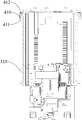
- Figure 4 is a partial enlarged view of Figure 3;
- FIG. 5 is a third schematic diagram of a motion state of an air outlet device according to an embodiment of the present invention.
- FIG. 6 is a schematic view of the assembly of the ejector air device according to an embodiment of the present invention.
- Figure 7 is a second schematic view of the assembly of the ejector air outlet according to the embodiment of the present invention.
- Figure 8 is a third schematic view of the assembly of the ejector air outlet according to the embodiment of the present invention.
- FIG. 9 is a schematic exploded view of an assembly of an ejector air outlet according to an embodiment of the present invention.
- the venting device provided by the invention can be applied to an air conditioner with an air outlet type, and in order to increase the air supply range of the air conditioner and improve the cooling comfort, the air outlet panel is usually set to be opposite to the air conditioner top.
- the structure of the lifting and lowering is provided with an air outlet on the air outlet panel.
- the air outlet panel rises a certain distance relative to the top cover, so that the air conditioner can supply air to the farther through the air outlet, when the air conditioner is not working,
- the air outlet panel is lowered relative to the top cover and can be housed inside the air conditioner after being placed.
- the invention is intended to solve the problem that when the air conditioner is not running, the air outlet panel is lowered in the process of closing the top cover of the air conditioner, and the movement stroke of the conventional air conditioner outlet panel is fixed, when the air outlet panel is lowered to the preset position and When the top cover is closed, due to deformation of the air outlet panel or the structure of the air conditioner top cover, the problem of gaps or uneven opening after closing causes not only the appearance of the air conditioner, but also external dust entering the interior of the air conditioner, affecting The normal operation of the air conditioner.
- an air outlet device includes a top cover assembly 100 , an exhaust air assembly 200 , a detection mechanism 300 , an adjustment mechanism 400 , and a controller .
- the top cover assembly 100 is mounted on the air conditioner.
- the top, ejector assembly 200 can be raised and lowered relative to the cap assembly 100 such that the vent of the ejector assembly 200 can be opened by the cap assembly 100 or closed by the cap assembly 100, in fact, the vent is opened or
- the closed state is also the open or closed state of the ejector assembly 200 relative to the cap assembly 100.
- the lifting movement of the top air outlet assembly 200 relative to the top cover assembly 100 is controlled by a controller.
- the controller controls the top air outlet assembly 200 to rise relative to the top cover assembly 100 to a preset position (working position).
- the air outlet is opened, the air conditioner is in the running air state; when the environment is not required to be air-conditioned, the controller controls the top air outlet assembly 200 to descend to the preset position (closed position) with respect to the top cover assembly 100. Continuing to descend, the air outlet is closed.
- the ejector assembly 200 should be tightly closed with the top cover assembly 100, and the distance between the working position and the closed position is the stroke required for the ejector assembly 200 to move.
- the adjustment mechanism 400 is for increasing the stroke within the range of its expansion and contraction, so that the ejector assembly 200 can continue to descend a distance after reaching the closed position to reduce the space between the ejector assembly 200 and the cover assembly 100.
- the gap distance further solves the problem of a gap between the top air outlet assembly 200 and the top cover assembly 100 when it reaches the closed position.
- the detecting mechanism 300 is configured to detect when the ejector component 200 reaches the closed position, and when detecting that the ejector component 200 reaches the closed position, sends a signal to the controller to enable the controller to control the ejector component 200 to continue.
- the distance is decreased after a certain distance, and the distance is determined by the expansion and contraction range of the adjustment mechanism 400. In fact, during the actual operation, it is only necessary to set a program for the controller to cause the controller to control the top air outlet assembly 200 to continue moving for a while and then stop.
- the adjusting mechanism 400 can be disposed on the top air outlet assembly 200 or the top cover assembly 100, and the detecting mechanism 300 is oppositely disposed on the top cover assembly 100 or the top air outlet assembly 200, and the two can cooperate with each other as long as they are ejected.
- the wind assembly 200 may have a state of being touchable during the lifting movement of the top cover assembly 100.
- the adjustment mechanism 400 includes a guide post 410 and an elastic connecting member 420; the top air outlet assembly 200 is provided with a mounting portion 210, the guiding post 410 is slidably disposed on the mounting portion 210; and the elastic connecting member 420 is disposed on the guiding portion The post 410 is between the mounting portion 210.
- the elastic connecting member 420 may be a spring or a spring piece or the like.
- the guide post 410 is mounted on the ejector air assembly 200 through the mounting portion 210 for contacting the detecting mechanism 300.
- the detection mechanism 300 includes a travel switch 310 that is secured to the top cover assembly 100.
- the travel switch 310 sends a signal to the controller to cause the top air outlet assembly 200 to continue to descend, the mounting portion 210
- the guide post 410 can slide relative to the mounting portion 210, the travel switch 310 and the guide post 410 interfere with each other but does not affect the ejecting wind assembly 200 to continue to descend, and the guide post 410 is lifted by the travel switch 310.
- the distance is such that the elastic connecting member 420 disposed between the guiding post 410 and the mounting portion 210 is compressed, the elastic connecting member 420 is compressed and deformed, and the maximum elastic deformation of the elastic connecting member 420 and the length of the guiding post 410 jointly determine the above.
- the telescopic range of the adjustment mechanism 400 is adjusted.
- the mounting portion 210 includes a fixing block 211; the fixing block 211 is provided with a through hole for penetrating the guiding post 410; the guiding post 410 has a first end 411 and a second end 412 through the first end 411 and the second end 412 sets the guide post 410 in a state of being restricted from coming out of the through hole.
- the resilient connector 420 is preferably a spring that is sleeved over the guide post 410 between the first end 411 and the fixed block 211, wherein the spring can be a coil spring, a compression spring, or the like.
- the first end 411 is the lower end of the guide post 410
- the second end 412 is the upper end of the guide post 410
- the ejector assembly 200 is lowered and the cap assembly 100 is closed.
- the lower end of the guide post 410 protrudes from the lower end surface of the fixed block by a length L1, assuming that the spring is in an unstressed state, and the ends of the spring are just opposite to the guide post 410 and The fixed block abuts; then the lower end of the guide post 410 touches the travel switch 310, and the spring is compressed, so that the lower end of the guide post 410 is shortened to L2 with respect to the lower end surface of the fixed block; and the controller controls the ejection
- the wind assembly 200 continues to descend, and the spring continues to be compressed, so that the length of the lower end of the guide post 410 relative to the lower end surface of the fixed block is shortened to L3. If the spring is already at its maximum deformation, the
- the adjusting mechanism 400 further includes a screw 430, and the screw 430 constitutes the second end 412.
- the guiding post 410 is provided with a screw hole that cooperates with the screw 430, and is fixed in the screw hole by the screw 430, so that the guiding post 410 and the fixing block can be conveniently.
- the installation and disassembly can change the length of the guide post 410 or replace the spring of different deformation degrees according to different stroke requirements, so as to achieve the purpose of adjusting different stroke ranges.
- the mounting portion 210 can be a slot, and one end of the guide post 410 is fixed in the slot through the elastic connecting member 420, and the other end is a free end, and can be extended or retracted relative to the slot.
- the detecting mechanism 300 may include a pressure sensor electrically connected to the controller, the top cover assembly 100 is provided with a bump for contacting the adjusting mechanism 400, and the pressure sensor is disposed at the bump and the adjusting mechanism 400. In the position of the touch, when the bump touches the adjustment mechanism 400, the pressure sensor generates a pressure signal and feeds back to the controller, and the controller controls the top air outlet mechanism to continue to move the preset distance.
- the ejector assembly 200 includes a support frame 220 and an adjustment mechanism. 400 is disposed on the support frame 220; the top cover assembly 100 includes a fixing frame 110, and the detecting mechanism 300 is disposed on the fixing frame 110. Further, the ejector assembly 200 further includes an air outlet panel 230.
- the top cover assembly 100 further includes a sealing cover 120.
- the sealing cover 120 has a ring shape, and the air outlet panel 230 has a cylindrical shape.
- the sealing cover 120 is configured to be sleeved on the air outlet panel. When the air outlet of the top air outlet assembly 200 is closed by the top cover assembly 100, the edge of the upper end surface of the air outlet panel 230 and the upper edge of the sealing cover 120 can be closely closed.
- the upper end surface of the air outlet panel 230 has an arc shape, and the distance from the edge of the upper end surface of the air outlet panel 230 to the top cover assembly 100 has a state of being changed from low to high.
- the side wall side of the air outlet panel 230 is low on one side, and the upper end surface is convexly curved to cover the upper edge of the side wall, and the outer shape of the sealing cover 120 is adapted to the outer shape of the air outlet panel 230.
- the upper edge of the sealing cover 120 has a bell mouth shape, and the upper end side wall of the air outlet panel 230 can be fitted with the upper edge of the sealing cover 120, thereby increasing the contact area when the two are closed, so that the closing is performed. More closely.
- the air outlet panel 230 is fixed on the support frame 220 , and the sealing cover 120 is fixed on the top cover assembly 100 , and the support frame 220 can be lifted and lowered relative to the fixed frame 110 , so that the air outlet panel 230 can
- the up and down movement relative to the seal cover 120 is such that the wind exit panel 230 has an open and closed state relative to the seal cover 120.
- the air conditioner is ventilated by the air outlet on the air outlet panel 230; when the air outlet panel 230 is lowered to the closed position, as shown in FIG. 7, the air is discharged at this time.
- the air outlet panel 230 Under the cooperation of the adjusting mechanism 400 and the detecting mechanism 300, the air outlet panel 230 can continue to descend a distance, as shown in FIG. 8, at this time, the air outlet panel 230 and the sealing cover 120. Closed tightly and seamlessly.
- the venting device further includes a power source and a transmission mechanism, and the power source is electrically connected to the controller; the power source is disposed on the top cover assembly 100, and the power source drives the ejector assembly 200 through the transmission mechanism.
- the top cover assembly 100 moves.
- the power source may be a motor or the like, and the controller controls the movement or stop of the ejector assembly 200 relative to the cap assembly 100 by controlling the operation or stop of the motor.
- the transmission mechanism includes a gear and a rack, the gear is disposed on the output shaft of the motor, and the rack is disposed on the top air outlet assembly 200, and the motor drives the gear to reciprocate to drive the rack to reciprocate, thereby causing the top air outlet assembly 200
- the lifting movement can be performed relative to the top cover assembly 100.
- the embodiment of the invention further provides an air conditioner, comprising the air outlet device as described above, so that the air outlet panel and the top cover of the air conditioner can be closed tightly, not only having good appearance, but also preventing dust and the like from entering the air conditioner. .
- Another embodiment of the present invention further provides a motion control method for an air outlet device, wherein the air outlet device is the above-described air outlet device; and the control method includes: the controller controls the air outlet component relative to the top cover The component moves up and down; when the adjusting mechanism touches the detecting mechanism, the controller controls the top air outlet component to continue to move within the elastic expansion and contraction range of the adjusting mechanism, thereby enabling automatic control of the movement of the top air outlet component relative to the top cover component, so that The top air outlet assembly can be completely closed with the top cover assembly to ensure the sealing of the air outlet.
- a program can be set by the controller.
- the controller controls the top air outlet component to continue to move for a preset time within the elastic stretching range of the adjusting mechanism, and the preset time is about 1 to 2 seconds.
Landscapes
- Engineering & Computer Science (AREA)
- Chemical & Material Sciences (AREA)
- Combustion & Propulsion (AREA)
- Mechanical Engineering (AREA)
- General Engineering & Computer Science (AREA)
- Life Sciences & Earth Sciences (AREA)
- Atmospheric Sciences (AREA)
- Air-Flow Control Members (AREA)
- Jet Pumps And Other Pumps (AREA)
Abstract
一种顶出风装置,包括:顶盖组件(100)、顶出风组件(200)、检测机构(300)、调节机构(400)和控制器;顶出风组件(200)能够相对于顶盖组件(100)升降,控制器用于控制两者的升降运动;调节机构(400)、检测机构(300)分别设置在顶出风组件(200)和顶盖组件(100)上,调节机构(400)具有伸缩弹性;在顶出风组件(200)相对于顶盖组件(100)升降运动的过程中,当调节机构(400)触碰到检测机构(300)时,检测机构(300)向控制器发出检测信号,使控制器控制顶出风组件(200)在调节机构(400)的弹性伸缩范围内继续运动;顶出风装置通过调节机构(400)在其伸缩范围内增加了顶出风组件(200)的运动行程,从而使得顶出风组件(200)能够与顶盖组件(100)完全闭合;还包括一种空调器,以及一种顶出风装置的运动控制方法。
Description
相关申请
本申请要求2017年01月11日申请的,申请号为201710018070.3,名称为“顶出风装置、空调器及顶出风装置的运动控制方法”的中国专利申请的优先权,在此将其全文引入作为参考。
本发明涉及空调设备技术领域,特别是涉及一种顶出风装置及具有其的空调器,以及一种顶出风装置的运动控制方法。
目前,有部分柜式空调器采用顶出风的方式,即在空调顶盖处设置一个出风面板,由空调顶部向外出风。为了增大空调器的送风范围,提高制冷舒适性,通常会将出风面板设置为可相对于空调器顶盖升降的结构,从而使得空调器在工作过程中,出风面板能够相对于顶盖上升一定距离,使空调器能够向较远处送风,在空调不工作时,出风面板相对于顶盖下降,到位后能够收容于空调器内部。
但是,传统的顶出风式空调器,出风面板下降在与空调器顶盖闭合的过程中,出风面板的运动行程是固定的,当出风面板下降至预设位置与顶盖闭合时,由于出风面板或者空调器顶盖结构变形等原因,闭合之后易出现缝隙或者闭合不均匀的问题,不仅影响空调器的外观,还会导致外界灰尘等进入空调器内部,影响空调器的正常运行。
发明内容
基于此,有必要针对传统出风面板与顶盖易出现闭合不严、具有缝隙等问题,提供一种闭合紧密的顶出风装置,同时还提供了一种包含该顶出风装置的空调器,以及一种顶出风装置的运动控制方法。
上述目的通过以下技术方案实现:
一种顶出风装置,包括顶盖组件、顶出风组件、检测机构、调节机构和控制器;
顶出风组件能够相对于顶盖组件升降,从而使顶出风组件的出风口能够被顶盖组件打开或者关闭;控制器用于控制顶出风组件相对于顶盖组件的升降运动;
调节机构设置在顶出风组件或顶盖组件的一者上,检测机构设置在顶出风组件或顶盖组件的另一者上,顶出风组件相对于顶盖组件升降运动时,调节机构与检测机构能够相互靠近
或者远离;调节机构具有伸缩弹性;在顶出风组件相对于顶盖组件升降运动的过程中,当调节机构触碰到检测机构时,检测机构向控制器发出检测信号,使控制器控制顶出风组件在调节机构的弹性伸缩范围内继续运动。
在其中一个实施例中,调节机构包括导柱和弹性连接件;顶出风组件上设置有安装部,导柱滑设于安装部;弹性连接件设置在导柱与安装部之间。
在其中一个实施例中,安装部包括固定块;固定块上设置有用于穿设导柱的通孔;导柱具有第一端和第二端,通过第一端和第二端使导柱以被限制从通孔中脱出的状态设置。
在其中一个实施例中,弹性连接件为弹簧,弹簧套设在第一端与固定块之间的导柱上。
在其中一个实施例中,调节机构还包括螺钉,螺钉用于形成第二端;导柱开设有与螺钉配合的螺孔。
在其中一个实施例中,检测机构包括行程开关,行程开关固定在顶盖组件上,当行程开关与第一端触碰时,行程开关向控制器发出检测信号,使控制器控制顶出风组件继续运动预设距离。
在其中一个实施例中,顶出风组件包括支撑架,调节机构设置在支撑架上;顶盖组件包括固定架,检测机构设置在固定架上。
一种空调器,包括如上任一项所述的顶出风装置。
一种顶出风装置的运动控制方法,其中,顶出风装置为上述任一项所述的顶出风装置;控制方法包括以下步骤:
控制器控制顶出风组件相对于顶盖组件升降运动;
当调节机构触碰到检测机构时,控制器控制顶出风组件在调节机构的弹性伸缩范围内继续运动。
在其中一个实施例中,当调节机构触碰到检测机构时,控制器控制顶出风组件在调节机构的弹性伸缩范围内继续运动预设时间。
上述顶出风装置,其通过调节机构调整顶出风组件相对于顶盖组件运动的行程,并通过检测机构能够判断出调节机构调整行程的初始位置,以便通过控制器控制顶出风组件相对于顶盖组件继续运动的距离范围。传统的顶出风装置,顶出风组件在运动了固定行程后就不能继续运动了,此时顶出风组件与顶盖组件可能由于产品变形等原因不能够完全闭合,而本发明的顶出风装置通过调节机构在其伸缩范围内增加了顶出风组件的运动行程,从而使得顶出风组件能够与顶盖组件完全闭合,保证出风口的密封。
由于顶出风装置具有上述有益效果,包含该顶出风装置的空调器也具有相应的有益效果。
上述顶出风装置的运动控制方法,能够实现顶出风组件相对于顶盖组件运动的自动控制,使得顶出风组件能够与顶盖组件完全闭合,保证出风口的密封。
图1为本发明实施例提供的顶出风装置的结构示意图;
图2为本发明实施例提供的顶出风装置的运动状态示意图一;
图3为本发明实施例提供的顶出风装置的运动状态示意图二;
图4为图3的局部放大图;
图5为本发明实施例提供的顶出风装置的运动状态示意图三;
图6为本发明实施例提供的顶出风装置的装配示意图一;
图7为本发明实施例提供的顶出风装置的装配示意图二;
图8为本发明实施例提供的顶出风装置的装配示意图三;
图9为本发明实施例提供的顶出风装置的装配爆炸示意图。
其中:
100-顶盖组件;
110-固定架;
120-密封罩;
200-顶出风组件;
210-安装部;211-固定块;
220-支撑架;
230-出风面板;
300-检测机构;
310-行程开关;
400-调节机构;
410-导柱;411-第一端;412-第二端;
420-弹性连接件;430-螺钉。
为了使本发明的目的、技术方案及优点更加清楚明白,以下通过实施例,并结合附图,对本发明的顶出风装置、空调器及顶出风装置的运动控制方法进行进一步详细说明。应当理解,此处所描述的具体实施例仅用以解释本发明,并不用于限定本发明。
需要说明的是,当元件被称为“固定于”另一个元件,它可以直接在另一个元件上或者也可以存在居中的元件。当一个元件被认为是“连接”另一个元件,它可以是直接连接到另一个元件或者可能同时存在居中元件。相反,当元件被称作“直接在”另一元件“上”时,不存在中间元件。本文所使用的术语“垂直的”、“水平的”、“左”、“右”以及类似的表述只
是为了说明的目的。
本发明提供的顶出风装置,可应用于顶出风方式的空调器,而为了增大空调器的送风范围,提高制冷舒适性,通常会将出风面板设置为可相对于空调器顶盖升降的结构,出风面板上设有出风口,空调工作过程中,出风面板相对于顶盖上升一定距离,使空调器能够通过出风口向较远处送风,在空调不工作时,出风面板相对于顶盖下降,到位后能够收容于空调器内部。本发明意在解决空调器不运行时,出风面板下降在与空调器顶盖闭合的过程中,传统的空调器出风面板的运动行程是固定的,当出风面板下降至预设位置与顶盖闭合时,由于出风面板或者空调器顶盖结构变形等原因,导致闭合之后出现缝隙或者闭合不均匀的问题,不仅影响空调器的外观,还会导致外界灰尘等进入空调器内部,影响空调器的正常运行。
如图1所示,本发明一实施例的顶出风装置,包括顶盖组件100、顶出风组件200、检测机构300、调节机构400和控制器,顶盖组件100用于安装在空调器顶部,顶出风组件200能够相对于顶盖组件100升降,从而使顶出风组件200的出风口能够被顶盖组件100打开,或者被顶盖组件100关闭,事实上,出风口被打开或者关闭的状态也就是顶出风组件200相对于顶盖组件100的开启或者闭合状态。顶出风组件200相对于顶盖组件100的升降运动由控制器来控制,正常状况下,控制器控制顶出风组件200相对于顶盖组件100上升至预设位置(工作位)后不再继续上升,出风口被打开空调器处于运行出风状态;不需要对环境进行空气调节时,控制器控制顶出风组件200相对于顶盖组件100下降至预设位置(闭合位)后不再继续下降,出风口被关闭,此时,理论上顶出风组件200应该与顶盖组件100能够紧密闭合,工作位与闭合位之间的距离为顶出风组件200运动所需的行程。
而调节机构400则是用于在其伸缩的范围内增加上述行程,使得顶出风组件200能够在到达闭合位后继续下降一段距离,以缩小顶出风组件200与顶盖组件100之间的间隙距离,进而解决顶出风组件200到达闭合位时与顶盖组件100之间存在缝隙等问题。进一步地,检测机构300用于检测顶出风组件200何时到达闭合位,并在检测到顶出风组件200到达闭合位时,向控制器发出信号,使控制器能够控制顶出风组件200继续下降一段距离后再停止,而该一段距离由调节机构400的伸缩范围来决定。事实上,在实际操作过程中,仅需要给控制器设定一个程序,使控制器控制顶出风组件200继续运动一段时间后停止。
其中,调节机构400可以设置在顶出风组件200或者顶盖组件100上,而检测机构300相对地设置在顶盖组件100或者顶出风组件200上,两者能够相互配合,只要在顶出风组件200相对于顶盖组件100升降运动的过程中具有能够触碰的状态即可。
作为一种优选的实施方式,调节机构400包括导柱410和弹性连接件420;顶出风组件200上设置有安装部210,导柱410滑设于安装部210;弹性连接件420设置在导柱410与安装部210之间。
其中,弹性连接件420可以是弹簧或者弹片等。导柱410通过安装部210安装在顶出风组件200上,导柱410用于与检测机构300触碰。优选地,检测机构300包括行程开关310,行程开关310固定在顶盖组件100上。在顶出风组件200下降与顶盖组件100闭合的过程中,当导柱410触碰到行程开关310时,行程开关310向控制器发出信号,使顶出风组件200继续下降,安装部210也会随之下降,由于导柱410能够相对于安装部210滑动,行程开关310与导柱410相互抵触但并不影响顶出风组件200继续下降,并且导柱410被行程开关310顶起一段距离,使得设置在导柱410与安装部210之间的弹性连接件420被压缩,弹性连接件420被压缩发生形变,弹性连接件420的最大弹性形变量和导柱410的长度共同决定了上述调节机构400的可伸缩范围。
具体的,安装部210包括固定块211;固定块211上设置有用于穿设导柱410的通孔;导柱410具有第一端411和第二端412,通过第一端411和第二端412使导柱410以被限制从通孔中脱出的状态设置。弹性连接件420优选地为弹簧,弹簧套设在第一端411与固定块211之间的导柱410上,其中弹簧可以是螺旋弹簧、压缩弹簧等。
参见图2至图5,从图示方向来看,第一端411为导柱410的下端,第二端412为导柱410的上端,顶出风组件200下降与顶盖组件100闭合的过程中,初始时导柱410在弹簧的作用下,其下端相对于固定块的下端面伸出长度为L1,假设此时弹簧处于未受力的状态,且弹簧两端刚好分别与导柱410和固定块抵接;接着导柱410的下端触碰到行程开关310,瞬间弹簧受到压缩,使导柱410的下端相对于固定块的下端面伸出长度缩短至L2;同时控制器会控制顶出风组件200继续下降,弹簧持续受到压缩,使导柱410下端相对于固定块的下端面伸出长度缩短为L3,假设此时弹簧已经处于其最大形变了,则调节机构400可调整的行程范围为0~L,其中L=L1﹣L3。
进一步地,调节机构400还包括螺钉430,螺钉430构成上述第二端412,导柱410开设有与螺钉430配合的螺孔,通过螺钉430固定在螺孔内,能够方便导柱410与固定块的安装和拆卸,从而能够根据不同行程需求更换导柱410的长度或者更换不同形变程度的弹簧,以达到调整不同行程范围的目的。
在其他实施例中,安装部210可以是槽孔,导柱410的一端通过弹性连接件420固定槽孔中,另一端为自由端,可相对于槽孔伸出或者缩进。
在其他实施例中,检测机构300可以包括压力传感器,压力传感器与控制器电连接,顶盖组件100设置有用于与调节机构400触碰的凸块,压力传感器设置在凸块与调节机构400触碰的位置,当凸块与调节机构400发生触碰时,压力传感器出现压力信号并反馈给控制器,则控制器控制顶出风机构继续运动预设距离。
参见图1和图9,作为一种优选的实施方式,顶出风组件200包括支撑架220,调节机构
400设置在支撑架220上;顶盖组件100包括固定架110,检测机构300设置在固定架110上。进一步地,顶出风组件200还包括出风面板230,顶盖组件100还包括密封罩120;密封罩120呈环形,出风面板230呈柱形,密封罩120用于套设在出风面板230外;当顶出风组件200的出风口被顶盖组件100关闭时,出风面板230的上端面的边沿与密封罩120的上边沿能够贴紧闭合。
其中,出风面板230的上端面呈弧形,且出风面板230的上端面的边沿到顶盖组件100的距离具有由低到高的变化状态。参见图9,出风面板230的侧壁一侧低一侧高,上端面呈凸弧形覆盖侧壁上边沿,而密封罩120的外形与出风面板230外形适配。
参见图6,进一步地,密封罩120的上边沿呈喇叭口状,出风面板230的上端侧壁能够与密封罩120的上边沿适配,从而增加了两者闭合时的接触面积,使得闭合更加紧密。
参见图6至图8,具体地,出风面板230固定在支撑架220上,密封罩120固定在顶盖组件100上,通过支撑架220能够相对于固定架110升降,使得出风面板230能够相对于密封罩120上下移动,从而使得出风面板230相对于密封罩120具有开启和闭合的状态。出风面板230上升至工作位时,如图6所示,空调器由出风面板230上的出风口出风;出风面板230下降至闭合位时,如图7所示,此时出风面板230与密封罩120之间具有缝隙;在调节机构400与检测机构300的配合作用下,出风面板230能够继续下降一段距离,如图8所示,此时出风面板230与密封罩120闭合紧密无缝隙。
作为一种优选的实施方式,顶出风装置还包括动力源和传动机构,动力源与控制器电连接;动力源设置在顶盖组件100上,动力源通过传动机构带动顶出风组件200相对顶盖组件100运动。
动力源可以是电机等,控制器通过控制电机的运转或停止来控制顶出风组件200相对于顶盖组件100运动或停止。
具体的,传动机构包括齿轮和齿条,齿轮设置在电机的输出轴上,齿条设置在顶出风组件200上,电机带动齿轮往复转动进而带动齿条往复运动,从而使得顶出风组件200能够相对于顶盖组件100做升降运动。
本发明实施例还提供了一种空调器,包括如上所述的顶出风装置,从而该空调器的出风面板与顶盖能够闭合紧密,不仅外观良好,而且能够防止灰尘等进入空调器内部。
本发明的另一实施例还提供了一种顶出风装置的运动控制方法,其中,顶出风装置为上述的顶出风装置;控制方法包括:控制器控制顶出风组件相对于顶盖组件升降运动;当调节机构触碰到检测机构时,控制器控制顶出风组件在调节机构的弹性伸缩范围内继续运动,从而能够实现顶出风组件相对于顶盖组件运动的自动控制,使得顶出风组件能够与顶盖组件完全闭合,保证出风口的密封,具体的,实际操作过程中,可以通过给控制器设定一个程序,
当调节机构触碰到检测机构时,控制器控制顶出风组件在调节机构的弹性伸缩范围内继续运动预设时间,该预设时间大约为1~2秒即可。
以上所述实施例的各技术特征可以进行任意的组合,为使描述简洁,未对上述实施例中的各个技术特征所有可能的组合都进行描述,然而,只要这些技术特征的组合不存在矛盾,都应当认为是本说明书记载的范围。
以上所述实施例仅表达了本发明的几种实施方式,其描述较为具体和详细,但并不能因此而理解为对发明专利范围的限制。应当指出的是,对于本领域的普通技术人员来说,在不脱离本发明构思的前提下,还可以做出若干变形和改进,这些都属于本发明的保护范围。因此,本发明专利的保护范围应以所附权利要求为准。
Claims (10)
- 一种顶出风装置,其特征在于,包括顶盖组件(100)、顶出风组件(200)、检测机构(300)、调节机构(400)和控制器;所述顶出风组件(200)能够相对于所述顶盖组件(100)升降,从而使所述顶出风组件(200)的出风口能够被所述顶盖组件(100)打开或关闭;所述控制器用于控制所述顶出风组件(200)相对于所述顶盖组件(100)的升降运动;所述调节机构(400)设置在所述顶出风组件(200)或所述顶盖组件(100)的一者上,所述检测机构(300)设置在所述顶出风组件(200)或所述顶盖组件(100)的另一者上,所述顶出风组件(200)相对于所述顶盖组件(100)升降运动时,所述调节机构(400)与所述检测机构(300)能够相互靠近或者远离;所述调节机构(400)具有伸缩弹性;在所述顶出风组件(200)相对于所述顶盖组件(100)升降运动的过程中,当所述调节机构(400)触碰到所述检测机构(300)时,所述检测机构(300)向所述控制器发出检测信号,使所述控制器控制所述顶出风组件(200)在所述调节机构(400)的弹性伸缩范围内继续运动。
- 根据权利要求1所述的顶出风装置,其特征在于,所述调节机构(400)包括导柱(410)和弹性连接件(420);所述顶出风组件(200)上设置有安装部(210),所述导柱(410)滑设于所述安装部(210);所述弹性连接件(420)设置在所述导柱(410)与所述安装部(210)之间。
- 根据权利要求2所述的顶出风装置,其特征在于,所述安装部(210)包括固定块(211);所述固定块(211)上设置有用于穿设所述导柱(410)的通孔;所述导柱(410)具有第一端(411)和第二端(412),通过所述第一端(411)和所述第二端(412)使所述导柱(410)以被限制从所述通孔中脱出的状态设置。
- 根据权利要求3所述的顶出风装置,其特征在于,所述弹性连接件(420)为弹簧,所述弹簧套设在所述第一端(411)与所述固定块(211)之间的所述导柱(410)上。
- 根据权利要求3所述的顶出风装置,其特征在于,所述调节机构(400)还包括螺钉(430),所述螺钉(430)用于形成所述第二端(412);所述导柱(410)开设有与所述螺钉(430)配合的螺孔。
- 根据权利要求3所述的顶出风装置,其特征在于,所述检测机构(300)包括行程开关(310),所述行程开关(310)固定在所述顶盖组件(100)上,当所述行程开关(310)与所述导柱的第一端(411)触碰时,所述行程开关(310)向所述控制器发出检测信号,使所述控制器控制所述顶出风组件(200)继续运动预设距离。
- 根据权利要求1-6任一项所述的顶出风装置,其特征在于,所述顶出风组件(200) 包括支撑架(220),所述调节机构(400)设置在所述支撑架(220)上;所述顶盖组件(100)包括固定架(110),所述检测机构(300)设置在所述固定架(110)上。
- 一种空调器,其特征在于,包括如权利要求1-7任一项所述的顶出风装置。
- 一种顶出风装置的运动控制方法,其特征在于,顶出风装置为权利要求1-7任一项所述的顶出风装置;所述控制方法包括以下步骤:控制器控制顶出风组件相对于顶盖组件升降运动;当调节机构触碰到检测机构时,控制器控制顶出风组件在调节机构的弹性伸缩范围内继续运动。
- 根据权利要求9所述的顶出风装置的运动控制方法,其特征在于,当调节机构触碰到检测机构时,控制器控制顶出风组件在调节机构的弹性伸缩范围内继续运动预设时间。
Priority Applications (1)
| Application Number | Priority Date | Filing Date | Title |
|---|---|---|---|
| EP17891185.5A EP3569946B1 (en) | 2017-01-11 | 2017-10-19 | Top air-outlet device, air conditioner, and motion control method of the top air-outlet device |
Applications Claiming Priority (2)
| Application Number | Priority Date | Filing Date | Title |
|---|---|---|---|
| CN201710018070.3 | 2017-01-11 | ||
| CN201710018070.3A CN106642618B (zh) | 2017-01-11 | 2017-01-11 | 顶出风装置、空调器及顶出风装置的运动控制方法 |
Publications (1)
| Publication Number | Publication Date |
|---|---|
| WO2018129974A1 true WO2018129974A1 (zh) | 2018-07-19 |
Family
ID=58843640
Family Applications (1)
| Application Number | Title | Priority Date | Filing Date |
|---|---|---|---|
| PCT/CN2017/106877 Ceased WO2018129974A1 (zh) | 2017-01-11 | 2017-10-19 | 顶出风装置、空调器及顶出风装置的运动控制方法 |
Country Status (3)
| Country | Link |
|---|---|
| EP (1) | EP3569946B1 (zh) |
| CN (1) | CN106642618B (zh) |
| WO (1) | WO2018129974A1 (zh) |
Cited By (2)
| Publication number | Priority date | Publication date | Assignee | Title |
|---|---|---|---|---|
| CN115077080A (zh) * | 2022-05-09 | 2022-09-20 | 青岛海尔空调器有限总公司 | 用于带动导风板运动的驱动机构和空调器 |
| US20240271821A1 (en) * | 2022-12-30 | 2024-08-15 | Soto Air Purification Technology (langfang) Co., Ltd. | Air disinfector |
Families Citing this family (7)
| Publication number | Priority date | Publication date | Assignee | Title |
|---|---|---|---|---|
| CN106642618B (zh) * | 2017-01-11 | 2022-04-29 | 珠海格力电器股份有限公司 | 顶出风装置、空调器及顶出风装置的运动控制方法 |
| EP3730850A1 (en) * | 2019-03-06 | 2020-10-28 | GD Midea Air-Conditioning Equipment Co., Ltd. | Air conditioner indoor unit |
| CN110925930B (zh) * | 2019-11-22 | 2021-06-04 | 深圳市盛仕达电子有限公司 | 一种具有降噪功能的防尘型新风机 |
| CN112050317A (zh) * | 2020-09-14 | 2020-12-08 | 卞毓平 | 一种用于智能家居的空气净化装置 |
| KR102940482B1 (ko) * | 2020-12-30 | 2026-03-17 | 엘지전자 주식회사 | 공기조화기 |
| CN115077077B (zh) * | 2022-05-09 | 2025-12-19 | 青岛海尔空调器有限总公司 | 摇杆滑块换向空调及其导风板 |
| CN115682269B (zh) * | 2022-12-30 | 2023-04-14 | 赛多空气净化技术(廊坊)有限公司 | 一种空气消毒机 |
Citations (5)
| Publication number | Priority date | Publication date | Assignee | Title |
|---|---|---|---|---|
| KR20090116522A (ko) * | 2008-05-07 | 2009-11-11 | 삼성전자주식회사 | 스탠드형 공기조화기 |
| US20160327297A1 (en) * | 2015-05-07 | 2016-11-10 | Samsung Electronics Co., Ltd. | Air conditioner and method for controlling the same |
| CN106225080A (zh) * | 2016-08-31 | 2016-12-14 | 芜湖美智空调设备有限公司 | 空调柜机和空调柜机的出风控制方法 |
| CN106642618A (zh) * | 2017-01-11 | 2017-05-10 | 珠海格力电器股份有限公司 | 顶出风装置、空调器及顶出风装置的运动控制方法 |
| CN206449815U (zh) * | 2017-01-11 | 2017-08-29 | 珠海格力电器股份有限公司 | 顶出风装置及具有其的空调器 |
Family Cites Families (9)
| Publication number | Priority date | Publication date | Assignee | Title |
|---|---|---|---|---|
| JP3392644B2 (ja) * | 1996-06-26 | 2003-03-31 | 東芝キヤリア株式会社 | 空気調和装置の室内機 |
| KR100758958B1 (ko) * | 2006-02-14 | 2007-09-14 | 엘지전자 주식회사 | 공기조화기의 실내기 |
| KR101403002B1 (ko) * | 2007-10-29 | 2014-06-20 | 엘지전자 주식회사 | 공기조화기 |
| CN203362551U (zh) * | 2012-05-24 | 2013-12-25 | 夏普株式会社 | 送风装置和带电粒子输出装置 |
| CN104566671B (zh) * | 2014-12-31 | 2017-06-09 | 广东美的制冷设备有限公司 | 顶部出风的空气净化器 |
| CN105135652B (zh) * | 2015-09-11 | 2019-05-07 | 珠海格力电器股份有限公司 | 空气调节装置顶盖组件及空气调节装置 |
| CN105222308B (zh) * | 2015-09-11 | 2018-06-29 | 珠海格力电器股份有限公司 | 空气调节装置顶盖组件及空气调节装置 |
| CN105115134B (zh) * | 2015-09-11 | 2018-10-19 | 珠海格力电器股份有限公司 | 空气调节装置顶盖组件及空气调节装置 |
| CN106287973B (zh) * | 2016-08-31 | 2019-08-16 | 芜湖美智空调设备有限公司 | 空调柜机和空调柜机的出风控制方法 |
-
2017
- 2017-01-11 CN CN201710018070.3A patent/CN106642618B/zh active Active
- 2017-10-19 EP EP17891185.5A patent/EP3569946B1/en active Active
- 2017-10-19 WO PCT/CN2017/106877 patent/WO2018129974A1/zh not_active Ceased
Patent Citations (5)
| Publication number | Priority date | Publication date | Assignee | Title |
|---|---|---|---|---|
| KR20090116522A (ko) * | 2008-05-07 | 2009-11-11 | 삼성전자주식회사 | 스탠드형 공기조화기 |
| US20160327297A1 (en) * | 2015-05-07 | 2016-11-10 | Samsung Electronics Co., Ltd. | Air conditioner and method for controlling the same |
| CN106225080A (zh) * | 2016-08-31 | 2016-12-14 | 芜湖美智空调设备有限公司 | 空调柜机和空调柜机的出风控制方法 |
| CN106642618A (zh) * | 2017-01-11 | 2017-05-10 | 珠海格力电器股份有限公司 | 顶出风装置、空调器及顶出风装置的运动控制方法 |
| CN206449815U (zh) * | 2017-01-11 | 2017-08-29 | 珠海格力电器股份有限公司 | 顶出风装置及具有其的空调器 |
Non-Patent Citations (1)
| Title |
|---|
| See also references of EP3569946A4 * |
Cited By (3)
| Publication number | Priority date | Publication date | Assignee | Title |
|---|---|---|---|---|
| CN115077080A (zh) * | 2022-05-09 | 2022-09-20 | 青岛海尔空调器有限总公司 | 用于带动导风板运动的驱动机构和空调器 |
| US20240271821A1 (en) * | 2022-12-30 | 2024-08-15 | Soto Air Purification Technology (langfang) Co., Ltd. | Air disinfector |
| US12203676B2 (en) * | 2022-12-30 | 2025-01-21 | SOTO Air Purification Technology (Langfang) Co. , Ltd. | Air disinfector |
Also Published As
| Publication number | Publication date |
|---|---|
| EP3569946A4 (en) | 2020-01-08 |
| CN106642618B (zh) | 2022-04-29 |
| CN106642618A (zh) | 2017-05-10 |
| EP3569946A1 (en) | 2019-11-20 |
| EP3569946B1 (en) | 2023-06-14 |
Similar Documents
| Publication | Publication Date | Title |
|---|---|---|
| WO2018129974A1 (zh) | 顶出风装置、空调器及顶出风装置的运动控制方法 | |
| US11067292B2 (en) | Intelligent range hood and control method therefor | |
| KR102013833B1 (ko) | 공기 조화 장치용 헤드 커버 조립체 및 공기 조화 장치 | |
| CN206330188U (zh) | 一种智能吸油烟机 | |
| US12117185B2 (en) | Auxiliary mounting device and mounting and use method for saddle window air conditioner | |
| CN108253478B (zh) | 一种吸油烟机的活动部件升降机构及应用有该升降机构的吸油烟机 | |
| CN204084627U (zh) | 落地式空调器 | |
| CN114251726B (zh) | 一种空调的前面板控制方法及前面板装置 | |
| CN206449815U (zh) | 顶出风装置及具有其的空调器 | |
| WO2018145484A1 (zh) | 室内机及空调器 | |
| CN108620751A (zh) | 气悬浮装置及使用该气悬浮装置的激光切割机构 | |
| CN207214790U (zh) | 一种锂离子电池高真空烘箱密封门机构 | |
| CN205394142U (zh) | 一种机床移门用卡顿机构 | |
| CN104006167A (zh) | 用于工业窑炉的高温排气阀 | |
| CN206757288U (zh) | 一种自动投影幕 | |
| JP2024542636A5 (zh) | ||
| WO2023082630A1 (zh) | 一种导风板与面板之间间隙的控制方法及组件 | |
| KR101693891B1 (ko) | 도어 글래스 열림량 자동 조절장치 | |
| KR20230000439U (ko) | 창문 자동 개폐장치 | |
| CN210715218U (zh) | 风扇罩组件及机箱 | |
| CN210598553U (zh) | 一种新型地铁车辆折页门用止挡装置 | |
| CN214664796U (zh) | 一种空调室内机的面板驱动机构和空调室内机 | |
| CN209866924U (zh) | 升降式吸尘罩装置 | |
| CN220554843U (zh) | 一种通风柜视窗限位结构 | |
| CN218349715U (zh) | 一种防火阀密封性检测设备 |
Legal Events
| Date | Code | Title | Description |
|---|---|---|---|
| 121 | Ep: the epo has been informed by wipo that ep was designated in this application |
Ref document number: 17891185 Country of ref document: EP Kind code of ref document: A1 |
|
| NENP | Non-entry into the national phase |
Ref country code: DE |
|
| ENP | Entry into the national phase |
Ref document number: 2017891185 Country of ref document: EP Effective date: 20190812 |