WO2018130029A1 - 用于神经网络计算的计算设备和计算方法 - Google Patents
用于神经网络计算的计算设备和计算方法 Download PDFInfo
- Publication number
- WO2018130029A1 WO2018130029A1 PCT/CN2017/115038 CN2017115038W WO2018130029A1 WO 2018130029 A1 WO2018130029 A1 WO 2018130029A1 CN 2017115038 W CN2017115038 W CN 2017115038W WO 2018130029 A1 WO2018130029 A1 WO 2018130029A1
- Authority
- WO
- WIPO (PCT)
- Prior art keywords
- matrix
- neural network
- unit
- data element
- line buffer
- Prior art date
- Legal status (The legal status is an assumption and is not a legal conclusion. Google has not performed a legal analysis and makes no representation as to the accuracy of the status listed.)
- Ceased
Links
Images




Classifications
-
- G—PHYSICS
- G05—CONTROLLING; REGULATING
- G05B—CONTROL OR REGULATING SYSTEMS IN GENERAL; FUNCTIONAL ELEMENTS OF SUCH SYSTEMS; MONITORING OR TESTING ARRANGEMENTS FOR SUCH SYSTEMS OR ELEMENTS
- G05B13/00—Adaptive control systems, i.e. systems automatically adjusting themselves to have a performance which is optimum according to some preassigned criterion
- G05B13/02—Adaptive control systems, i.e. systems automatically adjusting themselves to have a performance which is optimum according to some preassigned criterion electric
- G05B13/0265—Adaptive control systems, i.e. systems automatically adjusting themselves to have a performance which is optimum according to some preassigned criterion electric the criterion being a learning criterion
- G05B13/027—Adaptive control systems, i.e. systems automatically adjusting themselves to have a performance which is optimum according to some preassigned criterion electric the criterion being a learning criterion using neural networks only
-
- G—PHYSICS
- G06—COMPUTING OR CALCULATING; COUNTING
- G06N—COMPUTING ARRANGEMENTS BASED ON SPECIFIC COMPUTATIONAL MODELS
- G06N20/00—Machine learning
- G06N20/10—Machine learning using kernel methods, e.g. support vector machines [SVM]
-
- G—PHYSICS
- G06—COMPUTING OR CALCULATING; COUNTING
- G06N—COMPUTING ARRANGEMENTS BASED ON SPECIFIC COMPUTATIONAL MODELS
- G06N3/00—Computing arrangements based on biological models
- G06N3/02—Neural networks
- G06N3/04—Architecture, e.g. interconnection topology
- G06N3/0464—Convolutional networks [CNN, ConvNet]
-
- G—PHYSICS
- G06—COMPUTING OR CALCULATING; COUNTING
- G06N—COMPUTING ARRANGEMENTS BASED ON SPECIFIC COMPUTATIONAL MODELS
- G06N3/00—Computing arrangements based on biological models
- G06N3/02—Neural networks
- G06N3/06—Physical realisation, i.e. hardware implementation of neural networks, neurons or parts of neurons
- G06N3/063—Physical realisation, i.e. hardware implementation of neural networks, neurons or parts of neurons using electronic means
-
- G—PHYSICS
- G06—COMPUTING OR CALCULATING; COUNTING
- G06N—COMPUTING ARRANGEMENTS BASED ON SPECIFIC COMPUTATIONAL MODELS
- G06N3/00—Computing arrangements based on biological models
- G06N3/02—Neural networks
- G06N3/08—Learning methods
Definitions
- the present application relates to the field of data processing and, more particularly, to a computing device and a computing method for neural network computing.
- Neural networks (such as deep neural networks) are widely used in computer vision, natural language processing, and big data mining. Neural network computing has the following two typical characteristics:
- the main operation of the neural network is multidimensional matrix multiplication, and its computational complexity is generally O(N 3 ).
- a 22-layer googlenet generally requires 6GFLOPS (Floating-point Operations Per Second) calculations.
- the training process of neural networks generally requires a large amount of data.
- the training process requires a large amount of storage space for buffering the connection weights of neurons and the intermediate data calculated by each neural network layer.
- computing devices dedicated to neural network computing, such as computing devices based on logic computing circuits or computing devices based on cross-arrays, in the prior art.
- computing devices used in the prior art for neural network computing require a large amount of storage resources to store intermediate data obtained by each neural network layer, which requires high storage capacity and large storage overhead for the computing device.
- the present application provides a computing device and computing method for neural network computing to reduce the storage overhead of a computing device for neural network computing.
- a computing device for neural network computing comprising a Kth neural network layer and a K+1 neural network layer, the operation performed by the Kth neural network layer comprising a first operation,
- the operation performed by the K+1th neural network layer includes a second operation, where K is a positive integer not less than 1, and the computing device includes: a first calculating unit, configured to perform M times on the input first matrix The first operation, the second matrix is obtained, M is a positive integer not less than 1; the second calculating unit is configured to perform the second operation on the input second matrix; and the control unit is configured to: control the The first calculating unit performs the ith first operation in the M first operations on the first matrix to obtain an ith data element of the second matrix, 1 ⁇ i ⁇ M; The i-th data element of the two matrix is stored in the first storage unit; if the data element currently stored by the first storage unit can be used to execute the second time Controlling, the second computing unit performs a second operation; wherein the first operation is a
- the K+1 neural network layer starts to calculate. Therefore, the computing device needs to store all the calculation results of the Kth neural network layer, resulting in a large storage overhead of the computing device. .
- the second computing unit may be controlled to execute. A second operation.
- the solution does not require the calculation of the Kth neural network layer after the calculation of the Kth neural network layer is completed, once the first storage unit stores the data elements that can be used to perform the second operation, It is possible to control the K+1 neural network layer to perform a second operation through the flow control mechanism between the layers, which can improve the efficiency of the neural network calculation.
- the K+1 neural network layer is triggered to perform calculation, which means that the first storage unit does not need to simultaneously store all the intermediate data calculated by the Kth neural network layer. Only partial intermediate data between the Kth neural network layer and the K+1 neural network layer needs to be stored, which can reduce the data storage overhead.
- the computing device includes the first memory unit, the first memory unit includes a first line buffer, and the first line buffer includes N Registers, the N registers in the first line buffer are sequentially stored in each of the elements of the third matrix in a row-first or column-first manner, the third matrix being for performing the
- the number of rows or columns, where h, w, p, W, and N are positive integers not less than one.
- the first line buffer achieves data buffering between layers of the neural network with a minimum storage cost.
- the second computing unit is a cross array, and the X target registers of the N registers are directly connected to the X rows of the second computing unit
- the control unit is specifically configured to: store an ith data element of the second matrix into the first line buffer; if the X targets The data element currently stored in the register can be used to perform a second operation, control the operation of the second computing unit, and perform a second operation on the data elements stored in the X target registers.
- the X target registers are directly connected to the X rows of the second computing unit, and the data to be calculated can be input to the second computing unit without performing complicated addressing operations, thereby improving the efficiency of the neural network calculation.
- the first computing unit is a cross array
- the first operation is a convolution operation
- the second operation The core device is the same size
- the computing device further includes: a second storage unit, the second storage unit includes a second line buffer, the second line buffer includes N registers, and N registers in the second line buffer
- Each element in the fourth matrix is sequentially stored in a row-first or column-first manner, and the fourth matrix is obtained by performing the first operation on the first matrix and adding 0 to the first matrix.
- control unit is specifically configured to: control the first calculation at an nth clock cycle Performing, by the unit, the i-th first operation on the first matrix to obtain an i-th data element of the second matrix, where an i-th data element of the second matrix is located in a last column of the second matrix The i+1th data element of the second matrix is located at a start position of a next row of the row in which the i th data element is located, or the i th data element of the second matrix is located in the second matrix The last row of the second matrix, the i+1th data element of the second matrix is located at the beginning of the next column of the column in which the ith data element is located; the control unit is further configured to: at the n+t clock cycle, Controlling, by the first calculating unit, the i+1th first operation in the M first operations, the t is a positive integer greater than 1; in the n+1th clock cycle to At least one clock cycle between the n+th clock cycles, controlling the first line buffer
- the waste of the clock cycle is reduced, and the efficiency of the neural network calculation is improved.
- control unit is specifically configured to: when the nth clock cycle, control the first computing unit to perform the ith time on the first matrix An operation, obtaining an i-th data element of the second matrix, an i-th data element of the second matrix is located in a last column of the second matrix, and an i+1th data element of the second matrix a starting position of a next row of the row in which the i th data element is located, or an i th data element of the second matrix is located in a last row of the second matrix, an i+1 of the second matrix
- the data element is located at a start position of a next column of the column in which the ith data element is located;
- the control unit is further configured to: control the first computing unit to perform execution on the first matrix at an n+th clock cycle
- the i+1th first operation in the Mth first operation, t is a positive integer greater than 1; at least one clock between the n+1th clock cycle and the n+th clock
- the waste of the clock cycle is reduced, and the efficiency of the neural network calculation is improved.
- control unit is specifically configured to: at the n+th 1 clock cycle to the n+t clock cycle, controlling the first line buffer to sequentially store (s-1) ⁇ (W+p)+(w-1) 0 elements, and s represents the first operation The sliding step size.
- the neural network calculates Maximize efficiency.
- the first computing unit is a cross array.
- Computational units in the form of cross-arrays can convert digital operations into analog operations, improving the efficiency of neural network calculations.
- a computing method for neural network computing comprising a Kth neural network layer and a K+1 neural network layer, and the operation performed by the Kth neural network layer includes a first operation,
- the operation performed by the K+1th neural network layer includes a second operation, where K is a positive integer not less than 1
- the computing device applying the calculation method includes: a first calculating unit, configured to input the first matrix Performing the first operation M times to obtain a second matrix, M is a positive integer not less than 1; a second calculating unit is configured to perform the second operation on the input second matrix;
- the calculating method includes Controlling the first computing unit to perform the ith first operation in the M first operations on the first matrix, to obtain an ith data element of the second matrix, 1 ⁇ i ⁇ M; And storing the ith data element of the second matrix into the first storage unit; if the data element currently stored by the first storage unit can be used to perform a second operation, controlling the second computing unit to perform once a second operation; wherein Is a
- the K+1 neural network layer starts to calculate. Therefore, the computing device needs to store all the calculation results of the Kth neural network layer, resulting in a large storage overhead of the computing device. .
- the second computing unit may be controlled to execute. A second operation.
- the solution does not require the calculation of the Kth neural network layer after the calculation of the Kth neural network layer is completed, once the first storage unit stores the data elements that can be used to perform the second operation, It is possible to control the K+1 neural network layer to perform a second operation through the flow control mechanism between the layers, which can improve the efficiency of the neural network calculation.
- the K+1 neural network layer is triggered to perform calculation, which means that the first storage unit does not need to simultaneously store all the intermediate data calculated by the Kth neural network layer. Only partial intermediate data between the Kth neural network layer and the K+1 neural network layer needs to be stored, which can reduce the data storage overhead.
- the computing device includes the first memory unit, the first memory unit includes a first line buffer, and the first line buffer includes N Registers, the N registers in the first line buffer are sequentially stored in each of the elements of the third matrix in a row-first or column-first manner, the third matrix being for performing the
- the number of rows or columns, where h, w, p, W, and N are positive integers not less than one.
- the first line buffer achieves data buffering between layers of the neural network with a minimum storage cost.
- the second computing unit is a cross array, and the X target registers of the N registers are directly connected to the X rows of the second computing unit, respectively.
- the X target registers are directly connected to the X rows of the second computing unit, and the data to be calculated can be input to the second computing unit without performing complicated addressing operations, thereby improving the efficiency of the neural network calculation.
- the controlling the first calculating unit to perform the ith first operation in the M first operations on the first matrix Controlling, by the first computing unit, the ith first operation on the first matrix to obtain an ith data element of the second matrix, an ith of the second matrix, in an nth clock cycle
- Data elements are located in a last column of the second matrix, an i+1th data element of the second matrix is located at a start position of a next row of the row in which the i th data element is located, or the second matrix
- the i-th data element is located in a last row of the second matrix, and the i+1th data element of the second matrix is located at a start position of a next column of the column in which the i-th data element is located;
- the method further includes: at the n+t clock cycle, controlling the first calculating unit to perform the i+1th first operation in the M first operations on the first matrix, where t is a positive integer greater than 1. And controlling the first line buffer
- the waste of the clock cycle is reduced, and the efficiency of the neural network calculation is improved.
- the first computing unit is a cross array
- the first operation is a convolution operation
- the second operation The core device is the same size
- the computing device further includes: a second storage unit, the second storage unit includes a second line buffer, the second line buffer includes N registers, and N registers in the second line buffer
- Each element in the fourth matrix is sequentially stored in a row-first or column-first manner, and the fourth matrix is obtained by performing the first operation on the first matrix and adding 0 to the first matrix.
- the controlling the first computing unit to perform the ith first operation in the M first operations on the first matrix comprising: controlling the first computing unit in an nth clock cycle Performing the ith first operation on the first matrix to obtain an ith data element of the second matrix, where an ith data element of the second matrix is located in a last column of the second matrix, The i+1th number of the second matrix An element is located at a start position of a next row of the row of the i-th data element, or an i-th data element of the second matrix is located at a last row of the second matrix, an i+ of the second matrix One data element is located at a start position of a next column of the column in which the ith data element is located; the calculating method further includes: controlling, at the n+th clock cycle, the first calculating unit to perform execution on the first matrix
- the i+1th first operation in the Mth first operation, t is a positive integer greater than 1; at least one clock between the n+1th clock cycle and the n+th clock
- the waste of the clock cycle is reduced, and the efficiency of the neural network calculation is improved.
- t (s-1) ⁇ (W+p)+(w-1)
- the said n+1th clock period to the Controlling the first line buffer to store 0 elements for at least one clock cycle between the n+th clock cycles, including: at the n+1th clock cycle to the n+th clock cycle, the control station
- the first line buffer is sequentially stored in (s-1) ⁇ (W + p) + (w - 1) 0 elements, and s represents the sliding step size of the first operation.
- the waste of the clock cycle is reduced, and the efficiency of the neural network calculation is improved.
- the first computing unit is a cross array.
- a computer readable medium storing program code for execution by a computing device, the program code comprising instructions for performing the method of the second aspect.
- Computational units in the form of cross-arrays can convert digital operations into analog operations, improving the efficiency of neural network calculations.
- the first operation is a convolution operation.
- the second operation is a convolution operation.
- the first computing unit is a cross array.
- the second computing unit is a cross array.
- the core of the first operation is the same size as the core of the second operation.
- the technical solution provided by the application can reduce the storage overhead of data and improve the efficiency of neural network calculation.
- FIG. 1 is a diagram showing an example of a calculation process of a convolution operation.
- FIG. 2 is a diagram showing an example of the structure of a cross array.
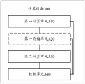
- FIG. 3 is a schematic structural diagram of a computing device according to an embodiment of the present application.
- FIG. 4 is a diagram showing an example of the structure of a line buffer of an embodiment of the present application.
- FIG. 5 is a comparison diagram of a line buffer storage state and a convolution operation process according to an embodiment of the present application.
- FIG. 6 is a schematic structural diagram of a computing device according to another embodiment of the present application.
- FIG. 7 is a schematic structural diagram of a computing device according to still another embodiment of the present application.
- Figure 8 is a diagram showing an example of a convolution operation of one embodiment of the present application.
- FIG. 9 is a diagram showing an example of a convolution operation of another embodiment of the present application.
- FIG. 10 is a schematic flowchart of a calculation method for neural network calculation according to an embodiment of the present application.
- neural network and computing devices for neural network computing are first described in detail.
- a neural network generally includes a plurality of neural network layers, each of which can implement different operations or operations.
- Common neural network layers include convolutional layers, pooled layers, fully connected layers, and the like. There are many ways to combine adjacent neural network layers. The more common combinations include: convolution layer-convolution layer and convolution layer-pooling layer-convolution layer.
- the convolution layer is mainly used to perform convolution operations on the input matrix
- the pooling layer is mainly used to perform pooling operations on the input matrix. Whether it is a convolution operation or a pooling operation, one core can be corresponding, and the core corresponding to the convolution operation can be called a convolution kernel.
- the convolution operation and the pooling operation are described in detail below.
- the convolution operation is mainly used in the field of image processing.
- the input matrix can also be called a feature map.
- the convolution operation corresponds to a convolution kernel.
- a convolution kernel can also be called a weight matrix, and each element in the weight matrix is a weight.
- the input matrix is divided into a number of sub-matrices of the same size as the weight matrix by the sliding window.
- Each sub-matrix is matrix-multiplied with the weight matrix, and the result is the weighted average of the data elements in each sub-matrix.
- the input matrix is a 3 x 3 matrix.
- the size of the sliding window represents the size of the convolution kernel.
- Figure 3 illustrates the weight matrix with a convolution kernel of 3 ⁇ 3 as an example.
- the sliding window can be slid according to the position of the upper left corner of the input matrix, and is slid according to a certain sliding step s.
- the output matrix is obtained by performing 9 convolution operations in the manner shown in Figure 3, where the first convolution operation yields the elements of the output matrix (1, 1), and the second convolution operation yields the output.
- the convolution operation generally requires that the dimensions of the input matrix and the output matrix are consistent, but the embodiment of the present application is not limited thereto, and the dimensions of the input matrix and the output matrix may not be required to be consistent. If the convolution operation does not require the input matrix and the output matrix dimensions to be consistent, the input matrix may not be padded with zeros before performing the convolution operation.
- Pooling operations are generally used to reduce the dimensions of the input matrix by downsampling the input matrix.
- the pooling operation is similar to the convolution operation and is also based on a check input matrix. Therefore, there is also a sliding window, and the sliding step size of the pooling operation is usually greater than 1 (which can also be equal to 1).
- the pooling process is roughly similar to the convolution process, except that the data elements in the sliding window are operated differently and will not be described in detail here.
- a computing device for neural network computing (which may be, for example, a neural network accelerator) includes computing units corresponding to respective neural network layers, each of which corresponds to a computing unit that is operable to perform operations or operations of the neural network layer. It should be noted that the computing units corresponding to the neural network layers may be integrated or separated from each other, which is not specifically limited in this embodiment of the present application.
- the computing unit can be implemented using a logic computing circuit or a cross array.
- the logic calculation circuit may be, for example, a logic metal circuit based on a complementary metal-oxide-semiconductor transistor (CMOS).
- CMOS complementary metal-oxide-semiconductor transistor
- a computing unit in the form of a cross array is a computing unit that has recently been widely used.
- the connection weights of neurons can be stored in a non-volatile memory (Non Volatile Memory, NVM) of a cross array. in. Since the NVM can still store data efficiently in the event of a power loss, this can reduce the storage overhead of the computing device.
- NVM Non Volatile Memory
- the crossbar (xbar) has a row-column cross structure.
- Each cross node is provided with NVM (hereinafter referred to as a cross node as an NVM node) for storing data and calculations.
- NVM hereinafter referred to as a cross node as an NVM node
- the embodiment of the present application does not specifically limit the type of the NVM in the NVM node, and may be, for example, a resistive random access memory (RRAM), a ferroelectric random access memory (FeRAM), or a magnetic random access memory (magnetic). Random access memory (MRAM), phase-change random access memory (PRAM), etc.
- RRAM resistive random access memory
- FeRAM ferroelectric random access memory
- MRAM phase-change random access memory
- PRAM phase-change random access memory
- the cross array Since the calculation of the neural network layer is mainly based on vector-matrix multiplication or matrix-matrix multiplication, the cross array is very suitable for neural network calculation.
- the basic working principle of the cross array in neural network calculation is described in detail below.
- Each NVM node in the cross array is first initialized to store the connection weights of the neurons.
- the cross array as an example for performing the convolution operation of the convolutional layer, as shown in FIG. 2, it is assumed that the convolutional layer performs T kinds of convolution operations, since each convolution operation corresponds to one two-dimensional convolution kernel (convolution)
- the kernel is a weight matrix and therefore is two-dimensional). Therefore, each two-dimensional convolution kernel can be vector-expanded to obtain a one-dimensional convolution kernel vector, and then the convolution kernel vector is mapped to the cross array T.
- the NVM nodes of each column store a convolution kernel vector.
- the 3 ⁇ 3 convolution kernel can be vector-expanded to obtain a one-dimensional convolution kernel vector containing nine data elements, and then one-dimensional.
- the nine data elements of the convolution kernel vector are respectively stored in nine NVM nodes of a column of the cross array, and the data elements stored by each NVM node can be represented by the resistance value (or conductance value) of the NVM node.
- Each submatrix of the input matrix performs a convolution operation.
- Each submatrix can be converted to a vector to be computed before each submatrix is subjected to a convolution operation.
- the dimension of the vector to be calculated is n, to be calculated
- the n elements in the vector are represented by digital signals D1 to Dn, respectively.
- the digital signals D1 to Dn are converted into analog signals V1 to Vn by an analog to digital converter (DAC), and at this time, n elements in the vector to be calculated are represented by analog signals V1 to Vn, respectively.
- the analog signals V1 to Vn are input to n rows of the cross array, respectively.
- the conductance value of the NVM node of each column in the cross array represents the magnitude of the weight stored by the NVM node, and therefore, after the analog signals V1 to Vn act on the corresponding NVM nodes of each column, the output of each NVM node
- the current value represents the product of the weight stored by the NVM node and the data element represented by the analog signal received by the NVM node. Since each column of the cross array corresponds to one convolution kernel vector, the sum of the output currents of each column represents the operation result of the matrix product of the convolution kernel corresponding to the column and the submatrix corresponding to the vector to be calculated. Then, as shown in FIG. 2, the operation result of the matrix product is converted from an analog quantity to a digital quantity by an analog to digital converter (ADC) at the end of each column of the cross array.
- ADC analog to digital converter
- the cross array converts the matrix-matrix multiplication into a multiplication of two vectors (the vector to be calculated and the convolution kernel vector), and can quickly obtain the calculation result based on the simulation calculation, which is very suitable for processing the vector - Matrix multiplication or matrix-matrix multiplication operations. Since more than 90% of the operations in the neural network are such operations, the cross array is well suited as a computational unit in neural networks, especially for convolution operations.
- the computing device for neural network computing further includes a storage unit for storing intermediate data of each neural network layer or connection weights of the neurons (if the computing unit is a cross array, the connection weights of the neurons can be stored In the NVM node of the cross array).
- the storage unit of a conventional computing device for neural network computing is generally implemented by a dynamic random access memory (DRAM) or an enhanced dynamic random access memory (eDRAM).
- DRAM dynamic random access memory
- eDRAM enhanced dynamic random access memory
- neural networks are characterized by computationally intensive and intensive memory access. Therefore, a large amount of storage resources are needed to store intermediate data obtained by each neural network layer, and the storage overhead is large.
- FIG. 3 is a schematic structural diagram of a computing device for neural network calculation provided by an embodiment of the present application.
- the neural network includes a Kth neural network layer and a K+1th neural network layer, and the operation performed by the Kth neural network layer includes a first operation, where K is a positive integer not less than one,
- Computing device 300 includes a first computing unit 310, a second computing unit 330, and a control unit 340.
- the first calculating unit 310 is configured to perform M first operations on the input first matrix to obtain a second matrix, where M is a positive integer not less than 1.
- the second calculating unit 330 is configured to perform a second operation on the input second matrix.
- the control unit 340 is used to:
- the ith data element of the second matrix is stored in the first storage unit 320;
- the second computing unit 330 is controlled to perform a second operation
- the first operation is a convolution operation
- the second operation is a convolution operation or a pooling operation, or the first operation is a pooling operation
- the second operation is a convolution operation.
- the K+1 neural network layer starts to calculate. Therefore, the computing device needs to store all the calculation results of the Kth neural network layer, resulting in a large storage overhead of the computing device.
- the second calculation may be controlled before the first operation of the input matrix is completed by the Kth neural network layer.
- the unit performs a second operation.
- the embodiment of the present application does not require the calculation of the K+1 neural network layer after the calculation of the Kth neural network layer is completed, once the first storage unit stores data that can be used to perform a second operation. Element, you can control the K+1 neural network layer to perform a second operation through the flow control mechanism between layers, which can improve the efficiency of neural network calculation.
- the K+1 neural network layer is triggered to perform calculation before the calculation of the Kth neural network layer is completed, it means that the first storage unit does not need to simultaneously store all the calculations of the Kth neural network layer.
- the intermediate data only needs to store part of the intermediate data between the Kth neural network layer and the K+1 neural network layer, which can reduce the data storage overhead.
- the first computing unit 310 is configured to perform M first operations on the input matrix.
- M represents the number of times the input matrix needs to perform the first operation.
- the specific value of the M is related to one or more of the dimensions of the input matrix, the type of the first operation, the size of the sliding window corresponding to the first operation, the sliding step size, and the like, which are not specifically limited in this embodiment of the present application.
- the input matrix is a 3 ⁇ 3 matrix
- the sliding window has a size of 3 ⁇ 3
- the sliding step size is 1
- M is equal to 9.
- the first storage unit 320 is configured to store the output matrix calculated by the first computing unit 310. It should be understood that the output matrix is relative to the first computing unit 310, which is actually the input matrix of the second computing unit 320.
- the type of the first storage unit 320 is not specifically limited in the embodiment of the present application.
- the first storage unit 320 can be a DRAM; in some embodiments, the first storage unit 310 can be an eDRAM; in some embodiments, the first storage unit 320 can be a line buffer. LB).
- the following is a detailed description of the first storage unit 320 being an LB, and details are not described herein again.
- the first storage unit 320 can be part of the computing device 300.
- the first storage unit 320 can be integrated with a computing unit in the computing device 300 on a single chip, dedicated to neural network computing.
- the first storage unit 320 can be a memory located external to the computing device 300.
- the computing device of the embodiment of the present application may be a general computing device supporting neural network computing, or may be a computing device dedicated to neural network computing, for example, may be a neural network accelerator.
- the control unit 340 in the embodiment of the present application is mainly used to implement control logic in the computing device 300.
- the control unit 340 may be a complete control unit or a plurality of separate sub-units.
- the embodiment of the present application does not specifically limit the type of the first computing unit 310.
- the cross-array implementation may be implemented, or may be implemented by using a logic computing circuit, such as a CMOS-based logic computing circuit.
- the control unit 340 controls the second computing unit 330 to perform a second operation.
- the control unit 340 controls the second calculation unit 330 to perform the second operation once.
- the second calculation unit 330 performs the first pooling operation and needs to obtain the second matrix.
- the first computing unit 310 is performing the fifth volume.
- the first storage unit 320 obtains the elements (2, 2) of the second matrix.
- the first storage unit 320 stores the elements (1, 1), (1, 2), (1) of the second matrix.
- these elements contain the elements required by the second calculation unit 330 to perform the first pooling operation, that is, the elements of the second matrix (1, 1), ( 1,2), (2,1), (2,2). Therefore, after the first calculation unit 310 performs the fifth convolution operation, the second calculation unit 330 can be controlled to perform a pooling operation.
- the first computing unit 310 may be a cross array, and the first operation may be a convolution operation.
- the second computing unit 330 can be a cross array and the second operation can be a convolution operation.
- the size of the core of the first operation and the core of the second operation may be the same.
- the cross array converts the operation based on the digital signal into an operation based on the analog signal (referred to as an analog operation) through the ADC, and the simulation operation has the characteristics of fast calculation speed, and can improve the calculation of the neural network. effectiveness. Further, the cross array stores the convolution kernel in the NVM node of the cross array, and the NVM node has a non-volatile characteristic. Therefore, the convolution kernel is not stored in the storage unit, and the storage overhead of the storage unit is reduced.
- computing device 300 may further include first storage unit 320.
- the first storage unit 320 can include a first line buffer 410.
- Each register 420 in the first line buffer 410 can be used to store one element in the matrix.
- a line buffer may also be referred to as a line cascade register, or a line buffer.
- a line buffer can be formed by connecting a plurality of registers end to end, and each register is used to store a data element.
- the registers in the line buffer can also be called shift registers. Whenever the first register of the line buffer stores a new data element, the old data elements in the line buffer are shifted backwards. Data elements in a register can be discarded.
- the storage medium of the register 420 is not specifically limited in the embodiment of the present application.
- the storage medium of the register 420 may be a static random access memory (SRAM) or an NVM.
- a first storage unit 320 may include line buffers C in (C in ⁇ 1).
- the first line buffer 410 may be any one of C in line buffers.
- C in may represent the number of convolution kernels included in the first computing unit 310.
- each convolution kernel stored in the first calculation unit 310 may correspond to a line buffer.
- the control unit 340 convolves the convolution.
- the intermediate data obtained by the kernel calculation is stored in the line buffer corresponding to the convolution kernel.
- the computing device provided by the embodiment of the present application uses a line buffer as a storage unit.
- the line buffer has the characteristics of simple operation and fast addressing, and can improve the efficiency of neural network calculation.
- the first line buffer 410 can include N registers 420.
- the N registers 420 in the first line buffer 410 may be sequentially stored in each element of the third matrix in a row-first or column-first manner.
- the third matrix is a matrix obtained by performing a second operation on the second matrix to complement the second matrix, wherein N is greater than or equal to (h-1) ⁇ (W+p)+w.
- h may represent the number of rows of the core corresponding to the second operation.
- w may represent the number of columns of the core corresponding to the second operation.
- W can represent the number of columns of the second matrix.
- p may represent the number of rows or columns of 0 elements that need to be added to the second matrix in order to perform the second operation on the second matrix.
- h, w, p, W, and N are positive integers not less than one.
- the N registers 420 in the first line buffer 410 can be sequentially stored in each element of the third matrix in a row-first or column-first manner.
- the row priority means that the first line buffer 410 first reads the 0th of the third matrix in sequence. From the 0th element of the line to the end element, the 0th element of the 1st line of the third matrix is read in turn to the end element, and so on.
- the column priority means that the first line buffer 410 first reads the 0th element of the 0th column of the third matrix to the last element, and then sequentially reads the 0th element of the 1st column of the third matrix to the last element. And so on.
- the first line buffer 410 reads the elements in the third matrix in a row-first manner, or reads the elements in the third matrix in a column-first manner depending on the sliding direction of the sliding window corresponding to the second operation. If the sliding window corresponding to the second operation first slides along the row of the matrix, the first line buffer 410 may read the elements in the third matrix in a row-first manner; if the sliding window corresponding to the second operation first follows the matrix The column slides, then the first line buffer 410 can read the elements in the third matrix in a column-first manner.
- the second operation is a convolution operation
- the dimensions of the input matrix and the output matrix are generally required to be consistent. Therefore, the second matrix needs to be complemented by 0 to obtain a third matrix, but the embodiment of the present application is not limited thereto.
- the input matrix and the output matrix may not be required to be consistent.
- the number of rows and/or the number of columns to be complemented by the second matrix is 0 (ie, the second matrix does not need to be performed).
- N (h-1) x (W + p) + w.
- both h and w are 3, that is, the convolution kernel of the second operation is a 3x3 convolution kernel, and the first line buffer contains 13 registers.
- the input matrix shown in FIG. 1 is regarded as the second matrix, and the third matrix may be a 5 ⁇ 5 matrix obtained by adding 0 to the second matrix shown in FIG. 1 . Assuming that the sliding windows are sequentially slid in the manner shown in FIG.
- the first line buffer 410 sequentially reads each element of the third matrix in a row-first manner.
- the first line buffer 410 stores the second calculation unit to execute the first The element required for the second second operation (the element stored in the register in the dotted line box in FIG. 5 is the element required for the second calculation unit to perform the first second operation), and at this time, the second calculation unit can be controlled 330 performs the first second operation.
- the first line buffer 410 reads the 14th element of the third matrix in a row-first manner (corresponding to the storage state 2 of FIG.
- the first line buffer 410 stores the second calculation unit.
- the elements required for the second second operation are performed, and at this time, the second calculation unit 330 can be controlled to perform the second second operation.
- the first line buffer 410 reads the 15th element of the third matrix in a row-first manner (corresponding to the storage state 3 of FIG. 5)
- the first line buffer 410 stores the second calculation sheet.
- the 330 element performs the elements required for the third second operation, and at this time, the second calculation unit 330 can be controlled to perform the third second operation.
- the first line buffer 410 reads the 16th element and the 17th element of the third matrix in a row-first manner (corresponding to the storage state 4 and the storage state 5 of FIG.
- the first line The element stored in the buffer 410 is insufficient, and the second calculating unit 330 is still unable to perform the fourth second operation.
- the control unit 340 can control the second calculating unit to enter a sleep state.
- the first line buffer 410 reads the 18th element of the third matrix in a row-first manner (corresponding to the storage state 6 of FIG. 5)
- the first line buffer 410 stores the second calculation sheet.
- the 330 element performs the elements required for the fourth second operation, and at this time, the second calculation unit 330 can be controlled to perform the fourth second operation.
- the latter process is similar and will not be described in detail here.
- the number of N registers in the first line buffer 410 is set such that the N registers cannot simultaneously store all the data elements calculated by the first calculation unit, and the second The data elements required by the computing unit 330 to perform any one of the second operations will always appear in the first line buffer 410, specifically in the registers within the dashed box as shown in FIG.
- the number of registers in the first line buffer 410 is less than (h-1) ⁇ (W+p)+w, there is no guarantee that the data elements required for the second calculation unit 330 to perform any one of the second operations will always appear in the first line buffer 410; if the first line buffer 410 If the number of registers is greater than (h-1) ⁇ (W + p) + w, there will be a waste of register resources.
- the first buffer 410 is read into the data element calculated by the first calculating unit 310, or is complemented by 0, and can be implemented by the two-way selector MUX.
- the first buffer 410 may include a controller and a two-way selector MUX, and the controller sends a control signal to the two-way selector MUX, and the control MUX is read and read by the first calculating unit 310.
- the resulting data element is still filled with 0.
- the control signals issued by the controller can come from pre-stored control commands or logic.
- the second computing unit is a cross array
- the X target registers 420 of the N registers 420 are directly connected to the X rows of the second computing unit 330, respectively.
- the control unit 340 is specifically configured to store the ith data element of the second matrix into the first line buffer 410; if the data element currently stored by the X target registers 420 can be used to perform a second operation, control the second calculation Unit 330 operates to perform a second operation on the data elements stored in the X target registers 420.
- the data elements required for the second calculation unit 330 to perform any one of the second operations will always appear in the nine registers.
- the embodiment of the present application utilizes this feature of the first line buffer 410 to directly connect the X target registers 420 with the X rows of the second computing unit 330, so that the control unit does not need to perform an addressing operation, and only needs to When the X target registers 420 store the data elements required to perform the second operation once, the second computing unit is controlled to enter the active state from the sleep state, and the second operation may be performed once. Therefore, directly connecting the above X target registers 420 to the X rows of the second calculation unit 330 avoids the addressing operation, thereby improving the efficiency of the neural network calculation.
- directly connecting the X target registers 420 to the X rows of the second computing unit 330 may refer to hardwire connecting the X target registers 420 with the X rows of the second computing unit 330, respectively.
- control unit 340 is specifically configured to: in the nth clock cycle, control the first calculating unit 310 to perform the ith first operation on the first matrix, to obtain the ith of the second matrix.
- a data element, the i-th data element of the second matrix is located in the last column of the second matrix, the i+1th data element of the second matrix is located at the beginning of the next row of the row of the i-th data element, or the second The i-th data element of the matrix is located in the last row of the second matrix, and the i+1th data element of the second matrix is located at the beginning of the next column of the column in which the i-th data element is located;
- the control unit 340 is further configured to: n+t clock cycle, controlling the first calculating unit 310 to perform the i+1th first operation in the Mth first operation on the first matrix, t is a positive integer greater than 1; in the n+1th clock cycle to the n+t clock cycle At least one clock cycle between, controlling
- first computing unit 310 performs a first operation on the input first matrix, in some embodiments, if the first operation is a convolution operation requiring the input matrix and the output matrix dimensions to be consistent, before performing the first operation, The first matrix needs to be complemented by 0 to obtain a fourth matrix. Further, in some embodiments, in order to store elements in the fourth matrix, computing device 300 may also configure first computing unit 310 with a second storage that is identical in structure and/or functionality to first storage unit 320 above. unit.
- the second storage unit can include a second line buffer.
- the second line buffer may include N registers, and the N registers in the second line buffer are sequentially stored in each of the elements in the fourth matrix in a row-first or column-first manner.
- the second storage unit 350 can be coupled to the first computing unit 310 for storing data elements required by the first computing unit 310 to perform the first operation.
- the first storage unit 320 is coupled to the second computing unit 330 for storing data elements required by the second computing unit 330 to perform the second operation.
- the cross array and the line buffer are alternately arranged, which is equivalent to configuring a buffer close to the cross array for each cross array, which not only improves the efficiency of memory access but also facilitates subsequent operations. Pipeline control mechanism. Taking FIG. 7 as an example, in FIG.
- the cross array of the K-1 layer of the neural network is connected to the Kth line buffer, and the cross array of the Kth layer of the neural network is connected to the K+1 line buffer.
- the K-th line buffer may include C in1 line buffers, and C in1 represents the number of convolution kernels included in the cross-array of the K- 1th layer of the neural network.
- the first K + 1 may include a line buffer C in2 line buffers, C in2 represents the number of intersections of the array located in the neural network comprises a layer K of the convolution kernel.
- the structure in which the cross array and the line buffer are alternately arranged is equivalent to configuring each computing unit with a buffer close to the computing unit, which not only improves the memory access efficiency, but also facilitates the subsequent pipeline control mechanism.
- the i-th data element of the second matrix is located in the last column of the second matrix, the i+1th data element of the second matrix is located at the beginning of the next row of the row of the i-th data element. It is indicated that the sliding window corresponding to the first operation slides in a row-first manner, and the sliding window has been slid to the end of the fourth matrix when the i-th data element of the second matrix is calculated.
- the i-th data element of the second matrix is located in the last row of the second matrix
- the i+1th data element of the second matrix is located at the beginning of the next column of the column in which the i-th data element is located, indicating the first
- the corresponding sliding window of the operation slides in a column-first manner, and the sliding window has been slid to the end of the fourth matrix when the i-th data element of the second matrix is calculated.
- the second line buffer needs to read in (s-1) ⁇ (W+p)+(w-1)
- the first computing unit 310 can perform the (i+1)th first operation. Therefore, the sliding window wrapping process introduces some idle periods. In these idle periods, the first computing unit 310 has no data element input value first buffer unit 420.
- This embodiment of the present application refers to this phenomenon as a Line Feeding bottleneck. In order to alleviate the bottleneck of the Line Feeding, the embodiment of the present application uses the idle periods to make 0 in the first buffer unit 420, and prepares for the second computing unit 330 to perform the next second operation.
- t is greater than (s-1) x (W+p) + (w-1).
- the control unit 340 may be specifically configured to: control from the n+1th clock period to the n+th clock period
- the first line buffer 410 sequentially stores (s-1) ⁇ (W + p) + (w - 1) 0 elements, and s represents the sliding step size of the first operation.
- the second line buffer needs to read in (s-1) ⁇ (W + p) + (w - 1) data. Thereafter, the first computing unit 310 can perform the next first operation.
- the embodiment of the present application sets t to (s-1) ⁇ (W+p)+(w-1), meaning that the control unit 340 only costs (s-1) ⁇ (W + p) + (w - 1) clock cycles complement the (s-1) ⁇ (W + p) + (w - 1) data required for the next second operation in the second line buffer That is, the second line buffer is controlled to read 1 new data element every clock cycle from the n+1th clock period to the n+th clock period.
- control unit 340 may control the first line buffer 410 to sequentially read in (s-1) ⁇ (W+p)+ (w-1) 0 elements to maximize the efficiency of neural network calculations.
- the following Kth neural network layer and the K+1th neural network layer are both convolutional layers.
- the first operation and the second operation are both convolution operations, and the flow control mechanism of the control unit 340 is described in detail. .
- the first computing unit since the first computing unit is configured to perform the operation of the Kth neural network layer, and the first computing unit is a cross array, the first computing unit is hereinafter referred to as a Kth cross array, and will be
- the second line buffer of the first matrix providing the first matrix is called the Kth line buffer; similarly, since the second calculating unit is used to perform the operation of the K+1th neural network layer, and the second calculating unit is a cross array Therefore, the second calculation unit is hereinafter referred to as a K+1th cross array, and the first line buffer that supplies the second matrix to the second calculation unit is referred to as a K+1th line buffer.
- Step 1 To ensure that the first matrix input of the Kth cross array and the second matrix of the output have the same dimensions, first read the first matrix by controlling the multiplexer MUX in the Kth line buffer to the Kth line buffer.
- Step 2 sequentially read the data elements of the h-1-p/2 line of the first matrix, and respectively fill the p/2 0 elements before reading the data elements at the beginning and the end of each line of the first matrix.
- Step 3 Continue to read the p/2 0 elements and the first w-1-p/2 data elements at the beginning of the h-th row of the first matrix. At this time, the K-cross array can be controlled to be in a sleep state.
- Step 4 continue to read the subsequent data elements of the hth row of the first matrix.
- the Kth line buffer is filled with the data elements required for a convolution operation, the Kth layer
- the cross array performs a convolution operation and outputs the result to the K+1 line buffer.
- Step 5 When the Kth cross array calculates the end of the line to the fourth matrix (the matrix formed after the first matrix is filled with 0), it is necessary to prepare (s-1) ⁇ (W+p)+ for the next convolution operation. W-1) data, where s is the step size. It should be noted that when the s-row data is prepared, the K-th cross array is controlled to be in a Sleep state. At this time, the K+1 line buffer cannot read the intermediate data calculated by the Kth cross array. This embodiment of the present application refers to this phenomenon as a bottle feeding bottleneck.
- the K+1 line buffer can be controlled to read the 0 element by using these blank clock cycles to make up for the previous one.
- the layer cross array has no problem of wasted clock cycles caused by the inflow of valid data elements. This pipeline control mechanism improves the efficiency of neural network calculations while ensuring that the entire pipeline takes up the shortest clock cycle.
- the Kth neural network layer and the K+1th neural network layer in the above are convolution-convolution connection structures.
- another common connection structure of the neural network layer is a convolution-pool-convolution type connection structure.
- the main principle of the pipeline control mechanism is similar to the pipeline control mechanism of the convolution-convolution type connection structure described above.
- the step size s of the pooling operation is usually greater than 1, and the calculation unit for the pooling layer (also referred to as The pooling circuit is not necessarily implemented as a cross-array.
- an NVM multi-channel comparator can be used for Max-pooling, and a cross-array can be implemented for mean-pooling.
- the computing unit of the pooling layer can be switched to the active state to perform a pooling operation.
- the computing unit of the layer needs to sleep for s-1 clock cycles per work, waiting to flow from the convolutional layer into the s data required for a pooling operation.
- the convolutional layer is calculated to the end of the matrix after the complement 0, there is also the Line Feeding problem of the above convolution-convolution type connection structure, and the convolutional layer will not output valid data to the pool in the next few clock cycles.
- the layer corresponds to the line buffer.
- the pooled layer corresponding to the line buffer is in a no valid data read state during the w-1 clock cycles, and the pooled layer computing unit is in a sleep state.
- the corresponding line buffer of the pooling layer needs to prepare the s-1 row data element before starting the calculation.
- the pooling layer The computing unit can be in a sleep state.
- the pipeline control mechanism of the control unit is basically the same as the pipeline control mechanism of the convolution-convolution type connection structure.
- the pipeline control mechanism of the convolution-convolution type connection structure refer to the pipeline control mechanism of the convolution-convolution type connection structure. Detailed.
- the cross-array output result dimension of the K-1 layer for convolution calculation is 3x3
- the size of each layer of convolution kernel is 3x3
- the sliding step size s is 1.
- the original output result feature map of the K-1 layer cross array is required. Fill in the periphery.
- the input matrix of the Kth layer to be convoluted has a dimension of 3x3, and needs to be complemented by a zero, so that the input matrix has a dimension of 5x5, wherein the input matrix can be a K-1 layer cross array.
- the output which can also be raw input data (such as raw data such as images, sounds, or text).
- the size of the convolution kernel to be calculated is 3x3, and the original input matrix needs to be complemented by a zero to match the dimensions of the input and output results.
- the working principle of the line buffer proposed in the embodiment of the present application is that the data to be calculated will be sequentially flowed into the line buffer in a row reading manner, as shown in FIG.
- the value of the third row and the fourth column of the input matrix after zero-padding is written to the MUX in the control line buffer, and the old data in the line buffer is sequentially shifted by one bit.
- the corresponding data element in the line buffer to be convoluted (the data element stored in the register in the dotted line of FIG. 8) is directly read into the subsequent cross array for operation. Data elements are computationally time-intensive from reading the line buffer to flowing into the subsequent cross-array, and can typically be completed in one clock cycle.
- the pipeline control mechanism proposed in the embodiment of the present application is introduced by taking the convolution-convolution type neural network structure as an example, and the calculation result dimension of the output from the cross array is 3 ⁇ 3, and the convolution kernel is assumed.
- the size is 3x3, and the dimensions of the input and output of the convolutional layer are guaranteed to be consistent by zero-padding the results of the output from the cross array.
- the specific control method of the pipeline proposed in the present application is as follows:
- Step 1 Using 5 clock cycles, the multiplexer MUX is controlled to read the zero-padded data of the first row to the K+1th line buffer, and the K-th layer cross array is in a sleep state.
- Step 2 Using one clock cycle, continue to read the first 0 element at the beginning of the second row, and the Kth layer cross array is in a sleep state.
- Step 3 Continue to control the MUX to sequentially read the calculated output results (1, 1), (1, 2), (1, 3) and a 0 element at the end of the second line from the K-1 layer cross array (a total of 4) Clock cycle), at this time, the Kth layer cross array is in a sleep state. And in the four clock cycles from the reading of the first valid calculation input result (1, 1) from the K-1 layer cross array, the K+1th layer linear cascade register starts with the four clock cycles. The output matrix of the K-th layer cross array is calculated to read the first four zeros of the first row, and the K+1th cross array is in a sleep state.
- Step 4 continue to read the first 0 element of the third row row for the Kth line buffer, and read the third row first column original calculation output result (2, 1) from the K-1 layer cross array ( It takes a total of 2 clock cycles). During these two clock cycles, the Kth layer cross array is still asleep. At the same time, in the two clock cycles, the K+1 layer line buffer continues to read the 0 element at the end of the first line and the 0 element at the beginning of the third line. At this time, the K+1 layer cross array Sleeping.
- Step 5 In the next clock cycle, the Kth line buffer reads the third row and the second column of the original calculation output result (2, 2) from the K-1 layer cross array, as shown in FIG.
- the layer line buffer stores data satisfying the one-th unit convolution operation of the K-th layer cross-array. Since the cross-array is an analog calculation, in this clock cycle, the buffered data can be simultaneously flowed into the K-th layer cross-array for one time. Multiply accumulate (convolution) calculation, and the calculation result (1,1) flows into the K+1th line buffer, while the Kth layer cross array is in an active state, and the K+1th cross array is in a sleep state. .
- Step 6 In the following two clock cycles, read the valid output (2, 3) of the third row and the third column and the 0 element at the end of the third row from the K-1 layer cross array, respectively, for the Kth
- the layer cross array performs two convolution operations, and the output results (1, 2) and (1, 3) flow into the K+1th line buffer.
- the Kth layer cross array The convolution operation is active, while the K+1th layer cross array is still asleep, waiting for the K+1 line buffer to buffer the data required for a convolution operation.
- Step 7 In the next two clock cycles, the Kth line buffer needs to first cache the 0 element at the beginning of the fourth row, and then receive the computed output from the K-1 layer cross array (3, 1). .
- the Kth layer cross array is in a sleep state, waiting for the Kth line buffer to buffer the data required for a convolution operation.
- the K-th layer cross array since the K-th layer cross array has no valid calculation output, it flows into the K+1-layer line buffer, K+ The 1-layer line buffer is in the Line Feeding state, and the K+1-th layer cross array is in the sleep state.
- the MUX of the K+1 layer line buffer is controlled by the two clock cycles as the output matrix of the Kth layer cross array.
- the zero-padding operation is performed at the end of the second row and the beginning of the next row, so that the problem that the K+1-layer line buffer output from the K-th layer cross-array has no valid data inflow in the two clock cycles can be compensated.
- Step 8 the Kth layer line buffer reads the inflow data (3, 2) from the K-1 layer cross array, and the Kth layer cross array switches from the sleep state to the active state to sequentially multiply and accumulate (volume) The calculation is performed, and the calculation result (2, 1) flows into the K+1th line buffer, at which time the K+1th layer cross array is in a sleep state.
- Step 9 the Kth line buffer receives the output calculation result (3, 3) from the K-1 layer cross array, and the Kth layer cross array is in an active state for a convolution calculation, and will calculate The output result (2, 2) flows into the K+1th line buffer.
- the K+1th layer cross array is switched from the sleep state to the active state, a convolution calculation is performed, and the calculation result flows into the next layer (K+2 layer) line buffer in the same manner.
- the method embodiments of the present application are described below.
- the method embodiments correspond to the device embodiments. Therefore, the parts that are not described in detail may be referred to the foregoing device embodiments.
- FIG. 10 is a schematic flowchart of a calculation method for neural network calculation according to an embodiment of the present application.
- the neural network includes a Kth neural network layer and a K+1th neural network layer, the operation performed by the Kth neural network layer includes a first operation, and the operation performed by the K+1th neural network layer includes a second operation
- the K is a positive integer not less than 1
- the computing device to which the computing method is applied includes: a first calculating unit, configured to perform the first operation M times on the input first matrix to obtain a second matrix, where M is a positive integer not less than 1; a second calculating unit, configured to perform the second operation on the input second matrix;
- the computing method of FIG. 10 includes:
- the first computing unit is configured to perform an ith first operation in the M first operations on the first matrix to obtain an ith data element of the second matrix, where 1 ⁇ i ⁇ M ;
- the first operation is a convolution operation
- the second operation is a convolution operation or a pooling operation, or the first operation is a pooling operation
- the second operation is a convolution operation.
- the computing device includes the first storage unit, the first storage unit includes a first line buffer, and the first line buffer includes N registers, N registers in a line buffer are sequentially stored in each of the elements of the third matrix in a row-first or column-first manner, the third matrix being for performing the second operation on the second matrix
- the second computing unit is a cross array, and X target registers of the N registers are directly connected to X rows of the second computing unit, respectively, the X targets
- step 1020 may include: storing an ith data element of the second matrix into the first line buffer;
- step 1030 may include: if the X target registers are currently stored The data element can be used to perform a second operation, control the second computing unit to operate, and perform a second operation on the data elements stored in the X target registers.
- step 1010 may include: controlling, at the nth clock cycle, the first computing unit to perform the ith first operation on the first matrix, to obtain the second matrix
- the i-th data element, the i-th data element of the second matrix is located in a last column of the second matrix, and the i+1th data element of the second matrix is located at the i-th data element a starting position of a next row of the row, or an i th data element of the second matrix is located in a last row of the second matrix, and an i+1th data element of the second matrix is located in the ith data
- the 10 may further include: controlling, in the n+th clock cycle, the first calculating unit to perform the M first operation on the first matrix
- the i+1th first operation, t is a positive integer greater than 1; controlling the first line during at least one clock cycle between the n+1th clock cycle and the n+th clock cycle
- the buffer stores 0 elements.
- t (s-1) ⁇ (W+p)+(w-1), the n+1th clock cycle to the n+t clock cycle Controlling the first line buffer to store 0 elements for at least one clock cycle between, including: controlling the first line buffer during the (n+1)th clock cycle to the (n+thth)th clock cycle Deposited in sequence (s-1) ⁇ (W+p)+(w-1) 0 elements, s represents the sliding step size of the first operation.
- the first computing unit is a cross array.
- the disclosed systems, devices, and methods may be implemented in other manners.
- the device embodiments described above are merely illustrative.
- the division of the unit is only a logical function division.
- there may be another division manner for example, multiple units or components may be combined or Can be integrated into another system, or some features can be ignored or not executed.
- the mutual coupling or direct coupling or communication connection shown or discussed may be an indirect coupling or communication connection through some interface, device or unit, and may be in an electrical, mechanical or other form.
- the units described as separate components may or may not be physically separated, and the components displayed as units may or may not be physical units, that is, may be located in one place, or may be distributed to multiple network units. Some or all of the units may be selected according to actual needs to achieve the purpose of the solution of the embodiment.
- each functional unit in each embodiment of the present application may be integrated into one processing unit, or each unit may exist physically separately, or two or more units may be integrated into one unit.
- the functions may be stored in a computer readable storage medium if implemented in the form of a software functional unit and sold or used as a standalone product.
- the technical solution of the present application which is essential or contributes to the prior art, or a part of the technical solution, may be embodied in the form of a software product, which is stored in a storage medium, including
- the instructions are used to cause a computer device (which may be a personal computer, server, or network device, etc.) to perform all or part of the steps of the methods described in various embodiments of the present application.
- the foregoing storage medium includes: a U disk, a mobile hard disk, a read-only memory (ROM), a random access memory (RAM), a magnetic disk, or an optical disk, and the like, which can store program codes. .
Landscapes
- Engineering & Computer Science (AREA)
- Physics & Mathematics (AREA)
- Theoretical Computer Science (AREA)
- Artificial Intelligence (AREA)
- Health & Medical Sciences (AREA)
- Software Systems (AREA)
- Evolutionary Computation (AREA)
- Biophysics (AREA)
- Life Sciences & Earth Sciences (AREA)
- Biomedical Technology (AREA)
- General Physics & Mathematics (AREA)
- General Engineering & Computer Science (AREA)
- Computing Systems (AREA)
- Mathematical Physics (AREA)
- Data Mining & Analysis (AREA)
- Molecular Biology (AREA)
- Computational Linguistics (AREA)
- General Health & Medical Sciences (AREA)
- Neurology (AREA)
- Computer Vision & Pattern Recognition (AREA)
- Medical Informatics (AREA)
- Automation & Control Theory (AREA)
- Complex Calculations (AREA)
Abstract
一种用于神经网络计算的计算设备(300)和计算方法,该计算设备(300)包括:第一计算单元(310),用于对输入的第一矩阵执行M次第一操作,得到第二矩阵;第二计算单元(330),用于对输入的第二矩阵执行第二操作;控制单元(340),用于控制第一计算单元(310)对第一矩阵执行M次第一操作中的第i次第一操作,得到第二矩阵的第i个数据元素;将第二矩阵的第i个数据元素存入第一存储单元(320)中;如果第一存储单元(320)当前存储的数据元素能够用于执行一次第二操作,控制第二计算单元(330)执行一次第二操作。该计算设备(300)和计算方法能够降低用于神经网络计算的计算设备(300)的存储开销。
Description
本申请要求于2017年01月13日提交中国专利局、申请号为201710025196.3、申请名称为“用于神经网络计算的计算设备和计算方法”的中国专利申请的优先权,其全部内容通过引用结合在本申请中。
本申请涉及数据处理领域,并且更具体地,涉及一种用于神经网络计算的计算设备和计算方法。
神经网络(如深度神经网络)在计算机视觉、自然语言处理、大数据挖掘等领域得到广泛应用。神经网络计算具有如下两个典型特点:
1)计算密集
神经网络主要进行的运算为多维矩阵乘法,其计算复杂度一般为O(N3)。例如,22层的googlenet一般需要6GFLOPS(Floating-point Operations Per Second,每秒所执行的浮点运算)的计算量。
2)访存密集
神经网络的训练过程一般需要海量的数据,训练过程需要大量的存储空间用于缓存神经元的连接权重以及各神经网络层计算得到的中间数据。
现有技术存在各式各样的专门用于神经网络计算的计算设备,如基于逻辑计算电路的计算设备或基于交叉阵列的计算设备。但是,现有技术中的用于神经网络计算的计算设备均需要大量的存储资源以存储各神经网络层运算得到的中间数据,对计算设备的存储容量要求较高,存储开销大。
发明内容
本申请提供一种用于神经网络计算的计算设备和计算方法,以降低用于神经网络计算的计算设备的存储开销。
第一方面,提供一种用于神经网络计算的计算设备,所述神经网络包括第K神经网络层和第K+1神经网络层,所述第K神经网络层执行的操作包括第一操作,所述第K+1神经网络层执行的操作包括第二操作,其中K为不小于1的正整数,所述计算设备包括:第一计算单元,用于对输入的第一矩阵执行M次所述第一操作,得到第二矩阵,M为不小于1的正整数;第二计算单元,用于对输入的所述第二矩阵执行所述第二操作;控制单元,用于:控制所述第一计算单元对所述第一矩阵执行所述M次第一操作中的第i次第一操作,得到所述第二矩阵的第i个数据元素,1≤i≤M;将所述第二矩阵的第i个数据元素存入第一存储单元中;如果所述第一存储单元当前存储的数据元素能够用于执行一次第二
操作,控制所述第二计算单元执行一次第二操作;其中,所述第一操作为卷积操作,所述第二操作为卷积操作或池化操作,或所述第一操作为池化操作,所述第二操作为卷积操作。
现有技术中,在第K神经网络层完成计算之后,第K+1神经网络层才会开始计算,因此,计算设备需要存储第K神经网络层的全部计算结果,导致计算设备的存储开销大。本方案中,在第K神经网络层还未完成对输入矩阵的第一操作之前,如果第一存储单元已经存储了足够执行一次第二操作所需的数据元素,则可以控制第二计算单元执行一次第二操作。换句话说,本方案不要求第K神经网络层计算完成之后,再进行第K+1神经网络层的计算,一旦第一存储单元存储了能够用于执行一次第二操作所需的数据元素,就可以通过层间的流水控制机制,控制第K+1神经网络层执行一次第二操作,这样能够提高神经网络计算的效率。
进一步地,由于本方案在第K神经网络层计算完成之前,就会触发第K+1神经网络层进行计算,意味着第一存储单元无需同时存储第K神经网络层计算得到的的全部中间数据,仅需要存储第K神经网络层和第K+1神经网络层之间的部分中间数据,可以降低数据的存储开销。
结合第一方面,在第一方面的某些实现方式中,所述计算设备包括所述第一存储单元,所述第一存储单元包括第一线缓冲器,所述第一线缓冲器包括N个寄存器,所述第一线缓冲器中的N个寄存器按照行优先或列优先的方式依次存入第三矩阵的每个元素,所述第三矩阵是为了对所述第二矩阵执行所述第二操作对所述第二矩阵进行补0之后得到的矩阵,其中N=(h-1)×(W+p)+w,h表示所述第二操作对应的核的行数,w表示所述第二操作对应的核的列数,W表示所述第二矩阵的列数,p表示为了对所述第二矩阵执行所述第二操作需要对所述第二矩阵补充的0元素的行数或列数,其中h、w、p、W、N均为不小于1的正整数。
通过设置N=(h-1)×(W+p)+w使得第一线缓冲器以最小的存储代价实现了神经网络层层间的数据缓存。
结合第一方面,在第一方面的某些实现方式中,所述第二计算单元为交叉阵列,所述N个寄存器中的X个目标寄存器分别与所述第二计算单元的X行直接连接,所述X个目标寄存器为所述N个寄存器中的第1+k×(W+p)个寄存器至第w+k×(W+p)个寄存器,其中,k为取值从0至h-1的正整数,X=h×w;所述控制单元具体用于:将所述第二矩阵的第i个数据元素存入所述第一线缓冲器中;如果所述X个目标寄存器当前存储的数据元素能够用于执行一次第二操作,控制所述第二计算单元工作,对所述X个目标寄存器中存储的数据元素执行一次第二操作。
将上述X个目标寄存器分别与第二计算单元的X行直接连接,无需进行复杂的寻址操作即可将待计算数据输入至第二计算单元,提高了神经网络计算的效率。
结合第一方面,在第一方面的某些实现方式中,所述第一计算单元为交叉阵列,所述第一操作为卷积操作,所述第一操作的核和所述第二操作的核大小相同;所述计算设备还包括:第二存储单元,所述第二存储单元包括第二线缓冲器,所述第二线缓冲器包括N个寄存器,所述第二线缓冲器中的N个寄存器按照行优先或列优先的方式依次存入第四矩阵中的每个元素,所述第四矩阵是为了对所述第一矩阵执行所述第一操作对所述第一矩阵进行补0之后得到的矩阵;所述控制单元具体用于:在第n时钟周期,控制所述第一计算
单元对所述第一矩阵执行所述第i次第一操作,得到所述第二矩阵的第i个数据元素,所述第二矩阵的第i个数据元素位于所述第二矩阵的最后一列,所述第二矩阵的第i+1个数据元素位于所述第i个数据元素所在行的下一行的起始位置,或者所述第二矩阵的第i个数据元素位于所述第二矩阵的最后一行,所述第二矩阵的第i+1个数据元素位于所述第i数据元素所在列的下一列的起始位置;所述控制单元还用于:在第n+t时钟周期,控制所述第一计算单元对所述第一矩阵执行所述M次第一操作中的第i+1次第一操作,t为大于1的正整数;在所述第n+1时钟周期至所述第n+t时钟周期之间的至少一个时钟周期,控制所述第一线缓冲器存入0元素。
通过控制第一线缓冲器在第i次第一操作和第i+1次第一操作之间的空闲时钟周期内读入0元素,减少了时钟周期的浪费,提高了神经网络计算的效率。
结合第一方面,在第一方面的某些实现方式中,所述控制单元具体用于:在第n时钟周期,控制所述第一计算单元对所述第一矩阵执行所述第i次第一操作,得到所述第二矩阵的第i个数据元素,所述第二矩阵的第i个数据元素位于所述第二矩阵的最后一列,所述第二矩阵的第i+1个数据元素位于所述第i个数据元素所在行的下一行的起始位置,或者所述第二矩阵的第i个数据元素位于所述第二矩阵的最后一行,所述第二矩阵的第i+1个数据元素位于所述第i数据元素所在列的下一列的起始位置;所述控制单元还用于:在第n+t时钟周期,控制所述第一计算单元对所述第一矩阵执行所述M次第一操作中的第i+1次第一操作,t为大于1的正整数;在所述第n+1时钟周期至所述第n+t时钟周期之间的至少一个时钟周期,控制所述第一线缓冲器存入0元素。
通过控制第一线缓冲器在第i次第一操作和第i+1次第一操作之间的空闲时钟周期内读入0元素,减少了时钟周期的浪费,提高了神经网络计算的效率。
结合第一方面,在第一方面的某些实现方式中,t=(s-1)×(W+p)+(w-1),所述控制单元具体用于:在所述第n+1时钟周期至所述第n+t时钟周期,控制所述第一线缓冲器依次存入(s-1)×(W+p)+(w-1)个0元素,s表示第一操作的滑动步长。
通过控制第一线缓冲器在第i次第一操作和第i+1次第一操作之间的每个空闲时钟周期内读入1个0元素,避免了时钟周期的浪费,使得神经网络计算的效率最大化。
结合第一方面,在第一方面的某些实现方式中,所述第一计算单元为交叉阵列。
交叉阵列形式的计算单元能够将数字运算转换成模拟运算,提高了神经网络计算的效率。
第二方面,提供一种用于神经网络计算的计算方法,所述神经网络包括第K神经网络层和第K+1神经网络层,所述第K神经网络层执行的操作包括第一操作,所述第K+1神经网络层执行的操作包括第二操作,其中K为不小于1的正整数,应用所述计算方法的计算设备包括:第一计算单元,用于对输入的第一矩阵执行M次所述第一操作,得到第二矩阵,M为不小于1的正整数;第二计算单元,用于对输入的所述第二矩阵执行所述第二操作;所述计算方法包括:控制所述第一计算单元对所述第一矩阵执行所述M次第一操作中的第i次第一操作,得到所述第二矩阵的第i个数据元素,1≤i≤M;将所述第二矩阵的第i个数据元素存入第一存储单元中;如果所述第一存储单元当前存储的数据元素能够用于执行一次第二操作,控制所述第二计算单元执行一次第二操作;其中,所述第一操作为卷积操作,所述第二操作为卷积操作或池化操作,或所述第一操作为池化操作,所述
第二操作为卷积操作。
现有技术中,在第K神经网络层完成计算之后,第K+1神经网络层才会开始计算,因此,计算设备需要存储第K神经网络层的全部计算结果,导致计算设备的存储开销大。本方案中,在第K神经网络层还未完成对输入矩阵的第一操作之前,如果第一存储单元已经存储了足够执行一次第二操作所需的数据元素,则可以控制第二计算单元执行一次第二操作。换句话说,本方案不要求第K神经网络层计算完成之后,再进行第K+1神经网络层的计算,一旦第一存储单元存储了能够用于执行一次第二操作所需的数据元素,就可以通过层间的流水控制机制,控制第K+1神经网络层执行一次第二操作,这样能够提高神经网络计算的效率。
进一步地,由于本方案在第K神经网络层计算完成之前,就会触发第K+1神经网络层进行计算,意味着第一存储单元无需同时存储第K神经网络层计算得到的的全部中间数据,仅需要存储第K神经网络层和第K+1神经网络层之间的部分中间数据,可以降低数据的存储开销。
结合第二方面,在第二方面的某些实现方式中,所述计算设备包括所述第一存储单元,所述第一存储单元包括第一线缓冲器,所述第一线缓冲器包括N个寄存器,所述第一线缓冲器中的N个寄存器按照行优先或列优先的方式依次存入第三矩阵的每个元素,所述第三矩阵是为了对所述第二矩阵执行所述第二操作对所述第二矩阵进行补0之后得到的矩阵,其中N=(h-1)×(W+p)+w,h表示所述第二操作对应的核的行数,w表示所述第二操作对应的核的列数,W表示所述第二矩阵的列数,p表示为了对所述第二矩阵执行所述第二操作需要对所述第二矩阵补充的0元素的行数或列数,其中h、w、p、W、N均为不小于1的正整数。
通过设置N=(h-1)×(W+p)+w使得第一线缓冲器以最小的存储代价实现了神经网络层层间的数据缓存。
结合第二方面,在第二方面的某些实现方式中,所述第二计算单元为交叉阵列,所述N个寄存器中的X个目标寄存器分别与所述第二计算单元的X行直接连接,所述X个目标寄存器为所述N个寄存器中的第1+k×(W+p)个寄存器至第w+k×(W+p)个寄存器,其中,k为取值从0至h-1的正整数,X=h×w;所述将所述第二矩阵的第i个数据元素存入第一存储单元中,包括:将所述第二矩阵的第i个数据元素存入所述第一线缓冲器中;所述如果所述第一存储单元当前存储的数据元素能够用于执行一次第二操作,控制所述第二计算单元执行一次第二操作,包括:如果所述X个目标寄存器当前存储的数据元素能够用于执行一次第二操作,控制所述第二计算单元工作,对所述X个目标寄存器中存储的数据元素执行一次第二操作。
将上述X个目标寄存器分别与第二计算单元的X行直接连接,无需进行复杂的寻址操作即可将待计算数据输入至第二计算单元,提高了神经网络计算的效率。
结合第二方面,在第二方面的某些实现方式中,所述控制所述第一计算单元对所述第一矩阵执行所述M次第一操作中的第i次第一操作,包括:在第n时钟周期,控制所述第一计算单元对所述第一矩阵执行所述第i次第一操作,得到所述第二矩阵的第i个数据元素,所述第二矩阵的第i个数据元素位于所述第二矩阵的最后一列,所述第二矩阵的第i+1个数据元素位于所述第i个数据元素所在行的下一行的起始位置,或者所述第二矩阵
的第i个数据元素位于所述第二矩阵的最后一行,所述第二矩阵的第i+1个数据元素位于所述第i数据元素所在列的下一列的起始位置;所述计算方法还包括:在第n+t时钟周期,控制所述第一计算单元对所述第一矩阵执行所述M次第一操作中的第i+1次第一操作,t为大于1的正整数;在所述第n+1时钟周期至所述第n+t时钟周期之间的至少一个时钟周期,控制所述第一线缓冲器存入0元素。
通过控制第一线缓冲器在第i次第一操作和第i+1次第一操作之间的空闲时钟周期内读入0元素,减少了时钟周期的浪费,提高了神经网络计算的效率。
结合第二方面,在第二方面的某些实现方式中,所述第一计算单元为交叉阵列,所述第一操作为卷积操作,所述第一操作的核和所述第二操作的核大小相同;所述计算设备还包括:第二存储单元,所述第二存储单元包括第二线缓冲器,所述第二线缓冲器包括N个寄存器,所述第二线缓冲器中的N个寄存器按照行优先或列优先的方式依次存入第四矩阵中的每个元素,所述第四矩阵是为了对所述第一矩阵执行所述第一操作对所述第一矩阵进行补0之后得到的矩阵;所述控制所述第一计算单元对所述第一矩阵执行所述M次第一操作中的第i次第一操作,包括:在第n时钟周期,控制所述第一计算单元对所述第一矩阵执行所述第i次第一操作,得到所述第二矩阵的第i个数据元素,所述第二矩阵的第i个数据元素位于所述第二矩阵的最后一列,所述第二矩阵的第i+1个数据元素位于所述第i个数据元素所在行的下一行的起始位置,或者所述第二矩阵的第i个数据元素位于所述第二矩阵的最后一行,所述第二矩阵的第i+1个数据元素位于所述第i数据元素所在列的下一列的起始位置;所述计算方法还包括:在第n+t时钟周期,控制所述第一计算单元对所述第一矩阵执行所述M次第一操作中的第i+1次第一操作,t为大于1的正整数;在所述第n+1时钟周期至所述第n+t时钟周期之间的至少一个时钟周期,控制所述第一线缓冲器存入0元素。
通过控制第一线缓冲器在第i次第一操作和第i+1次第一操作之间的空闲时钟周期内读入0元素,减少了时钟周期的浪费,提高了神经网络计算的效率。
结合第二方面,在第二方面的某些实现方式中,t=(s-1)×(W+p)+(w-1),所述在所述第n+1时钟周期至所述第n+t时钟周期之间的至少一个时钟周期,控制所述第一线缓冲器存入0元素,包括:在所述第n+1时钟周期至所述第n+t时钟周期,控制所述第一线缓冲器依次存入(s-1)×(W+p)+(w-1)个0元素,s表示第一操作的滑动步长。
通过控制第一线缓冲器在第i次第一操作和第i+1次第一操作之间的空闲时钟周期内读入0元素,减少了时钟周期的浪费,提高了神经网络计算的效率。
结合第二方面,在第二方面的某些实现方式中,所述第一计算单元为交叉阵列。
第三方面,提供一种计算机可读介质,所述计算机可读介质存储用于计算设备执行的程序代码,所述程序代码包括用于执行第二方面中的方法的指令。
交叉阵列形式的计算单元能够将数字运算转换成模拟运算,提高了神经网络计算的效率。
在上述某些方面或某些方面的某种实现方式中,第一操作为卷积操作。
在上述某些方面或某些方面的某种实现方式中,第二操作为卷积操作。
在上述某些方面或某些方面的某种实现方式中,第一计算单元为交叉阵列。
在上述某些方面或某些方面的某种实现方式中,第二计算单元为交叉阵列。
在上述某些方面或某些方面的某种实现方式中,第一操作的核与第二操作的核的大小相同。
本申请提供的技术方案能够降低数据的存储开销,提高神经网络计算的效率。
图1是卷积操作的计算过程示例图。
图2是交叉阵列的结构示例图。
图3是本申请一个实施例的计算设备的示意性结构图。
图4是本申请实施例的线缓冲器的结构示例图。
图5是本申请实施例的线缓冲器存储状态与卷积操作过程的对照图。
图6是本申请另一实施例的计算设备的示意性结构图。
图7是本申请又一实施例的计算设备的示意性结构图。
图8是本申请一个实施例的一次卷积操作的示例图。
图9是本申请另一实施例的一次卷积操作的示例图。
图10是本申请实施例的用于神经网络计算的计算方法的示意性流程图。
为了便于理解,先对神经网络及用于神经网络计算的计算设备进行详细介绍。
神经网络一般包括多个神经网络层,各神经网络层可以实现不同的运算或操作。常见的神经网络层包括卷积层、池化层、全连接层等。相邻神经网络层的组合方式有多种,比较常见的组合方式包括:卷积层-卷积层和卷积层-池化层-卷积层。卷积层主要用于对输入矩阵执行卷积操作,池化层主要用于对输入矩阵执行池化操作。无论是卷积操作还是池化操作,均可对应一个核,其中卷积操作对应的核可以称为卷积核。下面对卷积操作和池化操作进行详细描述。
卷积操作主要用于图像处理领域,在图像处理领域,输入矩阵也可称为特征图。卷积操作对应一个卷积核。卷积核也可称为权矩阵,权矩阵中的每个元素为一个权值。在卷积过程中,输入矩阵会被滑动窗口划分成许多与权矩阵大小相同的子矩阵,每个子矩阵与权矩阵进行矩阵乘法,得到的结果即为每个子矩阵中的数据元素的加权平均。
为了便于理解,下面结合图1对卷积操作的过程进行举例说明。
如图1所示,输入矩阵为3×3的矩阵。为了保证输入矩阵与输出矩阵的维度一致,在对输入矩阵进行卷积操作之前,需要在输入矩阵的边缘补充2行2列0元素,从而将输入矩阵转换成5×5的矩阵。滑动窗口的尺寸代表的是卷积核的大小,图3是以卷积核为3×3的权矩阵为例进行说明的。滑动窗口可以以输入矩阵的左上角位置为起始位置,按照一定的滑动步长s进行滑动,图3是以滑动步长s=1为例进行说明的。按照图3所示的方式执行9次卷积操作,即可得到输出矩阵,其中第一次卷积操作得到的是输出矩阵的元素(1,1),第二次卷积操作得到的是输出矩阵的元素(1,2),以此类推。
应理解,卷积操作通常要求输入矩阵和输出矩阵的维度一致,但本申请实施例不限于此,也可以不要求输入矩阵和输出矩阵的维度一致。如果卷积操作不要求输入矩阵和输出矩阵维度一致,那么输入矩阵在执行该卷积操作之前,可以不补0。
还应理解,上文是以卷积操作的滑动步长s=1为例进行说明的,但本申请实施例不限于此,卷积操作的滑动步长还可以为大于1。
池化操作一般用于降低输入矩阵的维度,即对输入矩阵进行降采样。池化操作与卷积操作类似,也是基于一个核对输入矩阵进行计算,因此,也存在一个滑动窗口,且池化操作的滑动步长通常大于1(也可以等于1)。池化操作的类型有多种,如平均池化和最大池化。平均池化是将滑动窗口中的所有元素取平均。最大池化是计算滑动窗口中的所有元素的最大值。池化过程与卷积过程大致类似,不同之处在于滑动窗口中的数据元素的运算方式不同,此处不再详述。
上文指出,神经网络一般具有多个神经网络层。用于神经网络计算的计算设备(例如可以是神经网络加速器)包括对应于各神经网络层的计算单元,每个神经网络层对应的计算单元可用于执行该神经网络层的运算或操作。需要说明的是,各神经网络层对应的计算单元可以集成在一起,也可以相互分离,本申请实施例对此不做具体限定。
计算单元可以采用逻辑计算电路或交叉阵列实现。逻辑计算电路例如可以是基于互补金属氧化物半导体晶体管(complementary metal-oxide-semiconductor transistor,CMOS)的逻辑计算电路。
交叉阵列形式的计算单元是最近开始广泛使用的一种计算单元,使用交叉阵列进行神经网络运算时,可以将神经元的连接权重存储在交叉阵列的非易失性存储器(Non Volatile Memory,NVM)中。由于NVM在掉电的情况下仍然能够有效地存储数据,这样可以降低计算设备的存储开销。下面结合图2,对交叉阵列进行详细描述。
如图2所示,交叉阵列(crossbar或xbar)具有行列交叉结构。每个交叉节点设置有NVM(下称交叉节点为NVM节点),用于存储数据和计算。本申请实施例对NVM节点中的NVM的类型不做具体限定,例如可以是阻变存储器(resistive random access memory,RRAM)、铁电随机存储器(ferroelectric random access memory,FeRAM)、磁随机存储器(magnetic random access memory,MRAM)、相变随机存储器(Phase-change Random Access Memory,PRAM)等。
由于神经网络层的计算主要以向量-矩阵乘法,或矩阵-矩阵乘法为主,因此,交叉阵列很适合用于神经网络计算。下面对交叉阵列在神经网络计算中的基本工作原理进行详细描述。
首先对交叉阵列中的每个NVM节点进行初始化,使其存储神经元的连接权重。以交叉阵列用于执行卷积层的卷积操作为例,如图2所示,假设该卷积层执行T种卷积操作,由于每种卷积操作对应一个二维卷积核(卷积核是一个权矩阵,因此是二维的),因此,可以先将每个二维卷积核进行向量展开,得到一维的卷积核向量,然后将卷积核向量映射至交叉阵列的T列上,使得每列的NVM节点存储一个卷积核向量。以二维卷积核为3×3的卷积核为例,可以先将该3×3的卷积核进行向量展开,得到包含9个数据元素的一维卷积核向量,然后将一维卷积核向量的9个数据元素分别存储至交叉阵列的某一列的9个NVM节点中,每个NVM节点存储的数据元素可以通过该NVM节点的阻值(或称电导值)体现。
输入矩阵的每个子矩阵会进行一次卷积操作。在对每个子矩阵进行卷积操作之前,可以先将每个子矩阵转换成待计算向量。如图2所示,假设待计算向量的维度为n,待计算
向量中的n个元素分别通过数字信号D1至Dn表示。然后,通过模拟/数字转换器(Digital to Analog Converter,DAC)将数字信号D1至Dn转换成模拟信号V1至Vn,此时,待计算向量中的n个元素分别通过模拟信号V1至Vn表示。接着,将该模拟信号V1至Vn分别输入至交叉阵列的n行。交叉阵列中的每列的NVM节点的电导值代表的是该NVM节点存储的权值的大小,因此,当模拟信号V1至Vn作用在每列对应的NVM节点上之后,每个NVM节点输出的电流值表示该NVM节点存储的权值与该NVM节点接收到的模拟信号所表示的数据元素的乘积。由于交叉阵列的每列对应一个卷积核向量,因此,每列的输出电流总和代表的是该列对应的卷积核与待计算向量对应的子矩阵的矩阵乘积的运算结果。然后,如图2所示,通过交叉阵列每列末尾的模拟/数字转换器(Analog to Digital Converter,ADC)将矩阵乘积的运算结果从模拟量转换成数字量进行输出。
基于以上工作原理可以看出,交叉阵列将矩阵-矩阵乘法转换成两个向量(待计算向量和卷积核向量)的乘法运算,并能够基于模拟计算快速得到计算结果,非常适于处理向量-矩阵乘法或矩阵-矩阵乘法等运算。由于神经网络中90%以上的运算均为此类运算,因此,交叉阵列非常适合作为神经网络中的计算单元,尤其适合处理卷积操作。
除了计算单元之外,用于神经网络计算的计算设备还包括存储单元,用于存储各神经网络层的中间数据或神经元的连接权重(如果计算单元为交叉阵列,神经元的连接权重可存储在交叉阵列的NVM节点中)。传统的用于神经网络计算的计算设备的存储单元一般采用动态随机存取存储器(dynamic random access memory,DRAM)实现,也可以采用增强动态随机存取存储器(enhanced dynamic random access memory,eDRAM)实现。
上文指出,神经网络存在计算密集和访存密集的特点,因此,需要大量的存储资源以存储各神经网络层运算得到的中间数据,存储开销大。
为了解决上述问题,下面结合图3,详细描述本申请实施例的用于神经网络计算的计算设备。
图3是本申请实施例提供的用于神经网络计算的计算设备的示意性结构图。神经网络包括第K神经网络层和第K+1神经网络层,第K神经网络层执行的操作包括第一操作,其中K为不小于1的正整数,
计算设备300包括第一计算单元310、第二计算单元330以及控制单元340。
第一计算单元310用于对输入的第一矩阵执行M次第一操作,得到第二矩阵,其中M为不小于1的正整数。
第二计算单元330用于对输入的第二矩阵执行第二操作。
控制单元340用于:
控制第一计算单元310对第一矩阵执行M次第一操作中的第i次第一操作,得到第二矩阵的第i个数据元素,1≤i≤M;
将第二矩阵的第i个数据元素存入第一存储单元320中;
如果第一存储单元320当前存储的数据元素能够用于执行一次第二操作,控制第二计算单元330执行一次第二操作;
其中,第一操作为卷积操作,第二操作为卷积操作或池化操作,或第一操作为池化操作,第二操作为卷积操作。
现有技术中,在第K神经网络层完成计算之后,第K+1神经网络层才会开始计算,
因此,计算设备需要存储第K神经网络层的全部计算结果,导致计算设备的存储开销大。本申请实施例中,在第K神经网络层还未完成对输入矩阵的第一操作之前,如果第一存储单元已经存储了足够执行一次第二操作所需的数据元素,则可以控制第二计算单元执行一次第二操作。换句话说,本申请实施例不要求第K神经网络层计算完成之后,再进行第K+1神经网络层的计算,一旦第一存储单元存储了能够用于执行一次第二操作所需的数据元素,就可以通过层间的流水控制机制,控制第K+1神经网络层执行一次第二操作,这样能够提高神经网络计算的效率。
进一步地,由于本申请实施例在第K神经网络层计算完成之前,就会触发第K+1神经网络层进行计算,意味着第一存储单元无需同时存储第K神经网络层计算得到的的全部中间数据,仅需要存储第K神经网络层和第K+1神经网络层之间的部分中间数据,可以降低数据的存储开销。
上文指出第一计算单元310用于对输入矩阵执行M次第一操作。M表示输入矩阵需要执行第一操作的次数。M的具体数值与输入矩阵的维度、第一操作的类型、第一操作对应的滑动窗口的大小、滑动步长等因素中的一个或多个有关,本申请实施例对此不做具体限定。以图1为例,输入矩阵为3×3的矩阵,滑动窗口的大小为3×3,滑动步长为1,则M等于9。
上文指出,第一存储单元320用于存储第一计算单元310计算得到的输出矩阵。应理解,输出矩阵是相对于第一计算单元310而言的,该输出矩阵实际上是第二计算单元320的输入矩阵。
本申请实施例对第一存储单元320的类型不做具体限定。在一些实施例中,第一存储单元320可以是DRAM;在一些实施例中,第一存储单元310可以是eDRAM;在一些实施例中,第一存储单元320可以是线缓冲器(line buffer,LB)。下文会以第一存储单元320是LB为例进行详细说明,此处不再赘述。
在一些实施例中,第一存储单元320可以为计算设备300的一部分。例如,第一存储单元320可以与计算设备300中的计算单元集成在一块芯片上,专门用于神经网络计算。在另一些实施例中,第一存储单元320可以是位于计算设备300外部的存储器。
本申请实施例的计算设备可以是通用的支持神经网络计算的计算设备,也可以是专门用于神经网络计算的计算设备,例如,可以是神经网络加速器。
本申请实施例中的控制单元340主要用于实现计算设备300中的控制逻辑,该控制单元340可以是一个完整的控制单元,也可以由多个分离的子单元组合而成。
本申请实施例对第一计算单元310的类型不做具体限定,例如,可以采用交叉阵列实现,也可以采用逻辑计算电路实现,如采用基于CMOS的逻辑计算电路实现。
上文指出,如果第一存储单元320当前存储的数据元素能够用于执行一次第二操作,控制单元340会控制第二计算单元330执行一次第二操作。换句话说,如果第一存储单元320当前存储的数据元素包含执行一次第二操作所需的数据元素,控制单元340控制第二计算单元330执行一次第二操作。
假设第二计算单元330执行的第二操作为池化操作,且第二操作对应的滑动窗口的大小为2×2,则第二计算单元330执行第1次池化操作需要获得第二矩阵的元素(1,1),(1,2),(2,1),(2,2)。以图1所示的输入矩阵是第一矩阵为例,第一计算单元310在执行第五次卷
积操作时,第一存储单元320得到第二矩阵的元素(2,2),此时,第一存储单元320存储了第二矩阵的元素(1,1),(1,2),(1,3),(2,1),(2,2),这些元素包含了第二计算单元330执行第1次池化操作所需的元素,即第二矩阵的元素(1,1),(1,2),(2,1),(2,2)。因此,第一计算单元310执行第五次卷积操作之后,可以控制第二计算单元330执行一次池化操作。
可选地,在一些实施例中,第一计算单元310可以为交叉阵列,第一操作可以为卷积操作。
可选地,在一些实施例中,第二计算单元330可以为交叉阵列,第二操作可以为卷积操作。
可选地,在一些实施例中,第一操作的核和第二操作的核的大小可以相同。
参见上文对图2实施例的描述可知,交叉阵列通过ADC将基于数字信号的运算转换成基于模拟信号的运算(简称模拟运算),模拟运算具有计算速度快的特点,可以提升神经网络计算的效率。进一步地,交叉阵列将卷积核存储在交叉阵列的NVM节点中,NVM节点具有非易失性的特点,因此,无需在存储单元中存储卷积核,降低了存储单元的存储开销。
可选地,在一些实施例中,计算设备300还可包括第一存储单元320。进一步地,如图4所示,在一些实施例中,第一存储单元320可包括第一线缓冲器410。第一线缓冲器410中的每个寄存器420可用于存储矩阵中的一个元素。
应理解,线缓冲器(line buffer,LB)也可称为线状级联寄存器,或称为行缓冲区。线缓冲器可以由多个寄存器首尾相连而成,每个寄存器用于存储一个数据元素。线缓冲器中的寄存器也可称为移位寄存器,每当线缓冲器的第1个寄存器存入1个新的数据元素,线缓冲器中的旧的数据元素就会向后移位,最后一个寄存器中的数据元素可以被丢弃。
应理解,本申请实施例对寄存器420的存储介质不做具体限定。例如,寄存器420的存储介质可以是静态随机存取存储器(static random access memory,SRAM),也可以是NVM。
从图4可以看出,第一存储单元320可以包括Cin个线缓冲器(Cin≥1)。第一线缓冲器410可以是Cin个线缓冲器中的任意一个。Cin可表示第一计算单元310包含的卷积核的数量。换句话说,第一计算单元310中存储的每个卷积核可对应一个线缓冲器,第一计算单元310使用该某个卷积核进行卷积操作时,控制单元340会将该卷积核计算得到的中间数据存入该卷积核对应的线缓冲器中。
本申请实施例提供的计算设备使用线缓冲器作为存储单元,线缓冲器与DRAM和eDRAM相比具有操作简单、寻址快的特点,能够提高神经网络计算的效率。
可选地,在一些实施例中,第一线缓冲器410可包括N个寄存器420。第一线缓冲器410中的N个寄存器420可按照行优先或列优先的方式依次存入第三矩阵的每个元素。第三矩阵是为了对第二矩阵执行第二操作对第二矩阵进行补0之后得到的矩阵,其中N大于或等于(h-1)×(W+p)+w。h可表示第二操作对应的核的行数。w可表示第二操作对应的核的列数。W可表示第二矩阵的列数。p可表示为了对第二矩阵执行第二操作需要对第二矩阵补充的0元素的行数或列数。h、w、p、W、N均为不小于1的正整数。
上文指出,第一线缓冲器410中的N个寄存器420可按照行优先或列优先的方式依次存入第三矩阵的每个元素。所谓行优先是指第一线缓冲器410先依次读取第三矩阵的第0
行的第0个元素至末尾元素,再依次读取第三矩阵的第1行的第0个元素至末尾元素,以此类推。所谓列优先是指第一线缓冲器410先依次读取第三矩阵的第0列的第0个元素至末尾元素,再依次读取第三矩阵的第1列的第0个元素至末尾元素,以此类推。第一线缓冲器410是以行优先的方式读取第三矩阵中的元素,还是以列优先的方式读取第三矩阵中的元素取决于第二操作对应的滑动窗口的滑动方向。如果第二操作对应的滑动窗口先沿着矩阵的行滑动,则第一线缓冲器410可以以行优先的方式读取第三矩阵中的元素;如果第二操作对应的滑动窗口先沿着矩阵的列滑动,则第一线缓冲器410可以以列优先的方式读取第三矩阵中的元素。
需要说明的是,如果第二操作为卷积操作,一般要求输入矩阵和输出矩阵的维度保持一致,因此需要对第二矩阵进行补0,得到第三矩阵,但本申请实施例不限于此。在一些实施例中,也可以不要求输入矩阵和输出矩阵保持一致,在这种情况下,需要对第二矩阵进行补0的行数和/或列数为0(即无需对第二矩阵进行补0),此时,本申请实施例的第三矩阵与第二矩阵为同一矩阵,且p=0。
上文指出,N=(h-1)×(W+p)+w。下面以图4和图5为例对N的上述取值的含义进行详细说明。在图4所示的实施例中,h和w均为3,即第二操作的卷积核为3×3的卷积核,则第一线缓冲器包含13个寄存器。将图1所示的输入矩阵看做第二矩阵,则第三矩阵可以是图1所示的对第二矩阵进行补0之后得到的5×5的矩阵。假设滑动窗口按照图1所示的方式进行依次进行滑动,即沿着第三矩阵的行方向进行滑动,则第一线缓冲器410按照行优先的方式依次读取第三矩阵的每个元素。当第一线缓冲器410按照行优先的方式读取到第三矩阵的第13个元素时(对应于图5的存储状态1),第一线缓冲器410存储了第二计算单元执行第一次第二操作所需的元素(图5中的虚线框中的寄存器所存储的元素即为第二计算单元执行第一次第二操作所需的元素),此时,可以控制第二计算单元330执行第一次第二操作。接下来,当第一线缓冲器410按照行优先的方式读取到第三矩阵的第14个元素时(对应于图5的存储状态2),第一线缓冲器410存储了第二计算单元执行第二次第二操作所需的元素,此时,可以控制第二计算单元330执行第二次第二操作。接下来,当第一线缓冲器410按照行优先的方式读取到第三矩阵的第15个元素时(对应于图5的存储状态3),第一线缓冲器410存储了第二计算单330元执行第三次第二操作所需的元素,此时,可以控制第二计算单元330执行第三次第二操作。接下来,当第一线缓冲器410按照行优先的方式读取到第三矩阵的第16个元素和第17个元素时(对应于图5的存储状态4和存储状态5),第一线缓冲器410中存储的元素不足,第二计算单元330还不能执行第四次第二操作,此时,控制单元340可以控制第二计算单元进入睡眠状态。接下来,当第一线缓冲器410按照行优先的方式读取到第三矩阵的第18个元素时(对应于图5的存储状态6),第一线缓冲器410存储了第二计算单330元执行第四次第二操作所需的元素,此时,可以控制第二计算单元330执行第四次第二操作。后面的过程类似,此处不再详述。
经过图5所示的过程可以看出,第一线缓冲器410中的N个寄存器的个数的设置使得:该N个寄存器虽然无法同时存储第一计算单元计算得到的所有数据元素,第二计算单元330执行任意一个第二操作所需的数据元素总是会同时出现在第一线缓冲器410中,具体出现在如图5所示的虚框内的寄存器。如果第一线缓冲器410中的寄存器的数目小于(h-1)
×(W+p)+w,则无法保证第二计算单元330执行任意一个第二操作所需的数据元素总是会同时出现在第一线缓冲器410中;如果第一线缓冲器410的寄存器的数目大于(h-1)×(W+p)+w,则会存在寄存器资源的浪费。
因此,本申请实施例设置N=(h-1)×(W+p)+w使得第一线缓冲器以最小的存储代价实现了神经网络层层间的数据缓存。
需要说明的是,第一缓冲器410是读入第一计算单元310计算得到的数据元素,还是补0,可以通过两路选择器MUX来实现。具体地,如图4所示,第一缓冲器410可以包括控制器和两路选择器MUX,控制器向两路选择器MUX发送控制信号,控制MUX是读取读入第一计算单元310计算得到的数据元素,还是补0。控制器发出的控制信号可以来自预存的控制指令或者逻辑。
可选地,在一些实施例中,如图4所示,第二计算单元为交叉阵列,N个寄存器420中的X个目标寄存器420分别与第二计算单元330的X行直接连接。X个目标寄存器420为N个寄存器420中的第1+k×(W+p)个寄存器至第w+k×(W+p)个寄存器,其中,k为取值从0至h-1的正整数,X=h×w。控制单元340具体用于将第二矩阵的第i个数据元素存入第一线缓冲器410中;如果X个目标寄存器420当前存储的数据元素能够用于执行一次第二操作,控制第二计算单元330工作,对X个目标寄存器420中存储的数据元素执行一次第二操作。
由上文描述可知,当N=(h-1)×(W+p)+w的情况下,第二执行单元执行任意一次第二操作所需的数据总是会同时出现在N个寄存器的同一位置,即X个目标寄存器420的位置。以图4为例,在图4中,h=w=3,第一线缓冲器410包括N=13个寄存器420,X个目标寄存器为虚线框内的9个寄存器,该9个寄存器分别是该13个寄存器中的第1个寄存器、第2个寄存器、第3个寄存器、第6个寄存器、第7个寄存器、第8个寄存器、第11个寄存器、第12个寄存器和第13个寄存器。
从图5可以看出,第二计算单元330执行任意一次第二操作所需的数据元素总是会出现在该9个寄存器中。本申请实施例利用第一线缓冲器410的这一特点,将X个目标寄存器420分别与第二计算单元330的X行直接连接,这样一来,控制单元就无需进行寻址操作,仅需要在X个目标寄存器420存储了执行一次第二操作所需的数据元素时,控制第二计算单元从睡眠状态进入激活状态,执行一次第二操作即可。因此,将上述X个目标寄存器420分别与第二计算单元330的X行直接连接避免了寻址操作,从而提高了神经网络计算的效率。
在一些实施例中,将X个目标寄存器420分别与第二计算单元330的X行直接连接可以指将X个目标寄存器420分别与第二计算单元330的X行硬线连接。
可选地,在一些实施例中,控制单元340可具体用于:在第n时钟周期,控制第一计算单元310对第一矩阵执行第i次第一操作,得到第二矩阵的第i个数据元素,第二矩阵的第i个数据元素位于第二矩阵的最后一列,第二矩阵的第i+1个数据元素位于第i个数据元素所在行的下一行的起始位置,或者第二矩阵的第i个数据元素位于第二矩阵的最后一行,第二矩阵的第i+1个数据元素位于第i数据元素所在列的下一列的起始位置;控制单元340还可用于:在第n+t时钟周期,控制第一计算单元310对第一矩阵执行M次第一操作中的第i+1次第一操作,t为大于1的正整数;在第n+1时钟周期至第n+t时钟周期
之间的至少一个时钟周期,控制第一线缓冲器存入0元素。
上文指出第一计算单元310对输入的第一矩阵执行第一操作,在一些实施例中,如果第一操作是要求输入矩阵和输出矩阵维度一致的卷积操作,在执行第一操作之前,需要先对第一矩阵进行补0,得到第四矩阵。进一步地,在一些实施例中,为了存储第四矩阵中的元素,计算设备300还可以为第一计算单元310配置一个与上文中的第一存储单元320结构和/或功能相同的第二存储单元。第二存储单元可包括第二线缓冲器。第二线缓冲器可包括N个寄存器,第二线缓冲器中的N个寄存器按照行优先或列优先的方式依次存入第四矩阵中的每个元素。
如图6所示,第二存储单元350可以与第一计算单元310相连,用于存储第一计算单元310执行第一操作所需的数据元素。第一存储单元320与第二计算单元330相连,用于存储第二计算单元330执行第二操作所需的数据元素。换句话说,本申请实施例中,交叉阵列和线缓冲器交替排布,相当于为每个交叉阵列配置了距离该交叉阵列很近的缓存,这样不但能够提高访存效率,而且有利于后续的流水线控制机制。以图7为例,在图7中,位于神经网络的第K-1层的交叉阵列与第K线缓冲器相连,位于神经网络的第K层的交叉阵列与第K+1线缓冲器相连。第K线缓冲器可包括Cin1个线缓冲器,Cin1表示位于神经网络的第K-1层的交叉阵列包含的卷积核的数量。同理,第K+1线缓冲器可包括Cin2个线缓冲器,Cin2表示位于神经网络的第K层的交叉阵列包含的卷积核的数量。这种交叉阵列和线缓冲器交替排布的结构相当于为每个计算单元配置了距离该计算单元很近的缓存,这样不但能够提高访存效率,而且有利于后续的流水线控制机制。
需要说明的是,如果第二矩阵的第i个数据元素位于第二矩阵的最后一列,第二矩阵的第i+1个数据元素位于第i个数据元素所在行的下一行的起始位置,表明第一操作对应的滑动窗口按照行优先的方式进行滑动,且滑动窗口计算完第二矩阵的第i个数据元素时已经滑动至第四矩阵的行末。同理,如果第二矩阵的第i个数据元素位于第二矩阵的最后一行,第二矩阵的第i+1个数据元素位于第i数据元素所在列的下一列的起始位置,表明第一操作对应的滑动窗口按照列优先的方式进行滑动,且滑动窗口计算完第二矩阵的第i个数据元素时已经滑动至第四矩阵的列尾。
以滑动窗口沿第四矩阵的行滑动为例,当滑动窗口滑动至第四矩阵的行末时,第二线缓冲器需要读入(s-1)×(W+p)+(w-1)个数据之后,第一计算单元310才可以进行第i+1次第一操作。因此,滑动窗口换行过程会引入一些空闲周期,在这些空闲周期中,第一计算单元310没有数据元素输入值第一缓存单元420,本申请实施例将这种现象称为Line Feeding瓶颈。为了缓解Line Feeding瓶颈,本申请实施例利用这些空闲周期在第一缓存单元420中补0,为第二计算单元330执行下一次第二操作做准备。
在一些实施例中,t大于(s-1)×(W+p)+(w-1)。
在一些实施例中,t=(s-1)×(W+p)+(w-1),控制单元340可具体用于:在第n+1时钟周期至第n+t时钟周期,控制第一线缓冲器410依次存入(s-1)×(W+p)+(w-1)个0元素,s表示第一操作的滑动步长。
上文指出,滑动窗口沿第四矩阵的行滑动,并滑动至第四矩阵的行末时,第二线缓冲器需要读入(s-1)×(W+p)+(w-1)个数据之后,第一计算单元310才可以进行下一次第一操作。本申请实施例将t设置为(s-1)×(W+p)+(w-1),意味着控制单元340仅花费(s-1)×
(W+p)+(w-1)个时钟周期就在第二线缓冲器中补充了下一次第二操作所需的(s-1)×(W+p)+(w-1)个数据,即控制第二线缓冲器在第n+1时钟周期至第n+t时钟周期内的每个时钟周期读取1个新的数据元素。在第n+1时钟周期至第n+t时钟周期内,为了最大程度缓解Line Feeding瓶颈,控制单元340可以控制第一线缓冲器410依次读入(s-1)×(W+p)+(w-1)个0元素,最大化神经网络计算的效率。
为了便于理解,下面第K神经网络层和第K+1神经网络层均是卷积层,第一操作和第二操作均为卷积操作为例,对控制单元340的流水控制机制进行详细描述。在下面的实施例中,由于第一计算单元用于执行第K神经网络层的操作,且第一计算单元为交叉阵列,因此,下文将第一计算单元称为第K交叉阵列,并将为第一计算单元提供第一矩阵的第二线缓冲器称为第K线缓冲器;同理,由于第二计算单元用于执行第K+1神经网络层的操作,且第二计算单元为交叉阵列,因此,下文将第二计算单元称为第K+1交叉阵列,并将为第二计算单元提供第二矩阵的第一线缓冲器称为第K+1线缓冲器。
步骤一、为保障第K交叉阵列输入的第一矩阵和输出的第二矩阵的维度一致,首先通过控制第K线缓冲器中的多路选择器MUX为第K线缓冲器读取第一矩阵的前p/2行的0元素,其中每行包括W+p个0元素。
步骤二、依次读取第一矩阵的h-1-p/2行的数据元素,并在读取第一矩阵每行首尾的数据元素之前,分别补p/2个0元素。
步骤三、继续读取第一矩阵第h行行首的p/2个0元素和前w-1-p/2个数据元素,此时,可以控制第K交叉阵列一直处于睡眠状态。
步骤四、继续读取第一矩阵的第h行的后续数据元素,此时,每读入一个数据元素,第K线缓冲器即存满了一次卷积操作所需的数据元素,第K层交叉阵列进行一次卷积操作,并将结果输出至第K+1线缓冲器中。
步骤五、当第K交叉阵列计算到第四矩阵(第一矩阵补0之后形成的矩阵)的行尾时,需要为下次卷积操作准备(s-1)×(W+p)+(w-1)个数据,其中s为步长。需要说明的是,在准备下s行数据时,控制第K交叉阵列一直处于睡眠(Sleep)状态。此时,第K+1线缓冲器无法读取到第K交叉阵列计算得到的中间数据,本申请实施例将这种现象称为称作Line Feeding瓶颈。
为解决Line Feeding问题,在为第K交叉阵列准备换行后的首次卷积操作所需的数据时,可以控制第K+1线缓冲器利用这些空白时钟周期读入0元素,以弥补从上一层交叉阵列无有效数据元素流入导致的时钟周期浪费的问题。这种流水线控制机制在保障整条流水线占用时钟周期最短的情况下提升了神经网络计算的效率。
上文中的第K神经网络层和第K+1神经网络层为卷积-卷积连接结构。除了该卷积-卷积连接结构外,神经网络层另外一种比较常见的连接结构为卷积-池化-卷积型连接结构。对于卷积-池化-卷积型连接结构,其流水线控制机制的主要原理与上文介绍的卷积-卷积型连接结构的流水线控制机制类似。具体地,针对卷积-池化-卷积型连接结构中的卷积-池化连接部分,考虑到池化操作的步长s通常大于1,对于池化层的计算单元(也可称为池化电路,其实现方式不一定为交叉阵列,例如,对于Max-pooling可用NVM多路比较器,对于mean-pooling可用交叉阵列实现),每当s个数据流入池化层对应的线缓冲器之后,可以将池化层的计算单元(切换成激活(Active)状态,进行一次池化操作。即言,池化
层的计算单元每工作一次需要睡眠s-1个时钟周期,等待从卷积层流入可进行一次池化操作所需的s个数据。当卷积层计算到补0之后的矩阵的行末时,同样存在上文卷积-卷积型连接结构的Line Feeding问题,在未来几个时钟周期内,卷积层不会输出有效数据至池化层对应的线缓冲器中。由于池化操作通常无需补0,因此,在该w-1个时钟周期内,池化层对应线缓冲器处于无有效数据读入状态,池化层的计算单元处于睡眠状态。同时,当卷积层处于换行过程时,池化层对应的线缓冲器需要准备s-1行数据元素之后才能开始计算,在此(s-1)×W个时钟周期内,池化层的计算单元可以处于睡眠状态。针对池化-卷积连接部分,控制单元的流水线控制机制同卷积-卷积型连接结构的流水线控制机制基本一致,具体参照卷积-卷积型连接结构的流水线控制机制,此处不再详述。
下面结合具体例子,更加详细地描述本申请实施例。应注意,图8至图9的例子仅仅是为了帮助本领域技术人员理解本申请实施例,而非要将本申请实施例限于所例示的具体数值或具体场景。本领域技术人员根据所给出的图8至图9的例子,显然可以进行各种等价的修改或变化,这样的修改或变化也落入本申请实施例的范围内。
以卷积-卷积型神经网络连接结构为例,假设第K-1层用于卷积计算的交叉阵列输出结果维度为3x3,每层卷积核大小都为3x3,同时滑动步长s为1。为了保证经第K层用于卷积计算的交叉阵列输入矩阵(或输入特征图)与输出矩阵(或输出的特征图)大小一致,需要在第K-1层交叉阵列的原始输出结果特征图周边进行补零。如图8所示,第K层待卷积计算的输入矩阵的维度为3x3,需要在周边补一个零,使得该输入矩阵的维度为5x5,其中输入矩阵可以是第K-1层交叉阵列的计算输出结果,也可以是原始输入数据(如图像、声音或者文本等原始数据)。
由于待计算的输入矩阵的原始尺寸为3x3,待计算的卷积核大小为3x3,原始输入矩阵周边需要补1个零以匹配输入和输出结果的维度。那么,本申请实施例提出的线缓冲器中的寄存器的长度N为(h-1)×(W+p)+w=(3-1)×(3+2)+3=13。若使用传统数据存储方式,需要存储所有中间结果数据,那么每个神经网络层需要的存储器大小为5×5=25。本申请实施例提出的线缓冲器的工作原理为:待计算的数据将以行读取的方式依次流入线缓冲器中,如图8所示。在下个时钟周期,通过控制线缓冲器中的MUX写入补零后的输入矩阵的第3行第4列的数值(2,3),线缓冲器中的旧数据依次向后移动一位。同时,线线缓冲器中对应的待进行卷积计算的数据元素(图8虚线框中的寄存器存储的数据元素)直接读入后续交叉阵列中进行运算。数据元素从读入线缓冲器至流入后续交叉阵列进行计算时间开销非常小,一般可以在一个时钟周期内完成。
基于图8介绍的线缓冲器工作原理,以卷积-卷积型神经网络结构为例介绍本申请实施例提出的流水线控制机制,假设从交叉阵列输出的计算结果维度都为3x3,卷积核大小为3x3,通过对从交叉阵列输出的结果周边补零的方式保证卷积层计算输入和输出的维度一致。参考图9所示的卷积-卷积型神经网络连接结构,本申请提出的流水线具体控制方法如下:
步骤一、利用5个时钟周期,控制多路选择器MUX读取第一行的补零数据至第K+1个线缓冲器中,此时第K层交叉阵列处于睡眠状态。
步骤二、利用1个时钟周期,继续读取第二行行首第1个0元素,此时第K层交叉阵列处于睡眠状态。
步骤三、继续控制MUX依次从第K-1层交叉阵列读取计算输出结果(1,1),(1,2),(1,3)和第二行末尾一个0元素(共花费4个时钟周期),此时第K层交叉阵列处于睡眠状态。而当从第K-1层交叉阵列读取第一个有效计算输入结果(1,1)开始的这4个时钟周期内,第K+1层线性级联寄存器利用这4个时钟周期开始预先为第K层交叉阵列计算输出矩阵读取第一行的前4个补零,此时第K+1层交叉阵列处于睡眠状态。
步骤四、继续为第K层线缓冲器读取第三行行首1个0元素,以及从第K-1层交叉阵列读取第三行第一列原始计算输出结果(2,1)(共花费2个时钟周期)。在这两个时钟周期内,第K层交叉阵列仍处于睡眠状态。而与此同时,在这2个时钟周期内,第K+1层线缓冲器继续读取第一行末尾的0元素和第三行行首的0元素,此时第K+1层交叉阵列处于睡眠状态。
步骤五、在下一个时钟周期,第K层线缓冲器从第K-1层交叉阵列读取第三行第二列原始计算输出结果(2,2),如图8所示,此时第K层线缓冲器中存储了满足第K层交叉阵列一次卷积操作的数据,由于交叉阵列是模拟计算,在此时钟周期内,可以同时将缓存的数据依次流入第K层交叉阵列中用于一次乘累加(卷积)计算,并将计算结果(1,1)流入第K+1层线缓冲器中,而此时第K层交叉阵列处于激活状态,第K+1层交叉阵列处于睡眠状态。
步骤六、在后续两个时钟周期内,分别从第K-1层交叉阵列读取第三行第三列有效输出(2,3)和第三行末尾的1个0元素,用于第K层交叉阵列进行两次卷积操作,并将输出结果(1,2)和(1,3)流入到第K+1层线缓冲器中,在这两个时钟周期内,第K层交叉阵列处于激活状态进行卷积操作,而第K+1层交叉阵列仍处于睡眠状态,等待第K+1层线缓冲器缓存一次卷积操作所需的数据。
步骤七、在接下来的两个时钟周期内,第K层线缓冲器需要首先缓存第四行行首的0元素,然后接收从第K-1层交叉阵列的计算输出结果(3,1)。在这两个时钟周期内,第K层交叉阵列处于睡眠状态,等待第K层线缓冲器缓存一次卷积操作所需的数据。在为第K层交叉阵列准备执行一次卷积操作所需的数据的这两个时钟周期内,由于第K层交叉阵列无有效计算输出结果流入第K+1层线缓冲器中,第K+1层线缓冲器处于Line Feeding状态,而第K+1层交叉阵列处于睡眠状态。为解决这两个时钟周期内第K+1层线缓冲器的Line Feeding问题,利用这两个时钟周期通过控制第K+1层线缓冲器的MUX为第K层交叉阵列的输出矩阵的第二行行末以及下一行行首进行补零操作,从而可以弥补这两个时钟周期内第K+1层线缓冲器从第K层交叉阵列输出无有效数据流入的问题。
步骤八、在下一个时钟周期,第K层线缓冲器从第K-1层交叉阵列读取流入数据(3,2),第K层交叉阵列由睡眠状态切换为激活状态进行依次乘累加(卷积)计算,并将计算结果(2,1)流入到第K+1层线缓冲器中,此时第K+1层交叉阵列处于睡眠状态。
步骤九、在下一个时钟周期,第K层线缓冲器接收从第K-1层交叉阵列的输出计算结果(3,3),第K层交叉阵列处于激活状态进行一次卷积计算,并将计算输出结果(2,2)流入到第K+1层线缓冲器中。此时第K+1层交叉阵列从睡眠状态切换为激活状态,进行一次卷积计算,并将计算结果按照同样的方式流入下一层(第K+2层)线缓冲器中。
下面对本申请的方法实施例进行描述,方法实施例与装置实施例对应,因此未详细描述的部分可以参见前面各装置实施例。
图10是本申请实施例的用于神经网络计算的计算方法的示意性流程图。所述神经网络包括第K神经网络层和第K+1神经网络层,所述第K神经网络层执行的操作包括第一操作,所述第K+1神经网络层执行的操作包括第二操作,其中K为不小于1的正整数,应用所述计算方法的计算设备包括:第一计算单元,用于对输入的第一矩阵执行M次所述第一操作,得到第二矩阵,M为不小于1的正整数;第二计算单元,用于对输入的所述第二矩阵执行所述第二操作;图10的计算方法包括:
1010、控制所述第一计算单元对所述第一矩阵执行所述M次第一操作中的第i次第一操作,得到所述第二矩阵的第i个数据元素,1≤i≤M;
1020、将所述第二矩阵的第i个数据元素存入第一存储单元中;
1030、如果所述第一存储单元当前存储的数据元素能够用于执行一次第二操作,控制所述第二计算单元执行一次第二操作;
其中,所述第一操作为卷积操作,所述第二操作为卷积操作或池化操作,或所述第一操作为池化操作,所述第二操作为卷积操作。
可选地,在一些实施例中,所述计算设备包括所述第一存储单元,所述第一存储单元包括第一线缓冲器,所述第一线缓冲器包括N个寄存器,所述第一线缓冲器中的N个寄存器按照行优先或列优先的方式依次存入第三矩阵的每个元素,所述第三矩阵是为了对所述第二矩阵执行所述第二操作对所述第二矩阵进行补0之后得到的矩阵,其中N=(h-1)×(W+p)+w,h表示所述第二操作对应的核的行数,w表示所述第二操作对应的核的列数,W表示所述第二矩阵的列数,p表示为了对所述第二矩阵执行所述第二操作需要对所述第二矩阵补充的0元素的行数或列数,其中h、w、p、W、N均为不小于1的正整数。
可选地,在一些实施例中,所述第二计算单元为交叉阵列,所述N个寄存器中的X个目标寄存器分别与所述第二计算单元的X行直接连接,所述X个目标寄存器为所述N个寄存器中的第1+k×(W+p)个寄存器至第w+k×(W+p)个寄存器,其中,k为取值从0至h-1的正整数,X=h×w;步骤1020可包括:将所述第二矩阵的第i个数据元素存入所述第一线缓冲器中;步骤1030可包括:如果所述X个目标寄存器当前存储的数据元素能够用于执行一次第二操作,控制所述第二计算单元工作,对所述X个目标寄存器中存储的数据元素执行一次第二操作。
可选地,在一些实施例中,步骤1010可包括:在第n时钟周期,控制所述第一计算单元对所述第一矩阵执行所述第i次第一操作,得到所述第二矩阵的第i个数据元素,所述第二矩阵的第i个数据元素位于所述第二矩阵的最后一列,所述第二矩阵的第i+1个数据元素位于所述第i个数据元素所在行的下一行的起始位置,或者所述第二矩阵的第i个数据元素位于所述第二矩阵的最后一行,所述第二矩阵的第i+1个数据元素位于所述第i数据元素所在列的下一列的起始位置;图10的计算方法还可包括:在第n+t时钟周期,控制所述第一计算单元对所述第一矩阵执行所述M次第一操作中的第i+1次第一操作,t为大于1的正整数;在所述第n+1时钟周期至所述第n+t时钟周期之间的至少一个时钟周期,控制所述第一线缓冲器存入0元素。
可选地,在一些实施例中,t=(s-1)×(W+p)+(w-1),所述在所述第n+1时钟周期至所述第n+t时钟周期之间的至少一个时钟周期,控制所述第一线缓冲器存入0元素,包括:在所述第n+1时钟周期至所述第n+t时钟周期,控制所述第一线缓冲器依次存入(s-1)×
(W+p)+(w-1)个0元素,s表示第一操作的滑动步长。
可选地,在一些实施例中,所述第一计算单元为交叉阵列。
本领域普通技术人员可以意识到,结合本文中所公开的实施例描述的各示例的单元及算法步骤,能够以电子硬件、或者计算机软件和电子硬件的结合来实现。这些功能究竟以硬件还是软件方式来执行,取决于技术方案的特定应用和设计约束条件。专业技术人员可以对每个特定的应用来使用不同方法来实现所描述的功能,但是这种实现不应认为超出本申请的范围。
所属领域的技术人员可以清楚地了解到,为描述的方便和简洁,上述描述的系统、装置和单元的具体工作过程,可以参考前述方法实施例中的对应过程,在此不再赘述。
在本申请所提供的几个实施例中,应该理解到,所揭露的系统、装置和方法,可以通过其它的方式实现。例如,以上所描述的装置实施例仅仅是示意性的,例如,所述单元的划分,仅仅为一种逻辑功能划分,实际实现时可以有另外的划分方式,例如多个单元或组件可以结合或者可以集成到另一个系统,或一些特征可以忽略,或不执行。另一点,所显示或讨论的相互之间的耦合或直接耦合或通信连接可以是通过一些接口,装置或单元的间接耦合或通信连接,可以是电性,机械或其它的形式。
所述作为分离部件说明的单元可以是或者也可以不是物理上分开的,作为单元显示的部件可以是或者也可以不是物理单元,即可以位于一个地方,或者也可以分布到多个网络单元上。可以根据实际的需要选择其中的部分或者全部单元来实现本实施例方案的目的。
另外,在本申请各个实施例中的各功能单元可以集成在一个处理单元中,也可以是各个单元单独物理存在,也可以两个或两个以上单元集成在一个单元中。
所述功能如果以软件功能单元的形式实现并作为独立的产品销售或使用时,可以存储在一个计算机可读取存储介质中。基于这样的理解,本申请的技术方案本质上或者说对现有技术做出贡献的部分或者该技术方案的部分可以以软件产品的形式体现出来,该计算机软件产品存储在一个存储介质中,包括若干指令用以使得一台计算机设备(可以是个人计算机,服务器,或者网络设备等)执行本申请各个实施例所述方法的全部或部分步骤。而前述的存储介质包括:U盘、移动硬盘、只读存储器(Read-Only Memory,ROM)、随机存取存储器(Random Access Memory,RAM)、磁碟或者光盘等各种可以存储程序代码的介质。
以上所述,仅为本申请的具体实施方式,但本申请的保护范围并不局限于此,任何熟悉本技术领域的技术人员在本申请揭露的技术范围内,可轻易想到变化或替换,都应涵盖在本申请的保护范围之内。因此,本申请的保护范围应所述以权利要求的保护范围为准。
Claims (12)
- 一种用于神经网络计算的计算设备,其特征在于,所述神经网络包括第K神经网络层和第K+1神经网络层,所述第K神经网络层执行的操作包括第一操作,所述第K+1神经网络层执行的操作包括第二操作,其中K为不小于1的正整数,所述计算设备包括:第一计算单元,用于对输入的第一矩阵执行M次所述第一操作,得到第二矩阵,M为不小于1的正整数;第二计算单元,用于对输入的所述第二矩阵执行所述第二操作;控制单元,用于:控制所述第一计算单元对所述第一矩阵执行所述M次第一操作中的第i次第一操作,得到所述第二矩阵的第i个数据元素,1≤i≤M;将所述第二矩阵的第i个数据元素存入第一存储单元中;如果所述第一存储单元当前存储的数据元素能够用于执行一次第二操作,控制所述第二计算单元执行一次第二操作;其中,所述第一操作为卷积操作,所述第二操作为卷积操作或池化操作,或所述第一操作为池化操作,所述第二操作为卷积操作。
- 如权利要求1所述的计算设备,其特征在于,所述计算设备包括所述第一存储单元,所述第一存储单元包括第一线缓冲器,所述第一线缓冲器包括N个寄存器,所述第一线缓冲器中的N个寄存器按照行优先或列优先的方式依次存入第三矩阵的每个元素,所述第三矩阵是为了对所述第二矩阵执行所述第二操作对所述第二矩阵进行补0之后得到的矩阵,其中N=(h-1)×(W+p)+w,h表示所述第二操作对应的核的行数,w表示所述第二操作对应的核的列数,W表示所述第二矩阵的列数,p表示为了对所述第二矩阵执行所述第二操作需要对所述第二矩阵补充的0元素的行数或列数,其中h、w、p、W、N均为不小于1的正整数。
- 如权利要求2所述的计算设备,其特征在于,所述第二计算单元为交叉阵列,所述N个寄存器中的X个目标寄存器分别与所述第二计算单元的X行直接连接,所述X个目标寄存器为所述N个寄存器中的第1+k×(W+p)个寄存器至第w+k×(W+p)个寄存器,其中,k为取值从0至h-1的正整数,X=h×w;所述控制单元具体用于:将所述第二矩阵的第i个数据元素存入所述第一线缓冲器中;如果所述X个目标寄存器当前存储的数据元素能够用于执行一次第二操作,控制所述第二计算单元工作,对所述X个目标寄存器中存储的数据元素执行一次第二操作。
- 如权利要求2或3所述的计算设备,其特征在于,所述控制单元具体用于:在第n时钟周期,控制所述第一计算单元对所述第一矩阵执行所述第i次第一操作,得到所述第二矩阵的第i个数据元素,所述第二矩阵的第i个数据元素位于所述第二矩阵的最后一列,所述第二矩阵的第i+1个数据元素位于所述第i个数据元素所在行的下一行的起始位置,或者所述第二矩阵的第i个数据元素位于所述第二矩阵的最后一行,所述第 二矩阵的第i+1个数据元素位于所述第i数据元素所在列的下一列的起始位置;所述控制单元还用于:在第n+t时钟周期,控制所述第一计算单元对所述第一矩阵执行所述M次第一操作中的第i+1次第一操作,t为大于1的正整数;在所述第n+1时钟周期至所述第n+t时钟周期之间的至少一个时钟周期,控制所述第一线缓冲器存入0元素。
- 如权利要求4所述的计算设备,其特征在于,t=(s-1)×(W+p)+(w-1),所述控制单元具体用于:在所述第n+1时钟周期至所述第n+t时钟周期,控制所述第一线缓冲器依次存入(s-1)×(W+p)+(w-1)个0元素,s表示第一操作的滑动步长。
- 如权利要求1-5中任一项所述的计算设备,其特征在于,所述第一计算单元为交叉阵列。
- 一种用于神经网络计算的计算方法,其特征在于,所述神经网络包括第K神经网络层和第K+1神经网络层,所述第K神经网络层执行的操作包括第一操作,所述第K+1神经网络层执行的操作包括第二操作,其中K为不小于1的正整数,应用所述计算方法的计算设备包括:第一计算单元,用于对输入的第一矩阵执行M次所述第一操作,得到第二矩阵,M为不小于1的正整数;第二计算单元,用于对输入的所述第二矩阵执行所述第二操作;所述计算方法包括:控制所述第一计算单元对所述第一矩阵执行所述M次第一操作中的第i次第一操作,得到所述第二矩阵的第i个数据元素,1≤i≤M;将所述第二矩阵的第i个数据元素存入第一存储单元中;如果所述第一存储单元当前存储的数据元素能够用于执行一次第二操作,控制所述第二计算单元执行一次第二操作;其中,所述第一操作为卷积操作,所述第二操作为卷积操作或池化操作,或所述第一操作为池化操作,所述第二操作为卷积操作。
- 如权利要求7所述的计算方法,其特征在于,所述计算设备包括所述第一存储单元,所述第一存储单元包括第一线缓冲器,所述第一线缓冲器包括N个寄存器,所述第一线缓冲器中的N个寄存器按照行优先或列优先的方式依次存入第三矩阵的每个元素,所述第三矩阵是为了对所述第二矩阵执行所述第二操作对所述第二矩阵进行补0之后得到的矩阵,其中N=(h-1)×(W+p)+w,h表示所述第二操作对应的核的行数,w表示所述第二操作对应的核的列数,W表示所述第二矩阵的列数,p表示为了对所述第二矩阵执行所述第二操作需要对所述第二矩阵补充的0元素的行数或列数,其中h、w、p、W、N均为不小于1的正整数。
- 如权利要求8所述的计算方法,其特征在于,所述第二计算单元为交叉阵列,所述N个寄存器中的X个目标寄存器分别与所述第二计算单元的X行直接连接,所述X个目标寄存器为所述N个寄存器中的第1+k×(W+p)个寄存器至第w+k×(W+p)个寄存器,其中,k为取值从0至h-1的正整数,X=h×w;所述将所述第二矩阵的第i个数据元素存入第一存储单元中,包括:将所述第二矩阵的第i个数据元素存入所述第一线缓冲器中;所述如果所述第一存储单元当前存储的数据元素能够用于执行一次第二操作,控制所述第二计算单元执行一次第二操作,包括:如果所述X个目标寄存器当前存储的数据元素能够用于执行一次第二操作,控制所述第二计算单元工作,对所述X个目标寄存器中存储的数据元素执行一次第二操作。
- 如权利要求8或9所述的计算方法,其特征在于,所述控制所述第一计算单元对所述第一矩阵执行所述M次第一操作中的第i次第一操作,包括:在第n时钟周期,控制所述第一计算单元对所述第一矩阵执行所述第i次第一操作,得到所述第二矩阵的第i个数据元素,所述第二矩阵的第i个数据元素位于所述第二矩阵的最后一列,所述第二矩阵的第i+1个数据元素位于所述第i个数据元素所在行的下一行的起始位置,或者所述第二矩阵的第i个数据元素位于所述第二矩阵的最后一行,所述第二矩阵的第i+1个数据元素位于所述第i数据元素所在列的下一列的起始位置;所述计算方法还包括:在第n+t时钟周期,控制所述第一计算单元对所述第一矩阵执行所述M次第一操作中的第i+1次第一操作,t为大于1的正整数;在所述第n+1时钟周期至所述第n+t时钟周期之间的至少一个时钟周期,控制所述第一线缓冲器存入0元素。
- 如权利要求10所述的计算方法,其特征在于,t=(s-1)×(W+p)+(w-1),所述在所述第n+1时钟周期至所述第n+t时钟周期之间的至少一个时钟周期,控制所述第一线缓冲器存入0元素,包括:在所述第n+1时钟周期至所述第n+t时钟周期,控制所述第一线缓冲器依次存入(s-1)×(W+p)+(w-1)个0元素,s表示第一操作的滑动步长。
- 如权利要求7-11中任一项所述的计算方法,其特征在于,所述第一计算单元为交叉阵列。
Priority Applications (2)
| Application Number | Priority Date | Filing Date | Title |
|---|---|---|---|
| EP17891227.5A EP3561737B1 (en) | 2017-01-13 | 2017-12-07 | Calculating device and calculation method for neural network calculation |
| US16/511,560 US20190340508A1 (en) | 2017-01-13 | 2019-07-15 | Computing Device and Computation Method for Neural Network Computation |
Applications Claiming Priority (2)
| Application Number | Priority Date | Filing Date | Title |
|---|---|---|---|
| CN201710025196.3A CN108304922B (zh) | 2017-01-13 | 2017-01-13 | 用于神经网络计算的计算设备和计算方法 |
| CN201710025196.3 | 2017-01-13 |
Related Child Applications (1)
| Application Number | Title | Priority Date | Filing Date |
|---|---|---|---|
| US16/511,560 Continuation US20190340508A1 (en) | 2017-01-13 | 2019-07-15 | Computing Device and Computation Method for Neural Network Computation |
Publications (1)
| Publication Number | Publication Date |
|---|---|
| WO2018130029A1 true WO2018130029A1 (zh) | 2018-07-19 |
Family
ID=62839750
Family Applications (1)
| Application Number | Title | Priority Date | Filing Date |
|---|---|---|---|
| PCT/CN2017/115038 Ceased WO2018130029A1 (zh) | 2017-01-13 | 2017-12-07 | 用于神经网络计算的计算设备和计算方法 |
Country Status (4)
| Country | Link |
|---|---|
| US (1) | US20190340508A1 (zh) |
| EP (1) | EP3561737B1 (zh) |
| CN (1) | CN108304922B (zh) |
| WO (1) | WO2018130029A1 (zh) |
Cited By (5)
| Publication number | Priority date | Publication date | Assignee | Title |
|---|---|---|---|---|
| WO2020134546A1 (zh) * | 2018-12-27 | 2020-07-02 | 深圳云天励飞技术有限公司 | 神经网络处理器、卷积神经网络数据复用方法及相关设备 |
| EP3816869A1 (en) * | 2019-10-29 | 2021-05-05 | Samsung Electronics Co., Ltd. | Batch size pipelined pim accelerator for vision inference on multiple images |
| CN113947200A (zh) * | 2021-12-21 | 2022-01-18 | 珠海普林芯驰科技有限公司 | 神经网络的加速计算方法及加速器、计算机可读存储介质 |
| CN115438767A (zh) * | 2021-06-02 | 2022-12-06 | 杭州海康威视数字技术股份有限公司 | 神经网络模型的配置确定方法、装置、设备及存储介质 |
| US12379933B2 (en) | 2019-10-25 | 2025-08-05 | Samsung Electronics Co., Ltd. | Ultra pipelined accelerator for machine learning inference |
Families Citing this family (26)
| Publication number | Priority date | Publication date | Assignee | Title |
|---|---|---|---|---|
| US10402527B2 (en) * | 2017-01-04 | 2019-09-03 | Stmicroelectronics S.R.L. | Reconfigurable interconnect |
| CN207517054U (zh) | 2017-01-04 | 2018-06-19 | 意法半导体股份有限公司 | 串流开关 |
| JP6805984B2 (ja) * | 2017-07-06 | 2020-12-23 | 株式会社デンソー | 畳み込みニューラルネットワーク |
| US10755215B2 (en) * | 2018-03-22 | 2020-08-25 | International Business Machines Corporation | Generating wastage estimation using multiple orientation views of a selected product |
| CN110210610B (zh) * | 2018-03-27 | 2023-06-20 | 腾讯科技(深圳)有限公司 | 卷积计算加速器、卷积计算方法及卷积计算设备 |
| CN109165730B (zh) * | 2018-09-05 | 2022-04-26 | 电子科技大学 | 交叉阵列神经形态硬件中状态量化网络实现方法 |
| US11410025B2 (en) * | 2018-09-07 | 2022-08-09 | Tetramem Inc. | Implementing a multi-layer neural network using crossbar array |
| US12111878B2 (en) * | 2018-10-12 | 2024-10-08 | International Business Machines Corporation | Efficient processing of convolutional neural network layers using analog-memory-based hardware |
| CN109902822B (zh) * | 2019-03-07 | 2021-04-06 | 北京航空航天大学合肥创新研究院 | 基于斯格明子赛道存储器的内存计算系统及方法 |
| CN109948790A (zh) * | 2019-03-27 | 2019-06-28 | 苏州浪潮智能科技有限公司 | 一种神经网络处理方法、装置、设备及存储介质 |
| JP7208528B2 (ja) * | 2019-05-23 | 2023-01-19 | 富士通株式会社 | 情報処理装置、情報処理方法および情報処理プログラム |
| CN110490312B (zh) * | 2019-07-10 | 2021-12-17 | 瑞芯微电子股份有限公司 | 一种池化计算方法和电路 |
| US20210073317A1 (en) * | 2019-09-05 | 2021-03-11 | International Business Machines Corporation | Performing dot product operations using a memristive crossbar array |
| CN112749778B (zh) | 2019-10-29 | 2023-11-28 | 北京灵汐科技有限公司 | 一种强同步下的神经网络映射方法及装置 |
| US11372644B2 (en) * | 2019-12-09 | 2022-06-28 | Meta Platforms, Inc. | Matrix processing instruction with optional up/down sampling of matrix |
| US11593609B2 (en) | 2020-02-18 | 2023-02-28 | Stmicroelectronics S.R.L. | Vector quantization decoding hardware unit for real-time dynamic decompression for parameters of neural networks |
| CN111814983B (zh) * | 2020-03-04 | 2023-05-30 | 中昊芯英(杭州)科技有限公司 | 数据处理方法、装置、芯片以及计算机可读存储介质 |
| US11500680B2 (en) * | 2020-04-24 | 2022-11-15 | Alibaba Group Holding Limited | Systolic array-friendly data placement and control based on masked write |
| US11562240B2 (en) * | 2020-05-27 | 2023-01-24 | International Business Machines Corporation | Efficient tile mapping for row-by-row convolutional neural network mapping for analog artificial intelligence network inference |
| US11531873B2 (en) | 2020-06-23 | 2022-12-20 | Stmicroelectronics S.R.L. | Convolution acceleration with embedded vector decompression |
| CN111753253B (zh) * | 2020-06-28 | 2024-05-28 | 地平线(上海)人工智能技术有限公司 | 数据处理方法和装置 |
| CN113971261B (zh) * | 2020-07-23 | 2024-09-20 | 中科亿海微电子科技(苏州)有限公司 | 卷积运算装置、方法、电子设备及介质 |
| US12205013B1 (en) * | 2020-09-01 | 2025-01-21 | Amazon Technologies, Inc. | Accelerated convolution of neural networks |
| US12008469B1 (en) | 2020-09-01 | 2024-06-11 | Amazon Technologies, Inc. | Acceleration of neural networks with stacks of convolutional layers |
| US11537890B2 (en) * | 2020-09-09 | 2022-12-27 | Microsoft Technology Licensing, Llc | Compressing weights for distributed neural networks |
| US20250321608A1 (en) * | 2024-04-10 | 2025-10-16 | International Business Machines Corporation | Local clock driven detune on a continuous clock grid |
Citations (4)
| Publication number | Priority date | Publication date | Assignee | Title |
|---|---|---|---|---|
| CN104145281A (zh) * | 2012-02-03 | 2014-11-12 | 安秉益 | 神经网络计算装置和系统及其方法 |
| US20160196488A1 (en) * | 2013-08-02 | 2016-07-07 | Byungik Ahn | Neural network computing device, system and method |
| CN106203621A (zh) * | 2016-07-11 | 2016-12-07 | 姚颂 | 用于卷积神经网络计算的处理器 |
| CN106228240A (zh) * | 2016-07-30 | 2016-12-14 | 复旦大学 | 基于fpga的深度卷积神经网络实现方法 |
Family Cites Families (3)
| Publication number | Priority date | Publication date | Assignee | Title |
|---|---|---|---|---|
| US9077313B2 (en) * | 2011-10-14 | 2015-07-07 | Vivante Corporation | Low power and low memory single-pass multi-dimensional digital filtering |
| WO2015016640A1 (ko) * | 2013-08-02 | 2015-02-05 | Ahn Byungik | 신경망 컴퓨팅 장치 및 시스템과 그 방법 |
| CN105184366B (zh) * | 2015-09-15 | 2018-01-09 | 中国科学院计算技术研究所 | 一种时分复用的通用神经网络处理器 |
-
2017
- 2017-01-13 CN CN201710025196.3A patent/CN108304922B/zh active Active
- 2017-12-07 EP EP17891227.5A patent/EP3561737B1/en active Active
- 2017-12-07 WO PCT/CN2017/115038 patent/WO2018130029A1/zh not_active Ceased
-
2019
- 2019-07-15 US US16/511,560 patent/US20190340508A1/en not_active Abandoned
Patent Citations (4)
| Publication number | Priority date | Publication date | Assignee | Title |
|---|---|---|---|---|
| CN104145281A (zh) * | 2012-02-03 | 2014-11-12 | 安秉益 | 神经网络计算装置和系统及其方法 |
| US20160196488A1 (en) * | 2013-08-02 | 2016-07-07 | Byungik Ahn | Neural network computing device, system and method |
| CN106203621A (zh) * | 2016-07-11 | 2016-12-07 | 姚颂 | 用于卷积神经网络计算的处理器 |
| CN106228240A (zh) * | 2016-07-30 | 2016-12-14 | 复旦大学 | 基于fpga的深度卷积神经网络实现方法 |
Non-Patent Citations (1)
| Title |
|---|
| See also references of EP3561737A4 |
Cited By (8)
| Publication number | Priority date | Publication date | Assignee | Title |
|---|---|---|---|---|
| WO2020134546A1 (zh) * | 2018-12-27 | 2020-07-02 | 深圳云天励飞技术有限公司 | 神经网络处理器、卷积神经网络数据复用方法及相关设备 |
| US11769043B2 (en) | 2019-10-25 | 2023-09-26 | Samsung Electronics Co., Ltd. | Batch size pipelined PIM accelerator for vision inference on multiple images |
| US12379933B2 (en) | 2019-10-25 | 2025-08-05 | Samsung Electronics Co., Ltd. | Ultra pipelined accelerator for machine learning inference |
| EP3816869A1 (en) * | 2019-10-29 | 2021-05-05 | Samsung Electronics Co., Ltd. | Batch size pipelined pim accelerator for vision inference on multiple images |
| KR102935090B1 (ko) | 2019-10-29 | 2026-03-05 | 삼성전자주식회사 | 다중 이미지의 비전 추론을 위한 배치 크기 파이프라인 pim 가속기 |
| CN115438767A (zh) * | 2021-06-02 | 2022-12-06 | 杭州海康威视数字技术股份有限公司 | 神经网络模型的配置确定方法、装置、设备及存储介质 |
| CN113947200A (zh) * | 2021-12-21 | 2022-01-18 | 珠海普林芯驰科技有限公司 | 神经网络的加速计算方法及加速器、计算机可读存储介质 |
| CN113947200B (zh) * | 2021-12-21 | 2022-03-18 | 珠海普林芯驰科技有限公司 | 神经网络的加速计算方法及加速器、计算机可读存储介质 |
Also Published As
| Publication number | Publication date |
|---|---|
| EP3561737B1 (en) | 2023-03-01 |
| CN108304922B (zh) | 2020-12-15 |
| US20190340508A1 (en) | 2019-11-07 |
| EP3561737A4 (en) | 2020-02-19 |
| CN108304922A (zh) | 2018-07-20 |
| EP3561737A1 (en) | 2019-10-30 |
Similar Documents
| Publication | Publication Date | Title |
|---|---|---|
| WO2018130029A1 (zh) | 用于神经网络计算的计算设备和计算方法 | |
| CN108133270B (zh) | 卷积神经网络加速方法及装置 | |
| TWI680409B (zh) | 適用於人工神經網路之矩陣及向量相乘的方法 | |
| CN108475522B (zh) | 内存设备及基于多层rram交叉阵列的数据处理方法 | |
| US11650824B2 (en) | Multiplier-accumulator circuitry having processing pipelines and methods of operating same | |
| JP2022540550A (ja) | ニューラルネットワークアクセラレータにおいてスパースデータを読み取るおよび書き込むためのシステムおよび方法 | |
| CN112703511B (zh) | 运算加速器和数据处理方法 | |
| CN117651952A (zh) | 基于存储器内计算的机器学习加速器架构 | |
| US11709911B2 (en) | Energy-efficient memory systems and methods | |
| CN110580519B (zh) | 一种卷积运算装置及其方法 | |
| CN108629406B (zh) | 用于卷积神经网络的运算装置 | |
| US11775807B2 (en) | Artificial neural network and method of controlling fixed point in the same | |
| CN112219210B (zh) | 信号处理装置和信号处理方法 | |
| WO2021232422A1 (zh) | 神经网络的运算装置及其控制方法 | |
| KR20240036594A (ko) | 인-메모리 연산을 위한 부분 합 관리 및 재구성가능 시스톨릭 플로우 아키텍처들 | |
| US11579921B2 (en) | Method and system for performing parallel computations to generate multiple output feature maps | |
| CN110929854B (zh) | 一种数据处理方法、装置及硬件加速器 | |
| KR20220154764A (ko) | 추론 엔진 회로 아키텍처 | |
| JP6906622B2 (ja) | 演算回路および演算方法 | |
| CN111985628B (zh) | 计算装置及包括所述计算装置的神经网络处理器 | |
| CN116050492B (zh) | 一种扩展单元 | |
| WO2021168644A1 (zh) | 数据处理装置、电子设备和数据处理方法 | |
| US11113623B2 (en) | Multi-sample system for emulating a quantum computer and methods for use therewith | |
| CN112966729B (zh) | 一种数据处理方法、装置、计算机设备及存储介质 | |
| CN117454068B (zh) | 实现矩阵乘运算的方法和计算设备 |
Legal Events
| Date | Code | Title | Description |
|---|---|---|---|
| 121 | Ep: the epo has been informed by wipo that ep was designated in this application |
Ref document number: 17891227 Country of ref document: EP Kind code of ref document: A1 |
|
| NENP | Non-entry into the national phase |
Ref country code: DE |
|
| ENP | Entry into the national phase |
Ref document number: 2017891227 Country of ref document: EP Effective date: 20190722 |