WO2018130059A1 - 数据包传输方法及装置 - Google Patents
数据包传输方法及装置 Download PDFInfo
- Publication number
- WO2018130059A1 WO2018130059A1 PCT/CN2017/117881 CN2017117881W WO2018130059A1 WO 2018130059 A1 WO2018130059 A1 WO 2018130059A1 CN 2017117881 W CN2017117881 W CN 2017117881W WO 2018130059 A1 WO2018130059 A1 WO 2018130059A1
- Authority
- WO
- WIPO (PCT)
- Prior art keywords
- network element
- data packet
- indication information
- terminal
- indicate
- Prior art date
- Legal status (The legal status is an assumption and is not a legal conclusion. Google has not performed a legal analysis and makes no representation as to the accuracy of the status listed.)
- Ceased
Links
Images

Classifications
-
- H—ELECTRICITY
- H04—ELECTRIC COMMUNICATION TECHNIQUE
- H04L—TRANSMISSION OF DIGITAL INFORMATION, e.g. TELEGRAPHIC COMMUNICATION
- H04L1/00—Arrangements for detecting or preventing errors in the information received
- H04L1/12—Arrangements for detecting or preventing errors in the information received by using return channel
- H04L1/16—Arrangements for detecting or preventing errors in the information received by using return channel in which the return channel carries supervisory signals, e.g. repetition request signals
- H04L1/1607—Details of the supervisory signal
-
- H—ELECTRICITY
- H04—ELECTRIC COMMUNICATION TECHNIQUE
- H04L—TRANSMISSION OF DIGITAL INFORMATION, e.g. TELEGRAPHIC COMMUNICATION
- H04L1/00—Arrangements for detecting or preventing errors in the information received
- H04L1/12—Arrangements for detecting or preventing errors in the information received by using return channel
- H04L1/16—Arrangements for detecting or preventing errors in the information received by using return channel in which the return channel carries supervisory signals, e.g. repetition request signals
- H04L1/1607—Details of the supervisory signal
- H04L1/1621—Group acknowledgement, i.e. the acknowledgement message defining a range of identifiers, e.g. of sequence numbers
-
- H—ELECTRICITY
- H04—ELECTRIC COMMUNICATION TECHNIQUE
- H04L—TRANSMISSION OF DIGITAL INFORMATION, e.g. TELEGRAPHIC COMMUNICATION
- H04L1/00—Arrangements for detecting or preventing errors in the information received
-
- H—ELECTRICITY
- H04—ELECTRIC COMMUNICATION TECHNIQUE
- H04L—TRANSMISSION OF DIGITAL INFORMATION, e.g. TELEGRAPHIC COMMUNICATION
- H04L1/00—Arrangements for detecting or preventing errors in the information received
- H04L1/0001—Systems modifying transmission characteristics according to link quality, e.g. power backoff
-
- H—ELECTRICITY
- H04—ELECTRIC COMMUNICATION TECHNIQUE
- H04L—TRANSMISSION OF DIGITAL INFORMATION, e.g. TELEGRAPHIC COMMUNICATION
- H04L1/00—Arrangements for detecting or preventing errors in the information received
- H04L1/0078—Avoidance of errors by organising the transmitted data in a format specifically designed to deal with errors, e.g. location
- H04L1/0079—Formats for control data
- H04L1/0082—Formats for control data fields explicitly indicating existence of error in data being transmitted, e.g. so that downstream stations can avoid decoding erroneous packet; relays
-
- H—ELECTRICITY
- H04—ELECTRIC COMMUNICATION TECHNIQUE
- H04L—TRANSMISSION OF DIGITAL INFORMATION, e.g. TELEGRAPHIC COMMUNICATION
- H04L1/00—Arrangements for detecting or preventing errors in the information received
- H04L1/12—Arrangements for detecting or preventing errors in the information received by using return channel
- H04L1/16—Arrangements for detecting or preventing errors in the information received by using return channel in which the return channel carries supervisory signals, e.g. repetition request signals
-
- H—ELECTRICITY
- H04—ELECTRIC COMMUNICATION TECHNIQUE
- H04L—TRANSMISSION OF DIGITAL INFORMATION, e.g. TELEGRAPHIC COMMUNICATION
- H04L1/00—Arrangements for detecting or preventing errors in the information received
- H04L1/12—Arrangements for detecting or preventing errors in the information received by using return channel
- H04L1/16—Arrangements for detecting or preventing errors in the information received by using return channel in which the return channel carries supervisory signals, e.g. repetition request signals
- H04L1/1607—Details of the supervisory signal
- H04L1/1628—List acknowledgements, i.e. the acknowledgement message consisting of a list of identifiers, e.g. of sequence numbers
-
- H—ELECTRICITY
- H04—ELECTRIC COMMUNICATION TECHNIQUE
- H04L—TRANSMISSION OF DIGITAL INFORMATION, e.g. TELEGRAPHIC COMMUNICATION
- H04L47/00—Traffic control in data switching networks
- H04L47/10—Flow control; Congestion control
- H04L47/26—Flow control; Congestion control using explicit feedback to the source, e.g. choke packets
-
- H—ELECTRICITY
- H04—ELECTRIC COMMUNICATION TECHNIQUE
- H04L—TRANSMISSION OF DIGITAL INFORMATION, e.g. TELEGRAPHIC COMMUNICATION
- H04L47/00—Traffic control in data switching networks
- H04L47/10—Flow control; Congestion control
- H04L47/32—Flow control; Congestion control by discarding or delaying data units, e.g. packets or frames
-
- H—ELECTRICITY
- H04—ELECTRIC COMMUNICATION TECHNIQUE
- H04L—TRANSMISSION OF DIGITAL INFORMATION, e.g. TELEGRAPHIC COMMUNICATION
- H04L47/00—Traffic control in data switching networks
- H04L47/10—Flow control; Congestion control
- H04L47/32—Flow control; Congestion control by discarding or delaying data units, e.g. packets or frames
- H04L47/323—Discarding or blocking control packets, e.g. ACK packets
-
- H—ELECTRICITY
- H04—ELECTRIC COMMUNICATION TECHNIQUE
- H04L—TRANSMISSION OF DIGITAL INFORMATION, e.g. TELEGRAPHIC COMMUNICATION
- H04L47/00—Traffic control in data switching networks
- H04L47/10—Flow control; Congestion control
- H04L47/34—Flow control; Congestion control ensuring sequence integrity, e.g. using sequence numbers
-
- H—ELECTRICITY
- H04—ELECTRIC COMMUNICATION TECHNIQUE
- H04W—WIRELESS COMMUNICATION NETWORKS
- H04W28/00—Network traffic management; Network resource management
- H04W28/02—Traffic management, e.g. flow control or congestion control
- H04W28/0273—Traffic management, e.g. flow control or congestion control adapting protocols for flow control or congestion control to wireless environment, e.g. adapting transmission control protocol [TCP]
-
- H—ELECTRICITY
- H04—ELECTRIC COMMUNICATION TECHNIQUE
- H04W—WIRELESS COMMUNICATION NETWORKS
- H04W80/00—Wireless network protocols or protocol adaptations to wireless operation
- H04W80/04—Network layer protocols, e.g. mobile IP [Internet Protocol]
-
- H—ELECTRICITY
- H04—ELECTRIC COMMUNICATION TECHNIQUE
- H04L—TRANSMISSION OF DIGITAL INFORMATION, e.g. TELEGRAPHIC COMMUNICATION
- H04L1/00—Arrangements for detecting or preventing errors in the information received
- H04L2001/0092—Error control systems characterised by the topology of the transmission link
- H04L2001/0097—Relays
-
- H—ELECTRICITY
- H04—ELECTRIC COMMUNICATION TECHNIQUE
- H04W—WIRELESS COMMUNICATION NETWORKS
- H04W88/00—Devices specially adapted for wireless communication networks, e.g. terminals, base stations or access point devices
- H04W88/08—Access point devices
- H04W88/085—Access point devices with remote components
-
- H—ELECTRICITY
- H04—ELECTRIC COMMUNICATION TECHNIQUE
- H04W—WIRELESS COMMUNICATION NETWORKS
- H04W92/00—Interfaces specially adapted for wireless communication networks
- H04W92/04—Interfaces between hierarchically different network devices
- H04W92/12—Interfaces between hierarchically different network devices between access points and access point controllers
Definitions
- the present disclosure relates to the field of communications, and in particular to a data packet transmission method and apparatus.
- the insensitive network function is placed in the first network element (such as a Centralized Unit (CU)), and the delay-sensitive network function is placed in the second network element (such as a distributed processing unit (Distributed Unit, Referred to as DU), the first network element and the second network element are transmitted through an ideal or non-ideal fronthaul.
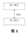
- the fronthaul interface between the first network element and the second network element is as shown in FIG. 1 .
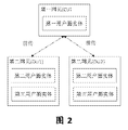
- one of the implementation scenarios is that one first network element connects two or more second network elements. As shown in FIG. 2, the first network element simultaneously sends the data packets of the UE to multiple.
- the second network element which firstly ensures the reliability and transmission efficiency of transmission between the first network element and the second network element, and improves the reliability and transmission efficiency of data transmission between the second network element and the terminal, in FIG. 2
- the synchronization of the data packets transmitted by the two second network elements can be well maintained.
- the embodiment of the present disclosure provides a data packet transmission method and apparatus, to at least solve the problem that the transmission data is not synchronized when a plurality of second network elements send data packets to the terminal in the related art.
- a data packet transmission method including: the first network element generates first indication information according to a transmission state fed back by the second network element to the first network element, where the first indication The information is used to indicate that the second network element that has sent the data packet to the terminal has failed to discard the data packet indicated by the first indication information.
- the method before the first network element generates the first indication information according to the transmission status, includes: The second network element sends a data packet to the terminal; the second network element receives the transmission status of the data packet fed back by the terminal; and the second network element feeds back the transmission status to the first network element.
- the first indication information is used to indicate that the second network element that has sent the data packet to the terminal that has not succeeded to discard the data packet indicated by the first indication information includes at least one of the following: the first indication The information is used to indicate that the second network element that has sent the data packet to the terminal has failed to delete the data packet indicated by the first indication information, where the first indication information is used to indicate that the data packet is sent to the terminal is not successful.
- the second network element sends an empty data packet to the terminal.
- the second indication where the first indication information is used to indicate that the data packet is sent to the terminal, is not sent to the terminal, and the second network element sends the data packet to the terminal.
- the method further includes: the second network element is in the Adding empty packet indication information to the data packet, where the empty packet indication information is used to indicate that the data packet sent to the terminal is a null data packet; and the second network element sends the data packet to the terminal So that the terminal deletes a packet data unit PDU or PDU segment corresponding to the null data packet in the cache.
- the first indication information is further used to indicate a sequence number of the one or more data packets that need to be transmitted by the at least two second network elements.
- the first indication information includes at least one of the following: a sequence number of a data packet, a sequence of data packet sequence numbers, an interval segment of a sequence number corresponding to the data packet, and a plurality of interval segment lists.
- a data packet transmission method including: a second network element receives a data packet sent by a first network element; and a second network element generates a second indication according to a received state of the data packet.
- the second network element sends the second indication information to the first network element, where the second indication information is used to indicate the receiving status of the data packet.
- the second indication information is further used to indicate a sequence number of one or more data packets that need to be transmitted by the second network element.
- the second indication information is transmitted on an interface between the second network element and the first network element.
- a data packet transmission method including: a first network element sends the same data packet to at least two second network elements; and the first network element receives the at least two second The third indication information that is sent by the second network element of the data packet is successfully received by the network element, where the third indication information is used to indicate that the first network element is deleted and not succeeded to the other second network element. And sending, by the first network element, the same data packet that has not been successfully sent to other second network elements in the at least two second network elements according to the third indication information.
- the third indication information is further used to indicate a sequence number of the one or more data packets that need to be transmitted by the at least two second network elements.
- the third indication information is transmitted on an interface between the at least two second network elements and the first network element.
- a data packet transmission apparatus including a triggering module, where the triggering module is configured to trigger a first network element to generate a first according to a transmission state fed back by the second network element to the first network element. Instructing information, wherein the first indication information is used to indicate that the second network element that has sent the data packet to the terminal has not successfully sent the data packet indicated by the first indication information.
- the apparatus further includes: a first sending module, configured to send a data packet to the terminal; a receiving module is configured to receive a transmission state of the data packet fed back by the terminal; the triggering module is further configured to feed back the transmission state to the first network element.
- the first indication information is used to indicate that the second network element that has sent the data packet to the terminal that has not succeeded to discard the data packet indicated by the first indication information includes at least one of the following: the first indication The information is used to indicate that the second network element that has sent the data packet to the terminal has failed to delete the data packet indicated by the first indication information, where the first indication information is used to indicate that the data packet is sent to the terminal is not successful.
- the second network element sends an empty data packet to the terminal.
- the triggering module is further configured to: when the first indication information is used to indicate that the second network element that has sent the data packet to the terminal has not succeeded, send the null data packet to the terminal, and the second network element After the data packet is sent to the terminal is not successful, after the first transmission state is fed back to the first network element and the first network element is triggered to generate the first indication information according to the transmission status, Adding empty packet indication information to the data packet, wherein the empty packet indication information is used to indicate that the data packet sent to the terminal is a null data packet; and the data packet is sent to the terminal, so that the terminal deletes A packet data unit PDU or PDU segment corresponding to the null data packet in the cache.
- the first indication information is further used to indicate a sequence number of the one or more data packets that need to be transmitted by the at least two second network elements.
- the first indication information includes at least one of the following: a sequence number of a data packet, a sequence of data packet sequence numbers, an interval segment of a sequence number corresponding to the data packet, and a plurality of interval segment lists.
- a data packet transmission method including: a second receiving module configured to receive a data packet sent by a first network element; and a generating module configured to receive according to the data packet And generating a second indication information, where the second sending module is configured to send the second indication information to the first network element, where the second indication information is used to indicate a receiving status of the data packet.
- the second indication information is further used to indicate a sequence number of one or more data packets that need to be transmitted by the second network element.
- the second indication information is transmitted on an interface between the second network element and the first network element.
- a data packet transmission apparatus including: a third sending module, configured to send the same data packet to at least two second network elements; and a third receiving module configured to receive The third indication information that is sent by the second network element that successfully receives the data packet in the at least two second network elements, where the third indication information is used to indicate that the first network element is deleted.
- the data packet successfully sent by the other second network element; the deleting module is configured to delete the same data packet that has not been successfully sent to the other second network element in the at least two second network elements according to the third indication information.
- the third indication information is further used to indicate a sequence number of the one or more data packets that need to be transmitted by the at least two second network elements.
- the third indication information is transmitted on an interface between the at least two second network elements and the first network element.
- a storage medium is also provided.
- the storage medium is configured to store program code for performing: the second network element transmitting a data packet to the terminal; the second network element receiving a transmission status of the data packet fed back by the terminal; the second network Transmitting the transmission state to the first network element and triggering the first network element according to the
- the first indication information is generated by the first indication information, where the first indication information is used to indicate that the second network element that has sent the data packet to the terminal has failed to discard the data packet indicated by the first indication information.
- the storage medium is further configured to store program code for performing the following steps: the first indication information is used to indicate that the second network element that has sent the data packet to the terminal has not succeeded to discard the first indication information
- the indicated data packet includes at least one of the following: the first indication information is used to indicate that the second network element that has sent the data packet to the terminal has not successfully deleted the data packet indicated by the first indication information, where the first The indication information is used to indicate that the second network element that has sent the data packet to the terminal has not sent a null data packet to the terminal.
- the storage medium is further configured to store program code for: transmitting, by the second network element, that the first indication information is used to indicate that the data packet is not successfully sent to the terminal, to send the null data packet to the terminal If the second network element sends the data packet to the terminal, the transmission status is fed back to the first network element, and the first network element is triggered to generate the first information according to the transmission status.
- the second network element adds null packet indication information to the data packet, where the null packet indication information is used to indicate that the data packet sent to the terminal is an empty data packet; The second network element sends the data packet to the terminal, so that the terminal deletes a packet data unit PDU or a PDU segment corresponding to the null data packet in the cache.
- the storage medium is further configured to store program code for performing the following steps: the first indication information is further used to indicate a sequence of one or more data packets that need to be transmitted by the at least two second network elements number.
- the storage medium is further configured to store program code for performing the following steps: the first indication information comprises at least one of: a serial number of a data packet, a serial number list of the data packet, and a serial number corresponding to the data packet. Interval segment, multiple segment segment list.
- a storage medium is also provided.
- the storage medium is configured to store program code for performing the following steps: the second network element receives the data packet sent by the first network element; and the second network element generates the second indication information according to the receiving state of the data packet; The second indication information is sent to the first network element, where the second indication information is used to indicate a receiving status of the data packet.
- the storage medium is further configured to store program code for performing the following steps: the second indication information is further used to indicate a sequence number of one or more data packets that need to be transmitted by the second network element.
- the storage medium is further configured to store program code for performing the step of: transmitting the second indication information on an interface between the second network element and the first network element.
- a storage medium is also provided.
- the storage medium is configured to store program code for performing: the first network element transmitting the same data packet to the at least two second network elements; the first network element receiving the successful reception in the at least two second network elements a third indication information that is sent by the second network element of the data packet, where the third indication information is used to indicate that the first network element deletes a data packet that has not been successfully sent to the other second network element; The first network element deletes, according to the third indication information, the same data packet that has not been successfully sent to other second network elements in the at least two second network elements.
- the storage medium is further configured to store program code for performing the following steps: the third indication information is further used to indicate a sequence of one or more data packets that need to be transmitted by the at least two second network elements number.
- the storage medium is further configured to store program code for performing the following steps: the third indication information is in the Transmitting on an interface between the at least two second network elements and the first network element.
- the second network element sends a data packet to the terminal; the second network element receives the transmission status of the data packet fed back by the terminal; the second network element feeds back the transmission status to the first network element and triggers the first network element to generate according to the transmission status.
- the first indication information where the first indication information is used to indicate that the second network element that has sent the data packet to the terminal that has not successfully succeeded discards the data packet indicated by the first indication information.
- the second network element feeds back the transmission status of the transmitted data packet to the first network element, so that the first network element can delete the data packet according to the second network element that does not successfully transmit the data packet according to the transmission status, thereby avoiding successful transmission.
- the second network element of the data packet transmits a new data packet
- the second network element that has not successfully transmitted the data packet is still transmitting the data packet that is not successfully transmitted, so that multiple second network elements can synchronously transmit the data, so that the solution can be solved.
- the problem that the transmission data is not synchronized when a plurality of second network elements send data packets to the terminal ensures synchronization of data transmission between the plurality of second network elements, thereby improving reliability of data transmission.
- FIG. 1 is a schematic diagram of a fronthaul interface between a first network element and a second network element in the related art
- FIG. 2 is a schematic diagram of a first network element connected to a plurality of second network elements in the related art
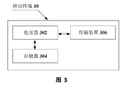
- FIG. 3 is a block diagram showing the hardware structure of a mobile terminal of a data packet transmission method according to an embodiment of the present disclosure
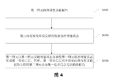
- FIG. 4 is a flowchart 1 of a data packet transmission method according to an embodiment of the present disclosure.
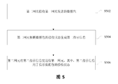
- FIG. 5 is a second flowchart of a data packet transmission method according to an embodiment of the present disclosure.
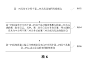
- FIG. 6 is a flowchart 3 of a data packet transmission method according to an embodiment of the present disclosure.
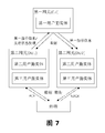
- FIG. 7 is a schematic diagram of a connection structure between a network element and a terminal according to an embodiment of the present disclosure.
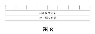
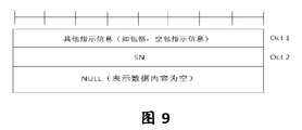
- FIG. 8 is a schematic structural diagram of a PDU frame of first indication information transmitted between a first network element and a second network element according to an embodiment of the present disclosure
- FIG. 9 is a first schematic diagram of a PDU frame structure of a null data packet transmitted between a second network element and a terminal according to an embodiment of the present disclosure
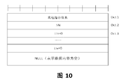
- FIG. 10 is a second schematic diagram of a PDU frame structure of a null data packet transmitted between a second network element and a terminal according to an embodiment of the present disclosure
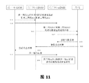
- FIG. 11 is a schematic diagram 1 of a first indication information generation process according to an embodiment of the present application.
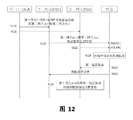
- FIG. 12 is a second schematic diagram of a first indication information generation process according to an embodiment of the present disclosure.
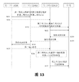
- FIG. 13 is a schematic diagram showing that a data packet is an empty packet by adding a null packet indication information in a data packet according to an embodiment of the present disclosure
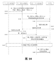
- FIG. 14 is a schematic diagram of telling a terminal that a data packet is a null packet by a control signaling configuration according to an embodiment of the present disclosure
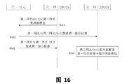
- 16 is a schematic flowchart of an uplink data transmission process according to an embodiment of the present disclosure.
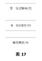
- 17 is a block diagram 1 of a structure of a data packet transmission apparatus according to an embodiment of the present disclosure.
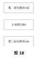
- FIG. 18 is a structural block diagram 2 of a data packet transmission apparatus according to an embodiment of the present disclosure.
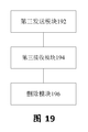
- 19 is a block diagram 3 of a structure of a data packet transmission apparatus according to an embodiment of the present disclosure.
- FIG. 3 is a hardware structural block diagram of a mobile terminal of a data packet transmission method according to an embodiment of the present disclosure.
- the mobile terminal 30 may include one or more (only one shown) processor 302 (the processor 302 may include, but is not limited to, a processing device such as a microprocessor MCU or a programmable logic device FPGA).
- the structure shown in FIG. 3 is merely illustrative and does not limit the structure of the above electronic device.
- the mobile terminal 30 may also include more or fewer components than those shown in FIG. 3, or have a different configuration than that shown in FIG.
- the memory 304 can be configured as a software program and a module for storing application software, such as program instructions/modules corresponding to the data packet transmission method in the embodiment of the present disclosure, and the processor 302 executes by executing a software program and a module stored in the memory 304.
- application software such as program instructions/modules corresponding to the data packet transmission method in the embodiment of the present disclosure
- the processor 302 executes by executing a software program and a module stored in the memory 304.
- Various functional applications and data processing, that is, the above methods are implemented.
- Memory 304 can include high speed random access memory and can also include non-volatile memory, such as one or more magnetic storage devices, flash memory, or other non-volatile solid state memory.
- memory 304 can include memory remotely located relative to processor 302, which can be connected to mobile terminal 30 over a network. Examples of such networks include, but are not limited to, the Internet, intranets, local area networks, mobile communication networks, and combinations thereof.
- Transmission device 306 is arranged to receive or transmit data via a network.
- the network instance described above may include a wireless network provided by a communication provider of the mobile terminal 30.
- transmission device 306 includes a Network Interface Controller (NIC) that can be connected to other network devices through a base station to communicate with the Internet.
- NIC Network Interface Controller
- the transmission device 306 can be a Radio Frequency (RF) module configured to communicate with the Internet wirelessly.
- RF Radio Frequency
- FIG. 4 is a flowchart 1 of a data packet transmission method according to an embodiment of the present disclosure. As shown in FIG. 4, the flow includes the following steps:
- Step S402 the second network element sends a data packet to the terminal.
- Step S404 the second network element receives the transmission status of the data packet fed back by the terminal
- Step S406 The second network element feeds back the transmission status to the first network element, and triggers the first network element to generate the first indication information according to the transmission status, where the first indication information is used to indicate that the data packet sent to the terminal is not yet successful.
- the network element discards the data packet indicated by the first indication information.
- the first network element can delete the data packet by using the second network element that does not successfully transmit the data packet according to the transmission status, thereby avoiding The number of successful transmissions
- the second network element of the packet transmits a new data packet
- the second network element that has not successfully transmitted the data packet is still transmitting the data packet that is not successfully transmitted, so that multiple second network elements can synchronously transmit the data, so that the solution can be solved.
- the problem that the transmission data is not synchronized when a plurality of second network elements send data packets to the terminal ensures synchronization of data transmission between the plurality of second network elements, thereby improving reliability of data transmission.
- the first indication information is used to indicate that the second network element that has sent the data packet to the terminal that has not succeeded to discard the data packet indicated by the first indication information includes at least one of the following: the first indication information is used to indicate that the data is sent to the terminal.
- the second network element that has not succeeded in the packet deletes the data packet indicated by the first indication information, and the first indication information is used to indicate that the second network element that has sent the data packet to the terminal has not sent a null data packet to the terminal.
- the method further includes: adding, by the second network element, empty packet indication information, where the empty packet indication information is used to indicate sending The data packet to the terminal is a null data packet; the second network element sends the data packet to the terminal, so that the terminal deletes a packet data unit (Packet Data Unit, PDU for short) or a PDU segment corresponding to the null data packet in the cache.
- PDU Packet Data Unit
- the first indication information is further used to indicate a sequence number of the one or more data packets that need to be transmitted by the at least two second network elements.
- the first indication information includes at least one of the following: a sequence number of the data packet, a sequence of the data packet sequence number, an interval segment of the sequence number corresponding to the data packet, and a plurality of interval segment lists.
- the first network element generates first indication information according to the state feedback information of the second network element, where the first indication information is used to instruct the second network element to delete the specified data packet.
- the sending status feedback information includes at least one of the following: a transmission status of the second network element data, and a sequence number of the next newly transmitted data packet.
- the first network element may indicate that the other second network element that failed to send the data packet deletes the data packet successfully received by the first network element.
- the information of the empty packet may be notified to the terminal by using control signaling.
- FIG. 5 is a second flowchart of a data packet transmission method according to an embodiment of the present disclosure. As shown in FIG. 5, the flow includes the following steps:
- Step S502 the second network element receives the data packet sent by the first network element.
- Step S504 the second network element generates second indication information according to the receiving state of the data packet
- Step S506 The second network element sends the second indication information to the first network element, where the second indication information is used to indicate the receiving status of the data packet.
- the second network element can feed back the data packet receiving state to the first network element by using the second indication information, so that the first network element can know the transmission state of the data packet, and avoid the first time when the data packet transmission succeeds.
- the network element repeatedly transmits the data packet to ensure the reliability of data transmission between the first network element and the second network element, thereby ensuring the reliability of the second network element transmitting data to the terminal. Therefore, the problem that the transmission data is not synchronized when the data packets are sent to the terminal by the plurality of second network elements in the related art can be solved, the synchronization of the data transmitted between the plurality of second network elements is ensured, and the reliability of the data transmission is improved.
- the second indication information is further used to indicate a sequence number of one or more data packets that need to be transmitted by the second network element.
- the second indication information is transmitted on an interface between the second network element and the first network element.
- FIG. 6 is a third flowchart of a data packet transmission method according to an embodiment of the present disclosure. As shown in FIG. 6, the flow includes the following steps:
- Step S602 the first network element sends the same data packet to the at least two second network elements.
- step S604 the first network element receives the third indication information that is sent by the second network element that successfully receives the data packet in the at least two second network elements, where the third indication information is used to indicate that the first network element is deleted. a data packet successfully sent by another second network element in the two second network elements;
- Step S606 The first network element deletes the same data packet that has not been successfully sent to other second network elements in the at least two second network elements according to the third indication information.
- the second network element that successfully receives the data packet feeds back the first indication information of the data packet for indicating that the second network element has not been successfully sent to the first network element, thereby avoiding successful transmission of the data packet.
- the first network element repeatedly transmits the old data packet, so that when the first network element transmits a new data packet to the second network element that successfully transmits the data packet, the first network element still transmits to the second network element of the unsuccessfully transmitted data packet.
- the old data packet guarantees the synchronization of the data packets transmitted to the terminal.
- the problem that the transmission data is not synchronized when the data packets are sent to the terminal by the plurality of second network elements in the related art can be solved, the synchronization of the data transmitted between the plurality of second network elements is ensured, and the reliability of the data transmission is improved.
- the third indication information is further used to indicate a sequence number of the one or more data packets that need to be transmitted by the at least two second network elements.
- the third indication information is transmitted on an interface between the at least two second network elements and the first network element.
- the method further includes: after the second network element successfully receives the data packet of the first network element, the second network element indicates, by using the fourth indication information, that the first network element deletes the data packet to be sent by the other second network element. .
- the interface between the first network element and the second network element in the foregoing embodiment may be a fronthaul interface.
- the foregoing two methods may be regarded as a sending end and a receiving end respectively, wherein the sending end function includes: generating, discarding or generating an empty data packet of the first indication information, and transmitting the null packet to the receiving end.
- the receiving end function includes: receiving a null data packet, discarding or deleting a PDU or a PDU segment in a buffer corresponding to the null data packet sequence number.
- FIG. 1 is a schematic diagram of a fronthaul interface between a first network element and a second network element in the related art.
- the information exchanges between the first network element and the second network element through the front-end fronthaul interface.
- the fronthaul may be an ideal fronthaul or a non-ideal fronthaul.
- the ideal fronthaul transmission delay is relatively small, such as tens to hundreds of microseconds, and the non-ideal fronthaul transmission delay is relatively large, such as milliseconds.
- the first network element is caused by the distinction between ideal and non-ideal fronthaul.
- the second network element has different functional divisions, that is, in the case of non-ideal fronthaul transmission, the delay-sensitive user plane function, such as the function closely related to scheduling, needs to be placed in the second network element, and the delay requirement is not sensitive.
- Functions such as header compression, encryption, and integrity contain are placed in the first network element to meet the transmission delay requirements.
- FIG. 2 is a schematic diagram of a first network element connected to a plurality of second network elements in the related art.
- the first user plane entity is located in the first network element
- the second user plane entity and the third user plane entity are located in the second network element
- the first network element and the second network element are connected through the fronthaul interface, for example,
- the fronthaul interface for example,
- multiple second network elements are centrally controlled by the first network element, and there is no direct interface between the second network elements.
- the second network element (DU1) and the second network element (DU2) are used to distinguish the two different numbers. Two network elements.
- the first user plane entity function is similar to the Packet Data Convergence Protocol (PDCP) of the LTE system and its function enhancement
- the second user plane entity is similar to the radio link control of the LTE system (Radio Link Control).
- RLC Radio Link Control
- the third user plane entity is similar to the Medium Access Control (MAC) and its function enhancement of the LTE system.
- FIG. 2 only illustrates a case where a first network element is connected to multiple second network elements, and the first network element only includes the first user plane entity, and the second network element only includes the second user plane. Entity and third user plane entity.
- FIG. 7 is a schematic diagram of a connection architecture between a network element and a terminal according to an embodiment of the present disclosure. As shown in FIG. 7, two scenarios are included, one is data packet transmission between the first network element and the second network element, and the other is data packet transmission between the second network element and the terminal, and the first indication is The indication control of information can improve the data transmission efficiency and transmission reliability.
- the first network element sends the same data packet to the two second network elements at the same time, and the second network element (DU1) successfully sends the first indication information to the first network element after successfully receiving the data packet of the first network element.
- the first indication information is used to indicate that the first network element discards or deletes a data packet that is not successfully sent to the second network element (DU2) but has been successfully sent to the second network element (DU1).
- the first indication information is further used to indicate whether the first network element performs data packet retransmission or data packet new transmission.
- the second network element (DU1) sends the transmission status feedback information of the data packet to the terminal to the first network element.
- the first network element generates first indication information according to the state feedback information of the DU1, and instructs the second network element (DU2) to delete the data packet that has been successfully sent to the terminal but the DU2 has not been successfully transmitted by the second network element (DU1).
- the first indication information may be one of the following: a serial number, a serial number list, an interval segment, and a plurality of interval segment lists.
- the second network element transmits the received data packet to the terminal.
- the first network element instructs the second network element (DU2) to discard or delete the data that has not been successfully transmitted according to the sending status feedback information of the second network element to the terminal, so as to reach the second network element (DU1) and the second network.
- the element (DU2) sends the purpose of data synchronization to the terminal.
- FIG. 8 is a schematic diagram of a PDU frame structure of first indication information transmitted between a first network element and a second network element according to an embodiment of the present disclosure.
- the indication information packet may include at least one of the following: data packet type information, data packet length indication information, and a sequence number corresponding to the data packet.
- the first indication information may be one of the following: a serial number, a serial number list, an interval segment, and a plurality of interval segment lists.
- FIG. 9 is a first schematic diagram of a PDU frame structure of a null data packet transmitted between a second network element and a terminal according to an embodiment of the present disclosure.
- the PDU frame structure adopts a frame structure similar to the RLC, and the null packet indication information is added to the PDU header information to indicate that the data content corresponding to the sequence number is empty.
- the PDU header information further includes at least one of the following: segmentation and/or re-segmentation indication information, a sequence number, one or more length indication information, and a segmentation offset.
- FIG. 10 is a second schematic diagram of a PDU frame structure of a null data packet transmitted between a second network element and a terminal according to an embodiment of the present disclosure.
- the PDU frame structure adopts a frame structure similar to that of the RLC, and the PDU header information includes at least one of the following: segmentation and/or re-segment indication information, sequence number, and one or more length indication information. , segmentation offset.
- the length indication information may be set to “0” to indicate that the serial number corresponds to an empty packet.
- FIG. 11 is a first schematic diagram of a first indication information generation process according to an embodiment of the present application.
- This embodiment is to explain how the first indication information is generated, and the related operation after the second network element receives the first indication information.
- the scenario can be applied to a scenario in which the reliability of the data transmission is high and the transmission delay is low.
- an Ultra-Reliable and Low Latency Communications (URLLC) scenario passes through the first network element to the second network.
- the element sends the first indication information to achieve the purpose of synchronizing data transmission between the plurality of second network elements, thereby improving data transmission efficiency.
- the process can include the following steps.
- the first network element CU sends the same data packet to the second network element DU1 and the second network element DU2.
- the first network element and the second network element are connected through the fronthaul interface. , here defined as the "NGx" interface.
- step S112 the second network element DU1 and the second network element DU2 simultaneously transmit the data packet to the terminal.
- the data packet is a complete data packet PDU or PDU segment.
- step S113 the terminal feeds back the unsuccessful feedback information to the second network element DU2, and feeds back the success feedback information to the second network element DU1.
- the terminal feeds back the reception status of the data packet to the second network element DU1 and the second network element DU2, respectively.
- the second network element DU1 reports the transmission status feedback information to the first network element.
- the sending status feedback information includes at least one of the following: a sending status of the second network element data, and a sequence number of the next newly transmitted data packet.
- step S115 the first network element generates first indication information according to the state feedback information of step S114, and sends the first indication information to the second network element DU2.
- the PDU frame structure of the first indication information transmitted between the first network element and the second network element is as shown in FIG. 8.
- the first indication information may be one of the following: a serial number, a serial number list, an interval segment, and a plurality of interval segment lists.
- the first indication information is used to indicate that the second network element deletes the data packet indicated by the first indication information, and/or the first indication information is used to indicate the next newly transmitted data packet sequence of the second network element. number.
- Step S116 The second network element DU2 deletes the specified data packet according to the indication of the first indication information.
- the deleting may be to discard the data packet or set the data packet as an empty packet.
- FIG. 12 is a second schematic diagram of a first indication information generation process according to an embodiment of the present disclosure.
- the difference between FIG. 12 and FIG. 11 is that the terminal generates first indication information according to the receiving state of the second network element data packet, where the first indication information is used to indicate that the second network element deletes and sends the specified data packet.
- the process can include the following steps.
- step S121 the first network element CU simultaneously transmits the same data packet to the second network element DU1 and the second network element DU2.
- step S122 the second network element DU1 and the second network element DU2 send a data packet to the terminal.
- step S123 the terminal generates status feedback information.
- the terminal generates first indication information according to the affirmative determination status information on the successful link, where the first indication information is set to instruct the second network element to delete the data packet indicated by the first indication information.
- the method for generating the state feedback by the terminal includes performing XOR processing on the receiving state of the data on the two links to generate new state feedback information.
- the terminal generates status report information for each link.
- step S124 the terminal sends the first indication information to the second network element DU2, and sends the reception success feedback information to the second network element DU1.
- the PDU frame structure of the first indication information transmitted between the first network element and the second network element is as shown in FIG. 8.
- the first indication information may be one of the following: a serial number, a serial number list, an interval segment, and a plurality of interval segment columns table.
- the first indication information is used to indicate that the second network element deletes the data packet indicated by the first indication information, and/or the first indication information is used to indicate the next newly transmitted data packet of the second network element. serial number.
- the terminal if the terminal receives correctly on a second network element, the terminal sends a positive acknowledgement message to the two second network elements.
- the terminal feeds back the status information according to the respective receiving states, so that the DU that has not been successfully transmitted will perform the retransmission of the data packet.
- the synchronization problem of the data transmission may be solved by the method shown in FIG.
- Step S125 The second network element DU2 deletes the data packet according to the indication of the first indication information.
- the deleting may be to discard the data packet or set the data packet as an empty packet.
- FIG. 13 is a schematic diagram showing that a data packet is an empty packet by adding a null packet indication information in a data packet according to an embodiment of the present disclosure.
- this embodiment is to explain that the second network element adds an empty packet indication to the PDU, and the terminal performs the discarding or deleting operation of the data packet according to the empty packet indication information in the PDU header, and may include the following steps.
- step S131 the first network element CU simultaneously transmits the same data packet to the second network element DU1 and the second network element DU2.
- the first network element and the second network element are connected through a fronthaul interface.
- the term is defined as an "NGx" interface.
- step S132 the second network element DU1 and the second network element DU2 simultaneously transmit the data packet to the terminal.
- the data packet is a complete data packet PDU or PDU segment.
- step S133 the terminal feeds back the unsuccessful feedback information to the second network element DU2, and feeds back the success feedback information to the second network element DU1.
- the terminal feeds back the receiving status of the data packet to the second network element DU1 and the second network element DU2, respectively.
- step S134 the second network element DU1 reports the transmission status feedback information to the first network element.
- the first network element In step S135, the first network element generates first indication information according to the state feedback information of step S134, and sends the first indication information to the second network element DU2.
- the sending status feedback information includes at least one of the following: a sending status of the second network element data, and a sequence number of the next newly transmitted data packet.
- the first indication information may be one of the following: a serial number, a serial number list, an interval segment, and a plurality of interval segment lists.
- the first indication information is used to indicate that the second network element deletes the data packet indicated by the first indication information, and/or the first indication information is used to indicate the next newly transmitted data packet of the second network element. serial number.
- Step S136 The second network element DU2 generates an empty data packet according to the indication of the first indication information.
- the second network element DU2 adds the null packet indication information to the PDU header information, and the PDU frame structure of the null data packet is as shown in FIG. 9.
- the second network element DU2 sets the length indication information in the PDU header to “0”, indicating that the data packet is a null packet, and the PDU frame structure is as shown in FIG. 10 .
- the second network element DU2 discards the data packet indicated by the first indication information according to the indication of the first indication information.
- Step S137 The second network element DU2 sends a null packet to the terminal.
- the terminal after receiving the null packet, deletes the local data PDU or PDU segment corresponding to the null packet sequence number.
- FIG. 14 is a schematic diagram of telling a terminal that a data packet is a null packet by a control signaling configuration according to an embodiment of the present disclosure. 14 is different from FIG. 13 in that the information of the empty packet is notified to the terminal by control signaling, which may include the following steps.
- step S141 the first network element CU simultaneously transmits the same data packet to the second network element DU1 and the second network element DU2.
- the first network element and the second network element are connected through a fronthaul interface.
- the term is defined as an "NGx" interface.
- step S142 the second network element DU1 and the second network element DU2 simultaneously transmit the data packet to the terminal.
- the data packet is a complete data packet PDU or PDU segment.
- step S143 the terminal feeds back the unsuccessful feedback information to the second network element DU2, and feeds back the success feedback information to the second network element DU1.
- the terminal feeds back the receiving status of the data packet to the second network element DU1 and the second network element DU2, respectively.
- step S144 the second network element DU1 reports the transmission status feedback information to the first network element.
- the first network element In step S145, the first network element generates first indication information according to the state feedback information of step S144, and sends the first indication information to the second network element DU2.
- the sending status feedback information includes at least one of the following: a sending status of the second network element data, and a sequence number of the next newly transmitted data packet.
- the first indication information may be one of the following: a serial number, a serial number list, an interval segment, and a plurality of interval segment lists.
- the first indication information is used to indicate that the second network element deletes the data packet indicated by the first indication information, and/or the first indication information is used to indicate the next newly transmitted data packet of the second network element. serial number.
- step S146 the second network element DU2 generates an empty data packet according to the indication of the first indication information.
- the second network element DU2 adds the null packet indication information to the PDU header information, and the PDU frame structure of the null data packet is as shown in FIG. 9.
- the second network element DU2 discards the data packet indicated by the first indication information according to the indication of the first indication information.
- the network element configuration terminal performs reception of an empty packet.
- the configuration information includes at least one of the following: L3 control signaling, L2 control signaling, and L1 control signaling.
- the L3 control signaling may be a Radio Resource Control (RRC) control signaling;
- the L2 control signaling may be a MAC CE;
- the L1 control signaling may be a physical layer control signaling (such as a physical downlink control channel). (Physical Downlink Control Channel, abbreviated as PDCCH) or ePDCCH).
- RRC Radio Resource Control
- PDCCH Physical Downlink Control Channel
- ePDCCH Physical Downlink Control Channel
- step S148 the second network element DU2 sends a null packet to the terminal.
- the terminal after receiving the null packet, deletes the local data PDU or PDU segment corresponding to the null packet sequence number.
- FIG. 15 is a flowchart of a downlink data transmission processing according to an embodiment of the present disclosure.
- the first network element is a CU
- the second network element is a DU
- the interface between the CU and the DU is called an NGx interface
- the NGx-C is a forward interface control plane
- the NGx-U is a forward interface user. surface.
- the embodiment should be configured to send the downlink data of the UE to multiple CUs in the downlink data transmission process. After one of the DUs successfully receives the data of the CU, the CU discards or deletes the CU.
- the second network element (such as DU2) has successfully sent the data packet to the second network element (such as DU1), thereby improving data transmission efficiency.
- the process can include the following steps.
- step S151 the CU sends a "data transmission message" to the DU, and the serial number of the packet to be sent through the NGx-U
- the information tells the DU that the DU saves the information and can be set to detect packet loss on the forward interface.
- the DU After receiving the data packet sent by the CU through the NGx-U, the DU immediately informs the CU that the current data packet has been successfully received by the forward interface by using the first indication information.
- the CU After the CU obtains the notification message in step S153, if the data packet has not been sent yet in other branches, the packet is discarded or replaced with an empty packet. The CU relies on the packet sequence number in step S151 to confirm which packet has been successfully received by the DU.
- FIG. 16 is a schematic flowchart of an uplink data transmission process according to an embodiment of the present disclosure.
- the first network element is a CU
- the second network element is a DU
- the interface between the CU and the DU is called an NGx interface
- the NGx-C is a forward interface control plane
- the NGx-U is a forward interface user. surface.
- the embodiment is applied to the scenario in which the uplink data is sent to the CU by the multiple DUs in the uplink data transmission process.
- the CU instructs the other second network element (such as the DU2) to discard. Or delete the data packets that the CU has successfully received, thereby improving data transmission efficiency.
- the process can include the following steps.
- step S161 the DU sends the uplink data to the CU through the NGx-U.
- the CU After receiving the uplink data packet sent by the certain DU in step S162, the CU notifies the other DUs that provide the data transmission service for the UE, and the current data packet has been successfully received through the forward interface.
- the DU uplink data may also be notified that the data has been successfully received.
- step S163 after receiving the notification, the other DU discards the packet or replaces it with an empty packet.
- the DU relies on the packet sequence number in step S161 to confirm which packet has been successfully received.
- the data packet sequence number herein may be a PDCP SN number or an RLC SN number or a newly defined user plane interface serial number, where the sequence number Sequence Number is simply referred to as SN.
- the method according to the above embodiment can be implemented by means of software plus a necessary general hardware platform, and of course, by hardware, but in many cases, the former is A better implementation.
- the technical solution of the present disclosure which is essential or contributes to the related art, may be embodied in the form of a software product stored in a storage medium (such as ROM/RAM, disk, CD-ROM).
- the instructions include a number of instructions for causing a terminal device (which may be a cell phone, a computer, a server, or a network device, etc.) to perform the methods described in various embodiments of the present disclosure.
- a data packet transmission device is also provided in this embodiment, and the device is configured to implement the foregoing embodiments and preferred embodiments, and details are not described herein.
- the term "module” may implement a combination of software and/or hardware of a predetermined function.
- the apparatus described in the following embodiments is preferably implemented in software, hardware, or a combination of software and hardware, is also possible and contemplated.
- FIG. 17 is a block diagram showing the structure of a data packet transmission apparatus according to an embodiment of the present disclosure. As shown in FIG. 17, the apparatus includes:
- the first sending module 172 is configured to send a data packet to the terminal;
- the first receiving module 174 is connected to the first sending module 172, and is configured to receive a transmission state of the data packet fed back by the terminal;
- the triggering module 176 is connected to the first receiving module 174, and is configured to feed back the transmission status to the first network element and trigger the first network element to generate first indication information according to the transmission status, where the first indication information is used to indicate sending to the terminal.
- the second network element whose data packet has not been successfully discarded discards the data packet indicated by the first indication information.
- the first indication information is used to indicate that the second network element that has sent the data packet to the terminal that has not succeeded to discard the data packet indicated by the first indication information includes at least one of the following: the first indication information is used to indicate that the data is sent to the terminal.
- the second network element that has not succeeded in the packet deletes the data packet indicated by the first indication information, and the first indication information is used to indicate that the second network element that has sent the data packet to the terminal has not sent a null data packet to the terminal.
- the triggering module 176 is further configured to: when the first indication information is used to indicate that the second network element that has sent the data packet to the terminal has not succeeded, send the null data packet to the terminal, and the second network element sends the data packet to the terminal. If the information is sent to the first network element and the first network element is triggered to generate the first indication information according to the transmission status, the empty packet indication information is added to the data packet, where the empty packet indication information is used to indicate the sending.
- the data packet to the terminal is an empty data packet; and the data packet is sent to the terminal, so that the terminal deletes the packet data unit PDU or PDU segment corresponding to the null data packet in the buffer.
- the first indication information is further used to indicate a sequence number of the one or more data packets that need to be transmitted by the at least two second network elements.
- the first indication information includes at least one of the following: a sequence number of the data packet, a sequence of the data packet sequence number, an interval segment of the sequence number corresponding to the data packet, and a plurality of interval segment lists.
- FIG. 18 is a block diagram showing the structure of a data packet transmission apparatus according to an embodiment of the present disclosure.
- the apparatus includes: a second receiving module 182 configured to receive a data packet sent by the first network element; and a generating module 184.
- the second receiving module 182 is configured to generate the second indication information according to the receiving state of the data packet.
- the second sending module 186 is connected to the generating module 184, and configured to send the second indication information to the first network element, where The second indication information is used to indicate a receiving status of the data packet.
- the second indication information is further used to indicate a sequence number of one or more data packets that need to be transmitted by the second network element.
- the second indication information is transmitted on an interface between the second network element and the first network element.
- FIG. 19 is a structural block diagram 3 of a data packet transmission apparatus according to an embodiment of the present disclosure.
- the apparatus includes: a third sending module 192, configured to send the same data packet to at least two second network elements;
- the third receiving module 194 is connected to the third sending module 192, and is configured to receive third indication information that is sent by the second network element that successfully receives the data packet in the at least two second network elements, where the third indication information is used.
- the deleting module 196 is connected to the third receiving module 194, and is configured to delete the other data that has not been sent to the at least two second network elements according to the third indication information.
- each of the above modules may be implemented by software or hardware.
- the foregoing may be implemented by, but not limited to, the foregoing modules are all located in the same processor; or, the above modules are in any combination.
- the forms are located in different processors.
- Embodiments of the present disclosure also provide a storage medium.
- the foregoing storage medium may be configured to store program code for performing the following steps: S1, the second network element sends a data packet to the terminal; and S2, the second network element receives the data fed back by the terminal. a transmission state of the packet; S3, the second network element feeds back the transmission status to the first network element, and triggers the first network element to generate the first indication information according to the transmission status, where the first indication information is used to indicate that the data packet is sent to the terminal. The successful second network element discards the data packet indicated by the first indication information.
- the storage medium is further configured to store program code for performing the following steps: S1, the first indication information is used
- the second network element that indicates that the first network information is discarded by the second network element that has not sent the data packet to the terminal includes at least one of the following: the first indication information is used to indicate that the second network element that the data packet has not been successfully sent to the terminal is sent. Deleting the data packet indicated by the first indication information, where the first indication information is used to indicate that the second network element that has sent the data packet to the terminal has not sent a null data packet to the terminal.
- the storage medium is further configured to store program code for: transmitting, by the first indication information, the second network element that is not successful in transmitting the data packet to the terminal, to the terminal, and sending the null data packet to the terminal and the second After the network element sends the data packet to the terminal, the second network element is in the data after the first network element is sent to the first network element and the first network element is triggered to generate the first indication information according to the transmission status.
- the empty packet indication information is added to the packet, where the empty packet indication information is used to indicate that the data packet sent to the terminal is an empty data packet; S2, the second network element sends the data packet to the terminal, so that the terminal deletes the cached and empty data packets.
- Corresponding packet data unit PDU or PDU segment corresponds the first indication information
- the storage medium is further configured to store program code for performing the following steps: S1, the first indication information is further used to indicate a sequence number of one or more data packets that need to be transmitted by the at least two second network elements .
- the storage medium is further configured to store program code for performing the following steps: S1, the first indication information includes at least one of: a serial number of the data packet, a list of the serial number of the data packet, and a sequence corresponding to the data packet. The interval segment of the number and the list of multiple interval segments.
- Embodiments of the present disclosure also provide a storage medium.
- the foregoing storage medium may be configured to store program code for performing the following steps: S1, the second network element receives the data packet sent by the first network element; S2, the second network element is configured according to The receiving status of the data packet generates the second indication information; S3, the second network element sends the second indication information to the first network element, where the second indication information is used to indicate the receiving status of the data packet.
- the storage medium is further configured to store program code for performing the following steps: S1, the second indication information is further used to indicate a sequence number of the one or more data packets that need to be transmitted by the second network element.
- the storage medium is further arranged to store program code for performing the step of: S1, the second indication information being transmitted on an interface between the second network element and the first network element.
- Embodiments of the present disclosure also provide a storage medium.
- the foregoing storage medium may be configured to store program code for performing the following steps: S1, the first network element sends the same data packet to at least two second network elements; S2, Receiving, by the network element, the third indication information that is sent by the second network element that successfully receives the data packet in the at least two second network elements, where the third indication information is used to indicate that the first network element is deleted from the other second network element The data packet that is successfully sent; S3, the first network element deletes the same data packet that has not been successfully sent to the other second network element in the at least two second network elements according to the third indication information.
- the storage medium is further configured to store program code for performing the following steps: S1, the third indication information is further configured to indicate a sequence number of the one or more data packets that need to be transmitted by the at least two second network elements .
- the storage medium is further arranged to store program code for performing the step of: S1, the third indication information being transmitted on an interface between the at least two second network elements and the first network element.
- the foregoing storage medium may include, but not limited to, a USB flash drive, a Read-Only Memory (ROM), a Random Access Memory (RAM), a mobile hard disk, and a magnetic memory.
- ROM Read-Only Memory
- RAM Random Access Memory
- a mobile hard disk e.g., a hard disk
- magnetic memory e.g., a hard disk
- the processor is configured to: according to the stored program code in the storage medium, the second network element sends a data packet to the terminal; and the second network element receives the data packet that is fed back by the terminal. Transmitting a state of the second network element to the first network element and triggering the first network element to generate first indication information according to the transmission status, where the first indication information is used to indicate a direction The second network element that the terminal sends the data packet has not succeeded, and discards the data packet indicated by the first indication information.
- the processor performs, according to the stored program code in the storage medium, the first indication information is used to indicate that the second network element that has sent the data packet to the terminal has not been successfully discarded.
- the data packet indicated by the first indication information includes at least one of the following: the first indication information is used to indicate that the second network element that has sent the data packet to the terminal has not successfully deleted the data packet indicated by the first indication information, The first indication information is used to indicate that the second network element that has sent the data packet to the terminal has not sent a null data packet to the terminal.
- the processor performs, according to the stored program code in the storage medium, the second indication, where the first indication information is used to indicate that the data packet is not successfully sent to the terminal, to the terminal.
- Sending a null data packet and if the second network element sends the data packet to the terminal, the transmission state is fed back to the first network element, and the first network element is triggered according to the transmission.
- the second network element adds null packet indication information to the data packet, where the null packet indication information is used to indicate that the data packet sent to the terminal is empty. a data packet; the second network element sends the data packet to the terminal, so that the terminal deletes a packet data unit PDU or a PDU segment corresponding to the null data packet in the cache.
- the processor is executed according to the stored program code in the storage medium: the first indication information is further used to indicate that one or more of the at least two second network elements need to be transmitted.
- the serial number of the packet is the serial number of the packet.
- the processor is executed according to the stored program code in the storage medium: the first indication information includes at least one of the following: a serial number of the data packet, a serial number list of the data packet, and a data packet. The interval segment of the corresponding serial number and the list of multiple interval segments.
- the processor executes, according to the stored program code in the storage medium, the second network element receives the data packet sent by the first network element, and the second network element generates the data packet according to the received state of the data packet.
- the second indication information is sent by the second network element to the first network element, where the second indication information is used to indicate the receiving status of the data packet.
- the processor is executed according to the stored program code in the storage medium: the second indication information is further used to indicate that the second network element has one or more data packets that need to be transmitted. serial number.
- the processor performs, according to the stored program code in the storage medium, the second indication information is transmitted on an interface between the second network element and the first network element.
- the processor is configured to: according to the stored program code in the storage medium, the first network element sends the same data packet to the at least two second network elements; the first network element receives the at least two The third indication information that is received by the second network element of the data packet is successfully received by the second network element, where the third indication information is used to indicate that the first network element is deleted from the other second The data packet successfully sent by the network element; the first network element deletes the same data packet that has not been successfully sent to the other second network element in the at least two second network elements according to the third indication information.
- the processor executes according to the stored program code in the storage medium: the third indication
- the information is further used to indicate a sequence number of the one or more data packets that need to be transmitted by the at least two second network elements.
- the processor performs, according to the stored program code in the storage medium, an interface between the at least two second network elements and the first network element. Transfer on.
- modules or steps of the present disclosure described above can be implemented by a general-purpose computing device that can be centralized on a single computing device or distributed across a network of multiple computing devices. Alternatively, they may be implemented by program code executable by the computing device such that they may be stored in the storage device by the computing device and, in some cases, may be different from the order herein.
- the steps shown or described are performed, or they are separately fabricated into individual integrated circuit modules, or a plurality of modules or steps thereof are fabricated as a single integrated circuit module. As such, the disclosure is not limited to any specific combination of hardware and software.
Landscapes
- Engineering & Computer Science (AREA)
- Computer Networks & Wireless Communication (AREA)
- Signal Processing (AREA)
- Computer Security & Cryptography (AREA)
- Quality & Reliability (AREA)
- Mobile Radio Communication Systems (AREA)
Abstract
Description
Claims (25)
- 一种数据包传输方法,包括:第一网元根据第二网元向第一网元反馈的传输状态生成第一指示信息,其中,所述第一指示信息用于指示向终端发送数据包还未成功的第二网元丢弃所述第一指示信息指示的数据包。
- 根据权利1所述的方法,其中,所述第一网元根据所述传输状态生成第一指示信息之前包括:所述第二网元向所述终端发送数据包;所述第二网元接收所述终端反馈的所述数据包的传输状态;所述第二网元向所述第一网元反馈所述传输状态。
- 根据权利要求1所述的方法,其中,所述第一指示信息用于指示向所述终端发送数据包还未成功的第二网元丢弃所述第一指示信息指示的数据包包括以下至少之一:所述第一指示信息用于指示向所述第二网元删除所述第一指示信息指示的数据包,所述第一指示信息用于指示第二网元向所述终端发送空数据包。
- 根据权利要求3所述的方法,其中,在所述第一指示信息用于指示所述第二网元向所述终端发送空数据包且所述第二网元向所述终端发送数据包还未成功的情况下,在向所述第一网元反馈所述传输状态并触发所述第一网元根据所述传输状态生成第一指示信息之后,还包括:所述第二网元在所述数据包中增加空包指示信息,其中,所述空包指示信息用于指示发送给所述终端的数据包是空数据包;所述第二网元将所述数据包发送给所述终端,以便所述终端删除缓存中与所述空数据包对应的分组数据单元PDU或PDU分段。
- 根据权利要求1所述的方法,其中,所述第一指示信息还用于指示所述第二网元下一个或多个需要传输的数据包的序列号。
- 根据权利要求1至5中任一项所述的方法,其中,所述第一指示信息包括以下至少之一:一个数据包的序列号、数据包序列号列表、数据包对应的序列号的区间段、多个区间段列表。
- 一种数据包传输方法,包括:第二网元接收第一网元发送的数据包;第二网元根据所述数据包的接收状态生成第二指示信息;第二网元将所述第二指示信息发送给第一网元,其中,所述第二指示信息用于指示所述数据包的接收状态。
- 根据权利要求7所述的方法,其中,所述第二指示信息还用于指示所述第二网元下一个或多个需要传输的数据包的序列号。
- 根据权利要求7或者8所述的方法,其中,所述第二指示信息在所述第二网元与所 述第一网元之间的接口上传输。
- 一种数据包传输方法,包括:第一网元向至少两个第二网元发送相同的数据包;第一网元接收所述至少两个第二网元中成功接收所述数据包的第二网元反馈的第三指示信息,其中,所述第三指示信息用于指示所述第一网元删除还未向所述至少两个第二网元中其他第二网元成功发送的数据包;第一网元根据所述第三指示信息删除还未向所述至少两个第二网元中其他第二网元成功发送的相同的数据包。
- 根据权利要求10所述的方法,其中,所述第三指示信息还用于指示所述至少两个第二网元下一个或多个需要传输的数据包的序列号。
- 根据权利要求10或者11所述的方法,其中,所述第三指示信息在所述至少两个第二网元与所述第一网元之间的接口上传输。
- 一种数据包传输装置,包括触发模块,所述触发模块设置为触发第一网元根据第二网元向第一网元反馈的传输状态生成第一指示信息,其中,所述第一指示信息用于指示向终端发送数据包还未成功的所述第二网元丢弃所述第一指示信息指示的数据包。
- 根据权利要求13所述的装置,还包括:第一发送模块,设置为向所述终端发送数据包;第一接收模块,设置为接收所述终端反馈的所述数据包的传输状态;所述触发模块还设置为向所述第一网元反馈所述传输状态。
- 根据权利要求13中所述的装置,其中,所述第一指示信息用于指示向所述终端发送数据包还未成功的第二网元丢弃所述第一指示信息指示的数据包包括以下至少之一:所述第一指示信息用于指示向所述终端发送数据包还未成功的第二网元删除所述第一指示信息指示的数据包,所述第一指示信息用于指示向所述终端发送数据包还未成功的第二网元向所述终端发送空数据包。
- 根据权利要求15所述的装置,其中,所述触发模块,还设置为在所述第一指示信息用于指示向终端发送数据包还未成功的第二网元向所述终端发送空数据包且所述第二网元向所述终端发送数据包还未成功的情况下,在向所述第一网元反馈所述传输状态并触发所述第一网元根据所述传输状态生成第一指示信息之后,在所述数据包中增加空包指示信息,其中,所述空包指示信息用于指示发送给所述终端的数据包是空数据包;以及将所述数据包发送给所述终端,以便所述终端删除缓存中与所述空数据包对应的分组数据单元PDU或PDU分段。
- 根据权利要求13所述的装置,其中,所述第一指示信息还用于指示所述第二网元下一个或多个需要传输的数据包的序列号。
- 根据权利要求13至17中任一项所述的装置,其中,所述第一指示信息包括以下至少之一:一个数据包的序列号、数据包序列号列表、数据包对应的序列号的区间段、多 个区间段列表。
- 一种数据包传输装置,包括:第二接收模块,设置为接收第一网元发送的数据包;生成模块,设置为根据所述数据包的接收状态生成第二指示信息;第二发送模块,设置为将所述第二指示信息发送给第一网元,其中,所述第二指示信息用于指示所述数据包的接收状态。
- 根据权利要求19所述的装置,其中,所述第二指示信息还用于指示第二网元下一个或多个需要传输的数据包的序列号。
- 根据权利要求19或者20所述的装置,其中,所述第二指示信息在所述第二网元与所述第一网元之间的接口上传输。
- 一种数据包传输装置,包括:第三发送模块,设置为向至少两个第二网元发送相同的数据包;第三接收模块,设置为接收所述至少两个第二网元中成功接收所述数据包的第二网元反馈的第三指示信息,其中,所述第三指示信息用于指示删除还未向所述至少两个第二网元中其他第二网元成功发送的数据包;删除模块,设置为根据所述第三指示信息删除还未向所述至少两个第二网元中其他第二网元成功发送的相同的数据包。
- 根据权利要求22所述的装置,其中,所述第三指示信息还用于指示所述至少两个第二网元下一个或多个需要传输的数据包的序列号。
- 根据权利要求22或者23所述的装置,其中,所述第三指示信息在所述至少两个第二网元与所述第一网元之间的接口上传输。
- 一种计算机存储介质,所述计算机存储介质存储有执行指令,所述执行指令设置为执行权利要求1至12中任一项所述的方法。
Priority Applications (5)
| Application Number | Priority Date | Filing Date | Title |
|---|---|---|---|
| CA3049285A CA3049285C (en) | 2017-01-10 | 2017-12-22 | Data packet transmission method and device |
| AU2017392542A AU2017392542B2 (en) | 2017-01-10 | 2017-12-22 | Data packet transmission method and device |
| EP17891314.1A EP3570631B1 (en) | 2017-01-10 | 2017-12-22 | Data packet transmission method and device |
| US16/443,861 US10560226B2 (en) | 2017-01-10 | 2019-06-17 | Data packet synchronization |
| US16/786,985 US11206106B2 (en) | 2017-01-10 | 2020-02-10 | Data packet synchronization |
Applications Claiming Priority (2)
| Application Number | Priority Date | Filing Date | Title |
|---|---|---|---|
| CN201710018676.7A CN108289007B (zh) | 2017-01-10 | 2017-01-10 | 数据包传输方法及装置 |
| CN201710018676.7 | 2017-01-10 |
Related Child Applications (1)
| Application Number | Title | Priority Date | Filing Date |
|---|---|---|---|
| US16/443,861 Continuation US10560226B2 (en) | 2017-01-10 | 2019-06-17 | Data packet synchronization |
Publications (1)
| Publication Number | Publication Date |
|---|---|
| WO2018130059A1 true WO2018130059A1 (zh) | 2018-07-19 |
Family
ID=62831385
Family Applications (1)
| Application Number | Title | Priority Date | Filing Date |
|---|---|---|---|
| PCT/CN2017/117881 Ceased WO2018130059A1 (zh) | 2017-01-10 | 2017-12-22 | 数据包传输方法及装置 |
Country Status (6)
| Country | Link |
|---|---|
| US (2) | US10560226B2 (zh) |
| EP (1) | EP3570631B1 (zh) |
| CN (1) | CN108289007B (zh) |
| AU (1) | AU2017392542B2 (zh) |
| CA (1) | CA3049285C (zh) |
| WO (1) | WO2018130059A1 (zh) |
Families Citing this family (12)
| Publication number | Priority date | Publication date | Assignee | Title |
|---|---|---|---|---|
| CN112913277B (zh) * | 2018-11-02 | 2023-03-21 | 中兴通讯股份有限公司 | 数据传输与测量技术 |
| US11743174B2 (en) | 2019-01-29 | 2023-08-29 | Cisco Technology, Inc. | Supporting asynchronous packet operations in a deterministic network |
| US10833987B2 (en) * | 2019-01-29 | 2020-11-10 | Cisco Technology, Inc. | Supporting asynchronous packet operations in a deterministic network |
| WO2020165485A1 (en) * | 2019-02-11 | 2020-08-20 | Nokia Technologies Oy | Apparatus, method and computer program for ue cell selection control in non-terrestial networks |
| CN111698787B (zh) * | 2019-03-14 | 2023-03-31 | 华为技术有限公司 | 调度规则确定方法及其装置 |
| CN112752227B (zh) * | 2019-10-30 | 2023-06-27 | 华为技术有限公司 | 一种通信方法及装置 |
| CN114698149A (zh) * | 2020-01-21 | 2022-07-01 | 华为技术有限公司 | 一种数据传输方法及设备 |
| EP4132085A4 (en) * | 2020-04-23 | 2023-05-24 | Huawei Technologies Co., Ltd. | COMMUNICATION METHOD AND APPARATUS |
| CN111555855B (zh) * | 2020-05-22 | 2022-11-11 | 乐鑫信息科技(上海)股份有限公司 | 一种无线传输方法和装置 |
| JP7644224B2 (ja) * | 2020-09-18 | 2025-03-11 | 深▲ジェン▼引望智能技術有限公司 | ラインコーディング方法および装置 |
| CN114765690B (zh) * | 2020-12-31 | 2023-09-12 | 华为技术有限公司 | 数据包传输方法、通信装置及存储介质 |
| CN116097632A (zh) * | 2022-09-29 | 2023-05-09 | 北京小米移动软件有限公司 | 一种发送数据包的方法、装置、电子设备及可读存储介质 |
Citations (4)
| Publication number | Priority date | Publication date | Assignee | Title |
|---|---|---|---|---|
| US20070140151A1 (en) * | 2005-12-21 | 2007-06-21 | Zriny Donald P | Discarded packet indicator |
| CN103051557A (zh) * | 2012-12-27 | 2013-04-17 | 华为技术有限公司 | 数据流处理方法及系统、控制器、交换设备 |
| CN103797743A (zh) * | 2011-11-04 | 2014-05-14 | 瑞典爱立信有限公司 | 在通信系统中处理冗余数据 |
| CN105519058A (zh) * | 2014-11-10 | 2016-04-20 | 华为技术有限公司 | 控制器、服务节点和数据包转发方法 |
Family Cites Families (13)
| Publication number | Priority date | Publication date | Assignee | Title |
|---|---|---|---|---|
| US6922393B2 (en) * | 2001-01-10 | 2005-07-26 | Asustek Computer Inc. | Data discarding request acknowledgement in a wireless communications protocol |
| US8605642B2 (en) * | 2005-07-07 | 2013-12-10 | Telefonaktiebolaget Lm Ericsson (Publ) | Method and arrangement for coding and scheduling in packet data communication systems |
| US9923995B1 (en) * | 2010-02-27 | 2018-03-20 | Sitting Man, Llc | Methods, systems, and computer program products for sharing information for detecting an idle TCP connection |
| CN102237989B (zh) * | 2010-05-04 | 2015-08-12 | 中兴通讯股份有限公司 | 一种数据传输的方法及系统 |
| CN102724703B (zh) * | 2011-03-30 | 2016-08-03 | 华为技术有限公司 | 数据传输方法以及系统 |
| CN103326832B (zh) * | 2012-03-19 | 2017-11-24 | 华为技术有限公司 | 数据包发送方法、参数配置方法及装置 |
| WO2014082270A1 (zh) * | 2012-11-29 | 2014-06-05 | 华为技术有限公司 | 一种数据传输的控制方法、装置及系统 |
| WO2014139588A1 (en) * | 2013-03-15 | 2014-09-18 | Nokia Solutions And Networks Oy | Coordinated multipoint joint transmission with relaxed backhaul requirements |
| CN104080121B (zh) * | 2013-03-26 | 2019-04-26 | 中兴通讯股份有限公司 | 一种传输数据的方法及系统 |
| US11432223B2 (en) * | 2015-07-08 | 2022-08-30 | Nokia Solutions And Networks Oy | Methods and apparatuses for selecting a first base station or a second base station to transmit a packet data unit (PDU) to a user equipment (UE) |
| US10148582B2 (en) * | 2016-05-24 | 2018-12-04 | Samsung Electronics Co., Ltd. | Managing buffers for rate pacing |
| CN108023683B (zh) * | 2016-11-02 | 2020-12-25 | 华为技术有限公司 | 一种发送报文的方法、装置、芯片及终端 |
| WO2019031924A1 (en) * | 2017-08-10 | 2019-02-14 | Samsung Electronics Co., Ltd. | METHOD AND APPARATUS FOR DATA PROCESSING IN A WIRELESS COMMUNICATION SYSTEM |
-
2017
- 2017-01-10 CN CN201710018676.7A patent/CN108289007B/zh active Active
- 2017-12-22 AU AU2017392542A patent/AU2017392542B2/en active Active
- 2017-12-22 EP EP17891314.1A patent/EP3570631B1/en active Active
- 2017-12-22 WO PCT/CN2017/117881 patent/WO2018130059A1/zh not_active Ceased
- 2017-12-22 CA CA3049285A patent/CA3049285C/en active Active
-
2019
- 2019-06-17 US US16/443,861 patent/US10560226B2/en active Active
-
2020
- 2020-02-10 US US16/786,985 patent/US11206106B2/en active Active
Patent Citations (4)
| Publication number | Priority date | Publication date | Assignee | Title |
|---|---|---|---|---|
| US20070140151A1 (en) * | 2005-12-21 | 2007-06-21 | Zriny Donald P | Discarded packet indicator |
| CN103797743A (zh) * | 2011-11-04 | 2014-05-14 | 瑞典爱立信有限公司 | 在通信系统中处理冗余数据 |
| CN103051557A (zh) * | 2012-12-27 | 2013-04-17 | 华为技术有限公司 | 数据流处理方法及系统、控制器、交换设备 |
| CN105519058A (zh) * | 2014-11-10 | 2016-04-20 | 华为技术有限公司 | 控制器、服务节点和数据包转发方法 |
Non-Patent Citations (1)
| Title |
|---|
| See also references of EP3570631A4 * |
Also Published As
| Publication number | Publication date |
|---|---|
| EP3570631A1 (en) | 2019-11-20 |
| US11206106B2 (en) | 2021-12-21 |
| EP3570631A4 (en) | 2020-01-15 |
| US20200252164A1 (en) | 2020-08-06 |
| AU2017392542B2 (en) | 2020-09-03 |
| US10560226B2 (en) | 2020-02-11 |
| AU2017392542A1 (en) | 2019-07-25 |
| EP3570631B1 (en) | 2022-08-24 |
| CN108289007B (zh) | 2022-04-15 |
| US20190305892A1 (en) | 2019-10-03 |
| CA3049285C (en) | 2021-09-28 |
| CN108289007A (zh) | 2018-07-17 |
| CA3049285A1 (en) | 2018-07-19 |
Similar Documents
| Publication | Publication Date | Title |
|---|---|---|
| US11658722B2 (en) | Method and apparatus for managing user plane operation in wireless communication system | |
| EP3565367B1 (en) | Method for reporting multi-connection transmission capability and ue | |
| EP3570631B1 (en) | Data packet transmission method and device | |
| CN102939729B (zh) | 移动通信系统和移动通信系统中的分组控制方法 | |
| CN107211311B (zh) | 终端及通信系统 | |
| WO2019153517A1 (zh) | 无线链路失败处理方法及相关产品 | |
| KR20140088177A (ko) | 비액세스 계층 재송신의 전달 통지를 위한 방법 및 장치 | |
| CN101385375A (zh) | 用于为切换而配置链路层实体的技术 | |
| CN112187414B (zh) | 指示数据传输情况的方法和装置 | |
| US12166586B2 (en) | Methods, apparatuses, and media for operating point-to-multipoint radio bearer | |
| US20190288770A1 (en) | Apparatuses and methods for using arq processes in a relay device | |
| CN107172649A (zh) | 一种数据传输方法及设备 | |
| WO2023061339A1 (zh) | 一种数据传输方法及通信装置 | |
| CN116349290A (zh) | 通信控制方法 | |
| JP2019527503A (ja) | データ再送の方法及び装置 | |
| CN114630283B (zh) | 多播业务的确认模式传输方法、装置、设备及存储介质 | |
| CN102238657A (zh) | 切换处理方法、装置和系统 | |
| TW202428053A (zh) | 通信方法及裝置 | |
| TW202537326A (zh) | 用於無線電鏈路控制的輪詢改進 | |
| CN121666842A (zh) | 非接入层同步 | |
| WO2024199031A1 (zh) | 通信方法与通信装置 | |
| CN116530201A (zh) | 逻辑信道聚合的方法和装置 |
Legal Events
| Date | Code | Title | Description |
|---|---|---|---|
| 121 | Ep: the epo has been informed by wipo that ep was designated in this application |
Ref document number: 17891314 Country of ref document: EP Kind code of ref document: A1 |
|
| ENP | Entry into the national phase |
Ref document number: 3049285 Country of ref document: CA |
|
| NENP | Non-entry into the national phase |
Ref country code: DE |
|
| ENP | Entry into the national phase |
Ref document number: 2017392542 Country of ref document: AU Date of ref document: 20171222 Kind code of ref document: A |
|
| ENP | Entry into the national phase |
Ref document number: 2017891314 Country of ref document: EP Effective date: 20190812 |