WO2018135306A1 - サポートビーム - Google Patents
サポートビーム Download PDFInfo
- Publication number
- WO2018135306A1 WO2018135306A1 PCT/JP2018/000018 JP2018000018W WO2018135306A1 WO 2018135306 A1 WO2018135306 A1 WO 2018135306A1 JP 2018000018 W JP2018000018 W JP 2018000018W WO 2018135306 A1 WO2018135306 A1 WO 2018135306A1
- Authority
- WO
- WIPO (PCT)
- Prior art keywords
- predetermined direction
- wall portion
- main body
- stabilizer member
- support beam
- Prior art date
- Legal status (The legal status is an assumption and is not a legal conclusion. Google has not performed a legal analysis and makes no representation as to the accuracy of the status listed.)
- Ceased
Links
Images


Classifications
-
- B—PERFORMING OPERATIONS; TRANSPORTING
- B60—VEHICLES IN GENERAL
- B60G—VEHICLE SUSPENSION ARRANGEMENTS
- B60G11/00—Resilient suspensions characterised by arrangement, location or kind of springs
- B60G11/26—Resilient suspensions characterised by arrangement, location or kind of springs having fluid springs only, e.g. hydropneumatic springs
- B60G11/27—Resilient suspensions characterised by arrangement, location or kind of springs having fluid springs only, e.g. hydropneumatic springs wherein the fluid is a gas
-
- B—PERFORMING OPERATIONS; TRANSPORTING
- B60—VEHICLES IN GENERAL
- B60B—VEHICLE WHEELS; CASTORS; AXLES FOR WHEELS OR CASTORS; INCREASING WHEEL ADHESION
- B60B35/00—Axle units; Parts thereof ; Arrangements for lubrication of axles
- B60B35/004—Mounting arrangements for axles
- B60B35/006—Mounting arrangements for axles with mounting plates or consoles fitted to axles
- B60B35/007—Mounting arrangements for axles with mounting plates or consoles fitted to axles for mounting suspension elements to axles
-
- B—PERFORMING OPERATIONS; TRANSPORTING
- B60—VEHICLES IN GENERAL
- B60G—VEHICLE SUSPENSION ARRANGEMENTS
- B60G21/00—Interconnection systems for two or more resiliently-suspended wheels, e.g. for stabilising a vehicle body with respect to acceleration, deceleration or centrifugal forces
- B60G21/02—Interconnection systems for two or more resiliently-suspended wheels, e.g. for stabilising a vehicle body with respect to acceleration, deceleration or centrifugal forces permanently interconnected
- B60G21/04—Interconnection systems for two or more resiliently-suspended wheels, e.g. for stabilising a vehicle body with respect to acceleration, deceleration or centrifugal forces permanently interconnected mechanically
- B60G21/05—Interconnection systems for two or more resiliently-suspended wheels, e.g. for stabilising a vehicle body with respect to acceleration, deceleration or centrifugal forces permanently interconnected mechanically between wheels on the same axle but on different sides of the vehicle, i.e. the left and right wheel suspensions being interconnected
- B60G21/055—Stabiliser bars
-
- B—PERFORMING OPERATIONS; TRANSPORTING
- B60—VEHICLES IN GENERAL
- B60G—VEHICLE SUSPENSION ARRANGEMENTS
- B60G9/00—Resilient suspensions of a rigid axle or axle housing for two or more wheels
- B60G9/04—Resilient suspensions of a rigid axle or axle housing for two or more wheels the axle or housing not being pivotally mounted on the vehicle
-
- B—PERFORMING OPERATIONS; TRANSPORTING
- B60—VEHICLES IN GENERAL
- B60G—VEHICLE SUSPENSION ARRANGEMENTS
- B60G2202/00—Indexing codes relating to the type of spring, damper or actuator
- B60G2202/10—Type of spring
- B60G2202/15—Fluid spring
- B60G2202/152—Pneumatic spring
- B60G2202/1524—Pneumatic spring with two air springs per wheel, arranged before and after the wheel axis
-
- B—PERFORMING OPERATIONS; TRANSPORTING
- B60—VEHICLES IN GENERAL
- B60G—VEHICLE SUSPENSION ARRANGEMENTS
- B60G2204/00—Indexing codes related to suspensions per se or to auxiliary parts
- B60G2204/10—Mounting of suspension elements
- B60G2204/14—Mounting of suspension arms
- B60G2204/148—Mounting of suspension arms on the unsprung part of the vehicle, e.g. wheel knuckle or rigid axle
-
- B—PERFORMING OPERATIONS; TRANSPORTING
- B60—VEHICLES IN GENERAL
- B60G—VEHICLE SUSPENSION ARRANGEMENTS
- B60G2206/00—Indexing codes related to the manufacturing of suspensions: constructional features, the materials used, procedures or tools
- B60G2206/01—Constructional features of suspension elements, e.g. arms, dampers, springs
- B60G2206/50—Constructional features of wheel supports or knuckles, e.g. steering knuckles, spindle attachments
Definitions
- One aspect of the present invention relates to a support beam for supporting an axle housing of a vehicle.
- Patent Document 1 discloses a support beam including a plate-like main body portion extending along a predetermined direction and a protruding portion protruding in an orthogonal direction perpendicular to the predetermined direction from an intermediate portion of the main body portion in the predetermined direction.
- the main body portion is provided at an intermediate portion of the main body portion, and is provided at an axle housing support portion used for supporting the axle housing, and one end portion and the other end portion of the main body portion in a predetermined direction, A pair of suspension member coupling portions coupled to the suspension member.
- the protrusion has a stabilizer member attaching portion to which the stabilizer member is attached.
- the stabilizer member attachment portion is continuous with the main body portion and has a lump shape.
- the stabilizer member mounting portion In the state where the support beam as described above is mounted on the vehicle, the stabilizer member mounting portion is positioned in the vicinity of the brake portion provided on the wheel. Therefore, for example, when removing the brake part for maintenance or the like, the stabilizer member attaching part may interfere with the components of the brake part. In order to avoid this interference, it may be possible to remove the support beam in advance before removing the brake part, but it is necessary to remove the support beam every time the brake part is removed. Workability of work will be reduced. In particular, when an air disc brake is employed in the brake portion, interference is likely to occur between the stabilizer member mounting portion and the slide pin and mounting bolt that are components of the air disc brake.
- An object of one aspect of the present invention is to provide a support beam that can suppress interference between the stabilizer member mounting portion and the components of the brake portion.
- a support beam includes a main body extending along a predetermined direction, and a protrusion protruding in an orthogonal direction perpendicular to the predetermined direction from an intermediate portion of the main body in the predetermined direction.
- the part is provided at an intermediate part of the main body part, and is provided at an axle housing support part used for supporting the axle housing and at one end part and the other end part of the main body part in a predetermined direction, and is connected to the suspension member.
- a suspension member connecting portion, and the protruding portion has a stabilizer member attaching portion to which the stabilizer member is attached, and the stabilizer member attaching portion is continuous with the main body portion and extends along a predetermined direction.
- a bottom wall portion that is continuous with the main body portion and extends along a predetermined direction
- a side wall portion that is continuous with the bottom wall portion and extends along a direction orthogonal to both the predetermined direction and the orthogonal direction
- the stabilizer member mounting portion includes a top wall portion that is continuous with the side wall portion and extends to face the bottom wall portion.
- the side wall portion and the top wall portion may be continuous with the main body portion.
- the rigidity of the stabilizer member mounting portion can be increased, and as a result, the rigidity of the entire support beam can be increased.
- the side wall portion may be provided with an opening in which a part of the stabilizer member is disposed.
- a part of the stabilizer member can be disposed in the opening of the side wall portion, and the stabilizer member can be attached to the stabilizer member attachment portion.
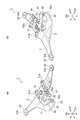
- FIG. 1A is a perspective view of a support beam according to an embodiment as viewed from one side in a predetermined direction
- FIG. 1B is a perspective view of the support beam as viewed from the other side in a predetermined direction
- FIG. 2 is a diagram illustrating a positional relationship between the stabilizer member mounting portion and the brake portion.
- FIG. 3A is a perspective view of the support beam of the comparative example viewed from one side in a predetermined direction
- FIG. 3B is a perspective view of the support beam of the comparative example viewed from the other side in the predetermined direction.
- a support beam 1 shown in FIG. 1 is disposed on a rear wheel portion of a vehicle such as a truck, and is used to support an axle housing.
- the axle housing is a shaft support member that rotatably holds the axle (here, the rear wheel shaft).
- the support beam 1 includes a main body 2 extending along a predetermined direction D1, and a protrusion 3 protruding in an orthogonal direction D2 orthogonal to the predetermined direction D1 from an intermediate portion of the main body 2 in the predetermined direction D1. Yes.
- the support beam 1 is integrally formed of, for example, metal.
- the main body 2 is connected to an axle housing support portion 21 provided at an intermediate portion of the main body 2 in the predetermined direction D1, and a pair of suspension members provided at one end and the other end of the main body 2 in the predetermined direction D1.
- Part 22. Portions other than the axle housing support portion 21 of the main body 2 are plate-shaped.
- the axle housing support portion 21 is a portion for supporting the axle housing.
- the axle housing support portion 21 is thicker than other portions of the main body portion 2 in order to ensure rigidity.
- the axle housing support portion 21 is provided with, for example, a screw hole 21a, and the axle housing is fixed to the axle housing support portion 21 by screwing a bolt into the screw hole 21a.
- the suspension member connecting portion 22 is a portion connected to the suspension member.
- the suspension member is a member constituting a suspension mechanism of the vehicle, and is an air spring, for example.
- the suspension member connecting portion 22 has, for example, a substantially circular shape in plan view (viewed from a direction D3 orthogonal to both the predetermined direction D1 and the orthogonal direction D2).
- Each suspension member connecting portion 22 is provided with a screw hole 22a, for example, and the suspension member connecting portion 22 is connected to the suspension member by screwing a bolt into the screw hole 22a.
- the protruding portion 3 extends in the predetermined direction D1 between the axle housing support portion 21 and an intermediate portion between the axle housing support portion 21 and one suspension member connecting portion 22.
- the protruding portion 3 has a stabilizer member attaching portion 31 on the other suspension member connecting portion 22 side (one side in the predetermined direction D1).
- a stabilizer member is attached to the stabilizer member attachment portion 31.
- the stabilizer member is a member for suppressing rolling of the vehicle.
- the stabilizer member is a stabilizer that also functions as a stabilizer and a torque rod.
- the stabilizer member attaching part 31 has a bottom wall part 32, a side wall part 33, and a top wall part 34.
- the bottom wall portion 32 is continuous with the end portion of the axle housing support portion 21 in the orthogonal direction D2 and extends along the predetermined direction D1.
- the side wall portion 33 is continuous with the end portion of the bottom wall portion 32 in the predetermined direction D1, and extends along the direction D3.
- the top wall 34 is continuous with the end of the side wall 33 in the direction D3 and extends so as to face the bottom wall 32.
- Each of the bottom wall part 32, the side wall part 33, and the top wall part 34 is substantially flat.
- the bottom wall portion 32 and the top wall portion 34 are substantially parallel to each other.
- the connecting portion between the bottom wall portion 32 and the side wall portion 33 and the connecting portion between the side wall portion 33 and the top wall portion 34 are curved.
- the entire bottom wall portion 32, side wall portion 33, and top wall portion 34 are substantially U-shaped (C-shaped) when viewed from the orthogonal direction D2.
- a substantially rectangular parallelepiped space S (FIG. 2) is formed between the bottom wall portion 32 and the top wall portion 34.
- the side wall 33 and the top wall 34 are continuous with the main body 2. Specifically, the side wall portion 33 and the top wall portion 34 are continuous with the axle housing support portion 21 of the main body portion 2.
- the side wall 33 is provided with an opening 35 in which a stabilizer member is disposed.
- the opening 35 is formed across the bottom wall portion 32, the side wall portion 33, and the top wall portion 34.
- the opening 35 has a substantially rectangular shape when viewed from the predetermined direction D1, and also has a substantially rectangular shape in plan view.
- the side wall 33 is provided with a pair of screw holes 33a so as to sandwich the opening 35, and the stabilizer member is attached to the stabilizer member attaching portion 31 by screwing the bolt into the screw hole 33a.
- the bush portion of the stabilizer is inserted into the opening 35 from the other suspension member connecting portion 22 side and is disposed in the opening 35.
- the bush portion may protrude into the space S from the opening 35.
- the screw hole 33a penetrates the side wall portion 33 along the predetermined direction D1.
- the support beam 1 is mounted on the vehicle, for example, in a posture in which the predetermined direction D1 is along the vehicle longitudinal direction, the orthogonal direction D2 is along the vehicle width direction, and the direction D3 is along the vehicle vertical direction.
- the bottom wall portion 32 is located on the vehicle lower side, and the top wall portion 34 is located on the vehicle upper side.
- the stabilizer member mounting portion 31 faces the brake portion provided on the rear wheel in the vehicle width direction (orthogonal direction D2).
- FIG. 2 is a view of the stabilizer member mounting portion 31 and the brake portion 41 as viewed from the orthogonal direction D2.
- the brake unit 41 is, for example, an air disc brake mechanism, and includes a brake main body 42 including a caliper (not shown), a slide pin 43 that slidably supports the caliper, and a mounting bolt for fixing the brake main body 42 to the axle housing. 44.
- the stabilizer member mounting portion 31 includes a side wall portion 33 extending along the direction D3 and a top wall portion 34 that is continuous with the side wall portion 33 and extends so as to face the bottom wall portion 32.
- the stabilizer member mounting portion 31A has a lump shape like the support beam 1A of the comparative example shown in FIG. 3, when the brake portion 41 is removed, the stabilizer member mounting portion 31A is a slide pin of the brake portion 41. 43 and the mounting bolt 44.
- the slide pin 43 and the mounting bolt 44 can escape into the space S, so that interference between the stabilizer member mounting portion 31 and the slide pin 43 and the mounting bolt 44 is suppressed. can do.
- the vehicle can be mounted on the vehicle with the same layout regardless of the specification of the brake unit.
- the side wall portion 33 and the top wall portion 34 are continuous with the main body portion 2.
- the side wall 33 is provided with an opening 35 in which a stabilizer member is disposed. Accordingly, a part of the stabilizer member can be disposed in the opening 35 of the side wall portion 33, and the stabilizer member can be attached to the stabilizer member attachment portion 31.
- the stabilizer member attachment portion 31A has a lump shape as in the comparative example of FIG. In comparison, weight reduction can be achieved.
- the stabilizer member mounting portion 31 has the bottom wall portion 32, the side wall portion 33, and the top wall portion 34, so that the strength of the stabilizer member mounting portion 31 is ensured while achieving weight reduction. Can do.
- the thickness of the stabilizer member attachment portion 31A in the predetermined direction D1 is thinner than that in the comparative example of FIG. 3, the bolt for attaching the stabilizer linker can be shortened.
- the present invention is not limited to the above embodiment.
- the bottom wall portion 32 and the top wall portion 34 are substantially parallel to each other.
- the bottom wall portion 32 and the top wall portion 34 may be opposed to each other, and may not necessarily be substantially parallel to each other.
- “extending along a direction” means not only when the direction and the extending direction are completely parallel, but also when the direction and the extending direction are substantially parallel. It also includes the case where there is a certain amount of deviation between the direction and the extending direction.
- the side wall part 33 and the top wall part 34 may not be continuous with the main body part 2.
- the opening 35 may not be provided in the side wall 33.
- SYMBOLS 1 Support beam, 2 ... Main-body part, 3 ... Projection part, 21 ... Axle housing support part, 22 ... Suspension member connection part, 31 ... Stabilizer member attaching part, 32 ... Bottom wall part, 33 ... Side wall part, 34 ... Top Wall part, 35 ... opening, 41 ... brake part, D1 ... predetermined direction, D2 ... orthogonal direction, D3 ... direction orthogonal to both the predetermined direction and orthogonal direction.
Landscapes
- Engineering & Computer Science (AREA)
- Mechanical Engineering (AREA)
- Vehicle Body Suspensions (AREA)
Abstract
サポートビームは、所定方向に沿って延在する本体部と、所定方向における本体部の中間部から所定方向と直交する直交方向に突出する突出部と、を備える。本体部は、本体部の中間部に設けられ、アクスルハウジングを支持するために用いられるアクスルハウジング支持部と、所定方向における本体部の一端部と他端部とに設けられ、サスペンション部材に連結される一対のサスペンション部材連結部と、を有する。突出部は、スタビライザ部材が取り付けられるスタビライザ部材取付部を有する。スタビライザ部材取付部は、本体部に連続し、所定方向に沿って延在する底壁部と、底壁部に連続し、所定方向及び直交方向の双方と直交する方向に沿って延在する側壁部と、側壁部に連続し、底壁部と対向するように延在する天壁部と、を含む。
Description
本発明の一側面は、車両のアクスルハウジングを支持するためのサポートビームに関する。
例えば特許文献1には、所定方向に沿って延在する板状の本体部と、所定方向における本体部の中間部から所定方向と直交する直交方向に突出する突出部と、を備えるサポートビームが記載されている。このサポートビームでは、本体部は、本体部の中間部に設けられ、アクスルハウジングを支持するために用いられるアクスルハウジング支持部と、所定方向における本体部の一端部と他端部とに設けられ、サスペンション部材に連結される一対のサスペンション部材連結部と、を有している。突出部は、スタビライザ部材が取り付けられるスタビライザ部材取付部を有している。スタビライザ部材取付部は、本体部に連続しており、塊状をなしている。
上述したようなサポートビームが車両に搭載された状態においては、スタビライザ部材取付部が、車輪に設けられたブレーキ部の近傍に位置する。そのため、例えば整備等のためにブレーキ部を取り外す際に、スタビライザ部材取付部がブレーキ部の構成部品と干渉するおそれがある。この干渉を回避するために、ブレーキ部の取り外しの前にサポートビームを予め取り外しておくことが考えられるが、ブレーキ部の取り外しの度にサポートビームを取り外すことが必要になるため、ブレーキ部の取り外し作業の作業性が低下してしまう。特に、ブレーキ部にエアディスクブレーキが採用される場合、スタビライザ部材取付部と、エアディスクブレーキの構成部品であるスライドピン及びマウンティングボルトとの間で干渉が生じ易い。
本発明の一側面は、スタビライザ部材取付部とブレーキ部の構成部品との間の干渉を抑制することができるサポートビームを提供することを目的とする。
本発明の一側面に係るサポートビームは、所定方向に沿って延在する本体部と、所定方向における本体部の中間部から所定方向と直交する直交方向に突出する突出部と、を備え、本体部は、本体部の中間部に設けられ、アクスルハウジングを支持するために用いられるアクスルハウジング支持部と、所定方向における本体部の一端部と他端部とに設けられ、サスペンション部材に連結される一対のサスペンション部材連結部と、を有し、突出部は、スタビライザ部材が取り付けられるスタビライザ部材取付部を有し、スタビライザ部材取付部は、本体部に連続し、所定方向に沿って延在する底壁部と、底壁部に連続し、所定方向及び直交方向の双方と直交する方向に沿って延在する側壁部と、側壁部に連続し、底壁部と対向するように延在する天壁部と、を含む。
このサポートビームでは、本体部に連続し、所定方向に沿って延在する底壁部と、底壁部に連続し、所定方向及び直交方向の双方と直交する方向に沿って延在する側壁部と、側壁部に連続し、底壁部と対向するように延在する天壁部と、をスタビライザ部材取付部が含んでいる。これにより、底壁部と天壁部との間に空間が形成されているため、ブレーキ部の取り外しの際にブレーキ部の構成部品を逃がすためのスペースを確保することができる。したがって、このサポートビームによれば、スタビライザ部材取付部とブレーキ部の構成部品との間の干渉を抑制することができる。
本発明の一側面に係るサポートビームでは、側壁部及び天壁部は、本体部に連続していてもよい。この場合、スタビライザ部材取付部の剛性を高めることができ、ひいてはサポートビーム全体の剛性を高めることができる。
本発明の一側面に係るサポートビームでは、側壁部には、スタビライザ部材の一部が配置される開口が設けられていてもよい。この場合、スタビライザ部材の一部を側壁部の開口に配置して、スタビライザ部材をスタビライザ部材取付部に取り付けることができる。
本発明の一側面によれば、スタビライザ部材取付部とブレーキ部の構成部品との間の干渉を抑制することができるサポートビームを提供できる。
以下、本発明の一実施形態について、図面を参照しつつ詳細に説明する。なお、以下の説明において、同一又は相当要素には同一符号を用い、重複する説明を省略する。
図1に示されるサポートビーム1は、例えばトラック等の車両の後輪部分に配置され、アクスルハウジングを支持するために用いられる。アクスルハウジングは、車軸(ここでは後輪軸)を回転自在に保持する軸支部材である。サポートビーム1は、所定方向D1に沿って延在する本体部2と、所定方向D1における本体部2の中間部から所定方向D1と直交する直交方向D2に突出する突出部3と、を備えている。サポートビーム1は、例えば金属により一体に形成されている。
本体部2は、所定方向D1における本体部2の中間部に設けられたアクスルハウジング支持部21と、所定方向D1における本体部2の一端部と他端部とに設けられた一対のサスペンション部材連結部22と、を有している。本体部2のアクスルハウジング支持部21以外の部分は、板状をなしている。
アクスルハウジング支持部21は、アクスルハウジングを支持するための部分である。アクスルハウジング支持部21は、剛性を確保するために、本体部2の他の部分よりも厚い。アクスルハウジング支持部21には、例えばネジ穴21aが設けられており、ボルトがネジ穴21aに螺合されることにより、アクスルハウジング支持部21にアクスルハウジングが固定される。
サスペンション部材連結部22は、サスペンション部材に連結される部分である。サスペンション部材は、車両のサスペンション機構を構成する部材であり、例えばエアスプリングである。サスペンション部材連結部22は、例えば平面視(所定方向D1及び直交方向D2の双方に直交する方向D3から見て)略円形状をなしている。各サスペンション部材連結部22には、例えばネジ穴22aが設けられており、ボルトがネジ穴22aに螺合されることにより、サスペンション部材連結部22がサスペンション部材に連結される。
突出部3は、所定方向D1において、アクスルハウジング支持部21と、アクスルハウジング支持部21と一方のサスペンション部材連結部22との間の中間部との間にわたって延在している。突出部3は、他方のサスペンション部材連結部22側(所定方向D1の一方側)にスタビライザ部材取付部31を有している。スタビライザ部材取付部31には、スタビライザ部材が取り付けられる。スタビライザ部材は、車両のローリングを抑制するための部材であり、例えばスタビライザ及びトルクロッドの機能を兼ねるスタビリンカである。
スタビライザ部材取付部31は、底壁部32と、側壁部33と、天壁部34と、を有している。底壁部32は、直交方向D2におけるアクスルハウジング支持部21の端部に連続し、所定方向D1に沿って延在している。側壁部33は、所定方向D1における底壁部32の端部に連続し、方向D3に沿って延在している。天壁部34は、方向D3における側壁部33の端部に連続し、底壁部32と対向するように延在している。
底壁部32、側壁部33及び天壁部34のそれぞれは、略平板状をなしている。底壁部32と天壁部34とは、互いに略平行である。底壁部32と側壁部33との接続部分、及び側壁部33と天壁部34との接続部分は、湾曲している。底壁部32、側壁部33及び天壁部34の全体は、直交方向D2から見て、略コの字状(C字状)をなしている。底壁部32と天壁部34との間には、略直方体状の空間S(図2)が形成されている。側壁部33及び天壁部34は、本体部2に連続している。具体的には、側壁部33及び天壁部34は、本体部2のアクスルハウジング支持部21に連続している。
側壁部33には、スタビライザ部材が配置される開口35が設けられている。本実施形態では、開口35は、底壁部32、側壁部33及び天壁部34にわたって形成されている。開口35は、所定方向D1から見て略矩形状をなすと共に、平面視においても略矩形状をなしている。
側壁部33には、開口35を挟むように一対のネジ穴33aが設けられており、ボルトがネジ穴33aに螺合されることにより、スタビライザ部材がスタビライザ部材取付部31に取り付けられる。この取付状態においては、例えば、スタビリンカのブッシュ部が他方のサスペンション部材連結部22側から開口35に挿入され、開口35に配置される。この取付状態において、ブッシュ部は、開口35から空間S内に突出していてもよい。ネジ穴33aは、側壁部33を所定方向D1に沿って貫通している。
サポートビーム1は、例えば、所定方向D1が車両前後方向に沿い、かつ直交方向D2が車両幅方向に沿い、かつ方向D3が車両上下方向に沿う姿勢で車両に搭載される。具体的には、この搭載状態においては、底壁部32が車両下側に位置し、天壁部34が車両上側に位置する。搭載状態においては、例えば、スタビライザ部材取付部31が、後輪に設けられたブレーキ部と車両幅方向(直交方向D2)において対向する。
図2は、スタビライザ部材取付部31及びブレーキ部41を直交方向D2から見た図である。ブレーキ部41は、例えばエアディスクブレーキ機構であり、キャリパ(図示略)を含むブレーキ本体42と、キャリパをスライド自在に支持するスライドピン43と、ブレーキ本体42をアクスルハウジングに固定するためのマウンティングボルト44と、を有している。
図2に示されるように、直交方向D2から見た場合に、スライドピン43及びマウンティングボルト44の少なくとも一部は、空間Sと重なっている。平面視においても、スライドピン43及びマウンティングボルト44の一部は、空間Sと重なっている。すなわち、スライドピン43及びマウンティングボルト44の一部は、空間S内に配置されている。なお、平面視において、スライドピン43及びマウンティングボルト44が空間Sの外側に配置されていてもよい。
以上説明したサポートビーム1では、本体部2に連続し、所定方向D1に沿って延在する底壁部32と、底壁部32に連続し、所定方向D1及び直交方向D2の双方と直交する方向D3に沿って延在する側壁部33と、側壁部33に連続し、底壁部32と対向するように延在する天壁部34と、をスタビライザ部材取付部31が含んでいる。これにより、底壁部32と天壁部34との間に空間Sが形成されているため、ブレーキ部41の取り外しの際にブレーキ部41の構成部品を逃がすためのスペースを確保することができる。したがって、サポートビーム1によれば、スタビライザ部材取付部31とブレーキ部41の構成部品との間の干渉を抑制することができる。
例えば、図3に示される比較例のサポートビーム1Aのようにスタビライザ部材取付部31Aが塊状をなしている場合、ブレーキ部41の取り外しの際に、スタビライザ部材取付部31Aがブレーキ部41のスライドピン43及びマウンティングボルト44と干渉してしまう。これに対し、上記実施形態のサポートビーム1では、スライドピン43及びマウンティングボルト44を空間Sに逃がすことができるため、スタビライザ部材取付部31とスライドピン43及びマウンティングボルト44との間の干渉を抑制することができる。なお、車両のブレーキ部にドラムブレーキが採用される場合など、ブレーキ部の仕様によっては、比較例のスタビライザ部材取付部31Aでも干渉が生じない場合も考えられるが、上記実施形態のサポートビーム1によれば、ブレーキ部の仕様にかかわらず、同一のレイアウトで車両に搭載することが可能となる。
また、サポートビーム1では、側壁部33及び天壁部34が本体部2に連続している。これにより、スタビライザ部材取付部31の剛性を高めることができ、ひいてはサポートビーム1全体の剛性を高めることができる。
また、サポートビーム1では、側壁部33には、スタビライザ部材が配置される開口35が設けられている。これにより、スタビライザ部材の一部を側壁部33の開口35に配置して、スタビライザ部材をスタビライザ部材取付部31に取り付けることができる。
また、サポートビーム1では、底壁部32と天壁部34との間に空間Sが形成されているため、図3の比較例のようにスタビライザ部材取付部31Aが塊状をなしている場合と比べて、軽量化を図ることができる。しかも、サポートビーム1では、スタビライザ部材取付部31が底壁部32、側壁部33及び天壁部34を有しているため、軽量化を図りつつ、スタビライザ部材取付部31の強度を確保することができる。また、サポートビーム1では、所定方向D1におけるスタビライザ部材取付部31Aの厚さが図3の比較例の場合よりも薄いため、スタビリンカを取り付けるためのボルトを短くすることができる。
以上、本発明の一実施形態について説明したが、本発明は、上記実施形態に限られない。例えば、上記実施形態では、底壁部32と天壁部34とが互いに略平行となっていたが、互いに対向していればよく、必ずしも互いに略平行となっていなくてもよい。なお、本明細書でいう「方向に沿って延在する」とは、当該方向と延在方向とが完全に平行である場合だけでなく、当該方向と延在方向とが略平行である場合や、当該方向と延在方向との間にある程度のずれがある場合も含む意味である。側壁部33及び天壁部34は、本体部2に連続していなくてもよい。側壁部33に開口35が設けられていなくてもよい。
1…サポートビーム、2…本体部、3…突出部、21…アクスルハウジング支持部、22…サスペンション部材連結部、31…スタビライザ部材取付部、32…底壁部、33…側壁部、34…天壁部、35…開口、41…ブレーキ部、D1…所定方向、D2…直交方向、D3…所定方向及び直交方向の双方と直交する方向。
Claims (3)
- 所定方向に沿って延在する本体部と、
前記所定方向における前記本体部の中間部から前記所定方向と直交する直交方向に突出する突出部と、を備え、
前記本体部は、
前記本体部の前記中間部に設けられ、アクスルハウジングを支持するために用いられるアクスルハウジング支持部と、
前記所定方向における前記本体部の一端部と他端部とに設けられ、サスペンション部材に連結される一対のサスペンション部材連結部と、を有し、
前記突出部は、スタビライザ部材が取り付けられるスタビライザ部材取付部を有し、
前記スタビライザ部材取付部は、
前記本体部に連続し、前記所定方向に沿って延在する底壁部と、
前記底壁部に連続し、前記所定方向及び前記直交方向の双方と直交する方向に沿って延在する側壁部と、
前記側壁部に連続し、前記底壁部と対向するように延在する天壁部と、を含む、サポートビーム。 - 前記側壁部及び前記天壁部は、前記本体部に連続している、請求項1に記載のサポートビーム。
- 前記側壁部には、前記スタビライザ部材の一部が配置される開口が設けられている、請求項1又は2に記載のサポートビーム。
Priority Applications (3)
| Application Number | Priority Date | Filing Date | Title |
|---|---|---|---|
| CN201880005020.4A CN110072714A (zh) | 2017-01-17 | 2018-01-04 | 支撑梁 |
| EP18741962.7A EP3572252A4 (en) | 2017-01-17 | 2018-01-04 | SUPPORTING BEAM |
| US16/478,072 US20190366769A1 (en) | 2017-01-17 | 2018-01-04 | Support beam |
Applications Claiming Priority (2)
| Application Number | Priority Date | Filing Date | Title |
|---|---|---|---|
| JP2017-005991 | 2017-01-17 | ||
| JP2017005991A JP6749850B2 (ja) | 2017-01-17 | 2017-01-17 | サポートビーム |
Publications (1)
| Publication Number | Publication Date |
|---|---|
| WO2018135306A1 true WO2018135306A1 (ja) | 2018-07-26 |
Family
ID=62909118
Family Applications (1)
| Application Number | Title | Priority Date | Filing Date |
|---|---|---|---|
| PCT/JP2018/000018 Ceased WO2018135306A1 (ja) | 2017-01-17 | 2018-01-04 | サポートビーム |
Country Status (5)
| Country | Link |
|---|---|
| US (1) | US20190366769A1 (ja) |
| EP (1) | EP3572252A4 (ja) |
| JP (1) | JP6749850B2 (ja) |
| CN (1) | CN110072714A (ja) |
| WO (1) | WO2018135306A1 (ja) |
Families Citing this family (1)
| Publication number | Priority date | Publication date | Assignee | Title |
|---|---|---|---|---|
| CA185785S (en) * | 2019-01-18 | 2020-01-16 | Brand Shared Services Llc | Support head for a formwork system |
Citations (4)
| Publication number | Priority date | Publication date | Assignee | Title |
|---|---|---|---|---|
| US20090194963A1 (en) * | 2008-02-04 | 2009-08-06 | Neil James Tomlin | Vehicle Suspension Assembly with Unique Geometry |
| JP2011102047A (ja) * | 2009-11-10 | 2011-05-26 | Hino Motors Ltd | サスペンション装置 |
| JP2014201147A (ja) | 2013-04-03 | 2014-10-27 | プレス工業株式会社 | スタビライザ保持構造 |
| JP2017013723A (ja) * | 2015-07-06 | 2017-01-19 | 日野自動車株式会社 | 車両のサスペンション構造 |
Family Cites Families (12)
| Publication number | Priority date | Publication date | Assignee | Title |
|---|---|---|---|---|
| US4858948A (en) * | 1988-02-22 | 1989-08-22 | Raidel John E | Suspension assembly |
| JP3103964B2 (ja) * | 1995-02-24 | 2000-10-30 | ダイハツ工業株式会社 | 自動車のリヤサスペンション |
| JP4025420B2 (ja) * | 1998-05-11 | 2007-12-19 | 日本発条株式会社 | サスペンション用ロッド |
| US6203039B1 (en) * | 1998-05-12 | 2001-03-20 | Marvin J. Gorden | Independent suspension system with improved vertical alignment and range of travel |
| JP2001213132A (ja) * | 2000-02-04 | 2001-08-07 | Hino Motors Ltd | スタビライザの取付構造 |
| JP2004268787A (ja) * | 2003-03-10 | 2004-09-30 | Mitsubishi Fuso Truck & Bus Corp | 車両懸架装置 |
| US7513517B2 (en) * | 2005-01-28 | 2009-04-07 | Ridewell Corporation | Bar pin attachment for bush assembly |
| KR100644464B1 (ko) * | 2005-07-07 | 2006-11-10 | 현대자동차주식회사 | 자동차용 현가장치의 서포트 빔 구조 |
| JP2014024455A (ja) * | 2012-07-27 | 2014-02-06 | Toyota Motor Corp | 車両用ラテラルロッドの支持構造 |
| US20160280026A1 (en) * | 2015-03-26 | 2016-09-29 | Hendrickson Usa, L.L.C. | Four-Bag Vehicle Suspension |
| CN109383213A (zh) * | 2017-08-04 | 2019-02-26 | 福特环球技术公司 | 车辆的稳定组件 |
| JP7170577B2 (ja) * | 2019-03-29 | 2022-11-14 | 株式会社エフテック | トーションビーム式サスペンション |
-
2017
- 2017-01-17 JP JP2017005991A patent/JP6749850B2/ja active Active
-
2018
- 2018-01-04 WO PCT/JP2018/000018 patent/WO2018135306A1/ja not_active Ceased
- 2018-01-04 US US16/478,072 patent/US20190366769A1/en not_active Abandoned
- 2018-01-04 EP EP18741962.7A patent/EP3572252A4/en not_active Withdrawn
- 2018-01-04 CN CN201880005020.4A patent/CN110072714A/zh active Pending
Patent Citations (4)
| Publication number | Priority date | Publication date | Assignee | Title |
|---|---|---|---|---|
| US20090194963A1 (en) * | 2008-02-04 | 2009-08-06 | Neil James Tomlin | Vehicle Suspension Assembly with Unique Geometry |
| JP2011102047A (ja) * | 2009-11-10 | 2011-05-26 | Hino Motors Ltd | サスペンション装置 |
| JP2014201147A (ja) | 2013-04-03 | 2014-10-27 | プレス工業株式会社 | スタビライザ保持構造 |
| JP2017013723A (ja) * | 2015-07-06 | 2017-01-19 | 日野自動車株式会社 | 車両のサスペンション構造 |
Non-Patent Citations (1)
| Title |
|---|
| See also references of EP3572252A4 * |
Also Published As
| Publication number | Publication date |
|---|---|
| JP2018114808A (ja) | 2018-07-26 |
| EP3572252A1 (en) | 2019-11-27 |
| EP3572252A4 (en) | 2020-10-14 |
| CN110072714A (zh) | 2019-07-30 |
| JP6749850B2 (ja) | 2020-09-02 |
| US20190366769A1 (en) | 2019-12-05 |
Similar Documents
| Publication | Publication Date | Title |
|---|---|---|
| CN105143020B (zh) | 车辆用副车架 | |
| JP5867027B2 (ja) | サスペンションフレームの周辺構造 | |
| CN103442912B (zh) | 扭转梁式悬架 | |
| US20100219677A1 (en) | Rear suspension for a motor vehicle | |
| JP5304207B2 (ja) | ブレーキエアガイド構造 | |
| WO2011148893A1 (ja) | サスペンションアーム取付構造 | |
| JP2017087766A (ja) | 車両前部構造 | |
| JP5946996B2 (ja) | サスペンションフレーム構造 | |
| JP2017013556A (ja) | バッテリ保持構造 | |
| JP5769081B2 (ja) | サイドメンバ用バルクヘッド構造 | |
| WO2018135306A1 (ja) | サポートビーム | |
| JP2017114162A (ja) | サスペンションクロスメンバ構造 | |
| JP5822130B2 (ja) | サスペンションフレームの周辺構造 | |
| JP2016037171A (ja) | 車両用サブフレーム | |
| JP2015033916A (ja) | サスペンションフレーム | |
| JP6136302B2 (ja) | ステアリングナックルの構造 | |
| WO2016163247A1 (ja) | アンダーランプロテクタの取付部材 | |
| JP5892415B2 (ja) | サスペンションフレームの周辺構造 | |
| JP2007022250A (ja) | 車両用ステアリングナックル | |
| JP5033024B2 (ja) | 防振ブッシュの取付金具 | |
| JP6209893B2 (ja) | サスペンションアーム固定構造 | |
| WO2016120993A1 (ja) | パワーユニット支持構造 | |
| JP2017213959A (ja) | サスペンション装置 | |
| JP6234842B2 (ja) | トーションビーム式サスペンション | |
| JP6194790B2 (ja) | ランプハウジング組付構造 |
Legal Events
| Date | Code | Title | Description |
|---|---|---|---|
| 121 | Ep: the epo has been informed by wipo that ep was designated in this application |
Ref document number: 18741962 Country of ref document: EP Kind code of ref document: A1 |
|
| NENP | Non-entry into the national phase |
Ref country code: DE |
|
| ENP | Entry into the national phase |
Ref document number: 2018741962 Country of ref document: EP Effective date: 20190819 |