WO2018135428A1 - ゲートウェイ装置、ネットワークアドレス変換装置、通信システム、通信方法、および、プログラム - Google Patents
ゲートウェイ装置、ネットワークアドレス変換装置、通信システム、通信方法、および、プログラム Download PDFInfo
- Publication number
- WO2018135428A1 WO2018135428A1 PCT/JP2018/000791 JP2018000791W WO2018135428A1 WO 2018135428 A1 WO2018135428 A1 WO 2018135428A1 JP 2018000791 W JP2018000791 W JP 2018000791W WO 2018135428 A1 WO2018135428 A1 WO 2018135428A1
- Authority
- WO
- WIPO (PCT)
- Prior art keywords
- network address
- subscriber
- address translation
- global
- pool
- Prior art date
- Legal status (The legal status is an assumption and is not a legal conclusion. Google has not performed a legal analysis and makes no representation as to the accuracy of the status listed.)
- Ceased
Links
Images







Classifications
-
- H—ELECTRICITY
- H04—ELECTRIC COMMUNICATION TECHNIQUE
- H04L—TRANSMISSION OF DIGITAL INFORMATION, e.g. TELEGRAPHIC COMMUNICATION
- H04L67/00—Network arrangements or protocols for supporting network services or applications
- H04L67/01—Protocols
- H04L67/10—Protocols in which an application is distributed across nodes in the network
-
- H—ELECTRICITY
- H04—ELECTRIC COMMUNICATION TECHNIQUE
- H04L—TRANSMISSION OF DIGITAL INFORMATION, e.g. TELEGRAPHIC COMMUNICATION
- H04L61/00—Network arrangements, protocols or services for addressing or naming
- H04L61/09—Mapping addresses
- H04L61/25—Mapping addresses of the same type
- H04L61/2503—Translation of Internet protocol [IP] addresses
- H04L61/256—NAT traversal
-
- H—ELECTRICITY
- H04—ELECTRIC COMMUNICATION TECHNIQUE
- H04L—TRANSMISSION OF DIGITAL INFORMATION, e.g. TELEGRAPHIC COMMUNICATION
- H04L12/00—Data switching networks
- H04L12/66—Arrangements for connecting between networks having differing types of switching systems, e.g. gateways
-
- H—ELECTRICITY
- H04—ELECTRIC COMMUNICATION TECHNIQUE
- H04L—TRANSMISSION OF DIGITAL INFORMATION, e.g. TELEGRAPHIC COMMUNICATION
- H04L61/00—Network arrangements, protocols or services for addressing or naming
- H04L61/09—Mapping addresses
- H04L61/25—Mapping addresses of the same type
- H04L61/2503—Translation of Internet protocol [IP] addresses
- H04L61/2514—Translation of Internet protocol [IP] addresses between local and global IP addresses
-
- H—ELECTRICITY
- H04—ELECTRIC COMMUNICATION TECHNIQUE
- H04L—TRANSMISSION OF DIGITAL INFORMATION, e.g. TELEGRAPHIC COMMUNICATION
- H04L61/00—Network arrangements, protocols or services for addressing or naming
- H04L61/09—Mapping addresses
- H04L61/25—Mapping addresses of the same type
- H04L61/2503—Translation of Internet protocol [IP] addresses
- H04L61/2517—Translation of Internet protocol [IP] addresses using port numbers
-
- H—ELECTRICITY
- H04—ELECTRIC COMMUNICATION TECHNIQUE
- H04L—TRANSMISSION OF DIGITAL INFORMATION, e.g. TELEGRAPHIC COMMUNICATION
- H04L61/00—Network arrangements, protocols or services for addressing or naming
- H04L61/09—Mapping addresses
- H04L61/25—Mapping addresses of the same type
- H04L61/2503—Translation of Internet protocol [IP] addresses
- H04L61/2521—Translation architectures other than single NAT servers
-
- H—ELECTRICITY
- H04—ELECTRIC COMMUNICATION TECHNIQUE
- H04L—TRANSMISSION OF DIGITAL INFORMATION, e.g. TELEGRAPHIC COMMUNICATION
- H04L47/00—Traffic control in data switching networks
- H04L47/10—Flow control; Congestion control
- H04L47/12—Avoiding congestion; Recovering from congestion
- H04L47/125—Avoiding congestion; Recovering from congestion by balancing the load, e.g. traffic engineering
-
- H—ELECTRICITY
- H04—ELECTRIC COMMUNICATION TECHNIQUE
- H04L—TRANSMISSION OF DIGITAL INFORMATION, e.g. TELEGRAPHIC COMMUNICATION
- H04L61/00—Network arrangements, protocols or services for addressing or naming
- H04L61/09—Mapping addresses
- H04L61/25—Mapping addresses of the same type
- H04L61/2503—Translation of Internet protocol [IP] addresses
- H04L61/2557—Translation policies or rules
-
- H—ELECTRICITY
- H04—ELECTRIC COMMUNICATION TECHNIQUE
- H04L—TRANSMISSION OF DIGITAL INFORMATION, e.g. TELEGRAPHIC COMMUNICATION
- H04L69/00—Network arrangements, protocols or services independent of the application payload and not provided for in the other groups of this subclass
- H04L69/22—Parsing or analysis of headers
Definitions
- CGNAT Carrier Grade Network Address Translator
- IP Internet Protocol
- SBY Active / Standby
- Configuration NAT session information is synchronized between CGNATs constituting a pair, so that the same global IP address can be provided to subscribers even after CGNAT switching occurs.
- Patent Document 1 discloses that a standby NAT (Network Address Translation) device periodically monitors whether an event that requires system switching such as a failure has occurred in an active NAT device. Describes a technique for switching the own system to the active system and switching the other system to the standby system when it is determined that switching is required.
- NAT Network Address Translation
- Patent Document 2 also states that heartbeat data packets for survival confirmation are periodically transmitted to other NAPTs (Network Address Port Translator), and the heartbeats from other NAPTs are interrupted. A technique for detecting and taking over the global address of another NAPT is described.
- NAPTs Network Address Port Translator
- Patent Document 3 includes an active NAT device and a standby NAT device.
- the active NAT device transfers packets before and after address conversion to the standby NAT device, and the standby NAT device is transferred from the active NAT device.
- a technique for generating conversion information for performing address conversion from received packets before and after address conversion is described.
- JP 2012-209901 A JP 2010-114665 A JP 2010-114585 A
- the communication system based on the above redundant configuration has the following problems.
- a broadband network is required for synchronization processing between ACT / SBY pairs of CGNAT. Since synchronization information is always exchanged between pairs in a synchronization network, in CGNAT that accommodates large-scale subscribers, synchronization traffic increases and the network bandwidth managed by the operator is compressed. Further, when synchronizing ACT / SBY, it is difficult to install the ACT / SBY pair in a physically separated place in consideration of synchronization traffic requiring a wide band.
- An object of the present invention is to provide a gateway device, a network address translation device, a communication system, a communication method, and a program that contribute to solving such problems.
- the gateway device includes a selection unit that selects one network address translation device from among a plurality of network address translation devices that redundantly hold global IP addresses assigned to subscriber terminals, and a selection unit A transfer unit that transfers the packet received from the terminal to the network address translation device.
- a network address translation device comprises: a holding unit that redundantly holds a global IP address assigned to a subscriber's terminal with another network address translation device; and the global IP address is made redundant. Receiving the packet from the gateway device that forwards the packet received from the terminal to the network address translator selected from the plurality of network address translators held, and translating the address of the packet using the global IP address And a conversion unit.
- a communication system includes a plurality of network address translators that redundantly hold global IP addresses assigned to subscriber terminals, and a network address translator selected from the plurality of network address translators And a gateway device for transferring a packet received from the terminal.
- the gateway device selects one of the plurality of network address translators that redundantly holds the global IP address assigned to the subscriber's terminal. And forwarding the packet received from the terminal to the selected network address translation device.
- the communication method includes a step in which a network address translation device redundantly holds a global IP address assigned to a subscriber's terminal with another network address translation device, and the global IP address Receiving the packet from a gateway device that forwards the packet received from the terminal to a network address translator selected from a plurality of network address translators that redundantly hold the network address translator, and using the global IP address Translating the address of the packet.
- a program for selecting one network address translation device among a plurality of network address translation devices that redundantly hold a global IP address assigned to a subscriber's terminal causes the computer to execute a process of transferring the packet received from the terminal.
- the program can also be provided as a program product recorded in a non-transitory computer-readable storage medium.
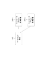
- FIG. 1 is a block diagram illustrating a configuration of a communication system according to a first embodiment. It is a sequence diagram which illustrates the registration operation
- connection lines between the blocks in each drawing include both bidirectional and unidirectional directions.
- the unidirectional arrow schematically shows the main signal (data) flow and does not exclude bidirectionality.
- an input port and an output port exist at each of an input end and an output end of each connection line, although they are not explicitly shown. The same applies to the input / output interface.
- the gateway device 100 includes a selection unit 101 and a transfer unit 102 as illustrated in FIG.
- the selection unit 101 selects one network address translation among a plurality of network address translation apparatuses (for example, the network address translation apparatuses 200-1 and 200-2 in FIG. 1) that redundantly hold global IP addresses assigned to subscriber terminals. Select a device.
- the transfer unit 102 transfers the packet received from the terminal to the selected network address translation device.
- the network address translation device 200 includes a holding unit 201 and a translation unit 202 as illustrated in FIG.
- the holding unit 201 holds the global IP address assigned to the subscriber's terminal redundantly with other network address translation devices.
- the conversion unit 202 transmits a packet from a gateway device (for example, the gateway device 100 in FIG. 1) that transfers a packet received from the terminal to a network address conversion device selected from a plurality of network address conversion devices that redundantly hold global IP addresses. And translates the packet address using the global IP address.
- gateway device In the communication system, gateway device, and network address translation device according to an embodiment, global IP addresses assigned to subscriber terminals are redundantly held in a plurality of network address translation devices.
- a gateway device provided between the plurality of network address translators and the subscriber's terminal transfers the packet received from the terminal to the network address translator selected from the plurality of network address translators. To do. Therefore, according to the communication system, the gateway device, and the network address translation device according to the embodiment, the global IP address fixed to the subscriber without performing synchronization processing between the redundant network address translation devices. Can be paid out.
- Global IP address refers to an IP address assigned to a subscriber for Internet access.
- the global IP address is stored in a public IP pool that a network address translation device (for example, CGNAT) has.
- the private IP address used in the subscriber's home is converted into a global IP address.
- the “public IP pool” is a pool for storing a global IP address group (usually an IP prefix (IP Prefix)) assigned to a subscriber.
- IP Prefix IP prefix
- the “public IP pair” refers to a pair of public IP pools in which the same IP prefix information is stored in two public IP pools.
- a pair of public IP pools (eg, public IP pools # 10 and # 11) between CGNAT (Carrier Grade Network Address Translator) 20-1 and 20-2.
- CGNAT Carrier Grade Network Address Translator
- AGW Access Gateway
- the selection of the public IP pool is performed by the AGW 10 arranged in the preceding stage of the CGNATs 20-1 and 20-2.
- the AGW 10 forwards the subscriber traffic to the public IP pool having a relatively high priority (that is, a high priority) during normal operation. Also good.
- the AGW 10 performs alive monitoring using ping or the like in order to detect the presence or absence of a failure of the CGNAT that accommodates the public IP pool.
- the AGW 10 detects that the response from the CGNAT is NG, the AGW 10 changes the forwarding destination of the subscriber's traffic to a public IP pool having a relatively low priority (ie, low priority). Note that one ping destination may be set for each CGNAT.
- the public IP pools constituting the pair accommodate the same global IP address (IP prefix), and pay out the global IP address to the subscriber.
- the CGNATs 20-1 and 20-2 obtain information from the CTL server (Control Server) 30 for associating the global IP addresses stored in the public IP pool with subscribers on a one-to-one basis. This makes it possible to assign the same global IP address to the designated subscriber before and after switching between the active / standby system (Active / Standby, ACT / SBY) of the public IP pool.
- the public IP pair that stores the global IP address used by the subscriber may be selected by the AGW 10 in accordance with an instruction from the CTL server 30.
- the public IP pool detects that a packet has been transferred from the AGW 10
- the stored global IP address information is The route is advertised to the upper router.
- the destination of the traffic for the global IP address assigned to the subscriber is kept on the side holding the active (ACT) public IP pool.
- public IP pool # 11 becomes the active system (ACT) instead of public IP pool # 10, and holds the public IP pool of the active system (ACT).
- the destination of the traffic from the Internet side for the global IP address assigned to the subscriber can be transferred to the CGNAT 20-2 side.
- CGNAT Carrier Grade Network Address Translator
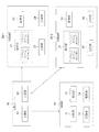
- FIG. 4 illustrates the configuration of the communication system of the present embodiment.
- the communication system includes a broadband access gateway (AGW) 10, two CGNAT (Carrier Grade Network Address Translator) 20-1 and 20-2, and a CTL (Control) server. 30.
- AGW broadband access gateway
- CGNAT Carrier Grade Network Address Translator
- CTL Control server
- a redundant configuration (ACT / SBY configuration) is realized based on a simplified system configuration without performing synchronization processing between the CGNATs 20-1 and 20-2. Further, according to the present embodiment, the network for synchronization signals between CGNATs can be deleted. As a result, the system configuration can be simplified and restrictions on the installation location of CGNAT can be eliminated. Therefore, a CGNAT redundant configuration can be realized by pairing public IP pools between arbitrary CGNATs in the system, and a highly reliable service can be easily realized.
- the configuration and operation of this embodiment will be described in detail.
- the CTL server 30 includes a storage unit 31 and a setting unit 32 as shown in FIG.
- the storage unit 31 holds two tables of public IP pool information (Table 1) and subscriber information (Table 3) described later.
- the setting unit 32 refers to these tables stored in the storage unit 31 and sets information necessary for providing a service to the AGW 10 and the CGNATs 20-1 and 20-2. Setting information by the CTL server 30 will be described in detail in [Operation] described later.
- the AGW 10 includes a selection unit 11, a transfer unit 12, a storage unit 13, and a monitoring unit 14 as shown in FIG.
- the storage unit 13 holds a subscriber identifier, information for identifying a set of public IP pools held by the CGNATs 20-1 and 20-2 (public IP pair information), and subscriber identification information in association with each other.
- the selection unit 11 performs subscriber authentication at the timing when the subscriber first accesses the communication system according to the present embodiment, and acquires public IP pair information that accommodates the subscriber.
- the monitoring unit 14 performs alive monitoring on the public IP pool.
- the monitoring unit 14 performs life and death monitoring using, for example, ping / BFD (Bidirectional Forwarding Detection).
- the monitoring unit 14 performs alive monitoring on the alive monitoring IP address assigned to the CGNATs 20-1 and 20-2.
- the relationship between the IP address for alive monitoring and the public IP pair stored in the CGNATs 20-1 and 20-2 is set by the CTL server 30.
- the monitoring unit 14 confirms that responses from the opposing CGNATs 20-1 and 20-2 are returned.
- the selection unit 11 continues the operation of distributing traffic to the CGNAT.
- the selector 11 distributes the traffic to the latter CGNAT.
- the selection unit 11 sets the high-priority public IP pool as an active system (ACT), and distributes traffic from the subscriber to the CGNAT that holds the public IP pool.
- ACT active system
- the transfer unit 12 encapsulates and transfers the subscriber traffic between the AGW 10 and the CGNATs 20-1 and 20-2.
- the transfer unit 12 adds a subscriber identifier to the header of the packet.
- the transfer unit 12 can use GRE (Generic Routing Encapsulation), which is a general-purpose protocol, in the encapsulation process.
- GRE Generic Routing Encapsulation
- the transfer unit 12 sets a public IP pool address as a destination IP address for the GRE header, and also sets a subscription identifier.
- the route between the AGW 10 and the CGNATs 20-1 and 20-2 can be determined by a general-purpose routing protocol (Routing Protocol).
- the response unit 24 returns a response to the life / death monitoring request from the monitoring unit 14 of the AGW 10.
- alive monitoring may be started at the timing when CGNAT is deployed in the system.
- CGNAT 20-1, 20-2 and AGW 10 are connected by tunnel using GRE (Generic-Routing-Encapsulation) / DS-Lite (Dual-Stack-Lite) etc. for each subscriber, and subscribed by the subscriber identifier in the header Identify the person.
- GRE Generic-Routing-Encapsulation
- DS-Lite Dual-Stack-Lite
- the conversion unit 22 identifies the subscriber based on the subscriber identifier and determines a global IP address to be given to the subscriber.
- the subscriber uses a subscriber specific QinQ (IEEE802.1Q Tunneling) frame (VLAN S-tag (Service tag) / C-tag (Customer-tag)) etc. Can be identified.
- QinQ IEEE802.1Q Tunneling
- the holding unit 21 uniquely associates the global IP address in the public IP pool with the subscriber identifier.
- the association information is set by the CTL server 30 in the CGNATs 20-1 and 20-2.
- the advertising unit 23 advertises the route to the upper router with the global IP address stored in the public IP pool on the ACT side. Thereby, it is possible to control so that traffic from the Internet side is transferred in the direction of the global IP address accommodated in the public IP pool on the ACT side.
- the advertising unit 23 When the advertising unit 23 detects traffic from the AGW 10 toward the Internet, the advertising unit 23 recognizes the public IP pool that accommodates the subscriber of the transmission source of the traffic as an active system (ACT). After recognizing the active system (ACT), the advertising unit 23 advertises the global IP address information assigned to the subscriber to the upper router. When CGNAT ACT / SBY switching occurs, the CGNAT advertising unit 23 having the public IP pool on the side that has newly become the active system (ACT) performs the same processing. Thereby, the upper router switches the route for the CGNAT based on the route advertisement.
- ACT active system
- a service is provided by setting an ACT / SBY public IP pool for CGNATs 20-1 and 20-2 and selecting a public IP pool used by a subscriber by AGW10.
- (1) “setting of management information by the CTL server 30”, (2) “packet transfer sequence”, and (3) “system switching sequence” will be described in order.
- the AGW 10 can determine the packet transfer direction according to the priority. Also, by setting a plurality of public IP pairs in advance for the AGW 10 and setting public IP pairs used by the subscriber, load distribution to the CGNATs 20-1 and 20-2 becomes possible.
- Table 1 illustrates the configuration of a table (“public IP pool information” table) that stores public IP pool information held by the storage unit 31 of the CTL server 30.
- Table 2 shows the contents of parameters managed by the “Public IP Pool Information” table shown in Table 1.
- the CTL server 30 When the subscriber is registered in the system, the CTL server 30 generates a table (“subscriber information” table) that holds the “subscriber information” shown in Table 3 and holds it in the storage unit 31.
- Table 4 shows the contents of parameters managed by the “subscriber information” table shown in Table 3.
- the monitoring unit 14 of the AGW 10 transmits a life / death monitoring packet to the CGNAT IP address instructed from the CTL server 30.
- the timing at which the monitoring unit 14 starts alive monitoring is after the CGNATs 20-1 and 20-2 are incorporated into the communication system.
- the monitoring unit 14 performs a corresponding public IP pool switching operation.
- the AGW 10 can manage the public IP pool information stored in the CGNATs 20-1 and 20-2 by combining the CGNAT IP address information and the public IP pool information. It becomes possible.
- the information of the transfer destination CGNATs 20-1 and 20-2 can be managed by the AGW 10. It becomes possible.
- the CGNATs 20-1 and 20-2 are set. Can manage public IP pool information of its own device.
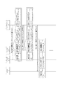
- FIG. 7 is a sequence diagram illustrating an operation in which the setting unit 32 of the CTL server 30 sets the subscriber information in the AGW 10, CGNAT 20-1, and 20-2 when the subscriber is registered in the communication system.
- Table 6 illustrates parameters set by the setting unit 32 of the CTL server 30 in each step of the sequence diagram shown in FIG.
- the conversion unit 22 of the CGNATs 20-1 and 20-2 is transferred from the AGW 10. It is possible to determine which global IP address is assigned to the traffic to be transmitted. In steps B1 and B2 of the sequence diagram of FIG. 7, for example, global IP address 1.1.1.1 is assigned to subscriber #A.
- the subscriber #A is ready to perform communication using the communication system of the present embodiment.
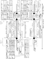
- FIG. 8 is a sequence diagram illustrating an operation in which a subscriber performs packet transfer via the AGW 10 and the CGNAT 20-1.
- the AGW 10 detects traffic from the L2CPE (Layer 2 Customer Premises Equipment) 40 of the subscriber #A
- the selection unit 11 of the AGW 10 refers to the storage unit 13 and assigns the public assigned to the subscriber #A. Determine IP pair # 1.
- the monitoring unit 14 of the AGW 10 monitors the life and death of the CGNATs 20-1 and 20-2 holding the public IP pools # 10 and # 11 included in the public IP pair # 1 corresponding to the subscriber #A.
- the selection unit 11 selects a public IP pool with a high priority based on the alive monitoring result.
- the selection unit 11 selects the CGNAT 20-1 that holds the public IP pool # 10 having a relatively high priority.
- the transfer unit 12 encapsulates the traffic of the subscriber #A using the destination IP address (tunnel IP # 10) and the subscriber identifier (tunnel ID_A), and transfers the encapsulated traffic to the selected CGNAT 20-1.
- the conversion unit 22 of the CGNAT 20-1 determines the corresponding public IP pool (public IP pool # 10) from the destination IP address (tunnel IP # 10) of the header information of the encapsulated packet. Also, the conversion unit 22 determines the subscriber (#A) and the global IP address (1.1.1.1) assigned to the subscriber (#A) from the subscriber identifier (tunnel ID_A) in the header information, and NAPT (Network Address Port Translation) process and transfer to the Internet.
- public IP pool # 10 public IP pool # 10
- the conversion unit 22 determines the subscriber (#A) and the global IP address (1.1.1.1) assigned to the subscriber (#A) from the subscriber identifier (tunnel ID_A) in the header information, and NAPT (Network Address Port Translation) process and transfer to the Internet.
- the transfer unit 12 of the AGW 10 determines the subscriber (#A) using the subscriber identifier (tunnel ID_A) and transfers the packet to the access network side.
- FIG. 9 is a diagram illustrating a tunnel connection between the AGW 10 and the CGNATs 20-1 and 20-2.
- operations of the AGW 10 and the CGNATs 20-1 and 20-2 shown in FIG. 9 will be described.
- the selection unit 11 of the AGW 10 has a subscriber authentication unit for each subscriber.
- the selection unit 11 performs authentication and identification of the subscriber using the subscriber authentication unit, and selects a public IP pair to which the subscriber is connected. Referring to FIG. 9, the selection unit 11 selects the public IP pair # 1 for the subscriber #A. Similarly, the selection unit 11 selects the public IP pair # 2 for the subscriber #X.
- the selection unit 11 selects a public IP pool having a relatively high priority among the public IP pools constituting the pair in the public IP pair. Referring to FIG. 9, the selection unit 11 selects a public IP pool # 10 having a high priority among the public IP pools # 10 and # 11 included in the public IP pair # 1 for the subscriber #A. . Similarly, the selection unit 11 selects the public IP pool # 21 having a high priority among the public IP pools # 20 and # 21 included in the public IP pair # 2 for the subscriber #X.
- the transfer unit 12 of the AGW 10 encapsulates the subscriber traffic for transfer to the IP address assigned to the public IP pool selected by the selection unit 11.
- the destination of the public IP pool is designated from the CTL server 30.
- the transfer unit 12 encapsulates the traffic of the subscriber #A using the IP address (tunnel IP # 10) allocated to the public IP pool # 10, and performs the tunnel header used for encapsulation.
- a subscriber identifier (tunnel ID_A) is assigned and transferred to CGNAT 20-1.
- the transfer unit 12 encapsulates the traffic of the subscriber #X using the IP address (tunnel IP # 21) allocated to the public IP pool # 21, and subscribes the subscriber identifier to the tunnel header used for encapsulation. (Tunnel ID_X) is assigned and transferred to CGNAT 20-2. In this way, by adding a subscriber identifier to the tunnel header used for encapsulation, a tunnel can be generated for each subscriber.
- the CGNATs 20-1 and 20-2 select a public IP pool based on the destination IP address of the tunnel header, and distribute the packet to the public IP pool accommodated in the holding unit 21 of the CGNATs 20-1 and 20-2.
- the CGNAT 20-1 selects the public IP pool (# 10) based on the destination IP address (tunnel IP # 10) of the tunnel header of the packet from the subscriber #A, and holds the CGNAT 20-1 The packet is distributed to the public IP pool # 10 accommodated in the unit 21.
- the monitoring unit 14 of the AGW 10 performs life and death monitoring periodically (for example, periodically) for the registered CGNATs 20-1 and 20-2.
- the selection unit 11 checks the list of public IP pools accommodated in the CGNAT when the response to life and death monitoring is not obtained, and when there is a public IP pool currently used as the ACT, the selection unit 11 The public IP pool of the standby system (SBY) that forms a pair with the new ACT.
- SBY standby system
- the CGNAT conversion unit 22 identifies the subscriber based on the header information of the encapsulated subscriber traffic that has been transferred, determines a global IP address to be assigned to the subscriber, and NAPT (Network Address PortNATranslation). ) Implement the process.
- NAPT Network Address PortNATranslation
- the global IP address assigned to the subscriber the same value is set by the CTL server 30 for both of the public IP pools constituting the pair. Therefore, when the same subscriber identifier is given to the header of the packet by the AGW 10, it is possible to give the same global IP address to the subscriber before and after switching the public IP pool. As a result, traffic in the direction from the AGW 10 to the CGNAT 20-1 or 20-2 can be normally transferred in the Internet direction.
- FIG. 11 illustrates an operation of changing the packet transfer route from the Internet to the CGNAT direction for the CGNAT holding the public IP pool switched to the new ACT.
- the public IP pool that has received the traffic from the subscriber knows that it has been selected as the active system (ACT). Then, the advertising unit 23 advertises a route to the upper router 50 with the global IP address accommodated in the public IP pool.
- the upper router 50 reviews the route information and switches the traffic from the Internet side toward the subscriber via the CGNAT to the direction of the CGNAT holding the public IP pool on the new ACT side.
- the left side of FIG. 11 shows the situation before the failure of CGNAT 20-1.
- the public IP pool # 10 accommodated in the CGNAT 20-1 recognizes itself as an active system (ACT) for the subscriber #A.
- the advertising unit 23 advertises the global IP address (1.1.1.0/24) stored in the public IP pool # 10 to the Internet side via the upper router 50 connected to the CGNAT 20-1.
- the router on the Internet side recognizes that the transfer destination of the packet addressed to the IP address 1.1.1.0/24 is in the direction of CGNAT20-1.
- a synchronization interface can be deleted between CGNATs constituting a pair. Therefore, the same global IP address can be issued to the subscriber before and after the system switching while simplifying the system configuration. Further, according to such a communication system, it is not necessary to transmit / receive synchronization data between CGNATs via the synchronization interface, and it is possible to reduce the bandwidth consumption of the operator network.
- the operator can provide resources (for example, network bandwidth connecting between CGNATs, subscriber accommodation for each CGNAT) to a plurality of CGNATs.
- the pair of public IP pools to be paired can be dynamically set based on the number). That is, the operator can arbitrarily construct a public IP pool pair in CGNAT after introducing the CGNAT facility.
- the public IP pool can be set in consideration of the free resources of CGNAT, and the network design of the ACT / SBY configuration can be arbitrarily performed.
- this effect according to the present embodiment will be described with reference to a comparative example.
- FIG. 12 is a diagram illustrating a redundant (ACT / SBY) configuration of CGNAT according to the comparative example.
- a pair constituting redundancy (a pair of CGNAT 90-1 and 90-2, a pair of CGNAT 90-3 and 90-4) is determined in advance, and synchronization information between the CGNATs It is essential to construct a network for exchanging messages.
- a redundant configuration is realized between CGNAT 90-1 installed at site #A and CGNAT 90-3, 90-4 installed at site #B, between sites #A and #B A spanning synchronization network is required. Therefore, there may be a case in which a redundant configuration cannot be built due to problems such as the distance between the sites #A and #B and the bandwidth.
- FIG. 13 illustrates a redundant configuration of CGNAT when the communication system of this embodiment is applied.
- a pair of public IP pools can be configured by freely combining CGNATs installed between the respective sites.
- Table 8 shows combinations of public IP pools stored in the four CGNATs 20-1 to 20-4 arranged in the four sites #A to #D as shown in FIG.
- FIG. 14 and Table 9 illustrate the ACT / SBY / SBY configuration when the communication system of the present embodiment is used.
- a device for example, AGW 10, CGNAT 20-1, 20-2, CTL server 30 provided in the communication system according to the above embodiment may include an information processing device 60 shown in FIG.
- the information processing apparatus 60 includes a central processing unit (CPU) 61 and a memory 62.
- the information processing apparatus 60 may realize part or all of the functions (see FIG. 5) of the units included in these apparatuses by causing the CPU 61 to execute the program stored in the memory 62.
- the communication system according to the above embodiment can be applied to, for example, BRAS / CGNAT used when a carrier or ISP (Internet Service Provider) provides an Internet access service to a subscriber.
- ISP Internet Service Provider
- the gateway device As in the gateway device according to the first aspect.
- the plurality of network address translation devices have a pool for redundantly holding the global IP address among the plurality of network address translation devices, The selection unit selects a network address translation device having a pool having a relatively high priority from the plurality of network address translation devices;
- the gateway device includes a monitoring unit that monitors the life and death of the plurality of network address translation devices, The selection unit selects a network address translation device having a pool with a relatively low priority when a failure occurs in the network address translation device having a pool with a relatively high priority.
- the gateway device according to mode 2.
- a storage unit that stores association information for identifying a set of pools that redundantly hold the same global IP address and subscriber identification information; 4.
- the gateway device according to mode 2 or 3.
- the selection unit selects one network address translation device from a plurality of network address translation devices having a pool corresponding to the set identification information associated with the subscriber identification information of the subscriber;
- the transfer unit transfers the packet into which the subscriber identification information is inserted to a selected network address translation device. 5.
- the network address conversion device according to the second aspect is as described above.
- the holding unit has a pool for holding the global IP address, Priorities are given to a plurality of pools that the plurality of network address translation devices have to hold the global IP address redundantly, The network address translation device according to mode 6.
- the holding unit stores a global IP address held by the pool in association with subscriber identification information.
- the converting unit converts the address of the packet using a global IP address associated with the subscriber identification information inserted into the packet by the gateway device.
- Mode 10 The communication system according to the third aspect is as described above.
- the plurality of network address translation devices have a pool for redundantly holding the global IP address among the plurality of network address translation devices, The gateway device selects a network address translation device holding a pool having a relatively high priority from the plurality of network address translation devices, and transfers the packet to the selected network address translation device; The communication system according to form 10.
- the gateway device monitors the life and death of the plurality of network address translation devices, and holds a pool with a relatively low priority when a failure occurs in a network address translation device that holds a pool with a relatively high priority. Selecting a network address translator to transfer the packet to the selected network address translator; The communication system according to Form 11.
- the plurality of network address translation devices translate the address of the packet using a global IP address associated with the subscriber identification information inserted into the packet by the gateway device.
- the communication method according to the fourth aspect is as described above.
- the plurality of network address translation devices have a pool for redundantly holding the global IP address among the plurality of network address translation devices,
- the gateway device selects a network address translation device having a pool with a relatively high priority from the plurality of network address translation devices;
- the communication method according to the sixteenth aspect The communication method according to the sixteenth aspect.
- the gateway device includes monitoring a life and death of the plurality of network address translation devices; The gateway device selects a network address translation device having a relatively low priority pool when a failure occurs in the network address translation device having a relatively high priority pool.
- the gateway device includes a step of associating and storing set identification information for identifying a set of pools that redundantly hold the same global IP address and subscriber identification information. The communication method according to Form 17 or 18.
- the gateway device selects one network address translation device from a plurality of network address translation devices having a pool corresponding to the set identification information associated with the subscriber identification information of the subscriber, and the subscriber identification information Forwarding the packet with the inserted to the selected network address translation device, The communication method according to mode 19.
- the communication method according to the fifth aspect is as described above.
- the network address translation device has a pool for storing the global IP address, Priorities are given to a plurality of pools that the plurality of network address translation devices have to hold the global IP address redundantly, The communication method according to Form 21.
Landscapes
- Engineering & Computer Science (AREA)
- Computer Networks & Wireless Communication (AREA)
- Signal Processing (AREA)
- Data Exchanges In Wide-Area Networks (AREA)
Abstract
冗長化されたネットワークアドレス変換装置の間で同期処理を行うことなく、加入者に対して固定したグローバルIPアドレスを払い出すこと。ゲートウェイ装置は、加入者の端末に割り当てるグローバルIPアドレスを冗長に保持する複数のネットワークアドレス変換装置の中から一のネットワークアドレス変換装置を選択する選択部と、選択したネットワークアドレス変換装置に、端末から受信したパケットを転送する転送部と、を備えている。
Description
(関連出願についての記載)
本発明は、日本国特許出願:特願2017-006107号(2017年1月17日出願)の優先権主張に基づくものであり、同出願の全記載内容は引用をもって本書に組み込み記載されているものとする。
本発明は、ゲートウェイ装置、ネットワークアドレス変換装置、通信システム、通信方法、および、プログラムに関し、特に冗長構成を有するネットワークアドレス変換装置と加入者の端末の間に設けられるゲートウェイ装置、CGNAT(Carrier Grade Network Address Translator)等の大規模NAT(LSN:Large Scale NAT)、これらを備えた通信システム、通信方法、および、プログラムに関する。
本発明は、日本国特許出願:特願2017-006107号(2017年1月17日出願)の優先権主張に基づくものであり、同出願の全記載内容は引用をもって本書に組み込み記載されているものとする。
本発明は、ゲートウェイ装置、ネットワークアドレス変換装置、通信システム、通信方法、および、プログラムに関し、特に冗長構成を有するネットワークアドレス変換装置と加入者の端末の間に設けられるゲートウェイ装置、CGNAT(Carrier Grade Network Address Translator)等の大規模NAT(LSN:Large Scale NAT)、これらを備えた通信システム、通信方法、および、プログラムに関する。
加入者につねに同一のグローバルIP(Internet Protocol)アドレスを提供するサービスにおいてCGNAT(Carrier Grade Network Address Translator)を冗長化する場合、一般に2台のCGNATのペアによる冗長構成(ACT/SBY(Active/Standby)構成)が用いられる。ACT/SBYの同期を実現する際、ペアを構成するCGNAT間でNATセッション情報の同期を行うことで、CGNATの切り替えの発生後も加入者に対して同一のグローバルIPアドレスを提供可能となる。
関連技術として、特許文献1には、待機系のNAT(Network Address Translation)装置が運用系のNAT装置に障害などの系の切り替えが必要な事象が生じたか否かを定期的に監視し、系の切り替えが必要と判断したときに自系を運用系に切り替え、他系を待機系に切り替える技術が記載されている。
また、特許文献2には、他のNAPT(Network Address Port Translator)との間で生存確認のためのハートビートデータパケットを定期的に互いに送信し、他のNAPTからのハートビートが途切れたことを検出して、他のNAPTのグローバルアドレスを引き継ぐ技術が記載されている。
さらに、特許文献3には、現用系NAT装置と予備系NAT装置を備え、現用系NAT装置は、アドレス変換前後のパケットを予備系NAT装置に転送し、予備系NAT装置は現用系NAT装置から受け取ったアドレス変換前後のパケットから、アドレス変換を行うための変換情報を生成する技術が記載されている。
上記特許文献の全開示内容は、本書に引用をもって繰り込み記載されているものとする。以下の分析は、本発明者によってなされたものである。
上述の冗長構成に基づく通信システムには、以下の問題が存在する。
(1)CGNATのACT/SBYペア間の同期処理のために、広帯域ネットワークが必要となる。同期用ネットワークでは、ペア間でつねに同期用の情報がやり取りされるため、大規模な加入者を収容するCGNATにおいては、同期用トラフィックが増加しオペレータが管理するネットワークの帯域を圧迫する。また、ACT/SBYを同期させる場合、広帯域を必要とする同期用トラヒックを考慮すると、ACT/SBYのペアを物理的に離れた場所に設置することが困難となる。
(2)ACT/SBY構成のノードに外部装置からアクセスする場合、1つの仮想IPをACT/SBY側ノードで予め設定し、外部装置はこの仮想IPに向けてトラヒックを送信する運用となる。したがって、ネットワーク構成および機器設置の自由度に制約が発生し、設置したCGNAT設備に対して加入者を有効に収容できない可能性がある。
(3)ACT/SBYのペアで運用時、故障が発生すると片系での運用となる。したがって、オペレータは早急に故障箇所の回復作業を行う必要があり、24時間の保守体制を維持する必要がある。
(1)CGNATのACT/SBYペア間の同期処理のために、広帯域ネットワークが必要となる。同期用ネットワークでは、ペア間でつねに同期用の情報がやり取りされるため、大規模な加入者を収容するCGNATにおいては、同期用トラフィックが増加しオペレータが管理するネットワークの帯域を圧迫する。また、ACT/SBYを同期させる場合、広帯域を必要とする同期用トラヒックを考慮すると、ACT/SBYのペアを物理的に離れた場所に設置することが困難となる。
(2)ACT/SBY構成のノードに外部装置からアクセスする場合、1つの仮想IPをACT/SBY側ノードで予め設定し、外部装置はこの仮想IPに向けてトラヒックを送信する運用となる。したがって、ネットワーク構成および機器設置の自由度に制約が発生し、設置したCGNAT設備に対して加入者を有効に収容できない可能性がある。
(3)ACT/SBYのペアで運用時、故障が発生すると片系での運用となる。したがって、オペレータは早急に故障箇所の回復作業を行う必要があり、24時間の保守体制を維持する必要がある。
また、特許文献1、2に記載された技術によると、待機系NATと運用系NATとを切り替える際に、運用系NATが保持するアドレス変換用の情報(例えばNATテーブル)を待機系NATに送出して同期をとる必要があり、同期用トラフィックの一時的な増加により、オペレータが管理するネットワークの帯域を圧迫する可能性がある。
同様に、特許文献3に記載された技術においても、現用系NAT装置から予備系NAT装置に対してアドレス変換前後のパケットを転送する必要があり、オペレータが管理するネットワークの帯域を圧迫する可能性がある。
そこで、冗長化されたネットワークアドレス変換装置の間で同期処理を行うことなく、加入者に対して固定したグローバルIPアドレスを払い出すことが課題となる。本発明の目的は、かかる課題解決に寄与するゲートウェイ装置、ネットワークアドレス変換装置、通信システム、通信方法、および、プログラムを提供することにある。
本発明の第1の態様に係るゲートウェイ装置は、加入者の端末に割り当てるグローバルIPアドレスを冗長に保持する複数のネットワークアドレス変換装置の中から一のネットワークアドレス変換装置を選択する選択部と、選択したネットワークアドレス変換装置に、前記端末から受信したパケットを転送する転送部と、を備えている。
本発明の第2の態様に係るネットワークアドレス変換装置は、加入者の端末に割り当てるグローバルIPアドレスを他のネットワークアドレス変換装置との間で冗長に保持する保持部と、前記グローバルIPアドレスを冗長に保持する複数のネットワークアドレス変換装置の中から選択したネットワークアドレス変換装置に前記端末から受信したパケットを転送するゲートウェイ装置から前記パケットを受信し、前記グローバルIPアドレスを用いて前記パケットのアドレスを変換する変換部と、を備えている。
本発明の第3の態様に係る通信システムは、加入者の端末に割り当てるグローバルIPアドレスを冗長に保持する複数のネットワークアドレス変換装置と、前記複数のネットワークアドレス変換装置の中から選択したネットワークアドレス変換装置に、前記端末から受信したパケットを転送するゲートウェイ装置と、を備えている。
本発明の第4の態様に係る通信方法は、ゲートウェイ装置が、加入者の端末に割り当てるグローバルIPアドレスを冗長に保持する複数のネットワークアドレス変換装置のうちの一のネットワークアドレス変換装置を選択するステップと、選択したネットワークアドレス変換装置に、前記端末から受信したパケットを転送するステップと、を含む。
本発明の第5の態様に係る通信方法は、ネットワークアドレス変換装置が、加入者の端末に割り当てるグローバルIPアドレスを他のネットワークアドレス変換装置との間で冗長に保持するステップと、前記グローバルIPアドレスを冗長に保持する複数のネットワークアドレス変換装置の中から選択したネットワークアドレス変換装置に前記端末から受信したパケットを転送するゲートウェイ装置から、前記パケットを受信するステップと、前記グローバルIPアドレスを用いて前記パケットのアドレスを変換するステップと、を含む。
本発明の第6の態様に係るプログラムは、加入者の端末に割り当てるグローバルIPアドレスを冗長に保持する複数のネットワークアドレス変換装置のうちの一のネットワークアドレス変換装置を選択する処理と、選択したネットワークアドレス変換装置に、前記端末から受信したパケットを転送する処理と、をコンピュータに実行させる。なお、プログラムは、非一時的なコンピュータ可読記録媒体(non-transitory computer-readable storage medium)に記録されたプログラム製品として提供することもできる。
本発明に係るゲートウェイ装置、ネットワークアドレス変換装置、通信システム、通信方法、および、プログラムによると、冗長化されたネットワークアドレス変換装置の間で同期処理を行うことなく、加入者に対して固定したグローバルIPアドレスを払い出すことができる。
はじめに、一実施形態の概要について説明する。なお、この概要に付記する図面参照符号は、専ら理解を助けるための例示であり、本発明を図示の態様に限定することを意図するものではない。また、各図におけるブロック間の接続線は、双方向及び単方向の双方を含む。一方向矢印については、主たる信号(データ)の流れを模式的に示すものであり、双方向性を排除するものではない。さらに、本願開示に示す回路図、ブロック図、内部構成図、接続図などにおいて、明示は省略するが、入力ポート及び出力ポートが各接続線の入力端及び出力端のそれぞれに存在する。入出力インターフェイスも同様である。
一実施形態に係る通信システムは、図1に例示するように、複数のネットワークアドレス変換装置200-1、200-2(例えば図4のCGNAT(Carrier Grade Network Address Translator)20-1、20-2)と、ゲートウェイ装置100(例えば図4のAGW(Access Gateway)10)とを備えている。複数のネットワークアドレス変換装置200-1、200-2は、加入者(例えば図4の加入者#A)の端末に割り当てるグローバルIP(Internet Protocol)アドレスを冗長に保持する。ゲートウェイ装置100は、複数のネットワークアドレス変換装置200-1、200-2の中から選択したネットワークアドレス変換装置に、端末から受信したパケットを転送する。
一実施形態に係るゲートウェイ装置100は、図2に例示するように、選択部101および転送部102を備えている。選択部101は、加入者の端末に割り当てるグローバルIPアドレスを冗長に保持する複数のネットワークアドレス変換装置(例えば図1のネットワークアドレス変換装置200-1、200-2)の中から一のネットワークアドレス変換装置を選択する。転送部102は、選択したネットワークアドレス変換装置に、端末から受信したパケットを転送する。
一実施形態に係るネットワークアドレス変換装置200(例えば図1のネットワークアドレス変換装置200-1、200-2)は、図3に例示するように、保持部201および変換部202を備えている。保持部201は、加入者の端末に割り当てるグローバルIPアドレスを他のネットワークアドレス変換装置との間で冗長に保持する。変換部202は、グローバルIPアドレスを冗長に保持する複数のネットワークアドレス変換装置の中から選択したネットワークアドレス変換装置に端末から受信したパケットを転送するゲートウェイ装置(例えば図1のゲートウェイ装置100)からパケットを受信し、グローバルIPアドレスを用いてパケットのアドレスを変換する。
一実施形態に係る通信システム、ゲートウェイ装置、および、ネットワークアドレス変換装置では、加入者の端末に割り当てるグローバルIPアドレスを複数のネットワークアドレス変換装置に冗長に保持する。また、複数のネットワークアドレス変換装置と加入者の端末との間に設けられたゲートウェイ装置によって、複数のネットワークアドレス変換装置の中から選択したネットワークアドレス変換装置に対して、端末から受信したパケットを転送する。したがって、一実施形態に係る通信システム、ゲートウェイ装置、および、ネットワークアドレス変換装置によると、冗長化されたネットワークアドレス変換装置の間で同期処理を行うことなく、加入者に対して固定したグローバルIPアドレスを払い出すことが可能となる。
ここで、本願開示における用語について説明する。「グローバルIPアドレス」とは、加入者に対して、インターネットアクセス用に割り当てるIPアドレスをいう。また、グローバルIPアドレスは、ネットワークアドレス変換装置(例えばCGNAT)が有するパブリックIPプール内に格納される。加入者の宅内で使用されるプライベートIPアドレスは、グローバルIPアドレスに変換される。また、「パブリックIPプール」とは、加入者に割り当てるグローバルIPアドレス群を(通常は、IPプレフィックス(IP Prefix))格納するためのプールである。さらに、「パブリックIPペア」とは、2個のパブリックIPプール内に、同一のIPプレフィックス情報を格納したパブリックIPプールのペアを指す。
次に、一実施形態の他の構成について説明する。一実施形態の他の構成では、図4に示すように、CGNAT(Carrier Grade Network Address Translator)20-1、20-2の間でパブリックIPプールのペア(例えば、パブリックIPプール#10と#11のペア、パブリックIPプール#20と#21のペアなど)を構成し、ペアの情報をAGW(Access Gateway)10に設定する。これにより、パブリックIPプールの選択をCGNAT20-1、20-2の前段に配置されたAGW10で実施する。AGW10は、ペアを構成するパブリックIPプールに付与された優先度に従って、通常運用時は、優先度が相対的に高い(すなわち高優先の)パブリックIPプールに向けて加入者のトラフィックを転送してもよい。
また、AGW10は、パブリックIPプールを収容したCGNATの障害の有無を検出するために、ping等を用いて死活監視を行うことが好ましい。AGW10は、CGNATからの応答がNGであることを検出すると、加入者のトラフィックの転送先を優先度が相対的に低い(すなわち低優先の)パブリックIPプールに変更する。なお、pingの宛先はCGNAT毎に1個設定してもよい。
ペアを構成するパブリックIPプール(例えば図4のパブリックIPプール#10と#11)は、同一のグローバルIPアドレス(IPプレフィックス)を収容し、その中から加入者にグローバルIPアドレスを払い出す。CGNAT20-1、20-2は、パブリックIPプールに格納されたグローバルIPアドレスを、加入者と1対1で対応させるための情報をCTLサーバ(Control Server)30から取得する。これにより、パブリックIPプールの稼動系/待機系(Active/Standby、ACT/SBY)の切り替え前後において、同一のグローバルIPアドレスを指定された加入者に割り当てることが可能となる。なお、加入者が用いるグローバルIPアドレスを格納するパブリックIPペアはAGW10がCTLサーバ30からの指示に従って選択してもよい。
パブリックIPプール(例えば図4のパブリックIPプール#10、#11、#20、#21)は、AGW10からパケットが転送されて来たことを検出すると、格納しているグローバルIPアドレスの情報を、上位ルータにルート(route)広告する。これにより、稼動系(ACT)のパブリックIPプールを保持するCGNATが切り替わった後も、加入者に割り当てたグローバルIPアドレス向けのトラフィックの宛先を、稼動系(ACT)のパブリックIPプールを保持する側のCGNATに転送することが可能となる。例えば、図4において、CGNAT20-1に障害が発生し、パブリックIPプール#10の代わりにパブリックIPプール#11が新たに稼動系(ACT)となり、稼動系(ACT)のパブリックIPプールを保持するCGNATがCGNAT20-1からCGNAT20-2に切り替わった後、加入者に割り当てたグローバルIPアドレス向けのインターネット側からのトラフィックの宛先を、CGNAT20-2側に転送することが可能となる。
<実施形態1>
次に、第1の実施形態に係る通信システムについて、図面を参照して詳細に説明する。
次に、第1の実施形態に係る通信システムについて、図面を参照して詳細に説明する。
本実施形態では、加入者にプライベートIP(Internet Protocol)アドレスを払い出す固定系ブロードバンド(broadband)サービスにおけるCGNAT(Carrier Grade Network Address Translator)の冗長構成方式について、以下の(1)~(3)の実現を図る。なお、本実施形態では、加入者に対して固定したグローバルIPアドレスを払い出すサービスを想定し、加入者とグローバルIPアドレスは1対1で対応するものとする。
(1)CGNAT間の同期処理を行うことなく、加入者に対して同一グローバルIPアドレスを引き継ぐことが可能な、簡易的なCGNATの冗長構成(ACT/SBY(Active/Standby)構成)を実現する。ただし、加入者のNATのセッションは引き継がれないものとする。
(2)物理的に離れた任意のCGNAT間で冗長ペアを構成し、柔軟なネットワーク構成を可能とする。
(3)固定的に冗長ペアノードを括りつける同期処理によるACT/SBY構成では実現が困難な3台以上のCGNAT冗長構成を容易に実現する。
(2)物理的に離れた任意のCGNAT間で冗長ペアを構成し、柔軟なネットワーク構成を可能とする。
(3)固定的に冗長ペアノードを括りつける同期処理によるACT/SBY構成では実現が困難な3台以上のCGNAT冗長構成を容易に実現する。
図4は、本実施形態の通信システムの構成を例示する。図4を参照すると、通信システムは、ブロードバンドアクセスゲートウェイ(Broadband Access Gateway、AGW)10と、2台のCGNAT(Carrier Grade Network Address Translator)20-1、20-2と、CTL(Control、制御)サーバ30とを備えている。
AGW10は、加入者(具体的には加入者のL2CPE(Layer 2 Customer Premises Equipment)など)からのトラフィックをCGNAT20-1、20-2に転送する。CGNAT20-1、20-2は、加入者にインターネットアクセス用のグローバルIP(Internet Protocol)アドレスを付与する。CTLサーバ30は、AGW10とCGNAT20-1、20-2に対して必要な情報を設定する。
本実施形態では、CTLサーバ30からの設定情報を元に、AGW10と2台のCGNAT20-1、20-2が連携して動作することで、CGNAT20-1、20-2の冗長構成(ACT/SBY(Active/Standby)構成)を実現し、CGNATの切り替え後も加入者に対して同一のグローバルIPアドレスを適用可能とする。なお、CTLサーバ30による設定タイミングについては後述する。
また、本実施形態では、CGNAT20-1、20-2の間で同期処理を行うことなく、簡素化されたシステム構成に基づいて冗長構成(ACT/SBY構成)を実現する。また、本実施形態によると、CGNAT間の同期信号用のネットワークを削除することができる。これにより、システム構成を簡素化し、CGNATの設置場所に関する制約をなくすことも可能となる。したがって、システム内で任意のCGNAT間のパブリックIPプールをペアとしてCGNAT冗長構成を実現でき、高信頼性サービスを容易に実現することが可能となる。以下、本実施形態の構成および動作について詳述する。
[構成]
まず、本実施形態の通信システムに含まれるCTLサーバ30、AGW10、および、CGNAT20-1、20-2の詳細について説明する。図5は、本実施形態の通信システムの構成を例示するブロック図である。
まず、本実施形態の通信システムに含まれるCTLサーバ30、AGW10、および、CGNAT20-1、20-2の詳細について説明する。図5は、本実施形態の通信システムの構成を例示するブロック図である。
CTLサーバ30は、図5に示すように記憶部31および設定部32を備えている。
記憶部31は、後述するパブリックIPプール情報(表1)および加入者情報(表3)の2つのテーブルを保持する。設定部32は、記憶部31が保持するこれらのテーブルを参照して、AGW10およびCGNAT20-1、20-2に対して、サービスを提供するために必要な情報を設定する。CTLサーバ30による設定情報については、後述の[動作]において詳述する。
AGW10は、図5に示すように選択部11、転送部12、記憶部13および監視部14を備えている。
記憶部13は、加入者の識別子とCGNAT20-1、20-2が保持するパブリックIPプールの組を識別する情報(パブリックIPペア情報)と加入者識別情報とを関連付けて保持する。選択部11は、加入者が本実施形態に係る通信システムに最初にアクセスして来たタイミングにおいて加入者認証を行い、当該加入者を収容するパブリックIPペア情報を取得する。
記憶部13は、CGNAT20-1、20-2がグローバルIPアドレスを格納するためにそれぞれ保持するプールの間の優先度(priority)を示す情報を保持する。選択部11は、ペアを構成する2個(または3個以上)のパブリックIPプールに対して、CTLサーバ30により優先度が付与されて設定されていることを認識する。
監視部14は、パブリックIPプールに対して死活監視を実施する。監視部14は、例えばping/BFD(Bidirectional Forwarding Detection)等を用いて死活監視を行う。ここで、監視部14は、CGNAT20-1、20-2に割り当てられた死活監視用のIPアドレスに対して死活監視を行う。なお、死活監視用IPアドレスと、CGNAT20-1、20-2に格納されるパブリックIPペアとの関係は、CTLサーバ30より設定される。監視部14は、対向するCGNAT20-1、20-2からの応答が返信されることを確認する。相対的に高い優先度(高優先)のパブリックIPプールを保持するCGNATから応答がある場合、選択部11は当該CGNATへのトラフィックの振り分け動作を継続する。一方、高優先のパブリックIPプールを保持するCGNATからの応答がなく、かつ、相対的に低い優先度の(例えば、次に高い優先度を有する)パブリックIPプールを保持するCGNATから応答が得られている場合、選択部11は後者のCGNATにトラフィックを振り分ける。なお、両方のパブリックIPプールから応答がある場合、選択部11は高優先のパブリックIPプールを稼働系(ACT)とし、加入者からのトラフィックを、当該パブリックIPプールを保持するCGNATに振り分ける。
転送部12は、AGW10とCGNAT20-1、20-2の間で加入者トラフィックをカプセル化して転送する。ここで、転送部12はカプセル化する際、パケットのヘッダに加入者識別子を付与する。転送部12は、カプセル化処理において、汎用的なプロトコルであるGRE(Generic Routing Encapsulation)等を用いることができる。転送部12は、GREヘッダに対して、宛先IPアドレスとしてパブリックIPプールアドレスを設定し、併せて加入識別子を設定する。また、AGW10とCGNAT20-1、20-2(ないし、これらが保持するパブリックIPプール)間の経路は、汎用のルーティングプロトコル(Routing Protocol)により決定することができる。
CGNAT20-1、20-2は、図5に示すように保持部21、変換部22、および、広告部23を備えている。
応答部24は、AGW10の監視部14からの死活監視要求に対して、応答を返信する。ここで、死活監視は、システムにCGNATを配備したタイミングで開始してもよい。
保持部21は、加入者に割り当てるグローバルIPアドレスを格納するパブリックIPプールを保持し、冗長の管理はパブリックIPプール単位で実施する。同一のグローバルIPアドレスを格納するパブリックIPプールを、2つのCGNAT20-1、20-2に格納することで、CGNATの切り替え後も加入者に対して同一のグローバルIPアドレスを付与することが可能となる。
CGNAT20-1、20-2とAGW10との間は、加入者単位でGRE(Generic Routing Encapsulation)/DS-Lite(Dual-Stack Lite)等を用いてトンネル接続し、ヘッダ内の加入者識別子で加入者を識別する。AGW10は、加入者に対して一意の加入者識別子を付与する。
変換部22は加入者識別子に基づいて加入者を識別し、当該加入者に付与するグローバルIPアドレスを決定する。なお、AGW10においては、アクセス網で付与される加入者固有のQinQ(IEEE802.1Q Tunneling)フレーム(VLANのS-tag(Service tag)/C-tag(Customer-tag))等を用いて加入者識を識別することができる。
保持部21は、加入者識別子に対して、一意にパブリックIPプール内のグローバルIPアドレスを紐付ける。なお、紐付けの情報は、CTLサーバ30よってCGNAT20-1、20-2に設定される。
また、パブリックIPプールの冗長ペアに係る構成管理はAGW10の側で実施し、CGNAT20-1、20-2の側では実施しない。
広告部23は、ACT側のパブリックIPプールに格納したグローバルIPアドレスを、上位ルータに対してルート広告する。これにより、インターネット側からのトラフィックを、ACT側のパブリックIPプールに収容するグローバルIPアドレス方向に転送するように制御できる。
広告部23は、AGW10からインターネット方向へのトラフィックを検出すると、当該トラフィックの送信元の加入者を収容するパブリックIPプールを稼働系(ACT)として認識する。稼働系(ACT)であることを認識した後、広告部23は加入者に割り当てるグローバルIPアドレス情報を上位ルータにルート広告する。CGNATのACT/SBYの切り替えが発生した場合、新たに稼働系(ACT)となった側のパブリックIPプールを有するCGNATの広告部23が同様の処理を実行する。これにより、上位ルータはルート広告に基づきCGNAT向けの経路の切り替えを実施する。
[動作]
次に、本実施形態に係る通信システムの動作について説明する。
次に、本実施形態に係る通信システムの動作について説明する。
以下に詳述するように、CGNAT20-1、20-2に対してACT/SBYのパブリックIPプールを設定し、加入者が用いるパブリックIPプールをAGW10によって選択することで、サービスを提供する。以下では、(1)「CTLサーバ30による管理情報の設定」、(2)「パケット転送シーケンス」、(3)「系切り替えシーケンス」について、順に説明する。
(1)「CTLサーバ30による管理情報の設定」
システムのオペレータは、AGW10およびCGNAT20-1、20-2に対して設定する「パブリックIPプール情報」テーブルと、加入者をシステムに登録する際にAGW10およびCGNAT20-1、20-2に設定するための「加入者情報」テーブルをCTLサーバ30に設定する。
システムのオペレータは、AGW10およびCGNAT20-1、20-2に対して設定する「パブリックIPプール情報」テーブルと、加入者をシステムに登録する際にAGW10およびCGNAT20-1、20-2に設定するための「加入者情報」テーブルをCTLサーバ30に設定する。
CTLサーバ30は、加入者にグローバルIPを付与するパブリックIPプールを管理する。CTLサーバ30は、同一のグローバルIPを格納する2つのパブリックIPプールでペアを構成し、各パブリックIPプールに優先度を付与する。CTLサーバ30は、例えば、2つのパブリックIPプールのそれぞれに対して、優先度100, 200を付与する。ここでは、一例として、優先度の数値が相対的に小さいものを高優先とする。
優先度が付されたパブリックIPプールをAGW10に設定することで、AGW10は優先度に従ってパケットの転送方向を決定することが可能となる。また、AGW10に対して複数のパブリックIPペアを予め設定し、加入者が用いるパブリックIPペアを設定することで、CGNAT20-1、20-2に対する負荷分散が可能となる。
表1は、CTLサーバ30の記憶部31が保持するパブリックIPプール情報を格納したテーブル(「パブリックIPプール情報」テーブル)の構成を例示する。
表1:「パブリックIPプール情報」テーブル

また、表2は表1に示す「パブリックIPプール情報」テーブルで管理するパラメータの内容を表す。
表2:「パブリックIPプール情報」パラメータ

CTLサーバ30は、加入者がシステムに登録される際、表3に示す「加入者情報」を保持するテーブル(「加入者情報」テーブル)を生成して記憶部31に保持する。
表3:「加入者情報」テーブル
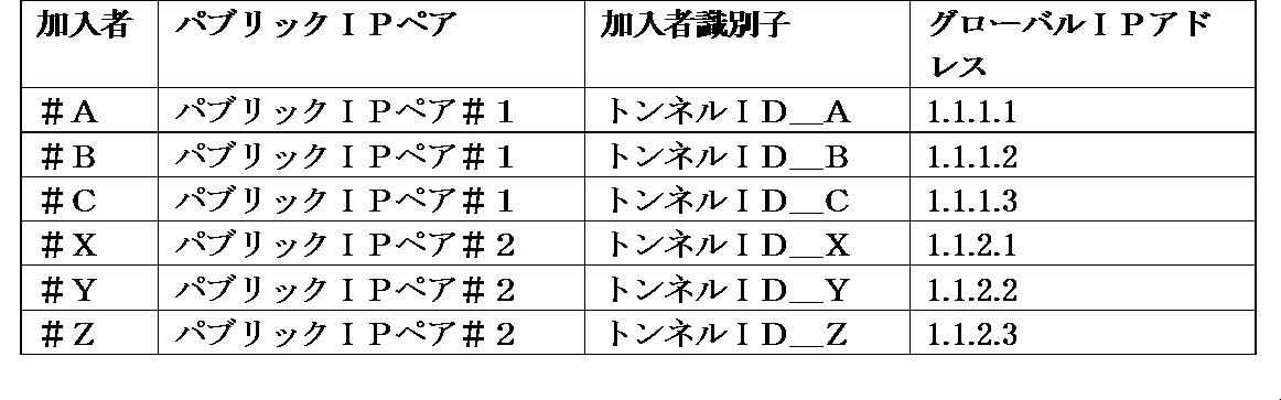
表4は、表3に示す「加入者情報」テーブルで管理するパラメータの内容を表す。
表4:加入者情報パラメータ

表1および表2のテーブルで管理されているパラメータを、以下の図6および図7に示すシーケンスに従ってAGW10、CGNAT20-1、20-2に設定する。これにより、サービスの提供を実施する。
図6は、CTLサーバ30の設定部32が、記憶部31に記録された「パブリックIPプール情報」テーブルに含まれる情報をAGW10およびCGNAT20-1、20-2に登録する動作を例示するシーケンス図である。表5は、図6に示すシーケンス図の各ステップでCTLサーバ30の設定部32が設定するパラメータを示す。
表5:「パブリックIPプール情報」設定シーケンス
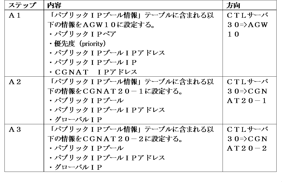
AGW10の監視部14は、CTLサーバ30から指示されたCGNAT IPアドレスに対して、死活監視用のパケットを送信する。ここで、監視部14が死活監視を開始するタイミングは、CGNAT20-1、20-2が通信システムに組み込まれた後とする。監視部14は、死活監視の応答がない場合、対応するパブリックIPプールの切り替え作業を実施する。また、CGNAT IPアドレスはCGNAT毎に設定されるため、CGNAT IPアドレス情報とパブリックIPプール情報を組み合わせることで、CGNAT20-1、20-2に格納されるパブリックIPプール情報をAGW10が管理することが可能となる。
また、優先度を付与したパブリックIPプールのペアと、それぞれのパブリックIPプールの宛先IPアドレスをAGW10に設定することで、転送先のCGNAT20-1、20-2の情報をAGW10で管理することが可能となる。
さらに、CGNAT20-1、20-2に対して、同一のグローバルIPを格納するパブリックIPプールと、そのパブリックIPプールにトラフィックを振り分けるためのIPアドレスを設定することで、CGNAT20-1、20-2は自装置が有するパブリックIPプールの情報を管理することが可能となる。
図7は、加入者が通信システムに登録される際、CTLサーバ30の設定部32が加入者情報をAGW10、CGNAT20-1、20-2に設定する動作を例示するシーケンス図である。また、表6は、図7に示すシーケンス図の各ステップでCTLサーバ30の設定部32が設定するパラメータを例示する。
表6:「加入者情報」設定シーケンス

CGNAT20-1、20-2の保持部21に加入者(加入者識別子)と、その加入者に対するグローバルIPアドレスを設定することで、CGNAT20-1、20-2の変換部22はAGW10から転送されるトラフィックに対して、どのグローバルIPアドレスを割り当てるかを決定することができる。図7のシーケンス図のステップB1、B2では、一例として加入者#Aに対してグローバルIPアドレス1.1.1.1を割り当てる。
AGW10の選択部11は、記憶部13を参照して加入者(加入者識別子)に適用するパブリックIPペアを求めることで、転送先のパブリックIPプールを決定する。図7のシーケンス図のステップB3では、加入者#Aに対して、パブリックIPプール#10、#11から成るパブリックIPペア#1(表1)を割り当てる。このとき、選択部11は、加入者#AのトラフィックをパブリックIPプール#10または#11に転送することを決定する。
図7のシーケンスの完了後、加入者#Aが本実施形態の通信システムを用いて通信を行うための準備が整う。
(2)「パケット転送シーケンス」
図8は、加入者がAGW10およびCGNAT20-1を介してパケット転送を行う動作を例示するシーケンス図である。
図8は、加入者がAGW10およびCGNAT20-1を介してパケット転送を行う動作を例示するシーケンス図である。
まず、AGW10からCGNAT20-1の方向へのパケット転送について説明する。図8を参照すると、AGW10が加入者#AのL2CPE(Layer 2 Customer Premises Equipment)40からのトラフィックを検出すると、AGW10の選択部11は記憶部13を参照して加入者#Aに割り当てたパブリックIPペア#1を確定する。
AGW10の監視部14は、加入者#Aに対応するパブリックIPペア#1に含まれるパブリックIPプール#10、#11を保持するCGNAT20-1、20-2の死活を監視する。選択部11は、死活監視結果に基づいて、優先度の高いパブリックIPプールを選択する。ここでは、パブリックIPペア#1に含まれるパブリックIPプール#10、#11をそれぞれ保持するCGNAT20-1、20-2のいずれについても障害がないものとする。この場合、選択部11は、優先度が相対的に高いパブリックIPプール#10を保持するCGNAT20-1を選択する。転送部12は、宛先IPアドレス(トンネルIP#10)と加入者識別子(トンネルID_A)を用いて、加入者#Aのトラフィックをカプセル化して、選択したCGNAT20-1に転送する。
CGNAT20-1の変換部22は、カプセル化されたパケットのヘッダ情報の宛先IPアドレス(トンネルIP#10)から対応するパブリックIPプール(パブリックIPプール#10)を確定する。また、変換部22は、ヘッダ情報の加入者識別子(トンネルID_A)から加入者(#A)、および、当該加入者(#A)に割り当てたグローバルIPアドレス(1.1.1.1)を確定し、NAPT(Network Address Port Translation)処理を行い、インターネット方向に転送する。
次に、図8を参照して、CGNAT20-1からAGW10の方向へのパケット転送について説明する。CGNAT20-1の変換部22は、インターネット側から受信したパケットの宛先IPアドレスから加入者(#A)を識別する。変換部22は、AGW10の宛先IPアドレスと加入者識別子(トンネルID_A)を用いて、NAPT処理化したパケットをカプセル化した上で、AGW10に転送する。
AGW10の転送部12は、加入者識別子(トンネルID_A)を用いて、加入者(#A)を確定し、アクセス網側へパケットを転送する。
図9は、AGW10とCGNAT20-1、20-2との間のトンネル接続を例示する図である。以下に、図9に示したAGW10およびCGNAT20-1、20-2の動作について説明する。
AGW10の選択部11は、加入者単位で加入者認証部を有する。選択部11は、加入者認証部を用いて加入者の認証および識別を行い、加入者が接続するパブリックIPペアを選択する。図9を参照すると、選択部11は、加入者#Aに対してパブリックIPペア#1を選択する。同様に、選択部11は、加入者#Xに対してパブリックIPペア#2を選択する。
次に、選択部11は、パブリックIPペア内でペアを構成するパブリックIPプールのうちの優先度が相対的に高いパブリックIPプールを選択する。図9を参照すると、選択部11は、加入者#Aに対して、パブリックIPペア#1に含まれるパブリックIPプール#10、#11のうちの優先度が高いパブリックIPプール#10を選択する。同様に、選択部11は、加入者#Xに対して、パブリックIPペア#2に含まれるパブリックIPプール#20、#21のうちの優先度が高いパブリックIPプール#21を選択する。
AGW10の転送部12は、選択部11が選択したパブリックIPプールに割り振られたIPアドレスに対して加入者トラフィックをカプセル化して転送を行う。ここで、パブリックIPプールの宛先は、CTLサーバ30から指定されている。図9を参照すると、転送部12は、加入者#AのトラフィックをパブリックIPプール#10に割り振られたIPアドレス(トンネルIP#10)を用いてカプセル化し、カプセル化に用いるトンネルヘッダに対して加入者識別子(トンネルID_A)を付与してCGNAT20-1へ転送する。同様に、転送部12は、加入者#XのトラフィックをパブリックIPプール#21に割り振られたIPアドレス(トンネルIP#21)を用いてカプセル化し、カプセル化に用いるトンネルヘッダに対して加入者識別子(トンネルID_X)を付与してCGNAT20-2へ転送する。このように、カプセル化に用いるトンネルヘッダに対して、加入者識別子を付与することで、加入者単位でトンネルを生成することが可能となる。
CGNAT20-1、20-2は、トンネルヘッダの宛先IPアドレスを元にパブリックIPプールを選択し、CGNAT20-1、20-2の保持部21に収容したパブリックIPプール宛にパケットを振り分ける。図9を参照すると、CGNAT20-1は、加入者#Aからのパケットのトンネルヘッダの宛先IPアドレス(トンネルIP#10)を元にパブリックIPプール(#10)を選択し、CGNAT20-1の保持部21に収容したパブリックIPプール#10宛にパケットを振り分ける。同様に、CGNAT20-2は、加入者#Xからのパケットのトンネルヘッダの宛先IPアドレス(トンネルIP#21)を元にパブリックIPプール(#21)を選択し、CGNAT20-2の保持部21に収容したパブリックIPプール#21宛にパケットを振り分ける。
パブリックIPプールは、トンネルヘッダに付与された加入者識別子を元に、加入者の識別を行い、加入者単位で変換部22において確保されたNAPT部にパケットを転送する。NAPT部は、加入者に1対1で割り付けられたグローバルIPアドレスを用いてNAPT処理を行う。図9を参照すると、保持部21が収容するパブリックIPプール#10は、加入者#Aからのパケットのトンネルヘッダに付与された加入者識別子(トンネルID_A)を元に、加入者(#A)を識別し、変換部22において加入者#Aのために確保したNAPT部へパケットを転送する。NAPT部は、加入者#Aに1対1で割り付けられたグローバルIPアドレス(1.1.1.1)を用いてNAPT処理を行う。同様に、保持部21が収容するパブリックIPプール#21は、加入者#Xからのパケットのトンネルヘッダに付与された加入者識別子(トンネルID_X)を元に、加入者(#X)を識別し、変換部22において加入者#Xのために確保したNAPT部へパケットを転送する。NAPT部は、加入者#Xに1対1で割り付けられたグローバルIPアドレス(1.1.2.1)を用いてNAPT処理を行う。
(3)「系切り替えシーケンス」
次に、稼動系(ACT)の(優先度が相対的に高い)パブリックIPプールを保持するCGNATに障害が発生した場合に、待機系(SBY)の(優先度が相対的に低い)パブリックIPプールを保持するCGNATに切り替える動作について説明する。
次に、稼動系(ACT)の(優先度が相対的に高い)パブリックIPプールを保持するCGNATに障害が発生した場合に、待機系(SBY)の(優先度が相対的に低い)パブリックIPプールを保持するCGNATに切り替える動作について説明する。
図10は、加入者#Aに対するパブリックIPペア#1に含まれるACTのパブリックIPプール#10を保持するCGNAT20-1に障害が発生した場合における、SBYのパブリックIPプール#11を保持するCGNAT20-2への切り替え動作を例示するシーケンス図である。表7は、図10のシーケンス図における各ステップC1~C6の内容を示す。
表7:加入者情報設定シーケンス
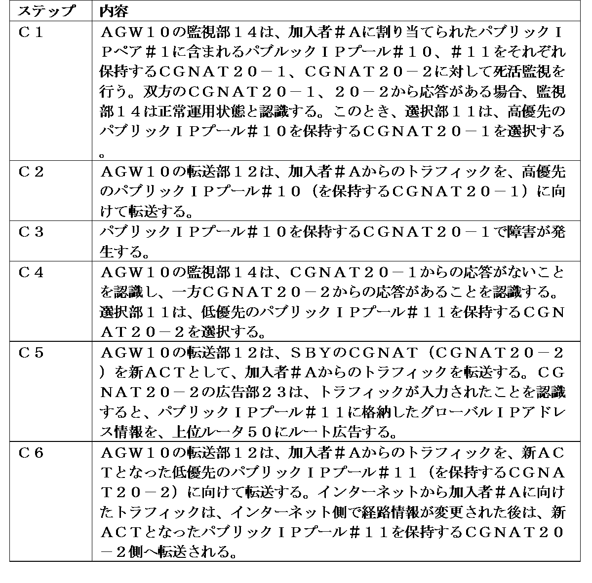
このように、AGW10の監視部14は、登録されたCGNAT20-1、20-2に対して、定期的(例えば周期的)に死活監視を行う。選択部11は、死活監視の応答が得られない場合、当該CGNATに収容されているパブリックIPプールのリストを確認し、現在ACTとして使用しているパブリックIPプールが存在するときには、当該パブリックIPプールとペアを構成する待機系(SBY)のパブリックIPプールを新ACTとする。
これにより、AGW10の転送部12は、新ACTのパブリックIPプールに対して、加入者からのトラフィックを転送することが可能となる。
また、CGNATの変換部22は、転送されてきたカプセル化された加入者トラフィックのヘッダ情報を元に加入者を識別し、当該加入者に割り当てるグローバルIPアドレスを決定してNAPT(Network Address Port Translation)処理を実施する。ここで、加入者に割り当てるグローバルIPアドレスは、CTLサーバ30より、ペアを構成するパブリックIPプールの双方に対して同一の値が設定されている。したがって、AGW10によって同一の加入者識別子がパケットのヘッダに付与された場合、パブリックIPプールの切り替え前後において加入者に同一のグローバルIPアドレスを付与することが可能となる。これにより、AGW10からCGNAT20-1または20-2の方向のトラフィックを、正常にインターネット方向へ転送することが可能となる。
一方、インターネットからCGNAT20-1、20-2方向のトラフィックについては、ネットワークに設置されたルータ50は、新たにACTとしたパブリックIPプールを保持する(稼動中の)CGNATに対してトラフィックを転送する必要がある。このため、ACT側のパブリックIPプールを保持するCGNATの切り替えに伴って、トラフィックの転送方向を変更する必要がある。図11は、新ACTに切り替わったパブリックIPプールを保持するCGNATに対して、インターネットからCGNAT方向へのパケット転送ルートを変更する動作を例示する。
加入者からのトラフィックを受信したパブリックIPプールは、自身が稼動系(ACT)として選択されたことを把握する。すると、広告部23は、当該パブリックIPプールに収容するグローバルIPアドレスを、上位ルータ50にルート広告する。上位ルータ50は、経路情報の見直しを行い、インターネット側からCGNATを経由して加入者方向に向かうトラフィックを、新ACT側のパブリックIPプールを保持するCGNATの方向に切り替える。
図11の左側は、CGNAT20-1に障害が発生する前の状況を示す。CGNAT20-1に収容されているパブリックIPプール#10は、加入者#Aに関して自身を稼動系(ACT)と認識する。このとき、広告部23はパブリックIPプール#10に格納されているグローバルIPアドレス(1.1.1.0/24)を、CGNAT20-1に接続されている上位ルータ50経由でインターネット側にルート広告する。インターネット側のルータはルーティング(routing)テーブルを設定することで、IPアドレス1.1.1.0/24宛てのパケットの転送先は、CGNAT20-1方向であることを認識する。
一方、図11の右側はCGNAT20-1に障害が発生した後の状況を示す。加入者#Aに対する稼動系(ACT)のパブリックIPプールを保持するCGNATの切り替えが生じると、CGNAT20-2に収容されているパブリックIPプール#11は、加入者#Aに関して自身を稼動系(ACT)と認識する。このとき、広告部23はパブリックIPプール#11に格納されているグローバルIPアドレス(1.1.1.0/24)を、CGNAT20-2に接続されている上位ルータ50経由でインターネット側にルート広告する。新たなルート広告を受けたインターネット側のルータは、それぞれルーティングテーブルを更新することで、IPアドレス1.1.1.0/24宛てのパケットの転送先は、CGNAT20-2方向であることを認識する。
[効果]
次に、本実施形態に係る通信システムによってもたらされる効果について説明する。
次に、本実施形態に係る通信システムによってもたらされる効果について説明する。
(1)冗長構成の簡素化
本実施形態の通信システムによると、ペアを構成するCGNAT間で同期用のインタフェースを削除することができる。したがって、システム構成を簡素化しつつ、かつ、加入者に対して系の切り替え前後において同一のグローバルIPアドレスを払い出すことが可能となる。また、かかる通信システムによると、同期用インタフェースを介してCGNAT間で同期データを送受信する必要がなくなり、オペレータネットワークの帯域の消費量を削減することも可能となる。
本実施形態の通信システムによると、ペアを構成するCGNAT間で同期用のインタフェースを削除することができる。したがって、システム構成を簡素化しつつ、かつ、加入者に対して系の切り替え前後において同一のグローバルIPアドレスを払い出すことが可能となる。また、かかる通信システムによると、同期用インタフェースを介してCGNAT間で同期データを送受信する必要がなくなり、オペレータネットワークの帯域の消費量を削減することも可能となる。
(2)プール(pool)構成の自由度向上
また、本実施形態の通信システムによると、オペレータは複数のCGNATに対して、リソース(例えばCGNAT間を接続するネットワークの帯域、CGNATごとの加入者収容数など)に基づいて、ペアとなるパブリックIPプールのペアを動的に設定することができる。すなわち、オペレータはCGNAT設備を導入後に、CGNAT内にパブリックIPプールのペアを任意に構築することが可能となる。
また、本実施形態の通信システムによると、オペレータは複数のCGNATに対して、リソース(例えばCGNAT間を接続するネットワークの帯域、CGNATごとの加入者収容数など)に基づいて、ペアとなるパブリックIPプールのペアを動的に設定することができる。すなわち、オペレータはCGNAT設備を導入後に、CGNAT内にパブリックIPプールのペアを任意に構築することが可能となる。
さらに、本実施形態の通信システムによると、パブリックIPプールのペアを構成する際、地理的条件や同期ネットワーク設定を考慮する必要がない。したがって、CGNATの空きリソースを考慮しつつ、パブリックIPプールの設定を行うことができ、ACT/SBY構成のネットワーク設計を任意に行うことが可能となる。以下、比較例を参照しつつ、本実施形態によるかかる効果について説明する。
図12は、比較例に係るCGNATの冗長(ACT/SBY)構成を例示する図である。比較例によると、図12に示すように、冗長を構成するペア(CGNAT90-1および90-2のペア、CGNAT90-3および90-4のペア)を予め決定し、かつ、CGNAT間で同期情報をやり取りするためのネットワークの構築が必須となる。また、サイト(site)#Aに設置されたCGNAT90-1と、サイト#Bに設置されたCGNAT90-3、90-4との間で冗長構成を実現する場合、サイト#A、#B間をまたがる同期ネットワークが必要とされる。したがって、サイト#A、#B間の距離や帯域等の問題により、冗長構成を組めないようなケースも起こり得る。
一方、図13は、本実施形態の通信システムを応用した場合のCGNATの冗長構成を例示する。このとき、図13に示すように、各サイト間に設置されたCGNATを自由に組み合わせて、パブリックIPプールのペアを構成することができる。また、ペアを構成する際、CGNAT間の同期用ネットワークの設置が不要であるため、ペアの組み合わせには制約が存在しない。したがって、CGNATのリソース状態に応じて、任意のタイミングでペア構成を再構築することも可能となる。表8は、図13に示すように4箇所のサイト#A~#Dに配置した4台のCGNAT20-1~20-4に格納したパブリックIPプールの組み合わせを示す。
表8:ACT/SBY構成例

(3)ACT/SBY/SBY構成の実現
本実施形態の通信システムによると、AGW10側に優先度を付与したパブリックIPプールの情報を3台分設定し、本実施形態で述べた技術を適用することで、3台以上のCGNATから成る冗長機能(例えばACT/SBY/SBY)を、容易に実現することができる。
本実施形態の通信システムによると、AGW10側に優先度を付与したパブリックIPプールの情報を3台分設定し、本実施形態で述べた技術を適用することで、3台以上のCGNATから成る冗長機能(例えばACT/SBY/SBY)を、容易に実現することができる。
ACT/SBY/SBY構成によると、待機系(SBY)が2系統設置されるため、CGNATのうちの1台に障害が発生した場合であっても、ACT/SBY運用を維持することができる。したがって、障害発生時の駆けつけ保守が不要となる。これにより、営業時間内での障害発生装置(例えばCGNAT)の置き換えが可能となり、保守運用の費用を削減することができる。図14および表9は、本実施形態の通信システムを用いた場合のACT/SBY/SBY構成を例示する。
表9:ACT/SBY/SBY構成例

図14および表9に示す構成によると、加入者#AをパブリックIPペア#1に収容して運用する場合、通常運用時はトンネルIP#10を用いる。「トンネルIP#10」に異常(例えばCGNAT20-1に障害)が発生すると、CGNAT20-3に収容した「トンネルIP#12」を新たな稼動系(ACT)に切り替えてサービスを継続する。このとき、CGNAT20-2に収容した「トンネルIP#11」を待機系(SBY)として運用することができる。したがって、保守者による駆けつけ対応が不要となる。
<変形例>
上記実施形態に係る通信システムに設けられた装置(例えばAGW10、CGNAT20-1、20-2、CTLサーバ30)は、図15に示す情報処理装置60を備えていてもよい。情報処理装置60は、中央処理装置(CPU:Central Processing Unit)61およびメモリ62を有する。情報処理装置60は、メモリ62に記憶されているプログラムをCPU61が実行することにより、これらの装置が有する各部の機能(図5参照)の一部または全部を実現してもよい。
上記実施形態に係る通信システムに設けられた装置(例えばAGW10、CGNAT20-1、20-2、CTLサーバ30)は、図15に示す情報処理装置60を備えていてもよい。情報処理装置60は、中央処理装置(CPU:Central Processing Unit)61およびメモリ62を有する。情報処理装置60は、メモリ62に記憶されているプログラムをCPU61が実行することにより、これらの装置が有する各部の機能(図5参照)の一部または全部を実現してもよい。
<応用例>
上記実施形態に係る通信システムは、例えばキャリアまたはISP(Internet Service Provider)が加入者にインターネットアクセスサービスを提供する際に用いるBRAS/CGNATに対して適用することができる。
上記実施形態に係る通信システムは、例えばキャリアまたはISP(Internet Service Provider)が加入者にインターネットアクセスサービスを提供する際に用いるBRAS/CGNATに対して適用することができる。
なお、本願開示おいて、下記の形態が可能である。
[形態1]
上記第1の態様に係るゲートウェイ装置のとおりである。
[形態2]
前記複数のネットワークアドレス変換装置は、前記グローバルIPアドレスを前記複数のネットワークアドレス変換装置の間で冗長に保持するためのプールを有し、
前記選択部は、優先度が相対的に高いプールを有するネットワークアドレス変換装置を前記複数のネットワークアドレス変換装置の中から選択する、
形態1に記載のゲートウェイ装置。
[形態3]
前記ゲートウェイ装置は、前記複数のネットワークアドレス変換装置の死活を監視する監視部を備え、
前記選択部は、優先度が相対的に高いプールを有するネットワークアドレス変換装置に障害が発生した場合、優先度が相対的に低いプールを有するネットワークアドレス変換装置を選択する、
形態2に記載のゲートウェイ装置。
[形態4]
同一のグローバルIPアドレスを冗長に保持するプールの組を識別する組識別情報と加入者識別情報とを関連付けて記憶する記憶部を備える、
形態2または3に記載のゲートウェイ装置。
[形態5]
前記選択部は、前記加入者の加入者識別情報に関連付けられた組識別情報に対応するプールを有する複数のネットワークアドレス変換装置の中から一のネットワークアドレス変換装置を選択し、
前記転送部は、前記加入者識別情報を挿入した前記パケットを、選択したネットワークアドレス変換装置に転送する、
形態4に記載のゲートウェイ装置。
[形態6]
上記第2の態様に係るネットワークアドレス変換装置のとおりである。
[形態7]
前記保持部は、前記グローバルIPアドレスを保持するプールを有し、
前記複数のネットワークアドレス変換装置が前記グローバルIPアドレスを冗長に保持するために有する複数のプールには優先度が付与される、
形態6に記載のネットワークアドレス変換装置。
[形態8]
前記保持部は、前記プールによって保持されるグローバルIPアドレスと加入者識別情報とを関連付けて記憶する、
形態7に記載のネットワークアドレス変換装置。
[形態9]
前記変換部は、前記ゲートウェイ装置が前記パケットに挿入した加入者識別情報に関連付けられたグローバルIPアドレスを用いて、前記パケットのアドレスを変換する、
形態8に記載のネットワークアドレス変換装置。
[形態10]
上記第3の態様に係る通信システムのとおりである。
[形態11]
前記複数のネットワークアドレス変換装置は、前記グローバルIPアドレスを前記複数のネットワークアドレス変換装置の間で冗長に保持するためのプールを有し、
前記ゲートウェイ装置は、優先度が相対的に高いプールを保持するネットワークアドレス変換装置を前記複数のネットワークアドレス変換装置の中から選択し、選択したネットワークアドレス変換装置に前記パケットを転送する、
形態10に記載の通信システム。
[形態12]
前記ゲートウェイ装置は、前記複数のネットワークアドレス変換装置の死活を監視し、優先度が相対的に高いプールを保持するネットワークアドレス変換装置に障害が発生した場合、優先度が相対的に低いプールを保持するネットワークアドレス変換装置を選択し、選択したネットワークアドレス変換装置に前記パケットを転送する、
形態11に記載の通信システム。
[形態13]
前記複数のネットワークアドレス変換装置は、前記プールによって保持されるグローバルIPアドレスと加入者識別情報とを関連付けて記憶し、
前記ゲートウェイ装置は、同一のグローバルIPアドレスを冗長に保持するプールの組を識別する組識別情報と加入者識別情報とを関連付けて記憶する、
形態11または12に記載の通信システム。
[形態14]
前記ゲートウェイ装置は、前記パケットに前記加入者の加入者識別情報を挿入し、前記加入者の加入者識別情報に関連付けられた組識別情報に対応するプールを有する複数のネットワークアドレス変換装置の中から一のネットワークアドレス変換装置を選択し、前記加入者識別情報を挿入した前記パケットを、選択したネットワークアドレス変換装置に転送する、
形態13に記載の通信システム。
[形態15]
前記複数のネットワークアドレス変換装置は、前記ゲートウェイ装置が前記パケットに挿入した加入者識別情報と関連付けられたグローバルIPアドレスを用いて、前記パケットのアドレスを変換する、
形態14に記載の通信システム。
[形態16]
上記第4の態様に係る通信方法のとおりである。
[形態17]
前記複数のネットワークアドレス変換装置は、前記グローバルIPアドレスを前記複数のネットワークアドレス変換装置の間で冗長に保持するためのプールを有し、
前記ゲートウェイ装置は、優先度が相対的に高いプールを有するネットワークアドレス変換装置を前記複数のネットワークアドレス変換装置の中から選択する、
形態16に記載の通信方法。
[形態18]
前記ゲートウェイ装置が、前記複数のネットワークアドレス変換装置の死活を監視するステップを含み、
前記ゲートウェイ装置は、優先度が相対的に高いプールを有するネットワークアドレス変換装置に障害が発生した場合、優先度が相対的に低いプールを有するネットワークアドレス変換装置を選択する、
形態17に記載の通信方法。
[形態19]
前記ゲートウェイ装置が、同一のグローバルIPアドレスを冗長に保持するプールの組を識別する組識別情報と加入者識別情報とを関連付けて記憶するステップを含む、
形態17または18に記載の通信方法。
[形態20]
前記ゲートウェイ装置が、前記加入者の加入者識別情報に関連付けられた組識別情報に対応するプールを有する複数のネットワークアドレス変換装置の中から一のネットワークアドレス変換装置を選択し、前記加入者識別情報を挿入した前記パケットを、選択したネットワークアドレス変換装置に転送する、
形態19に記載の通信方法。
[形態21]
上記第5の態様に係る通信方法のとおりである。
[形態22]
前記ネットワークアドレス変換装置は、前記グローバルIPアドレスを格納するプールを有し、
前記複数のネットワークアドレス変換装置が前記グローバルIPアドレスを冗長に保持するために有する複数のプールには優先度が付与される、
形態21に記載の通信方法。
[形態23]
前記ネットワークアドレス変換装置が、前記プールによって保持されるグローバルIPアドレスと加入者識別情報とを関連付けて記憶するステップを含む、
形態22に記載の通信方法。
[形態24]
前記ネットワークアドレス変換装置は、前記ゲートウェイ装置によって前記パケットに挿入された加入者識別情報に関連付けられたグローバルIPアドレスを用いて、前記パケットのアドレスを変換する、
形態23に記載の通信方法。
[形態25]
ネットワークアドレス変換装置が、加入者の端末に割り当てるグローバルIPアドレスを冗長に保持するステップと、
ゲートウェイ装置が、前記複数のネットワークアドレス変換装置の中から選択したネットワークアドレス変換装置に、前記端末から受信したパケットを転送するステップと、を含む、
ことを特徴とする通信方法。
[形態26]
上記第6の態様に係るプログラムのとおりである。
[形態27]
加入者の端末に割り当てるグローバルIPアドレスを他のネットワークアドレス変換装置との間で冗長に保持する処理と、
前記グローバルIPアドレスを冗長に保持する複数のネットワークアドレス変換装置の中から選択したネットワークアドレス変換装置に前記端末から受信したパケットを転送するゲートウェイ装置から、前記パケットを受信するステップと、
前記グローバルIPアドレスを用いて前記パケットのアドレスを変換するステップと、をネットワークアドレス変換装置に設けられたコンピュータに実行させる、
ことを特徴とするプログラム。
[形態1]
上記第1の態様に係るゲートウェイ装置のとおりである。
[形態2]
前記複数のネットワークアドレス変換装置は、前記グローバルIPアドレスを前記複数のネットワークアドレス変換装置の間で冗長に保持するためのプールを有し、
前記選択部は、優先度が相対的に高いプールを有するネットワークアドレス変換装置を前記複数のネットワークアドレス変換装置の中から選択する、
形態1に記載のゲートウェイ装置。
[形態3]
前記ゲートウェイ装置は、前記複数のネットワークアドレス変換装置の死活を監視する監視部を備え、
前記選択部は、優先度が相対的に高いプールを有するネットワークアドレス変換装置に障害が発生した場合、優先度が相対的に低いプールを有するネットワークアドレス変換装置を選択する、
形態2に記載のゲートウェイ装置。
[形態4]
同一のグローバルIPアドレスを冗長に保持するプールの組を識別する組識別情報と加入者識別情報とを関連付けて記憶する記憶部を備える、
形態2または3に記載のゲートウェイ装置。
[形態5]
前記選択部は、前記加入者の加入者識別情報に関連付けられた組識別情報に対応するプールを有する複数のネットワークアドレス変換装置の中から一のネットワークアドレス変換装置を選択し、
前記転送部は、前記加入者識別情報を挿入した前記パケットを、選択したネットワークアドレス変換装置に転送する、
形態4に記載のゲートウェイ装置。
[形態6]
上記第2の態様に係るネットワークアドレス変換装置のとおりである。
[形態7]
前記保持部は、前記グローバルIPアドレスを保持するプールを有し、
前記複数のネットワークアドレス変換装置が前記グローバルIPアドレスを冗長に保持するために有する複数のプールには優先度が付与される、
形態6に記載のネットワークアドレス変換装置。
[形態8]
前記保持部は、前記プールによって保持されるグローバルIPアドレスと加入者識別情報とを関連付けて記憶する、
形態7に記載のネットワークアドレス変換装置。
[形態9]
前記変換部は、前記ゲートウェイ装置が前記パケットに挿入した加入者識別情報に関連付けられたグローバルIPアドレスを用いて、前記パケットのアドレスを変換する、
形態8に記載のネットワークアドレス変換装置。
[形態10]
上記第3の態様に係る通信システムのとおりである。
[形態11]
前記複数のネットワークアドレス変換装置は、前記グローバルIPアドレスを前記複数のネットワークアドレス変換装置の間で冗長に保持するためのプールを有し、
前記ゲートウェイ装置は、優先度が相対的に高いプールを保持するネットワークアドレス変換装置を前記複数のネットワークアドレス変換装置の中から選択し、選択したネットワークアドレス変換装置に前記パケットを転送する、
形態10に記載の通信システム。
[形態12]
前記ゲートウェイ装置は、前記複数のネットワークアドレス変換装置の死活を監視し、優先度が相対的に高いプールを保持するネットワークアドレス変換装置に障害が発生した場合、優先度が相対的に低いプールを保持するネットワークアドレス変換装置を選択し、選択したネットワークアドレス変換装置に前記パケットを転送する、
形態11に記載の通信システム。
[形態13]
前記複数のネットワークアドレス変換装置は、前記プールによって保持されるグローバルIPアドレスと加入者識別情報とを関連付けて記憶し、
前記ゲートウェイ装置は、同一のグローバルIPアドレスを冗長に保持するプールの組を識別する組識別情報と加入者識別情報とを関連付けて記憶する、
形態11または12に記載の通信システム。
[形態14]
前記ゲートウェイ装置は、前記パケットに前記加入者の加入者識別情報を挿入し、前記加入者の加入者識別情報に関連付けられた組識別情報に対応するプールを有する複数のネットワークアドレス変換装置の中から一のネットワークアドレス変換装置を選択し、前記加入者識別情報を挿入した前記パケットを、選択したネットワークアドレス変換装置に転送する、
形態13に記載の通信システム。
[形態15]
前記複数のネットワークアドレス変換装置は、前記ゲートウェイ装置が前記パケットに挿入した加入者識別情報と関連付けられたグローバルIPアドレスを用いて、前記パケットのアドレスを変換する、
形態14に記載の通信システム。
[形態16]
上記第4の態様に係る通信方法のとおりである。
[形態17]
前記複数のネットワークアドレス変換装置は、前記グローバルIPアドレスを前記複数のネットワークアドレス変換装置の間で冗長に保持するためのプールを有し、
前記ゲートウェイ装置は、優先度が相対的に高いプールを有するネットワークアドレス変換装置を前記複数のネットワークアドレス変換装置の中から選択する、
形態16に記載の通信方法。
[形態18]
前記ゲートウェイ装置が、前記複数のネットワークアドレス変換装置の死活を監視するステップを含み、
前記ゲートウェイ装置は、優先度が相対的に高いプールを有するネットワークアドレス変換装置に障害が発生した場合、優先度が相対的に低いプールを有するネットワークアドレス変換装置を選択する、
形態17に記載の通信方法。
[形態19]
前記ゲートウェイ装置が、同一のグローバルIPアドレスを冗長に保持するプールの組を識別する組識別情報と加入者識別情報とを関連付けて記憶するステップを含む、
形態17または18に記載の通信方法。
[形態20]
前記ゲートウェイ装置が、前記加入者の加入者識別情報に関連付けられた組識別情報に対応するプールを有する複数のネットワークアドレス変換装置の中から一のネットワークアドレス変換装置を選択し、前記加入者識別情報を挿入した前記パケットを、選択したネットワークアドレス変換装置に転送する、
形態19に記載の通信方法。
[形態21]
上記第5の態様に係る通信方法のとおりである。
[形態22]
前記ネットワークアドレス変換装置は、前記グローバルIPアドレスを格納するプールを有し、
前記複数のネットワークアドレス変換装置が前記グローバルIPアドレスを冗長に保持するために有する複数のプールには優先度が付与される、
形態21に記載の通信方法。
[形態23]
前記ネットワークアドレス変換装置が、前記プールによって保持されるグローバルIPアドレスと加入者識別情報とを関連付けて記憶するステップを含む、
形態22に記載の通信方法。
[形態24]
前記ネットワークアドレス変換装置は、前記ゲートウェイ装置によって前記パケットに挿入された加入者識別情報に関連付けられたグローバルIPアドレスを用いて、前記パケットのアドレスを変換する、
形態23に記載の通信方法。
[形態25]
ネットワークアドレス変換装置が、加入者の端末に割り当てるグローバルIPアドレスを冗長に保持するステップと、
ゲートウェイ装置が、前記複数のネットワークアドレス変換装置の中から選択したネットワークアドレス変換装置に、前記端末から受信したパケットを転送するステップと、を含む、
ことを特徴とする通信方法。
[形態26]
上記第6の態様に係るプログラムのとおりである。
[形態27]
加入者の端末に割り当てるグローバルIPアドレスを他のネットワークアドレス変換装置との間で冗長に保持する処理と、
前記グローバルIPアドレスを冗長に保持する複数のネットワークアドレス変換装置の中から選択したネットワークアドレス変換装置に前記端末から受信したパケットを転送するゲートウェイ装置から、前記パケットを受信するステップと、
前記グローバルIPアドレスを用いて前記パケットのアドレスを変換するステップと、をネットワークアドレス変換装置に設けられたコンピュータに実行させる、
ことを特徴とするプログラム。
なお、上記特許文献の全開示内容は、本書に引用をもって繰り込み記載されているものとする。本発明の全開示(請求の範囲を含む)の枠内において、さらにその基本的技術思想に基づいて、実施形態の変更・調整が可能である。また、本発明の全開示の枠内において種々の開示要素(各請求項の各要素、各実施形態の各要素、各図面の各要素等を含む)の多様な組み合わせ、ないし、選択が可能である。すなわち、本発明は、請求の範囲を含む全開示、技術的思想にしたがって当業者であればなし得るであろう各種変形、修正を含むことは勿論である。特に、本書に記載した数値範囲については、当該範囲内に含まれる任意の数値ないし小範囲が、別段の記載のない場合でも具体的に記載されているものと解釈されるべきである。
10 AGW
11 選択部
12 転送部
13 記憶部
14 監視部
20-1~20-4 CGNAT
21 保持部
22 変換部
23 広告部
24 応答部
30 CTLサーバ
31 記憶部
32 設定部
40 L2CPE
50 ルータ
60 情報処理装置
61 中央処理装置(CPU)
62 メモリ
90-1~90-4 CGNAT
100 ゲートウェイ装置
101 選択部
102 転送部
200、200-1、200-2 ネットワークアドレス変換装置
201 保持部
202 変換部
11 選択部
12 転送部
13 記憶部
14 監視部
20-1~20-4 CGNAT
21 保持部
22 変換部
23 広告部
24 応答部
30 CTLサーバ
31 記憶部
32 設定部
40 L2CPE
50 ルータ
60 情報処理装置
61 中央処理装置(CPU)
62 メモリ
90-1~90-4 CGNAT
100 ゲートウェイ装置
101 選択部
102 転送部
200、200-1、200-2 ネットワークアドレス変換装置
201 保持部
202 変換部
Claims (10)
- 加入者の端末に割り当てるグローバルIP(Internet Protocol)アドレスを冗長に保持する複数のネットワークアドレス変換装置の中から一のネットワークアドレス変換装置を選択する選択部と、
選択したネットワークアドレス変換装置に、前記端末から受信したパケットを転送する転送部と、を備える、ゲートウェイ装置。 - 前記複数のネットワークアドレス変換装置は、前記グローバルIPアドレスを前記複数のネットワークアドレス変換装置の間で冗長に保持するためのプールを有し、
前記選択部は、優先度が相対的に高いプールを有するネットワークアドレス変換装置を前記複数のネットワークアドレス変換装置の中から選択する、
請求項1に記載のゲートウェイ装置。 - 前記ゲートウェイ装置は、前記複数のネットワークアドレス変換装置の死活を監視する監視部を備え、
前記選択部は、優先度が相対的に高いプールを有するネットワークアドレス変換装置に障害が発生した場合、優先度が相対的に低いプールを有するネットワークアドレス変換装置を選択する、
請求項2に記載のゲートウェイ装置。 - 同一のグローバルIPアドレスを冗長に保持するプールの組を識別する組識別情報と加入者識別情報とを関連付けて記憶する記憶部を備える、
請求項2または3に記載のゲートウェイ装置。 - 前記選択部は、前記加入者の加入者識別情報に関連付けられた組識別情報に対応するプールを有する複数のネットワークアドレス変換装置の中から一のネットワークアドレス変換装置を選択し、
前記転送部は、前記加入者識別情報を挿入した前記パケットを、選択したネットワークアドレス変換装置に転送する、
請求項4に記載のゲートウェイ装置。 - 加入者の端末に割り当てるグローバルIP(Internet Protocol)アドレスを他のネットワークアドレス変換装置との間で冗長に保持する保持部と、
前記グローバルIPアドレスを冗長に保持する複数のネットワークアドレス変換装置の中から選択したネットワークアドレス変換装置に前記端末から受信したパケットを転送するゲートウェイ装置から前記パケットを受信し、前記グローバルIPアドレスを用いて前記パケットのアドレスを変換する変換部と、を備える、ネットワークアドレス変換装置。 - 加入者の端末に割り当てるグローバルIP(Internet Protocol)アドレスを冗長に保持する複数のネットワークアドレス変換装置と、
前記複数のネットワークアドレス変換装置の中から選択したネットワークアドレス変換装置に、前記端末から受信したパケットを転送するゲートウェイ装置と、を備える、通信システム。 - ゲートウェイ装置が、加入者の端末に割り当てるグローバルIP(Internet Protocol)アドレスを冗長に保持する複数のネットワークアドレス変換装置のうちの一のネットワークアドレス変換装置を選択するステップと、
選択したネットワークアドレス変換装置に、前記端末から受信したパケットを転送するステップと、を含む、通信方法。 - ネットワークアドレス変換装置が、加入者の端末に割り当てるグローバルIP(Internet Protocol)アドレスを他のネットワークアドレス変換装置との間で冗長に保持するステップと、
前記グローバルIPアドレスを冗長に保持する複数のネットワークアドレス変換装置の中から選択したネットワークアドレス変換装置に前記端末から受信したパケットを転送するゲートウェイ装置から、前記パケットを受信するステップと、
前記グローバルIPアドレスを用いて前記パケットのアドレスを変換するステップと、を含む、通信方法。 - 加入者の端末に割り当てるグローバルIP(Internet Protocol)アドレスを冗長に保持する複数のネットワークアドレス変換装置のうちの一のネットワークアドレス変換装置を選択する処理と、
選択したネットワークアドレス変換装置に、前記端末から受信したパケットを転送する処理と、をコンピュータに実行させる、プログラム。
Priority Applications (3)
| Application Number | Priority Date | Filing Date | Title |
|---|---|---|---|
| JP2018563308A JP6795043B2 (ja) | 2017-01-17 | 2018-01-15 | ゲートウェイ装置、ネットワークアドレス変換装置、通信システム、通信方法、および、プログラム |
| EP18741055.0A EP3573295A4 (en) | 2017-01-17 | 2018-01-15 | GATEWAY DEVICE, NETWORK ADDRESS TRANSLATION DEVICE, COMMUNICATION SYSTEM, COMMUNICATION METHOD, AND PROGRAM |
| US16/476,322 US20190364014A1 (en) | 2017-01-17 | 2018-01-15 | Gateway apparatus, network address translation apparatus, communication system, communication method, and program |
Applications Claiming Priority (2)
| Application Number | Priority Date | Filing Date | Title |
|---|---|---|---|
| JP2017-006107 | 2017-01-17 | ||
| JP2017006107 | 2017-01-17 |
Publications (1)
| Publication Number | Publication Date |
|---|---|
| WO2018135428A1 true WO2018135428A1 (ja) | 2018-07-26 |
Family
ID=62908042
Family Applications (1)
| Application Number | Title | Priority Date | Filing Date |
|---|---|---|---|
| PCT/JP2018/000791 Ceased WO2018135428A1 (ja) | 2017-01-17 | 2018-01-15 | ゲートウェイ装置、ネットワークアドレス変換装置、通信システム、通信方法、および、プログラム |
Country Status (4)
| Country | Link |
|---|---|
| US (1) | US20190364014A1 (ja) |
| EP (1) | EP3573295A4 (ja) |
| JP (1) | JP6795043B2 (ja) |
| WO (1) | WO2018135428A1 (ja) |
Families Citing this family (6)
| Publication number | Priority date | Publication date | Assignee | Title |
|---|---|---|---|---|
| US11689493B2 (en) | 2020-07-02 | 2023-06-27 | Vmware, Inc. | Connection tracking records for a very large scale NAT engine |
| US11316824B1 (en) | 2020-11-30 | 2022-04-26 | Vmware, Inc. | Hybrid and efficient method to sync NAT sessions |
| US11949646B2 (en) | 2022-08-09 | 2024-04-02 | Packet Forensics, LLC | Correlating protocol data units transiting networks with differing addressing schemes |
| US11665131B1 (en) | 2022-09-13 | 2023-05-30 | Cisco Technology, Inc. | Stateful redundancy for deterministic carrier-grade network address translation (NAT) services |
| CN116743696B (zh) * | 2023-06-09 | 2026-04-07 | 中国电信股份有限公司 | 通信方法、装置、通信设备、存储介质和计算机程序产品 |
| CN117827980B (zh) * | 2024-03-06 | 2024-05-10 | 大汉软件股份有限公司 | 一种基于分布式链路的es数据跨网闸交换方法 |
Citations (7)
| Publication number | Priority date | Publication date | Assignee | Title |
|---|---|---|---|---|
| US7227872B1 (en) * | 2002-06-28 | 2007-06-05 | Cisco Technology, Inc. | Mechanisms for providing stateful NAT support in redundant and asymetric routing environments |
| JP2010114665A (ja) | 2008-11-06 | 2010-05-20 | Toshiba Corp | 通信データ制御方法及び計算機システム |
| JP2010114585A (ja) | 2008-11-05 | 2010-05-20 | Mitsubishi Electric Corp | Nat装置 |
| JP2012209901A (ja) | 2011-03-30 | 2012-10-25 | Oki Networks Co Ltd | 通信システム、ネットワークアドレス処理装置、経路制御装置、及び、ネットワークアドレス処理装置の受信パケット処理プログラム |
| WO2014147704A1 (ja) * | 2013-03-18 | 2014-09-25 | 富士通株式会社 | 通信路制御装置、アドレス変換装置、通信システム及び通信路設定方法 |
| JP2017006107A (ja) | 2015-06-23 | 2017-01-12 | 清一郎 友利 | クリートピトン |
| JP2017017465A (ja) * | 2015-06-30 | 2017-01-19 | Necエンジニアリング株式会社 | アドレス変換システム、アドレス変換の二重化方法及びプログラム |
Family Cites Families (2)
| Publication number | Priority date | Publication date | Assignee | Title |
|---|---|---|---|---|
| CN105791448B (zh) * | 2014-12-18 | 2019-10-25 | 华为技术有限公司 | 一种地址分配方法、cgn设备及cgn双主系统 |
| US10367680B2 (en) * | 2015-01-28 | 2019-07-30 | Nec Corporation | Network relay apparatus, gateway redundancy system, program, and redundancy method |
-
2018
- 2018-01-15 WO PCT/JP2018/000791 patent/WO2018135428A1/ja not_active Ceased
- 2018-01-15 JP JP2018563308A patent/JP6795043B2/ja active Active
- 2018-01-15 US US16/476,322 patent/US20190364014A1/en not_active Abandoned
- 2018-01-15 EP EP18741055.0A patent/EP3573295A4/en not_active Withdrawn
Patent Citations (7)
| Publication number | Priority date | Publication date | Assignee | Title |
|---|---|---|---|---|
| US7227872B1 (en) * | 2002-06-28 | 2007-06-05 | Cisco Technology, Inc. | Mechanisms for providing stateful NAT support in redundant and asymetric routing environments |
| JP2010114585A (ja) | 2008-11-05 | 2010-05-20 | Mitsubishi Electric Corp | Nat装置 |
| JP2010114665A (ja) | 2008-11-06 | 2010-05-20 | Toshiba Corp | 通信データ制御方法及び計算機システム |
| JP2012209901A (ja) | 2011-03-30 | 2012-10-25 | Oki Networks Co Ltd | 通信システム、ネットワークアドレス処理装置、経路制御装置、及び、ネットワークアドレス処理装置の受信パケット処理プログラム |
| WO2014147704A1 (ja) * | 2013-03-18 | 2014-09-25 | 富士通株式会社 | 通信路制御装置、アドレス変換装置、通信システム及び通信路設定方法 |
| JP2017006107A (ja) | 2015-06-23 | 2017-01-12 | 清一郎 友利 | クリートピトン |
| JP2017017465A (ja) * | 2015-06-30 | 2017-01-19 | Necエンジニアリング株式会社 | アドレス変換システム、アドレス変換の二重化方法及びプログラム |
Non-Patent Citations (1)
| Title |
|---|
| See also references of EP3573295A4 |
Also Published As
| Publication number | Publication date |
|---|---|
| JP6795043B2 (ja) | 2020-12-02 |
| EP3573295A4 (en) | 2020-01-08 |
| EP3573295A1 (en) | 2019-11-27 |
| US20190364014A1 (en) | 2019-11-28 |
| JPWO2018135428A1 (ja) | 2019-11-07 |
Similar Documents
| Publication | Publication Date | Title |
|---|---|---|
| JP6795043B2 (ja) | ゲートウェイ装置、ネットワークアドレス変換装置、通信システム、通信方法、および、プログラム | |
| US11398956B2 (en) | Multi-Edge EtherChannel (MEEC) creation and management | |
| JP6434821B2 (ja) | 通信装置及び通信方法 | |
| US8166187B2 (en) | Distributed IP gateway based on sharing a MAC address and IP address concurrently between a first network switching device and a second network switching device | |
| US8842518B2 (en) | System and method for supporting management network interface card port failover in a middleware machine environment | |
| JP6350839B2 (ja) | ネットワーク中継装置、ゲートウェイ冗長化システム、プログラム、および冗長化方法 | |
| KR20180008209A (ko) | Nfv 환경에서의 가상 cpe 서비스 제공 시스템, 및 이를 위한 nfv 클라우드 | |
| EP3020164A1 (en) | Support for virtual extensible local area network segments across multiple data center sites | |
| CN107317768B (zh) | 流量调度方法及装置 | |
| WO2022017099A1 (zh) | 通信方法、cp设备及nat设备 | |
| KR101694223B1 (ko) | 패킷을 전송하는 방법, 라우팅 브리지, 및 시스템 | |
| CN108494675A (zh) | 实现虚拟路由冗余协议备份组的方法、装置和路由设备 | |
| CN106470117A (zh) | Lte宽带集群系统的传输切换方法、设备和系统 | |
| CN107276846A (zh) | 一种网关容灾方法、装置和存储介质 | |
| CN101499951A (zh) | 隧道配置方法、虚拟接入节点、虚拟边缘节点以及系统 | |
| JP6574142B2 (ja) | ネットワークシステムおよび中継装置 | |
| JP6211975B2 (ja) | ネットワーク延伸システム、制御装置、およびネットワーク延伸方法 | |
| US9548887B2 (en) | Proactive creation of multicast state in an overlay transport network to achieve fast convergence on failover | |
| CN104158756B (zh) | 一种集群系统对报文进行负载分担的方法和系统 | |
| CN107547347B (zh) | 基于vni的路径调整方法和装置 | |
| JP2016149701A (ja) | ネットワークシステムおよびパケット転送方法 | |
| JP5976571B2 (ja) | 無線lanルータ | |
| CN116170252A (zh) | 一种虚拟网络数据处理系统、方法、设备及介质 | |
| WO2023143186A1 (zh) | 一种数据传输方法、系统及装置 | |
| CN116436729A (zh) | 报文传输方法、组网系统及接入云网关 |
Legal Events
| Date | Code | Title | Description |
|---|---|---|---|
| 121 | Ep: the epo has been informed by wipo that ep was designated in this application |
Ref document number: 18741055 Country of ref document: EP Kind code of ref document: A1 |
|
| ENP | Entry into the national phase |
Ref document number: 2018563308 Country of ref document: JP Kind code of ref document: A |
|
| NENP | Non-entry into the national phase |
Ref country code: DE |
|
| ENP | Entry into the national phase |
Ref document number: 2018741055 Country of ref document: EP Effective date: 20190819 |