WO2018135739A1 - 키리가미 패턴을 이용한 형상기억 모핑 부재 - Google Patents
키리가미 패턴을 이용한 형상기억 모핑 부재 Download PDFInfo
- Publication number
- WO2018135739A1 WO2018135739A1 PCT/KR2017/013200 KR2017013200W WO2018135739A1 WO 2018135739 A1 WO2018135739 A1 WO 2018135739A1 KR 2017013200 W KR2017013200 W KR 2017013200W WO 2018135739 A1 WO2018135739 A1 WO 2018135739A1
- Authority
- WO
- WIPO (PCT)
- Prior art keywords
- skin layer
- smp skin
- smp
- morphing member
- kirigami pattern
- Prior art date
- Legal status (The legal status is an assumption and is not a legal conclusion. Google has not performed a legal analysis and makes no representation as to the accuracy of the status listed.)
- Ceased
Links
Images




Classifications
-
- B—PERFORMING OPERATIONS; TRANSPORTING
- B64—AIRCRAFT; AVIATION; COSMONAUTICS
- B64C—AEROPLANES; HELICOPTERS
- B64C3/00—Wings
- B64C3/38—Adjustment of complete wings or parts thereof
- B64C3/44—Varying camber
-
- B—PERFORMING OPERATIONS; TRANSPORTING
- B64—AIRCRAFT; AVIATION; COSMONAUTICS
- B64C—AEROPLANES; HELICOPTERS
- B64C3/00—Wings
- B64C3/38—Adjustment of complete wings or parts thereof
-
- B—PERFORMING OPERATIONS; TRANSPORTING
- B32—LAYERED PRODUCTS
- B32B—LAYERED PRODUCTS, i.e. PRODUCTS BUILT-UP OF STRATA OF FLAT OR NON-FLAT, e.g. CELLULAR OR HONEYCOMB, FORM
- B32B3/00—Layered products comprising a layer with external or internal discontinuities or unevennesses, or a layer of non-planar shape; Layered products comprising a layer having particular features of form
- B32B3/26—Layered products comprising a layer with external or internal discontinuities or unevennesses, or a layer of non-planar shape; Layered products comprising a layer having particular features of form characterised by a particular shape of the outline of the cross-section of a continuous layer; characterised by a layer with cavities or internal voids ; characterised by an apertured layer
- B32B3/28—Layered products comprising a layer with external or internal discontinuities or unevennesses, or a layer of non-planar shape; Layered products comprising a layer having particular features of form characterised by a particular shape of the outline of the cross-section of a continuous layer; characterised by a layer with cavities or internal voids ; characterised by an apertured layer characterised by a layer comprising a deformed thin sheet, i.e. the layer having its entire thickness deformed out of the plane, e.g. corrugated, crumpled
-
- B—PERFORMING OPERATIONS; TRANSPORTING
- B64—AIRCRAFT; AVIATION; COSMONAUTICS
- B64C—AEROPLANES; HELICOPTERS
- B64C1/00—Fuselages; Constructional features common to fuselages, wings, stabilising surfaces or the like
- B64C1/06—Frames; Stringers; Longerons ; Fuselage sections
- B64C1/12—Construction or attachment of skin panels
-
- B—PERFORMING OPERATIONS; TRANSPORTING
- B64—AIRCRAFT; AVIATION; COSMONAUTICS
- B64C—AEROPLANES; HELICOPTERS
- B64C3/00—Wings
- B64C3/26—Construction, shape, or attachment of separate skins, e.g. panels
-
- B—PERFORMING OPERATIONS; TRANSPORTING
- B32—LAYERED PRODUCTS
- B32B—LAYERED PRODUCTS, i.e. PRODUCTS BUILT-UP OF STRATA OF FLAT OR NON-FLAT, e.g. CELLULAR OR HONEYCOMB, FORM
- B32B2605/00—Vehicles
- B32B2605/18—Aircraft
-
- B—PERFORMING OPERATIONS; TRANSPORTING
- B64—AIRCRAFT; AVIATION; COSMONAUTICS
- B64C—AEROPLANES; HELICOPTERS
- B64C3/00—Wings
- B64C3/38—Adjustment of complete wings or parts thereof
- B64C3/44—Varying camber
- B64C2003/445—Varying camber by changing shape according to the speed, e.g. by morphing
Definitions
- the present application relates to a shape memory morphing member using a Kirigami pattern.
- variable shape aircraft that is, morphing aircraft structure (MAS)
- MAS morphing aircraft structure
- the present application is to solve the above-mentioned problems of the prior art, the shape can be deformed without the aid of a separate mechanical actuator, and provides a shape memory morphing member using a Kirigami pattern that can be structurally simple and high rigidity It aims to do it.
- the shape memory morphing member using the Kirigami pattern according to the first aspect of the present application the upper SMP skin layer; A lower SMP skin layer disposed below the upper SMP skin layer; And a core arranged in a longitudinal direction and a width direction of the morphing member, the core being interposed between the upper SMP skin layer and the lower SMP skin layer, wherein the upper SMP skin layer and the lower SMP skin.
- the layer has a deformation degree of freedom corresponding to a restoring force to be restored to an initial shape in a first state at a high temperature based on a preset temperature and an external force combined with the restoring force, and in a second state at a low temperature based on the preset temperature,
- the shape of the upper SMP skin layer and the lower SMP skin layer in the first state before conversion to the second state may be maintained.
- the shape is reduced without the aid of a separate mechanical actuator.
- the sandwich structure may be integrally behaved so that a shape memory morphing member having a high structural rigidity (bending stiffness) may be realized.
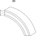
- FIG. 1 is a schematic perspective view of a shape memory morphing member using a Kirigami pattern according to an embodiment of the present disclosure.
- FIG. 2 is a schematic perspective view showing an enlarged core of FIG. 1.
- Figure 3 is a schematic perspective view for explaining that the core of the shape memory morphing member using the Kirigami pattern is stretched in the longitudinal direction according to an embodiment of the present application.
- Figure 4 is a schematic perspective view for explaining the bending deformation of the core of the shape memory morphing member using a Kirigami pattern according to an embodiment of the present application.
- FIG. 5 is a schematic perspective view illustrating that the shape memory morphing member using the Kirigami pattern according to the exemplary embodiment of FIG. 1 is deformed in the longitudinal direction.
- FIG. 6 is a schematic perspective view illustrating a deformation of a shape memory morphing member using a Kirigami pattern according to an exemplary embodiment of the present application in the width direction.
- FIG. 7 is a schematic perspective view illustrating bending deformation of a shape memory morphing member using a Kirigami pattern according to an embodiment of the present disclosure of FIG. 1.
- FIG. 8 is a schematic cross-sectional view of a shape memory morphing member using a Kirigami pattern according to an embodiment of the present application.
- FIG. 9 is a schematic cross-sectional view for describing stacking an upper SMP skin layer and a lower SMP skin layer.
- the present application relates to a shape memory morphing member using a Kirigami pattern.
- the shape memory morphing member (hereinafter referred to as the 'main morphing member') 1000 using the Kirigami pattern will be described.
- Figure 1 is a schematic perspective view of the present morphing member
- Figure 2 is a schematic perspective view showing an enlarged core of Figure 1
- the present morphing member 1000 includes a core 1.
- the core 1 has a Kirigami pattern structure arranged along a length direction and a width direction.
- the longitudinal direction may refer to the 10 o'clock-4 o'clock direction of FIGS. 2 and 3, and the width direction may point to the 1 o'clock-7 o'clock direction of FIGS. 2 and 3.
- the Kirigami pattern structure may be a structure having degrees of freedom for bending deformation, longitudinal deformation, and width deformation.
- the longitudinal deformation means that the core 1 is tensioned in the longitudinal direction (for example, FIG. 3 is relatively tensile) or contracted (for example, FIG. 3 is relatively contracted).
- the widthwise deformation may mean that the core 1 is stretched or shrunk in the width direction.
- the fact that the Kirigami pattern structure has degrees of freedom for bending deformation, longitudinal deformation and widthwise deformation means that the Kirigami pattern structure has bending deformation, longitudinal deformation, and width within a predetermined range in which tension, shrinkage, or bending is possible. It can mean that the direction deformation is possible. For example, referring to FIGS. 2 and 3, the Kirigami pattern structure may be stretched within an unfoldable range.
- the core 1 having the Kirigami pattern structure can be easily bent and deformed in the upper direction and the lower direction, and can be freely stretched or shrunk in the longitudinal direction and the width direction.
- the Kirigami pattern structure includes a Kirigami pattern row 11 that is bent and extended a plurality of times in a form in which the peaks 111 and the valleys 112 are alternately formed along the width direction. It may include a plurality.
- one of the plurality of Kirigami pattern rows 11 includes a mountain portion 111 of the Kirigami pattern row 11 whose portions 111 are adjacent in one direction in the longitudinal direction. It is hinged, and its valley portion 112 may be hinged with the valley portion 112 of the Kirigami pattern row 11 neighboring in the other direction of the longitudinal direction.
- the core 1 may be deformed in the longitudinal direction without being deformed in the width direction. 2 and 4, the core 1 can also be easily bent deformation.
- the present morphing member 1000 includes an upper SMP (Shape Memory Polymer) skin layer 2.
- the present morphing member 1000 includes a lower SMP skin layer 3 disposed below the upper SMP skin layer 2.
- the core 1 described above is interposed between the upper SMP skin layer 2 and the lower SMP skin layer 3.
- the upper SMP skin layer 2, the core 1, and the lower SMP skin layer 3 may form an integrated sandwich structure.
- the present morphing material may be produced by adhering the core 1 of the Kirigami pattern to each of the upper SMP skin layer 2 and the lower SMP skin layer 3 corresponding to the SMP thin film material surface plate.
- the upper SMP skin layer 2 and the lower SMP skin layer 3 have a restoring force to be restored to an initial shape in a first state at a high temperature based on a preset temperature Tg and deformation degrees of freedom corresponding to an external force combined with the restoring force.
- SMP has a characteristic of being restored by memorizing heat softenable materials and a shape before deformation, at a specific temperature (Tg) or more.
- Tg specific temperature
- the upper SMP skin layer 2 and the lower SMP skin layer 3 may be flexible and deformable in the first state, and the shape is restored in accordance with the combination of the restoring force and the external force acting on the first state. Or may be modified.
- the upper and lower SMP skin layers 2 and 3 may not be applied to the upper SMP skin layer 2 and the lower SMP skin layer 3 in addition to the restoring force to be restored to the shape before deformation. ) May be restored to the shape before deformation.
- the shape may be deformed according to the combination of the external force and the restoring force.
- the restoring force to contract in the longitudinal direction is applied to the upper SMP skin layer 2 and the lower SMP skin layer 3 in the first state
- the upper SMP skin layer 2 and the lower SMP skin layer 3 When the external force to extend the length in the longitudinal direction is greater than the restoring force, the upper SMP skin layer 2 and the lower SMP skin layer (3) in the longitudinal direction corresponding to the tensile external force as much as the magnitude of the restoring force from the external force May be tensilely deformed.
- the upper SMP skin layer 2 and the lower SMP skin layer 3 have a vector direction and magnitude in which such restoring force and external force are combined.
- the shape may be deformed in correspondence thereto.
- FIG. 5 is a schematic perspective view showing that the present morphing member of FIG. 1 is deformed in the longitudinal direction
- FIG. 6 is a schematic perspective view showing that the present morphing member of FIG. 1 is deformed in the width direction
- FIG. Fig. 1 is a schematic perspective view showing bending deformation of the present morphing member 1.
- the core is schematically shown in FIGS. 5 to 7.
- the core 1 has a Kirigami pattern structure having degrees of freedom for bending deformation, longitudinal deformation, and widthwise deformation
- the core 1 is compared with each of FIGS. 5 to 7.
- the core 1 In the first state,) may be modified in conjunction with the deformation of the upper SMP skin layer 2 and the deformation of the lower SMP skin layer 3 by the Kirigami pattern structure.
- the present morphing member 1000 is capable of deformation in the longitudinal direction, deformation in the width direction, and bending deformation in the first state.
- zero-poisson's ratio in which the present morphing member 1000 includes only tensile strain in the longitudinal direction without deformation in the width direction may be realized.
- the present morphing member 1000 may implement a negative-poisson's ratio in which the tensile strain in the width direction and the tensile strain in the longitudinal direction are simultaneously performed.
- the morphing member 1000 may be deformed in the width direction in the first state. 1 and 7, the morphing member 1000 may be bent and deformed in the first state. As such, the morphing member 1000 seen in the first state may be one or more of deformation in the longitudinal direction, deformation in the width direction, and bending deformation.
- the morphing member 1000 may be deformed according to a combination of external force and restoring force acting thereon. have. Since the morphing member 1000 has a characteristic of being returned to the shape stored in the first state by the upper SMP skin layer 2 and the lower SMP skin layer 3, the morphing member 1000 returns to the stored shape when no external force is applied. I can go.
- the present morphing member 1000 may maintain the shape that was immediately before the second state (just before leaving the first state). have.
- the upper SMP skin layer 2 and the lower SMP skin layer 3 are the upper SMP skin layer 2 in the first state before being converted to the second state in the second state which is low temperature based on the preset temperature. And the shape of the lower SMP skin layer 3 can be maintained.
- the present morphing member 1000 may be provided with bending stiffness formed by combining the upper SMP skin layer 2, the lower SMP skin layer 3, and the Kirigami pattern structure.
- the upper SMP skin layer 2 and the lower SMP skin layer 3 form a sandwich structure with the core 1 and are integrally bonded, so that they are independent (independently) within a predetermined range (bending strain, tensile strain). Shrinkage deformation) can restrain the deformation of the free core 1.
- the morphing member 1000 seen in the second state has a high bending stiffness due to the mutual coupling relationship between the upper SMP skin layer 2, the lower SMP skin layer 3, and the core 1. Can be built.
- the morphing member 1000 may provide a rigid truss structure by deforming and restraining the upper and lower portions of the core free of deformation in the second state.
- FIG. 8 is a schematic cross-sectional view of the present morphing member
- FIG. 9 is a schematic cross-sectional view for explaining that the upper SMP skin layer and the lower SMP skin layer are stacked.
- the morphing member 1000 has a bending load because the core 1, the upper SMP skin layer 2, and the lower SMP skin layer 3 are arranged in a sandwich structure. It can effectively hold up and have high rigidity.
- the morphing member 1000 (see FIG. 8) and In contrast, the bending stiffness of the present morphing member 1000 due to the core 1 when each of the upper SMP skin layer and the lower SMP skin layer have the same thickness t and the same width w (see FIG. 8). ) Becomes much larger than the bending stiffness of the structure consisting only of the upper SMP skin layer 2 and the lower SMP skin layer 3 (see FIG. 9).
- the present morphing member 1000 includes an upper SMP skin layer 2, a lower SMP skin layer 3, and a core 1 composed of a Kirigami pattern structure, thereby forming different shapes (bending deformation) in the first state. , One or more of deformation in the longitudinal direction, and deformation in the axial direction).
- the present morphing member 1000 lowers the temperatures of the upper SMP skin layer 2 and the lower SMP skin layer 3 to a second state by lowering the temperature below a preset temperature, thereby making the first state before being converted to the second state. The shape at can be maintained.
- the present morphing member 1000 may be continuously deformed through deformation of the Kirigami pattern train.
- the present morphing member 1000 has zero-poisson's ratio in which the length increases only in the longitudinal direction according to the bending degree of the hinge of the Kirigami pattern structure, negative-poisson's ratio and morphing characteristics simultaneously in the longitudinal direction and the width direction. Can be.
- the present morphing member 1000 may have a concise structure since a separate actuator is not required when the shape is deformed unlike the conventional art.
- the present morphing member 1000 is easy to change shape and volume increase and decrease through the Kirigami pattern structure.
- the present morphing member 1000 may withstand a predetermined load or more.
- the present morphing member 1000 is capable of continuous shape deformation. Further, the shape can be modified in all three axes. In addition, the present morphing member 1000 can be deformed by simply changing the temperature of the upper and lower SMP skin layers 2 and 3 without the need for additional actuators such as wires. Accordingly, the morphing member 1000 can be deformed at a lower power than in the related art. In addition, since the SMP skin layer has sandwich structures formed on the upper and lower portions 2 and 3, the shape deformation is easy in the first state and may have high rigidity in the second state.
- the present morphing member 1000 may include a conductor installed to increase or decrease the temperature of the upper SMP skin layer 2 and the lower SMP skin layer 3.
- the conductor By the conductor, the temperature of the upper SMP skin layer 2 and the lower SMP skin layer 3 can be increased or decreased so as to be in the first state or the second state.
- the conductor may be disposed on the inner surface of the upper SMP skin layer 2 and the inner surface of the lower SMP skin layer 3.
- the inner surface of the upper SMP skin layer 2 may mean a surface facing the core 1 of the upper SMP skin layer 2 (drawing reference surface).
- the inner surface of the lower SMP skin layer 3 may refer to a surface (upper reference surface) facing the core 1 of the lower SMP skin layer 3.
- the conductor may be disposed inside the upper SMP skin layer 2 and inside the lower SMP skin layer 3.
- the present morphing member 1000 further includes an upper SMP skin layer 2 and a lower SMP skin layer 3 to increase or decrease the temperature of the upper SMP skin layer 2 and the lower SMP skin layer 3.
- the convection device can adjust the temperature of the gas in correspondence with the first state and the second state.
- a method of increasing or decreasing the temperature of the upper SMP skin layer 2 and the lower SMP skin layer 3 is to install (attach) a conductor or use convection of external air. This can be.
- the present application may provide a morphing wing comprising a morphing member 1000 according to an embodiment of the present application. Accordingly, a morphing wing and an aircraft including the same may be implemented to easily change the shape of the airfoil. When such a morphing wing is applied to an aircraft, an aircraft that can be operated for an improved flight time at a lower power than a conventional aircraft can be implemented.
- the present disclosure may provide a skin of an aircraft including a morphing member 1000 according to an embodiment of the present disclosure.
- an aircraft is provided with a plurality of skins for its skeleton to form wings, fuselage, etc.
- the present morphing member 1000 can be applied to such a skin.
- the present application may provide an aircraft including a morphing member 1000 according to an embodiment of the present application.
Landscapes
- Engineering & Computer Science (AREA)
- Mechanical Engineering (AREA)
- Aviation & Aerospace Engineering (AREA)
- Laminated Bodies (AREA)
Abstract
키리가미 패턴을 이용한 형상기억 모핑 부재가 개시되며, 상기 키리가미 패턴을 이용한 형상기억 모핑 부재는, 상부 SMP 스킨층; 상기 상부 SMP 스킨층의 하측에 배치되는 하부 SMP 스킨층; 및 상기 모핑 부재의 길이 방향과 폭 방향을 따라 키리가미 패턴 구조가 배열되고, 상기 상부 SMP 스킨층과 상기 하부 SMP 스킨층 사이에 개재되는 코어를 포함하되, 상기 상부 SMP 스킨층 및 상기 하부 SMP 스킨층은, 미리 설정된 온도를 기준으로 고온인 제1 상태에서 초기 형상으로 복원되려는 복원력 및 상기 복원력과 조합되는 외력에 대응하는 변형 자유도를 가지고, 상기 미리 설정된 온도를 기준으로 저온인 제2 상태에서는, 상기 제2 상태로 변환되기 전의 상기 제1 상태에서의 상기 상부 SMP 스킨층 및 상기 하부 SMP 스킨층의 형상이 유지된다.
Description
본원은 키리가미 패턴을 이용한 형상기억 모핑 부재에 관한 것이다.
항공기의 효율을 높이고 다양한 운용 조건을 충족시키기 위한 해결책으로 가변 형상 항공기 즉, 모핑 항공기 구조(MAS, Morphing Aircraft Structure)에 대한 연구가 활발하게 진행되고 있다. 예를 들어, 가변 형상을 갖는 모핑 날개의 에어포일에 대한 연구가 활발하게 진행되고 있다.
이와 관련하여, 종래에 항공기의 날개를 기계적으로 형상 변형시키는 기술들이 개시된바 있다. 그런데 개시된 기술들은, 형상 변형이 기계적으로 이루어지기 때문에 많은 에너지가 필요하고, 구조가 복잡하다는 단점을 가지고 있다.
본원의 배경이 되는 기술은 한국등록특허공보 제10-1271485호(등록일 2013년5월30일)에 개시되어 있다.
본원은 전술한 종래 기술의 문제점을 해결하기 위한 것으로서, 별도의 기계적인 작동기의 도움 없이 형상이 변형될 수 있고, 구조적으로 간단하면서도 높은 강성을 가질 수 있는 키리가미 패턴을 이용한 형상기억 모핑 부재를 제공하는 것을 목적으로 한다.
다만, 본원의 실시예가 이루고자 하는 기술적 과제는 상기된 바와 같은 기술적 과제들로 한정되지 않으며, 또 다른 기술적 과제들이 존재할 수 있다.
상기한 기술적 과제를 달성하기 위한 기술적 수단으로서, 본원의 제 1 측면에 따른 키리가미 패턴을 이용한 형상기억 모핑 부재는, 상부 SMP 스킨층; 상기 상부 SMP 스킨층의 하측에 배치되는 하부 SMP 스킨층; 및 상기 모핑 부재의 길이 방향과 폭 방향을 따라 키리가미 패턴 구조가 배열되고, 상기 상부 SMP 스킨층과 상기 하부 SMP 스킨층 사이에 개재되는 코어를 포함하되, 상기 상부 SMP 스킨층 및 상기 하부 SMP 스킨층은, 미리 설정된 온도를 기준으로 고온인 제1 상태에서 초기 형상으로 복원되려는 복원력 및 상기 복원력과 조합되는 외력에 대응하는 변형 자유도를 가지고, 상기 미리 설정된 온도를 기준으로 저온인 제2 상태에서는, 상기 제2 상태로 변환되기 전의 상기 제1 상태에서의 상기 상부 SMP 스킨층 및 상기 하부 SMP 스킨층의 형상이 유지될 수 있다.
상술한 과제 해결 수단은 단지 예시적인 것으로서, 본원을 제한하려는 의도로 해석되지 않아야 한다. 상술한 예시적인 실시예 외에도, 도면 및 발명의 상세한 설명에 추가적인 실시예가 존재할 수 있다.
전술한 본원의 과제 해결 수단에 의하면, 상부 SMP 스킨층과 하부 SMP 스킨층 사이에 키리가미 패턴 구조의 코어가 개재되는 샌드위치 구조를 가짐으로써, 제1 상태에서는 별도의 기계적인 작동기의 도움 없이 형상이 용이하게 변형될 수 있고, 제2 상태에서는 상기 샌드위치 구조가 일체적으로 거동되어 구조적으로 간단하면서도 높은 강성(굽힘 강성)을 가지는 형상기억 모핑 부재가 구현될 수 있다.
도 1은 본원의 일 실시예에 따른 키리가미 패턴을 이용한 형상기억 모핑 부재의 개략적인 사시도이다.
도 2는 도 1의 코어를 확대하여 도시한 개략적인 사시도이다.
도 3은 본원의 일 실시예에 따른 키리가미 패턴을 이용한 형상기억 모핑 부재의 코어가 길이 방향으로 인장되는 것을 설명하기 위한 개략적인 사시도이다.
도 4는 본원의 일 실시예에 따른 키리가미 패턴을 이용한 형상기억 모핑 부재의 코어가 굽힘 변형된 것을 설명하기 위한 개략적인 사시도이다.
도 5는 도 1의 본원의 일 실시예에 따른 키리가미 패턴을 이용한 형상기억 모핑 부재가 길이 방향으로 변형된 것을 도시한 개략적인 사시도이다.
도 6은 도 1의 본원의 일 실시예에 따른 키리가미 패턴을 이용한 형상기억 모핑 부재가 폭 방향으로 변형된 것을 도시한 개략적인 사시도이다.
도 7은 도 1의 본원의 일 실시예에 따른 키리가미 패턴을 이용한 형상기억 모핑 부재가 굽힘 변형된 것을 도시한 개략적인 사시도이다.
도 8은 본원의 일 실시예에 따른 키리가미 패턴을 이용한 형상기억 모핑 부재의 개략적인 단면도이다.
도 9는 상부 SMP 스킨층 및 하부 SMP 스킨층이 적층된 것을 설명하기 위한 개략적인 단면도이다.
아래에서는 첨부한 도면을 참조하여 본원이 속하는 기술 분야에서 통상의 지식을 가진 자가 용이하게 실시할 수 있도록 본원의 실시예를 상세히 설명한다. 그러나 본원은 여러 가지 상이한 형태로 구현될 수 있으며 여기에서 설명하는 실시예에 한정되지 않는다. 그리고 도면에서 본원을 명확하게 설명하기 위해서 설명과 관계없는 부분은 생략하였으며, 명세서 전체를 통하여 유사한 부분에 대해서는 유사한 도면 부호를 붙였다.
본원 명세서 전체에서, 어떤 부분이 다른 부분과 "연결"되어 있다고 할 때, 이는 "직접적으로 연결"되어 있는 경우뿐 아니라, 그 중간에 다른 소자를 사이에 두고 "전기적으로 연결"되어 있는 경우도 포함한다.
본원 명세서 전체에서, 어떤 부재가 다른 부재 "상에", "상부에", "상단에", "하에", "하부에", "하단에" 위치하고 있다고 할 때, 이는 어떤 부재가 다른 부재에 접해 있는 경우뿐 아니라 두 부재 사이에 또 다른 부재가 존재하는 경우도 포함한다.
본원 명세서 전체에서, 어떤 부분이 어떤 구성요소를 "포함" 한다고 할 때, 이는 특별히 반대되는 기재가 없는 한 다른 구성요소를 제외하는 것이 아니라 다른 구성 요소를 더 포함할 수 있는 것을 의미한다.
참고로, 본원의 실시예에 관한 설명 중 방향이나 위치와 관련된 용어(상측, 하측 등)는 도면에 나타나 있는 각 구성의 배치 상태를 기준으로 설정한 것이다. 예를 들면, 도 2에서 보았을 때 전반적으로 12시 방향이 상측, 전반적으로 6시 방향이 하측 등이 될 수 있다.
본원은 키리가미 패턴을 이용한 형상기억 모핑 부재에 관한 것이다.
이하에서는 본원의 일 실시예에 따른 키리가미 패턴을 이용한 형상기억 모핑 부재(이하 '본 모핑 부재'라 함)(1000)에 대해 설명한다.
도 1은 본 모핑 부재의 개략적인 사시도이고, 도 2는 도 1의 코어를 확대하여 도시한 개략적인 사시도이며, 도 3은 본 모핑 부재의 코어가 길이 방향으로 인장되는 것을 설명하기 위한 개략적인 사시도이고, 도 4는 본 모핑 부재의 코어가 굽힘 변형된 것을 설명하기 위한 개략적인 사시도이다.
도 1을 참조하면, 본 모핑 부재(1000)는 코어(1)를 포함한다. 도 2를 참조하면, 코어(1)는 길이 방향과 폭 방향을 따라 키리가미(Kirigami) 패턴 구조가 배열된 것이다. 참고로, 길이 방향은 도 2 및 도 3 기준 10시-4시 방향, 폭 방향은 도 2 및 도 3 기준 1시-7시 방향을 가리키는 것일 수 있다.
도 2를 도 3 및 도 4 각각과 비교하여 참고하면, 키리가미 패턴 구조는 굽힘 변형, 길이 방향 변형 및 폭 방향 변형에 대한 자유도를 갖는 구조일 수 있다.
여기서 길이 방향 변형이라 함은 코어(1)가 길이 방향으로 인장(예를 들어 도 2 대비 도 3은 상대적으로 인장 상태) 또는 수축(예를 들어 도 3 대비 도 2는 상대적으로 수축 상태)되는 것을 의미할 수 있다. 또한, 폭 방향 변형은 코어(1)가 폭 방향으로 인장 또는 수축되는 것을 의미할 수 있다. 또한, 키리가미 패턴 구조가 굽힘 변형, 길이 방향 변형 및 폭 방향 변형에 대한 자유도를 갖는다는 것은 키리가미 패턴 구조가 인장, 수축, 또는 굽힘이 가능한 소정의 범위 내에서 굽힘 변형, 길이 방향 변형 및 폭 방향 변형이 가능한 것을 의미할 수 있다. 예시적으로 도 2 및 도 3을 참조하면, 키리가미 패턴 구조는 펼침 가능한 범위 내에서 인장될 수 있다.
이와 같이 키리가미 패턴 구조를 갖는 코어(1)는 상측 방향 및 하측 방향으로 용이하게 구부러지며 형상 변형될 수 있고, 길이 방향 및 폭 방향으로 자유롭게 인장 또는 수축될 수 있다.
예시적으로, 도 2를 참조하면, 키리가미 패턴 구조는, 폭 방향을 따라 산(111)과 골(112)이 교번하여 형성되는 형태로 복수 회 절곡되며 연장되는 키리가미 패턴 열(11)을 복수개 포함할 수 있다.
또한, 도 2를 참조하면, 복수개의 키리가미 패턴 열(11) 중 하나는, 그의 산(111) 부분이 길이 방향 중 일 방향으로 이웃하는 키리가미 패턴 열(11)의 산 부분(111)과 힌지 결합되고, 그의 골 부분(112)이 길이 방향 중 타 방향으로 이웃하는 키리가미 패턴 열(11)의 골 부분(112)과 힌지 결합될 수 있다.
도 2와 도 3을 대비하여 보면, 이러한 키리가미 패턴 구조에 의하면, 코어(1)는 폭 방향으로의 변형 없이 길이 방향으로의 변형이 이루어질 수 있다. 또한 도 2와 도 4를 대비하여 보면, 코어(1)는 굽힘 변형도 용이하게 이루어질 수 있다.
또한, 도 1을 참조하면, 본 모핑 부재(1000)는 상부 SMP(형상 기억 폴리머, Shape Memory Polymer) 스킨층(2)을 포함한다. 또한, 본 모핑 부재(1000)는 상부 SMP 스킨층(2)의 하측에 배치되는 하부 SMP 스킨층(3)을 포함한다. 상술한 코어(1)는 상부 SMP 스킨층(2)과 하부 SMP 스킨층(3) 사이에 개재된다.
상부 SMP 스킨층(2), 코어(1), 및 하부 SMP 스킨층(3)은 일체화된 샌드위치 구조를 형성할 수 있다. 이를테면, 본 모핑 재료는 SMP 박막 재료 표면 판에 해당하는 상부 SMP 스킨층(2) 및 하부 SMP 스킨층(3) 각각에 키리가미 패턴의 코어(1)가 접착됨으로써 제조될 수 있다.
상부 SMP 스킨층(2) 및 하부 SMP 스킨층(3)은 미리 설정된 온도(Tg)를 기준으로 고온인 제1 상태에서 초기 형상으로 복원되려는 복원력 및 상기 복원력과 조합되는 외력에 대응하는 변형 자유도를 가질 수 있다.
구체적으로, SMP는 특정온도(Tg) 이상에서 유연해지는 특성(heat softenable materials) 및 변형 전의 형상을 기억하여 복원되려는 특성이 있다. 이에 따르면, 상부 SMP 스킨층(2) 및 하부 SMP 스킨층(3)은 제1 상태에서 유연해져 변형 가능한 상태가 될 수 있고, 제1 상태에서 복원력 및 그에 작용하는 외력의 조합에 따라 형상이 복원되거나 변형될 수 있다.
예시적으로, 제1 상태에서 상부 SMP 스킨층(2) 및 하부 SMP 스킨층(3)에 변형 전의 형상으로 복원되려는 복원력 외에 별도의 외력이 작용하지 않으면, 상부 및 하부 SMP 스킨층(2, 3)은 변형 전의 형상으로 복원될 수 있다.
또한, 상부 SMP 스킨층(2) 및 하부 SMP 스킨층(3)은 제1 상태에서 유연해져 변형 가능한 상태가 되므로, 제1 상태에서 외력이 작용하면 외력과 복원력의 조합에 따라 형상이 변형될 수 있다. 예를 들어, 제1 상태에서 상부 SMP 스킨층(2) 및 하부 SMP 스킨층(3)에 길이 방향으로 수축되려는 복원력이 작용될 때, 상부 SMP 스킨층(2) 및 하부 SMP 스킨층(3)을 길이 방향으로 인장시키려는 외력이 상기 복원력보다 크게 가해지게 되면, 상기 외력에서 상기 복원력만큼을 감한 크기만큼의 인장 외력에 대응하여 상부 SMP 스킨층(2) 및 하부 SMP 스킨층(3)이 길이 방향으로 인장 변형될 수 있을 것이다. 다른 예로, 제1 상태에서 복원력은 길이 방향으로 작용되고 외력은 굽힘 방향으로 작용되는 경우, 상부 SMP 스킨층(2)과 하부 SMP 스킨층(3)은 이러한 복원력과 외력이 조합된 벡터 방향 및 크기에 대응하여 형상이 변형될 수 있을 것이다.
도 5는 도 1의 본 모핑 부재가 길이 방향으로 변형된 것을 도시한 개략적인 사시도이고, 도 6은 도 1의 본 모핑 부재가 폭 방향으로 변형된 것을 도시한 개략적인 사시도이며, 도 7은 도 1의 본 모핑 부재가 굽힘 변형된 것을 도시한 개략적인 사시도이다. 참고로, 도 5 내지 도 7에서 코어는 개략적으로 도시되었다.
상술한 바와 같이, 코어(1)는 굽힘 변형, 길이 방향 변형 및 폭 방향 변형에 대한 자유도를 갖는 키리가미 패턴 구조를 가지므로, 도 1을 도 5 내지 도 7 각각과 대비하여 보면, 코어(1)는 제1 상태에서 키리가미 패턴 구조에 의해 상부 SMP 스킨층(2)의 변형 및 하부 SMP 스킨층(3)의 변형과 연동하는 변형을 할 수 있다. 이에 따라, 본 모핑 부재(1000)는 제1 상태에서 길이 방향으로의 변형, 폭 방향으로의 변형 및 굽힘 변형이 가능하다.
이에 따라, 도 1과 도 5를 대비하여 보면, 제1 상태에서 키리가미 패턴 구조에 의하면, 본 모핑 부재(1000)가 폭 방향의 변형 없이 길이 방향의 인장 변형만 이루어지는 zero-poisson's ratio가 구현될 수 있다. 또한, 제1 상태에서 키리가미 패턴 구조에 의하면, 본 모핑 부재(1000)가 폭 방향의 인장 변형 및 길이 방향의 인장 변형이 동시에 이루어지는 negative-poisson's ratio의 구현이 가능하다.
또한, 도 1과 도 6을 대비하여 보면, 본 모핑 부재(1000)는 제1 상태에서 폭 방향으로의 변형이 가능하다. 또한, 도 1과 도 7을 대비하여 보면, 본 모핑 부재(1000)는 제1 상태에서 굽힘 변형이 가능하다. 이와 같이, 제1 상태에서 본 모핑 부재(1000)는 길이 방향으로의 변형, 폭 방향으로의 변형 및 굽힘 변형 중 하나 이상이 가능하다.
이와 같이, 상부 및 하부 SMP 스킨층(2, 3)의 온도가 증가되어 제1 상태가 되면 본 모핑 부재(1000)는 형상 변형이 가능하여 그에 작용하는 외력과 복원력의 조합에 따라 형상 변형될 수 있다. 본 모핑 부재(1000)는 상부 SMP 스킨층(2) 및 하부 SMP 스킨층( 3)에 의해, 제1 상태에서 기억된 형상으로 되돌아가려는 특성을 가지므로, 외력이 작용하지 않으면 기억된 형상으로 되돌아갈 수 있다.
또한, 상부 및 하부 SMP 스킨층(2, 3)의 온도가 감소되어 제2 상태가 되면 본 모핑 부재(1000)는 제2 상태가 되기 직전(제1 상태를 벗어나기 직전)에 가졌던 형상을 유지할 수 있다.
구체적으로, 상부 SMP 스킨층(2) 및 하부 SMP 스킨층(3)은 미리 설정된 온도를 기준으로 저온인 제2 상태에서는 제2 상태로 변환되기 전의 제1 상태에서의 상부 SMP 스킨층(2) 및 하부 SMP 스킨층(3)의 형상이 유지될 수 있다.
이에 따라, 제2 상태에서, 본 모핑 부재(1000)에는 상부 SMP 스킨층(2) 및 하부 SMP 스킨층(3)과 키리가미 패턴 구조가 조합되어 형성되는 굽힘 강성이 제공될 수 있다. 상부 SMP 스킨층(2) 및 하부 SMP 스킨 층(3)은 코어(1)와 샌드위치 구조를 이루며 일체적으로 결합됨으로써, 단독(독립)적으로는 소정의 범위 내에서 변형(굽힘 변형, 인장 변형, 수축 변형)이 자유로운코어(1)의 변형을 구속할 수 있다. 나아가, 제2 상태에서 본 모핑 부재(1000)는 상부 SMP 스킨층(2), 하부 SMP 스킨 층(3) 및 코어(1)의 상호 결합 관계에 의해, 높은 굽힘 강성(bending stiffness)을 가지는 구조를 구축할 수 있다. 본 모핑 부재(1000)는 제2 상태에서 변형이 자유로운 코어의 상부와 하부가 변형 구속됨으로써 강결(rigid) 트러스 구조를 제공할 수 있다.
도 8은 본 모핑 부재의 개략적인 단면도이고, 도 9는 상부 SMP 스킨층 및 하부 SMP 스킨층이 적층된 것을 설명하기 위한 개략적인 단면도이다.
도 8을 참조하면, 상술한 바와 같이, 본 모핑 부재(1000)는 코어(1), 상부 SMP 스킨층(2) 및 하부 SMP 스킨층(3)이 샌드위치 구조로 배치된 구조이기 때문에 굽힘 하중을 효과적으로 버틸 수 있고 높은 강성을 가질 수 있다.
예를 들어, 코어(1)를 제외하고 상부 SMP 스킨층(2) 및 하부 SMP 스킨층(3)으로만 이루어지는 구조의 경우(도 9 참조)를 본 모핑 부재(1000)(도 8 참조)와 대비하여 보면, 각각의 상부 SMP 스킨층 및 하부 SMP 스킨층이 같은 두께(t) 및 같은 폭(w)을 가진다고 하였을 때 코어(1)로 인해 본 모핑 부재(1000)의 굽힘 강성(도 8 참조)은 상부 SMP 스킨층(2) 및 하부 SMP 스킨층(3)으로만 이루어지는 구조(도 9 참조)의 굽힘 강성보다 훨씬 커지게 된다.
정리하면, 본 모핑 부재(1000)는, 상부 SMP 스킨층(2), 하부 SMP 스킨층(3), 및 키리가미 패턴 구조로 이루어진 코어(1)를 포함함으로써 제1 상태에서 다른 형상(굽힘 변형, 길이 방향으로의 변형, 및 축 방향으로의 변형 중 하나 이상)으로 용이하게 변형될 수 있다. 또한, 본 모핑 부재(1000)는 상부 SMP 스킨층(2) 및 하부 SMP 스킨층(3)의 온도를 미리 설정된 온도 이하로 낮추어 제2 상태가 되게 함으로써, 제2 상태로 변환되기 전의 제1 상태에서의 형상을 유지할 수 있다.
이와 같은 본 모핑 부재(1000)는 키리가미 패턴 열의 변형을 통해 연속적인 변형이 가능하다. 또한, 본 모핑 부재(1000)는 키리가미 패턴 구조가 갖는 힌지의 굽힘 정도에 따라 길이방향으로만 길이가 늘어나는 zero-poisson's ratio, 길이방향과 폭방향으로 동시에 늘어나는 negative-poisson's ratio 및 모핑 특성을 가질 수 있다. 또한, 본 모핑 부재(1000)는 종래와 달리 형상 변형 시 별도의 작동기가 필요하지 않으므로 간명한 구조를 가질 수 있다. 또한, 본 모핑 부재(1000)는 키리가미 패턴 구조를 통해 형상 변환 및 부피 증감이 용이하다. 또한, 본 모핑 부재(1000)는 일정 이상의 하중을 버틸 수 있다.
또한, 본 모핑 부재(1000)는 연속적인 형상 변형이 가능하다. 또한, 3축 모든 방향으로 형상 변형 가능하다. 또한, 본 모핑 부재(1000)는 와이어와 같은 추가적인 작동기의 필요 없이 단순히 상부 및 하부 SMP 스킨층(2, 3)의 온도 변화로 형상이 변형될 수 있다. 이에 따라, 종래에 비해 본 모핑 부재(1000)는 저전력으로 형상 변형이 가능하다. 또한, SMP 스킨층이 상부 및 하부(2, 3)에 형성되는 샌드위치 구조를 갖기 때문에 제1 상태에서는 형상 변형이 용이하고 제2 상태에서는 높은 강성을 가질 수 있다.
또한, 본 모핑 부재(1000)는 상부 SMP 스킨층(2), 및 하부 SMP 스킨층(3)의 온도를 증가 또는 감소시키도록 설치되는 전도체를 포함할 수 있다. 전도체에 의해 상부 SMP 스킨층(2), 및 하부 SMP 스킨층(3)의 온도는 증가 또는 감소될 수 있어 제1 상태 또는 제2 상태가 될 수 있다.
예시적으로, 전도체는 상부 SMP 스킨층(2)의 내면 및 하부 SMP 스킨층(3)의 내면에 배치될 수 있다. 여기서, 상부 SMP 스킨층(2)의 내면은 상부 SMP 스킨층(2)의 코어(1)를 향하는 면(도면 기준 하면)을 의미할 수 있다. 또한, 하부 SMP 스킨층(3)의 내면은 하부 SMP 스킨층(3)의 코어(1)를 향하는 면(도면 기준 상면)을 의미할 수 있다. 또는, 전도체는 상부 SMP 스킨층(2)의 내부 및 하부 SMP 스킨층(3)의 내부에 배치될 수 있다.
또한 다른 구현예로서, 본 모핑 부재(1000)는 상부 SMP 스킨층(2) 및 하부 SMP 스킨층(3)의 온도를 증가 또는 감소시키도록 상부 SMP 스킨층(2) 및 하부 SMP 스킨층(3) 주변에 기체를 대류시키는 대류 장치를 포함할 수 있다. 대류 장치는 기체의 온도를 제1 상태 및 제2 상태에 대응하여 조절 가능하다.
즉, 본 모핑 부재(1000)에 있어서, 상부 SMP 스킨층(2) 및 하부 SMP 스킨층(3)의 온도를 증가 또는 감소시키는 방법으로는 전도체를 설치(부착)하거나 외부 공기의 대류를 이용하는 방법이 있을 수 있다.
또한, 본원은 본원의 일 실시예에 따른 모핑 부재(1000)를 포함하는 모핑 날개를 제공할 수 있다. 이에 따라, 에어포일의 형상이 용이하게 변경되는 모핑 날개 및 이를 포함하는 항공기가 구현될 수 있다. 이러한 모핑 날개가 항공기에 적용되면, 기존의 항공기에 비해 저전력으로 향상된 비행 시간 동안 운항될 수 있는 항공기가 구현될 수 있다.
또한, 본원은 본원의 일 실시예에 따른 모핑 부재(1000)를 포함하는 항공기의 스킨을 제공할 수 있다. 일반적으로, 항공기는 그 골격에 대해 다수의 스킨이 구비됨으로써 날개, 동체 등이 형성된다, 본 모핑 부재(1000)는 이러한 스킨에 적용될 수 있다. 또한, 본원은 본원의 일 실시예에 따른 모핑 부재(1000)를 포함하는 항공기를 제공할 수 있다.
전술한 본원의 설명은 예시를 위한 것이며, 본원이 속하는 기술분야의 통상의 지식을 가진 자는 본원의 기술적 사상이나 필수적인 특징을 변경하지 않고서 다른 구체적인 형태로 쉽게 변형이 가능하다는 것을 이해할 수 있을 것이다. 그러므로 이상에서 기술한 실시예들은 모든 면에서 예시적인 것이며 한정적이 아닌 것으로 이해해야만 한다. 예를 들어, 단일형으로 설명되어 있는 각 구성 요소는 분산되어 실시될 수도 있으며, 마찬가지로 분산된 것으로 설명되어 있는 구성 요소들도 결합된 형태로 실시될 수 있다.
본원의 범위는 상기 상세한 설명보다는 후술하는 특허청구범위에 의하여 나타내어지며, 특허청구범위의 의미 및 범위 그리고 그 균등 개념으로부터 도출되는 모든 변경 또는 변형된 형태가 본원의 범위에 포함되는 것으로 해석되어야 한다.
Claims (11)
- 모핑 부재에 있어서,상부 SMP 스킨층;상기 상부 SMP 스킨층의 하측에 배치되는 하부 SMP 스킨층; 및상기 모핑 부재의 길이 방향과 폭 방향을 따라 키리가미 패턴 구조가 배열되고, 상기 상부 SMP 스킨층과 상기 하부 SMP 스킨층 사이에 개재되는 코어를 포함하되,상기 상부 SMP 스킨층 및 상기 하부 SMP 스킨층은, 미리 설정된 온도를 기준으로 고온인 제1 상태에서 초기 형상으로 복원되려는 복원력 및 상기 복원력과 조합되는 외력에 대응하는 변형 자유도를 가지고,상기 미리 설정된 온도를 기준으로 저온인 제2 상태에서는, 상기 제2 상태로 변환되기 전의 상기 제1 상태에서의 상기 상부 SMP 스킨층 및 상기 하부 SMP 스킨층의 형상이 유지되는 것인, 키리가미 패턴을 이용한 형상기억 모핑 부재.
- 제1항에 있어서,상기 상부 SMP 스킨층, 상기 코어, 및 상기 하부 SMP 스킨층은 일체화된 샌드위치 구조를 형성하는 것인, 키리가미 패턴을 이용한 형상기억 모핑 부재.
- 제1항에 있어서,상기 제2 상태에서, 상기 모핑 부재에는 상기 상부 SMP 스킨층 및 상기 하부 SMP 스킨층과 키리가미 패턴 구조가 조합되어 형성되는 굽힘 강성이 제공되는 것인, 키리가미 패턴을 이용한 형상기억 모핑 부재.
- 제1항에 있어서,상기 키리가미 패턴 구조는, 굽힘 변형, 길이 방향 변형 및 폭 방향 변형에 대한 자유도를 갖는 구조인 것인, 키리가미 패턴을 이용한 형상기억 모핑 부재.
- 제1항에 있어서,상기 키리가미 패턴 구조는, 폭 방향을 따라 산과 골이 교번하여 형성되는 형태로 복수 회 절곡되며 연장되는 키리가미 패턴 열을 복수개 포함하고,복수개의 상기 키리가미 패턴 열 중 하나는, 그의 산 부분이 길이 방향 중 일 방향으로 이웃하는 키리가미 패턴 열의 산 부분과 힌지 결합되고, 그의 골 부분이 길이 방향 중 타 방향으로 이웃하는 키리가미 패턴 열의 골 부분과 힌지 결합되는 것인, 키리가미 패턴을 이용한 형상기억 모핑 부재.
- 제1항에 있어서,상기 제1 상태에서 상기 키리가미 패턴 구조에 의하면,상기 모핑 부재가 폭 방향의 변형 없이 길이 방향의 인장 변형만 이루어지는 zero-poisson's ratio 및 상기 모핑 부재가 폭 방향의 인장 변형 및 길이 방향의 인장 변형이 동시에 이루어지는 negative-poisson's ratio의 구현이 가능한 것인, 키리가미 패턴을 이용한 형상기억 모핑 부재.
- 제1항에 있어서,상기 상부 SMP 스킨층 및 상기 하부 SMP 스킨층의 온도를 증가 또는 감소시키도록 설치되는 전도체를 더 포함하는, 키리가미 패턴을 이용한 형상기억 모핑 부재.
- 제7항에 있어서,상기 전도체는 상기 상부 SMP 스킨층의 내면 또는 내부 및 상기 하부 SMP 스킨층의 내면 또는 내부에 배치되는 것인, 키리가미 패턴을 이용한 형상기억 모핑 부재.
- 제1항에 있어서,상기 상부 SMP 스킨층 및 상기 하부 SMP 스킨층의 온도를 증가 또는 감소시키도록 상기 상부 SMP 스킨층 및 상기 하부 SMP 스킨층 주변에 기체를 대류시키는 대류 장치를 더 포함하고,상기 대류 장치는 상기 기체의 온도를 상기 제1 상태 및 상기 제2 상태에 대응하여 조절 가능한 것인, 키리가미 패턴을 이용한 형상기억 모핑 부재.
- 제1항에 따른 키리가미 패턴을 이용한 형상기억 모핑 부재를 포함하는 모핑 날개.
- 제1항에 따른 키리가미 패턴을 이용한 형상기억 모핑 부재를 포함하는 항공기의 스킨.
Priority Applications (1)
| Application Number | Priority Date | Filing Date | Title |
|---|---|---|---|
| EP17893081.4A EP3549855B1 (en) | 2017-01-17 | 2017-11-20 | Shape memory morphing member using kirigami pattern |
Applications Claiming Priority (2)
| Application Number | Priority Date | Filing Date | Title |
|---|---|---|---|
| KR1020170007921A KR101903454B1 (ko) | 2017-01-17 | 2017-01-17 | 키리가미 패턴을 이용한 형상기억 모핑 부재 |
| KR10-2017-0007921 | 2017-01-17 |
Publications (1)
| Publication Number | Publication Date |
|---|---|
| WO2018135739A1 true WO2018135739A1 (ko) | 2018-07-26 |
Family
ID=62908596
Family Applications (1)
| Application Number | Title | Priority Date | Filing Date |
|---|---|---|---|
| PCT/KR2017/013200 Ceased WO2018135739A1 (ko) | 2017-01-17 | 2017-11-20 | 키리가미 패턴을 이용한 형상기억 모핑 부재 |
Country Status (3)
| Country | Link |
|---|---|
| EP (1) | EP3549855B1 (ko) |
| KR (1) | KR101903454B1 (ko) |
| WO (1) | WO2018135739A1 (ko) |
Cited By (1)
| Publication number | Priority date | Publication date | Assignee | Title |
|---|---|---|---|---|
| CN113267092A (zh) * | 2021-06-02 | 2021-08-17 | 哈尔滨工业大学 | 一种偏转弹头变形蒙皮结构 |
Families Citing this family (2)
| Publication number | Priority date | Publication date | Assignee | Title |
|---|---|---|---|---|
| KR102343337B1 (ko) | 2020-06-23 | 2021-12-23 | 한국항공대학교산학협력단 | 제로 포아송 비를 갖는 신축성 형상기억 폴리머 복합재 스킨 |
| CN116504344B (zh) * | 2023-04-28 | 2026-01-06 | 西南大学 | 一种基于剪纸胞元模式的柱类薄壁结构负泊松比化超材料及其设计方法 |
Citations (5)
| Publication number | Priority date | Publication date | Assignee | Title |
|---|---|---|---|---|
| US6182929B1 (en) * | 1997-09-25 | 2001-02-06 | Daimlerchrysler Ag | Load carrying structure having variable flexibility |
| US7931240B2 (en) * | 2006-08-11 | 2011-04-26 | Techno-Sciences, Inc. | Cellular support structures used for controlled actuation of fluid contact surfaces |
| US20110300358A1 (en) * | 2010-06-04 | 2011-12-08 | The Boeing Company | Shape memory alloy/fiber reinforced polymeric composite structures and method for forming |
| JP2012517922A (ja) * | 2009-03-27 | 2012-08-09 | レイセオン カンパニー | 形状変化材料および方法 |
| KR101271485B1 (ko) | 2011-12-23 | 2013-06-05 | 한국항공우주연구원 | 항공기 모핑 날개 |
Family Cites Families (3)
| Publication number | Priority date | Publication date | Assignee | Title |
|---|---|---|---|---|
| AU2002323407A1 (en) * | 2001-08-24 | 2003-03-10 | University Of Virginia Patent Foundation | Reversible shape memory multifunctional structural designs and method of using and making the same |
| US7678440B1 (en) * | 2006-03-01 | 2010-03-16 | Mcknight Geoffrey P | Deformable variable-stiffness cellular structures |
| US8815054B2 (en) * | 2012-10-05 | 2014-08-26 | The Procter & Gamble Company | Methods for making fibrous paper structures utilizing waterborne shape memory polymers |
-
2017
- 2017-01-17 KR KR1020170007921A patent/KR101903454B1/ko not_active Expired - Fee Related
- 2017-11-20 EP EP17893081.4A patent/EP3549855B1/en not_active Not-in-force
- 2017-11-20 WO PCT/KR2017/013200 patent/WO2018135739A1/ko not_active Ceased
Patent Citations (5)
| Publication number | Priority date | Publication date | Assignee | Title |
|---|---|---|---|---|
| US6182929B1 (en) * | 1997-09-25 | 2001-02-06 | Daimlerchrysler Ag | Load carrying structure having variable flexibility |
| US7931240B2 (en) * | 2006-08-11 | 2011-04-26 | Techno-Sciences, Inc. | Cellular support structures used for controlled actuation of fluid contact surfaces |
| JP2012517922A (ja) * | 2009-03-27 | 2012-08-09 | レイセオン カンパニー | 形状変化材料および方法 |
| US20110300358A1 (en) * | 2010-06-04 | 2011-12-08 | The Boeing Company | Shape memory alloy/fiber reinforced polymeric composite structures and method for forming |
| KR101271485B1 (ko) | 2011-12-23 | 2013-06-05 | 한국항공우주연구원 | 항공기 모핑 날개 |
Non-Patent Citations (2)
| Title |
|---|
| NEVILLE ET AL.: "Shape Morphing Kirigami Mechanical Metamaterials", SCIENTIFIC REPORTS 6, vol. 6, no. 1, 5 August 2016 (2016-08-05), pages 1 - 11, XP055504831 * |
| See also references of EP3549855A4 |
Cited By (2)
| Publication number | Priority date | Publication date | Assignee | Title |
|---|---|---|---|---|
| CN113267092A (zh) * | 2021-06-02 | 2021-08-17 | 哈尔滨工业大学 | 一种偏转弹头变形蒙皮结构 |
| CN113267092B (zh) * | 2021-06-02 | 2022-07-15 | 哈尔滨工业大学 | 一种偏转弹头变形蒙皮结构 |
Also Published As
| Publication number | Publication date |
|---|---|
| EP3549855B1 (en) | 2022-08-03 |
| EP3549855A1 (en) | 2019-10-09 |
| KR20180084383A (ko) | 2018-07-25 |
| EP3549855A4 (en) | 2020-08-12 |
| KR101903454B1 (ko) | 2018-10-02 |
Similar Documents
| Publication | Publication Date | Title |
|---|---|---|
| US7931240B2 (en) | Cellular support structures used for controlled actuation of fluid contact surfaces | |
| JP5627636B2 (ja) | 機械的メタ材料 | |
| US8186631B2 (en) | Aerofoil member | |
| US6423895B1 (en) | Solar array for satellite vehicles | |
| US20020040726A1 (en) | Roll-out solar generator with a roll-out array structure and method of using same | |
| KR101729702B1 (ko) | 입체 배열구조를 갖는 신축성 에너지 저장소자 및 신축성 전자 디바이스 | |
| US20060163431A1 (en) | Cover skin for a variable-shape aerodynamic area | |
| EP3390756B1 (en) | Variable length screen, system comprising the same and method for manufacturing | |
| US7154362B2 (en) | Robotic member | |
| US11374533B2 (en) | Solar power generation paddle, method of manufacturing the same, and space structure | |
| CA2765616A1 (en) | Extendable structure | |
| CN111547273B (zh) | 薄膜航天器 | |
| CN107757860A (zh) | 基于气动肌肉的主动变形蜂窝结构蒙皮 | |
| US5922446A (en) | Structural members with large unidirectional rigidities | |
| Li et al. | A flexible morphing wing by soft wing skin actuation utilizing dielectric elastomer: Experiments and electro-aerodynamic model | |
| KR101903454B1 (ko) | 키리가미 패턴을 이용한 형상기억 모핑 부재 | |
| KR102279067B1 (ko) | 신축성 기판 및 그 제조 방법 | |
| US5434464A (en) | Unidirectional supporting structure for microelectromechanical transducers | |
| JP2024528074A5 (ko) | ||
| WO2020162864A1 (en) | Electronic display devices | |
| WO2020085611A1 (ko) | 레이어 재밍 구동장치 | |
| WO2021261676A1 (ko) | 제로 포아송 비를 갖는 신축성 형상기억 폴리머 복합재 스킨 | |
| US12334865B2 (en) | Passively deployable solar panel array with truss backing and synchronizing linkages | |
| EP4496215A1 (en) | Expandable solar cell paddle | |
| WO2022158867A1 (ko) | 복합체 제조방법 및 이에 의해 제조된 복합체 |
Legal Events
| Date | Code | Title | Description |
|---|---|---|---|
| 121 | Ep: the epo has been informed by wipo that ep was designated in this application |
Ref document number: 17893081 Country of ref document: EP Kind code of ref document: A1 |
|
| ENP | Entry into the national phase |
Ref document number: 2017893081 Country of ref document: EP Effective date: 20190703 |
|
| NENP | Non-entry into the national phase |
Ref country code: DE |