WO2018137577A1 - 通信方法及装置 - Google Patents
通信方法及装置 Download PDFInfo
- Publication number
- WO2018137577A1 WO2018137577A1 PCT/CN2018/073583 CN2018073583W WO2018137577A1 WO 2018137577 A1 WO2018137577 A1 WO 2018137577A1 CN 2018073583 W CN2018073583 W CN 2018073583W WO 2018137577 A1 WO2018137577 A1 WO 2018137577A1
- Authority
- WO
- WIPO (PCT)
- Prior art keywords
- configuration information
- indicate
- frequency domain
- control information
- network device
- Prior art date
- Legal status (The legal status is an assumption and is not a legal conclusion. Google has not performed a legal analysis and makes no representation as to the accuracy of the status listed.)
- Ceased
Links
Images


Classifications
-
- H—ELECTRICITY
- H04—ELECTRIC COMMUNICATION TECHNIQUE
- H04L—TRANSMISSION OF DIGITAL INFORMATION, e.g. TELEGRAPHIC COMMUNICATION
- H04L5/00—Arrangements affording multiple use of the transmission path
- H04L5/0091—Signalling for the administration of the divided path, e.g. signalling of configuration information
- H04L5/0094—Indication of how sub-channels of the path are allocated
-
- H—ELECTRICITY
- H04—ELECTRIC COMMUNICATION TECHNIQUE
- H04L—TRANSMISSION OF DIGITAL INFORMATION, e.g. TELEGRAPHIC COMMUNICATION
- H04L5/00—Arrangements affording multiple use of the transmission path
- H04L5/003—Arrangements for allocating sub-channels of the transmission path
- H04L5/0053—Allocation of signalling, i.e. of overhead other than pilot signals
-
- H—ELECTRICITY
- H04—ELECTRIC COMMUNICATION TECHNIQUE
- H04L—TRANSMISSION OF DIGITAL INFORMATION, e.g. TELEGRAPHIC COMMUNICATION
- H04L1/00—Arrangements for detecting or preventing errors in the information received
-
- H—ELECTRICITY
- H04—ELECTRIC COMMUNICATION TECHNIQUE
- H04L—TRANSMISSION OF DIGITAL INFORMATION, e.g. TELEGRAPHIC COMMUNICATION
- H04L1/00—Arrangements for detecting or preventing errors in the information received
- H04L1/0001—Systems modifying transmission characteristics according to link quality, e.g. power backoff
- H04L1/0023—Systems modifying transmission characteristics according to link quality, e.g. power backoff characterised by the signalling
- H04L1/0027—Scheduling of signalling, e.g. occurrence thereof
-
- H—ELECTRICITY
- H04—ELECTRIC COMMUNICATION TECHNIQUE
- H04L—TRANSMISSION OF DIGITAL INFORMATION, e.g. TELEGRAPHIC COMMUNICATION
- H04L5/00—Arrangements affording multiple use of the transmission path
- H04L5/003—Arrangements for allocating sub-channels of the transmission path
-
- H—ELECTRICITY
- H04—ELECTRIC COMMUNICATION TECHNIQUE
- H04L—TRANSMISSION OF DIGITAL INFORMATION, e.g. TELEGRAPHIC COMMUNICATION
- H04L5/00—Arrangements affording multiple use of the transmission path
- H04L5/003—Arrangements for allocating sub-channels of the transmission path
- H04L5/0048—Allocation of pilot signals, i.e. of signals known to the receiver
-
- H—ELECTRICITY
- H04—ELECTRIC COMMUNICATION TECHNIQUE
- H04W—WIRELESS COMMUNICATION NETWORKS
- H04W72/00—Local resource management
- H04W72/04—Wireless resource allocation
-
- H—ELECTRICITY
- H04—ELECTRIC COMMUNICATION TECHNIQUE
- H04W—WIRELESS COMMUNICATION NETWORKS
- H04W72/00—Local resource management
- H04W72/20—Control channels or signalling for resource management
- H04W72/23—Control channels or signalling for resource management in the downlink direction of a wireless link, i.e. towards a terminal
-
- H—ELECTRICITY
- H04—ELECTRIC COMMUNICATION TECHNIQUE
- H04L—TRANSMISSION OF DIGITAL INFORMATION, e.g. TELEGRAPHIC COMMUNICATION
- H04L5/00—Arrangements affording multiple use of the transmission path
- H04L5/003—Arrangements for allocating sub-channels of the transmission path
- H04L5/0058—Allocation criteria
- H04L5/0064—Rate requirement of the data, e.g. scalable bandwidth, data priority
-
- H—ELECTRICITY
- H04—ELECTRIC COMMUNICATION TECHNIQUE
- H04L—TRANSMISSION OF DIGITAL INFORMATION, e.g. TELEGRAPHIC COMMUNICATION
- H04L5/00—Arrangements affording multiple use of the transmission path
- H04L5/003—Arrangements for allocating sub-channels of the transmission path
- H04L5/0058—Allocation criteria
- H04L5/0073—Allocation arrangements that take into account other cell interferences
Definitions
- the embodiments of the present application relate to communication technologies, and in particular, to a communication method and apparatus.
- the embodiment of the present application provides a communication method and device, so as to improve flexibility of resource allocation.
- the application provides a communication method, including:
- the terminal receives the configuration information sent by the network device, where the configuration information is used to indicate resources in the multiple candidate resources in the common search space, and the candidate resources in the common search space are based on the cell identifier, the downlink bandwidth, the frequency domain resource location of the synchronization channel, and the broadcast. One or more of the frequency domain resource locations of the channel are determined;
- the terminal receives the common control information on the resource indicated by the configuration information.
- the cell identifier may be an identifier that is configured to the cell in a semi-static manner or in a static manner, for example, may be a physical cell identifier (PCI).
- PCI physical cell identifier
- the cell identifier may also be determined by other methods, for example, when two When the cells are geographically close and the reference signals from the two cells are quasi-co-located (QCL), the two cells can use the same cell public identity.
- the reference signal QCL indicates that the reference signal has at least one large-scale fading characteristic of information such as Doppler shift, Doppler spread, average delay, or time domain spread. Therefore, the determination of the cell identity may also depend on the result of the negotiation between the network devices. After the network device negotiates to obtain the cell identity, the network identity may be sent to the terminal in each cell by using the physical layer, the broadcast signaling, or the high layer signaling. .
- the downlink bandwidth may be a subband bandwidth of a predefined bandwidth, or may be a full bandwidth of the system.
- the terminal receives the configuration information sent by the network device, and receives the common control information on the resource indicated by the configuration information, where the configuration information is used to indicate multiple
- the resource in the candidate resource, the candidate resource of the common search space is determined according to one or more of a cell identifier, a downlink bandwidth, a frequency domain resource location of the synchronization channel, and a frequency domain resource location of the broadcast channel.
- the network device determines a candidate resource of the common search space according to one or more of a cell identifier, a downlink bandwidth, a frequency domain resource location of the synchronization channel, and a frequency domain resource location of the broadcast channel, and causes the terminal to indicate the resource indicated by the configuration information.
- the public control information is received on it, thereby making the manner of determining the common search space more flexible.
- the terminal receives configuration information sent by the network device, where the terminal includes a primary system information block MIB message sent by the network device, where the MIB message includes configuration information.
- the configuration information may be sent to the terminal in the MIB message, for example, the configuration may be indicated by the css-Config field of the MIB. Information, etc.
- the configuration information is indicated by the css-Config field of the log 2 M length in the MIB, where M is the number of common search space candidate resources.
- the common control information includes configuration information of at least one of a system information block (SIB), a random access response (RAR), and a paging message.
- SIB system information block
- RAR random access response
- paging message a paging message
- the configuration information includes an index of candidate resources.
- the configuration information is used to indicate a frequency domain resource start value of the resource.
- the frequency domain resource starting value is again a frequency domain resource starting position or a frequency domain resource offset value, and may be, for example, a lowest PRB index.
- the common control information includes Downlink Control Information (DCI), where the DCI is used to indicate a transmission unit format and/or a number of symbols used to indicate a physical downlink control region in the transmission unit.
- DCI Downlink Control Information
- the transmission unit is a time domain structure, and may be a subframe, a time slot, a micro time slot, an aggregation time slot, or an aggregation micro time slot.
- the transmission unit format is a downlink control area, a downlink data area, an uplink data area, and The composition of the uplink control area.
- the transmission unit format may include one or more of the following: (1) full downlink: including a downlink control region and a downlink data region, or all of the downlink data regions; (2) downlink-based: including a downlink control region and a downlink data region, And the uplink control area, or the downlink data area and the uplink control area; (3) the uplink is mainly: includes a downlink control area, an uplink data area, and an uplink control area, or includes a downlink control area and an uplink data area; (4) Uplink: includes an uplink data area and an uplink control area, or all of the uplink data areas, or all of the uplink control areas.
- the DCI is used to indicate the transmission unit format and/or the number of symbols used to indicate the physical downlink control region in the transmission unit includes the following cases: (1) DCI is only used to indicate the transmission unit format; (2) DCI is only used for Indicates the number of symbols of the physical downlink control region in the transmission unit; (3) DCI is used to indicate the transmission unit format and the number of symbols used to indicate the physical downlink control region in the transmission unit.
- the common control information includes a DCI
- the DCI includes configuration information, where the configuration information is used to indicate system bandwidth.
- the network device can determine the system bandwidth according to the number of data services in the network, such as when the data service in the network is small, and adopt a smaller system bandwidth; when there are more data services in the network, a larger system is adopted. bandwidth.
- the network device After determining the system bandwidth, the network device carries the configuration information indicating the system bandwidth in the DCI and sends the configuration information to the terminal. After receiving the system bandwidth indicated by the network device, the terminal uses the system bandwidth to communicate, for example, in the system. Receive data and control information on the bandwidth. Since the network device can determine the system bandwidth according to the amount of data traffic in the network, the flexibility of system bandwidth determination can be improved.
- the method further includes the terminal communicating by using the system bandwidth.
- the terminal uses the system bandwidth for communication, such as receiving data and control information on the system bandwidth.
- the application provides a communication method, including:
- the network device sends configuration information, where the configuration information is used to indicate resources in multiple candidate resources in the common search space, and the candidate resources in the common search space are based on the cell identifier, the downlink bandwidth, the frequency domain resource location of the synchronization channel, and the frequency of the broadcast channel. One or more of the domain resource locations are determined;
- the network device sends the common control information on the resource indicated by the configuration information.
- the network device After determining a plurality of candidate resources in the common search space, the network device selects one or more resources from the plurality of candidate resources and indicates to the terminal. Additionally, the network device will send the common control information on the resource indicated by the configuration information.
- the network device sends the configuration information, where the configuration information is used to indicate resources in the plurality of candidate resources in the common search space, and the candidate resources in the common search space are based on the cell identifier and the downlink bandwidth. And determining one or more of a frequency domain resource location of the synchronization channel and a frequency domain resource location of the broadcast channel, and transmitting the common control information on the resource indicated by the configuration information.
- the network device determines a candidate resource of the common search space according to one or more of a cell identifier, a downlink bandwidth, a frequency domain resource location of the synchronization channel, and a frequency domain resource location of the broadcast channel, and sends the candidate resource in the resource indicated by the configuration information.
- Public control information which can make the determination of the common search space more flexible.
- the network device sends configuration information, including the network device sending an MIB message, where the MIB message includes configuration information.
- the network device After determining a plurality of candidate resources in the common search space, the network device selects one or more resources from the plurality of candidate resources, and indicates to the terminal through the MIB.
- the common control information includes configuration information of at least one of an SIB, a RAR, and a paging message.
- the configuration information includes an index of candidate resources.
- the configuration information is used to indicate a frequency domain resource start value of the resource.
- the common control information includes a DCI, where the DCI is used to indicate a transmission unit format and/or a number of symbols used to indicate a physical downlink control region within the transmission unit.
- the common control information includes a DCI
- the DCI includes configuration information
- the configuration information is used to indicate a system bandwidth.
- the application provides a communication method, including:
- configuration information sent by the network device, where the configuration information is used to indicate a frequency domain resource start value of the physical channel, where the physical channel is used to indicate a transmission unit format and/or a symbol used to indicate a physical downlink control area in the transmission unit. number;
- the terminal receives the physical channel on the resource indicated by the frequency domain resource start value.
- the physical channel may be a new physical downlink channel different from the physical downlink control channel PDCCH, and may also be a DCI.
- the frequency domain resource start value is also referred to as a frequency domain resource offset value or a frequency domain resource start position, and may be, for example, a lowest PRB index or the like.
- the transmission unit is a time domain structure, and may be a subframe, a time slot, a micro time slot, an aggregation time slot, or an aggregation micro time slot.
- the terminal receives the configuration information sent by the network device, where the configuration information is used to indicate a frequency domain resource start value of the physical channel, where the physical channel is used to indicate a transmission unit format and/or Indicates the number of symbols of the physical downlink control region in the transmission unit, and the terminal receives the physical channel on the resource indicated by the frequency domain resource start value. Since the network device sends configuration information for indicating a frequency domain resource start value of the physical channel to the terminal, the terminal receives the physical channel on the resource indicated by the frequency domain resource start value, thereby improving flexibility of physical channel configuration. .
- the receiving, by the terminal, the configuration information sent by the network device includes: receiving broadcast signaling or high layer signaling sent by the network device, where the broadcast signaling or the high layer signaling includes configuration information.
- the broadcast signaling may be, for example, an MIB message
- the high layer signaling may be, for example, an SIB message or a user-specific Radio Resource Control (RRC) message. Since the network device sends configuration information to the terminal through broadcast signaling or high-level signaling, the configuration information can be detected by a part of users.
- RRC Radio Resource Control
- the frequency domain resource of the physical channel mapping is determined according to one or more of a cell identifier and a bandwidth corresponding to the control resource subset.
- the cell identifier may be an identifier that is configured to the cell in a semi-static manner or in a static manner, and may be, for example, a PCI.
- the control resource subset is a subband bandwidth of a predefined bandwidth, and the terminal blindly detects downlink control information in the control resource subset.
- the time domain resource of the physical channel mapping is the first symbol of the transmission unit.
- control resource subset is configured to transmit common downlink control information, where the common downlink control information includes configuration information of at least one of a system message block (SIB), a random access response (RAR), and a paging message.
- SIB system message block
- RAR random access response
- paging message a paging message
- control resource subset is used to transmit user group specific downlink control information and/or user specific downlink control information.
- mapping the physical channel into the control resource subset of the common search space/user group specific search space may enable the user to detect the physical channel while detecting the common search space.
- the common search space is used to transmit the common downlink control information, and all the users in the cell need to receive the public downlink control information, where the user group specific search space is used to transmit the specific downlink control information of the user group, and one or more users in the cell need to receive the downlink control information.
- the user group specifies downlink control information.
- control resource subset may be used only for transmitting user group specific downlink control information, and the control resource subset may also be used only for transmitting user specific downlink control information, and the control resource subset may also be used for transmitting user group specific downlink control information and User specific downlink control information.
- the frequency domain resource start value is a lowest PRB index corresponding to the control resource subset.
- the mapping of the physical channel to the resource includes: performing channel coding on the information bit corresponding to the physical channel, and scrambling the encoded bit, where the scrambling sequence is determined by the cell identifier and the transmission unit index, and after scrambling The bits are modulated to map modulation symbols onto the resources.
- the physical layer processing process of the physical channel includes: encoding information bits corresponding to the physical channel, for example, indication information of a 2-bit transmission unit structure, by using a channel with a code rate of 1/16 to obtain a 32-bit code.
- the 32-bit codeword is scrambled using the scrambling sequence determined by the cell identifier and the transmission unit index, and then the 32-bit scrambled codeword is QPSK-modulated to obtain 16 modulation symbols, 16 modulations.
- the symbols are mapped in the frequency band in which the subset of control resources is located.
- the resource is in a resource corresponding to the predefined K Control Channel Element (CCE) in the downlink control channel.
- CCE Control Channel Element
- the K CCEs are the first K CCEs of the downlink control channel.
- the modulation symbols may also be mapped as concentrated as possible in a plurality of predefined CCEs in the control resource subset.
- the terminal does not include the downlink control information in the CCE corresponding to the physical channel, except that the terminal does not include the physical channel in a given transmission unit.
- the information corresponding to the physical channel is downlink control information
- the downlink control information is carried by the downlink control channel
- the downlink control information is located in a common search space of the downlink control channel and/or a user group search space.
- the information corresponding to the physical channel is carried by a predefined number of L CCEs, and the index of the lowest CCE of the L CCEs is predefined, and the number of candidate sets is 1.
- the index of the lowest CCE is the index of the first CCE of the common search space.
- the index of the CCE is an index of the first CCE of the user group search space.
- the physical channel when the number of information bits carried by the physical channel is large (for example, 25 bits), the physical channel is substantially a common DCI or a group-specific DCI.
- the physical channel can be mapped in a plurality of predefined consecutive CCEs, where "predefined” includes both the number of CCEs and the CCE index are predefined. That is, the starting CCE used for the downlink control information of the bearer information is predefined, the aggregation level L is predefined, and the number of candidate sets is 1.
- the 25-bit information mapping is in the four CCEs in which the control resource subset starts with the first CCE (assuming an aggregation level of 4 and a Cyclic Redundancy Check bit of 24 bits, And use QPSK modulation).
- the application provides a communication method, including:
- the network device sends configuration information, where the configuration information is used to indicate a frequency domain resource start value of the physical channel, where the physical channel is used to indicate a transmission unit format and/or a number of symbols used to indicate a physical downlink control region in the transmission unit;
- the network device transmits the physical channel on the resource indicated by the frequency domain resource start value.
- the network device sends the configuration information, where the configuration information is used to indicate a frequency domain resource start value of the physical channel, where the physical channel is used to indicate the transmission unit format and/or is used to indicate the transmission unit The number of symbols in the physical downlink control region, and the network device sends the physical channel on the resource indicated by the frequency domain resource start value. Since the network device sends configuration information indicating a frequency domain resource start value of the physical channel to the terminal, and transmits the physical channel on the resource indicated by the frequency domain resource start value, the flexibility of the physical channel configuration can be improved.
- the network device sends the configuration information, where the network device sends the broadcast signaling or the high layer signaling, where the broadcast signaling or the high layer signaling includes the configuration information.
- the broadcast signaling may be, for example, an MIB message
- the high layer signaling may be, for example, an SIB message or a user-specific RRC message. Since the network device sends configuration information to the terminal through broadcast signaling or high-level signaling, the configuration information can be detected by a part of users.
- the frequency domain resource of the physical channel mapping is determined according to one or more of a cell identifier and a bandwidth corresponding to the control resource subset.
- the cell identifier may be an identifier that is configured to the cell in a semi-static manner or in a static manner, and may be, for example, a PCI.
- the subset of control resources is the subband bandwidth of the predefined bandwidth.
- the time domain resource of the physical channel mapping is the first symbol of the transmission unit.
- control resource subset is configured to transmit common downlink control information, where the common downlink control information includes configuration information of at least one of a system message block (SIB), a random access response (RAR), and a paging message.
- SIB system message block
- RAR random access response
- paging message a paging message
- control resource subset is used to transmit user group specific downlink control information and/or user specific downlink control information.
- mapping the physical channel into the control resource subset of the common search space/user group specific search space may enable the user to simultaneously detect the physical channel while detecting the common search space.
- the common search space is used to transmit the common downlink control information, and all the users in the cell need to receive the public downlink control information, where the user group specific search space is used to transmit the specific downlink control information of the user group, and one or more users in the cell need to receive the downlink control information.
- the user group specifies downlink control information.
- control resource subset may be used only for transmitting user group specific downlink control information, and the control resource subset may also be used only for transmitting user specific downlink control information, and the control resource subset may also be used for transmitting user group specific downlink control information and User specific downlink control information.
- the frequency domain resource start value is a lowest PRB index corresponding to the control resource subset.
- the mapping of the physical channel to the resource includes: performing channel coding on the information bit corresponding to the physical channel, and scrambling the encoded bit, where the scrambling sequence is determined by the cell identifier and the transmission unit index, and after scrambling The bits are modulated to map modulation symbols onto the resources.
- the physical layer processing process of the physical channel includes: encoding information bits corresponding to the physical channel, for example, indication information of a 2-bit transmission unit structure, by using a channel with a code rate of 1/16 to obtain a 32-bit code.
- the 32-bit codeword is scrambled using the scrambling sequence determined by the cell identifier and the transmission unit index, and then the 32-bit scrambled codeword is QPSK-modulated to obtain 16 modulation symbols, 16 modulations.
- the symbols are mapped in the frequency band in which the subset of control resources is located.
- the resource is in a resource corresponding to the predefined K Control Channel Element (CCE) in the downlink control channel.
- CCE Control Channel Element
- the K CCEs are the first K CCEs of the downlink control channel.
- the modulation symbols may also be mapped as concentrated as possible in a plurality of predefined CCEs in the control resource subset.
- the terminal does not include the downlink control information in the CCE corresponding to the physical channel, except that the terminal does not include the physical channel in a given transmission unit.
- the information corresponding to the physical channel is downlink control information
- the downlink control information is carried by the downlink control channel
- the downlink control information is located in the downlink control channel common search space and/or the user group search space.
- the information corresponding to the physical channel is carried by a predefined number of L CCEs, and the index of the lowest CCE of the L CCEs is predefined, and the number of candidate sets is 1.
- the index of the lowest CCE is the index of the first CCE of the common search space.
- the index of the CCE is an index of the first CCE of the user group search space.
- the physical channel when the number of information bits carried by the physical channel is large (for example, 25 bits), the physical channel is substantially a common DCI or a group-specific DCI.
- the physical channel can be mapped in a plurality of predefined consecutive CCEs, where "predefined” includes both the number of CCEs and the CCE index are predefined. That is, the starting CCE used for the downlink control information of the bearer information is predefined, the aggregation level L is predefined, and the number of candidate sets is 1.
- the 25-bit information mapping is in the four CCEs in which the control resource subset starts with the first CCE (assuming an aggregation level of 4 and a Cyclic Redundancy Check bit of 24 bits, And use QPSK modulation).
- the application provides a communication method, including:
- the terminal uses system bandwidth for communication.
- the network device can determine the system bandwidth according to the number of data services. For example, when the data service in the network is small, a smaller system bandwidth is adopted; when there are more data services in the network, a larger system bandwidth is adopted.
- the network device may send the configuration information to the terminal by carrying the configuration information in the DCI to indicate to the terminal the system bandwidth determined by the network device.
- the terminal receives the DCI sent by the network device, where the DCI includes configuration information, the configuration information is used to indicate the system bandwidth, and the terminal uses the system bandwidth to communicate. Since the network device indicates the available system bandwidth to the terminal, the terminal will communicate according to the system bandwidth indicated by the network device, thereby improving the flexibility of determining the system bandwidth.
- the method further includes sending capability information, where the capability information is used to indicate that the terminal supports system bandwidth.
- the terminal can report the capability information of the terminal by using the initial access preamble (message 1) or the message 3.
- the network device determines whether the bandwidth is flexibly configured according to the data service according to the capability information reported by the terminal to determine the size of the system bandwidth.
- the capability information is used to indicate that the terminal supports the system bandwidth, and the capability information includes one or more types of bandwidths and system parameter sets that the terminal can support.
- the system parameter set includes a subcarrier spacing size, a cyclic prefix length, and a transmission time interval. One or more of parameters such as length, symbol length, and number of symbols.
- the application provides a communication method, including:
- the network device sends the DCI to the terminal, where the DCI includes configuration information, and the configuration information is used to indicate the system bandwidth;
- the network device uses system bandwidth to communicate with the terminal.
- the network device can determine the system bandwidth according to the number of data services. For example, when the data service in the network is small, the system bandwidth is adopted; when the data service in the network is large, the system bandwidth is adopted.
- the network device may send the configuration information to the terminal by carrying the configuration information in the DCI to indicate to the terminal the system bandwidth determined by the network device. After determining the system bandwidth, the network device will communicate with the terminal using the determined system bandwidth.
- the network device sends the DCI to the terminal, where the DCI includes configuration information, the configuration information is used to indicate the system bandwidth, and the network device uses the system bandwidth to communicate with the terminal. Since the network device indicates the available system bandwidth to the terminal and uses the system bandwidth to communicate with the terminal, the flexibility for determining the system bandwidth can be improved.
- the method further includes sending capability information, where the capability information is used to indicate that the terminal supports system bandwidth.
- the terminal can report the capability information of the terminal by using the initial access preamble (message 1) or the message 3.
- the network device determines whether the bandwidth is flexibly configured according to the data service according to the capability information reported by the terminal to determine the size of the system bandwidth.
- the capability information is used to indicate that the terminal supports the system bandwidth, and the capability information includes one or more types of bandwidths and system parameter sets that the terminal can support.
- the system parameter set includes a subcarrier spacing size, a cyclic prefix length, and a transmission time interval. One or more of parameters such as length, symbol length, and number of symbols.
- a seventh aspect of the embodiments of the present application provides a communication apparatus, the apparatus comprising means or means for performing the method provided by the first aspect and the various implementations of the first aspect.
- An eighth aspect of the embodiments of the present application provides a communication apparatus, the apparatus comprising means or means for performing the methods provided by the second aspect and the various implementations of the second aspect.
- a ninth aspect of the embodiments of the present application provides a communication apparatus, the apparatus comprising means or means for performing the methods provided by the third aspect and the various implementations of the third aspect.
- a tenth aspect of the embodiments of the present application provides a communication apparatus, the apparatus comprising means or means for performing the methods provided by the fourth aspect and the various implementations of the fourth aspect.
- An eleventh aspect of the present application provides a communication apparatus, the apparatus comprising means or means for performing the methods provided by the fifth aspect and the various implementations of the fifth aspect.
- a twelfth aspect of the embodiments of the present application provides a communication apparatus, the apparatus comprising means or means for performing the methods provided by the sixth aspect and the various implementations of the sixth aspect.
- a thirteenth aspect of the embodiments of the present application provides a communication apparatus, the apparatus comprising a processor and a memory, the memory is for storing a program, and the processor calls a program stored in the memory to execute the method provided by the first aspect of the application.
- a fourteenth aspect of the embodiments of the present application provides a communication apparatus, the apparatus comprising a processor and a memory, the memory is for storing a program, and the processor calls a program stored in the memory to execute the method provided by the second aspect of the present application.
- a fifteenth aspect of the embodiments of the present application provides a communication apparatus, the apparatus comprising a processor and a memory, the memory is for storing a program, and the processor calls a program stored in the memory to execute the method provided by the third aspect of the present application.
- a sixteenth aspect of the embodiments of the present application provides a communication apparatus, the apparatus comprising a processor and a memory, the memory is for storing a program, and the processor calls a program stored by the memory to execute the method provided by the fourth aspect of the present application.
- a seventeenth aspect of the embodiments of the present application provides a communication apparatus, the apparatus comprising a processor and a memory, wherein the memory is used to store a program, and the processor calls a program stored in the memory to execute the method provided by the fifth aspect of the present application.
- An eighteenth aspect of the present application provides a communication apparatus, the apparatus comprising a processor and a memory, the memory is for storing a program, and the processor calls a program stored in the memory to execute the method provided by the sixth aspect of the present application.
- a nineteenth aspect of the embodiments of the present application provides a communication apparatus comprising at least one processing element (or chip) for performing the method of the above first aspect.
- a twentieth aspect of the embodiments of the present application provides a communication apparatus comprising at least one processing element (or chip) for performing the method of the above second aspect.
- a twenty-first aspect of the embodiments of the present application provides a communication apparatus comprising at least one processing element (or chip) for performing the method of the above third aspect.
- a twenty-second aspect of the embodiments of the present application provides a communication apparatus comprising at least one processing element (or chip) for performing the method of the above fourth aspect.
- a twenty-third aspect of the embodiments of the present application provides a communication apparatus comprising at least one processing element (or chip) for performing the method of the above fifth aspect.
- a twenty-fourth aspect of the embodiments of the present application provides a communication apparatus comprising at least one processing element (or chip) for performing the method of the above sixth aspect.
- a twenty-fifth aspect of the embodiments of the present application provides a communication program for performing the method of the above first aspect when executed by a processor.
- a twenty-sixth aspect of the present application provides a program product, such as a computer readable storage medium, comprising the program of the twenty-fifth aspect.
- a twenty-seventh aspect of the embodiments of the present application provides a communication program for performing the method of the above second aspect when executed by a processor.
- a twenty-eighth aspect of the present application provides a program product, such as a computer readable storage medium, comprising the program of the twenty-seventh aspect.
- a twenty-ninth aspect of the embodiments of the present application provides a communication program for performing the method of the above third aspect when executed by a processor.
- a thirtieth aspect of the embodiments of the present application provides a program product, such as a computer readable storage medium, comprising the program of the twenty-ninth aspect.
- a thirty-first aspect of the embodiments of the present application provides a communication program for performing the method of the above fourth aspect when executed by a processor.
- a thirty-second aspect of the embodiments of the present application provides a program product, such as a computer readable storage medium, comprising the program of the thirty-first aspect.
- a thirty-third aspect of the embodiments of the present application provides a communication program for performing the method of the above fifth aspect when executed by a processor.
- a thirty-fourth aspect of the embodiments of the present application provides a program product, such as a computer readable storage medium, including the program of the thirty-third aspect.
- a thirty-fifth aspect of the embodiments of the present application provides a communication program for performing the method of the above sixth aspect when executed by a processor.
- a thirty-sixth aspect of the present application provides a program product, such as a computer readable storage medium, including the program of the thirty-fifth aspect.
- the terminal receives the configuration information sent by the network device, and receives the common control information on the resource indicated by the configuration information, where the configuration information is used to indicate resources in the plurality of candidate resources in the common search space.
- the candidate resources of the common search space are determined according to one or more of a cell identity, a downlink bandwidth, a frequency domain resource location of the synchronization channel, and a frequency domain resource location of the broadcast channel.
- the network device determines a candidate resource of the common search space according to one or more of a cell identifier, a downlink bandwidth, a frequency domain resource location of the synchronization channel, and a frequency domain resource location of the broadcast channel, and causes the terminal to indicate the resource indicated by the configuration information.
- the public control information is received on it, thereby making the manner of determining the common search space more flexible.
- the network device sends the configuration information, where the configuration information is used to indicate resources in the plurality of candidate resources in the common search space, and the candidate resources in the common search space are based on the cell identifier, the downlink bandwidth, and the frequency of the synchronization channel.
- One or more of the domain resource location, the frequency domain resource location of the broadcast channel, and the common control information is sent on the resource indicated by the configuration information.
- the network device determines a candidate resource of the common search space according to one or more of a cell identifier, a downlink bandwidth, a frequency domain resource location of the synchronization channel, and a frequency domain resource location of the broadcast channel, and sends the candidate resource in the resource indicated by the configuration information.
- Public control information which can make the determination of the common search space more flexible.
- the terminal receives the configuration information sent by the network device, where the configuration information is used to indicate a frequency domain resource start value of the physical channel, where the physical channel is used to indicate the transmission unit format and/or to indicate the transmission unit.
- the number of symbols in the inner physical downlink control region and the terminal receives the physical channel on the resource indicated by the frequency domain resource start value. Since the network device sends configuration information for indicating a frequency domain resource start value of the physical channel to the terminal, the terminal receives the physical channel on the resource indicated by the frequency domain resource start value, thereby improving flexibility of physical channel configuration. .
- the network device sends the configuration information, where the configuration information is used to indicate a frequency domain resource start value of the physical channel, where the physical channel is used to indicate a transmission unit format and/or to indicate physical downlink control in the transmission unit.
- the number of symbols in the area and the network device sends a physical channel on the resource indicated by the start value of the frequency domain resource. Since the network device sends configuration information indicating a frequency domain resource start value of the physical channel to the terminal, and transmits the physical channel on the resource indicated by the frequency domain resource start value, the flexibility of the physical channel configuration can be improved.
- the terminal receives the DCI sent by the network device, where the DCI includes configuration information, the configuration information is used to indicate the system bandwidth, and the terminal uses the system bandwidth to communicate. Since the network device indicates the available system bandwidth to the terminal, the terminal will communicate according to the system bandwidth indicated by the network device, thereby improving the flexibility of determining the system bandwidth.
- the network device sends the DCI to the terminal, the DCI includes configuration information, the configuration information is used to indicate the system bandwidth, and the network device uses the system bandwidth to communicate with the terminal. Since the network device indicates the available system bandwidth to the terminal and uses the system bandwidth to communicate with the terminal, the flexibility for determining the system bandwidth can be improved.
- FIG. 1 is an architectural diagram of an LTE system
- Embodiment 2 is a signaling flowchart of Embodiment 1 of a communication method according to the present application;
- 3 is a schematic diagram 1 of a common search space resource mapping
- 4 is a schematic diagram 2 of a common search space resource mapping
- FIG. 5 is a signaling flowchart of Embodiment 2 of a communication method according to the present application.
- 6 is a schematic diagram of physical channel resource mapping
- FIG. 7 is a signaling flowchart of Embodiment 3 of a communication method according to the present application.
- Figure 8 is a schematic structural view of DCI
- Embodiment 9 is a schematic structural diagram of Embodiment 1 of a communication device according to the present application.
- FIG. 10 is a schematic structural diagram of Embodiment 2 of a communication device according to the present application.
- Embodiment 3 of a communication device is a schematic structural diagram of Embodiment 3 of a communication device according to the present application.
- Embodiment 4 of a communication device is a schematic structural diagram of Embodiment 4 of a communication device according to the present application.
- Embodiment 13 is a schematic structural diagram of Embodiment 5 of a communication device according to the present application.
- Embodiment 6 of a communication device is a schematic structural diagram of Embodiment 6 of a communication device according to the present application.
- FIG. 15 is a schematic structural diagram of a terminal according to an embodiment of the present application.
- FIG. 16 is a schematic structural diagram of a network device according to an embodiment of the present disclosure.
- a terminal also called a User Equipment (UE) is a device that provides voice and/or data connectivity to a user, for example, a handheld device with a wireless connection function, an in-vehicle device, and the like.
- UE User Equipment
- Common terminals include, for example, mobile phones, tablets, notebook computers, PDAs, mobile internet devices (MIDs), wearable devices such as smart watches, smart bracelets, pedometers, and the like.
- MIDs mobile internet devices
- wearable devices such as smart watches, smart bracelets, pedometers, and the like.
- a network device also known as a radio access network (RAN) device
- RAN radio access network
- RAN radio access network
- TRP Transmission Reception Point
- eNB evolved Node B
- RNC radio network controller
- NB Node B
- BSC Base Station Controller
- BTS Base Transceiver Station
- HNB Home evolved NodeB
- BBU Baseband Unit
- Wifi Access Point (Access) Point AP
- the unit in this application refers to a functional unit or a logical unit. It can be in the form of software, which is implemented by the processor executing program code; it can also be in hardware form.
- Multiple means two or more, and other quantifiers are similar. "and/or”, describing the association relationship of the associated objects, indicating that there may be three relationships, for example, A and/or B, which may indicate that there are three cases where A exists separately, A and B exist at the same time, and B exists separately.
- the character "/” generally indicates that the contextual object is an "or” relationship.
- FIG. 1 is an architecture diagram of an LTE system, as shown in FIG. Including a Mobility Management Entity (MME)/Serving GateWay (S-GW), an evolved Node B (eNB), and a terminal, the terminal may be, for example, a UE.
- MME Mobility Management Entity
- S-GW Serving GateWay
- eNB evolved Node B
- the MME is a key control node in the 3rd Generation Partnership Project (3GPP) LTE. It belongs to the core network element and is mainly responsible for the signaling processing part, that is, the control plane function, including access control and mobility. Management, attachment and detachment, session management functions, and gateway selection.
- 3GPP 3rd Generation Partnership Project
- the S-GW is an important network element of the core network in the 3GPP LTE. It is mainly responsible for the user plane function of user data forwarding, that is, routing and forwarding of data packets under the control of the MME.
- the eNB is a base station in LTE, and is mainly responsible for radio resource management, quality of service (QoS) management, data compression, and encryption on the air interface side.
- QoS quality of service
- the eNB is also responsible for forwarding control plane signaling to the MME and forwarding user plane service data to the S-GW.
- the UE is a device in the LTE that accesses the network side through the eNB, and may be, for example, a handheld terminal, a notebook computer, or other devices that can access the network.
- the S1 interface is a standard interface between the eNB and the core network, where the eNB is connected to the MME through the S1-MME interface, and is used for control signaling transmission, and the eNB is connected to the S-GW through the S1-U interface for user data. Transmission, where the S1-MME interface and the S1-U interface are collectively referred to as an S1 interface.
- the X2 interface is a standard interface between the eNB and the eNB, and is used to implement interworking between the base stations.
- the Uu interface is a radio interface between the UE and the base station, and the UE accesses the LTE network through the Uu interface.
- the UE monitors a Physical Downlink Control Channel (PDCCH)/Enhanced Physical Downlink Control Channel when continuously receiving (non-Discontinuous Reception; non-DRX) subframes ( The Enhanced Physical Downlink Control Channel (EPDCCH) candidate set. Therefore, the UE needs to try to decode each PDCCH/EPDCCH in the set according to the Downlink Control Information (DCI) format that is monitored.
- the set is called UE. Search Space.
- the PDCCH includes a Common Search Space (CSS) and a UE-specific Search Space (USS).
- CCE Control Channel Element
- the present application proposes a communication method, in which a terminal receives configuration information sent by a network device and receives public control information on a resource indicated by the configuration information, where the configuration information is used to indicate a common search space.
- the resources of the plurality of candidate resources, the candidate resources of the common search space are determined according to one or more of a cell identity, a downlink bandwidth, a frequency domain resource location of the synchronization channel, and a frequency domain resource location of the broadcast channel.
- the network device determines a candidate resource of the common search space according to one or more of a cell identifier, a downlink bandwidth, a frequency domain resource location of the synchronization channel, and a frequency domain resource location of the broadcast channel, and causes the terminal to indicate the resource indicated by the configuration information.
- the public control information is received on it, thereby making the manner of determining the common search space more flexible.
- FIG. 2 is a signaling flowchart of Embodiment 1 of a communication method of the present application.
- the method in this embodiment may include:
- Step 201 The terminal receives the configuration information sent by the network device, where the configuration information is used to indicate resources in the multiple candidate resources in the common search space, and the candidate resources in the common search space are based on the cell identifier, the downlink bandwidth, and the frequency domain resource of the synchronization channel. One or more of the location, the frequency domain resource location of the broadcast channel.
- the cell identifier may be an identifier that is configured to the cell in a semi-static manner or in a static manner, for example, may be a PCI.
- the cell identifier may also be determined by other means, for example, when the two cells are geographically close.
- the reference signals from the two cells are quasi-co-located (QCL)
- the two cells can use the same cell public identity.
- the reference signal QCL indicates that the reference signal has at least one large-scale fading characteristic of information such as Doppler shift, Doppler spread, average delay, or time domain spread. Therefore, the determination of the cell identity may also depend on the result of the negotiation between the network devices. After the network device negotiates to obtain the cell identity, the network identity may be sent to the terminal in each cell by using the physical layer, the broadcast signaling, or the high layer signaling. .
- the downlink bandwidth may be a sub-band bandwidth of a predefined bandwidth, or may be a full bandwidth of the system.
- the embodiment is not limited herein.
- the network device determines the candidate resources of the common search space according to one or more of the cell identity, the downlink bandwidth, the frequency domain resource location of the synchronization channel, and the frequency domain resource location of the broadcast channel will be described in detail.
- the frequency domain resource starting physical resource block (PRB) of the candidate resources of the mth common search space may be calculated according to formula (1):
- k is the frequency domain resource starting PRB of the candidate resource of the mth common search space
- M is the number of candidate resources of the common search space.
- FIG. 3 is a schematic diagram 1 of a common search space resource mapping.
- a common search space is set.
- the bandwidth occupied by the frequency domain is And order Then the frequency domain resource starting PRB of the candidate resource of the common search space of s(0), ..., s(3) can be calculated according to formula (2) - formula (5):
- the frequency domain resource starting PRB of the candidate resource of the mth common search space may be calculated according to formula (6):
- k is the frequency domain resource starting PRB of the candidate resource of the mth common search space
- M is the number of candidate resources of the common search space.
- I syn is the central PRB index corresponding to the sync signal block, The bandwidth occupied by the frequency domain of the public search space, For downstream bandwidth.
- FIG. 4 is a schematic diagram 2 of a common search space resource mapping.
- FIG. 4 it is assumed that there are four common search spaces s(0), ..., s(3) in the network, and I syn is synchronized.
- the center PRB index corresponding to the signal block, then the frequency domain resource starting PRB of the candidate resource of the common search space of s(0), ..., s(3) can be calculated according to formula (7) - formula (10):
- the terminal can detect within the bandwidth of the common signal resource. Synchronization signals, broadcast signals, or a common search space, thereby reducing the signaling overhead of the terminal.
- the network device can also determine the candidate resources of the common search space by other means, for example, if there are four common search spaces s(0), ..., s(3) in the network, let I syn be the corresponding sync block.
- the frequency domain resource starting PRB of the candidate resource of the common search space of s(0), ..., s(3) can be calculated according to formula (11) - formula (14):
- the terminal receives the configuration information sent by the network device, where the terminal includes a master system information block (MIB) message sent by the network device, where the MIB message includes configuration information.
- MIB master system information block
- the configuration information may be carried in the MIB message and sent to the terminal.
- the network device can indicate the configuration information through the css-Config field of the MIB. In a specific implementation process, the following can be implemented:
- css-Resource 00, indicating that the candidate resource of the configured common search space is s(0), and the value of css-Resource is "01", indicating that the configured common search space resource subset is s. (1) and so on.
- the configuration information is indicated by the css-Config field of the log 2 M length in the MIB, where M is the number of common search space candidate resources.
- Step 202 The network device sends the common control information on the resource indicated by the configuration information.
- the network device after determining a plurality of candidate resources in the common search space, the network device selects one or more resources from the plurality of candidate resources, and indicates to the terminal through the MIB. Additionally, the network device will send the common control information on the resource indicated by the configuration information.
- the common control information includes configuration information of at least one of an SIB, a RAR, and a paging message paging.
- the configuration information includes an index of candidate resources.
- the configuration information is used to indicate a frequency domain resource start value of the resource.
- the frequency domain resource starting value is again a frequency domain resource starting position or a frequency domain resource offset value, and may be, for example, a lowest PRB index.
- the common control information includes a DCI, where the DCI is used to indicate a transmission unit format and/or a number of symbols used to indicate a physical downlink control region within the transmission unit.
- the transmission unit is a time domain structure, and may be a subframe, a time slot, a micro time slot, an aggregation time slot, or an aggregation micro time slot.
- the transmission unit format is a downlink control area, a downlink data area, and an uplink data area in the transmission unit. And the composition of the uplink control area.
- the transmission unit format may include one or more of the following: (1) full downlink: including a downlink control region and a downlink data region, or all of the downlink data regions; (2) downlink-based: including a downlink control region and a downlink data region, And the uplink control area, or the downlink data area and the uplink control area; (3) the uplink is mainly: includes a downlink control area, an uplink data area, and an uplink control area, or includes a downlink control area and an uplink data area; (4) Uplink: includes an uplink data area and an uplink control area, or all of the uplink data areas, or all of the uplink control areas.
- the DCI is used to indicate the transmission unit format and/or the number of symbols used to indicate the physical downlink control region in the transmission unit includes the following cases: (1) DCI is only used to indicate the transmission unit format; (2) DCI is only used for Indicates the number of symbols of the physical downlink control region in the transmission unit; (3) DCI is used to indicate the transmission unit format and the number of symbols used to indicate the physical downlink control region in the transmission unit.
- the common control information includes a DCI
- the DCI includes configuration information, where the configuration information is used to indicate system bandwidth.
- the network device can determine the system bandwidth according to the number of data services in the network, such as when the data service in the network is small, and adopt a smaller system bandwidth; when there are more data services in the network, a larger system is adopted. bandwidth.
- the network device After determining the system bandwidth, the network device carries the configuration information indicating the system bandwidth in the DCI and sends the configuration information to the terminal. After receiving the system bandwidth indicated by the network device, the terminal uses the system bandwidth to communicate, for example, in the system. Receive data and control information on the bandwidth. Since the network device can determine the system bandwidth according to the amount of data traffic in the network, the flexibility of system bandwidth determination can be improved.
- the terminal receives the configuration information sent by the network device, and receives the common control information on the resource indicated by the configuration information, where the configuration information is used to indicate multiple candidate resources in the common search space.
- the resource, the candidate resource of the common search space is determined according to one or more of a cell identifier, a downlink bandwidth, a frequency domain resource location of the synchronization channel, and a frequency domain resource location of the broadcast channel.
- the network device determines a candidate resource of the common search space according to one or more of a cell identifier, a downlink bandwidth, a frequency domain resource location of the synchronization channel, and a frequency domain resource location of the broadcast channel, and causes the terminal to indicate the resource indicated by the configuration information.
- the public control information is received on it, thereby making the manner of determining the common search space more flexible.
- the physical layer processing procedure of the PCFICH is as follows: a 2-bit CFI will first pass a channel coding rate of 1/16 to obtain a 32-bit codeword; then, a cell and a subframe-specific scrambling code pair 32-bit codeword will be used.
- the terminal can acquire the size of the control region, so the network device always places the PCFICH in the first OFDM symbol of each subframe.
- the 16 modulation symbols of the PCFICH are divided into four groups, each group occupies one Resource Element Block (REG), and each REG contains four REs that can be used for transmission. The four REGs are evenly distributed throughout the downlink. In the system bandwidth, the frequency diversity gain is obtained.
- i is the index of each REG, and its value ranges from 0 to 3.
- the position of the starting RE of each REG is calculated by the formula (16):
- a communication method is provided.
- the terminal receives the configuration information sent by the network device, where the configuration information is used to indicate a frequency domain resource start value of the physical channel, where the physical channel is used to indicate the transmission unit format. And/or indicating the number of symbols of the physical downlink control region in the transmission unit, the terminal receiving the physical channel on the resource indicated by the frequency domain resource start value. Since the network device sends configuration information for indicating a frequency domain resource start value of the physical channel to the terminal, the terminal receives the physical channel on the resource indicated by the frequency domain resource start value, thereby improving flexibility of physical channel configuration. .
- FIG. 5 is a signaling flowchart of Embodiment 2 of the communication method of the present application.
- the method in this embodiment may include:
- Step 501 The terminal receives configuration information sent by the network device, where the configuration information is used to indicate a frequency domain resource start value of the physical channel, where the physical channel is used to indicate a transmission unit format and/or to indicate a physical downlink control area in the transmission unit. The number of symbols.
- the physical channel may be a new physical downlink channel different from the physical downlink control channel (PDCCH), or may be a DCI.
- the frequency domain resource start value is also referred to as a frequency domain resource offset value or a frequency domain resource start position, and may be, for example, a lowest PRB index or the like.
- the transmission unit is a time domain structure, and may be a subframe, a time slot, a micro time slot, an aggregation time slot, or an aggregation micro time slot.
- FIG. 6 is a schematic diagram of physical channel resource mapping.
- the network device when the number of information bits carried by the physical channel is small (for example, 2 bits), the network device sends a frequency domain resource starting value for indicating the physical channel to the terminal.
- the 16 modulation symbols obtained by processing the indication information of the 2-bit slot structure are divided into 4 groups, that is, z(0), ..., z(3), and are evenly distributed in the frequency band in which the control resource subset is located. If Then the starting values of the frequency domain resources of z(0),...,z(3) will be calculated according to formula (20)-formula (23):
- N offset is the starting value of the frequency domain resource.
- the receiving, by the terminal, the configuration information sent by the network device includes: receiving, by the terminal, broadcast signaling or high layer signaling sent by the network device, where the broadcast signaling or the high layer signaling includes configuration information.
- the broadcast signaling may be, for example, an MIB message
- the high layer signaling may be, for example, an SIB message or a user-specific RRC message. Since the network device sends the configuration information to the terminal through broadcast signaling or higher layer signaling, the configuration information can be detected by a part of users.
- the frequency domain resource of the physical channel mapping is determined according to one or more of a cell identifier and a bandwidth corresponding to the control resource subset.
- the cell identifier may be an identifier that is configured to the cell in a semi-static manner or in a static manner, and may be, for example, a PCI.
- the subset of control resources is the subband bandwidth of the predefined bandwidth.
- the time domain resource of the physical channel mapping is the first symbol of the transmission unit.
- control resource subset is configured to transmit common downlink control information, where the common downlink control information includes configuration information of at least one of a system message block (SIB), a random access response (RAR), and a paging message.
- SIB system message block
- RAR random access response
- paging message a paging message
- control resource subset is used to transmit user group specific downlink control information and/or user specific downlink control information.
- mapping the physical channel into the control resource subset of the common search space/user group specific search space may enable the user to simultaneously detect the physical channel while detecting the common search space.
- the common search space is used to transmit the common downlink control information, and all the users in the cell need to receive the public downlink control information, where the user group specific search space is used to transmit the specific downlink control information of the user group, and one or more users in the cell need to receive the downlink control information.
- the user group specifies downlink control information.
- control resource subset may be used only for transmitting user group specific downlink control information, and the control resource subset may also be used only for transmitting user specific downlink control information, and the control resource subset may also be used for transmitting user group specific downlink control information and User specific downlink control information.
- the frequency domain resource start value is a lowest PRB index corresponding to the control resource subset.
- the mapping of the physical channel to the resource includes: performing channel coding on the information bit corresponding to the physical channel, and scrambling the encoded bit, where the scrambling sequence is determined by the cell identifier and the transmission unit index, and after scrambling The bits are modulated to map modulation symbols onto the resources.
- the physical layer processing process of the physical channel includes: encoding information bits corresponding to the physical channel, for example, indication information of the 2-bit time slot transmission unit, by using a channel with a code rate of 1/16 to obtain a 32-bit codeword.
- the 32-bit codeword is scrambled using the scrambling sequence determined by the cell identifier and the transmission unit index, and then the 32-bit scrambled codeword is QPSK-modulated to obtain 16 modulation symbols and 16 modulation symbols.
- the mapping is in the frequency band in which the subset of control resources is located.
- the resource is in a resource corresponding to the predefined K downlink CCEs in the downlink control channel.
- the K CCEs are the first K CCEs of the downlink control channel.
- the modulation symbols may also be mapped as concentrated as possible in a plurality of predefined CCEs in the control resource subset. For example, suppose a CCE occupies 4 REGs. If CCEs are single symbol mapped, the 16 modulation symbols are mapped on 2 or 4 REGs of a predefined CCE in the control resource subset, if CCE Cross-symbol (2 symbol) mapping, the 16 modulation symbols are mapped on 2 REGs of one CCE predefined in the control resource subset, or mapped to the first 2 REGs in the predefined 2 CCEs on. It should be noted that, unless the terminal is instructed to include the physical channel in a given transmission unit, the CCE corresponding to the physical channel does not include downlink control information.
- the information corresponding to the physical channel is downlink control information
- the downlink control information is carried by the downlink control channel
- the downlink control information is located in the downlink control channel common search space and/or the user group search space.
- the information corresponding to the physical channel is carried by a predefined number of L CCEs, and the index of the lowest CCE of the L CCEs is predefined, and the number of candidate sets is 1.
- the index of the lowest CCE is the index of the first CCE of the common search space.
- the index of the CCE is an index of the first CCE of the user group search space.
- the physical channel when the number of information bits carried by the physical channel is large (for example, 25 bits), the physical channel is substantially a common DCI or a group-specific DCI.
- the physical channel can be mapped in a plurality of predefined consecutive CCEs, where "predefined” includes both the number of CCEs and the CCE index are predefined. That is, the starting CCE used for the downlink control information of the bearer information is predefined, the aggregation level L is predefined, and the number of candidate sets is 1.
- the 25-bit information mapping is in the four CCEs in which the control resource subset starts with the first CCE (assuming an aggregation level of 4 and a Cyclic Redundancy Check bit of 24 bits, And use QPSK modulation).
- Step 502 The network device sends the physical channel on a resource indicated by the frequency domain resource start value.
- the network device after the network device sends the configuration information for indicating the frequency domain resource start value of the physical channel to the terminal, the network device sends the physical channel on the resource indicated by the frequency domain resource start value. After receiving the configuration information sent by the network device, the terminal will receive the physical channel on the resource indicated by the frequency domain resource start value.
- the physical channel is configured in a frequency band in which a subset of control resources is located. Therefore, compared with the existing PCFICH channel, the resources of the physical channel in this embodiment are only deployed in the frequency band in which the control resource subset is located, and the frequency domain resource starting value is semi-statically configured, and the semi-static frequency domain resource is configured.
- the starting value may be the same as the lowest PRB index of the frequency band in which the control resource subset is located, or may be an independently configured value.
- the terminal receives the configuration information sent by the network device, where the configuration information is used to indicate a frequency domain resource start value of the physical channel, where the physical channel is used to indicate the transmission unit format and/or to indicate The number of symbols in the physical downlink control region in the transmission unit, and the terminal receives the physical channel on the resource indicated by the frequency domain resource start value. Since the network device sends configuration information for indicating a frequency domain resource start value of the physical channel to the terminal, the terminal receives the physical channel on the resource indicated by the frequency domain resource start value, thereby improving flexibility of physical channel configuration. .
- FIG. 7 is a signaling flowchart of Embodiment 3 of the communication method of the present application.
- the method in this embodiment may include:
- Step 701 The terminal receives the DCI sent by the network device, where the DCI includes configuration information, where the configuration information is used to indicate the system bandwidth.
- the network device can determine the system bandwidth according to the number of data services. For example, when the data service in the network is small, a smaller system bandwidth is adopted; when there are more data services in the network, a larger System bandwidth.
- the network device may send the configuration information to the terminal by carrying the configuration information in the DCI to indicate to the terminal the system bandwidth determined by the network device.
- the network device will communicate with the terminal on the determined new bandwidth in the next time slot, such as transmitting data and control information on the new bandwidth.
- system bandwidth can be predefined to several different sizes.
- the system bandwidth can be predefined as 8 sizes as shown in Table 1, in which case the DCI can indicate the selected system bandwidth with 3 bits.
- FIG. 8 is a schematic structural diagram of DCI.
- the size of the finite granularity may be, for example, 30 bits, 60 bits, or 90 bits, where the value of the header is 00, indicating downlink allocation. If it is 01, it means uplink authorization. If it is 10, it means reconfiguration.
- the information can indicate resource allocation, Modulation and Coding Scheme (MCS), hybrid automatic repeat request (Hybrid Automatic Repeat). reQuest; HARQ) parameters, etc.
- MCS Modulation and Coding Scheme
- Hybrid Automatic Repeat Hybrid Automatic Repeat
- reQuest Hybrid Automatic Repeat
- NR In order to reduce the number of blind detections of DCI, NR will support several DCI payload sizes. In order to keep the DCI payload size the same, some redundant bits are needed. At this time, the DCI can be carried by redundant bits of other common DCIs.
- the cell attachment needs to be completed through the retrieval of the common search space.
- the configuration of the common search space relies on flexible downstream bandwidth. Therefore, the flexible downstream bandwidth needs to be indicated by the MIB. According to the 3GPP discussion, there are two possibilities:
- the first type of MIB includes only the configuration information of the bandwidth of the first system.
- the configuration can be implemented as follows:
- the MIB includes configuration information of the first system bandwidth and configuration information of the second system bandwidth, where the first system bandwidth and the second system bandwidth can be used for resource determination of different physical channels or physical signals.
- the first system bandwidth and the second system bandwidth can be used for resource determination of different physical channels or physical signals.
- it can be implemented as follows:
- the method further includes sending capability information, where the capability information is used to indicate that the terminal supports system bandwidth.
- the terminal can report the capability information of the terminal by using the initial access preamble (message 1) or the message 3.
- the network device determines whether the bandwidth is flexibly configured according to the data service according to the capability information reported by the terminal to determine the size of the system bandwidth.
- the capability information is used to indicate that the terminal supports the system bandwidth, and the capability information includes one or more types of bandwidths and system parameter sets that the terminal can support.
- the system parameter set includes a subcarrier spacing size, a cyclic prefix length, and a transmission time interval. One or more of parameters such as length, symbol length, and number of symbols.
- Step 702 The terminal uses the system bandwidth to communicate.
- the terminal after receiving the configuration information sent by the network device for indicating the bandwidth of the system, the terminal performs communication according to the system bandwidth indicated by the network device.
- the terminal receives the DCI sent by the network device, where the DCI includes configuration information, the configuration information is used to indicate the system bandwidth, and the terminal uses the system bandwidth to communicate, thereby improving the flexibility of determining the system bandwidth.
- FIG. 9 is a schematic structural diagram of Embodiment 1 of a communication device according to the present application.
- the device may be located at a terminal.
- the device includes: a first receiving module 901 and a second receiving module 902, where:
- the first receiving module 901 is configured to receive configuration information that is sent by the network device, where the configuration information is used to indicate resources in the multiple candidate resources in the common search space, where the candidate resources of the common search space are based on the cell identifier, the downlink bandwidth, Determining one or more of a frequency domain resource location of the synchronization channel and a frequency domain resource location of the broadcast channel;
- the second receiving module 902 is configured to receive the common control information on the resource indicated by the configuration information.
- the first receiving module 901 receives the configuration information sent by the network device
- the second receiving module 902 receives the common control information on the resource indicated by the configuration information, where the configuration information is used to indicate that the public search space is large.
- the resources in the candidate resources, the candidate resources of the common search space are determined according to one or more of the cell identity, the downlink bandwidth, the frequency domain resource location of the synchronization channel, and the frequency domain resource location of the broadcast channel.
- the network device determines a candidate resource of the common search space according to one or more of a cell identifier, a downlink bandwidth, a frequency domain resource location of the synchronization channel, and a frequency domain resource location of the broadcast channel, and causes the terminal to indicate the resource indicated by the configuration information.
- the public control information is received on it, thereby making the manner of determining the common search space more flexible.
- the first receiving module 901 is configured to receive a primary system information block MIB message sent by the network device, where the MIB message includes the configuration information.
- the common control information includes configuration information of at least one of a system message block SIB, a random access response (RAR), and a paging message.
- SIB system message block
- RAR random access response
- paging message a paging message
- the configuration information includes an index of candidate resources.
- the configuration information is used to indicate a frequency domain resource start value of the resource.
- the common control information includes downlink control information DCI, where the DCI is used to indicate a transmission unit format and/or a number of symbols used to indicate a physical downlink control region in the transmission unit.
- DCI downlink control information
- the common control information includes downlink control information DCI, and the DCI includes configuration information, where the configuration information is used to indicate system bandwidth.
- the apparatus further includes: a triggering module 903, where:
- the triggering module 903 is configured to trigger the terminal to communicate by using the system bandwidth.
- the foregoing apparatus may be used to perform the method provided by the foregoing corresponding method embodiment, and the specific implementation manner and the technical effect are similar, and details are not described herein again.
- each module of the above communication device is only a division of a logical function, and the actual implementation may be integrated into one physical entity in whole or in part, or may be physically separated.
- these modules can all be implemented by software in the form of processing component calls; or all of them can be realized in the form of hardware; some modules can be realized by software in the form of processing component calls, and some modules are realized by hardware.
- the receiving module may be a separately set processing component, or may be integrated in a certain chip of the terminal, or may be stored in a memory of the terminal in the form of a program, which is called and executed by a processing component of the terminal. Receive module function.
- the implementation of other modules is similar.
- all or part of these modules can be integrated or implemented independently.
- each step of the above method or each of the above modules may be completed by an integrated logic circuit of hardware in the processor element or an instruction in a form of software.
- the above receiving module is a module for controlling reception, and the information transmitted by the base station can be received by the receiving device of the terminal, such as an antenna and a radio frequency device.
- the above modules may be one or more integrated circuits configured to implement the above methods, such as one or more Application Specific Integrated Circuits (ASICs), or one or more microprocessors (digital singnal processor) , DSP), or one or more Field Programmable Gate Arrays (FPGAs).
- ASICs Application Specific Integrated Circuits
- DSP digital singnal processor
- FPGAs Field Programmable Gate Arrays
- the processing component can be a general purpose processor, such as a central processing unit (CPU) or other processor that can invoke the program.
- these modules can be integrated and implemented in the form of a system-on-a-chip (SOC).
- SOC system-on-a-chip
- FIG. 10 is a schematic structural diagram of a second embodiment of a communication device according to the present application.
- the device may be located in a network device.
- the device includes: a first sending module 1001 and a second sending module, where:
- the first sending module 1001 is configured to send configuration information, where the configuration information is used to indicate resources in multiple candidate resources in a common search space, where the candidate resources of the common search space are based on a cell identifier, a downlink bandwidth, and a synchronization channel. Determining one or more of a domain resource location, a frequency domain resource location of a broadcast channel;
- the second sending module 1002 is configured to send the common control information on the resource indicated by the configuration information.
- the first sending module 1001 is configured to send the configuration information, where the configuration information is used to indicate resources in multiple candidate resources in the common search space, and the candidate resources in the common search space are based on the cell identifier, the downlink bandwidth, and the synchronization channel.
- the second transmitting module 1002 transmits the common control information on the resource indicated by the configuration information, determined by one or more of the frequency domain resource location and the frequency domain resource location of the broadcast channel.
- the network device determines a candidate resource of the common search space according to one or more of a cell identifier, a downlink bandwidth, a frequency domain resource location of the synchronization channel, and a frequency domain resource location of the broadcast channel, and sends the candidate resource in the resource indicated by the configuration information.
- Public control information which can make the determination of the common search space more flexible.
- the first sending module 1001 is configured to send a primary system information block MIB message, where the MIB message includes the configuration information.
- the common control information includes configuration information of at least one of a system message block SIB, a random access response (RAR), and a paging message.
- SIB system message block
- RAR random access response
- paging message a paging message
- the configuration information includes an index of candidate resources.
- the configuration information is used to indicate a frequency domain resource start value of the resource.
- the common control information includes downlink control information DCI, where the DCI is used to indicate a transmission unit format and/or a number of symbols used to indicate a physical downlink control region in the transmission unit.
- DCI downlink control information
- the common control information includes downlink control information DCI, and the DCI includes configuration information, where the configuration information is used to indicate system bandwidth.
- the foregoing apparatus may be used to perform the method provided by the foregoing corresponding method embodiment, and the specific implementation manner and the technical effect are similar, and details are not described herein again.
- each module of the above communication device is only a division of a logical function, and the actual implementation may be integrated into one physical entity in whole or in part, or may be physically separated.
- these modules can all be implemented by software in the form of processing component calls; or all of them can be realized in the form of hardware; some modules can be realized by software in the form of processing component calls, and some modules are realized by hardware.
- the first sending module may be a separately set processing element, or may be integrated in one chip of the base station, or may be stored in a program in the memory of the base station, and is called by a processing element of the base station. Execute the function of the first sending module.
- the implementation of other modules is similar.
- each step of the above method or each of the above modules may be completed by an integrated logic circuit of hardware in the processor element or an instruction in a form of software.
- the above first sending module is a module for controlling transmission, and information can be sent to the terminal through a transmitting device of the base station, such as an antenna and a radio frequency device, and the second transmitting module is similar.
- the above modules may be one or more integrated circuits configured to implement the above methods, such as one or more Application Specific Integrated Circuits (ASICs), or one or more microprocessors (digital singnal processor) , DSP), or one or more Field Programmable Gate Arrays (FPGAs).
- ASICs Application Specific Integrated Circuits
- DSP digital singnal processor
- FPGAs Field Programmable Gate Arrays
- the processing component can be a general purpose processor, such as a central processing unit (CPU) or other processor that can invoke the program.
- these modules can be integrated and implemented in the form of a system-on-a-chip (SOC).
- SOC system-on-a-chip
- FIG. 11 is a schematic structural diagram of Embodiment 3 of a communication device according to the present application.
- the device may be located at a terminal.
- the device includes: a first receiving module 1101 and a second receiving module 1102, where:
- the first receiving module 1101 is configured to receive configuration information sent by the network device, where the configuration information is used to indicate a frequency domain resource start value of the physical channel, where the physical channel is used to indicate a transmission unit format and/or to indicate a physical downlink in the transmission unit.
- the second receiving module 1102 is configured to receive a physical channel on the resource indicated by the frequency domain resource start value.
- the first receiving module 1101 receives configuration information sent by the network device, where the configuration information is used to indicate a frequency domain resource start value of the physical channel, where the physical channel is used to indicate a transmission unit format and/or Indicates the number of symbols of the physical downlink control region in the transmission unit, and the second receiving module 1102 receives the physical channel on the resource indicated by the frequency domain resource start value. Since the network device sends configuration information for indicating a frequency domain resource start value of the physical channel to the terminal, the terminal receives the physical channel on the resource indicated by the frequency domain resource start value, thereby improving flexibility of physical channel configuration. .
- the receiving, by the terminal, the configuration information sent by the network device includes: receiving broadcast signaling or high layer signaling sent by the network device, where the broadcast signaling or the high layer signaling includes configuration information.
- the frequency domain resource of the physical channel mapping is determined according to one or more of a cell identifier and a bandwidth corresponding to the control resource subset.
- control resource subset is configured to transmit common downlink control information, where the common downlink control information includes configuration information of at least one of a system message block (SIB), a random access response (RAR), and a paging message.
- SIB system message block
- RAR random access response
- paging message a paging message
- control resource subset is used to transmit user group specific downlink control information and/or user specific downlink control information.
- the frequency domain resource start value is a lowest PRB index corresponding to the control resource subset.
- the mapping of the physical channel to the resource includes: performing channel coding on the information bit corresponding to the physical channel, and scrambling the encoded bit, where the scrambling sequence is determined by the cell identifier and the transmission unit index, and after scrambling The bits are modulated to map modulation symbols onto the resources.
- the resource is a resource corresponding to the predefined K downlink CCEs in the downlink control channel.
- the K CCEs are the first K CCEs of the downlink control channel.
- the information corresponding to the physical channel is downlink control information
- the downlink control information is carried by the downlink control channel
- the downlink control information is located in the downlink control channel common search space and/or the user group search space.
- the information corresponding to the physical channel is carried by a predefined number of L CCEs, and the index of the lowest CCE of the L CCEs is predefined. That is, the starting CCE used for the downlink control information of the bearer information is predefined, the aggregation level L is predefined, and the number of candidate sets is 1.
- the index of the lowest CCE is the index of the first CCE of the common search space.
- the index of the CCE is an index of the first CCE of the user group search space.
- the foregoing apparatus may be used to perform the method provided by the foregoing corresponding method embodiment, and the specific implementation manner and the technical effect are similar, and details are not described herein again.
- each module of the above communication device is only a division of a logical function, and the actual implementation may be integrated into one physical entity in whole or in part, or may be physically separated.
- these modules can all be implemented by software in the form of processing component calls; or all of them can be realized in the form of hardware; some modules can be realized by software in the form of processing component calls, and some modules are realized by hardware.
- the first receiving module may be a separately set processing element, or may be integrated in one of the chips of the terminal, or may be stored in the memory of the terminal in the form of a program, which is called by a processing element of the terminal and Perform the function of the first receiving module.
- the implementation of other modules is similar.
- each step of the above method or each of the above modules may be completed by an integrated logic circuit of hardware in the processor element or an instruction in a form of software.
- the above receiving module is a module for controlling reception, and the information transmitted by the base station can be received by the receiving device of the terminal, such as an antenna and a radio frequency device.
- the above modules may be one or more integrated circuits configured to implement the above methods, such as one or more Application Specific Integrated Circuits (ASICs), or one or more microprocessors (digital singnal processor) , DSP), or one or more Field Programmable Gate Arrays (FPGAs).
- ASICs Application Specific Integrated Circuits
- DSP digital singnal processor
- FPGAs Field Programmable Gate Arrays
- the processing component can be a general purpose processor, such as a central processing unit (CPU) or other processor that can invoke the program.
- these modules can be integrated and implemented in the form of a system-on-a-chip (SOC).
- SOC system-on-a-chip
- FIG. 12 is a schematic structural diagram of Embodiment 4 of a communication device according to the present application.
- the device may be located in a network device.
- the device includes: a first sending module 1201 and a second sending module 1202, where:
- the first sending module 1201 is configured to send configuration information, where the configuration information is used to indicate a frequency domain resource start value of the physical channel, where the physical channel is used to indicate a transmission unit format and/or a symbol used to indicate a physical downlink control area in the transmission unit. number;
- the second sending module 1202 is configured to send a physical channel on the resource indicated by the frequency domain resource start value.
- the first sending module 1201 is configured to send a configuration information, where the configuration information is used to indicate a frequency domain resource start value of the physical channel, where the physical channel is used to indicate a transmission unit format and/or to indicate a physical medium in the transmission unit.
- the number of symbols in the downlink control region, and the second sending module 1202 sends a physical channel on the resource indicated by the frequency domain resource start value. Since the network device sends configuration information indicating a frequency domain resource start value of the physical channel to the terminal, and transmits the physical channel on the resource indicated by the frequency domain resource start value, the flexibility of the physical channel configuration can be improved.
- the network device sends the configuration information, where the network device sends the broadcast signaling or the high layer signaling, where the broadcast signaling or the high layer signaling includes the configuration information.
- the frequency domain resource of the physical channel mapping is determined according to one or more of a cell identifier and a bandwidth corresponding to the control resource subset.
- control resource subset is configured to transmit common downlink control information, where the common downlink control information includes configuration information of at least one of a system message block (SIB), a random access response (RAR), and a paging message.
- SIB system message block
- RAR random access response
- paging message a paging message
- control resource subset is used to transmit user group specific downlink control information and/or user specific downlink control information.
- the frequency domain resource start value is a lowest PRB index corresponding to the control resource subset.
- the mapping of the physical channel to the resource includes: performing channel coding on the information bit corresponding to the physical channel, and scrambling the encoded bit, where the scrambling sequence is determined by the cell identifier and the transmission unit index, and after scrambling The bits are modulated to map modulation symbols onto the resources.
- the resource is a resource corresponding to the predefined K downlink CCEs in the downlink control channel.
- the K CCEs are the first K CCEs of the downlink control channel.
- the information corresponding to the physical channel is downlink control information
- the downlink control information is carried by the downlink control channel
- the downlink control information is located in the downlink control channel common search space and/or the user group search space.
- the information corresponding to the physical channel is carried by a predefined number of L CCEs, and the index of the lowest CCE of the L CCEs is predefined. That is, the starting CCE used for the downlink control information of the bearer information is predefined, the aggregation level L is predefined, and the number of candidate sets is 1.
- the index of the lowest CCE is the index of the first CCE of the common search space.
- the index of the CCE is an index of the first CCE of the user group search space.
- the foregoing apparatus may be used to perform the method provided by the foregoing corresponding method embodiment, and the specific implementation manner and the technical effect are similar, and details are not described herein again.
- each module of the above communication device is only a division of a logical function, and the actual implementation may be integrated into one physical entity in whole or in part, or may be physically separated.
- these modules can all be implemented by software in the form of processing component calls; or all of them can be realized in the form of hardware; some modules can be realized by software in the form of processing component calls, and some modules are realized by hardware.
- the first sending module may be a separately set processing element, or may be integrated in one chip of the base station, or may be stored in a program in the memory of the base station, and is called by a processing element of the base station. Execute the function of the first sending module.
- the implementation of other modules is similar.
- each step of the above method or each of the above modules may be completed by an integrated logic circuit of hardware in the processor element or an instruction in a form of software.
- the above first sending module is a module for controlling transmission, and information can be sent to the terminal through a transmitting device of the base station, such as an antenna and a radio frequency device, and the second transmitting module is similar.
- the above modules may be one or more integrated circuits configured to implement the above methods, such as one or more Application Specific Integrated Circuits (ASICs), or one or more microprocessors (digital singnal processor) , DSP), or one or more Field Programmable Gate Arrays (FPGAs).
- ASICs Application Specific Integrated Circuits
- DSP digital singnal processor
- FPGAs Field Programmable Gate Arrays
- the processing component can be a general purpose processor, such as a central processing unit (CPU) or other processor that can invoke the program.
- these modules can be integrated and implemented in the form of a system-on-a-chip (SOC).
- SOC system-on-a-chip
- FIG. 13 is a schematic structural diagram of Embodiment 5 of a communication device according to the present application.
- the device may be located at a terminal.
- the device includes: a receiving module 1301 and a triggering module 1302, where:
- the receiving module 1301 is configured to receive a DCI sent by the network device, where the DCI includes configuration information, where the configuration information is used to indicate a system bandwidth.
- the triggering module 1302 is configured to trigger the terminal to use the system bandwidth for communication.
- the receiving module 1301 receives the DCI sent by the network device, where the DCI includes configuration information, the configuration information is used to indicate the system bandwidth, and the trigger module 1302 uses the system bandwidth to communicate. Since the network device indicates the available system bandwidth to the terminal, the terminal will communicate according to the system bandwidth indicated by the network device, thereby improving the flexibility of determining the system bandwidth.
- the method further includes sending capability information, where the capability information is used to indicate that the terminal supports system bandwidth.
- the foregoing apparatus may be used to perform the method provided by the foregoing corresponding method embodiment, and the specific implementation manner and the technical effect are similar, and details are not described herein again.
- each module of the above communication device is only a division of a logical function, and the actual implementation may be integrated into one physical entity in whole or in part, or may be physically separated.
- these modules can all be implemented by software in the form of processing component calls; or all of them can be realized in the form of hardware; some modules can be realized by software in the form of processing component calls, and some modules are realized by hardware.
- the triggering module can be a separate processing component, or can be integrated in one of the terminals of the terminal, or can be stored in the memory of the terminal in the form of a program, which is called and executed by a processing component of the terminal. Trigger the function of the module.
- the implementation of other modules is similar.
- each step of the above method or each of the above modules may be completed by an integrated logic circuit of hardware in the processor element or an instruction in a form of software.
- the above receiving module is a module for controlling reception, and the information transmitted by the base station can be received by the receiving device of the terminal, such as an antenna and a radio frequency device.
- the above modules may be one or more integrated circuits configured to implement the above methods, such as one or more Application Specific Integrated Circuits (ASICs), or one or more microprocessors (digital singnal processor) , DSP), or one or more Field Programmable Gate Arrays (FPGAs).
- ASICs Application Specific Integrated Circuits
- DSP digital singnal processor
- FPGAs Field Programmable Gate Arrays
- the processing component can be a general purpose processor, such as a central processing unit (CPU) or other processor that can invoke the program.
- these modules can be integrated and implemented in the form of a system-on-a-chip (SOC).
- SOC system-on-a-chip
- FIG. 14 is a schematic structural diagram of Embodiment 6 of a communication device according to the present application.
- the device may be located in a network device.
- the device includes: a sending module 1401 and a triggering module 1402, where:
- the sending module 1401 is configured to send a DCI to the terminal, where the DCI includes configuration information, where the configuration information is used to indicate a system bandwidth.
- the triggering module 1402 is configured to trigger the base station to use the system bandwidth to communicate with the terminal.
- the network device sends the DCI to the terminal, where the DCI includes configuration information, the configuration information is used to indicate the system bandwidth, and the network device uses the system bandwidth to communicate with the terminal. Since the network device indicates the available system bandwidth to the terminal and uses the system bandwidth to communicate with the terminal, the flexibility for determining the system bandwidth can be improved.
- the method further includes sending capability information, where the capability information is used to indicate that the terminal supports system bandwidth.
- the foregoing device may be used to perform the method provided in the foregoing method embodiment, and the specific implementation manner and the technical effect are similar, and details are not described herein again.
- each module of the above communication device is only a division of a logical function, and the actual implementation may be integrated into one physical entity in whole or in part, or may be physically separated.
- these modules can all be implemented by software in the form of processing component calls; or all of them can be realized in the form of hardware; some modules can be realized by software in the form of processing component calls, and some modules are realized by hardware.
- the sending module may be a separately set processing component, or may be integrated in one of the above-mentioned devices, or may be stored in the memory of the device in the form of a program, which is called by one of the processing elements of the device. And perform the functions of each of the above modules.
- the implementation of other modules is similar.
- each step of the above method or each of the above modules may be completed by an integrated logic circuit of hardware in the processor element or an instruction in a form of software.
- the above sending module is a module for controlling transmission, and can send information to the terminal through a transmitting device of the base station, such as an antenna and a radio frequency device.
- the above modules may be one or more integrated circuits configured to implement the above methods, such as one or more Application Specific Integrated Circuits (ASICs), or one or more microprocessors (digital singnal processor) , DSP), or one or more Field Programmable Gate Arrays (FPGAs).
- ASICs Application Specific Integrated Circuits
- DSP digital singnal processor
- FPGAs Field Programmable Gate Arrays
- the processing component can be a general purpose processor, such as a central processing unit (CPU) or other processor that can invoke the program.
- these modules can be integrated and implemented in the form of a system-on-a-chip (SOC).
- SOC system-on-a-chip
- FIG. 15 is a schematic structural diagram of a terminal according to an embodiment of the present disclosure.
- the terminal includes: a processor 110, a memory 120, and a transceiver 130.
- the transceiver device 130 can be connected to an antenna.
- the transceiver 130 receives the information transmitted by the network device through the antenna, and transmits the information to the processor 110 for processing.
- the processor 110 processes the data of the terminal and sends the data to the network device through the transceiver 130.
- the memory 120 is used to store the program of the above method embodiment, or the modules of the embodiment shown in FIG. 9, FIG. 11 or FIG. 13, the processor 110 calls the program, and performs the operations of the foregoing method embodiments to implement FIG. Each module shown in Figure 11 or Figure 13.
- part or all of the above units may be implemented by being embedded in a chip of the terminal in the form of an integrated circuit. And they can be implemented separately or integrated. That is, the above units may be configured to implement one or more integrated circuits of the above method, for example, one or more Application Specific Integrated Circuits (ASICs), or one or more microprocessors (digital singnal processor) , DSP), or one or more Field Programmable Gate Arrays (FPGAs).
- ASICs Application Specific Integrated Circuits
- microprocessors digital singnal processor
- FPGAs Field Programmable Gate Arrays
- FIG. 16 is a schematic structural diagram of a network device according to an embodiment of the present disclosure.
- the network device includes: an antenna 110, a radio frequency device 120, and a baseband device 130.
- the antenna 110 is connected to the radio frequency device 120.
- the radio frequency device 120 receives the information transmitted by the terminal through the antenna 110, and transmits the information sent by the terminal to the baseband device 130 for processing.
- the baseband device 130 processes the information of the terminal and sends the information to the radio frequency device 120.
- the radio frequency device 120 processes the information of the terminal and sends the information to the terminal through the antenna 110.
- the above communication device may be located in the baseband device 130.
- the above various units are implemented in the form of a processing component scheduler, for example, the baseband device 130 includes a processing component 131 and a storage component 132, and the processing component 131 invokes a program stored by the storage component 132. To perform the method in the above method embodiments.
- the baseband device 130 may further include an interface 133 for interacting with the radio frequency device 120, such as a common public radio interface (CPRI).
- CPRI common public radio interface
- the above units may be one or more processing elements configured to implement the above methods, the processing elements being disposed on the baseband device 130, where the processing elements may be integrated circuits, such as: one or more ASICs, or one or more DSPs, or one or more FPGAs, etc. These integrated circuits can be integrated to form a chip.
- the above various units may be integrated together in the form of a system-on-a-chip (SOC), for example, the baseband device 130 includes a SOC chip for implementing the above method.
- the processing element 131 and the storage element 132 may be integrated into the chip, and the functions of the above method or the above units may be implemented by the processing element 131 in the form of a stored program that calls the storage element 132; or, at least one integrated circuit may be integrated into the chip.
- the functions of the above methods or the above units may be implemented; or, in combination with the above implementation manners, the functions of some units are implemented in the form of processing component calling programs, and the functions of some units are implemented in the form of integrated circuits.
- the above communication device includes at least one processing element, a storage element and a communication interface, wherein at least one of the processing elements is used to perform the method provided by the above method embodiments.
- the processing element may perform some or all of the steps in the above method embodiments in a manner of executing the program stored in the storage element in the first manner; or in the second manner: through the integrated logic circuit of the hardware in the processor element Some or all of the steps in the foregoing method embodiments are performed in combination with the instructions.
- the methods provided in the foregoing method embodiments may also be implemented in combination with the first mode and the second mode.
- the processing elements herein are the same as described above, and may be a general purpose processor, such as a Central Processing Unit (CPU), or may be one or more integrated circuits configured to implement the above method, for example: one or more specific An Application Specific Integrated Circuit (ASIC), or one or more digital singnal processors (DSPs), or one or more Field Programmable Gate Arrays (FPGAs).
- CPU Central Processing Unit
- ASIC Application Specific Integrated Circuit
- DSPs digital singnal processors
- FPGAs Field Programmable Gate Arrays
- the storage element can be a memory or a collective name for a plurality of storage elements.
Landscapes
- Engineering & Computer Science (AREA)
- Signal Processing (AREA)
- Computer Networks & Wireless Communication (AREA)
- Quality & Reliability (AREA)
- Mobile Radio Communication Systems (AREA)
Abstract
本申请实施例提供一种通信方法及装置,该方法包括:终端接收网络设备发送的配置信息,所述配置信息用于指示公共搜索空间的多个候选资源中的资源,所述公共搜索空间的候选资源是根据小区标识、下行带宽、同步信道的频域资源位置、广播信道的频域资源位置中的一个或更多个确定的;所述终端在所述配置信息所指示的资源上接收公共控制信息。本申请提供的通信方法及装置能够提高资源配置的灵活性。
Description
本申请要求于2017年1月25日提交中国专利局、申请号为201710061338.1、申请名称为“通信方法及装置”的中国专利申请的优先权,其全部内容通过引用结合在本申请中。
本申请实施例涉及通信技术,尤其涉及一种通信方法及装置。
随着无线通信技术的发展,无线网络的峰值速率、系统带宽等性能不断提高,其带给用户的业务体验也越来越好,因此,无线通信获得越来越广泛的应用。无线通信应用的扩展为无线网络带来了更多应用场景,因此,对资源的配置的灵活性需求也越来越高。
发明内容
本申请实施例提供一种通信方法及装置,以期提高资源配置的灵活性。
第一方面,本申请提供一种通信方法,包括:
终端接收网络设备发送的配置信息,该配置信息用于指示公共搜索空间的多个候选资源中的资源,公共搜索空间的候选资源是根据小区标识、下行带宽、同步信道的频域资源位置、广播信道的频域资源位置中的一个或更多个确定的;
终端在配置信息所指示的资源上接收公共控制信息。
其中,小区标识可以为通过半静态方式或者通过静态方式配置给小区的标识,例如可以为物理小区标识(Physical Cell Identifier;PCI),当然,小区标识也可以通过其他方式进行确定,例如:当两个小区地理位置相近且来自这两个小区的参考信号准同定位(Quasi-Co-Located;QCL)时,这两个小区可以使用相同的小区公共标识。此时,参考信号QCL表示该参考信号具有相近的多普勒偏移、多普勒扩展、平均时延或时域扩展等信息中的至少一个大尺度衰落特性。因此,小区标识的确定还可以取决于网络设备间协商的结果,网络设备协商获得小区标识之后,可以将协商后的小区标识通过物理层、广播信令或高层信令下发各小区内的终端。
另外,下行带宽可以为预定义带宽的子带带宽,也可以为系统全带宽。
在本申请第一方面提供的通信方法中,终端通过接收网络设备发送的配置信息,并在该配置信息所指示的资源上接收公共控制信息,其中,配置信息用于指示公共搜索空间的多个候选资源中的资源,公共搜索空间的候选资源是根据小区标识、下行带宽、同步信道的频域资源位置、广播信道的频域资源位置中的一个或更多个确定的。由于网络设备根据小区标识、下行带宽、同步信道的频域资源位置、广播信道的频域资源位置中的一个或多个确定出公共搜索空间的候选资源,并使终端在配置信息所指示的资源上接收公共控制信息,由此可以使得公共搜索空间的确定方式更加灵活。
可选地,终端接收网络设备发送的配置信息,包括终端接收网络设备发送的主系统信息块MIB消息,该MIB消息包括配置信息。
其中,网络设备在确定出用于指示公共搜索空间的多个候选资源中的资源的配置信息之后,可以将配置信息携带在MIB消息中发送给终端,例如可以通过MIB的css-Config字段指示配置信息等。另外,网络设备通过MIB消息指示配置信息时,将通过MIB中长度为log
2M的css-Config字段指示配置信息,其中,M为公共搜索空间候选资源的个数。
可选地,公共控制信息包括系统消息块(System Information Block;SIB)、随机接入响应(Random Access Response;RAR)、寻呼消息中至少一种的配置信息。
可选地,所述配置信息包括候选资源的索引。
可选地,配置信息用于指示资源的频域资源起始值。
其中,频域资源起始值又为频域资源起始位置或频域资源偏置值,例如可以为最低PRB索引。
可选地,公共控制信息包括下行控制信息(Downlink Control Information;DCI),该DCI用于指示传输单元格式和/或用于指示传输单元内物理下行控制区域的符号数。
其中,传输单元为时域结构,可以是子帧、时隙、微时隙、聚合时隙或聚合微时隙等,传输单元格式为传输单元中下行控制区域、下行数据区域、上行数据区域和上行控制区域的组成情况。传输单元格式可以包括以下一种或多种:(1)全下行:包括下行控制区域和下行数据区域,或者全部为下行数据区域;(2)下行为主:包括下行控制区域、下行数据区域,和上行控制区域,或者包括下行数据区域和上行控制区域;(3)上行为主:包括下行控制区域、上行数据区域,和上行控制区域,或者包括下行控制区域和上行数据区域;(4)全上行:包括上行数据区域和上行控制区域,或者全部为上行数据区域,或者全部为上行控制区域。
另外,DCI用于指示传输单元格式和/或用于指示传输单元内物理下行控制区域的符号数包括如下几种情况:(1)DCI仅用于指示传输单元格式;(2)DCI仅用于指示传输单元内物理下行控制区域的符号数;(3)DCI用于指示传输单元格式和用于指示传输单元内物理下行控制区域的符号数。
可选地,公共控制信息包括DCI,该DCI包括配置信息,该配置信息用于指示系统带宽。
具体地,网络设备可以根据网络中的数据业务的多少确定系统带宽,如当网络中的数据业务较少时,采用较小的系统带宽;当网络中的数据业务较多时,采用较大的系统带宽。网络设备在确定出系统带宽之后,将用于指示系统带宽的配置信息携带在DCI中发送给终端,终端在接收到网络设备指示的系统带宽后,将采用该系统带宽进行通信,如在该系统带宽上接收数据和控制信息等。由于网络设备可以根据网络中的数据业务的多少确定系统带宽,由此可以提高系统带宽确定的灵活性。
可选地,该方法还包括终端采用系统带宽进行通信。
具体地,终端在接收到网络设备指示的系统带宽后,将采用该系统带宽进行通信,如在该系统带宽上接收数据和控制信息等。
第二方面,本申请提供一种通信方法,包括:
网络设备发送配置信息,该配置信息用于指示公共搜索空间的多个候选资源中的资源,公共搜索空间的候选资源是根据小区标识、下行带宽、同步信道的频域资源位置、广播信道的频域资源位置中的一个或更多个确定的;
网络设备在配置信息所指示的资源上发送公共控制信息。
其中,网络设备在确定出公共搜索空间的多个候选资源后,将从多个候选资源中选择一个或多个资源,指示给终端。另外,网络设备将在配置信息所指示的资源上发送公共控制信息。
在本申请第二方面提供的通信方法中,网络设备通过发送配置信息,该配置信息用于指示公共搜索空间的多个候选资源中的资源,公共搜索空间的候选资源是根据小区标识、下行带宽、同步信道的频域资源位置、广播信道的频域资源位置中的一个或更多个确定的,并在配置信息所指示的资源上发送公共控制信息。由于网络设备根据小区标识、下行带宽、同步信道的频域资源位置、广播信道的频域资源位置中的一个或多个确定出公共搜索空间的候选资源,并在配置信息所指示的资源上发送公共控制信息,由此可以使得公共搜索空间的确定方式更加灵活。
可选地,网络设备发送配置信息,包括网络设备发送MIB消息,该MIB消息包括配置信息。
其中,网络设备在确定出公共搜索空间的多个候选资源后,将从多个候选资源中选择一个或多个资源,并通过MIB指示给终端。
可选地,公共控制信息包括SIB、RAR、寻呼消息中至少一种的配置信息。
可选地,配置信息包括候选资源的索引。
可选地,配置信息用于指示资源的频域资源起始值。
可选地,公共控制信息包括DCI,该DCI用于指示传输单元格式和/或用于指示传输单元内物理下行控制区域的符号数。
可选地,公共控制信息包括DCI,该DCI包括配置信息,配置信息用于指示系统带宽。
第三方面,本申请提供一种通信方法,包括:
终端接收网络设备发送的配置信息,该配置信息用于指示物理信道的频域资源起始值,所述物理信道用于指示传输单元格式和/或用于指示传输单元内物理下行控制区域的符号数;
终端在频域资源起始值指示的资源上接收物理信道。
其中,物理信道可以为不同于物理下行控制信道PDCCH的一个新的物理下行信道,也可以为DCI,对于物理信道的具体形式,本实施例在此不作限制。频域资源起始值又称为频域资源偏置值或频域资源起始位置,例如可以为最低PRB索引等。另外,传输单元为时域结构,可以是子帧、时隙、微时隙、聚合时隙或聚合微时隙等。
本申请第三方面提供的通信方法,终端通过接收网络设备发送的配置信息,该配置信息用于指示物理信道的频域资源起始值,该物理信道用于指示传输单元格式和/或用于指示传输单元内物理下行控制区域的符号数,终端在频域资源起始值指示的资源上接收物理信道。由于网络设备将用于指示物理信道的频域资源起始值的配置信息发送给终端,终端在该频域资源起始值指示的资源上接收物理信道,由此可以提高物理信道配置的灵活性。
可选地,终端接收网络设备发送的配置信息,包括:接收网络设备发送的广播信令或高层信令,该广播信令或高层信令包括配置信息。
其中,广播信令例如可以为MIB消息,高层信令例如可以为SIB消息或用户特定无线资源控制(Radio Resource Control;RRC)消息。由于网络设备通过广播信令或高层信令向终端发送配置信息,这样,可以使一部分用户可以检测到该配置信息。
可选地,物理信道映射的频域资源是根据小区标识、控制资源子集所对应的带宽中的一个或更多确定的。
其中,小区标识可以为通过半静态方式或者通过静态方式配置给小区的标识,例如可以为PCI。另外,控制资源子集为预定义带宽的子带带宽,终端在该控制资源子集内盲检下行控制信息。
可选地,物理信道映射的时域资源是传输单元的第一个符号。
可选地,控制资源子集用于传输公共下行控制信息,该公共下行控制信息包括系统消息块SIB、随机接入响应RAR、寻呼消息中至少一种的配置信息。
可选地,控制资源子集用于传输用户组特定下行控制信息和/或用户特定下行控制信息。
具体地,将所述物理信道映射在公共搜索空间/用户组特定搜索空间所在控制资源子集内,可以使得用户在检测公共搜索空间的同时检测物理信道。其中,公共搜索空间用于传输公共下行控制信息,小区内所有用户都需要接收该公共下行控制信息,用户组特定搜索空间用于传输用户组特定下行控制信息,小区内一个或多个用户需要接收该用户组特定下行控制信息。
另外,控制资源子集可以仅用于传输用户组特定下行控制信息,控制资源子集也可以仅用于传输用户特定下行控制信息,控制资源子集还可以用于传输用户组特定下行控制信息和用户特定下行控制信息。可选地,频域资源起始值为控制资源子集对应的最低PRB索引。
可选地,物理信道映射在资源上,包括:对物理信道对应的信息比特进行信道编码,对编码后比特进行加扰,所述加扰序列由小区标识、传输单元索引确定,对加扰后比特进行调制,将调制符号映射在所述资源上。
其中,具体地,物理信道的物理层处理过程包括:将物理信道对应的信息比特,例如2比特传输单元结构的指示信息先经过码率为1/16的信道进行编码,得到一个32比特的码字,在使用由小区标识和传输单元索引确定出的加扰序列对32比特的码字进行加扰,再对32比特的加扰后码字进行QPSK调制,得到16个调制符号,16个调制符号被映射在控制资源子集所在频段内。
可选地,资源在下行控制信道内预定义的K个下行控制信道粒子(Control Channel Element;CCE)对应的资源中。
可选的,所述K个CCE为所述下行控制信道的前K个CCE。
具体地,为保证物理信道的有无对用户盲检控制信道的影响最小,所述调制符号还可以尽可能地集中映射在所述控制资源子集中的若干预定义CCE中。
可选的,终端除非被指示某给定传输单元中不包含所述物理信道,一般认为所述物理信道对应的CCE中不包含下行控制信息。
可选地,物理信道对应的信息为下行控制信息,下行控制信息由下行控制信道承 载,下行控制信息位于下行控制信道公共搜索空间和/或用户组搜索空间中。
可选地,物理信道对应的信息由预定义数量的L个CCE承载,该L个CCE的最低CCE的索引为预定义,候选集数量为1。
可选地,最低CCE的索引为公共搜索空间的第一个CCE的索引。
可选地,CCE的索引为用户组搜索空间的第一个CCE的索引。
具体地,当所述物理信道承载的信息比特数较多(例如25比特)时,物理信道实质上是一个公共DCI或用户组特定DCI。此时,为降低用户盲检复杂度,物理信道可以映射在预定义的连续若干CCE中,这里“预定义”包括CCE个数和CCE索引均是预定义的。也即,承载信息的下行控制信息使用的起始CCE为预定义,聚合等级L为预定义,候选集数量为1。例如,所述25比特信息映射在所述控制资源子集以第1个CCE为起始的4个CCE中(假设聚合等级为4,循环冗余校验(Cyclic Redundancy Check)位为24比特,并采用QPSK调制)。
第四方面,本申请提供一种通信方法,包括:
网络设备发送配置信息,该配置信息用于指示物理信道的频域资源起始值,所述物理信道用于指示传输单元格式和/或用于指示传输单元内物理下行控制区域的符号数;
网络设备在频域资源起始值指示的资源上发送物理信道。
本申请第四方面提供的通信方法,网络设备通过发送配置信息,该配置信息用于指示物理信道的频域资源起始值,物理信道用于指示传输单元格式和/或用于指示传输单元内物理下行控制区域的符号数,网络设备在频域资源起始值指示的资源上发送物理信道。由于网络设备向终端发送用于指示物理信道的频域资源起始值的配置信息,并在频域资源起始值指示的资源上发送物理信道,由此可以提高物理信道配置的灵活性。
可选地,网络设备发送配置信息,包括:网络设备发送广播信令或高层信令,该广播信令或高层信令包括配置信息。
其中,广播信令例如可以为MIB消息,高层信令例如可以为SIB消息或用户特定RRC消息。由于网络设备通过广播信令或高层信令向终端发送配置信息,这样,可以使一部分用户可以检测到该配置信息。
可选地,物理信道映射的频域资源是根据小区标识、控制资源子集所对应的带宽中的一个或更多确定的。
其中,小区标识可以为通过半静态方式或者通过静态方式配置给小区的标识,例如可以为PCI。另外,控制资源子集为预定义带宽的子带带宽。
可选地,物理信道映射的时域资源是传输单元的第一个符号。
可选地,控制资源子集用于传输公共下行控制信息,该公共下行控制信息包括系统消息块SIB、随机接入响应RAR、寻呼消息中至少一种的配置信息。
可选地,控制资源子集用于传输用户组特定下行控制信息和/或用户特定下行控制信息。
具体地,将所述物理信道映射在公共搜索空间/用户组特定搜索空间所在控制资源子集内,可以使得用户在检测公共搜索空间的同时,可以同时检测物理信道。其中,公共搜索空间用于传输公共下行控制信息,小区内所有用户都需要接收该公共下行控 制信息,用户组特定搜索空间用于传输用户组特定下行控制信息,小区内一个或多个用户需要接收该用户组特定下行控制信息。
另外,控制资源子集可以仅用于传输用户组特定下行控制信息,控制资源子集也可以仅用于传输用户特定下行控制信息,控制资源子集还可以用于传输用户组特定下行控制信息和用户特定下行控制信息。
可选地,频域资源起始值为控制资源子集对应的最低PRB索引。
可选地,物理信道映射在资源上,包括:对物理信道对应的信息比特进行信道编码,对编码后比特进行加扰,所述加扰序列由小区标识、传输单元索引确定,对加扰后比特进行调制,将调制符号映射在所述资源上。
其中,具体地,物理信道的物理层处理过程包括:将物理信道对应的信息比特,例如2比特传输单元结构的指示信息先经过码率为1/16的信道进行编码,得到一个32比特的码字,在使用由小区标识和传输单元索引确定出的加扰序列对32比特的码字进行加扰,再对32比特的加扰后码字进行QPSK调制,得到16个调制符号,16个调制符号被映射在控制资源子集所在频段内。
可选地,资源在下行控制信道内预定义的K个下行控制信道粒子(Control Channel Element;CCE)对应的资源中。
可选地,所述K个CCE为所述下行控制信道的前K个CCE。
具体地,为保证物理信道的有无对用户盲检控制信道的影响最小,所述调制符号还可以尽可能地集中映射在所述控制资源子集中的若干预定义CCE中。
可选的,终端除非被指示某给定传输单元中不包含所述物理信道,一般认为所述物理信道对应的CCE中不包含下行控制信息。
可选地,物理信道对应的信息为下行控制信息,下行控制信息由下行控制信道承载,下行控制信息位于下行控制信道公共搜索空间和/或用户组搜索空间中。
可选地,物理信道对应的信息由预定义数量的L个CCE承载,该L个CCE的最低CCE的索引为预定义,候选集数量为1。
可选地,最低CCE的索引为公共搜索空间的第一个CCE的索引。
可选地,CCE的索引为用户组搜索空间的第一个CCE的索引。
具体地,当所述物理信道承载的信息比特数较多(例如25比特)时,物理信道实质上是一个公共DCI或用户组特定DCI。此时,为降低用户盲检复杂度,物理信道可以映射在预定义的连续若干CCE中,这里“预定义”包括CCE个数和CCE索引均是预定义的。也即,承载信息的下行控制信息使用的起始CCE为预定义,聚合等级L为预定义,候选集数量为1。例如,所述25比特信息映射在所述控制资源子集以第1个CCE为起始的4个CCE中(假设聚合等级为4,循环冗余校验(Cyclic Redundancy Check)位为24比特,并采用QPSK调制)。
第五方面,本申请提供一种通信方法,包括:
终端接收网络设备发送的DCI,该DCI包括配置信息,配置信息用于指示系统带宽;
终端采用系统带宽进行通信。
其中,网络设备可以根据数据业务的多少确定系统带宽,例如,当网络中的数据业务较少时,采用较小的系统带宽;当网络中的数据业务较多时,采用较大的系统带 宽。网络设备可以通过将配置信息携带在DCI中发送给终端,以向终端指示网络设备确定出的系统带宽。
本申请第五方面提供的通信方法,终端通过接收网络设备发送的DCI,该DCI包括配置信息,配置信息用于指示系统带宽;终端采用系统带宽进行通信。由于网络设备向终端指示可用的系统带宽,终端将根据网络设备指示的系统带宽进行通信,由此可以提高确定系统带宽的灵活性。
可选地,该方法还包括发送能力信息,该能力信息用于指示终端支持系统带宽。
具体地,终端可以通过初始接入前导(消息1)或消息3上报终端的能力信息,网络设备将根据终端上报的能力信息决定是否根据数据业务多少灵活配置带宽,以确定系统带宽的大小。其中,该能力信息用于指示终端支持系统带宽,该能力信息包括终端能支持的带宽、系统参数集中的一种或多种,该系统参数集包括子载波间隔大小、循环前缀长度、传输时间间隔长度、符号长度和符号数等参数中的一种或多种。
第六方面,本申请提供一种通信方法,包括:
网络设备向终端发送DCI,DCI包括配置信息,配置信息用于指示系统带宽;
网络设备采用系统带宽与终端通信。
其中,网络设备可以根据数据业务的多少确定系统带宽,例如,当网络中的数据业务较少时,采用较小的系统带宽;当网络中的数据业务较多时,采用较大的系统带宽。网络设备可以通过将配置信息携带在DCI中发送给终端,以向终端指示网络设备确定出的系统带宽。网络设备在确定出系统带宽之后,将采用确定出的系统带宽与终端进行通信。
本申请第六方面提供的通信方法,网络设备通过向终端发送DCI,DCI包括配置信息,配置信息用于指示系统带宽;网络设备采用系统带宽与终端通信。由于网络设备向终端指示可用的系统带宽,并采用该系统带宽与终端进行通信,由此可以提高确定系统带宽的灵活性。
可选地,该方法还包括发送能力信息,该能力信息用于指示终端支持系统带宽。
具体地,终端可以通过初始接入前导(消息1)或消息3上报终端的能力信息,网络设备将根据终端上报的能力信息决定是否根据数据业务多少灵活配置带宽,以确定系统带宽的大小。其中,该能力信息用于指示终端支持系统带宽,该能力信息包括终端能支持的带宽、系统参数集中的一种或多种,该系统参数集包括子载波间隔大小、循环前缀长度、传输时间间隔长度、符号长度和符号数等参数中的一种或多种。
本申请实施例第七方面提供一种通信装置,该装置包括用于执行上述第一方面以及第一方面的各种实现方式所提供的方法的模块或手段(means)。
本申请实施例第八方面提供一种通信装置,该装置包括用于执行上述第二方面以及第二方面的各种实现方式所提供的方法的模块或手段(means)。
本申请实施例第九方面提供一种通信装置,该装置包括用于执行上述第三方面以及第三方面的各种实现方式所提供的方法的模块或手段(means)。
本申请实施例第十方面提供一种通信装置,该装置包括用于执行上述第四方面以及第四方面的各种实现方式所提供的方法的模块或手段(means)。
本申请实施例第十一方面提供一种通信装置,该装置包括用于执行上述第五方面以及第五方面的各种实现方式所提供的方法的模块或手段(means)。
本申请实施例第十二方面提供一种通信装置,该装置包括用于执行上述第六方面以及第六方面的各种实现方式所提供的方法的模块或手段(means)。
本申请实施例第十三方面提供一种通信装置,该装置包括处理器和存储器,存储器用于存储程序,处理器调用存储器存储的程序,以执行本申请第一方面提供的方法。
本申请实施例第十四方面提供一种通信装置,该装置包括处理器和存储器,存储器用于存储程序,处理器调用存储器存储的程序,以执行本申请第二方面提供的方法。
本申请实施例第十五方面提供一种通信装置,该装置包括处理器和存储器,存储器用于存储程序,处理器调用存储器存储的程序,以执行本申请第三方面提供的方法。
本申请实施例第十六方面提供一种通信装置,该装置包括处理器和存储器,存储器用于存储程序,处理器调用存储器存储的程序,以执行本申请第四方面提供的方法。
本申请实施例第十七方面提供一种通信装置,该装置包括处理器和存储器,存储器用于存储程序,处理器调用存储器存储的程序,以执行本申请第五方面提供的方法。
本申请实施例第十八方面提供一种通信装置,该装置包括处理器和存储器,存储器用于存储程序,处理器调用存储器存储的程序,以执行本申请第六方面提供的方法。
本申请实施例第十九方面提供一种通信装置,包括用于执行以上第一方面的方法的至少一个处理元件(或芯片)。
本申请实施例第二十方面提供一种通信装置,包括用于执行以上第二方面的方法的至少一个处理元件(或芯片)。
本申请实施例第二十一方面提供一种通信装置,包括用于执行以上第三方面的方法的至少一个处理元件(或芯片)。
本申请实施例第二十二方面提供一种通信装置,包括用于执行以上第四方面的方法的至少一个处理元件(或芯片)。
本申请实施例第二十三方面提供一种通信装置,包括用于执行以上第五方面的方法的至少一个处理元件(或芯片)。
本申请实施例第二十四方面提供一种通信装置,包括用于执行以上第六方面的方法的至少一个处理元件(或芯片)。
本申请实施例第二十五方面提供一种通信程序,该程序在被处理器执行时用于执行以上第一方面的方法。
本申请实施例第二十六方面提供一种程序产品,例如计算机可读存储介质,包括第二十五方面的程序。
本申请实施例第二十七方面提供一种通信程序,该程序在被处理器执行时用于执行以上第二方面的方法。
本申请实施例第二十八方面提供一种程序产品,例如计算机可读存储介质,包括第二十七方面的程序。
本申请实施例第二十九方面提供一种通信程序,该程序在被处理器执行时用于执行以上第三方面的方法。
本申请实施例第三十方面提供一种程序产品,例如计算机可读存储介质,包括第二十九方面的程序。
本申请实施例第三十一方面提供一种通信程序,该程序在被处理器执行时用于执行以上第四方面的方法。
本申请实施例第三十二方面提供一种程序产品,例如计算机可读存储介质,包括第三十一方面的程序。
本申请实施例第三十三方面提供一种通信程序,该程序在被处理器执行时用于执行以上第五方面的方法。
本申请实施例第三十四方面提供一种程序产品,例如计算机可读存储介质,包括第三十三方面的程序。
本申请实施例第三十五方面提供一种通信程序,该程序在被处理器执行时用于执行以上第六方面的方法。
本申请实施例第三十六方面提供一种程序产品,例如计算机可读存储介质,包括第三十五方面的程序。
在以上第一方面中,终端通过接收网络设备发送的配置信息,并在该配置信息所指示的资源上接收公共控制信息,其中,配置信息用于指示公共搜索空间的多个候选资源中的资源,公共搜索空间的候选资源是根据小区标识、下行带宽、同步信道的频域资源位置、广播信道的频域资源位置中的一个或更多个确定的。由于网络设备根据小区标识、下行带宽、同步信道的频域资源位置、广播信道的频域资源位置中的一个或多个确定出公共搜索空间的候选资源,并使终端在配置信息所指示的资源上接收公共控制信息,由此可以使得公共搜索空间的确定方式更加灵活。
在以上第二方面中,网络设备通过发送配置信息,该配置信息用于指示公共搜索空间的多个候选资源中的资源,公共搜索空间的候选资源是根据小区标识、下行带宽、同步信道的频域资源位置、广播信道的频域资源位置中的一个或更多个确定的,并在配置信息所指示的资源上发送公共控制信息。由于网络设备根据小区标识、下行带宽、同步信道的频域资源位置、广播信道的频域资源位置中的一个或多个确定出公共搜索空间的候选资源,并在配置信息所指示的资源上发送公共控制信息,由此可以使得公共搜索空间的确定方式更加灵活。
在以上第三方面中,终端通过接收网络设备发送的配置信息,该配置信息用于指示物理信道的频域资源起始值,该物理信道用于指示传输单元格式和/或用于指示传输单元内物理下行控制区域的符号数,终端在频域资源起始值指示的资源上接收物理信道。由于网络设备将用于指示物理信道的频域资源起始值的配置信息发送给终端,终端在该频域资源起始值指示的资源上接收物理信道,由此可以提高物理信道配置的灵活性。
在以上第四方面中,网络设备通过发送配置信息,该配置信息用于指示物理信道的频域资源起始值,物理信道用于指示传输单元格式和/或用于指示传输单元内物理下行控制区域的符号数,网络设备在频域资源起始值指示的资源上发送物理信道。由于网络设备向终端发送用于指示物理信道的频域资源起始值的配置信息,并在频域资源起始值指示的资源上发送物理信道,由此可以提高物理信道配置的灵活性。
在以上第五方面中,终端通过接收网络设备发送的DCI,该DCI包括配置信息,配置信息用于指示系统带宽;终端采用系统带宽进行通信。由于网络设备向终端指示可用的系统带宽,终端将根据网络设备指示的系统带宽进行通信,由此可以提高确定系统带宽的灵活性。
在以上第六方面中,网络设备通过向终端发送DCI,DCI包括配置信息,配置信 息用于指示系统带宽;网络设备采用系统带宽与终端通信。由于网络设备向终端指示可用的系统带宽,并采用该系统带宽与终端进行通信,由此可以提高确定系统带宽的灵活性。
图1为LTE系统的架构图;
图2为本申请通信方法实施例一的信令流程图;
图3为公共搜索空间资源映射的示意图一;
图4为公共搜索空间资源映射的示意图二;
图5为本申请通信方法实施例二的信令流程图;
图6为物理信道资源映射的示意图;
图7为本申请通信方法实施例三的信令流程图;
图8为DCI的结构示意图;
图9为本申请通信装置实施例一的结构示意图;
图10为本申请通信装置实施例二的结构示意图;
图11为本申请通信装置实施例三的结构示意图;
图12为本申请通信装置实施例四的结构示意图;
图13为本申请通信装置实施例五的结构示意图;
图14为本申请通信装置实施例六的结构示意图;
图15为本申请实施例提供的一种终端的结构示意图;
图16为本申请实施例提供的一种网络设备的结构示意图。
以下,对本申请中的部分用语进行解释说明,以便于本领域技术人员理解。
1)、终端,又称之为用户设备(User Equipment,UE),是一种向用户提供语音和/或数据连通性的设备,例如,具有无线连接功能的手持式设备、车载设备等。常见的终端例如包括:手机、平板电脑、笔记本电脑、掌上电脑、移动互联网设备(mobile internet device,MID)、可穿戴设备,例如智能手表、智能手环、计步器等。
2)、网络设备,又称为无线接入网(Radio Access Network,RAN)设备,是一种将终端接入到无线网络的设备,其包括各种通信制式中的基站,例如包括但不限于:传输接收点(Transmission Reception Point,TRP)、演进型节点B(evolved Node B,eNB)、无线网络控制器(radio network controller,RNC)、节点B(Node B,NB)、基站控制器(Base Station Controller,BSC)、基站收发台(Base Transceiver Station,BTS)、家庭基站(例如,Home evolved NodeB,或Home Node B,HNB)、基带单元(BaseBand Unit,BBU),或Wifi接入点(Access Point,AP)等。
3)、本申请中的单元是指功能单元或逻辑单元。其可以为软件形式,通过处理器执行程序代码来实现其功能;也可以为硬件形式。
4)、“多个”是指两个或两个以上,其它量词与之类似。“和/或”,描述关联对象的关联关系,表示可以存在三种关系,例如,A和/或B,可以表示:单独存在A,同时存在A和B,单独存在B这三种情况。字符“/”一般表示前后关联对象是一种“或” 的关系。以上”或“以下”等所描述的范围包括边界点。
本申请实施例提供的通信方法可以应用于长期演进(Long Term Evolution;LTE)/第5代网络(5th Generation;5G)中,图1为LTE系统的架构图,如图1所示,该系统包括移动性管理实体(Mobility Management Entity;MME)/服务网关(Serving GateWay;S-GW)、演进型基站(evolved Node B;eNB)和终端,终端例如可以为UE。其中,MME是第三代合作伙伴计划(3rd Generation Partnership Project;3GPP)LTE中的关键控制节点,属于核心网网元,主要负责信令处理部分,即控制面功能,包括接入控制、移动性管理、附着与去附着、会话管理功能以及网关选择等功能。S-GW是3GPP LTE中核心网的重要网元,主要负责用户数据转发的用户面功能,即在MME的控制下进行数据包的路由和转发。eNB是LTE中的基站,主要负责空口侧的无线资源管理、服务质量(Quality of Service;QoS)管理、数据压缩和加密等功能。另外,eNB还负责向MME转发控制面信令以及向S-GW转发用户面业务数据。UE是LTE中通过eNB接入网络侧的设备,例如可以是手持终端、笔记本电脑或是其他可以接入网络的设备。另外,S1接口是eNB与核心网之间的标准接口,其中eNB通过S1-MME接口与MME连接,用于控制信令的传输,eNB通过S1-U接口与S-GW连接,用于用户数据的传输,其中S1-MME接口和S1-U接口统称为S1接口。X2接口是eNB与eNB之间的标准接口,用于实现基站之间的互通。Uu接口是UE与基站之间的无线接口,UE通过Uu接口接入到LTE网络。
在图1所示的系统架构的基础上,UE在连续接收(non-Discontinuous Reception;non-DRX)子帧时会监听物理下行控制信道(Physical Downlink Control Channel;PDCCH)/增强物理下行控制信道(Enhanced Physical Downlink Control Channel;EPDCCH)候选集合,因此,UE需要根据所监听的下行控制信息(Downlink Control Information;DCI)格式来尝试解码该集合中的每个PDCCH/EPDCCH,该集合被称为UE的搜索空间(Search Space)。PDCCH包括公共搜索空间(Common Search Space;CSS)和UE特定搜索空间(UE-specific Search Space;USS)。在现有技术中,搜索空间
 内的某个PDCCH候选m所占用的控制信道粒子(Control Channel Element;CCE)通常通过公式L*{(Y
k+m)modN
CCE,k/L}+i计算,其中,i=0,...,L-1且m=0,...,M
(L)-1,M
(L)为给定的搜索空间内需要监听的PDCCH候选数,采用这种方式确定公共搜索空间时,公共搜索空间一般从CCE 0开始,即对于公共搜索空间,Y
k=0,因此,公共搜索空间会固定地占用PDCCH的前16个CCE,使得公共搜索空间的确定不够灵活。
内的某个PDCCH候选m所占用的控制信道粒子(Control Channel Element;CCE)通常通过公式L*{(Y
k+m)modN
CCE,k/L}+i计算,其中,i=0,...,L-1且m=0,...,M
(L)-1,M
(L)为给定的搜索空间内需要监听的PDCCH候选数,采用这种方式确定公共搜索空间时,公共搜索空间一般从CCE 0开始,即对于公共搜索空间,Y
k=0,因此,公共搜索空间会固定地占用PDCCH的前16个CCE,使得公共搜索空间的确定不够灵活。
本申请实施例考虑到这些情况,提出一种通信方法,终端通过接收网络设备发送的配置信息,并在该配置信息所指示的资源上接收公共控制信息,其中,配置信息用于指示公共搜索空间的多个候选资源中的资源,公共搜索空间的候选资源是根据小区标识、下行带宽、同步信道的频域资源位置、广播信道的频域资源位置中的一个或更多个确定的。由于网络设备根据小区标识、下行带宽、同步信道的频域资源位置、广播信道的频域资源位置中的一个或多个确定出公共搜索空间的候选资源,并使终端在配置信息所指示的资源上接收公共控制信息,由此可以使得公共搜索空间的确定方式 更加灵活。
图2为本申请通信方法实施例一的信令流程图。在上述图1所示系统架构的基础上,如图2所示,本实施例的方法可以包括:
步骤201、终端接收网络设备发送的配置信息,该配置信息用于指示公共搜索空间的多个候选资源中的资源,公共搜索空间的候选资源是根据小区标识、下行带宽、同步信道的频域资源位置、广播信道的频域资源位置中的一个或更多个确定的。
在本实施例中,小区标识可以为通过半静态方式或者通过静态方式配置给小区的标识,例如可以为PCI,当然,小区标识也可以通过其他方式进行确定,例如:当两个小区地理位置相近且来自这两个小区的参考信号准同定位(Quasi-Co-Located;QCL)时,这两个小区可以使用相同的小区公共标识。此时,参考信号QCL表示该参考信号具有相近的多普勒偏移、多普勒扩展、平均时延或时域扩展等信息中的至少一个大尺度衰落特性。因此,小区标识的确定还可以取决于网络设备间协商的结果,网络设备协商获得小区标识之后,可以将协商后的小区标识通过物理层、广播信令或高层信令下发各小区内的终端。
另外,下行带宽可以为预定义带宽的子带带宽,也可以为系统全带宽,对于下行带宽的具体形式,本实施例在此不作限制。
下面,将详细介绍网络设备如何根据小区标识、下行带宽、同步信道的频域资源位置、广播信道的频域资源位置中的一个或多个确定公共搜索空间的候选资源。
在一种可选的实施方式中,可以根据公式(1)计算第m个公共搜索空间的候选资源的频域资源起始物理资源块(Physical Resource Block;PRB):

其中,k为第m个公共搜索空间的候选资源的频域资源起始PRB,M为公共搜索空间候选资源的个数,
 为公共搜索空间的频域所占用的带宽,
 为下行带宽,
 为小区标识。
举例来说,图3为公共搜索空间资源映射的示意图一,如图3所示,假设网络中共有4个公共搜索空间s(0),...,s(3),设公共搜索空间的频域所占用的带宽为
 并令
并令
 则s(0),...,s(3)的公共搜索空间的候选资源的频域资源起始PRB可以根据公式(2)-公式(5)进行计算:


由公式(2)-公式(5)可知,
 约为1/4下行带宽,即相邻的公共搜索空间在频域上相隔约1/4下行带宽,另外,由于公共搜索空间的位置与小区标识和下行带宽相关,因此,可以通过选择合适的小区标识,来避免相邻小区之间的公共搜索空间传输发送干扰。
在另一种可选的实施方式中,可以根据公式(6)计算第m个公共搜索空间的候选资源的频域资源起始PRB:

其中,k为第m个公共搜索空间的候选资源的频域资源起始PRB,M为公共搜索空间候选资源的个数,当M为偶数时,
 当M为奇数时,
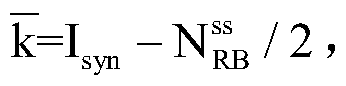 I
syn为同步信号块对应的中心PRB索引,
I
syn为同步信号块对应的中心PRB索引,
 为公共搜索空间的频域所占用的带宽,
 为下行带宽。
举例来说,图4为公共搜索空间资源映射的示意图二,如图4所示,假设网络中共有4个公共搜索空间s(0),...,s(3),令I
syn为同步信号块对应的中心PRB索引,则s(0),...,s(3)的公共搜索空间的候选资源的频域资源起始PRB可以根据公式(7)-公式(10)进行计算:


另外,采用公式(6)计算公共搜索空间的候选资源的频域资源起始PRB时,由于可以将公共搜索空间配置在公共信号资源带宽内,这样,终端即可在该公共信号资源带宽内检测同步信号、广播信号或公共搜索空间,由此可以降低终端的信令开销。
当然,网络设备还可以通过其他方式确定公共搜索空间的候选资源,例如假设网络中共有4个公共搜索空间s(0),...,s(3),令I
syn为同步信号块对应的中心PRB索引,则s(0),...,s(3)的公共搜索空间的候选资源的频域资源起始PRB可以根据公式(11)-公式(14)进行计算:


其中,

可选地,终端接收网络设备发送的配置信息,包括终端接收网络设备发送的主系统信息块(Master System Information Block;MIB)消息,该MIB消息包括配置信息。
具体地,网络设备在确定出用于指示公共搜索空间的多个候选资源中的资源的配置信息之后,可以将配置信息携带在MIB消息中发送给终端。在实际应用中,网络设备可以通过MIB的css-Config字段指示配置信息,在具体的实现过程中,可以通过如下方式实现:

其中,css-Resource的取值为“00”指示所配置的公共搜索空间的候选资源为s(0),css-Resource的取值为“01”指示所配置的公共搜索空间资源子集为s(1)等。
另外,网络设备通过MIB消息指示配置信息时,将通过MIB中长度为log
2M的css-Config字段指示配置信息,其中,M为公共搜索空间候选资源的个数。
步骤202、网络设备在配置信息所指示的资源上发送公共控制信息。
在本实施例中,网络设备在确定出公共搜索空间的多个候选资源后,将从多个候选资源中选择一个或多个资源,并通过MIB指示给终端。另外,网络设备将在配置信息所指示的资源上发送公共控制信息。
可选地,公共控制信息包括SIB、RAR、寻呼消息paging中至少一种的配置信息。
可选地,配置信息包括候选资源的索引。
可选地,配置信息用于指示资源的频域资源起始值。其中,频域资源起始值又为频域资源起始位置或频域资源偏置值,例如可以为最低PRB索引。
可选地,公共控制信息包括DCI,该DCI用于指示传输单元格式和/或用于指示传输单元内物理下行控制区域的符号数。
具体地,传输单元为时域结构,可以是子帧、时隙、微时隙、聚合时隙或聚合微时隙等,传输单元格式为传输单元中下行控制区域、下行数据区域、上行数据区域和上行控制区域的组成情况。传输单元格式可以包括以下一种或多种:(1)全下行:包括下行控制区域和下行数据区域,或者全部为下行数据区域;(2)下行为主:包括下行控制区域、下行数据区域,和上行控制区域,或者包括下行数据区域和上行控制区域;(3)上行为主:包括下行控制区域、上行数据区域,和上行控制区域,或者包括下行控制区域和上行数据区域;(4)全上行:包括上行数据区域和上行控制区域,或者全部为上行数据区域,或者全部为上行控制区域。
另外,DCI用于指示传输单元格式和/或用于指示传输单元内物理下行控制区域的符号数包括如下几种情况:(1)DCI仅用于指示传输单元格式;(2)DCI仅用于指示传输单元内物理下行控制区域的符号数;(3)DCI用于指示传输单元格式和用于指示传输单元内物理下行控制区域的符号数。
可选地,公共控制信息包括DCI,该DCI包括配置信息,该配置信息用于指示系统带宽。
具体地,网络设备可以根据网络中的数据业务的多少确定系统带宽,如当网络中 的数据业务较少时,采用较小的系统带宽;当网络中的数据业务较多时,采用较大的系统带宽。网络设备在确定出系统带宽之后,将用于指示系统带宽的配置信息携带在DCI中发送给终端,终端在接收到网络设备指示的系统带宽后,将采用该系统带宽进行通信,如在该系统带宽上接收数据和控制信息等。由于网络设备可以根据网络中的数据业务的多少确定系统带宽,由此可以提高系统带宽确定的灵活性。
本申请实施例提供的通信方法,终端通过接收网络设备发送的配置信息,并在该配置信息所指示的资源上接收公共控制信息,其中,配置信息用于指示公共搜索空间的多个候选资源中的资源,公共搜索空间的候选资源是根据小区标识、下行带宽、同步信道的频域资源位置、广播信道的频域资源位置中的一个或更多个确定的。由于网络设备根据小区标识、下行带宽、同步信道的频域资源位置、广播信道的频域资源位置中的一个或多个确定出公共搜索空间的候选资源,并使终端在配置信息所指示的资源上接收公共控制信息,由此可以使得公共搜索空间的确定方式更加灵活。
在图1所示的系统架构的基础上,在现有技术中,物理控制格式指示信道(Physical Control Format Indicator Channel;PCFICH)携带的信息为控制格式指示(Control Format Indicator;CFI),且CFI的取值范围为1~3(即CFI=1、2或3;用2比特表示,CFI=4为预留,不使用)。对于下行系统带宽
 控制区域所占的正交频分复用(Orthogonal Frequency Diversity Multiplexing;OFDM)符号数为1(CFI=1)或2(CFI=2)或3(CFI=3),即等于CFI;对于下行系统带宽
 控制区域所占的OFDM符号数为2(CFI=1)或3(CFI=2)或4(CFI=3),即等于CFI+1。PCFICH的物理层处理过程如下:2比特的CFI会先经过码率为1/16的信道编码,得到一个32比特的码字;接着,会使用小区和子帧特定的扰码对32比特的码字进行加扰,以随机化小区间干扰;然后,对加扰后的32个加扰比特进行正交相移键控(Quadrature Phase Shift Keying;QPSK)调制,得到16个调制符号,再把16个调制符号进行层匹配和预编码,映射到对应的资源元素(Resource Element;RE)中。由于只有PCFICH被正确解码,终端才能获取控制区域的大小,因此网络设备总是将PCFICH放在每个子帧的第一个OFDM符号中发送。另外,PCFICH的16个调制符号被分为4组,每组占一个资源元素组(Resource Element Block;REG),每个REG包含4个可用于传输的RE,这4个REG平均分布在整个下行系统带宽中,以获得频率分集增益。
每个REG包含的信息用公式(15)表示:
z
(p)(i)=y
(p)(4i),y
(p)(4i+1),y
(p)(4i+2),y
(p)(4i+3) (15)
其中,i表示每个REG的索引,其取值范围为0~3。每个REG的起始RE所在的位置通过公式(16)计算:

其中,z
(p)(0)-z
(p)(3)被映射的资源元素组可以根据公式(16)-公式(19)计算:


其中,
 为小区标识,
 为系统带宽,
 为一个资源块内的载波数。
由上述内容可知,在现有技术中,对于给定小区给定下行系统带宽,PCFICH会映射在固定的资源上,使得配置PCFICH资源的灵活性不高。
本申请实施例考虑到这些情况,提出一种通信方法,终端通过接收网络设备发送的配置信息,该配置信息用于指示物理信道的频域资源起始值,该物理信道用于指示传输单元格式和/或用于指示传输单元内物理下行控制区域的符号数,终端在频域资源起始值指示的资源上接收物理信道。由于网络设备将用于指示物理信道的频域资源起始值的配置信息发送给终端,终端在该频域资源起始值指示的资源上接收物理信道,由此可以提高物理信道配置的灵活性。
图5为本申请通信方法实施例二的信令流程图。在上述图1所示系统架构的基础上,如图5所示,本实施例的方法可以包括:
步骤501、终端接收网络设备发送的配置信息,该配置信息用于指示物理信道的频域资源起始值,该物理信道用于指示传输单元格式和/或用于指示传输单元内物理下行控制区域的符号数。
在本实施例中,物理信道可以为不同于物理下行控制信道(Physical Downlink Control Channel;PDCCH)的一个新的物理下行信道,也可以为DCI,对于物理信道的具体形式,本实施例在此不作限制。频域资源起始值又称为频域资源偏置值或频域资源起始位置,例如可以为最低PRB索引等。另外,传输单元为时域结构,可以是子帧、时隙、微时隙、聚合时隙或聚合微时隙等。
下面,将详细介绍网络设备确定物理信道的频域资源起始值的具体过程。
图6为物理信道资源映射的示意图,如图6所示,当物理信道承载的信息比特数较少(例如2比特)时,网络设备向终端发送用于指示物理信道的频域资源起始值,另外,将由2比特时隙结构的指示信息经过处理获得的16个调制符号分为4组,即z(0),...,z(3),并均匀分布在控制资源子集所在频段内,若令
 则z(0),...,z(3)的频域资源起始值将分别根据公式(20)-公式(23)计算:


其中,N
offset为频域资源起始值。
可选地,终端接收网络设备发送的配置信息,包括:终端接收网络设备发送的广播信令或高层信令,该广播信令或高层信令包括配置信息。
具体地,广播信令例如可以为MIB消息,高层信令例如可以为SIB消息或用户特定RRC消息。由于网络设备通过广播信令或高层信令向终端发送配置信息,这样,可 以使一部分用户可以检测到该配置信息。
可选地,物理信道映射的频域资源是根据小区标识、控制资源子集所对应的带宽中的一个或更多确定的。具体地,小区标识可以为通过半静态方式或者通过静态方式配置给小区的标识,例如可以为PCI。另外,控制资源子集为预定义带宽的子带带宽。
可选地,物理信道映射的时域资源是传输单元的第一个符号。
可选地,控制资源子集用于传输公共下行控制信息,该公共下行控制信息包括系统消息块SIB、随机接入响应RAR、寻呼消息中至少一种的配置信息。
可选地,控制资源子集用于传输用户组特定下行控制信息和/或用户特定下行控制信息。具体地,将所述物理信道映射在公共搜索空间/用户组特定搜索空间所在控制资源子集内,可以使得用户在检测公共搜索空间的同时,可以同时检测物理信道。其中,公共搜索空间用于传输公共下行控制信息,小区内所有用户都需要接收该公共下行控制信息,用户组特定搜索空间用于传输用户组特定下行控制信息,小区内一个或多个用户需要接收该用户组特定下行控制信息。
另外,控制资源子集可以仅用于传输用户组特定下行控制信息,控制资源子集也可以仅用于传输用户特定下行控制信息,控制资源子集还可以用于传输用户组特定下行控制信息和用户特定下行控制信息。
可选地,频域资源起始值为控制资源子集对应的最低PRB索引。
可选地,物理信道映射在资源上,包括:对物理信道对应的信息比特进行信道编码,对编码后比特进行加扰,所述加扰序列由小区标识、传输单元索引确定,对加扰后比特进行调制,将调制符号映射在所述资源上。
具体地,物理信道的物理层处理过程包括:将物理信道对应的信息比特,例如2比特时隙传输单元的指示信息先经过码率为1/16的信道进行编码,得到一个32比特的码字,在使用由小区标识和传输单元索引确定出的加扰序列对32比特的码字进行加扰,再对32比特的加扰后码字进行QPSK调制,得到16个调制符号,16个调制符号映射在控制资源子集所在频段内。
可选地,资源在下行控制信道内预定义的K个下行CCE对应的资源中。
可选地,K个CCE为下行控制信道的前K个CCE。
具体地,为保证物理信道的有无对用户盲检控制信道的影响最小,所述调制符号还可以尽可能地集中映射在所述控制资源子集中的若干预定义CCE中。例如,假设一个CCE占用4个REG,若CCE单符号映射,则所述16个调制符号映射在所述控制资源子集内预定义的1个CCE中的2个或4个REG上,若CCE跨符号(2符号)映射,则所述16个调制符号映射在所述控制资源子集中预定义的1个CCE的2个REG上,或者分别映射在预定义2个CCE中的前2个REG上。需要进行说明的是,终端除非被指示某给定传输单元中不包含所述物理信道,一般所述物理信道对应的CCE中不包含下行控制信息。
可选地,物理信道对应的信息为下行控制信息,下行控制信息由下行控制信道承载,下行控制信息位于下行控制信道公共搜索空间和/或用户组搜索空间中。
可选地,物理信道对应的信息由预定义数量的L个CCE承载,该L个CCE的最低CCE的索引为预定义,候选集数量为1。
可选地,最低CCE的索引为公共搜索空间的第一个CCE的索引。
可选地,CCE的索引为用户组搜索空间的第一个CCE的索引。
具体地,当所述物理信道承载的信息比特数较多(例如25比特)时,物理信道实质上是一个公共DCI或用户组特定DCI。此时,为降低用户盲检复杂度,物理信道可以映射在预定义的连续若干CCE中,这里“预定义”包括CCE个数和CCE索引均是预定义的。也即,承载信息的下行控制信息使用的起始CCE为预定义,聚合等级L为预定义,候选集数量为1。例如,所述25比特信息映射在所述控制资源子集以第1个CCE为起始的4个CCE中(假设聚合等级为4,循环冗余校验(Cyclic Redundancy Check)位为24比特,并采用QPSK调制)。
步骤502、所述网络设备在所述频域资源起始值指示的资源上发送所述物理信道。
在本实施例中,网络设备在将用于指示物理信道的频域资源起始值的配置信息发送给终端之后,将在频域资源起始值指示的资源上发送物理信道。终端在接收到网络设备发送的配置信息之后,将在频域资源起始值指示的资源上接收物理信道。
另外,本实施例中是将物理信道配置在一个控制资源子集所在频段内。由此,相比于现有的PCFICH信道,本实施例中的物理信道的资源只在控制资源子集所在频段中展开,而且将半静态配置频域资源起始值,该半静态频域资源起始值可以与所述控制资源子集所在频段的最低PRB索引相同,也可以是一个独立配置的值。
本申请实施例提供的通信方法,终端通过接收网络设备发送的配置信息,该配置信息用于指示物理信道的频域资源起始值,该物理信道用于指示传输单元格式和/或用于指示传输单元内物理下行控制区域的符号数,终端在频域资源起始值指示的资源上接收物理信道。由于网络设备将用于指示物理信道的频域资源起始值的配置信息发送给终端,终端在该频域资源起始值指示的资源上接收物理信道,由此可以提高物理信道配置的灵活性。
图7为本申请通信方法实施例三的信令流程图。在上述图1所示系统架构的基础上,如图7所示,本实施例的方法可以包括:
步骤701、终端接收网络设备发送的DCI,DCI包括配置信息,配置信息用于指示系统带宽。
在本实施例中,网络设备可以根据数据业务的多少确定系统带宽,例如,当网络中的数据业务较少时,采用较小的系统带宽;当网络中的数据业务较多时,采用较大的系统带宽。网络设备可以通过将配置信息携带在DCI中发送给终端,以向终端指示网络设备确定出的系统带宽。另外,网络设备在确定出系统带宽之后,将在下一个时隙在确定出的新的带宽上与终端进行通信,如在新的带宽上发送数据和控制信息等。
另外,系统带宽可以预定义为几种不同的大小。举例来说,系统带宽可以预定义为如表1中所示的8种大小,此时,DCI可用3比特指示所选系统带宽。
表1

可选地,图8为DCI的结构示意图,如图8所示,有限粒度的大小例如可以为30位、60位或90位,其中,头部的值若为00,则表示下行链路分配,若为01,则表示上行授权,若为10,则表示重新配置等等,信息则可以表示资源分配,调制与编码策略(Modulation and Coding Scheme;MCS),混合自动重传请求(Hybrid Automatic Repeat reQuest;HARQ)参数等。
为了降低DCI的盲检次数,NR会支持几种DCI payload大小。为了保持DCI payload大小相同,需要一些冗余比特,此时,DCI可以通过其他公共DCI的冗余比特承载。
可选地,UE在处于RRC空闲状态时,需要通过公共搜索空间的检索完成小区附着。然而,所述公共搜索空间的配置依赖于灵活下行带宽。因此,需要通过MIB指示灵活下行带宽。根据3GPP讨论,现有如下两种可能:
第一种,MIB中只包括第一系统带宽的配置信息,在实际应用中,可以通过如下方式实现:

第二种,MIB中包括第一系统带宽的配置信息和第二系统带宽的配置信息,其中,第一系统带宽和第二系统带宽可以用于不同物理信道或物理信号的资源确定。在实际应用中,可以通过如下方式实现:

可选地,该方法还包括发送能力信息,该能力信息用于指示终端支持系统带宽。
具体地,终端可以通过初始接入前导(消息1)或消息3上报终端的能力信息,网络设备将根据终端上报的能力信息决定是否根据数据业务多少灵活配置带宽,以确定系统带宽的大小。其中,该能力信息用于指示终端支持系统带宽,该能力信息包括终端能支持的带宽、系统参数集中的一种或多种,该系统参数集包括子载波间隔大小、循环前缀长度、传输时间间隔长度、符号长度和符号数等参数中的一种或多种。
步骤702、终端采用系统带宽进行通信。
在本实施例中,终端接收到网络设备发送的用于指示系统带宽的配置信息之后,将根据网络设备指示的系统带宽进行通信。
本申请实施例提供的通信方法,终端通过接收网络设备发送的DCI,该DCI包括配置信息,配置信息用于指示系统带宽,终端采用系统带宽进行通信,由此可以提高 系统带宽确定的灵活性。
图9为本申请通信装置实施例一的结构示意图,该装置可以位于终端,参见图9,该装置包括:第一接收模块901和第二接收模块902,其中:
第一接收模块901用于接收网络设备发送的配置信息,所述配置信息用于指示公共搜索空间的多个候选资源中的资源,所述公共搜索空间的候选资源是根据小区标识、下行带宽、同步信道的频域资源位置、广播信道的频域资源位置中的一个或更多个确定的;
第二接收模块902用于在所述配置信息所指示的资源上接收公共控制信息。
本实施例中,第一接收模块901通过接收网络设备发送的配置信息,第二接收模块902在该配置信息所指示的资源上接收公共控制信息,其中,配置信息用于指示公共搜索空间的多个候选资源中的资源,公共搜索空间的候选资源是根据小区标识、下行带宽、同步信道的频域资源位置、广播信道的频域资源位置中的一个或更多个确定的。由于网络设备根据小区标识、下行带宽、同步信道的频域资源位置、广播信道的频域资源位置中的一个或多个确定出公共搜索空间的候选资源,并使终端在配置信息所指示的资源上接收公共控制信息,由此可以使得公共搜索空间的确定方式更加灵活。
进一步地,所述第一接收模块901用于接收所述网络设备发送的主系统信息块MIB消息,所述MIB消息包括所述配置信息。
可选地,所述公共控制信息包括系统消息块SIB、随机接入响应RAR、寻呼消息中至少一种的配置信息。
可选地,所述配置信息包括候选资源的索引。
可选地,所述配置信息用于指示所述资源的频域资源起始值。
可选地,所述公共控制信息包括下行控制信息DCI,所述DCI用于指示传输单元格式和/或用于指示传输单元内物理下行控制区域的符号数。
可选地,所述公共控制信息包括下行控制信息DCI,所述DCI包括配置信息,所述配置信息用于指示系统带宽。
可选地,如图9所示,所述装置还包括:触发模块903,其中:
触发模块903用于触发所述终端采用所述系统带宽进行通信。
上述装置可用于执行上述对应方法实施例提供的方法,具体实现方式和技术效果类似,这里不再赘述。
需要说明的是,应理解以上通信装置的各个模块的划分仅仅是一种逻辑功能的划分,实际实现时可以全部或部分集成到一个物理实体上,也可以物理上分开。且这些模块可以全部以软件通过处理元件调用的形式实现;也可以全部以硬件的形式实现;还可以部分模块通过软件通过处理元件调用的形式实现,部分模块通过硬件的形式实现。例如,接收模块可以为单独设立的处理元件,也可以集成在终端的某一个芯片中实现,此外,也可以以程序的形式存储于终端的存储器中,由终端的某一个处理元件调用并执行该接收模块的功能。其它模块的实现与之类似。此外这些模块全部或部分可以集成在一起,也可以独立实现。这里所述的处理元件可以是一种集成电路,具有信号的处理能力。在实现过程中,上述方法的各步骤或以上各个模块可以通过处理器元件中的硬件的集成逻辑电路或者软件形式的指令完成。此外,以上接收模块是一种控制接收的模块,可以通过终端的接收装置,例如天线和射频装置接收基站发送的信 息。
以上这些模块可以是被配置成实施以上方法的一个或多个集成电路,例如:一个或多个特定集成电路(Application Specific Integrated Circuit,ASIC),或,一个或多个微处理器(digital singnal processor,DSP),或,一个或者多个现场可编程门阵列(Field Programmable Gate Array,FPGA)等。再如,当以上某个模块通过处理元件调度程序的形式实现时,该处理元件可以是通用处理器,例如中央处理器(Central Processing Unit,CPU)或其它可以调用程序的处理器。再如,这些模块可以集成在一起,以片上系统(system-on-a-chip,SOC)的形式实现。
图10为本申请通信装置实施例二的结构示意图,该装置可以位于网络设备,参见图10,该装置包括:第一发送模块1001和第二发送模块,其中:
第一发送模块1001用于发送配置信息,所述配置信息用于指示公共搜索空间的多个候选资源中的资源,所述公共搜索空间的候选资源是根据小区标识、下行带宽、同步信道的频域资源位置、广播信道的频域资源位置中的一个或更多个确定的;
第二发送模块1002用于在所述配置信息所指示的资源上发送公共控制信息。
本实施例中,第一发送模块1001通过发送配置信息,该配置信息用于指示公共搜索空间的多个候选资源中的资源,公共搜索空间的候选资源是根据小区标识、下行带宽、同步信道的频域资源位置、广播信道的频域资源位置中的一个或更多个确定的,第二发送模块1002在配置信息所指示的资源上发送公共控制信息。由于网络设备根据小区标识、下行带宽、同步信道的频域资源位置、广播信道的频域资源位置中的一个或多个确定出公共搜索空间的候选资源,并在配置信息所指示的资源上发送公共控制信息,由此可以使得公共搜索空间的确定方式更加灵活。
可选地,所述第一发送模块1001用于发送主系统信息块MIB消息,所述MIB消息包括所述配置信息。
可选地,所述公共控制信息包括系统消息块SIB、随机接入响应RAR、寻呼消息中至少一种的配置信息。
可选地,所述配置信息包括候选资源的索引。
可选地,所述配置信息用于指示所述资源的频域资源起始值。
可选地,所述公共控制信息包括下行控制信息DCI,所述DCI用于指示传输单元格式和/或用于指示传输单元内物理下行控制区域的符号数。
可选地,所述公共控制信息包括下行控制信息DCI,所述DCI包括配置信息,所述配置信息用于指示系统带宽。
上述装置可用于执行上述对应方法实施例提供的方法,具体实现方式和技术效果类似,这里不再赘述。
需要说明的是,应理解以上通信装置的各个模块的划分仅仅是一种逻辑功能的划分,实际实现时可以全部或部分集成到一个物理实体上,也可以物理上分开。且这些模块可以全部以软件通过处理元件调用的形式实现;也可以全部以硬件的形式实现;还可以部分模块通过软件通过处理元件调用的形式实现,部分模块通过硬件的形式实现。例如,第一发送模块可以为单独设立的处理元件,也可以集成在基站的某一个芯片中实现,此外,也可以以程序的形式存储于基站的存储器中,由基站的某一个处理元件调用并执行该第一发送模块的功能。其它模块的实现与之类似。此外这些模块全 部或部分可以集成在一起,也可以独立实现。这里所述的处理元件可以是一种集成电路,具有信号的处理能力。在实现过程中,上述方法的各步骤或以上各个模块可以通过处理器元件中的硬件的集成逻辑电路或者软件形式的指令完成。此外,以上第一发送模块是一种控制发送的模块,可以通过基站的发送装置,例如天线和射频装置向终端发送信息,第二发送模块与之类似。
以上这些模块可以是被配置成实施以上方法的一个或多个集成电路,例如:一个或多个特定集成电路(Application Specific Integrated Circuit,ASIC),或,一个或多个微处理器(digital singnal processor,DSP),或,一个或者多个现场可编程门阵列(Field Programmable Gate Array,FPGA)等。再如,当以上某个模块通过处理元件调度程序的形式实现时,该处理元件可以是通用处理器,例如中央处理器(Central Processing Unit,CPU)或其它可以调用程序的处理器。再如,这些模块可以集成在一起,以片上系统(system-on-a-chip,SOC)的形式实现。
图11为本申请通信装置实施例三的结构示意图,该装置可以位于终端,参见图11,该装置包括:第一接收模块1101和第二接收模块1102,其中:
第一接收模块1101用于接收网络设备发送的配置信息,该配置信息用于指示物理信道的频域资源起始值,物理信道用于指示传输单元格式和/或用于指示传输单元内物理下行控制区域的符号数;
第二接收模块1102用于在频域资源起始值指示的资源上接收物理信道。
在本实施例中,第一接收模块1101通过接收网络设备发送的配置信息,该配置信息用于指示物理信道的频域资源起始值,该物理信道用于指示传输单元格式和/或用于指示传输单元内物理下行控制区域的符号数,第二接收模块1102在频域资源起始值指示的资源上接收物理信道。由于网络设备将用于指示物理信道的频域资源起始值的配置信息发送给终端,终端在该频域资源起始值指示的资源上接收物理信道,由此可以提高物理信道配置的灵活性。
可选地,终端接收网络设备发送的配置信息,包括:接收网络设备发送的广播信令或高层信令,该广播信令或高层信令包括配置信息。
可选地,物理信道映射的频域资源是根据小区标识、控制资源子集所对应的带宽中的一个或更多确定的。
可选地,控制资源子集用于传输公共下行控制信息,该公共下行控制信息包括系统消息块SIB、随机接入响应RAR、寻呼消息中至少一种的配置信息。
可选地,控制资源子集用于传输用户组特定下行控制信息和/或用户特定下行控制信息。
可选地,频域资源起始值为控制资源子集对应的最低PRB索引。
可选地,物理信道映射在资源上,包括:对物理信道对应的信息比特进行信道编码,对编码后比特进行加扰,所述加扰序列由小区标识、传输单元索引确定,对加扰后比特进行调制,将调制符号映射在所述资源上。
可选地,资源为下行控制信道内预定义的K个下行CCE对应的资源。其中,所述K个CCE为所述下行控制信道的前K个CCE。
可选地,物理信道对应的信息为下行控制信息,下行控制信息由下行控制信道承载,下行控制信息位于下行控制信道公共搜索空间和/或用户组搜索空间中。
可选地,物理信道对应的信息由预定义数量的L个CCE承载,该L个CCE的最低CCE的索引为预定义。也即,承载信息的下行控制信息使用的起始CCE为预定义,聚合等级L为预定义,候选集数量为1。
可选地,最低CCE的索引为公共搜索空间的第一个CCE的索引。
可选地,CCE的索引为用户组搜索空间的第一个CCE的索引。
上述装置可用于执行上述对应方法实施例提供的方法,具体实现方式和技术效果类似,这里不再赘述。
需要说明的是,应理解以上通信装置的各个模块的划分仅仅是一种逻辑功能的划分,实际实现时可以全部或部分集成到一个物理实体上,也可以物理上分开。且这些模块可以全部以软件通过处理元件调用的形式实现;也可以全部以硬件的形式实现;还可以部分模块通过软件通过处理元件调用的形式实现,部分模块通过硬件的形式实现。例如,第一接收模块可以为单独设立的处理元件,也可以集成在终端的某一个芯片中实现,此外,也可以以程序的形式存储于终端的存储器中,由终端的某一个处理元件调用并执行该第一接收模块的功能。其它模块的实现与之类似。此外这些模块全部或部分可以集成在一起,也可以独立实现。这里所述的处理元件可以是一种集成电路,具有信号的处理能力。在实现过程中,上述方法的各步骤或以上各个模块可以通过处理器元件中的硬件的集成逻辑电路或者软件形式的指令完成。此外,以上接收模块是一种控制接收的模块,可以通过终端的接收装置,例如天线和射频装置接收基站发送的信息。
以上这些模块可以是被配置成实施以上方法的一个或多个集成电路,例如:一个或多个特定集成电路(Application Specific Integrated Circuit,ASIC),或,一个或多个微处理器(digital singnal processor,DSP),或,一个或者多个现场可编程门阵列(Field Programmable Gate Array,FPGA)等。再如,当以上某个模块通过处理元件调度程序的形式实现时,该处理元件可以是通用处理器,例如中央处理器(Central Processing Unit,CPU)或其它可以调用程序的处理器。再如,这些模块可以集成在一起,以片上系统(system-on-a-chip,SOC)的形式实现。
图12为本申请通信装置实施例四的结构示意图,该装置可以位于网络设备,参见图12,该装置包括:第一发送模块1201和第二发送模块1202,其中:
第一发送模块1201用于发送配置信息,该配置信息用于指示物理信道的频域资源起始值,物理信道用于指示传输单元格式和/或用于指示传输单元内物理下行控制区域的符号数;
第二发送模块1202用于在频域资源起始值指示的资源上发送物理信道。
在本实施例中,第一发送模块1201通过发送配置信息,该配置信息用于指示物理信道的频域资源起始值,物理信道用于指示传输单元格式和/或用于指示传输单元内物理下行控制区域的符号数,第二发送模块1202在频域资源起始值指示的资源上发送物理信道。由于网络设备向终端发送用于指示物理信道的频域资源起始值的配置信息,并在频域资源起始值指示的资源上发送物理信道,由此可以提高物理信道配置的灵活性。
可选地,网络设备发送配置信息,包括:网络设备发送广播信令或高层信令,该广播信令或高层信令包括配置信息。
可选地,物理信道映射的频域资源是根据小区标识、控制资源子集所对应的带宽中的一个或更多确定的。
可选地,控制资源子集用于传输公共下行控制信息,该公共下行控制信息包括系统消息块SIB、随机接入响应RAR、寻呼消息中至少一种的配置信息。
可选地,控制资源子集用于传输用户组特定下行控制信息和/或用户特定下行控制信息。
可选地,频域资源起始值为控制资源子集对应的最低PRB索引。
可选地,物理信道映射在资源上,包括:对物理信道对应的信息比特进行信道编码,对编码后比特进行加扰,所述加扰序列由小区标识、传输单元索引确定,对加扰后比特进行调制,将调制符号映射在所述资源上。
可选地,资源为下行控制信道内预定义的K个下行CCE对应的资源。其中,所述K个CCE为所述下行控制信道的前K个CCE。
可选地,物理信道对应的信息为下行控制信息,下行控制信息由下行控制信道承载,下行控制信息位于下行控制信道公共搜索空间和/或用户组搜索空间中。
可选地,物理信道对应的信息由预定义数量的L个CCE承载,该L个CCE的最低CCE的索引为预定义。也即,承载信息的下行控制信息使用的起始CCE为预定义,聚合等级L为预定义,候选集数量为1。
可选地,最低CCE的索引为公共搜索空间的第一个CCE的索引。
可选地,CCE的索引为用户组搜索空间的第一个CCE的索引。
上述装置可用于执行上述对应方法实施例提供的方法,具体实现方式和技术效果类似,这里不再赘述。
需要说明的是,应理解以上通信装置的各个模块的划分仅仅是一种逻辑功能的划分,实际实现时可以全部或部分集成到一个物理实体上,也可以物理上分开。且这些模块可以全部以软件通过处理元件调用的形式实现;也可以全部以硬件的形式实现;还可以部分模块通过软件通过处理元件调用的形式实现,部分模块通过硬件的形式实现。例如,第一发送模块可以为单独设立的处理元件,也可以集成在基站的某一个芯片中实现,此外,也可以以程序的形式存储于基站的存储器中,由基站的某一个处理元件调用并执行该第一发送模块的功能。其它模块的实现与之类似。此外这些模块全部或部分可以集成在一起,也可以独立实现。这里所述的处理元件可以是一种集成电路,具有信号的处理能力。在实现过程中,上述方法的各步骤或以上各个模块可以通过处理器元件中的硬件的集成逻辑电路或者软件形式的指令完成。此外,以上第一发送模块是一种控制发送的模块,可以通过基站的发送装置,例如天线和射频装置向终端发送信息,第二发送模块与之类似。
以上这些模块可以是被配置成实施以上方法的一个或多个集成电路,例如:一个或多个特定集成电路(Application Specific Integrated Circuit,ASIC),或,一个或多个微处理器(digital singnal processor,DSP),或,一个或者多个现场可编程门阵列(Field Programmable Gate Array,FPGA)等。再如,当以上某个模块通过处理元件调度程序的形式实现时,该处理元件可以是通用处理器,例如中央处理器(Central Processing Unit,CPU)或其它可以调用程序的处理器。再如,这些模块可以集成在一起,以片上系统(system-on-a-chip,SOC)的形式实现。
图13为本申请通信装置实施例五的结构示意图,该装置可以位于终端,参见图13,该装置包括:接收模块1301和触发模块1302,其中:
接收模块1301,用于接收网络设备发送的DCI,该DCI包括配置信息,配置信息用于指示系统带宽;
触发模块1302,用于触发终端采用系统带宽进行通信。
在本实施例中,接收模块1301通过接收网络设备发送的DCI,该DCI包括配置信息,配置信息用于指示系统带宽,触发模块1302采用系统带宽进行通信。由于网络设备向终端指示可用的系统带宽,终端将根据网络设备指示的系统带宽进行通信,由此可以提高确定系统带宽的灵活性。
可选地,该方法还包括发送能力信息,该能力信息用于指示终端支持系统带宽。
上述装置可用于执行上述对应方法实施例提供的方法,具体实现方式和技术效果类似,这里不再赘述。
需要说明的是,应理解以上通信装置的各个模块的划分仅仅是一种逻辑功能的划分,实际实现时可以全部或部分集成到一个物理实体上,也可以物理上分开。且这些模块可以全部以软件通过处理元件调用的形式实现;也可以全部以硬件的形式实现;还可以部分模块通过软件通过处理元件调用的形式实现,部分模块通过硬件的形式实现。例如,触发模块可以为单独设立的处理元件,也可以集成在终端的某一个芯片中实现,此外,也可以以程序的形式存储于终端的存储器中,由终端的某一个处理元件调用并执行该触发模块的功能。其它模块的实现与之类似。此外这些模块全部或部分可以集成在一起,也可以独立实现。这里所述的处理元件可以是一种集成电路,具有信号的处理能力。在实现过程中,上述方法的各步骤或以上各个模块可以通过处理器元件中的硬件的集成逻辑电路或者软件形式的指令完成。此外,以上接收模块是一种控制接收的模块,可以通过终端的接收装置,例如天线和射频装置接收基站发送的信息。
以上这些模块可以是被配置成实施以上方法的一个或多个集成电路,例如:一个或多个特定集成电路(Application Specific Integrated Circuit,ASIC),或,一个或多个微处理器(digital singnal processor,DSP),或,一个或者多个现场可编程门阵列(Field Programmable Gate Array,FPGA)等。再如,当以上某个模块通过处理元件调度程序的形式实现时,该处理元件可以是通用处理器,例如中央处理器(Central Processing Unit,CPU)或其它可以调用程序的处理器。再如,这些模块可以集成在一起,以片上系统(system-on-a-chip,SOC)的形式实现。
图14为本申请通信装置实施例六的结构示意图,该装置可以位于网络设备,参见图14,该装置包括:发送模块1401和触发模块1402,其中:
发送模块1401,用于向终端发送DCI,DCI包括配置信息,配置信息用于指示系统带宽;
触发模块1402,用于触发基站采用系统带宽与终端通信。
在本实施例中,网络设备通过向终端发送DCI,DCI包括配置信息,配置信息用于指示系统带宽;网络设备采用系统带宽与终端通信。由于网络设备向终端指示可用的系统带宽,并采用该系统带宽与终端进行通信,由此可以提高确定系统带宽的灵活性。
可选地,该方法还包括发送能力信息,该能力信息用于指示终端支持系统带宽。
上述装置可用于执行上述方法实施例提供的方法,具体实现方式和技术效果类似,这里不再赘述。
需要说明的是,应理解以上通信装置的各个模块的划分仅仅是一种逻辑功能的划分,实际实现时可以全部或部分集成到一个物理实体上,也可以物理上分开。且这些模块可以全部以软件通过处理元件调用的形式实现;也可以全部以硬件的形式实现;还可以部分模块通过软件通过处理元件调用的形式实现,部分模块通过硬件的形式实现。例如,发送模块可以为单独设立的处理元件,也可以集成在上述装置的某一个芯片中实现,此外,也可以以程序的形式存储于上述装置的存储器中,由上述装置的某一个处理元件调用并执行以上各个模块的功能。其它模块的实现与之类似。此外这些模块全部或部分可以集成在一起,也可以独立实现。这里所述的处理元件可以是一种集成电路,具有信号的处理能力。在实现过程中,上述方法的各步骤或以上各个模块可以通过处理器元件中的硬件的集成逻辑电路或者软件形式的指令完成。此外,以上发送模块是一种控制发送的模块,可以通过基站的发送装置,例如天线和射频装置向终端发送信息。
以上这些模块可以是被配置成实施以上方法的一个或多个集成电路,例如:一个或多个特定集成电路(Application Specific Integrated Circuit,ASIC),或,一个或多个微处理器(digital singnal processor,DSP),或,一个或者多个现场可编程门阵列(Field Programmable Gate Array,FPGA)等。再如,当以上某个模块通过处理元件调度程序的形式实现时,该处理元件可以是通用处理器,例如中央处理器(Central Processing Unit,CPU)或其它可以调用程序的处理器。再如,这些模块可以集成在一起,以片上系统(system-on-a-chip,SOC)的形式实现。
图15为本申请实施例提供的一种终端的结构示意图,参见图15,该终端包括:处理器110、存储器120、收发装置130。其中,收发装置130可以与天线连接。在下行方向上,收发装置130通过天线接收网络设备发送的信息,并将信息发送给处理器110进行处理。在上行方向上,处理器110对终端的数据进行处理,并通过收发装置130发送给网络设备。
该存储器120用于存储实现以上方法实施例,或者图9、图11或图13所示实施例各个模块的程序,处理器110调用该程序,执行以上方法实施例的操作,以实现图9、图11或图13所示的各个模块。
或者,以上各个单元的部分或全部也可以通过集成电路的形式内嵌于该终端的某一个芯片上来实现。且它们可以单独实现,也可以集成在一起。即以上这些单元可以被配置成实施以上方法的一个或多个集成电路,例如:一个或多个特定集成电路(Application Specific Integrated Circuit,ASIC),或,一个或多个微处理器(digital singnal processor,DSP),或,一个或者多个现场可编程门阵列(Field Programmable Gate Array,FPGA)等。
图16为本申请实施例提供的一种网络设备的结构示意图,参见图16,该网络设备包括:天线110、射频装置120、基带装置130。天线110与射频装置120连接。在上行方向上,射频装置120通过天线110接收终端发送的信息,将终端发送的信息发送给基带装置130进行处理。在下行方向上,基带装置130对终端的信息进行处理, 并发送给射频装置120,射频装置120对终端的信息进行处理后经过天线110发送给终端。
以上通信装置可以位于基带装置130,在一种实现中,以上各个单元通过处理元件调度程序的形式实现,例如基带装置130包括处理元件131和存储元件132,处理元件131调用存储元件132存储的程序,以执行以上方法实施例中的方法。此外,该基带装置130还可以包括接口133,用于与射频装置120交互信息,该接口例如为通用公共无线接口(common public radio interface,CPRI)。
在另一种实现中,以上这些单元可以是被配置成实施以上方法的一个或多个处理元件,这些处理元件设置于基带装置130上,这里的处理元件可以为集成电路,例如:一个或多个ASIC,或,一个或多个DSP,或,一个或者多个FPGA等。这些集成电路可以集成在一起,构成芯片。
例如,以上各个单元可以集成在一起,以片上系统(system-on-a-chip,SOC)的形式实现,例如,基带装置130包括SOC芯片,用于实现以上方法。该芯片内可以集成处理元件131和存储元件132,由处理元件131调用存储元件132的存储的程序的形式实现以上方法或以上各个单元的功能;或者,该芯片内可以集成至少一个集成电路,用于实现以上方法或以上各个单元的功能;或者,可以结合以上实现方式,部分单元的功能通过处理元件调用程序的形式实现,部分单元的功能通过集成电路的形式实现。
不管采用何种方式,总之,以上通信装置包括至少一个处理元件,存储元件和通信接口,其中至少一个处理元件用于执行以上方法实施例所提供的方法。处理元件可以以第一种方式:即执行存储元件存储的程序的方式执行以上方法实施例中的部分或全部步骤;也可以以第二种方式:即通过处理器元件中的硬件的集成逻辑电路结合指令的方式执行以上方法实施例中的部分或全部步骤;当然,也可以结合第一种方式和第二种方式执行以上方法实施例提供的方法。
这里的处理元件同以上描述,可以是通用处理器,例如中央处理器(Central Processing Unit,CPU),还可以是被配置成实施以上方法的一个或多个集成电路,例如:一个或多个特定集成电路(Application Specific Integrated Circuit,ASIC),或,一个或多个微处理器(digital singnal processor,DSP),或,一个或者多个现场可编程门阵列(Field Programmable Gate Array,FPGA)等。
存储元件可以是一个存储器,也可以是多个存储元件的统称。
Claims (30)
- 一种通信方法,其特征在于,包括:终端接收网络设备发送的配置信息,所述配置信息用于指示公共搜索空间的多个候选资源中的资源,所述公共搜索空间的候选资源是根据小区标识、下行带宽、同步信道的频域资源位置、广播信道的频域资源位置中的一个或更多个确定的;所述终端在所述配置信息所指示的资源上接收公共控制信息。
- 根据权利要求1所述的方法,其特征在于,所述终端接收网络设备发送的配置信息,包括:所述终端接收所述网络设备发送的主系统信息块MIB消息,所述MIB消息包括所述配置信息。
- 根据权利要求1或2所述的方法,其特征在于,所述公共控制信息包括系统消息块SIB、随机接入响应RAR、寻呼消息中至少一种的配置信息。
- 根据权利要求1-3任一项所述的方法,其特征在于,所述配置信息包括候选资源的索引。
- 根据权利要求1-4任一项所述的方法,其特征在于,所述配置信息用于指示所述资源的频域资源起始值。
- 根据权利要求1-5任一项所述的方法,其特征在于,所述公共控制信息包括下行控制信息DCI,所述DCI用于指示传输单元格式和/或用于指示传输单元内物理下行控制区域的符号数。
- 根据权利要求1-6任一项所述的方法,其特征在于,所述公共控制信息包括下行控制信息DCI,所述DCI包括配置信息,所述配置信息用于指示系统带宽。
- 根据权利要求7所述的方法,其特征在于,所述方法还包括:所述终端采用所述系统带宽进行通信。
- 一种通信方法,其特征在于,包括:网络设备发送配置信息,所述配置信息用于指示公共搜索空间的多个候选资源中的资源,所述公共搜索空间的候选资源是根据小区标识、下行带宽、同步信道的频域资源位置、广播信道的频域资源位置中的一个或更多个确定的;所述网络设备在所述配置信息所指示的资源上发送公共控制信息。
- 根据权利要求9所述的方法,其特征在于,所述网络设备发送配置信息,包括:所述网络设备发送主系统信息块MIB消息,所述MIB消息包括所述配置信息。
- 根据权利要求9或10所述的方法,其特征在于,所述公共控制信息包括系统消息块SIB、随机接入响应RAR、寻呼消息中至少一种的配置信息。
- 根据权利要求9-11任一项所述的方法,其特征在于,所述配置信息包括候选资源的索引。
- 根据权利要求9-12任一项所述的方法,其特征在于,所述配置信息用于指示所述资源的频域资源起始值。
- 根据权利要求9-13任一项所述的方法,其特征在于,所述公共控制信息包括下行控制信息DCI,所述DCI用于指示传输单元格式和/或用于指示传输单元内物理下 行控制区域的符号数。
- 根据权利要求9-14任一项所述的方法,其特征在于,所述公共控制信息包括下行控制信息DCI,所述DCI包括配置信息,所述配置信息用于指示系统带宽。
- 一种通信装置,位于终端,其特征在于,包括:第一接收模块,用于接收网络设备发送的配置信息,所述配置信息用于指示公共搜索空间的多个候选资源中的资源,所述公共搜索空间的候选资源是根据小区标识、下行带宽、同步信道的频域资源位置、广播信道的频域资源位置中的一个或更多个确定的;第二接收模块,用于在所述配置信息所指示的资源上接收公共控制信息。
- 根据权利要求16所述的装置,其特征在于,所述第一接收模块用于接收所述网络设备发送的主系统信息块MIB消息,所述MIB消息包括所述配置信息。
- 根据权利要求16或17所述的装置,其特征在于,所述公共控制信息包括系统消息块SIB、随机接入响应RAR、寻呼消息中至少一种的配置信息。
- 根据权利要求16-18任一项所述的装置,其特征在于,所述配置信息包括候选资源的索引。
- 根据权利要求16-19任一项所述的装置,其特征在于,所述配置信息用于指示所述资源的频域资源起始值。
- 根据权利要求16-20任一项所述的装置,其特征在于,所述公共控制信息包括下行控制信息DCI,所述DCI用于指示传输单元格式和/或用于指示传输单元内物理下行控制区域的符号数。
- 根据权利要求16-21任一项所述的装置,其特征在于,所述公共控制信息包括下行控制信息DCI,所述DCI包括配置信息,所述配置信息用于指示系统带宽。
- 根据权利要求22所述的装置,其特征在于,所述装置还包括:触发模块,用于触发所述终端采用所述系统带宽进行通信。
- 一种通信装置,位于网络设备,其特征在于,包括:第一发送模块,用于发送配置信息,所述配置信息用于指示公共搜索空间的多个候选资源中的资源,所述公共搜索空间的候选资源是根据小区标识、下行带宽、同步信道的频域资源位置、广播信道的频域资源位置中的一个或更多个确定的;第二发送模块,用于在所述配置信息所指示的资源上发送公共控制信息。
- 根据权利要求24所述的装置,其特征在于,所述第一发送模块,用于发送主系统信息块MIB消息,所述MIB消息包括所述配置信息。
- 根据权利要求24或25所述的装置,其特征在于,所述公共控制信息包括系统消息块SIB、随机接入响应RAR、寻呼消息中至少一种的配置信息。
- 根据权利要求24-26任一项所述的装置,其特征在于,所述配置信息包括候选资源的索引。
- 根据权利要求24-27任一项所述的装置,其特征在于,所述配置信息用于指示所述资源的频域资源起始值。
- 根据权利要求24-28任一项所述的装置,其特征在于,所述公共控制信息包括下行控制信息DCI,所述DCI用于指示传输单元格式和/或用于指示传输单元内物理下行控制区域的符号数。
- 根据权利要求24-29任一项所述的装置,其特征在于,所述公共控制信息包括下行控制信息DCI,所述DCI包括配置信息,所述配置信息用于指示系统带宽。
Priority Applications (3)
| Application Number | Priority Date | Filing Date | Title |
|---|---|---|---|
| JP2019560443A JP2020505888A (ja) | 2017-01-25 | 2018-01-22 | 通信方法および通信装置 |
| EP18744336.1A EP3562239B1 (en) | 2017-01-25 | 2018-01-22 | Communication method and apparatus |
| US16/519,155 US11496267B2 (en) | 2017-01-25 | 2019-07-23 | Communication method and communications apparatus |
Applications Claiming Priority (2)
| Application Number | Priority Date | Filing Date | Title |
|---|---|---|---|
| CN201710061338.1A CN108347778B (zh) | 2017-01-25 | 2017-01-25 | 通信方法及装置 |
| CN201710061338.1 | 2017-01-25 |
Related Child Applications (1)
| Application Number | Title | Priority Date | Filing Date |
|---|---|---|---|
| US16/519,155 Continuation US11496267B2 (en) | 2017-01-25 | 2019-07-23 | Communication method and communications apparatus |
Publications (1)
| Publication Number | Publication Date |
|---|---|
| WO2018137577A1 true WO2018137577A1 (zh) | 2018-08-02 |
Family
ID=62963319
Family Applications (1)
| Application Number | Title | Priority Date | Filing Date |
|---|---|---|---|
| PCT/CN2018/073583 Ceased WO2018137577A1 (zh) | 2017-01-25 | 2018-01-22 | 通信方法及装置 |
Country Status (5)
| Country | Link |
|---|---|
| US (1) | US11496267B2 (zh) |
| EP (1) | EP3562239B1 (zh) |
| JP (1) | JP2020505888A (zh) |
| CN (1) | CN108347778B (zh) |
| WO (1) | WO2018137577A1 (zh) |
Cited By (5)
| Publication number | Priority date | Publication date | Assignee | Title |
|---|---|---|---|---|
| CN110831173A (zh) * | 2018-08-09 | 2020-02-21 | 中兴通讯股份有限公司 | 信息元素的传输方法及装置 |
| WO2020088662A1 (en) * | 2018-11-02 | 2020-05-07 | Mediatek Inc. | Power saving method for radio resource management in a wireless network |
| AU2018261818B2 (en) * | 2017-05-05 | 2021-01-28 | Huawei Technologies Co., Ltd. | Resource allocation method, user equipment, and network device |
| CN115766306A (zh) * | 2022-11-09 | 2023-03-07 | 南京大鱼半导体有限公司 | 一种广播通信方法 |
| CN116170884A (zh) * | 2021-11-24 | 2023-05-26 | 华为技术有限公司 | 一种通信方法及装置 |
Families Citing this family (19)
| Publication number | Priority date | Publication date | Assignee | Title |
|---|---|---|---|---|
| WO2018143748A1 (ko) * | 2017-02-05 | 2018-08-09 | 엘지전자(주) | 무선 통신 시스템에서 공용 검색 공간을 설정하기 위한 방법 및 이를 위한 장치 |
| KR102432517B1 (ko) * | 2017-04-25 | 2022-08-12 | 광동 오포 모바일 텔레커뮤니케이션즈 코포레이션 리미티드 | 신호 처리 방법 및 기기 |
| US10993248B2 (en) * | 2017-11-17 | 2021-04-27 | Qualcomm Incorporated | Designs for remaining minimum system information (RMSI) control resource set (CORESET) and other system information (OSI) coreset |
| CN110831154B (zh) * | 2018-08-07 | 2022-08-09 | 华为技术有限公司 | 一种资源配置方法及设备 |
| WO2020029172A1 (en) * | 2018-08-09 | 2020-02-13 | Zte Corporation | Method and apparatus for resource selection |
| CN110831020B (zh) | 2018-08-10 | 2022-05-24 | 华为技术有限公司 | 检测dci的方法、配置pdcch的方法和通信装置 |
| CN110972283B (zh) * | 2018-09-28 | 2022-12-13 | 华为技术有限公司 | 控制信道检测方法、装置及设备 |
| KR102499121B1 (ko) | 2018-11-02 | 2023-02-16 | 후지쯔 가부시끼가이샤 | 신호 전송 방법, 신호 수신 방법, 신호 전송 장치 및 신호 수신 장치, 및 통신 시스템 |
| CN115442902A (zh) * | 2018-11-05 | 2022-12-06 | 华为技术有限公司 | 信息传输方法及装置 |
| CN111416691B (zh) * | 2019-01-04 | 2023-04-07 | 大唐移动通信设备有限公司 | 一种信息传输方法、装置及设备 |
| CN111435904B (zh) | 2019-03-27 | 2021-12-24 | 维沃移动通信有限公司 | 搜索空间的配置方法及装置、通信设备 |
| US12213121B2 (en) | 2019-03-29 | 2025-01-28 | Qualcomm Incorporated | Signaling-overhead reduction with resource grouping |
| CN111836377B (zh) * | 2019-08-12 | 2023-09-22 | 维沃移动通信有限公司 | 一种调度方法、网络设备及终端 |
| EP4040835A4 (en) * | 2019-10-31 | 2022-10-19 | Huawei Technologies Co., Ltd. | Communication method and apparatus |
| EP4088541A4 (en) * | 2020-01-09 | 2023-12-20 | Telefonaktiebolaget LM Ericsson (publ) | RANDOM ACCESS FOR LOW COMPLEXITY USER DEVICES |
| KR102929557B1 (ko) | 2020-04-29 | 2026-02-20 | 후아웨이 테크놀러지 컴퍼니 리미티드 | 통신 방법 및 통신 장치 |
| WO2023019410A1 (zh) * | 2021-08-16 | 2023-02-23 | 北京小米移动软件有限公司 | 一种传输下行控制信息dci的方法及其装置 |
| US11871426B2 (en) * | 2021-09-03 | 2024-01-09 | Nokia Technologies Oy | Pre-configured and fast uplink bit rate switching |
| CN116981080A (zh) * | 2022-04-20 | 2023-10-31 | 展讯通信(上海)有限公司 | 解码pdcch的方法、装置、设备及存储介质 |
Citations (5)
| Publication number | Priority date | Publication date | Assignee | Title |
|---|---|---|---|---|
| CN102202324A (zh) * | 2011-05-19 | 2011-09-28 | 电信科学技术研究院 | 资源位置指示及信道盲检的方法、系统和装置 |
| WO2014022100A2 (en) * | 2012-08-03 | 2014-02-06 | Qualcomm Incorporated | Interaction between epcfich and epdcch in lte |
| CN103812602A (zh) * | 2012-11-09 | 2014-05-21 | 北京三星通信技术研究有限公司 | 盲检公共搜索空间和ue特定搜索空间的方法及设备 |
| CN104185197A (zh) * | 2013-05-27 | 2014-12-03 | 华为技术有限公司 | 用于传输下行控制信息dci的方法及其装置 |
| CN104936183A (zh) * | 2014-03-17 | 2015-09-23 | 中兴通讯股份有限公司 | 一种传输数据的方法及装置 |
Family Cites Families (10)
| Publication number | Priority date | Publication date | Assignee | Title |
|---|---|---|---|---|
| CN104094535B (zh) * | 2012-02-16 | 2017-09-15 | 太阳专利信托公司 | 接收装置、发送装置、接收方法以及发送方法 |
| KR101998198B1 (ko) * | 2012-02-23 | 2019-07-09 | 엘지전자 주식회사 | 무선 통신 시스템에서 랜덤 액세스 접속 절차 수행 방법 및 이를 위한 장치 |
| US9166718B2 (en) * | 2012-05-11 | 2015-10-20 | Intel Corporation | Downlink control indication for a stand-alone new carrier type (NCT) |
| GB2507531B (en) * | 2012-11-02 | 2015-05-06 | Broadcom Corp | Common search space configuration of a carrier |
| CN109218003B (zh) * | 2013-01-18 | 2024-03-05 | 华为技术有限公司 | 公共控制信道的检测方法、传输方法及装置 |
| JP6292530B2 (ja) * | 2013-08-07 | 2018-03-14 | サン パテント トラスト | 通信装置、通信方法及び集積回路 |
| WO2016048063A1 (ko) * | 2014-09-25 | 2016-03-31 | 주식회사 케이티 | Mtc 단말의 신호 송수신 방법 및 그 장치 |
| CN106717031B (zh) * | 2014-09-25 | 2020-06-30 | 株式会社Kt | Mtc ue发送/接收信号的方法及其装置 |
| WO2016130175A1 (en) * | 2015-02-11 | 2016-08-18 | Intel IP Corporation | Device, system and method employing unified flexible 5g air interface |
| CN106304301A (zh) * | 2015-06-01 | 2017-01-04 | 普天信息技术有限公司 | 载波聚合中功率控制命令的传输方法、基站和用户设备 |
-
2017
- 2017-01-25 CN CN201710061338.1A patent/CN108347778B/zh active Active
-
2018
- 2018-01-22 EP EP18744336.1A patent/EP3562239B1/en active Active
- 2018-01-22 WO PCT/CN2018/073583 patent/WO2018137577A1/zh not_active Ceased
- 2018-01-22 JP JP2019560443A patent/JP2020505888A/ja active Pending
-
2019
- 2019-07-23 US US16/519,155 patent/US11496267B2/en active Active
Patent Citations (5)
| Publication number | Priority date | Publication date | Assignee | Title |
|---|---|---|---|---|
| CN102202324A (zh) * | 2011-05-19 | 2011-09-28 | 电信科学技术研究院 | 资源位置指示及信道盲检的方法、系统和装置 |
| WO2014022100A2 (en) * | 2012-08-03 | 2014-02-06 | Qualcomm Incorporated | Interaction between epcfich and epdcch in lte |
| CN103812602A (zh) * | 2012-11-09 | 2014-05-21 | 北京三星通信技术研究有限公司 | 盲检公共搜索空间和ue特定搜索空间的方法及设备 |
| CN104185197A (zh) * | 2013-05-27 | 2014-12-03 | 华为技术有限公司 | 用于传输下行控制信息dci的方法及其装置 |
| CN104936183A (zh) * | 2014-03-17 | 2015-09-23 | 中兴通讯股份有限公司 | 一种传输数据的方法及装置 |
Non-Patent Citations (1)
| Title |
|---|
| See also references of EP3562239A4 |
Cited By (8)
| Publication number | Priority date | Publication date | Assignee | Title |
|---|---|---|---|---|
| AU2018261818B2 (en) * | 2017-05-05 | 2021-01-28 | Huawei Technologies Co., Ltd. | Resource allocation method, user equipment, and network device |
| US11089594B2 (en) | 2017-05-05 | 2021-08-10 | Huawei Technologies Co., Ltd. | Resource allocation method, user equipment, and network device |
| CN110831173A (zh) * | 2018-08-09 | 2020-02-21 | 中兴通讯股份有限公司 | 信息元素的传输方法及装置 |
| US11595829B2 (en) | 2018-08-09 | 2023-02-28 | Zte Corporation | Method and device for transmitting information element |
| CN110831173B (zh) * | 2018-08-09 | 2023-07-14 | 中兴通讯股份有限公司 | 信息元素的传输方法及装置 |
| WO2020088662A1 (en) * | 2018-11-02 | 2020-05-07 | Mediatek Inc. | Power saving method for radio resource management in a wireless network |
| CN116170884A (zh) * | 2021-11-24 | 2023-05-26 | 华为技术有限公司 | 一种通信方法及装置 |
| CN115766306A (zh) * | 2022-11-09 | 2023-03-07 | 南京大鱼半导体有限公司 | 一种广播通信方法 |
Also Published As
| Publication number | Publication date |
|---|---|
| EP3562239A4 (en) | 2020-03-25 |
| JP2020505888A (ja) | 2020-02-20 |
| US11496267B2 (en) | 2022-11-08 |
| US20190349170A1 (en) | 2019-11-14 |
| CN108347778B (zh) | 2022-01-14 |
| EP3562239B1 (en) | 2021-03-10 |
| CN108347778A (zh) | 2018-07-31 |
| EP3562239A1 (en) | 2019-10-30 |
Similar Documents
| Publication | Publication Date | Title |
|---|---|---|
| US11496267B2 (en) | Communication method and communications apparatus | |
| US10979194B2 (en) | Resource indication method, user equipment, and network device | |
| US20210194745A1 (en) | Efficient utilization of ssbs in new radio systems | |
| US10764884B2 (en) | Method for sending or receiving physical downlink control channel and device | |
| CN110915159B (zh) | 确定参考信号序列的方法、装置、计算机程序产品及计算机可读存储介质 | |
| CN109831827B (zh) | 数据传输方法、终端和基站 | |
| CN104106232B (zh) | 用于发送信令以支持灵活参考信号配置的方法和设备 | |
| CN110731117A (zh) | 侧行通信的方法、终端设备和网络设备 | |
| JP2020503712A (ja) | 低いピーク対平均電力比を有する復調基準信号および粒度を伴う割振り情報 | |
| JP2019532537A (ja) | 車両対車両通信のための復調基準信号設計 | |
| CN109952804A (zh) | 有效的下行链路控制信息传输 | |
| KR102775929B1 (ko) | 짧은 지속기간들에서의 업링크 ack/nack 및 sr | |
| CN113473638B (zh) | 传输带宽的确定方法、设备及存储介质 | |
| CN108633047A (zh) | 一种信道传输方法及网络设备 | |
| JP2019512940A (ja) | 改善されたピークデータレートを有するhd−fdd通信 | |
| EP3637818B1 (en) | Signal sending and receiving method and device | |
| JP2020537410A (ja) | Nrにおけるprachおよびpusch分離のための異なる方法 | |
| CN108811074A (zh) | 信息传输方法及装置 | |
| US11588605B2 (en) | Resource scheduling method and apparatus, data transmission method and apparatus and communication system | |
| WO2017113395A1 (zh) | 一种无线通信方法、设备及系统 | |
| CN110710252A (zh) | 无线通信系统中终端的d2d操作方法和使用所述方法的终端 | |
| JP2024167294A (ja) | 基地局、通信方法及び集積回路 | |
| CN115552954B (zh) | 用于确定搜索窗口和ssb位图的方法和装置 | |
| JP2024514131A (ja) | 処理能力が制約されたシナリオにおいてマルチrtt測位を改善するためにprsとsrsとの関連付けを定義すること | |
| CN107734685A (zh) | 一种控制信道传输方法、装置及系统 |
Legal Events
| Date | Code | Title | Description |
|---|---|---|---|
| 121 | Ep: the epo has been informed by wipo that ep was designated in this application |
Ref document number: 18744336 Country of ref document: EP Kind code of ref document: A1 |
|
| ENP | Entry into the national phase |
Ref document number: 2019560443 Country of ref document: JP Kind code of ref document: A |
|
| NENP | Non-entry into the national phase |
Ref country code: DE |
|
| ENP | Entry into the national phase |
Ref document number: 2018744336 Country of ref document: EP Effective date: 20190724 |