WO2018138931A1 - 眼用レンズ、その設計方法、その製造方法、および眼用レンズセット - Google Patents
眼用レンズ、その設計方法、その製造方法、および眼用レンズセット Download PDFInfo
- Publication number
- WO2018138931A1 WO2018138931A1 PCT/JP2017/003758 JP2017003758W WO2018138931A1 WO 2018138931 A1 WO2018138931 A1 WO 2018138931A1 JP 2017003758 W JP2017003758 W JP 2017003758W WO 2018138931 A1 WO2018138931 A1 WO 2018138931A1
- Authority
- WO
- WIPO (PCT)
- Prior art keywords
- power
- distance
- ophthalmic lens
- center
- lens
- Prior art date
- Legal status (The legal status is an assumption and is not a legal conclusion. Google has not performed a legal analysis and makes no representation as to the accuracy of the status listed.)
- Ceased
Links
Images





Classifications
-
- G—PHYSICS
- G02—OPTICS
- G02C—SPECTACLES; SUNGLASSES OR GOGGLES INSOFAR AS THEY HAVE THE SAME FEATURES AS SPECTACLES; CONTACT LENSES
- G02C7/00—Optical parts
- G02C7/02—Lenses; Lens systems ; Methods of designing lenses
- G02C7/04—Contact lenses for the eyes
- G02C7/041—Contact lenses for the eyes bifocal; multifocal
- G02C7/044—Annular configuration, e.g. pupil tuned
-
- G—PHYSICS
- G02—OPTICS
- G02C—SPECTACLES; SUNGLASSES OR GOGGLES INSOFAR AS THEY HAVE THE SAME FEATURES AS SPECTACLES; CONTACT LENSES
- G02C7/00—Optical parts
- G02C7/02—Lenses; Lens systems ; Methods of designing lenses
- G02C7/04—Contact lenses for the eyes
- G02C7/041—Contact lenses for the eyes bifocal; multifocal
-
- G—PHYSICS
- G02—OPTICS
- G02C—SPECTACLES; SUNGLASSES OR GOGGLES INSOFAR AS THEY HAVE THE SAME FEATURES AS SPECTACLES; CONTACT LENSES
- G02C7/00—Optical parts
- G02C7/02—Lenses; Lens systems ; Methods of designing lenses
- G02C7/04—Contact lenses for the eyes
- G02C7/046—Contact lenses having an iris pattern
-
- G—PHYSICS
- G02—OPTICS
- G02C—SPECTACLES; SUNGLASSES OR GOGGLES INSOFAR AS THEY HAVE THE SAME FEATURES AS SPECTACLES; CONTACT LENSES
- G02C7/00—Optical parts
- G02C7/02—Lenses; Lens systems ; Methods of designing lenses
- G02C7/06—Lenses; Lens systems ; Methods of designing lenses bifocal; multifocal ; progressive
-
- A—HUMAN NECESSITIES
- A61—MEDICAL OR VETERINARY SCIENCE; HYGIENE
- A61F—FILTERS IMPLANTABLE INTO BLOOD VESSELS; PROSTHESES; DEVICES PROVIDING PATENCY TO, OR PREVENTING COLLAPSING OF, TUBULAR STRUCTURES OF THE BODY, e.g. STENTS; ORTHOPAEDIC, NURSING OR CONTRACEPTIVE DEVICES; FOMENTATION; TREATMENT OR PROTECTION OF EYES OR EARS; BANDAGES, DRESSINGS OR ABSORBENT PADS; FIRST-AID KITS
- A61F2/00—Filters implantable into blood vessels; Prostheses, i.e. artificial substitutes or replacements for parts of the body; Appliances for connecting them with the body; Devices providing patency to, or preventing collapsing of, tubular structures of the body, e.g. stents
- A61F2/02—Prostheses implantable into the body
- A61F2/14—Eye parts, e.g. lenses or corneal implants; Artificial eyes
- A61F2/16—Intraocular lenses
- A61F2/1613—Intraocular lenses having special lens configurations, e.g. multipart lenses; having particular optical properties, e.g. pseudo-accommodative lenses, lenses having aberration corrections, diffractive lenses, lenses for variably absorbing electromagnetic radiation, lenses having variable focus
- A61F2/1616—Pseudo-accommodative, e.g. multifocal or enabling monovision
- A61F2/1618—Multifocal lenses
Definitions
- the present invention relates to an ophthalmic lens, a design method thereof, a manufacturing method thereof, and an ophthalmic lens set.
- a contact lens includes a multifocal contact lens (multifocal lens) that secures a near power for viewing a near distance and a far power for viewing a far distance with one lens.
- multifocal contact lens multifocal lens
- the configuration of the multifocal lens include a configuration in which a near portion having a near power is disposed at the center of the lens, and a distance portion having a distance power is annularly disposed on the outer edge thereof.
- a multifocal contact lens (multifocal lens; also simply referred to as a lens) is provided with a near portion having a near power at the center of the lens, and a far power at the outer edge.
- a multifocal lens in which the distance portion is arranged in an annular shape is illustrated as an example only.
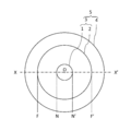
- FIG. 1 is a top view at the time.
- the distance on the lens when viewed in plan is referred to as a plan view distance.
- Reference numeral 1 denotes a near portion
- reference numeral 2 denotes a distance portion
- reference numeral 3 denotes an optical portion
- reference numeral 4 denotes a peripheral portion
- reference numeral 5 denotes a multifocal contact lens.
- the reference numerals are omitted.
- the optical center O of the lens is concentric, and a near portion is arranged in the center, and an annular far portion is arranged on the outer edge thereof.
- the optical center O coincides with the geometric center.
- an optical unit having a near portion and a far portion is configured.
- it has an annular peripheral part at the outer edge of the optical part.
- the peripheral part usually has a flange shape that easily enters the back of the eyelid when the lens is placed on the cornea. That is, the lens of this example is constituted by the optical part and the peripheral part.
- the optical part and the peripheral part are distinguished from each other in order to perform the above functions, and there is a clear boundary between the optical part and the peripheral part that can be visually confirmed, such as a step. Do not mean.
- the near vision frequency is obtained in the near vision area (NN ′ area).
- the distance power should be secured.
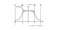
- FIG. 2 is a graph plotting the frequencies when the optical part of the conventional multifocal contact lens is viewed from the end F to the end F ′ in the X-X ′ direction.
- the horizontal axis indicates the distance from the optical center O at X-X ′ when the lens is viewed in plan.
- the vertical axis indicates the power of the lens (unit: diopter [D]). The power increases as it goes upward, and decreases as it goes downward.
- the power mentioned here refers to the power caused by the difference in the shape (curvature) of both surfaces of the lens.
- the portion where the frequency changes is positioned as a transition portion or an intermediate portion (reference numeral 104 in [FIG. 12] of Patent Document 2).
- the near power cannot be secured in the hatched portion of FIG. 2 (that is, the portion where the frequency starts to decrease). In other words, it may occur that the near vision cannot be sufficiently performed in the portion that should be viewed near.
- the position where the frequency is decreased as compared with FIG. 2 when viewed in the X direction and the X ′ direction can be moved away from the optical center O. In this way, it is possible to secure the near-use frequency in the preset near-use part (N-N ′ region).
- the distance portion disposed on the outer edge of the near portion is narrowed. In the end, it is impossible to secure the near-use frequency in the hatched portion in FIG. 3 (that is, the portion where the frequency starts to decrease).
- a multifocal contact lens In the optical part of a multifocal contact lens, it is very important to arrange the distance part and the near part in a balanced manner with respect to the pupil. And maintaining a good balance between the distance and near vision areas is not only related to multifocal contact lenses, but also important for other contact lenses or ophthalmic lenses including intraocular lenses. It is.
- An object of the present invention is to provide a balance between a near-use part and a distance-use part provided at an outer edge of the near-use part while sufficiently securing the near-use power when the near-use part is arranged in the center of the optical part.
- the distance part is arranged in the center of the optical part, the distance part and the near part provided on the outer edge of the distance part are balanced while the distance power is sufficiently secured in the distance part. To keep it good.
- the present inventors have intensively studied.
- the present inventors considered that the clue to solve this problem is to eliminate the hatched portion in FIG.
- the reason why the hatched portion in FIG. 2 occurs is that the reduction of the frequency must already be started in the near portion when viewed in the X direction. Therefore, the present inventors can increase the frequency in the near portion as shown in FIG. 4 (b) by increasing the frequency in the near portion before starting the decrease in the frequency.
- the near vision power is increased (in the direction where the nearer can be seen, that is, in the plus direction, eg, 5.00D ⁇ 5.10D), and then the distance is used. It is only necessary to decrease the frequency to the frequency, and conversely, when the distance portion is arranged at the center, for example, as shown in FIG. (Ie, 0.00D ⁇ ⁇ 0.10D), and then increase the power to the near power.
- the present invention described below has been adopted.
- each suitable aspect shown below can be combined suitably.
- the first aspect of the present invention is: A near portion having a near power for viewing a near distance, and a far portion having a distance power for viewing a distance farther than the near distance, the near portion or the
- the distance lens is arranged in the center, and what is not arranged in the center is an ophthalmic lens provided with an optical part arranged in an annular shape on the outer edge,
- the near portion or the far portion disposed in the center of the optical portion has a portion A that is weakened after increasing the power when viewed in the X direction from the center toward the periphery, and is opposite to the X direction.
- a second aspect of the present invention is the invention according to the first aspect,
- the near part is arranged in the center,
- the portion A and the portion A ′ have a shape in which the power is weakened until the power for distance use is reached after the power is increased toward the near power than the power for near use.
- a third aspect of the present invention is the invention according to the second aspect, There is only one place where the frequency is maximum in the part A, and there is only one place where the frequency is maximum in the part A ′.
- a fourth aspect of the present invention is the invention according to the second or third aspect,
- the planar distance between the portion where the frequency is maximum in the portion A and the portion where the frequency is maximum in the portion A ′ is 1.0 to 2.8 mm.
- a fifth aspect of the present invention is the invention according to any one of the second to fourth aspects,
- the difference between the maximum value of the frequency in the portion A and the near power is 0.05 to 0.25D, and the difference between the maximum value of the frequency in the portion A ′ and the near power is also 0.05. ⁇ 0.25D.
- a sixth aspect of the present invention is the invention according to the first aspect, In the optical part, the distance part is arranged in the center, The part A and the part A ′ have a shape in which the power is weakened until the power for the near vision is reached after the power is increased for the far vision rather than the power for the distance.
- a seventh aspect of the present invention is the invention according to the sixth aspect, There is only one place where the frequency is minimal in the part A, and there is only one part where the frequency is minimal in the part A ′.
- An eighth aspect of the present invention is the invention according to the sixth or seventh aspect,
- the planar view distance between the portion where the frequency is minimum in the portion A and the portion where the frequency is minimum in the portion A ′ is 1.0 to 2.8 mm.
- a ninth aspect of the present invention is the invention according to any one of the sixth to eighth aspects,
- the difference between the minimum value of the frequency in the portion A and the distance power is 0.05 to 0.25D, and the difference between the minimum value of the frequency in the portion A ′ and the distance power is also 0.05. ⁇ 0.25D.
- a tenth aspect of the present invention is the invention according to any one of the first to ninth aspects,
- the ophthalmic lens is a contact lens (a soft contact lens or a hard contact lens, preferably a soft contact lens).
- An eleventh aspect of the present invention is the invention according to any one of the first to ninth aspects,
- the ophthalmic lens is an intraocular lens.
- the twelfth aspect of the present invention provides A near portion having a near power for viewing a near distance, and a far portion having a distance power for viewing a distance farther than the near distance, the near portion or the
- the distance portion is arranged in the center, and what is not arranged in the center is a design method of an ophthalmic lens including an optical portion arranged in an annular shape on the outer edge,
- the near portion or the far portion disposed in the center of the optical portion has a portion A that is weakened after increasing the power when viewed in the X direction from the center toward the periphery, and is opposite to the X direction.
- This is an ophthalmic lens design method in which an ophthalmic lens is designed to have a weakened portion A ′ after increasing the power even when viewed in the X ′ direction from the center toward the periphery.
- a thirteenth aspect of the present invention is the invention according to the twelfth aspect,
- the near part is arranged in the center
- the ophthalmic lens is designed so as to decrease the power until the distance power is reached after the power is increased toward the near power than the near power.
- a fourteenth aspect of the present invention is the invention according to the thirteenth aspect, There are only one place where the frequency is maximum in the portion A, and there is only one place where the frequency is maximum in the portion A ′.
- a fifteenth aspect of the present invention is the invention according to the thirteenth or fourteenth aspect, A planar view distance between a portion where the power is maximum in the portion A and a portion where the power is maximum in the portion A ′ is 1.0 to 2.8 mm.
- a sixteenth aspect of the present invention is the invention according to any one of the thirteenth to fifteenth aspects,
- the difference between the maximum value of the frequency in the portion A and the near power is 0.05 to 0.25D, and the difference between the maximum value of the frequency in the portion A ′ and the near power is also 0.05 to 0.25D. 0.25D.
- a seventeenth aspect of the present invention is the invention according to the twelfth aspect,
- the distance part is arranged in the center
- the ophthalmic lens is designed so as to decrease the power until the power for near vision is reached after the power is increased toward the distance power than the distance power.
- An eighteenth aspect of the present invention is the invention according to the seventeenth aspect, Only one location where the frequency is minimal in the portion A is set, and only one location where the frequency is minimized in the portion A ′.
- a nineteenth aspect of the present invention is the invention according to the seventeenth or eighteenth aspect, A planar view distance between a portion where the frequency is minimum in the portion A and a location where the frequency is minimum in the portion A ′ is 1.0 to 2.8 mm.
- a twentieth aspect of the present invention is the invention according to any one of the seventeenth to nineteenth aspects,
- the difference between the minimum value of the frequency in the portion A and the distance power is 0.05 to 0.25D, and the difference between the minimum value of the frequency in the portion A ′ and the distance power is also 0.05 to 0.25D. 0.25D.
- a twenty-first aspect of the present invention is the invention according to any one of the twelfth to twentieth aspects,
- the ophthalmic lens is a contact lens (a soft contact lens or a hard contact lens, preferably a soft contact lens).
- a twenty-second aspect of the present invention is the invention according to any one of the twelfth to twentieth aspects,
- the ophthalmic lens is an intraocular lens.
- a twenty-third aspect of the present invention includes a design step of designing an ophthalmic lens by the ophthalmic lens design method according to any one of the twelfth to twenty-second aspects;
- an aspect of an ophthalmic lens set including a plurality of the above ophthalmic lenses is as follows.
- the previously mentioned suitable aspect with respect to the following aspects is also the aspect of this invention.
- the near portion or the far portion disposed in the center of the optical portion has a portion A that is weakened after increasing the power when viewed in the X direction from the center toward the periphery, and is opposite to the X direction.
- the near part is arranged in the center
- the portion A and the portion A ′ are: the frequency increases in the near portion and then decreases to the near power or less (preferably continues to decrease), then the frequency decreases until the distance power is reached. (Preferably the frequency keeps decreasing).
- the plane view distance is preferably 1.0 to 2.8 mm, the lower limit is more preferably 1.2 mm, still more preferably 1.4 mm, and very preferably 1.6 mm, and the upper limit is more
- the thickness is preferably 2.6 mm, more preferably 2.4 mm.
- the difference between the maximum value of the frequency in the portion A and the near power is 0.05 to 0.25D, and the difference between the maximum value of the frequency in the portion A ′ and the near power is also 0.05 to 0.25D.
- Each lower limit is more preferably 0.10D, still more preferably 0.12D, very preferably 0.15D, and the upper limit is more preferably 0.20D.
- the straight line XX ′ is rotated from 0 to 180 ° about the optical center O with respect to the lens, the distance is increased after increasing the power to nearer than the near power in the parts A and A ′.
- the portion having a shape whose power is weakened up to the frequency is 50 area% or more of the optical part, more preferably 80 area% or more, and further preferably 90 area% or more.
- the distance part is arranged in the center,
- the portion A and the portion A ′ are: the frequency decreases in the distance portion, then increases to the distance power or more (preferably continues to increase), and then increases to the near power (preferably Is the part where the frequency keeps increasing).
- a thirty-first aspect of the present invention provides the thirty-first aspect, It is preferable that there are two concave portions (that is, one convex portion on the top) when viewed on the frequency plot.
- the thirty-second aspect of the present invention is the thirty-first or thirty-first aspect
- the plane view distance is preferably 1.0 to 2.8 mm, the lower limit is more preferably 1.2 mm, still more preferably 1.4 mm, and very preferably 1.6 mm, and the upper limit is more
- the thickness is preferably 2.6 mm, more preferably 2.4 mm.
- the difference between the minimum frequency and the distance power in the portion A is 0.05 to 0.25D, and the difference between the minimum value and the distance power in the portion A ′ is also 0.05 to 0.25D.
- Each lower limit is more preferably 0.10D, still more preferably 0.12D, very preferably 0.15D, and the upper limit is more preferably 0.20D.
- the power of the distance A is increased after the power of the distance A is increased from the distance power to the distance power.
- the portion having a shape whose power is weakened up to the frequency is 50 area% or more of the optical part, more preferably 80 area% or more, and further preferably 90 area% or more.
- the ophthalmic lens is an intraocular lens;
- the ophthalmic lens includes a lens main body having the optical part and a support part extending from the lens main body.
- the support portions are, for example, two support portions extending in an arm shape from the lens body.
- a thirty-sixth aspect of the present invention provides A near portion having a near power for viewing a near distance, and a far portion having a distance power for viewing a distance farther than the near distance, the near portion or the
- the distance lens is arranged in the center, and what is not arranged in the center is an ophthalmic lens provided with an optical part arranged in an annular shape on the outer edge,
- the near portion or the far portion disposed in the center of the optical portion has a portion A that is weakened after increasing the power when viewed in the X direction from the center toward the periphery, and is opposite to the X direction.
- This is an ophthalmic lens or its design method and manufacturing method in which there is an inflection point of power when viewed in the X ′ direction from the center toward the periphery.
- the near portion when the near portion is arranged in the center of the optical portion, the balance between the near portion and the distance portion provided on the outer edge thereof is ensured while the near power is sufficiently secured in the near portion.
- the distance part is arranged in the center of the optical part, the distance part and the near part provided on the outer edge of the distance part are balanced while the distance power is sufficiently secured in the distance part. It becomes possible to keep it good.
- FIG. 1 is a schematic view of a conventional multifocal lens in plan view.
- FIG. 2 is a graph plotting the frequencies when the optical part of the conventional multifocal contact lens is viewed from the end F to the end F ′ in the X-X ′ direction.
- FIG. 3 is a diagram in which the position where the frequency is reduced as compared with FIG. 2 is further away from the optical center O when viewed in the X direction and the X ′ direction.
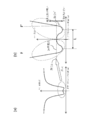
- FIG. 4A is a diagram plotting the frequency when the optical part of the multifocal contact lens of this embodiment is viewed from the end F to the end F ′ in the XX ′ direction
- FIG. FIG. 5 is an enlarged view of a near portion in FIG. FIG.
- FIG. 5 is a frequency plot diagram of another pattern in the multifocal contact lens of the present embodiment.
- FIG. 6 is a frequency plot diagram of another pattern in the multifocal contact lens of the present embodiment.
- FIG. 7 is a frequency plot diagram of another pattern in the multifocal contact lens of the present embodiment.
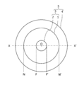
- FIG. 8 is a schematic view in plan view of a multifocal lens (having a distance portion at the center and a near portion at the outer edge thereof).
- FIG. 9A is a diagram plotting the frequency when the optical part of the multifocal contact lens of another embodiment is viewed from the end N to the end N ′ in the XX ′ direction, and FIG. It is an enlarged view of the distance part in Fig.9 (a).
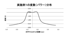
- FIG. 10 is a plot of the frequency when the optical part of the lens of Example 1 is viewed from the end F to the end F ′ in the X-X ′ direction.
- FIG. 11 is a plot of the frequency when the optical part of the lens of Comparative Example 1 is viewed from the end F to the end F ′ in the X-X ′ direction.
- FIG. 12 is a plot of the frequency when the optical part of the lens of Example 2 is viewed from the end F to the end F ′ in the X-X ′ direction.
- FIG. 13 is a plot of the frequency when the optical part of the lens of Comparative Example 2 is viewed from the end F to the end F ′ in the X-X ′ direction.
- ⁇ indicates a value that is greater than or equal to a predetermined value and less than or equal to a predetermined value.
- an ophthalmic lens (a contact lens or a lens body in an intraocular lens) handled in this specification has two surfaces facing each other. The side positioned on the retina side when the wearer wears the ophthalmic lens is referred to as “rear surface”, and the side positioned on the opposite object side is referred to as “front surface”.
- the frequency indicates power (unit: [D]).
- ⁇ increasing the near-use frequency '' means increasing the frequency in the direction in which the closer can be seen, that is, in the positive direction.
- “weakening the near-use power” refers to weakening in the direction in which the near is difficult to see, that is, in the plus direction, and reducing the power (eg, 5.10D ⁇ 5.00D).
- “increasing the distance power” refers to increasing the distance in the far direction, that is, in the minus direction, and decreasing the frequency (for example, 0. 00D ⁇ ⁇ 0.10D).
- “weakening the distance power” refers to weakening in the direction that makes it difficult to see far away, that is, in the positive direction, and means increasing the power (eg, ⁇ 0.10D ⁇ 0.00D).
- ⁇ increasing the frequency '' at the stage where it is undecided whether the near part or the far part is arranged in the center means increasing the near power or the far power.
- “Weak” means weakening the near power or the far power.
- Multifocal contact lens (multifocal lens)
- a multifocal contact lens (multifocal lens; hereinafter simply referred to as a lens) is mainly exemplified.
- the near portion is arranged in the center.
- the lens in the present embodiment like the conventional lens described above, is a substantially circular optical portion that mainly contributes to optical performance, and an annular peripheral portion located at the periphery of the optical portion. Is provided.
- the peripheral portion usually has a flange shape that easily enters the back of the eyelid when the lens is placed on the cornea.
- the optical unit includes a near vision unit having a near vision power for viewing a near distance, and a far vision system having a far vision power for viewing a distance (including infinity) farther than the near distance. It is what has.
- the near part is distribute
- the configuration in plan view is the same as that shown in FIG.
- an example is given in which the optical center O coincides with the geometric center of the lens, but the present invention is not limited thereto (the same applies hereinafter).
- FIG. 4A plotting the frequency when the optical part of the multifocal contact lens of this embodiment is viewed from the end F to the end F ′ in the XX ′ direction
- FIG. 4A is an enlarged view of the near part. This will be described with reference to b).
- the horizontal axis indicates the distance from the optical center O at XX ′ when the lens is viewed in plan.
- the vertical axis represents the lens power (unit: diopter [D]).
- the near portion is arranged at the center, and the far portion is arranged annularly on the outer edge thereof. Therefore, the optical center O is set to have a higher frequency than the distance portion.
- the distance power S and the addition power ADD are given, but the near power is a value of (S + ADD) ( The unit of each frequency is [D], and so on).
- the power is set as the value of the near power in the vicinity of the optical center O.
- the portion A and the portion A ′ mentioned here are, for example, the portion A in the near vision portion, after the frequency increases to a near vision frequency or less (preferably the frequency continues to decrease), then to the distance vision frequency. It refers to a portion where the frequency decreases (preferably the frequency continues to decrease). Referring to FIG. 4, the part A and the part A ′ are parts that exist in the near part (center) but also exist in the distance part that is the periphery thereof.
- the planar view distance L between the portion where the power is maximum in the portion A and the portion where the power is maximum in the portion A ′ is 1.0 to 2.8 mm.
- the lower limit is more preferably 1.2 mm, still more preferably 1.4 mm, and very preferably 1.6 mm, and the upper limit is more preferably 2.6 mm, still more preferably 2.4 mm.
- the planar viewing distance L may be set as appropriate according to the type of lens.
- the difference between the maximum value of the frequency in the portion A and the near power is 0.05 to 0.25D, and the difference between the maximum value of the frequency in the portion A ′ and the near power is also 0.05 to 0. .25D is preferred.
- Each lower limit is more preferably 0.10D, still more preferably 0.12D, very preferably 0.15D, and the upper limit is more preferably 0.20D.
- This definition makes it possible to fill the hatched portion shown in FIG. 2 sufficiently and reliably. However, this is not essential, and the above difference may be set as appropriate depending on the situation, and the above frequency difference may be different between the portion A and the portion A ′.
- the frequency plot of the distance portion at the outer edge there is a major feature in the behavior of frequency increase / decrease in the central one (here, the near portion). Thanks to this feature, it is possible to ensure a sufficiently wide space (here, the distance portion) disposed on the outer edge. Therefore, there is no particular limitation on the frequency plot of the distance portion at the outer edge.
- the frequency plot as shown in FIG. 4 (a) that is, the frequency gradually decreases at first, then the frequency decreases rapidly, and then the frequency decrease gradually decreases again. You may have a power plot where the power continues to decrease after reaching the power.
- FIG. 5 the frequency gradually decreases at the beginning, and then the frequency decreases a little abruptly, and finally the frequency continues to decrease after reaching the distance power.
- the frequency gradually decreases at the beginning, then the frequency decreases rapidly, the frequency decreases again, and finally the frequency changes after reaching the distance power. You may have a frequency plot that disappears.
- the frequency gradually decreases at the beginning, then the frequency decreases a little abruptly, and then the frequency decreases rapidly. You may have a frequency plot where the frequency continues to decrease.
- the present invention does not exclude the case where an annular near portion is provided at the peripheral edge in addition to the central near portion and the peripheral distance portion. Further, as will be described in detail later, the same applies when a distance portion is provided at the center, a near portion is provided at the periphery, and an annular distance portion is provided at the periphery.
- the near portion in the present embodiment is defined by the frequency plot.
- the near portion can be defined by the shape (curvature) of the front surface instead of the frequency plot.
- the surface (rear surface) in contact with the cornea must have a shape conforming to a surface (for example, a spherical surface or a toric surface) following the shape of the cornea.
- the power must be adjusted by the shape of the heel side surface (front surface).
- the characteristics of the power plot can be expressed by the shape (curvature) of the front surface of the lens, which is expressed as follows. “Near vision part with near power for viewing near distance and far distance part with distance power for seeing distance farther than near distance.
- An ophthalmic lens provided with an optical part arranged in an annular shape on the outer edge thereof, In the near portion, when viewed in the X direction from the center to the periphery, it has a portion A that is increased after decreasing the radius of curvature, and is in the direction opposite to the X direction and from the center to the periphery in the X ′ direction
- the planar view distance between the portion where the radius of curvature is minimal in the portion A and the portion where the radius of curvature is minimal in the portion A ′ is 1.0 to 2.8 mm.
- a suitable value of the difference between the minimum value of the radius of curvature in the portion A and the radius of curvature of the optical center depends largely on the central power (power), but as an example, it is 0.01 to 0.13 mm, preferably 0.03.
- the difference between the minimum value of the radius of curvature in the portion A ′ and the near power is, for example, 0.01 to 0.13 mm, preferably 0.03 to 0.11 mm.
- the power at the optical center is -3.00 D
- the base curve is 8.5 mm
- the refractive index is 1.45
- the center thickness is 0.10 mm.
- the lens of the present embodiment has a shape in which the power is weakened in the portion A and the portion A ′ until the distance power is reached after the power is increased to the near power rather than the near power.
- the portion having the shape is the entire optical unit (for convenience of explanation, it is also simply referred to as an optical unit). Is preferably 50 area% or more, more preferably 80 area% or more, and still more preferably 90 area% or more.
- area% refers to the area of the optical part when viewed in plan, and the straight line XX ′ with respect to the lens as viewed from the optical center when viewed in plan.
- a portion having the above-mentioned shape when rotated from 0 to 180 ° around the center for example, two fan-shaped portions surrounded by an arc at the outermost edge of the optical center O and the optical portion (at 0 ° to 180 °) It means the percentage of the total area of the part A, the part A ′)) lying between 180 ° and 360 °.
- a device power meter
- the distance portion is arranged in the center. Contrary to the above example, the idea of the present invention can also be applied to the case where the distance portion is arranged in the center and the near portion is arranged annularly on the outer edge thereof. is there. In addition, as a structure in plan view, the positions of the near portion and the far portion in FIG. 4 mentioned above are reversed. This is shown in FIG. Note that the portion A and the portion A ′ in this example are, for example, the portion A in the distance portion. After the frequency is decreased and then increased to the distance power or more (preferably continues to increase), It refers to a portion where the frequency increases (preferably the frequency continues to increase). In FIG. 9, the part A and the part A ′ are parts that exist in the distance part (center) but also exist in the near part that is the periphery thereof.
- FIG. 9A is a plot of the frequency when the optical part of the multifocal contact lens of this example is viewed from the end N to the end N ′ in the XX ′ direction, and FIG. 9B is an enlarged view of the distance part. ).
- the distance portion is disposed in the center, and the near portion is disposed annularly on the outer edge thereof.
- the optical center O is set to have a lower frequency than the near portion.
- the value of distance power S and addition power ADD and astigmatism power C when performing astigmatism correction
- the distance power S the distance power S.
- the power is increased to the far distance rather than the distance power (in the direction where the farther can be seen, that is, the negative direction).
- the frequency is weakened until it reaches the near power (it is weakened when viewed from a direction where the distance cannot be seen, that is, from the minus direction).
- the planar view distance L between the portion where the frequency is minimum in the portion A and the portion where the frequency is minimum in the portion A ′ is 1.0 to 2.8 mm.
- the lower limit is more preferably 1.2 mm, still more preferably 1.4 mm, and very preferably 1.6 mm, and the upper limit is more preferably 2.6 mm, still more preferably 2.4 mm.
- the planar viewing distance L may be set as appropriate according to the type of lens.
- the difference between the local minimum value and the distance power in the portion A is 0.05 to 0.25D, and the difference between the local minimum value and the distance power in the portion A ′ is also 0.05 to 0. .25D is preferred.
- Each lower limit is more preferably 0.10D, still more preferably 0.12D, very preferably 0.15D, and the upper limit is more preferably 0.20D.
- This definition makes it possible to fill the hatched portion shown in FIG. 2 sufficiently and reliably. However, this is not essential, and the above difference may be set as appropriate depending on the situation, and the above frequency difference may be different between the portion A and the portion A ′.
- the frequency plot of the near portion on the outer edge is not particularly limited.
- the frequency plots shown in FIGS. 5 to 7 may be reversed upside down.
- the lens of this example has a shape in which the power of the portion A and the portion A ′ is reduced to the near power after increasing the power to the far power rather than the distance power.
- the portion having the shape is preferably 50 area% or more of the optical portion, and 80 area % Or more is more preferable, and 90 area% or more is more preferable.
- the distance portion is specified by the shape (curvature) of the front surface instead of the frequency plot, the principle is the same as described in the case where the near portion is arranged in the center. And the distance portion are replaced, the maximum is replaced with the minimum, and “increased after decreasing (curvature radius)” is replaced with “decrease after increasing (curvature radius)”.
- the near portion when the near portion is arranged at the center, as described above, near the boundary with the far portion on the outer edge, when viewed in the X direction from the center to the periphery, it is closer than the near power.
- the power of near vision has a portion A in which the power is weakened until it reaches the distance power after increasing power, and is viewed in the X 'direction from the center to the periphery in the opposite direction to the X direction.
- a configuration having a portion A ′ in which the power is weakened until the power reaches the distance power after the power is increased toward the near vision.
- the lens of the present embodiment including the portions A and A ′ described above can be applied to either a soft contact lens or a hard contact lens, but the soft arrangement that hardly moves on the cornea.
- Contact lenses are more preferred in terms of providing sufficient optical performance and customer satisfaction for the wearer.
- the near-use part when the near-use part is arranged in the center of the optical part, the near-use part is provided at the near-use part and its outer edge while sufficiently securing the near-use power.
- the distance part is provided at the distance part and its outer edge while ensuring a sufficient distance power. It is possible to maintain a good balance with the near-use part.
- the design method has the following configuration. “A near part having a near power for viewing a near distance and a far part having a far power for viewing a distance farther than the near distance, the near part or The distance portion is arranged in the center, and what is not arranged in the center is a design method of an ophthalmic lens provided with an optical portion arranged annularly on the outer edge thereof, The near portion or the far portion disposed in the center of the optical portion has a portion A that is weakened after increasing the power when viewed in the X direction from the center toward the periphery, and is opposite to the X direction.
- a design process for designing an ophthalmic lens by the above-described ophthalmic lens design method (in some cases, appropriately combining each suitable example), and the designed ophthalmic lens are manufactured by a processing apparatus. And a processing step.
- a specific processing method it is sufficient to perform processing using a known lens processing apparatus.
- the intraocular lens is not particularly limited, and is an intraocular lens that is placed inside the lens capsule (in-the-bag), an intraocular lens that is placed outside the capsule (out-the-bag), or a sewn intraocular lens. Applicable to lenses and the like.
- an optical part is sufficient.
- an annular peripheral portion may be provided at the periphery of the optical portion that mainly contributes to the optical performance. Consists of an optical part and a support part that supports the optical part within the lens capsule.
- the intraocular lens includes the above-described optical unit and a support unit extending from the optical unit.
- the shape of the support part of a known intraocular lens may be adopted for the support part. For example, two support parts extending in an arm shape from the optical part may be provided in the optical part, and this may be used as an intraocular lens. Absent.
- the design method (manufacturing method) of the intraocular lens the design of the optical part is ⁇ 2. Since it is the same as that described in the contact lens design method (manufacturing method)>, the description is omitted. Although it relates to a specific design (manufacturing) method, it is sufficient to design by a known intraocular lens design method (processing apparatus). Also, ⁇ 1. The case classification (in the case where the near portion is arranged in the center and the case where the distance portion is arranged) and each preferred example described in the section “Contact Lens” are applicable to this item, and ⁇ 1. Since it overlaps with the description of the contact lens>, the description is omitted here.
- Eye lens set> The above contents can be sufficiently applied to a contact lens set including a plurality of contact lenses exemplified in the present embodiment and an intraocular lens set including a plurality of intraocular lenses also exemplified in the present embodiment. These lens sets are collectively referred to as “ophthalmic lens sets”.
- the technical idea of the present invention is sufficiently reflected also in an ophthalmic lens set in which a plurality of lenses exhibiting power behavior such as the contact lens (or intraocular lens) of the present embodiment described in detail above are prepared.
- a plurality of lenses exhibiting power behavior such as the contact lens (or intraocular lens) of the present embodiment described in detail above are prepared.
- all the ophthalmic lens sets constituting the ophthalmic lens set in the present embodiment exhibit the above-described frequency behavior. This is because the ophthalmic lens produced by chance and the ophthalmic lens set according to the present embodiment are completely different from each other even if one ophthalmic lens having the above-mentioned behavior is produced in the prior art. It means to do.
- the configuration of the ophthalmic lens set including a plurality of the above ophthalmic lenses is as follows.
- An ophthalmic lens set comprising a plurality of ophthalmic lenses having a portion A ′ that is weakened after increasing the power even when viewed in the X ′ direction from the center toward the periphery.
- both the X direction and the X ′ direction have a weakened part after increasing the power, but even if only one part has the part, the effect of the present invention is somewhat reduced. It is expected to play together.
- the contents are defined as follows.
- a near part having a near power for viewing a near distance and a far part having a far power for viewing a distance farther than the near distance the near part or The distance portion is arranged in the center, and what is not arranged in the center is an ophthalmic lens provided with an optical portion arranged in an annular shape on the outer edge, The near portion or the far portion disposed in the center of the optical portion has a portion A that is weakened after increasing the power when viewed in the X direction from the center toward the periphery, and is opposite to the X direction.
- the reason that the inflection point of the power exists in the X ′ direction is that the shape of the present invention is closer to that even if the power is not weakened after the power is strengthened in the X ′ direction. This is because it becomes easier to achieve the effect. And what defines a shape close to that is the expression “the inflection point of the frequency exists”.
- a soft contact lens (hereinafter simply referred to as a lens) which is a multifocal contact lens according to the present invention and a lens according to the prior art (not reflecting the technical idea of the present invention) are prepared.
- the test was conducted on the subject.
- the lens according to the present invention at this time is referred to as Example 1, and the lens according to the related art is referred to as Comparative Example 1.
- Example 2 Separately from the above test, males in their 60s were used as subjects, and the test was performed using the above lenses.
- the lens according to the present invention at this time is referred to as Example 2, and the lens according to the related art is referred to as Comparative Example 2.
- FIG. 10 is a plot of the frequencies when the optical part of the lens of Example 1 is viewed from the end F to the end F ′ in the XX ′ direction.
- FIG. 11 plots the frequency when the optical part of the lens of Comparative Example 1 is viewed from the end F to the end F ′ in the XX ′ direction.
- Example 1 the subject could be satisfied in both far vision and near vision.
- Comparative Example 1 the subject could not be satisfied in near vision. This is considered to be due to the fact that the near-use part is narrowed and the near-use power is insufficient, in other words, the distance-use part is secured too much to secure the distance-use power.
- FIG. 12 is a plot of the frequency when the optical part of the lens of Example 2 is viewed from the end F to the end F ′ in the XX ′ direction.
- FIG. 13 plots the frequencies when the optical part of the lens of Comparative Example 2 is viewed from the end F to the end F ′ in the XX ′ direction.
- Example 2 the subject could be satisfied with both far vision and near vision.
- Comparative Example 2 the subject could not be satisfied in near vision. This is because, as in Comparative Example 1, the near-use part is narrowed and the near-use power is insufficient, in other words, the distance-use part is too wide to secure the distance use power. I think that.
- the near portion when the near portion is arranged in the center of the optical portion, the near portion is provided at the near portion and its outer edge while sufficiently securing the near power in the near portion. It was found that the balance with the use part can be kept good. It should be noted that the same effect can be sufficiently expected when the distance portion is arranged in the center of the optical portion.
Landscapes
- Health & Medical Sciences (AREA)
- Ophthalmology & Optometry (AREA)
- Physics & Mathematics (AREA)
- General Health & Medical Sciences (AREA)
- General Physics & Mathematics (AREA)
- Optics & Photonics (AREA)
- Eyeglasses (AREA)
- Prostheses (AREA)
Abstract
Description
図1に示すように、レンズの光学中心Oを同心として中央に近用部、その外縁に環状の遠用部を配する。本例では光学中心Oを幾何中心と一致させる。こうして近用部および遠用部を有する光学部が構成される。そして光学部のさらに外縁に環状の周辺部を有する。周辺部はレンズを角膜上に載置した際に瞼の裏に入り込みやすいフランジ形状を有するのが通常である。つまり光学部と周辺部により本例のレンズは構成される。ただし、光学部と周辺部とは各々が上記の機能を奏するために区別されているのであって、光学部と周辺部との間に段差等のように目視で確認可能な明確な境目があるわけではない。
以上の知見を得た結果、以降に記載された本発明の構成を採用するに至った。なお、以下に示す好適な各態様は適宜組み合わせ可能である。
近方距離を見るための近用度数を備えた近用部と、近方距離よりも遠くの距離を見るための遠用度数を備えた遠用部とを有し、前記近用部または前記遠用部が中央に配され、中央に配されなかったものがその外縁に環状に配された光学部を備えた眼用レンズであって、
前記光学部の中央に配された前記近用部または前記遠用部において、中央から周辺に向かうX方向で見た時に度数を強めた後に弱めた部分Aを有し且つX方向とは正反対の方向であって中央から周辺に向かうX’方向で見た時にも度数を強めた後に弱めた部分A’を有する、眼用レンズである。
前記光学部においては前記近用部が中央に配され、
前記部分Aおよび前記部分A’においては前記近用度数よりも近用へと度数を強めた後に遠用度数に至るまで度数を弱めた形状を有する。
前記部分Aにおいて度数が極大となる箇所は1か所のみであり、且つ、前記部分A’においても度数が極大となる箇所は1か所のみである。
前記部分Aにおいて度数が極大となる箇所と、前記部分A’において度数が極大となる箇所との間の平面視距離は1.0~2.8mmである。
前記部分Aにおける度数の極大値と前記近用度数との差は0.05~0.25Dであり、且つ、前記部分A’における度数の極大値と前記近用度数との差も0.05~0.25Dである。
前記光学部においては前記遠用部が中央に配され、
前記部分Aおよび前記部分A’においては前記遠用度数よりも遠用へと度数を強めた後に近用度数に至るまで度数を弱めた形状を有する。
前記部分Aにおいて度数が極小となる箇所は1か所のみであり、且つ、前記部分A’においても度数が極小となる箇所は1か所のみである。
前記部分Aにおいて度数が極小となる箇所と、前記部分A’において度数が極小となる箇所との間の平面視距離は1.0~2.8mmである。
前記部分Aにおける度数の極小値と前記遠用度数との差は0.05~0.25Dであり、且つ、前記部分A’における度数の極小値と前記遠用度数との差も0.05~0.25Dである。
前記眼用レンズはコンタクトレンズ(ソフトコンタクトレンズまたはハードコンタクトレンズ。好ましくはソフトコンタクトレンズ。)である。
前記眼用レンズは眼内レンズである。
近方距離を見るための近用度数を備えた近用部と、近方距離よりも遠くの距離を見るための遠用度数を備えた遠用部とを有し、前記近用部または前記遠用部が中央に配され、中央に配されなかったものがその外縁に環状に配された光学部を備えた眼用レンズの設計方法であって、
前記光学部の中央に配された前記近用部または前記遠用部において、中央から周辺に向かうX方向で見た時に度数を強めた後に弱めた部分Aを有し且つX方向とは正反対の方向であって中央から周辺に向かうX’方向で見た時にも度数を強めた後に弱めた部分A’を有するように眼用レンズを設計する、眼用レンズの設計方法である。
前記光学部においては前記近用部を中央に配し、
前記部分Aおよび前記部分A’においては前記近用度数よりも近用へと度数を強めた後に遠用度数に至るまで度数を弱めるように眼用レンズを設計する。
前記部分Aにおいて度数が極大となる箇所は1か所のみとし、且つ、前記部分A’においても度数が極大となる箇所は1か所のみとする。
前記部分Aにおいて度数が極大となる箇所と、前記部分A’において度数が極大となる箇所との間の平面視距離を1.0~2.8mmとする。
前記部分Aにおける度数の極大値と前記近用度数との差を0.05~0.25Dとし、且つ、前記部分A’における度数の極大値と前記近用度数との差も0.05~0.25Dとする。
前記光学部においては前記遠用部を中央に配し、
前記部分Aおよび前記部分A’においては前記遠用度数よりも遠用へと度数を強めた後に近用度数に至るまで度数を弱めるように眼用レンズを設計する。
前記部分Aにおいて度数が極小となる箇所を1か所のみとし、且つ、前記部分A’においても度数が極小となる箇所を1か所のみとする。
前記部分Aにおいて度数が極小となる箇所と、前記部分A’において度数が極小となる箇所との間の平面視距離を1.0~2.8mmとする。
前記部分Aにおける度数の極小値と前記遠用度数との差を0.05~0.25Dとし、且つ、前記部分A’における度数の極小値と前記遠用度数との差も0.05~0.25Dとする。
前記眼用レンズはコンタクトレンズ(ソフトコンタクトレンズまたはハードコンタクトレンズ。好ましくはソフトコンタクトレンズ。)である。
前記眼用レンズは眼内レンズである。
設計された眼用レンズを加工装置により製造する加工工程と、
を有する、眼用レンズの製造方法である。
近方距離を見るための近用度数を備えた近用部と、近方距離よりも遠くの距離を見るための遠用度数を備えた遠用部とを有し、前記近用部または前記遠用部が中央に配され、中央に配されなかったものがその外縁に環状に配された光学部を備えた眼用レンズを複数備える眼用レンズセットであって、
前記光学部の中央に配された前記近用部または前記遠用部において、中央から周辺に向かうX方向で見た時に度数を強めた後に弱めた部分Aを有し且つX方向とは正反対の方向であって中央から周辺に向かうX’方向で見た時にも度数を強めた後に弱めた部分A’を有する眼用レンズを複数備える、眼用レンズセットである。
前記光学部においては前記近用部が中央に配され、
前記部分Aおよび前記部分A’とは、近用部内において度数が増加した後に近用度数以下へと減少し(好ましくは度数が減少し続け)た後、遠用度数に至るまで度数が減少す(好ましくは度数が減少し続け)る部分である。
度数プロットで見たときに上に凸部分が2か所(すなわち凹部分が1か所)存在するのが好ましい。
上記の平面視距離は1.0~2.8mmであるのが好ましく、下限は、より好ましくは1.2mm、さらに好ましくは1.4mm、非常に好ましくは1.6mmであり、上限は、より好ましくは2.6mm、さらに好ましくは2.4mmである。
部分Aにおける度数の極大値と近用度数との差は0.05~0.25Dであり、且つ、部分A’における度数の極大値と近用度数との差も0.05~0.25Dであるのが好ましい。各々の下限は、より好ましくは0.10D、さらに好ましくは0.12D、非常に好ましくは0.15Dであり、上限は、より好ましくは0.20Dである。
レンズに対して直線X-X’を光学中心Oを中心に0から180°まで回転させたときに、部分Aおよび部分A’において近用度数よりも近用へと度数を強めた後に遠用度数に至るまで度数を弱めた形状を有する部分が光学部の50面積%以上であるのが好ましく、80面積%以上がより好ましく、90面積%以上がさらに好ましい。
前記光学部においては前記遠用部が中央に配され、
前記部分Aおよび前記部分A’とは、遠用部内において度数が減少した後に遠用度数以上へと増加し(好ましくは増加し続け)た後、近用度数に至るまで度数が増加す(好ましくは度数が増加し続け)る部分である。
度数プロットで見たときに凹部分が2か所(すなわち上に凸部分が1か所)存在するのが好ましい。
上記の平面視距離は1.0~2.8mmであるのが好ましく、下限は、より好ましくは1.2mm、さらに好ましくは1.4mm、非常に好ましくは1.6mmであり、上限は、より好ましくは2.6mm、さらに好ましくは2.4mmである。
部分Aにおける度数の極小値と遠用度数との差は0.05~0.25Dであり、且つ、部分A’における度数の極小値と遠用度数との差も0.05~0.25Dであるのが好ましい。各々の下限は、より好ましくは0.10D、さらに好ましくは0.12D、非常に好ましくは0.15Dであり、上限は、より好ましくは0.20Dである。
レンズに対して直線X-X’を光学中心Oを中心に0から180°まで回転させたときに、部分Aおよび部分A’において遠用度数よりも遠用へと度数を強めた後に近用度数に至るまで度数を弱めた形状を有する部分が光学部の50面積%以上であるのが好ましく、80面積%以上がより好ましく、90面積%以上がさらに好ましい。
前記眼用レンズは眼内レンズであり、
前記眼用レンズは、前記光学部を有するレンズ本体と、前記レンズ本体から延在する支持部とを備える。
前記支持部は、例えば、レンズ本体から腕状に延在する2本の支持部である。
近方距離を見るための近用度数を備えた近用部と、近方距離よりも遠くの距離を見るための遠用度数を備えた遠用部とを有し、前記近用部または前記遠用部が中央に配され、中央に配されなかったものがその外縁に環状に配された光学部を備えた眼用レンズであって、
前記光学部の中央に配された前記近用部または前記遠用部において、中央から周辺に向かうX方向で見た時に度数を強めた後に弱めた部分Aを有し且つX方向とは正反対の方向であって中央から周辺に向かうX’方向で見た時には度数の変曲点が存在する、眼用レンズまたはその設計方法、製造方法である。
本実施形態においては、次の順序で説明を行う。
1.コンタクトレンズ
1-1.マルチフォーカルコンタクトレンズ(多焦点レンズ)
1-1-1.近用部を中央に配置
1-1-2.遠用部を中央に配置
1-2.その他のコンタクトレンズ
2.コンタクトレンズの設計方法(製造方法)
3.眼内レンズ(IOL)およびその設計方法(製造方法)
4.眼用レンズセット
5.変形例
また、本明細書にて扱う眼用レンズ(コンタクトレンズ、または眼内レンズにおけるレンズ本体)は互いに対向する二つの面を有する。該眼用レンズを装用者が装着した際に網膜側に位置する方を「後面」とし、その逆の物体側に位置する方を「前面」とする。
また、本明細書にて度数とはパワー(単位は[D])のことを指す。
その一方、中央に遠用部が配される場合、「遠用度数を強め」とは、より遠くが見える方向すなわちマイナス方向に強めることを指し、度数を減少させることを指す(例:0.00D→-0.10D)。逆に「遠用度数を弱め」とは、遠くが見えにくくなる方向すなわちプラス方向に見て弱めることを指し、度数を増加させることを指す(例:-0.10D→0.00D)。
つまり、中央に近用部が配されるか遠用部が配されるか未定の段階での「度数を強め」とは、近用度数または遠用度数を強めることを意味し、「度数を弱め」とは近用度数または遠用度数を弱めることを意味する。
1-1.マルチフォーカルコンタクトレンズ(多焦点レンズ)
本実施形態においてはマルチフォーカルコンタクトレンズ(多焦点レンズ。以降、単にレンズとも称する。)を主として例示する。
本実施形態におけるレンズは、先に説明した従来のレンズと同様、光学性能に主として寄与する略円形状の光学部と、該光学部の周縁に位置する環状の周辺部を備える。先ほど述べたように周辺部はレンズを角膜上に載置した際に瞼の裏に入り込みやすいフランジ形状を有するのが通常である。そして光学部は、近方距離を見るための近用度数を備えた近用部と、近方距離よりも遠くの距離(無限遠含む)を見るための遠用度数を備えた遠用部とを有するものである。そして本実施形態においては、近用部が中央に配され、遠用部がその外縁に環状に配された例を挙げる。なお、平面視の構成としては先に挙げた図1と同様である。本例においても光学中心Oをレンズの幾何中心と一致させた例を挙げるが、本発明はそれに限定されない(以降同様)。
本実施形態のマルチフォーカルコンタクトレンズの光学部をX-X’方向の端Fから端F’まで見た時の度数をプロットした図4(a)および近用部の拡大図である図4(b)を用いて説明する。図2と同様、横軸は、レンズを平面視した際のX-X’における光学中心Oからの距離を示す。縦軸は、レンズの度数(単位:ディオプター[D])を示す。
ただし、図4(b)に示すように、本実施形態のレンズは、部分Aおよび部分A’においては近用度数よりも近用へと度数を強めた後に遠用度数に至るまで度数を弱めた形状を有する。ここで言う部分Aおよび部分A’とは、近用部内において例えば部分Aだと度数が増加した後に近用度数以下へと減少し(好ましくは度数が減少し続け)た後、遠用度数に至るまで度数が減少す(好ましくは度数が減少し続け)る部分のことを指す。図4で言うと、部分Aおよび部分A’は、近用部(中央)に存在しつつもその周辺である遠用部にもわたって存在する部分である。
その一方で、図5に示すように、はじめは緩やかに度数が減少し、その後で少しばかり急に度数が減少し、最終的には遠用度数へと至った後も度数が減少し続けるという度数プロットを有しても構わない。
また、図6に示すように、はじめは緩やかに度数が減少し、その後で急激に度数が減少し、再び度数の減少が緩やかとなり、最終的には遠用度数へと至った後は度数変化が無くなるという度数プロットを有しても構わない。
また、図7に示すように、はじめは緩やかに度数が減少し、その後で少しばかり急に度数が減少したのちに急激に度数が減少し、最終的には遠用度数へと至った後も度数が減少し続けるという度数プロットを有しても構わない。
さらに言うと、中央の近用部、周縁の遠用部に加え、そのさらに周縁に環状の近用部を設ける場合も本発明は排除しない。また、後で詳述するが中央に遠用部を設け、周縁に近用部、そのさらに周縁に環状の遠用部を設ける場合も同様である。
近用部において、中央から周辺に向かうX方向で見た時に曲率半径を減少させた後に増加させた部分Aを有し且つX方向とは正反対の方向であって中央から周辺に向かうX’方向で見た時にも曲率半径を減少させた後に増加させた部分A’を有する、眼用レンズ。
好ましくは、
部分Aにおいて曲率半径が極小となる箇所は1か所のみであり、且つ、部分A’においても曲率半径が極小となる箇所は1か所のみである。
好ましくは、
部分Aにおいて曲率半径が極小となる箇所と、部分A’において曲率半径が極小となる箇所との間の平面視距離は1.0~2.8mmである。
好ましくは、
部分Aにおける曲率半径の極小値と光学中心の曲率半径との差の好適な値は、中央の度数(パワー)によるところが大きいが、一例としては0.01~0.13mm、好ましくは0.03~0.11mmであり、部分A’における曲率半径の極小値と近用度数との差も一例としては0.01~0.13mm、好ましくは0.03~0.11mmである。その際の設定は、光学中心のパワーを-3.00D、ベースカーブ8.5mm、屈折率1.45、中心肉厚0.10mmとしている。」
ちなみに度数にて規定した場合の好適例を、曲率半径を用いた場合に対し、適宜度数を曲率半径へと変換したうえで適用することも可能である。
なお、本明細書において「面積%」とは、平面視した際の光学部の面積に対し、同じく平面視した際の、光学中心からみて、レンズに対して直線X-X’を光学中心Oを中心に0から180°まで回転させたときに上記の形状を有する部分(例えば光学中心Oと光学部の最外縁の円弧で囲まれる扇形の2か所の部分(0°~180°にある部分A、180°~360°にある部分A’))の面積の合計の百分率を意味する。
また、レンズにおける光学部と周辺部との間には、先に述べたように目視で確認可能な境目があるわけではないが、レンズの度数を測定する装置(パワーメータ)を使用することにより判別可能である。
上記の例とは逆に、遠用部が中央に配され、近用部がその外縁に環状に配された場合についても本発明の思想を適用することが可能である。なお、平面視の構成としては先に挙げた図4における近用部と遠用部の位置を逆転させたものとなる。それを表したのが図8である。
なお、本例における部分Aおよび部分A’とは、遠用部内において例えば部分Aだと度数が減少した後に遠用度数以上へと増加し(好ましくは増加し続ける)た後、近用度数に至るまで度数が増加す(好ましくは度数が増加し続け)る部分のことを指す。図9で言うと、部分Aおよび部分A’は、遠用部(中央)に存在しつつもその周辺である近用部にもわたって存在する部分である。
ただし、図9(b)に示すように、本例のレンズは、部分Aおよび部分A’においては遠用度数よりも遠用へと度数を強め(より遠くが見える方向すなわちマイナス方向に強める。)た後に近用度数に至るまで度数を弱め(遠くが見えない方向すなわちマイナス方向から見て弱める。)た形状を有する。
本実施形態においてはマルチフォーカルコンタクトレンズを例示したが、それ以外のコンタクトレンズにも本発明の技術的思想を適用することが可能である。
なお、遠用部を中央に配置して外縁に近用部を配置した場合についても本発明の技術的思想を適用することが可能である。その他の内容は、<1-1-2.遠用部を中央に配置>の項目にて述べた内容と重複するため省略する。
上記の内容は、コンタクトレンズの設計方法や製造方法においても十分に適用可能である。例えば設計方法については以下の構成となる。
「近方距離を見るための近用度数を備えた近用部と、近方距離よりも遠くの距離を見るための遠用度数を備えた遠用部とを有し、前記近用部または前記遠用部が中央に配され、中央に配されなかったものがその外縁に環状に配された光学部を備えた眼用レンズの設計方法であって、
前記光学部の中央に配された前記近用部または前記遠用部において、中央から周辺に向かうX方向で見た時に度数を強めた後に弱めた部分Aを有し且つX方向とは正反対の方向であって中央から周辺に向かうX’方向で見た時にも度数を強めた後に弱めた部分A’を有するように眼用レンズを設計する、眼用レンズの設計方法。」
本発明の技術的思想は、眼内レンズ(IOL)およびその設計方法(製造方法)においても十分に適用可能である。眼内レンズとしては特に限定は無く、水晶体嚢内に配置する形式(イン ザ バッグ)の眼内レンズや、嚢外に配置する形式(アウト ザ バッグ)の眼内レンズや、縫着型の眼内レンズ等々に適用可能である。
上記の内容は、本実施形態にて例示したコンタクトレンズを複数備えるコンタクトレンズセットや、同じく本実施形態にて例示した眼内レンズを複数備える眼内レンズセットにおいても十分に適用可能である。これらのレンズセットを総称して「眼用レンズセット」と称する。
見方を変えると、本実施形態における眼用レンズセットを構成するすべての眼用レンズセットが上述のような度数の挙動を示す。これは、従来技術において上記の度数の挙動を示す眼用レンズが1枚作製されたとしても、偶々作製されたこの眼用レンズと、本実施形態における眼用レンズセットとでは、構成として全く相違することを意味する。
前記光学部の中央に配された前記近用部または前記遠用部において、中央から周辺に向かうX方向で見た時に度数を強めた後に弱めた部分Aを有し且つX方向とは正反対の方向であって中央から周辺に向かうX’方向で見た時にも度数を強めた後に弱めた部分A’を有する眼用レンズを複数備える、眼用レンズセット。」
本発明は上記の各例に限定されることはなく、上記の各例および好適例を適宜組み合わせてももちろん構わない。また、先に挙げた実施形態だと、X方向にもX’方向にも、度数を強めた後に弱めた部分を有するが、一方にのみ該部分を有しても本発明の効果を多少なりとも奏することが期待される。この内容を規定すると以下のようになる。
「近方距離を見るための近用度数を備えた近用部と、近方距離よりも遠くの距離を見るための遠用度数を備えた遠用部とを有し、前記近用部または前記遠用部が中央に配され、中央に配されなかったものがその外縁に環状に配された光学部を備えた眼用レンズであって、
前記光学部の中央に配された前記近用部または前記遠用部において、中央から周辺に向かうX方向で見た時に度数を強めた後に弱めた部分Aを有し且つX方向とは正反対の方向であって中央から周辺に向かうX’方向で見た時には度数の変曲点が存在する、眼用レンズまたはその設計方法、製造方法。」
ちなみにここでX’方向で度数の変曲点を存在させている理由としては、X’方向にて度数を強めた後に弱めたまでは行かないにしてもそれに近い形状がある方が本発明の効果を奏しやすくなるためである。そして該それに近い形状を規定したものが“度数の変曲点が存在”という表現である。
また、上記試験とは別に、60代男性を被検者とし、上記の各レンズを用いて試験を行った。このときの本発明に係るレンズを実施例2、従来技術に係るレンズを比較例2とした。
まず、50代男性の完全矯正値を設定した。なお完全矯正値とは被検者にとって最も物が見えやすい条件のことを意味する。以下、右目(VD)および左目(VS)における完全矯正値を示す。
VD=1.5×S+0.50D(頂点間距離を考慮した有効加入度数+1.20D)
VS=1.5×S+0.50D(頂点間距離を考慮した有効加入度数+1.20D)
上記の各式の意味は、球面度数Sを0.50Dとすることにより視力1.5を達成できることを意味する。また、頂点間距離を考慮した有効加入度数+1.20Dとは、眼鏡レンズにおいて頂点間距離12mmであった場合をコンタクトレンズの場合に対応させた場合の補正量を表す。
R:BC8.7mm/P+0.50D/ADD+1.50(光学部において、中央に近用部を配し、その周縁に遠用部を配するレンズ)
L:BC8.7mm/P+0.50D/ADD+1.50(光学部において、中央に近用部を配し、その周縁に遠用部を配するレンズ)
なお、実施例1のレンズの光学部をX-X’方向の端Fから端F’まで見た時の度数をプロットしたのが図10である。また、実施例1のレンズにおいては、レンズに対して直線X-X’を光学中心Oを中心に0から180°まで回転させたときに、光学部(全体)が該形状を有するようにした。
同様に、比較例1のレンズの光学部をX-X’方向の端Fから端F’まで見た時の度数をプロットしたのが図11である。

表1に示すように、実施例1においては遠方視、近方視ともに被検者を満足させることができた。その一方、比較例1においては近方視において被検者を満足させることができなかった。これは、近用部が狭くなり且つ近用度数が不足してしまったこと、言い換えると遠用度数を確保すべく遠用部を広く確保しすぎてしまったことに起因すると考えられる。
まず、60代男性の完全矯正値を設定した。なお完全矯正値とは被検者にとって最も物が見えやすい条件のことを意味する。以下、右目(VD)および左目(VS)における完全矯正値を示す。
VD=1.5×S-1.25D(頂点間距離を考慮した有効加入度数+1.80D)
VS=1.5×S-1.25D(頂点間距離を考慮した有効加入度数+1.80D)
R:BC8.7mm/P-1.25D/ADD+2.00(光学部において、中央に近用部を配し、その周縁に遠用部を配するレンズ)
L:BC8.7mm/P-1.25D/ADD+2.00(光学部において、中央に近用部を配し、その周縁に遠用部を配するレンズ)
なお、実施例2のレンズの光学部をX-X’方向の端Fから端F’まで見た時の度数をプロットしたのが図12である。また、実施例2のレンズにおいては、レンズに対して直線X-X’を光学中心Oを中心に0から180°まで回転させたときに、光学部(全体)が該形状を有するようにした。
同様に、比較例2のレンズの光学部をX-X’方向の端Fから端F’まで見た時の度数をプロットしたのが図13である。

表2に示すように、実施例2においては遠方視、近方視ともに被検者を満足させることができた。その一方、比較例2においてはやはり近用視において被検者を満足させることができなかった。これは、比較例1と同様に近用部が狭くなり且つ近用度数が不足してしまったこと、言い換えると遠用度数を確保すべく遠用部を広く確保しすぎてしまったことに起因すると考えられる。
以上の結果、各実施例によれば、光学部の中央に近用部が配された場合、近用部において近用度数を十分に確保しつつも近用部とその外縁に設けられた遠用部とのバランスを良好に保つことが可能となることがわかった。なお、光学部の中央に遠用部が配された場合にも同様の効果が十分に期待できる。
2………遠用部
3………光学部
4………周辺部
5………マルチフォーカルコンタクトレンズ
Claims (24)
- 近方距離を見るための近用度数を備えた近用部と、近方距離よりも遠くの距離を見るための遠用度数を備えた遠用部とを有し、前記近用部または前記遠用部が中央に配され、中央に配されなかったものがその外縁に環状に配された光学部を備えた眼用レンズであって、
前記光学部の中央に配された前記近用部または前記遠用部において、中央から周辺に向かうX方向で見た時に度数を強めた後に弱めた部分Aを有し且つX方向とは正反対の方向であって中央から周辺に向かうX’方向で見た時にも度数を強めた後に弱めた部分A’を有する、眼用レンズ。 - 前記光学部においては前記近用部が中央に配され、
前記部分Aおよび前記部分A’においては前記近用度数よりも近用へと度数を強めた後に遠用度数に至るまで度数を弱めた形状を有する、請求項1に記載の眼用レンズ。 - 前記部分Aにおいて度数が極大となる箇所は1か所のみであり、且つ、前記部分A’においても度数が極大となる箇所は1か所のみである、請求項2に記載の眼用レンズ。
- 前記部分Aにおいて度数が極大となる箇所と、前記部分A’において度数が極大となる箇所との間の平面視距離は1.0~2.8mmである、請求項2または3に記載の眼用レンズ。
- 前記部分Aにおける度数の極大値と前記近用度数との差は0.05~0.25Dであり、且つ、前記部分A’における度数の極大値と前記近用度数との差も0.05~0.25Dである、請求項2~4のいずれかに記載の眼用レンズ。
- 前記光学部においては前記遠用部が中央に配され、
前記部分Aおよび前記部分A’においては前記遠用度数よりも遠用へと度数を強めた後に近用度数に至るまで度数を弱めた形状を有する、請求項1に記載の眼用レンズ。 - 前記部分Aにおいて度数が極小となる箇所は1か所のみであり、且つ、前記部分A’においても度数が極小となる箇所は1か所のみである、請求項6に記載の眼用レンズ。
- 前記部分Aにおいて度数が極小となる箇所と、前記部分A’において度数が極小となる箇所との間の平面視距離は1.0~2.8mmである、請求項6または7に記載の眼用レンズ。
- 前記部分Aにおける度数の極小値と前記遠用度数との差は0.05~0.25Dであり、且つ、前記部分A’における度数の極小値と前記遠用度数との差も0.05~0.25Dである、請求項6~8のいずれかに記載の眼用レンズ。
- 前記眼用レンズはコンタクトレンズである、請求項1~9のいずれかに記載の眼用レンズ。
- 前記眼用レンズは眼内レンズである、請求項1~9のいずれかに記載の眼用レンズ。
- 近方距離を見るための近用度数を備えた近用部と、近方距離よりも遠くの距離を見るための遠用度数を備えた遠用部とを有し、前記近用部または前記遠用部が中央に配され、中央に配されなかったものがその外縁に環状に配された光学部を備えた眼用レンズの設計方法であって、
前記光学部の中央に配された前記近用部または前記遠用部において、中央から周辺に向かうX方向で見た時に度数を強めた後に弱めた部分Aを有し且つX方向とは正反対の方向であって中央から周辺に向かうX’方向で見た時にも度数を強めた後に弱めた部分A’を有するように眼用レンズを設計する、眼用レンズの設計方法。 - 前記光学部においては前記近用部を中央に配し、
前記部分Aおよび前記部分A’においては前記近用度数よりも近用へと度数を強めた後に遠用度数に至るまで度数を弱めるように眼用レンズを設計する、請求項12に記載の眼用レンズの設計方法。 - 前記部分Aにおいて度数が極大となる箇所は1か所のみとし、且つ、前記部分A’においても度数が極大となる箇所は1か所のみとする、請求項13に記載の眼用レンズの設計方法。
- 前記部分Aにおいて度数が極大となる箇所と、前記部分A’において度数が極大となる箇所との間の平面視距離を1.0~2.8mmとする、請求項13または14に記載の眼用レンズの設計方法。
- 前記部分Aにおける度数の極大値と前記近用度数との差を0.05~0.25Dとし、且つ、前記部分A’における度数の極大値と前記近用度数との差も0.05~0.25Dとする、請求項13~15のいずれかに記載の眼用レンズの設計方法。
- 前記光学部においては前記遠用部を中央に配し、
前記部分Aおよび前記部分A’においては前記遠用度数よりも遠用へと度数を強めた後に近用度数に至るまで度数を弱めるように眼用レンズを設計する、請求項12に記載の眼用レンズの設計方法。 - 前記部分Aにおいて度数が極小となる箇所を1か所のみとし、且つ、前記部分A’においても度数が極小となる箇所を1か所のみとする、請求項17に記載の眼用レンズの設計方法。
- 前記部分Aにおいて度数が極小となる箇所と、前記部分A’において度数が極小となる箇所との間の平面視距離を1.0~2.8mmとする、請求項17または18に記載の眼用レンズの設計方法。
- 前記部分Aにおける度数の極小値と前記遠用度数との差を0.05~0.25Dとし、且つ、前記部分A’における度数の極小値と前記遠用度数との差も0.05~0.25Dとする、請求項17~19のいずれかに記載の眼用レンズの設計方法。
- 前記眼用レンズはコンタクトレンズである、請求項12~20のいずれかに記載の眼用レンズの設計方法。
- 前記眼用レンズは眼内レンズである、請求項12~20のいずれかに記載の眼用レンズの設計方法。
- 請求項12~22のいずれかに記載の眼用レンズの設計方法によって眼用レンズを設計する設計工程と、
設計された眼用レンズを加工装置により製造する加工工程と、
を有する、眼用レンズの製造方法。 - 近方距離を見るための近用度数を備えた近用部と、近方距離よりも遠くの距離を見るための遠用度数を備えた遠用部とを有し、前記近用部または前記遠用部が中央に配され、中央に配されなかったものがその外縁に環状に配された光学部を備えた眼用レンズを複数備える眼用レンズセットであって、
前記光学部の中央に配された前記近用部または前記遠用部において、中央から周辺に向かうX方向で見た時に度数を強めた後に弱めた部分Aを有し且つX方向とは正反対の方向であって中央から周辺に向かうX’方向で見た時にも度数を強めた後に弱めた部分A’を有する眼用レンズを複数備える、眼用レンズセット。
Priority Applications (5)
| Application Number | Priority Date | Filing Date | Title |
|---|---|---|---|
| KR1020197007872A KR102646965B1 (ko) | 2017-01-24 | 2017-02-02 | 안용 렌즈, 그 설계 방법, 그 제조 방법, 및 안용 렌즈 세트 |
| EP17894633.1A EP3575858B1 (en) | 2017-01-24 | 2017-02-02 | Ophthalmic lens, method of design therefor, method of manufacture therefor, and ophthalmic lens set |
| CN201780060795.7A CN109791308B (zh) | 2017-01-24 | 2017-02-02 | 眼用透镜、眼用透镜的设计方法、眼用透镜的制造方法及眼用透镜组 |
| ES17894633T ES3056718T3 (en) | 2017-01-24 | 2017-02-02 | Ophthalmic lens, method of design therefor, method of manufacture therefor, and ophthalmic lens set |
| US16/480,224 US11409132B2 (en) | 2017-01-24 | 2017-02-02 | Ophthalmic lens, method for designing the same, method for manufacturing the same, and ophthalmic lens set |
Applications Claiming Priority (2)
| Application Number | Priority Date | Filing Date | Title |
|---|---|---|---|
| JP2017-009956 | 2017-01-24 | ||
| JP2017009956A JP6188974B1 (ja) | 2017-01-24 | 2017-01-24 | 眼用レンズ、その設計方法、その製造方法、および眼用レンズセット |
Publications (1)
| Publication Number | Publication Date |
|---|---|
| WO2018138931A1 true WO2018138931A1 (ja) | 2018-08-02 |
Family
ID=59720491
Family Applications (1)
| Application Number | Title | Priority Date | Filing Date |
|---|---|---|---|
| PCT/JP2017/003758 Ceased WO2018138931A1 (ja) | 2017-01-24 | 2017-02-02 | 眼用レンズ、その設計方法、その製造方法、および眼用レンズセット |
Country Status (7)
| Country | Link |
|---|---|
| US (1) | US11409132B2 (ja) |
| EP (1) | EP3575858B1 (ja) |
| JP (1) | JP6188974B1 (ja) |
| KR (1) | KR102646965B1 (ja) |
| CN (1) | CN109791308B (ja) |
| ES (1) | ES3056718T3 (ja) |
| WO (1) | WO2018138931A1 (ja) |
Cited By (2)
| Publication number | Priority date | Publication date | Assignee | Title |
|---|---|---|---|---|
| WO2023162957A1 (ja) | 2022-02-24 | 2023-08-31 | Hoya株式会社 | 眼用レンズ、その設計方法、その製造方法、および眼用レンズセット |
| WO2023162956A1 (ja) | 2022-02-24 | 2023-08-31 | Hoya株式会社 | 眼用レンズ、その設計方法、その製造方法、および眼用レンズセット |
Families Citing this family (3)
| Publication number | Priority date | Publication date | Assignee | Title |
|---|---|---|---|---|
| JP6559866B1 (ja) * | 2018-10-11 | 2019-08-14 | Hoya株式会社 | 眼用レンズ、その設計方法、その製造方法、および眼用レンズセット |
| WO2020179332A1 (ja) * | 2019-03-06 | 2020-09-10 | 株式会社ニデック | 眼内レンズとその製造方法 |
| EP3958045A1 (en) * | 2020-08-18 | 2022-02-23 | Hoya Corporation | Ophthalmic lens |
Citations (5)
| Publication number | Priority date | Publication date | Assignee | Title |
|---|---|---|---|---|
| JPH05181096A (ja) * | 1991-12-28 | 1993-07-23 | Menicon Co Ltd | マルチフォーカル眼用レンズおよびその製作方法 |
| JP2006505011A (ja) | 2002-10-31 | 2006-02-09 | ジョンソン・アンド・ジョンソン・ビジョン・ケア・インコーポレイテッド | 多焦点眼用レンズの設計方法 |
| WO2006129707A1 (ja) | 2005-06-03 | 2006-12-07 | Hoya Healthcare Corporation | 眼用レンズ |
| JP2012093522A (ja) * | 2010-10-26 | 2012-05-17 | Hoya Corp | 累進多焦点コンタクトレンズ |
| WO2014128744A1 (ja) * | 2013-02-19 | 2014-08-28 | 株式会社メニコン | 老視用コンタクトレンズセットおよび老視用コンタクトレンズの選択方法 |
Family Cites Families (3)
| Publication number | Priority date | Publication date | Assignee | Title |
|---|---|---|---|---|
| CN101583325B (zh) * | 2006-12-27 | 2012-01-04 | Hoya株式会社 | 多焦点眼用透镜 |
| CN102119354B (zh) * | 2008-08-11 | 2013-06-19 | 诺瓦提斯公司 | 用于防止或延缓近视发展的透镜设计和方法 |
| TWI588560B (zh) * | 2012-04-05 | 2017-06-21 | 布萊恩荷登視覺協會 | 用於屈光不正之鏡片、裝置、方法及系統 |
-
2017
- 2017-01-24 JP JP2017009956A patent/JP6188974B1/ja active Active
- 2017-02-02 US US16/480,224 patent/US11409132B2/en active Active
- 2017-02-02 ES ES17894633T patent/ES3056718T3/es active Active
- 2017-02-02 EP EP17894633.1A patent/EP3575858B1/en active Active
- 2017-02-02 KR KR1020197007872A patent/KR102646965B1/ko active Active
- 2017-02-02 CN CN201780060795.7A patent/CN109791308B/zh active Active
- 2017-02-02 WO PCT/JP2017/003758 patent/WO2018138931A1/ja not_active Ceased
Patent Citations (5)
| Publication number | Priority date | Publication date | Assignee | Title |
|---|---|---|---|---|
| JPH05181096A (ja) * | 1991-12-28 | 1993-07-23 | Menicon Co Ltd | マルチフォーカル眼用レンズおよびその製作方法 |
| JP2006505011A (ja) | 2002-10-31 | 2006-02-09 | ジョンソン・アンド・ジョンソン・ビジョン・ケア・インコーポレイテッド | 多焦点眼用レンズの設計方法 |
| WO2006129707A1 (ja) | 2005-06-03 | 2006-12-07 | Hoya Healthcare Corporation | 眼用レンズ |
| JP2012093522A (ja) * | 2010-10-26 | 2012-05-17 | Hoya Corp | 累進多焦点コンタクトレンズ |
| WO2014128744A1 (ja) * | 2013-02-19 | 2014-08-28 | 株式会社メニコン | 老視用コンタクトレンズセットおよび老視用コンタクトレンズの選択方法 |
Non-Patent Citations (1)
| Title |
|---|
| See also references of EP3575858A4 |
Cited By (4)
| Publication number | Priority date | Publication date | Assignee | Title |
|---|---|---|---|---|
| WO2023162957A1 (ja) | 2022-02-24 | 2023-08-31 | Hoya株式会社 | 眼用レンズ、その設計方法、その製造方法、および眼用レンズセット |
| WO2023162956A1 (ja) | 2022-02-24 | 2023-08-31 | Hoya株式会社 | 眼用レンズ、その設計方法、その製造方法、および眼用レンズセット |
| JP2023122709A (ja) * | 2022-02-24 | 2023-09-05 | Hoya株式会社 | 眼用レンズ、その設計方法、その製造方法、および眼用レンズセット |
| JP2023122708A (ja) * | 2022-02-24 | 2023-09-05 | Hoya株式会社 | 眼用レンズ、その設計方法、その製造方法、および眼用レンズセット |
Also Published As
| Publication number | Publication date |
|---|---|
| CN109791308A (zh) | 2019-05-21 |
| US11409132B2 (en) | 2022-08-09 |
| EP3575858C0 (en) | 2025-11-12 |
| JP6188974B1 (ja) | 2017-08-30 |
| US20200004045A1 (en) | 2020-01-02 |
| EP3575858A4 (en) | 2020-09-09 |
| JP2018120040A (ja) | 2018-08-02 |
| CN109791308B (zh) | 2021-02-12 |
| EP3575858B1 (en) | 2025-11-12 |
| KR20190104309A (ko) | 2019-09-09 |
| KR102646965B1 (ko) | 2024-03-12 |
| ES3056718T3 (en) | 2026-02-24 |
| EP3575858A1 (en) | 2019-12-04 |
Similar Documents
| Publication | Publication Date | Title |
|---|---|---|
| JP7466450B2 (ja) | レンズ要素 | |
| KR101199425B1 (ko) | 변형된 각막을 재성형하기 위한 콘택트 렌즈 | |
| KR101627476B1 (ko) | 안경 렌즈 요소 | |
| US20240280832A1 (en) | Lens element | |
| US8113652B2 (en) | Contact lens with meridional sagittal variation and methods for making and using the same | |
| JP6646531B2 (ja) | コンタクトレンズおよびその製造方法 | |
| JP2023519520A (ja) | レンズ要素 | |
| JP6559866B1 (ja) | 眼用レンズ、その設計方法、その製造方法、および眼用レンズセット | |
| JP6188974B1 (ja) | 眼用レンズ、その設計方法、その製造方法、および眼用レンズセット | |
| US9417463B2 (en) | Lens design and method for minimizing visual acuity variation experienced by myopia progressors | |
| WO2017149512A1 (en) | Systems and methods for fitting contact lenses | |
| JP2017003986A (ja) | 最適化された性能を有するコンタクトレンズ及びデザインの方法 | |
| CN116880085B (zh) | 一种接触镜 | |
| TWI871281B (zh) | 鏡片元件 | |
| KR20220006632A (ko) | 체적 변화가 감소된 소프트 콘택트 렌즈 | |
| JP2024116390A (ja) | エッジトゥエッジのフォトクロミックソフトコンタクトレンズを設計する方法 | |
| WO2023162956A1 (ja) | 眼用レンズ、その設計方法、その製造方法、および眼用レンズセット | |
| KR20240149885A (ko) | 안용 렌즈, 그 설계 방법, 그 제조 방법, 및 안용 렌즈 세트 | |
| KR20250054592A (ko) | 변형된 각막 맞춤형 콘택트 렌즈 |
Legal Events
| Date | Code | Title | Description |
|---|---|---|---|
| 121 | Ep: the epo has been informed by wipo that ep was designated in this application |
Ref document number: 17894633 Country of ref document: EP Kind code of ref document: A1 |
|
| ENP | Entry into the national phase |
Ref document number: 20197007872 Country of ref document: KR Kind code of ref document: A |
|
| NENP | Non-entry into the national phase |
Ref country code: DE |
|
| ENP | Entry into the national phase |
Ref document number: 2017894633 Country of ref document: EP Effective date: 20190826 |
|
| WWG | Wipo information: grant in national office |
Ref document number: 2017894633 Country of ref document: EP |