WO2018138936A1 - ヒートシンク - Google Patents
ヒートシンク Download PDFInfo
- Publication number
- WO2018138936A1 WO2018138936A1 PCT/JP2017/010978 JP2017010978W WO2018138936A1 WO 2018138936 A1 WO2018138936 A1 WO 2018138936A1 JP 2017010978 W JP2017010978 W JP 2017010978W WO 2018138936 A1 WO2018138936 A1 WO 2018138936A1
- Authority
- WO
- WIPO (PCT)
- Prior art keywords
- fin
- heat
- heat sink
- radiating
- fins
- Prior art date
- Legal status (The legal status is an assumption and is not a legal conclusion. Google has not performed a legal analysis and makes no representation as to the accuracy of the status listed.)
- Ceased
Links
Images


Classifications
-
- F—MECHANICAL ENGINEERING; LIGHTING; HEATING; WEAPONS; BLASTING
- F28—HEAT EXCHANGE IN GENERAL
- F28D—HEAT-EXCHANGE APPARATUS, NOT PROVIDED FOR IN ANOTHER SUBCLASS, IN WHICH THE HEAT-EXCHANGE MEDIA DO NOT COME INTO DIRECT CONTACT
- F28D15/00—Heat-exchange apparatus with the intermediate heat-transfer medium in closed tubes passing into or through the conduit walls ; Heat-exchange apparatus employing intermediate heat-transfer medium or bodies
-
- F—MECHANICAL ENGINEERING; LIGHTING; HEATING; WEAPONS; BLASTING
- F28—HEAT EXCHANGE IN GENERAL
- F28F—DETAILS OF HEAT-EXCHANGE AND HEAT-TRANSFER APPARATUS, OF GENERAL APPLICATION
- F28F13/00—Arrangements for modifying heat-transfer, e.g. increasing, decreasing
- F28F13/06—Arrangements for modifying heat-transfer, e.g. increasing, decreasing by affecting the pattern of flow of the heat-exchange media
- F28F13/08—Arrangements for modifying heat-transfer, e.g. increasing, decreasing by affecting the pattern of flow of the heat-exchange media by varying the cross-section of the flow channels
-
- F—MECHANICAL ENGINEERING; LIGHTING; HEATING; WEAPONS; BLASTING
- F28—HEAT EXCHANGE IN GENERAL
- F28F—DETAILS OF HEAT-EXCHANGE AND HEAT-TRANSFER APPARATUS, OF GENERAL APPLICATION
- F28F3/00—Plate-like or laminated elements; Assemblies of plate-like or laminated elements
- F28F3/02—Elements or assemblies thereof with means for increasing heat-transfer area, e.g. with fins, with recesses, with corrugations
-
- F—MECHANICAL ENGINEERING; LIGHTING; HEATING; WEAPONS; BLASTING
- F28—HEAT EXCHANGE IN GENERAL
- F28F—DETAILS OF HEAT-EXCHANGE AND HEAT-TRANSFER APPARATUS, OF GENERAL APPLICATION
- F28F3/00—Plate-like or laminated elements; Assemblies of plate-like or laminated elements
- F28F3/12—Elements constructed in the shape of a hollow panel, e.g. with channels
-
- H—ELECTRICITY
- H05—ELECTRIC TECHNIQUES NOT OTHERWISE PROVIDED FOR
- H05K—PRINTED CIRCUITS; CASINGS OR CONSTRUCTIONAL DETAILS OF ELECTRIC APPARATUS; MANUFACTURE OF ASSEMBLAGES OF ELECTRICAL COMPONENTS
- H05K7/00—Constructional details common to different types of electric apparatus
- H05K7/20—Modifications to facilitate cooling, ventilating, or heating
- H05K7/2039—Modifications to facilitate cooling, ventilating, or heating characterised by the heat transfer by conduction from the heat generating element to a dissipating body
- H05K7/20409—Outer radiating structures on heat dissipating housings, e.g. fins integrated with the housing
-
- H—ELECTRICITY
- H10—SEMICONDUCTOR DEVICES; ELECTRIC SOLID-STATE DEVICES NOT OTHERWISE PROVIDED FOR
- H10W—GENERIC PACKAGES, INTERCONNECTIONS, CONNECTORS OR OTHER CONSTRUCTIONAL DETAILS OF DEVICES COVERED BY CLASS H10
- H10W40/00—Arrangements for thermal protection or thermal control
- H10W40/20—Arrangements for cooling
- H10W40/22—Arrangements for cooling characterised by their shape, e.g. having conical or cylindrical projections
- H10W40/226—Arrangements for cooling characterised by their shape, e.g. having conical or cylindrical projections characterised by projecting parts, e.g. fins to increase surface area
-
- H—ELECTRICITY
- H10—SEMICONDUCTOR DEVICES; ELECTRIC SOLID-STATE DEVICES NOT OTHERWISE PROVIDED FOR
- H10W—GENERIC PACKAGES, INTERCONNECTIONS, CONNECTORS OR OTHER CONSTRUCTIONAL DETAILS OF DEVICES COVERED BY CLASS H10
- H10W40/00—Arrangements for thermal protection or thermal control
- H10W40/40—Arrangements for thermal protection or thermal control involving heat exchange by flowing fluids
- H10W40/47—Arrangements for thermal protection or thermal control involving heat exchange by flowing fluids by flowing liquids, e.g. forced water cooling
-
- F—MECHANICAL ENGINEERING; LIGHTING; HEATING; WEAPONS; BLASTING
- F28—HEAT EXCHANGE IN GENERAL
- F28F—DETAILS OF HEAT-EXCHANGE AND HEAT-TRANSFER APPARATUS, OF GENERAL APPLICATION
- F28F2215/00—Fins
-
- F—MECHANICAL ENGINEERING; LIGHTING; HEATING; WEAPONS; BLASTING
- F28—HEAT EXCHANGE IN GENERAL
- F28F—DETAILS OF HEAT-EXCHANGE AND HEAT-TRANSFER APPARATUS, OF GENERAL APPLICATION
- F28F2215/00—Fins
- F28F2215/04—Assemblies of fins having different features, e.g. with different fin densities
-
- H—ELECTRICITY
- H10—SEMICONDUCTOR DEVICES; ELECTRIC SOLID-STATE DEVICES NOT OTHERWISE PROVIDED FOR
- H10W—GENERIC PACKAGES, INTERCONNECTIONS, CONNECTORS OR OTHER CONSTRUCTIONAL DETAILS OF DEVICES COVERED BY CLASS H10
- H10W40/00—Arrangements for thermal protection or thermal control
- H10W40/20—Arrangements for cooling
- H10W40/22—Arrangements for cooling characterised by their shape, e.g. having conical or cylindrical projections
- H10W40/226—Arrangements for cooling characterised by their shape, e.g. having conical or cylindrical projections characterised by projecting parts, e.g. fins to increase surface area
- H10W40/228—Arrangements for cooling characterised by their shape, e.g. having conical or cylindrical projections characterised by projecting parts, e.g. fins to increase surface area the projecting parts being wire-shaped or pin-shaped
Definitions
- the present invention relates to a heat sink for cooling a heat generating element, for example.
- Patent Document 1 As a method of adjusting the flow rate of the refrigerant in the heat sink, for example, in Japanese Patent No. 5605438 (Patent Document 1), pin fins having different diameters are arranged to reduce the fluid resistance in a region where a large flow rate of refrigerant flows. There has been proposed a method for increasing the fluid resistance in a region where a flow rate of refrigerant flows.
- the cross-sectional area of the flow path is adjusted by changing the diameter of pin fins existing in the flow path of the cooler, and the flow rate is adjusted by changing the fluid resistance in the local region. is doing.
- the conventional method as described above has a problem that it is not possible to make an extreme flow rate difference on the same heat sink, for example, by making a difference of 2 times or more per unit cross-sectional area. If obstacles such as walls and throttles are provided in the area where a small flow rate of refrigerant flows to increase the fluid resistance, it is possible to create a large flow rate difference, but this will increase the pressure loss of the heat sink and increase the energy consumption. There was a problem.
- An object of the present invention is to solve such problems. By providing a region with a small flow rate and a region with a large flow rate on the same heat sink, the cooling performance for a component with a large heat generation density is increased, and the heat generation density is increased. An object of the present invention is to obtain a heat sink that can suppress an increase in pressure loss while reducing the cooling performance for small components.
- the heat sink according to the present invention is a heat sink in which a plurality of heat radiation fins are provided on a base, and the heat radiation fin is a second heat radiation shape in which a plurality of rows of pin-shaped first heat radiation fins and narrow pitch meandering grooves are arranged.
- the first radiating fin and the first radiating fin are arranged in parallel to the flow direction of the refrigerant on the same plane of the base.
- the refrigerant flowing into the second radiating fin having a plurality of rows of meandering grooves having narrow pitches repeatedly hits the wall of the groove and repeatedly changes its flow direction. Is very large and the inflow of refrigerant per unit cross-sectional area is small. On the other hand, since the fluid resistance of the pin-shaped first radiating fin is small, the inflow amount of the refrigerant per unit sectional area of the first radiating fin is increased. Furthermore, it is possible to suppress the total pressure loss by arranging the first and second radiating fins in parallel with the refrigerant flow.
- FIG. 6 is a cross-sectional view taken along line AA in FIG. 5. It is an enlarged view of the B section of FIG. It is a top view of the base seen from the surface where the fin of the heat sink concerning Embodiment 3 of this invention is arrange
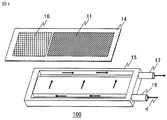
- FIG. 1 is an exploded perspective view showing a heat sink according to Embodiment 1 of the present invention
- FIG. 2 is a plan view of a base as seen from a surface on which fins are arranged.
- the heat sink 100 according to the first embodiment includes a surface 10 on which a heat generating element having a low heat generation density is installed, a surface 11 on which a heat generating element having a high heat generation density is installed, and a heat generation having a low heat generation density.
- the refrigerant enters the space between the jacket 15 and the base 14 through the refrigerant inlet portion 16, as indicated by the arrow a in FIG.
- the refrigerant exchanges heat with the first radiating fins 12 and the second radiating fins 13 that receive heat from the heating elements, and the heating elements are cooled through the first radiating fins 12 and the second radiating fins 13.
- the refrigerant that has received heat through heat exchange with the first and second radiating fins 12 and 13 is directly discharged to the outside of the heat sink 100 through the refrigerant outlet portion 17.
- the refrigerant may be liquid, gas, or gas-liquid mixture.
- FIG. 3 is an enlarged view of the first heat dissipating fin 12 having a shape in which a plurality of rows of meandering grooves zigzag with a narrow pitch are arranged.
- the refrigerant that has flowed into the first radiating fin 12 flows into a short flow path 18 that is parallel to the flow direction of the refrigerant, as shown by the arrow b.
- the refrigerant collides with the wall of the flow path, changes the flow direction by 90 °, and flows into the long flow path 19 perpendicular to the flow direction of the refrigerant.
- the refrigerant collides with the wall, passes through the short flow paths 18 and the long flow paths 19 alternately while changing the flow direction by 90 °, and is discharged from the first heat radiation fins 12.
- the refrigerant that passes through the pin-shaped second heat radiation fins 13 that are adjacent to the first heat radiation fins 12 having a shape in which a plurality of rows of grooves meandering in a narrow pitch zigzag are arranged, and arranged in parallel to the flow of the refrigerant.
- the first heat dissipating fin 12 has been described with respect to a shape in which a plurality of crank-shaped meandering grooves that change the direction of refrigerant flow by 90 ° are arranged. It is good also as a shape.
- the refrigerant flow rate per unit cross-sectional area in the refrigerant flow direction is the second radiating fin 13. Will be more. Therefore, the flow rate of the refrigerant just below the surface 11 on which the heat generating element having a high heat generation density is increased, and the heat sink 100 provides high cooling performance for the heat generating element having a high heat generation density. On the other hand, it provides low cooling performance and saves energy for circulating the refrigerant rather than flowing a large flow rate of refrigerant uniformly over the heat sink.
- FIG. 4 is a schematic diagram of the base viewed from the surface on which the heat dissipating fins of the heat sink 200 according to Embodiment 2 are arranged.
- the base 14 is arranged in parallel with a first radiating fin 12 having a shape in which a plurality of rows of grooves meandering in a narrow pitch zigzag having a large fluid resistance are arranged, and a pin-shaped second radiating fin 13 having a small fluid resistance.
- a small flow rate of refrigerant flows through the first radiating fin 12 having a large fluid resistance, and a large amount of refrigerant flows through the second radiating fin 13 having a small fluid resistance.
- the second heat radiation fin 13 is larger than the fin 12.
- the width W1 of the fin region in the direction perpendicular to the refrigerant flow direction of the second heat radiation fin 13 having a small fluid resistance is perpendicular to the refrigerant flow direction of the first heat radiation fin 12 having a large fluid resistance.
- the width W2 of the fin region in a certain direction is significantly smaller, the second heat radiation fin 13 having a small fluid resistance increases the fluid resistance due to a reduction in the cross-sectional area. 2
- the refrigerant flow rate of the first heat radiation fin 12 having a larger fluid resistance than the refrigerant flow rate of the heat radiation fin 13 becomes larger, which may cause a problem that the cooling performance of the heat generating element having a high heat generation density is insufficient.
- the above problem is likely to occur when the width W1 is extremely narrower than the width W2 due to layout.
- the cooling performance and pressure loss characteristics of the radiating fin are appropriately adjusted by the following method.
- the subscript of the second heat dissipating fin 13 having a small fluid resistance is 1
- the subscript of the first heat dissipating fin 12 having a large fluid resistance is 2
- h is a heat transfer coefficient as an index of cooling performance
- P is a pressure loss
- U is a pressure loss.
- FIG. 5 is a perspective view of the jacket of the heat sink 300 according to the third embodiment
- FIG. 6 is a cross-sectional view taken along line AA in FIG. 5
- FIG. 7 is an enlarged view of a portion B in FIG. .
- the fluid resistance in the gap is extremely small, and thus a large amount of refrigerant flows through the gap. Since the refrigerant flowing in the gap does not contribute to heat dissipation, the cooling performance is deteriorated.
- the heat sink 300 fills the gap between the first radiating fin 12 and the second radiating fin 13 when the projecting wall 50 is assembled to the jacket 15 and the jacket 15 and the base 14 are assembled. Further, the gap between the wall 50 and the first radiation fin 12 and the gap between the wall 50 and the second radiation fin 13 are the gap between the fins of the first radiation fin 12 or the second radiation fin 13. By making the gap smaller than the smaller one of the gaps between the fins, the fluid resistance of the gap between the wall 50 and the first radiating fin 12 or between the wall 50 and the second radiating fin 13 is increased. It is possible to prevent the gap from flowing through and to suppress a decrease in cooling performance.
- FIG. 8 is a plan view of the base as seen from the surface on which the heat dissipating fins of the heat sink according to the fourth embodiment are arranged, and FIG.
- a protrusion 90 in which a part of the radiating fin 13 is embedded is provided.
- the fluid resistance of the gap between the protrusion 90 and the adjacent second radiation fin 13 becomes substantially equal to the fluid resistance of the second radiation fin 13 itself. It is possible to prevent a large amount of refrigerant from flowing through the gap between the first radiating fin 12 and the second radiating fin 13, and to suppress a decrease in cooling performance.
- Embodiment 5 FIG. Next, a heat sink according to Embodiment 5 of the present invention will be described.
- the cross-sectional shape of the pin-shaped second radiating fin is a regular hexagon, square, or equilateral triangle (not shown), and the sides of the regular hexagon, square, or equilateral triangle are mutually connected. The distances between the sides facing each other and being spaced apart from each other are equally arranged.
- the pin-shaped second radiating fin has a higher cooling performance as the surface area per unit base area is larger.
- the side surfaces of the second heat dissipating fins may be opposed to each other, and the distances between the opposed sides may be equally spaced from each other.
- n-sided shape inscribed in a circle with the same radius is known to have the longest side length in the regular n-sided shape. It has been mathematically proved that there are only three types of regular polygons: regular triangles, squares, and regular hexagons.
- the cross-sectional shape of the pin-shaped second radiating fin is a regular hexagon, a square, or a regular triangle, and the cross-sectional sides are opposed to each other, and the distance between the sides that are spaced apart from each other is equal.
- the cooling performance of the second radiation fins can be particularly enhanced.
- the refrigerant on the side surface of the fin can be agitated to improve the cooling performance.
Landscapes
- Engineering & Computer Science (AREA)
- Physics & Mathematics (AREA)
- Thermal Sciences (AREA)
- Mechanical Engineering (AREA)
- General Engineering & Computer Science (AREA)
- Microelectronics & Electronic Packaging (AREA)
- Cooling Or The Like Of Semiconductors Or Solid State Devices (AREA)
- Cooling Or The Like Of Electrical Apparatus (AREA)
Abstract
高冷却性能を必要とする領域には流体抵抗の小さなピン形状の第1放熱フィン(12)を配置し、低冷却性能で良い領域においては、流体抵抗の大きな狭ピッチのジグザグに蛇行した溝を複数列並べた形状の第2放熱フィン(13)を配置する。更に、第1放熱フィン(12)と第2放熱フィン(13)を冷媒の流れ方向に対して並列に設置する。
Description
この発明は、例えば発熱素子を冷却するヒートシンクに関するものである。
パワー半導体のSiC(Silicon carbide)チップは高コストのため、チップのサイズを縮小する、所謂、チップシュリンクが必要不可欠となっており、その結果、発熱密度が増大し高温になることから、高熱伝達率を有するヒートシンクが求められている。
一方で、発熱密度が高いSiCと一緒に、発熱密度の低い部品が同一ヒートシンク上に配置される場合がある。
一方で、発熱密度が高いSiCと一緒に、発熱密度の低い部品が同一ヒートシンク上に配置される場合がある。
発熱密度の低い部品は低冷却性能であっても十分に冷却されるにもかかわらず、ヒートシンク全体に一様な流量で冷媒を流すと、低冷却性能で良い領域に対してはオーバースペックな放熱性能となり、冷却水を循環させるためのエネルギーが余分に消費されてしまう問題がある。そこで、低冷却性能で良い領域には小流量の冷媒を流し、高冷却性能を必要とする領域には大流量の冷媒を流すように流量を調整することが冷媒を循環させるための消費エネルギーの節約になり望ましい。
ヒートシンク内で冷媒の流量を調整する方法としては、例えば特許第5605438号公報(特許文献1)に、直径の異なるピンフィンを配置して、大流量の冷媒を流す領域の流体抵抗を小さくし、小流量の冷媒を流す領域の流体抵抗を大きくする方法が提案されている。
前記特許文献1に開示された方法では、冷却器の流路内に存在するピンフィンの直径を変えて配置することにより流路断面積を調整し、局所領域の流体抵抗を変化させて流量を調整している。しかしながら、上述のような従来の方法では、同一ヒートシンク上で、例えば単位断面積当たりの流量に2倍以上の差をつけるなど、極端な流量差をつけることができない問題があった。小流量の冷媒を流す領域に壁や絞りなどの障害物を設けて流体抵抗を増やせば大きな流量差をつけることも可能であるが、ヒートシンクの圧力損失を増加させることになり、消費エネルギーが増加してしまう問題があった。
この発明は、かかる問題点を解決することを課題とするものであって、同一ヒートシンク上で流量が小さい領域と大きい領域を設けることにより、発熱密度の大きな部品に対する冷却性能を大きくし、発熱密度の小さな部品に対する冷却性能を小さくしつつ、圧力損失の増加を抑制することができるヒートシンクを得ることを目的とする。
この発明に係るヒートシンクは、ベースに複数の放熱フィンを設けたヒートシンクであって、前記放熱フィンは、ピン形状の第1放熱フィンと狭ピッチの蛇行した溝を複数列並べた形状の第2放熱フィンとを備えて構成され、前記第1放熱フィンと前記第の放熱フィンは、前記ベースの同一平面上に、冷媒の流れ方向に対して並列に配置されていることを特徴とする。
この発明に係るヒートシンクによれば、狭ピッチの蛇行した溝を複数列並べた形状の第2放熱フィンに流入した冷媒は溝の壁に衝突して流れ方向を転換することを繰り返すため、流体抵抗が非常に大きく単位断面積当たりの冷媒の流入量は小さくなる。一方で、ピン形状の第1放熱フィンの流体抵抗は小さいので、第1放熱フィンの単位断面積当たりの冷媒の流入量は大きくなる。更に、第1放熱フィンと第2放熱フィンを冷媒の流れに対して並列に配置することで、合計圧力損失を抑制することが可能になる。
この発明の上記以外の目的、特徴、観点および効果は、図面を参照する以下のこの発明の詳細な説明から、さらに明らかになるであろう。
この発明の上記以外の目的、特徴、観点および効果は、図面を参照する以下のこの発明の詳細な説明から、さらに明らかになるであろう。
以下、この発明に係るヒートシンクの実施の形態について図に基づいて説明する。なお、各図において同一または相当部分については同一符号を付して説明する。
実施の形態1.
図1は、この発明の実施の形態1に係るヒートシンクを示す分解斜視図であり、図2はフィンが配置された面から見たベースの平面図である。
図1及び図2において、実施の形態1に係るヒートシンク100は、発熱密度が低い発熱素子が設置された面10と、発熱密度が高い発熱素子が設置された面11と、発熱密度が低い発熱素子が設置された面10の裏面に設けられた狭ピッチのジグザグに蛇行した溝を複数列並べた形状の第1放熱フィン12と、発熱密度が高い発熱素子が設置された面11の裏面に設けられたピン形状の第2放熱フィン13を有するベース14と、ベース14を収納したジャケット15と、このジャケット15の対向した側面にそれぞれ設けられた冷媒入口部16及び冷媒出口部17と、を備えて構成されている。
このヒートシンク100では、冷媒は図1の矢印イに示すように、冷媒入口部16を通ってジャケット15とベース14との間の空間に入る。この空間内では、冷媒は発熱素子から受熱した第1放熱フィン12及び第2放熱フィン13と熱交換し、第1放熱フィン12及び第2放熱フィン13を通じて発熱素子は冷却される。第1放熱フィン12及び第2放熱フィン13との熱交換により受熱した冷媒は、そのまま冷媒出口部17を通じてヒートシンク100の外部に排出される。なお、冷媒は液体、気体、気液混合体を問わない。
図3は、狭ピッチのジグザグに蛇行した溝を複数列並べた形状の第1放熱フィン12の拡大図である。図3において、第1放熱フィン12に流入した冷媒は矢印ロに示す様に、冷媒の流通方向と平行な短い流路18に流入する。その後、冷媒は流路の壁に衝突し、流れ方向を90°変え、冷媒の流通方向と垂直な長い流路19に流入する。冷媒は、その後、壁に衝突し、流れ方向を90°変えながら、短い流路18と長い流路19を交互に通過して第1放熱フィン12から排出される。
このように、冷媒は流路の壁に衝突し、流れの方向を90°変えるという事を繰り返しながら流れるため、流体抵抗は非常に大きくなる。
一方、狭ピッチのジグザグに蛇行した溝を複数列並べた形状の第1放熱フィン12に隣接し、冷媒の流れに対して並列に配置されているピン形状の第2放熱フィン13を通過する冷媒は、第1放熱フィン12を通過するときの様に急激な流れ方向変化が無く、冷媒流通方向の単位断面積当たりの流路断面積が大きいため、流体抵抗は小さい。
なお、前記においては、第1放熱フィン12が、冷媒の流れる方向を90°変えるクランク形の蛇行した溝を複数列並べた形状について説明したが、例えばV形に蛇行した溝を複数列並べた形状としてもよい。
以上の様に、流体抵抗の大きな第1放熱フィン12と流体抵抗の小さな第2放熱フィン13が並列に配置されている場合、冷媒流通方向の単位断面積当たりの冷媒流量は第2放熱フィン13の方が多くなる。よって、発熱密度が高い発熱素子が設置された面11の直下の冷媒流量が多くなり、ヒートシンク100は発熱密度が高い発熱素子に対しては高い冷却性能を提供し、発熱密度が低い発熱素子に対しては低い冷却性能を提供し、ヒートシンク全体に均一に大流量の冷媒を流すよりも冷媒を循環させるためのエネルギーを節約できる。
実施の形態2.
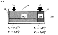
次に、この発明の実施の形態2に係るヒートシンクについて説明する。図4は、実施の形態2に係るヒートシンク200の放熱フィンが配置された面から見たベースの模式図である。
ベース14には、流体抵抗の大きな狭ピッチのジグザグに蛇行した溝を複数列並べた形状の第1放熱フィン12と、流体抵抗の小さなピン形状の第2放熱フィン13とが並列に配置されており、一般的には、流体抵抗の大きな第1放熱フィン12には小流量の冷媒が流れ、流体抵抗の小さな第2放熱フィン13には大流量の冷媒が流れるため、冷却性能は第1放熱フィン12よりも第2放熱フィン13の方が大きくなる。
次に、この発明の実施の形態2に係るヒートシンクについて説明する。図4は、実施の形態2に係るヒートシンク200の放熱フィンが配置された面から見たベースの模式図である。
ベース14には、流体抵抗の大きな狭ピッチのジグザグに蛇行した溝を複数列並べた形状の第1放熱フィン12と、流体抵抗の小さなピン形状の第2放熱フィン13とが並列に配置されており、一般的には、流体抵抗の大きな第1放熱フィン12には小流量の冷媒が流れ、流体抵抗の小さな第2放熱フィン13には大流量の冷媒が流れるため、冷却性能は第1放熱フィン12よりも第2放熱フィン13の方が大きくなる。
しかしながら図4に示すように、流体抵抗の小さな第2放熱フィン13の冷媒の流通方向と垂直な方向のフィン領域の幅W1が、流体抵抗の大きな第1放熱フィン12の冷媒の流通方向と垂直な方向のフィン領域の幅W2よりも著しく小さくなると、流体抵抗の小さな第2放熱フィン13は、断面積が小さくなることにより流体抵抗が増加するため、冷媒流量が逆転し、流体抵抗の小さな第2放熱フィン13の冷媒流量よりも流体抵抗の大きな第1放熱フィン12の冷媒流量の方が大きくなり、発熱密度が高い発熱素子の冷却性能が不足してしまう問題が発生する場合がある。例えば、レイアウトの都合上、幅W1が幅W2よりも極端に狭くなる場合などでは、上記問題が発生しやすい。
上記問題を回避するため、実施の形態2のヒートシンクでは、次に示す方法で放熱フィンの冷却性能と圧力損失の特性を適切に調整する。
流体抵抗の小さな第2放熱フィン13の添え字を1、流体抵抗の大きな第1放熱フィン12の添え字を2とし、hを冷却性能の指標である熱伝達率、Pを圧力損失、Uを前面流速、γ、δ、m、nをフィン形状で決まる定数と置くと、それぞれの領域の熱伝達率hと、圧力損失Pは、それぞれ次式(1)~(4)で表わすことができる。
h1=γ1U1m1・・・(1)
P1=δ1U1n1・・・(2)
h2=γ2U2m2・・・(3)
P2=δ2U2n2・・・(4)
ここで、冷媒は放熱フィンに対して並列に流されているため、P1=P2が成り立つ。
(2)式と(4)式より、
δ1U1n1=δ2U2n2
故に、U2={(δ1/δ2)U1n1}1/n2・・・(5)
となり、(5)式が得られる。この(5)式を(3)式に代入、整理すると
h2=γ2{(δ1/δ2)U1n1}m2/n2・・・(6)
となる。
ここで、第1放熱フィン12の冷却性能よりも第2放熱フィン13の冷却性能が大きくするには、h2<h1とすればよく、h2<h1を(6)式に代入、整理すると
{(γ2δ1)/(γ1δ2)}m2/n2<U1(m1n2-m2n1)/n2・・・(7)
となる。
ここで、一般的に熱伝達率はおおよそ流速の0.5乗に比例し、圧損はおおよそ流速の2乗に比例することが知られており、簡単のためここではm1=m2=0.5、n1=n2=2と置き(7)式に代入、整理して
(δ1/δ2)0.25<γ1/γ2・・・(8)
が得られる。第1放熱フィン12と第2放熱フィン13の特性を(8)式を満たす様に設定することにより、確実に第2放熱フィン13の冷却性能を第1放熱フィン12の冷却性能より大きくすることができる。
{(γ2δ1)/(γ1δ2)}m2/n2<U1(m1n2-m2n1)/n2・・・(7)
となる。
ここで、一般的に熱伝達率はおおよそ流速の0.5乗に比例し、圧損はおおよそ流速の2乗に比例することが知られており、簡単のためここではm1=m2=0.5、n1=n2=2と置き(7)式に代入、整理して
(δ1/δ2)0.25<γ1/γ2・・・(8)
が得られる。第1放熱フィン12と第2放熱フィン13の特性を(8)式を満たす様に設定することにより、確実に第2放熱フィン13の冷却性能を第1放熱フィン12の冷却性能より大きくすることができる。
実施の形態3.
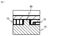
次に、この発明の実施の形態3に係るヒートシンクについて説明する。図5は、実施の形態3に係るヒートシンク300のジャケットの斜視図、図6は図5のA-A線に沿う矢視断面図、図7は図6のB部の拡大図を示している。
狭ピッチのジグザグに蛇行した溝を複数列並べた形状の第1放熱フィン12とピン形状の第2放熱フィン13を例えばダイカストや鍛造等で製造する場合、離型性や型寿命向上の観点から第1放熱フィン12と第2放熱フィン13の間に隙間を設けた方が良い。
次に、この発明の実施の形態3に係るヒートシンクについて説明する。図5は、実施の形態3に係るヒートシンク300のジャケットの斜視図、図6は図5のA-A線に沿う矢視断面図、図7は図6のB部の拡大図を示している。
狭ピッチのジグザグに蛇行した溝を複数列並べた形状の第1放熱フィン12とピン形状の第2放熱フィン13を例えばダイカストや鍛造等で製造する場合、離型性や型寿命向上の観点から第1放熱フィン12と第2放熱フィン13の間に隙間を設けた方が良い。
しかしながら、第1放熱フィン12と第2放熱フィン13の間に隙間を設けると、隙間の流体抵抗は極端に小さいため、隙間に多くの冷媒が流れてしまう。隙間に流れた冷媒は、放熱には寄与しないため、冷却性能は低下してしまう。
そこで、実施の形態3に係るヒートシンク300は、ジャケット15に対し突起状の壁50を、ジャケット15とベース14を組み立てた際に、第1放熱フィン12と第2放熱フィン13の隙間を埋めるような位置に設け、更に、壁50と第1放熱フィン12との隙間、及び壁50と第2放熱フィン13との隙間は、第1放熱フィン12のフィン同士の隙間、もしくは第2放熱フィン13のフィン同士の隙間のうちの何れか小さい方の隙間より、小さくすることにより、壁50と第1放熱フィン12、あるいは壁50と第2放熱フィン13との隙間の流体抵抗を上げ、冷媒が隙間を流れることを防ぎ、冷却性能の低下を抑制することができる。
実施の形態4.
次に、この発明の実施の形態4に係るヒートシンクについて説明する。図8は、実施の形態4に係るヒートシンクの放熱フィンが配置された面から見たベースの平面図、図9は図8のC部の拡大図である。
実施の形態4に係るヒートシンク400では、第1放熱フィン12と第2放熱フィン13の間の隙間に多くの冷媒が流れてしまうことを防ぐため、第1放熱フィン12側の端部に第2放熱フィン13の一部を埋め込んだ突起90を設けた。
次に、この発明の実施の形態4に係るヒートシンクについて説明する。図8は、実施の形態4に係るヒートシンクの放熱フィンが配置された面から見たベースの平面図、図9は図8のC部の拡大図である。
実施の形態4に係るヒートシンク400では、第1放熱フィン12と第2放熱フィン13の間の隙間に多くの冷媒が流れてしまうことを防ぐため、第1放熱フィン12側の端部に第2放熱フィン13の一部を埋め込んだ突起90を設けた。
実施の形態4に係るヒートシンク400は、突起90を設けることにより、突起90と隣接する第2放熱フィン13との隙間の流体抵抗が第2放熱フィン13そのものの流体抵抗とほぼ等しくなるため、第1放熱フィン12と第2放熱フィン13の隙間に多くの冷媒が流れることを防ぎ、冷却性能の低下を抑制することができる。
実施の形態5.
次に、この発明の実施の形態5に係るヒートシンクについて説明する。実施の形態5のヒートシンクは、ピン形状の第2放熱フィンの断面形状が正六角形、もしくは正方形、もしくは正三角形(図示せず)であり、前記正六角形、もしくは正方形、もしくは正三角形の辺が互いに全面対向し、かつ、それぞれ互いに離間して対向した前記辺間距離が等しく配置されている。
次に、この発明の実施の形態5に係るヒートシンクについて説明する。実施の形態5のヒートシンクは、ピン形状の第2放熱フィンの断面形状が正六角形、もしくは正方形、もしくは正三角形(図示せず)であり、前記正六角形、もしくは正方形、もしくは正三角形の辺が互いに全面対向し、かつ、それぞれ互いに離間して対向した前記辺間距離が等しく配置されている。
ピン形状の第2放熱フィンは、単位ベース面積当たりの表面積が大きい程、冷却性能が高い。単位ベース面積当たりの表面積を大きくするには、第2放熱フィンの側面を互いに全面対向させ、かつ、それぞれ互いに離間して対向した辺間距離が等しく配置するようにすればよい。
一般的に同一半径の円に内接するn角形では、正n角形が最も辺の長さが長い事が知られており、各互いに離間して対向した辺と辺の距離が等しく配置されるのは、正多角形の中でも正三角形、正方形、正六角形の3種類のみであることが数学的に証明されている。
上記により、ピン形状の第2放熱フィンの断面形状が正六角形、もしくは正方形、もしくは正三角形であり、断面形状の辺が互いに全面対向し、かつ、それぞれ互いに離間して対向した辺間距離が等しく配置された放熱フィンを第2放熱フィンとすることで、第2放熱フィンの冷却性能を特に高くすることができる。更に、第2放熱フィンの側面に凹凸を設けることにより、フィン側面の冷媒を撹拌し、冷却性能を高めることができる。
以上、この発明の実施の形態1から実施の形態5に係るヒートシンクについて説明したが、この発明は、その発明の範囲内において、各実施の形態を組み合わせたり、各実施の形態を適宜、変形、省略することが可能である。
10 発熱密度が低い発熱素子が設置された面、11 発熱密度が高い発熱素子が設置された面、12 第1放熱フィン、13 第2放熱フィン、14 ベース、15 ジャケット、16 冷媒入口部、17 冷媒出口部、18 短い流路、19 長い流路、50 壁、90 突起、100、200、300、400 ヒートシンク。
Claims (8)
- ベースに複数の放熱フィンを設けたヒートシンクにおいて、
前記放熱フィンは、ピン形状の第1放熱フィンと狭ピッチの蛇行した溝を複数列並べた形状の第2放熱フィンとを備えて構成され、
前記第1放熱フィンと前記第2放熱フィンは、前記ベースの同一平面上に、冷媒の流れ方向に対して並列に配置されていることを特徴とするヒートシンク。 - 前記第1放熱フィンを表す添え字を1、前記第2放熱フィンを表す添え字を2と置き、hを熱伝達率、Pをフィンの圧力損失、Uをフィン領域に冷媒が流入する直前の流速、γ、δ、m、nをフィン形状で一意に決まる定数と置いたとき、h1=γ1U1m1、P1=δ1U1n1、h2=γ2U2m2、P2=δ2U2n2で表されるδ1、δ2、γ1、γ2が(δ1/δ2)0.25<γ1/γ2を満たすことを特徴とする請求項1に記載のヒートシンク。
- 前記ヒートシンクのジャケットには、前記第1放熱フィンと、前記第2放熱フィンとの隙間に壁が設けられており、前記壁と前記第1放熱フィンとの隙間、及び前記壁と前記第2放熱フィンとの隙間は、前記第1放熱フィンのフィン同士の隙間、もしくは第2放熱フィンのフィン同士の隙間のうちの何れか小さい方の隙間より、小さくしたことを特徴とする請求項1又は2に記載のヒートシンク。
- 前記第2放熱フィンの前記第1放熱フィンが隣接する側の壁に、前記第1放熱フィンの一部を形成したことを特徴とする請求項1又は2に記載のヒートシンク。
- 前記第1放熱フィンは、断面形状が正六角形であり、前記正六角形の辺が互いに全面対向し、かつ、それぞれ互いに離間して対向した辺間距離が等しく配置されていることを特徴とする請求項1又は2に記載のヒートシンク。
- 前記第1放熱フィンは、断面形状が正方形であり、前記正方形の辺が互いに全面対向し、かつ、それぞれ互いに離間して対向した辺間距離が等しく配置されていることを特徴とする請求項1又は2に記載のヒートシンク。
- 前記第1放熱フィンは、断面形状が正三角形であり、前記正三角形の辺が互いに全面対向し、かつ、それぞれ互いに離間して対向した辺間距離が等しく配置されていることを特徴とする請求項1又は2に記載のヒートシンク。
- 前記第1放熱フィンの側面に凹凸を設けたことを特徴とする請求項6又は7に記載のヒートシンク。
Priority Applications (3)
| Application Number | Priority Date | Filing Date | Title |
|---|---|---|---|
| EP17894434.4A EP3576509B1 (en) | 2017-01-24 | 2017-03-17 | Heat sink |
| CN201780084014.8A CN110226365B (zh) | 2017-01-24 | 2017-03-17 | 散热器 |
| US16/466,397 US11085702B2 (en) | 2017-01-24 | 2017-03-17 | Heat sink |
Applications Claiming Priority (2)
| Application Number | Priority Date | Filing Date | Title |
|---|---|---|---|
| JP2017009994A JP6462737B2 (ja) | 2017-01-24 | 2017-01-24 | ヒートシンク |
| JP2017-009994 | 2017-01-24 |
Publications (1)
| Publication Number | Publication Date |
|---|---|
| WO2018138936A1 true WO2018138936A1 (ja) | 2018-08-02 |
Family
ID=62979433
Family Applications (1)
| Application Number | Title | Priority Date | Filing Date |
|---|---|---|---|
| PCT/JP2017/010978 Ceased WO2018138936A1 (ja) | 2017-01-24 | 2017-03-17 | ヒートシンク |
Country Status (5)
| Country | Link |
|---|---|
| US (1) | US11085702B2 (ja) |
| EP (1) | EP3576509B1 (ja) |
| JP (1) | JP6462737B2 (ja) |
| CN (1) | CN110226365B (ja) |
| WO (1) | WO2018138936A1 (ja) |
Cited By (3)
| Publication number | Priority date | Publication date | Assignee | Title |
|---|---|---|---|---|
| CN111417293A (zh) * | 2020-05-11 | 2020-07-14 | 无锡金鑫集团股份有限公司 | 散热片 |
| DE102019210192A1 (de) * | 2019-07-10 | 2020-08-20 | Siemens Aktiengesellschaft | Kühlung von elektrischen Bauelementen |
| WO2020169421A3 (de) * | 2019-02-22 | 2020-11-12 | Volkswagen Aktiengesellschaft | ANORDNUNG ZUM GLEICHMÄßIGEN KÜHLEN VON BAUTEILEN UND KRAFTFAHRZEUG MIT ZUMINDEST EINER ANORDNUNG |
Families Citing this family (12)
| Publication number | Priority date | Publication date | Assignee | Title |
|---|---|---|---|---|
| US10809017B2 (en) * | 2016-05-10 | 2020-10-20 | Mitsubishi Electric Corporation | Heat sink with projection and recess shaped fins |
| DE102018217652A1 (de) * | 2018-10-15 | 2020-04-16 | Danfoss Silicon Power Gmbh | Strömungsverteiler zum Kühlen einer elektrischen Baugruppe, ein Halbleitermodul mit einem derartigen Strömungsverteiler und ein Verfahren zu dessen Herstellung |
| JP7407577B2 (ja) * | 2019-12-04 | 2024-01-04 | 三菱電機株式会社 | ヒートシンク |
| CN111415915B (zh) * | 2020-04-30 | 2022-07-12 | 西安交通大学 | 一种微通道散热器散热结构 |
| CN114980645A (zh) * | 2021-02-23 | 2022-08-30 | 日本电产艾莱希斯株式会社 | 电子部件模块 |
| JP2023011389A (ja) * | 2021-07-12 | 2023-01-24 | 日本電産株式会社 | 放熱部材 |
| JP2023011392A (ja) * | 2021-07-12 | 2023-01-24 | 日本電産株式会社 | 放熱部材 |
| DE102021210934A1 (de) * | 2021-09-30 | 2023-03-30 | Robert Bosch Gesellschaft mit beschränkter Haftung | Kühler zum Kühlen einer Leistungselektronik |
| DE102021211059A1 (de) * | 2021-10-01 | 2023-04-06 | Robert Bosch Gesellschaft mit beschränkter Haftung | Kühler zum Kühlen einer Leistungselektronik |
| CN115467398A (zh) | 2022-08-23 | 2022-12-13 | 珠海大励厨卫科技有限公司 | 一种带拼接支架的水槽 |
| US11965702B1 (en) * | 2022-10-21 | 2024-04-23 | Amulaire Thermal Technology, Inc. | Low pressure drop automotive liquid-cooling heat dissipation plate and enclosed automotive liquid-cooling cooler having the same |
| CN115831893A (zh) * | 2022-12-06 | 2023-03-21 | 扬州国扬电子有限公司 | 一种高效散热电力电子模块散热装置 |
Citations (8)
| Publication number | Priority date | Publication date | Assignee | Title |
|---|---|---|---|---|
| JPS565438B2 (ja) | 1976-03-31 | 1981-02-04 | ||
| JP2005020881A (ja) * | 2003-06-25 | 2005-01-20 | Aisin Aw Co Ltd | 駆動装置 |
| JP2008171840A (ja) * | 2007-01-05 | 2008-07-24 | T Rad Co Ltd | 液冷ヒートシンクおよびその設計方法 |
| JP2010203694A (ja) * | 2009-03-04 | 2010-09-16 | Showa Denko Kk | 液冷式冷却装置 |
| JP2012044140A (ja) * | 2010-07-23 | 2012-03-01 | Fuji Electric Co Ltd | 半導体装置 |
| WO2012114475A1 (ja) * | 2011-02-23 | 2012-08-30 | トヨタ自動車株式会社 | 冷却器 |
| JP2012199421A (ja) * | 2011-03-22 | 2012-10-18 | Mitsubishi Electric Corp | プレート型冷却器及びその製造方法 |
| WO2017005462A1 (de) * | 2015-07-08 | 2017-01-12 | Robert Bosch Gmbh | Leistungshalbleiterbauteil mit einer kühlvorrichtung |
Family Cites Families (14)
| Publication number | Priority date | Publication date | Assignee | Title |
|---|---|---|---|---|
| US4995450A (en) * | 1989-08-18 | 1991-02-26 | G.P. Industries, Inc. | Heat pipe |
| US5168348A (en) * | 1991-07-15 | 1992-12-01 | International Business Machines Corporation | Impingment cooled compliant heat sink |
| US6140571A (en) * | 1992-08-06 | 2000-10-31 | Pfu Limited | Heat-generating element cooling device |
| JP3864916B2 (ja) * | 2002-08-29 | 2007-01-10 | 株式会社デンソー | 熱交換器 |
| US7497013B2 (en) * | 2005-04-15 | 2009-03-03 | R-Theta Thermal Solutions Inc. | Method and apparatus for coupling fins in a high-fin density heatsink to dual heat-dissipating base plates |
| JP4928749B2 (ja) * | 2005-06-30 | 2012-05-09 | 株式会社東芝 | 冷却装置 |
| JP2008210007A (ja) | 2007-02-23 | 2008-09-11 | Alps Electric Co Ltd | 液冷システム |
| CN102549743B (zh) * | 2009-08-10 | 2014-12-24 | 富士电机株式会社 | 半导体模块和冷却单元 |
| JP5162538B2 (ja) | 2009-08-11 | 2013-03-13 | 昭和電工株式会社 | 液冷式冷却装置 |
| US20120211214A1 (en) * | 2010-12-09 | 2012-08-23 | Panasonic Avionics Corporation | Heatsink Device and Method |
| CN103314436A (zh) | 2011-01-12 | 2013-09-18 | 丰田自动车株式会社 | 冷却器 |
| CN104911878B (zh) * | 2014-03-14 | 2018-12-25 | 青岛海尔滚筒洗衣机有限公司 | 一种叠加式热交换器 |
| WO2016194158A1 (ja) * | 2015-06-03 | 2016-12-08 | 三菱電機株式会社 | 液冷冷却器、及び液冷冷却器に於ける放熱フィンの製造方法 |
| CN105318767A (zh) * | 2015-08-15 | 2016-02-10 | 何家密 | 主动式热交换以及其应用 |
-
2017
- 2017-01-24 JP JP2017009994A patent/JP6462737B2/ja active Active
- 2017-03-17 US US16/466,397 patent/US11085702B2/en active Active
- 2017-03-17 WO PCT/JP2017/010978 patent/WO2018138936A1/ja not_active Ceased
- 2017-03-17 EP EP17894434.4A patent/EP3576509B1/en active Active
- 2017-03-17 CN CN201780084014.8A patent/CN110226365B/zh active Active
Patent Citations (8)
| Publication number | Priority date | Publication date | Assignee | Title |
|---|---|---|---|---|
| JPS565438B2 (ja) | 1976-03-31 | 1981-02-04 | ||
| JP2005020881A (ja) * | 2003-06-25 | 2005-01-20 | Aisin Aw Co Ltd | 駆動装置 |
| JP2008171840A (ja) * | 2007-01-05 | 2008-07-24 | T Rad Co Ltd | 液冷ヒートシンクおよびその設計方法 |
| JP2010203694A (ja) * | 2009-03-04 | 2010-09-16 | Showa Denko Kk | 液冷式冷却装置 |
| JP2012044140A (ja) * | 2010-07-23 | 2012-03-01 | Fuji Electric Co Ltd | 半導体装置 |
| WO2012114475A1 (ja) * | 2011-02-23 | 2012-08-30 | トヨタ自動車株式会社 | 冷却器 |
| JP2012199421A (ja) * | 2011-03-22 | 2012-10-18 | Mitsubishi Electric Corp | プレート型冷却器及びその製造方法 |
| WO2017005462A1 (de) * | 2015-07-08 | 2017-01-12 | Robert Bosch Gmbh | Leistungshalbleiterbauteil mit einer kühlvorrichtung |
Non-Patent Citations (1)
| Title |
|---|
| See also references of EP3576509A4 |
Cited By (3)
| Publication number | Priority date | Publication date | Assignee | Title |
|---|---|---|---|---|
| WO2020169421A3 (de) * | 2019-02-22 | 2020-11-12 | Volkswagen Aktiengesellschaft | ANORDNUNG ZUM GLEICHMÄßIGEN KÜHLEN VON BAUTEILEN UND KRAFTFAHRZEUG MIT ZUMINDEST EINER ANORDNUNG |
| DE102019210192A1 (de) * | 2019-07-10 | 2020-08-20 | Siemens Aktiengesellschaft | Kühlung von elektrischen Bauelementen |
| CN111417293A (zh) * | 2020-05-11 | 2020-07-14 | 无锡金鑫集团股份有限公司 | 散热片 |
Also Published As
| Publication number | Publication date |
|---|---|
| JP2018120904A (ja) | 2018-08-02 |
| JP6462737B2 (ja) | 2019-01-30 |
| CN110226365B (zh) | 2021-03-23 |
| EP3576509B1 (en) | 2025-03-12 |
| US20190331428A1 (en) | 2019-10-31 |
| EP3576509A1 (en) | 2019-12-04 |
| EP3576509A4 (en) | 2020-01-22 |
| CN110226365A (zh) | 2019-09-10 |
| US11085702B2 (en) | 2021-08-10 |
Similar Documents
| Publication | Publication Date | Title |
|---|---|---|
| JP6462737B2 (ja) | ヒートシンク | |
| JP5523542B1 (ja) | 冷却装置 | |
| JP5605438B2 (ja) | 冷却器 | |
| CN107615479A (zh) | 液冷冷却器和液冷冷却器中的散热翅片的制造方法 | |
| JP2020145245A (ja) | ヒートシンク及びこれを備えた半導体モジュール | |
| WO2013118869A1 (ja) | 半導体冷却装置 | |
| US20120012284A1 (en) | heat sink with staggered heat exchange elements | |
| US20090272516A1 (en) | Method of Determining a Size of a Heat Exchanger for a Vehicle | |
| Li et al. | A novel microchannel heat sink with staggered inlet and outlet to improve base surface temperature uniformity | |
| JP7106013B2 (ja) | ヒートシンクおよび半導体モジュール | |
| JP5589647B2 (ja) | 冷却装置 | |
| JP5498135B2 (ja) | ヒートシンク | |
| CN119212321B (zh) | 一种带翅片冲击射流双层微通道热沉结构及其工作方法 | |
| JP2008300447A (ja) | 放熱装置 | |
| CN115084997B (zh) | 一种激光器冷却热沉装置及其半导体激光器 | |
| JP6874823B1 (ja) | 冷却構造及びヒートシンク | |
| JP2014033015A (ja) | 冷却器 | |
| JP6924787B2 (ja) | ヒートシンク及び熱交換器 | |
| US20250155203A1 (en) | Lanced offset heat exchange fin pack design | |
| JP2005123260A (ja) | 水冷式ヒートシンク | |
| JP2017069522A (ja) | コールドプレート | |
| JP2005166789A (ja) | 放熱器 | |
| WO2026003633A1 (en) | Fluid jet cooling device for electronic equipment | |
| CN120916382A (zh) | 一种具有周期性空腔的微通道散热板 | |
| CN120780121A (zh) | 一种均温针式散热器 |
Legal Events
| Date | Code | Title | Description |
|---|---|---|---|
| 121 | Ep: the epo has been informed by wipo that ep was designated in this application |
Ref document number: 17894434 Country of ref document: EP Kind code of ref document: A1 |
|
| NENP | Non-entry into the national phase |
Ref country code: DE |
|
| ENP | Entry into the national phase |
Ref document number: 2017894434 Country of ref document: EP Effective date: 20190826 |