WO2018139155A1 - Chaîne et transporteur à chaîne - Google Patents
Chaîne et transporteur à chaîne Download PDFInfo
- Publication number
- WO2018139155A1 WO2018139155A1 PCT/JP2017/046798 JP2017046798W WO2018139155A1 WO 2018139155 A1 WO2018139155 A1 WO 2018139155A1 JP 2017046798 W JP2017046798 W JP 2017046798W WO 2018139155 A1 WO2018139155 A1 WO 2018139155A1
- Authority
- WO
- WIPO (PCT)
- Prior art keywords
- pair
- chain
- roller
- path
- link plates
- Prior art date
- Legal status (The legal status is an assumption and is not a legal conclusion. Google has not performed a legal analysis and makes no representation as to the accuracy of the status listed.)
- Ceased
Links
Images


Classifications
-
- B—PERFORMING OPERATIONS; TRANSPORTING
- B65—CONVEYING; PACKING; STORING; HANDLING THIN OR FILAMENTARY MATERIAL
- B65G—TRANSPORT OR STORAGE DEVICES, e.g. CONVEYORS FOR LOADING OR TIPPING, SHOP CONVEYOR SYSTEMS OR PNEUMATIC TUBE CONVEYORS
- B65G17/00—Conveyors having an endless traction element, e.g. a chain, transmitting movement to a continuous or substantially-continuous load-carrying surface or to a series of individual load-carriers; Endless-chain conveyors in which the chains form the load-carrying surface
- B65G17/06—Conveyors having an endless traction element, e.g. a chain, transmitting movement to a continuous or substantially-continuous load-carrying surface or to a series of individual load-carriers; Endless-chain conveyors in which the chains form the load-carrying surface having a load-carrying surface formed by a series of interconnected, e.g. longitudinal, links, plates, or platforms
-
- F—MECHANICAL ENGINEERING; LIGHTING; HEATING; WEAPONS; BLASTING
- F16—ENGINEERING ELEMENTS AND UNITS; GENERAL MEASURES FOR PRODUCING AND MAINTAINING EFFECTIVE FUNCTIONING OF MACHINES OR INSTALLATIONS; THERMAL INSULATION IN GENERAL
- F16G—BELTS, CABLES, OR ROPES, PREDOMINANTLY USED FOR DRIVING PURPOSES; CHAINS; FITTINGS PREDOMINANTLY USED THEREFOR
- F16G13/00—Chains
- F16G13/02—Driving-chains
- F16G13/06—Driving-chains with links connected by parallel driving-pins with or without rollers so called open links
Definitions
- the present invention relates to a chain and a chain conveyor.
- a chain shown in Patent Document 1 is known as a chain used in a chain conveyor for transporting an object to be transported.
- Such a chain is formed in an endless shape, and has two rows of link plate rows including an inner link plate and an outer link plate.
- Each of these two link plate rows has a bendable structure in which inner link plates and outer link plates are alternately connected by pins.
- a roller is rotatably provided inside the two link plate rows.
- the roller is configured to mesh with the teeth of the drive sprocket and the driven sprocket.
- Guide rollers are rotatably supported by pins on both outer sides of the two rows of link plate rows.
- endless guide rails are provided so as to extend along the chain movement path. The guide roller is configured to roll on the guide rail.
- the chain as described above receives the load with a guide roller. For this reason, it is necessary to increase the outer diameter of the guide roller so that the chain can withstand a greater load. However, if the outer diameter of the guide roller is made too large, there is a problem that it becomes difficult to manufacture the chain because the interval between the adjacent guide rollers becomes narrow.
- An object of the present invention is to provide a chain and a chain conveyor that can be easily manufactured while ensuring load resistance.
- the chain includes a pair of inner link plates disposed opposite to each other, a cylindrical bush having both ends joined to the pair of inner link plates, and the bush.
- a pin that is rotatably inserted into the bush, a cylindrical first roller that is rotatable around the bush and engageable with the sprocket, and a pair of inner link plates that are sandwiched from the outside.
- the outer diameter of the second roller is set to be 70% or more and 90% or less of the chain pitch.
- the outer diameter of the second roller is set to be 70% or more and 90% or less of the chain pitch, while ensuring the interval between the second rollers adjacent in the longitudinal direction of the chain,
- the outer diameter of the second roller can be made larger. Therefore, the chain can be easily manufactured while ensuring the load resistance of the chain.
- the chain conveyor includes a linear first path portion, a linear second path portion disposed below the first path portion, the first path portion, An endless path having a curved third path section that connects the ends of the second path section, and a pair of endless chains configured to circulate along the endless path; A pair of guide rails that support the second roller of the pair of chains and guide the pair of chains along the endless path; and a mounting surface on which an object to be conveyed is mounted; A plurality of planar members that are coupled to the chain and circulate along the endless path together with the chain, two pairs of sprockets around which the pair of chains are wound in the third path portion, and two pairs of the above Sprocket And a driving unit for rotationally driving one of the.
- a chain having excellent load resistance can be easily manufactured.
- FIG. 4 is a side view of FIG. 3.
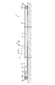
- the side surface schematic diagram which shows the guide rail and its periphery in a chain conveyor.
- the chain conveyor 11 is installed on the floor surface F, and is extended in parallel with the conveyance direction A (left direction in FIG. 1) of the to-be-conveyed object H.
- the chain conveyor 11 includes a linear first path portion 12, a linear second path portion 13 disposed below the first path portion 12, and ends of the first path portion 12 and the second path portion 13.
- An endless path 15 having two curved third path portions 14 a and 14 b that connect the sections to each other, and an endless transport unit 16 that circulates along the endless path 15 are provided.
- the transport unit 16 includes a pair of endless chains 20 and a plurality of planar members 22 each connecting the pair of chains 20 to each other.
- the planar member 22 has a rectangular plate shape and forms a placement surface 21 on which the transported object H is placed.
- one third path portion 14 a is located at the front end of the chain conveyor 11 in the transport direction A
- the other third path portion 14 b is the transport direction in the chain conveyor 11. It is located at the rear end of A.
- the chain conveyor 11 includes a pair of sprockets 23a around which the pair of chains 20 are wound in the third path portion 14a, a pair of sprockets 23b around which the pair of chains 20 are wound in the third path portion 14b, and two pairs of sprockets 23a. , 23b, and a drive unit 24 that rotationally drives a pair of sprockets 23a.
- the drive unit 24 is configured by, for example, a motor and a speed reducer.
- the sprockets 23a and 23b are constituted by involute sprockets, for example.
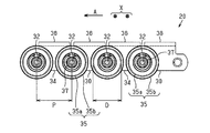
- each chain 20 includes a pair of inner link plates 30 and a pair of outer link plates 34 that are alternately connected by pins 32.
- the pair of outer link plates 34 are disposed so as to sandwich the pair of inner link plates 30 from the outside, and both end portions of the pins 32 are joined to the outer link plate so as not to rotate.
- the pair of inner link plates 30 are disposed opposite to each other in the width direction X orthogonal to the transport direction A.
- Two cylindrical bushes 31 are provided between the pair of inner link plates 30, and both ends of each bush 31 are joined to the inner link plate 30 so as not to rotate.
- the pin 32 is rotatably inserted into the bush 31.
- Each chain 20 further includes a cylindrical first roller 33 that is rotatably disposed around the bush 31. The first roller 33 can be engaged (engaged) with the sprockets 23a and 23b.
- a pin 32 protrudes outward in the width direction X from one of the pair of outer link plates 34.
- a cylindrical second roller 35 is provided at the protruding portion of the pin 32 so as to be rotatable about the axis of the pin 32. Specifically, the second roller 35 is rotatably supported on the pin 32 via a bearing 36.
- a nut 37 is screwed into a screw portion (not shown) formed at the tip of the pin 32 so that the second roller 35 does not fall out of the pin 32.
- the pair of outer link plates 34 and the pair of inner link plates 30 on the outer link plate 34 and the inner link plate 30 located on the outer side in the width direction X have rectangular plate-shaped attachment portions 38 on the inner side in the width direction X. It is integrally formed so as to protrude.
- a pair of inner link plates 30 and a pair of outer link plates 34 are alternately connected in series and endlessly via a bush 31 and pins 32 to form a chain 20.
- Each second roller 35 is located at both ends in the width direction X of the transport unit 16.
- Each of the second rollers 35 includes a roller main body portion 35a, and an annular flange portion 35b formed so as to protrude radially outward from the base end portion (end portion on the outer link plate 34 side) of the roller main body portion 35a. have. Therefore, the outer diameter of the flange portion 35b is slightly larger than the outer diameter of the roller main body portion 35a.
- the outer diameter D of the roller body 35a of the second roller 35 is set to be 70% or more and 90% or less of the chain pitch P (the distance between the centers of two pins 32 adjacent in the longitudinal direction of the chain 20). It is preferable to set the chain pitch P to be 75% or more and 85% or less. In the present embodiment, the outer diameter D of the roller body 35a of the second roller 35 is set to be about 80% of the chain pitch P.
- the outer diameter D of the roller body 35a of the second roller 35 is less than 70% of the chain pitch P, the load resistance of the second roller 35 may be insufficient.
- the outer diameter D of the roller main body portion 35a of the second roller 35 exceeds 90% of the chain pitch P, the interval between the flange portions 35b of the second rollers 35 adjacent in the transport direction A is too small. For this reason, the second roller 35 must be manufactured with high dimensional accuracy, making it difficult to manufacture the chain 20.
- the outer diameter of the first roller 33 is preferably set to be 50% or less of the outer diameter D of the roller main body portion 35a of the second roller 35.
- each planar member 22 connects a pair of chains 20 in a state of being arranged at equal intervals in the transport direction A, and circulates and moves along the endless path 15 (see FIG. 1) together with the pair of chains 20.
- the chain conveyor 11 includes a pair of guide rails 39.
- the pair of guide rails 39 guides the plurality of second rollers 35 of the pair of chains 20 of the transport unit 16 along the endless path 15. That is, the pair of guide rails 39 supports the second roller 35 of the pair of chains 20 and guides the pair of chains 20 along the endless path 15.
- Each guide rail 39 includes an upper section 39a that guides while supporting each second roller 35 in the first path portion 12, and a lower section 39b that guides while supporting each second roller 35 in the second path portion 13. It has.
- Both end portions of the upper section 39a are located immediately above the central portions of the sprockets 23a and 23b, respectively, when viewed from the width direction X.
- the pitch circle of the sprocket 23a is PCA
- the pitch circle of the sprocket 23b is PCB.
- Each of the third path portions 14a and 14b is provided with a guide rail non-arrangement region NP in which the guide rail 39 is not arranged. Accordingly, the second rollers 35 are not guided by the guide rails 39 in the third path portions 14a and 14b.
- Each guide rail 39 is comprised, for example with a strip
- the transported object H is transported in the transport direction A as follows.
- the transported object H is placed on the placement surface 21 of the transport unit 16 in the first path portion 12 and the sprocket 23a is driven to rotate counterclockwise in FIG. 1, each tooth of the sprocket 23a is chained. It rotates while meshing with 20 first rollers 33 sequentially.
- the outer diameter D of the roller body 35a of the second roller 35 is set to be about 80% of the chain pitch P. For this reason, the load resistance of the roller main body portion 35a of the second roller 35 can be sufficiently ensured. In addition, since the interval between the flange portions 35b of the second rollers 35 adjacent to each other in the transport direction A in the chain 20 can be sufficiently secured, the dimensional accuracy of the second roller 35 can be reduced. Therefore, the chain 20 can be easily manufactured while ensuring the load resistance of the chain 20.
- the guide rails 39 for guiding the second rollers 35 of the chain 20 do not exist in the curved third path portions 14a and 14b, the movement of the chain 20 in the third path portions 14a and 14b is caused by the guide rail 39. Not disturbed by. Accordingly, the chain 20 smoothly circulates and moves along the endless path 15, so that the object to be transported H on the placement surface 21 of the transport unit 16 is stably transported in the transport direction A.
- each of the first rollers 33 of the chain 20 has its center when it is on the pitch circle PCA. It meshes with the sprocket 23a. For this reason, since the vertical movement of the chain 20 is suppressed, the speed fluctuation
- the outer diameter D of the roller body 35a of the second roller 35 is set to be 70% or more and 90% or less of the chain pitch P. For this reason, it is possible to increase the outer diameter D of the roller main body portion 35a of the second roller 35 while securing the interval between the flange portions 35b of the second rollers 35 adjacent in the transport direction A (longitudinal direction of the chain 20). it can. Therefore, the chain 20 can be easily manufactured while ensuring the load resistance of the chain 20.
- a guide rail non-arrangement region NP is provided in each of the third path portions 14a and 14b. For this reason, since the movement of the chain 20 in the third path portions 14 a and 14 b is not hindered by the guide rail 39, the chain 20 can be smoothly circulated along the endless path 15.
- the guide rail 39 is disposed in each of the curved third path portions 14a and 14b, the guide rail 39 is raised in the moving path of the second roller 35 when the chain 20 is guided by the sprockets 23a and 23b. It is necessary to match with dimensional accuracy.
- the second roller 35 does not roll smoothly along the guide rail 39, and the third path portions 14a, 14b of the chain 20 There is a risk that the guide rail 39 hinders the movement at this point.
- the chain conveyor 11 receives the load of the transported object H on the upper section 39a of the guide rail 39 by the roller body 35a of each second roller 35 without receiving the load on each first roller 33. For this reason, even if the outer diameter D of the roller body 35a of each second roller 35 is increased in order to increase the load resistance of the chain conveyor 11, the distance between the adjacent first rollers 33 and the chain pitch P do not change. It is not necessary to change the outer diameter and the number of teeth of the sprockets 23a and 23b. Therefore, the chain conveyor 11 can keep the outer diameters of the sprockets 23a and 23b small even when the load resistance is increased. It can be suitably used as a chain conveyor.
- each first roller 33 and the chain pitch P are increased and the outer diameters of the sprockets 23a and 23b are not changed, it is necessary to reduce the number of teeth of the sprockets 23a and 23b.
- a polygonal movement called a chordal action is more likely to occur when the chain 20 meshes with the sprockets 23a and 23b.
- the chain conveyor 11 can be used as a low-floor type chain conveyor, the speed fluctuation of the chain 20 becomes large, and thus there is a problem that the transported object H cannot be stably transported. .
Landscapes
- Engineering & Computer Science (AREA)
- General Engineering & Computer Science (AREA)
- Mechanical Engineering (AREA)
- Chain Conveyers (AREA)
Abstract
L'invention concerne une chaîne (20) comprenant : une paire de plaques de liaison internes (30) qui sont disposées à l'opposé l'une de l'autre et espacées l'une de l'autre ; une douille tubulaire (31) qui a des extrémités opposées respectivement reliées à la paire de plaques de liaison internes (30) ; une broche (32) qui est insérée de façon rotative dans la douille (31) ; un premier rouleau (33) qui est disposé de façon rotative autour de la douille (31) et peut venir en prise avec un pignon ; une paire de plaques de liaison externes (34) qui sont disposées pour enserrer la paire de plaques de liaison internes (30) depuis l'extérieur et avec lesquelles les extrémités opposées de la broche (32) sont reliées ; et un second rouleau tubulaire (35) qui est disposé de façon rotative autour de la ligne axiale de la broche (32) sur l'extérieur de la paire de plaques de liaison externes (34). Le second rouleau (35) a un diamètre externe défini pour représenter de 70 % à 90 % du pas de chaîne.
Priority Applications (1)
| Application Number | Priority Date | Filing Date | Title |
|---|---|---|---|
| CN201780073992.2A CN110023210B (zh) | 2017-01-25 | 2017-12-26 | 链式输送机用的链条及链式输送机 |
Applications Claiming Priority (2)
| Application Number | Priority Date | Filing Date | Title |
|---|---|---|---|
| JP2017-011290 | 2017-01-25 | ||
| JP2017011290A JP6573921B2 (ja) | 2017-01-25 | 2017-01-25 | チェーン及びチェーンコンベヤ |
Publications (1)
| Publication Number | Publication Date |
|---|---|
| WO2018139155A1 true WO2018139155A1 (fr) | 2018-08-02 |
Family
ID=62978232
Family Applications (1)
| Application Number | Title | Priority Date | Filing Date |
|---|---|---|---|
| PCT/JP2017/046798 Ceased WO2018139155A1 (fr) | 2017-01-25 | 2017-12-26 | Chaîne et transporteur à chaîne |
Country Status (3)
| Country | Link |
|---|---|
| JP (1) | JP6573921B2 (fr) |
| CN (1) | CN110023210B (fr) |
| WO (1) | WO2018139155A1 (fr) |
Families Citing this family (1)
| Publication number | Priority date | Publication date | Assignee | Title |
|---|---|---|---|---|
| CN115676474B (zh) * | 2022-10-10 | 2025-10-24 | 南通玖数自动化科技发展有限公司 | 一种用于皮革输送不锈钢组合链板带 |
Citations (5)
| Publication number | Priority date | Publication date | Assignee | Title |
|---|---|---|---|---|
| US20080116036A1 (en) * | 2006-04-26 | 2008-05-22 | Dematic Corp. | Slat driven positive displacement sorter |
| WO2008125732A1 (fr) * | 2007-04-13 | 2008-10-23 | Metso Paper, Inc. | Élément de guidage latéral |
| JP2013230923A (ja) * | 2012-05-01 | 2013-11-14 | Tsubakimoto Bulk Systems Corp | バケットコンベヤ |
| JP2015137206A (ja) * | 2014-01-22 | 2015-07-30 | 日本電気硝子株式会社 | 管ガラスの搬送装置、管ガラスの口焼装置、及び管ガラスの口焼き方法 |
| JP2015224910A (ja) * | 2014-05-27 | 2015-12-14 | 株式会社藤製作所 | 頭部付き軸体の首元検査装置 |
-
2017
- 2017-01-25 JP JP2017011290A patent/JP6573921B2/ja active Active
- 2017-12-26 CN CN201780073992.2A patent/CN110023210B/zh active Active
- 2017-12-26 WO PCT/JP2017/046798 patent/WO2018139155A1/fr not_active Ceased
Patent Citations (5)
| Publication number | Priority date | Publication date | Assignee | Title |
|---|---|---|---|---|
| US20080116036A1 (en) * | 2006-04-26 | 2008-05-22 | Dematic Corp. | Slat driven positive displacement sorter |
| WO2008125732A1 (fr) * | 2007-04-13 | 2008-10-23 | Metso Paper, Inc. | Élément de guidage latéral |
| JP2013230923A (ja) * | 2012-05-01 | 2013-11-14 | Tsubakimoto Bulk Systems Corp | バケットコンベヤ |
| JP2015137206A (ja) * | 2014-01-22 | 2015-07-30 | 日本電気硝子株式会社 | 管ガラスの搬送装置、管ガラスの口焼装置、及び管ガラスの口焼き方法 |
| JP2015224910A (ja) * | 2014-05-27 | 2015-12-14 | 株式会社藤製作所 | 頭部付き軸体の首元検査装置 |
Also Published As
| Publication number | Publication date |
|---|---|
| JP6573921B2 (ja) | 2019-09-11 |
| JP2018118821A (ja) | 2018-08-02 |
| CN110023210A (zh) | 2019-07-16 |
| CN110023210B (zh) | 2021-08-03 |
Similar Documents
| Publication | Publication Date | Title |
|---|---|---|
| US3854575A (en) | Conveyor belt system | |
| JP6706745B2 (ja) | 移載装置 | |
| US20140116853A1 (en) | Active control roller top modular conveying assembly | |
| JP5686764B2 (ja) | バケットコンベヤ | |
| JP2006111430A (ja) | 搬送装置 | |
| RU2533776C2 (ru) | Ленточный конвейер | |
| JP2018065664A (ja) | チェーンコンベヤ | |
| WO2018139155A1 (fr) | Chaîne et transporteur à chaîne | |
| JP4912450B2 (ja) | 搬送用コンベヤチェーン | |
| JP6299042B2 (ja) | 搬送物仕分け装置及び分岐コンベア装置 | |
| US9222546B2 (en) | Interlocking chain unit | |
| JPWO2017145666A1 (ja) | 搬送コンベヤ | |
| JP2018091359A (ja) | 可変ピッチチェーン | |
| US2762496A (en) | Roller flight conveyor | |
| JP5229837B2 (ja) | 倍速コンベヤチェーン及び倍速コンベヤ | |
| JP2019026462A (ja) | コンベヤチェーン | |
| JP2009286545A (ja) | スラットコンベヤ | |
| JP2011111244A (ja) | チェーンコンベヤ装置 | |
| CN101142131B (zh) | 辊式运输机 | |
| JP5610717B2 (ja) | 乗客コンベアの駆動装置 | |
| JPWO2016194103A1 (ja) | 搬送コンベヤ | |
| JP2020033120A (ja) | チェーンコンベヤ | |
| JP2005306536A (ja) | 搬送装置及び搬送システム | |
| JP3800543B2 (ja) | 印刷物搬送装置 | |
| JP5092709B2 (ja) | ローラコンベヤ設備 |
Legal Events
| Date | Code | Title | Description |
|---|---|---|---|
| 121 | Ep: the epo has been informed by wipo that ep was designated in this application |
Ref document number: 17893537 Country of ref document: EP Kind code of ref document: A1 |
|
| NENP | Non-entry into the national phase |
Ref country code: DE |
|
| 122 | Ep: pct application non-entry in european phase |
Ref document number: 17893537 Country of ref document: EP Kind code of ref document: A1 |