WO2018139353A1 - 電気化学素子用セパレータ及び電気化学素子 - Google Patents
電気化学素子用セパレータ及び電気化学素子 Download PDFInfo
- Publication number
- WO2018139353A1 WO2018139353A1 PCT/JP2018/001526 JP2018001526W WO2018139353A1 WO 2018139353 A1 WO2018139353 A1 WO 2018139353A1 JP 2018001526 W JP2018001526 W JP 2018001526W WO 2018139353 A1 WO2018139353 A1 WO 2018139353A1
- Authority
- WO
- WIPO (PCT)
- Prior art keywords
- separator
- fiber
- chlorine content
- electrochemical element
- ppm
- Prior art date
- Legal status (The legal status is an assumption and is not a legal conclusion. Google has not performed a legal analysis and makes no representation as to the accuracy of the status listed.)
- Ceased
Links
Classifications
-
- H—ELECTRICITY
- H01—ELECTRIC ELEMENTS
- H01G—CAPACITORS; CAPACITORS, RECTIFIERS, DETECTORS, SWITCHING DEVICES, LIGHT-SENSITIVE OR TEMPERATURE-SENSITIVE DEVICES OF THE ELECTROLYTIC TYPE
- H01G9/00—Electrolytic capacitors, rectifiers, detectors, switching devices, light-sensitive or temperature-sensitive devices; Processes of their manufacture
- H01G9/004—Details
- H01G9/02—Diaphragms; Separators
-
- H—ELECTRICITY
- H01—ELECTRIC ELEMENTS
- H01G—CAPACITORS; CAPACITORS, RECTIFIERS, DETECTORS, SWITCHING DEVICES, LIGHT-SENSITIVE OR TEMPERATURE-SENSITIVE DEVICES OF THE ELECTROLYTIC TYPE
- H01G11/00—Hybrid capacitors, i.e. capacitors having different positive and negative electrodes; Electric double-layer [EDL] capacitors; Processes for the manufacture thereof or of parts thereof
- H01G11/52—Separators
-
- H—ELECTRICITY
- H01—ELECTRIC ELEMENTS
- H01M—PROCESSES OR MEANS, e.g. BATTERIES, FOR THE DIRECT CONVERSION OF CHEMICAL ENERGY INTO ELECTRICAL ENERGY
- H01M10/00—Secondary cells; Manufacture thereof
- H01M10/05—Accumulators with non-aqueous electrolyte
- H01M10/052—Li-accumulators
- H01M10/0525—Rocking-chair batteries, i.e. batteries with lithium insertion or intercalation in both electrodes; Lithium-ion batteries
-
- H—ELECTRICITY
- H01—ELECTRIC ELEMENTS
- H01M—PROCESSES OR MEANS, e.g. BATTERIES, FOR THE DIRECT CONVERSION OF CHEMICAL ENERGY INTO ELECTRICAL ENERGY
- H01M50/00—Constructional details or processes of manufacture of the non-active parts of electrochemical cells other than fuel cells, e.g. hybrid cells
- H01M50/40—Separators; Membranes; Diaphragms; Spacing elements inside cells
- H01M50/409—Separators, membranes or diaphragms characterised by the material
- H01M50/411—Organic material
- H01M50/429—Natural polymers
- H01M50/4295—Natural cotton, cellulose or wood
-
- H—ELECTRICITY
- H01—ELECTRIC ELEMENTS
- H01M—PROCESSES OR MEANS, e.g. BATTERIES, FOR THE DIRECT CONVERSION OF CHEMICAL ENERGY INTO ELECTRICAL ENERGY
- H01M50/00—Constructional details or processes of manufacture of the non-active parts of electrochemical cells other than fuel cells, e.g. hybrid cells
- H01M50/40—Separators; Membranes; Diaphragms; Spacing elements inside cells
- H01M50/409—Separators, membranes or diaphragms characterised by the material
- H01M50/44—Fibrous material
-
- H—ELECTRICITY
- H01—ELECTRIC ELEMENTS
- H01G—CAPACITORS; CAPACITORS, RECTIFIERS, DETECTORS, SWITCHING DEVICES, LIGHT-SENSITIVE OR TEMPERATURE-SENSITIVE DEVICES OF THE ELECTROLYTIC TYPE
- H01G9/00—Electrolytic capacitors, rectifiers, detectors, switching devices, light-sensitive or temperature-sensitive devices; Processes of their manufacture
- H01G9/004—Details
- H01G9/04—Electrodes or formation of dielectric layers thereon
- H01G9/042—Electrodes or formation of dielectric layers thereon characterised by the material
- H01G9/045—Electrodes or formation of dielectric layers thereon characterised by the material based on aluminium
-
- Y—GENERAL TAGGING OF NEW TECHNOLOGICAL DEVELOPMENTS; GENERAL TAGGING OF CROSS-SECTIONAL TECHNOLOGIES SPANNING OVER SEVERAL SECTIONS OF THE IPC; TECHNICAL SUBJECTS COVERED BY FORMER USPC CROSS-REFERENCE ART COLLECTIONS [XRACs] AND DIGESTS
- Y02—TECHNOLOGIES OR APPLICATIONS FOR MITIGATION OR ADAPTATION AGAINST CLIMATE CHANGE
- Y02E—REDUCTION OF GREENHOUSE GAS [GHG] EMISSIONS, RELATED TO ENERGY GENERATION, TRANSMISSION OR DISTRIBUTION
- Y02E60/00—Enabling technologies; Technologies with a potential or indirect contribution to GHG emissions mitigation
- Y02E60/10—Energy storage using batteries
-
- Y—GENERAL TAGGING OF NEW TECHNOLOGICAL DEVELOPMENTS; GENERAL TAGGING OF CROSS-SECTIONAL TECHNOLOGIES SPANNING OVER SEVERAL SECTIONS OF THE IPC; TECHNICAL SUBJECTS COVERED BY FORMER USPC CROSS-REFERENCE ART COLLECTIONS [XRACs] AND DIGESTS
- Y02—TECHNOLOGIES OR APPLICATIONS FOR MITIGATION OR ADAPTATION AGAINST CLIMATE CHANGE
- Y02E—REDUCTION OF GREENHOUSE GAS [GHG] EMISSIONS, RELATED TO ENERGY GENERATION, TRANSMISSION OR DISTRIBUTION
- Y02E60/00—Enabling technologies; Technologies with a potential or indirect contribution to GHG emissions mitigation
- Y02E60/13—Energy storage using capacitors
Definitions
- the present invention relates to an electrochemical element separator and an electrochemical element using the electrochemical element separator.
- Examples of the electrochemical element include an aluminum electrolytic capacitor, a conductive polymer aluminum solid electrolytic capacitor, a conductive polymer hybrid aluminum electrolytic capacitor, an electric double layer capacitor, a lithium ion capacitor, a lithium ion secondary battery, and a lithium primary battery.
- These electrochemical elements are used in many fields such as automobile-related devices, digital devices, renewable energy-related devices such as wind power generation and solar power generation, and communication devices such as smart meters.
- the above-described electrochemical element employs a basic structure in which the anode and the cathode are separated by a separator and the electrolyte solution is held by the separator. Therefore, the separator has resistance to burr of the electrode member, electrolyte solution holding property, Many functions are required such as low resistance after impregnation with the electrolyte and low ionic impurities as a material, and a cellulose-based separator is adopted as a material that satisfies these functions.
- cellulose separator those having 100% natural cellulose, those in which natural cellulose and regenerated cellulose are mixed, those in which regenerated cellulose and synthetic fibers are mixed, those having 100% regenerated cellulose, and the like have been proposed. Many techniques have been disclosed in order to pursue separator burr resistance, electrolyte retention, and separator resistance reduction.
- Patent Document 1 discloses a separator for an aluminum electrolytic capacitor for low pressure in particular, and discloses a technique for reducing the resistance of the separator after being impregnated with an electrolyte by optimizing the shape of the fibers constituting the separator.
- Patent Document 2 discloses a separator that contributes to the high pressure of an aluminum electrolytic capacitor. A high-density layer in which cellulose is highly beaten improves the short-circuit resistance of the separator, and a low-density layer improves the electrolyte impregnation property. Techniques for improving are disclosed.
- Patent Document 3 discloses a separator composed of sisal pulp, which is natural cellulose fiber, and solvent-spun rayon, which is regenerated cellulose fiber. Technology is disclosed.
- Patent Document 4 discloses a technique for improving the liquid absorbency of an electrolytic solution by using a separator composed of cellulose fibers and synthetic fibers with controlled fiber lengths.
- Patent Document 5 discloses a separator having very high density and good ion permeability, and can contribute to reduction of short circuit failure, reduction of internal resistance, and increase in volume energy density of an electric double layer capacitor. Is disclosed.
- JP-A-62-126622 JP-A-6-168848 : JP-A-9-45586 : JP 2012-222266 A : JP 2000-3834 A
- Patent Documents 1 to 5 it is important to reduce the ionic impurities contained in the separator for the purpose of preventing corrosion of the electrode member.
- the chlorine content is measured and controlled by the method specified in “JIS C 2300-2 Electrical Cellulose Paper—Part 2: Test Method“ 17 Chlorine Content ””. is doing.
- JIS C 2300-2 Electrical Cellulose Paper—Part 2: Test Method“ 17 Chlorine Content ” the chlorine content is measured and controlled by the method specified in “JIS C 2300-2 Electrical Cellulose Paper—Part 2: Test Method“ 17 Chlorine Content ””. is doing.
- JIS C 2300-2 Electrical Cellulose Paper—Part 2: Test Method“ 17 Chlorine Content ” the separator is impregnated with an electrolytic solution.
- an anionic impurity is contained in the separator, the separator is extracted into the electrolytic solution.
- Anionic impurities corrode the oxide film on the anode foil.
- the electrochemical device When anionic impurities erode the anodic oxide film, the electrochemical device does not increase in voltage to the rated voltage, or the valve operates due to the decrease in capacity due to foil area reduction or the generation of oxygen gas or hydrogen gas due to foil corrosion. A malfunction will occur.
- the management of the chlorine content by the method defined in JIS C 2300-2 is a suitable means.
- the measurement by the method defined in JIS C 2300-2 is a method of measuring the amount of extracted ionic impurities by immersing the separator in hot water. That is, the amount of chlorine determined by measurement according to JIS C 2300-2 is obtained by immersing the separator in hot water and measuring the amount of chloride ions extracted from the fiber surface constituting the separator.
- the electrochemical element is used. It has been found that there are cases where the capacity is reduced or the voltage does not rise to the rated voltage when the built-in is used.
- the separator for an electrochemical element of the present invention is a separator for interposing between a pair of electrodes and separating both electrodes and holding an electrolyte solution, the separator contains a cellulosic fiber, and contains all chlorine in the separator.
- the amount is 30 ppm or less.
- the total chlorine content of the separator for electrochemical devices of the present invention is the amount of chlorine “determined by ion chromatography using a combustion decomposition method of the separator by the quartz tube combustion method and absorbing the generated gas in the absorbing solution”. Unlike the content of chloride ions extracted from the separator into water, which has been conventionally controlled, the total amount of chlorine contained in the separator.
- the cellulosic fiber can be configured to contain any one of natural fiber and regenerated fiber. And it can be set as the structure whose natural fiber is 1 or more types of fibers selected from a wood fiber and a non-wood fiber. Moreover, it can be set as the structure whose recycled fiber is a solvent spinning cellulose fiber.
- the electrochemical device of the present invention is characterized by using the electrochemical device separator of the present invention.
- the electrochemical element can be an aluminum electrolytic capacitor or an electric double layer capacitor.
- an electrochemical element that suppresses a decrease in capacity and a voltage drop when used for a long time in a high-temperature environment
- a separator for the electrochemical element it is possible to provide a separator in which ionic impurities are reduced.
- the separator By using the separator, it is possible to contribute to long-term reliability improvement even when the capacitor is used in a high temperature environment. Further, even when the capacitor is not used in a high temperature environment, that is, when it is used in the conventional temperature range, the life of the capacitor can be further extended.
- the separator for an electrochemical element of the present invention is a separator for an electrochemical element that is interposed between a pair of electrodes and is capable of isolating both electrodes and holding an electrolyte containing an electrolyte, and the separator is made of cellulosic fibers. And the total chlorine content of the separator measured by the quartz tube combustion method is 30 ppm or less.
- the chlorine content contained in the separator of the present invention is the chlorine amount obtained by “combusting and decomposing the separator by the quartz tube combustion method, absorbing the generated gas in the absorption liquid, and quantifying by the ion chromatography method”, and has been conventionally managed. Unlike the amount of chloride ions extracted from the separator into water, this is the total amount of chlorine contained in the separator.
- the total chlorine content contained in the separator is preferably 30 ppm or less. More preferably, it is 15 ppm, More preferably, it is 10 ppm.
- the electrochemical element is an aluminum electrolytic capacitor
- the total chlorine contained in the separator exceeds 30 ppm
- chlorine ionizes and leaches into the electrolytic solution impregnated and retained in the separator, erodes the anodic oxide coating, and causes valve operation. Gas generation, liquid leakage, or short circuit.
- the electrochemical element is an electric double layer capacitor (electric double layer capacitor)
- chlorine is ionized and leached into the electrolyte impregnated and retained in the separator, eroding the aluminum foil as a current collector, reducing the capacity and resistance. Incurs an increase.
- the cellulosic fiber used in the separator of the present invention is preferably natural fiber or regenerated fiber.
- natural fiber wood fiber or non-wood fiber can be used.
- animal fiber and mineral fiber are not suitable from the viewpoint of chlorine content and safety and health during handling.
- wood fibers include conifers and hardwoods, the former being fibers obtained from spruce, fir, pine, tsuga, etc., the latter being fibers obtained from beech, oak, hippopotamus, eucalyptus, etc. Can be used.
- non-wood fibers vein fibers obtained from Manila hemp, sisal hemp, banana, pineapple, etc.
- Stem fiber obtained from straw, reed, rush, sabai grass, etc., seed hair fiber obtained from cotton, linter, kapok, etc., fruit fiber obtained from eggplant etc. can be used.
- Pulp obtained by extracting (digesting) fibers from the plant with a high-temperature and high-pressure chemical solution and bleaching as necessary can be used for the separator of the present invention.
- the cellulosic fiber used in the separator of the present invention may be a dissolved pulp hydrolyzed before cooking, a pulp obtained by purifying the dissolved pulp by alkali treatment, or a mercerized pulp.
- a solvent-spun cellulose fiber is preferable, and a lyocell fiber is preferable among the solvent-spun cellulose fibers.
- a solvent-spun cellulose fiber is preferable, and a lyocell fiber is preferable among the solvent-spun cellulose fibers.
- cupra fibers, viscose rayon fibers, and polynosic rayon fibers are not suitable because they contain a large amount of impurities such as copper due to the manufacturing method.
- the total chlorine content of the separator is 30 ppm or less, and fibers other than cellulosic fibers can be used without particular limitation as long as other functions required as a separator are not impaired.
- the separator of the present invention can be obtained, for example, by managing the chlorine content by subjecting chemicals and water used for cooking or bleaching to a desalting treatment in advance.
- a pulp or fiber cooking method for producing the separator of the present invention for example, an alkali method (AP), a sulfate method (KP), or a sulfite method (SP) can be employed.
- the digested pulp may be bleached or unbleached, and in the case of bleaching, chlorine-free bleaching can be adopted as a bleaching method.
- chlorine-free bleaching complete chlorine-free bleaching is preferable.
- the manufacturing method of the fiber used as a separator raw material there is no limitation on the manufacturing method of the fiber used as a separator raw material, and it is not limited to the cooking method and the bleaching method mentioned above.
- the total chlorine content of the obtained pulp or fiber can be reduced to 75 ppm or less.
- a separator with a total chlorine content of 30 ppm or less can be obtained by using the pulp or fiber as a separator. Even if the pulp or fiber has a total chlorine content exceeding 75 ppm, there is no problem as long as the content of the pulp or fiber in the separator is small and the total chlorine content of the separator can be 30 ppm or less.
- the separator has a total chlorine content of 30 ppm or less, even when the capacitor is used in a high temperature environment such as 150 ° C., the deterioration of the capacitor characteristics is suppressed, and the valve operation is caused by a short circuit failure or an increase in internal pressure. Or it can also contribute to the reduction of liquid leakage. In addition, even when not being used at a high temperature as required in recent years, it is possible to extend the life compared to a capacitor using a conventional separator.
- the separator thickness is generally about 10 to 80 ⁇ m, and the density is generally about 0.25 to 1.00 g / cm 3 , and a multilayer structure is formed by combining these thickness and density sheets. There is also.
- the thickness and density of the separator are not particularly limited as long as the total chlorine content of the sheet is 30 ppm or less.
- Table 1 shows the cooking method, bleaching method, and chlorine content of various pulps and fibers used in each Example and Comparative Example.
- Solvent-spun cellulose fiber is produced by using cellulose pulp as a raw material and regenerating it after dissolving in a solvent.
- the description in parentheses for fiber 1, fiber 2 and fiber 5 in Table 1 indicates the pulp used as the raw material for the solvent-spun cellulose fiber.
- Table 1 shows that even if the extracted chlorine content is 2 ppm or less and the pulp or fiber is very low, the total chlorine content is not always low.
- separators of the following examples, comparative examples, and conventional examples were prepared.
- all the separators are formed by the papermaking method.
- the separator forming method is not limited to the papermaking method as long as the total chlorine content is 30 ppm or less.
- Total chlorine content and extracted chlorine content The total chlorine content and the extracted chlorine content were measured by the same method as described above [chlorine content of pulp and fiber].
- Example 1 A long mesh paper layer of 20 ⁇ m and a density of 0.95 g / cm 3 made from a raw material obtained by beating pulp 1 with a disc refiner, and a thickness of 25 ⁇ m and a density of 0.50 g obtained by circular paper making of pulp 4
- the separator of Example 1 was obtained by combining the layers of / cm 3 .
- the separator had a thickness of 45 ⁇ m and a density of 0.68 g / cm 3 , and the mass ratio of the long net layer to the circular net layer was the long net 60: circular net 40.
- the total chlorine content was 19.3 ppm, and the extracted chlorine content was 0.7 ppm.
- Example 2 70% by mass of pulp 2 and 30% by mass of pulp 4 were mixed, and circular mesh papermaking was performed using raw materials beaten by a disc refiner to obtain a separator of Example 2.
- the separator had a thickness of 80 ⁇ m and a density of 0.25 g / cm 3 .
- the total chlorine content was 28.6 ppm, and the extracted chlorine content was 0.6 ppm.
- Example 3 A raw material obtained by beating 50% by mass of fiber 1 with a conical refiner and 50% by mass of non-beaten fiber 3 were mixed and subjected to long paper making to obtain a separator of Example 3.
- the separator had a thickness of 20 ⁇ m and a density of 0.40 g / cm 3 .
- the total chlorine content was 14.7 ppm, and the extracted chlorine content was 0.3 ppm.
- Example 4 Using only the fibers 2 beaten by the disc refiner, long web papermaking was performed to obtain the separator of Example 4.
- the separator had a thickness of 10 ⁇ m and a density of 0.60 g / cm 3 .
- the total chlorine content was 9.1 ppm, and the extracted chlorine content was 0.2 ppm.
- Comparative Example 1 Fiber 3 and fiber 4 were mixed by 50% by mass, and circular mesh papermaking was performed to obtain a separator of Comparative Example 1.
- the separator had a thickness of 80 ⁇ m and a density of 0.50 g / cm 3 .
- the total chlorine content was 2.7 ppm, and the extracted chlorine content was 0.2 ppm.
- Comparative Example 2 The pulp 1 beaten with 90% by mass of the disc refiner and 10% by mass of fibers 7 that were not beaten were mixed and circular paper-made to obtain the separator of Comparative Example 2.
- the separator had a thickness of 50 ⁇ m and a density of 0.50 g / cm 3 .
- the total chlorine content was 33.4 ppm, and the extracted chlorine content was 0.7 ppm.
- Example 3 of Patent Document 2 a layer having a thickness of 25 ⁇ m and a density of 0.95 g / cm 3 obtained by using a raw material obtained by beating pulp 3 with a disc refiner, and pulp 2 and pulp 3 in a mass ratio of 1
- a separator having the thickness of 25 ⁇ m and the density of 0.32 g / cm 3 mixed with 1 and made with circular mesh paper was laminated to obtain the separator of Conventional Example 1.
- the total chlorine content was 32.0 ppm, and the extracted chlorine content was 0.1 ppm.
- Example 4 According to Example 1 of Patent Document 3, 60% by mass of pulp 4 that has not been beaten and a raw material obtained by beating 40% by mass of fibers 5 with a conical refiner are mixed to make a long net paper, and the separator of Conventional Example 4 is used. Obtained.
- the separator had a thickness of 70 ⁇ m and a density of 0.48 g / cm 3 .
- the total chlorine content was 39.6 ppm, and the extracted chlorine content was 0.7 ppm.
- Table 2 shows the separator evaluation results of each example, comparative example, and conventional example.
- an electrochemical device was produced using the separators of Examples and Comparative Examples described in Table 2.
- an aluminum electrolytic capacitor having a rated voltage of 450 V, a rated capacity of 3.3 ⁇ F, an outer diameter of 12 mm, and a height of 20 mm was produced.
- aluminum electrolysis having a rated voltage of 16 V, a rated capacity of 550 ⁇ F, an outer diameter of 10 mm, and a height of 20 mm is used.
- a capacitor and an electric double layer capacitor having a rated voltage of 2.7 V, a rated capacity of 3000 ⁇ F, an outer diameter of 60 mm, and a height of 140 mm were produced.
- the aluminum electrolytic capacitor and the electric double layer capacitor using the separator of Comparative Example 1 had a capacitance immediately after production of 20% or more less than the rated capacity and a high resistance value, and thus detailed element evaluation was performed. Absent.
- the electrochemical element of the present embodiment is wound with a separator interposed between a pair of electrodes, and is housed in a bottomed cylindrical aluminum case, impregnated by injecting an electrolytic solution, It was produced by sealing with a sealing rubber.
- This manufacturing method is the same for both the aluminum electrolytic capacitor and the electric double layer capacitor except that the electrode member and the electrolytic solution are different.
- the capacitance of the electric double layer capacitor is a constant current of “4.5 capacitance” defined in “JIS C 5160-1“ Fixed Electric Double Layer Capacitor for Electronic Equipment Part 1: General Rules for Each Item ””. It was determined by the discharge method. The capacitance of the aluminum electrolytic capacitor was determined by the method of “4.7 Capacitance” defined in “JIS C 5101-1“ Fixed Capacitors for Electronic Equipment Part 1: General Rules for Each Item ””. .
- the internal resistance of the electric double layer capacitor is an alternating current of “4.6 internal resistance” defined in “JIS C 5160-1“ Fixed Electric Double Layer Capacitor for Electronic Equipment Part 1: General Rules for Each Item ”” (a. c.) Measured by resistance method.
- the resistance of the aluminum electrolytic capacitor was determined by the method of “4.10 Impedance” defined in “JIS C 5101-1“ Fixed Capacitors for Electronic Equipment Part 1: General Rules for Each Item ””.
- a high temperature load test of the aluminum electrolytic capacitor was performed under the following conditions. A rated DC voltage was applied for 1000 hours in a 160 ° C. environment. After this load test, the capacitance after the load test and the resistance value (impedance or internal resistance) were measured by the above measurement method. Then, the difference between the capacitance after each load test and the initial capacitance was divided by the initial capacitance to calculate the capacity reduction rate after the high temperature load test. Further, the difference between the resistance value and the initial resistance value was divided by the initial resistance value, and the resistance increase rate after the high temperature load test was calculated. The capacity decrease rate and the resistance increase rate are expressed in percentage.
- Table 3 shows the evaluation results of the produced aluminum electrolytic capacitor
- Table 4 shows the evaluation results of the electric double layer capacitor.
- the aluminum electrolytic capacitor of Example 1 is lower in both the capacity decrease rate and resistance increase rate after the high temperature load test and the long time load test than the aluminum electrolytic capacitor of Conventional Example 1.
- the extracted chlorine content of the separator of Example 1 is higher than that of the separator of Conventional Example 1, it is such a result. Therefore, it is understood that the total chlorine content is important, not the chlorine content by the extraction method that has been studied conventionally.
- Comparative Example 1 is a separator made of only synthetic fibers.
- the aluminum electrolytic capacitor and electric double layer capacitor produced using this separator had an initial capacitance of 20% or more less than the rated capacity and a large resistance value. This is presumably because the synthetic fiber has a lower affinity with the electrolytic solution than the cellulose fiber, so that the separator did not sufficiently hold the electrolytic solution. From this, it is understood that it is important that the separator contains cellulosic fibers.
- the separator of the present invention having a total chlorine content of 30 ppm or less, it is possible to contribute to the improvement of reliability in a severe use environment required for electrochemical devices in recent years and to the extension of the life.
- the separator of this Embodiment about the aluminum electrolytic capacitor and the electrical double layer capacitor was demonstrated.
- the electrode material, the electrolyte solution material, other members, and the like are not particularly limited, and various materials can be used.
- the separator for electrochemical elements of the present invention can also be applied to electrochemical elements other than those described in this embodiment, for example, electrochemical elements such as lithium ion capacitors, lithium primary batteries, and lithium ion secondary batteries. It is.
Landscapes
- Engineering & Computer Science (AREA)
- Power Engineering (AREA)
- Chemical & Material Sciences (AREA)
- Chemical Kinetics & Catalysis (AREA)
- Electrochemistry (AREA)
- General Chemical & Material Sciences (AREA)
- Microelectronics & Electronic Packaging (AREA)
- Life Sciences & Earth Sciences (AREA)
- Wood Science & Technology (AREA)
- Materials Engineering (AREA)
- Manufacturing & Machinery (AREA)
- Electric Double-Layer Capacitors Or The Like (AREA)
- Cell Separators (AREA)
Abstract
高温環境下で長期間使用したときの、容量低下や電圧低下を抑制する電気化学素子用セパレータを提供する。一対の電極間に介在し、両極の隔離と電解液の保持をするためのセパレータであって、セパレータがセルロース系繊維を含有し、セパレータの全塩素含有量が30ppm以下である電気化学素子用セパレータを構成する。
Description
本発明は、電気化学素子用セパレータ、及びこの電気化学素子用セパレータを用いた電気化学素子に関する。
電気化学素子には、アルミニウム電解コンデンサ、導電性高分子アルミニウム固体電解コンデンサ、導電性高分子ハイブリッドアルミニウム電解コンデンサ、電気二重層キャパシタ、リチウムイオンキャパシタ、リチウムイオン二次電池、リチウム一次電池等がある。
そして、これら電気化学素子は、自動車関連機器やデジタル機器、風力発電・太陽光発電等の再生可能エネルギー関連機器、スマートメータ等の通信機器といったように、多くの分野に採用されている。
そして、これら電気化学素子は、自動車関連機器やデジタル機器、風力発電・太陽光発電等の再生可能エネルギー関連機器、スマートメータ等の通信機器といったように、多くの分野に採用されている。
近年、エレクトロニクス化が進む自動車関連機器やデジタル機器において、これらの機器に搭載される部品には長寿命化が求められている。これらの機器に搭載される部品の長寿命化は、機器自体の長寿命化の一つの要因となり、大きなメリットとなる。
例えば自動車に用いられる場合、温度の高いエンジンルーム内に電気化学素子が設置されるケースも増加している。また、例えば蓄電設備や発電設備に用いられる場合、これらの機器が屋外で直射日光に晒される場合も多い。こういった用途で用いられる電気化学素子には、益々高温環境下での信頼性向上が求められている。
例えば自動車に用いられる場合、温度の高いエンジンルーム内に電気化学素子が設置されるケースも増加している。また、例えば蓄電設備や発電設備に用いられる場合、これらの機器が屋外で直射日光に晒される場合も多い。こういった用途で用いられる電気化学素子には、益々高温環境下での信頼性向上が求められている。
上述した電気化学素子は、陽極と陰極とをセパレータで隔離し、該セパレータで電解液を保持する基本構造を採用するため、セパレータには電極部材のバリへの耐性や、電解液の保持性、電解液含浸後は低抵抗であること、素材として低イオン性不純物であること等、多くの機能が求められており、これらの機能を満足する素材として、セルロース系セパレータが採用されている。
セルロース系セパレータとしては、天然セルロース100%のものや、天然セルロースと再生セルロースとを混合したもの、再生セルロースと合成繊維とを混合したもの、再生セルロース100%のもの等が提案されている。
また、セパレータのバリ耐性や、電解液の保持性、セパレータの低抵抗化を追及するため、多くの技術が開示されている。
また、セパレータのバリ耐性や、電解液の保持性、セパレータの低抵抗化を追及するため、多くの技術が開示されている。
特許文献1は、特に低圧用アルミニウム電解コンデンサ用セパレータを開示したもので、セパレータを構成する繊維の形状を最適化することで、電解液含浸後のセパレータの抵抗を低減する技術が開示されている。
特許文献2は、アルミニウム電解コンデンサの高圧化に寄与するセパレータを開示したもので、セルロースを高度に叩解した高密度層でセパレータの耐ショート性を向上させ、低密度層で電解液の含浸性を向上させる技術が開示されている。
特許文献3は、天然セルロース繊維であるサイザル麻パルプ及び再生セルロース繊維である溶剤紡糸レーヨンにより構成したセパレータを開示したもので、セパレータの緻密性を高め、電気二重層キャパシタのショート不良率を低減させる技術が開示されている。
特許文献4は、繊維長を制御したセルロース繊維及び合成繊維で構成したセパレータとすることで、電解液の吸液性を改善する技術が開示されている。
特許文献5は、非常に緻密性が高く、更にイオン透過性も良好なセパレータを開示したもので、電気二重層キャパシタのショート不良の低減、内部抵抗の低減、高体積エネルギー密度化に寄与できる技術が開示されている。
特許文献1乃至5においても、電極部材の腐食防止を目的として、セパレータに含まれるイオン性不純物は低くすることが肝要であるとされている。
具体的なイオン性不純物量の管理方法として、『JIS C 2300-2電気用セルロース紙-第2部:試験方法「17塩素含有量」』に規定された方法により塩素含有量を測定し、管理している。
例えば、アルミニウム電解コンデンサでは、セパレータを電気化学素子に組み込んだ際に、セパレータは電解液を含浸した状態となるが、仮にセパレータにアニオン性不純物が含有されていた場合、セパレータから電解液に抽出されたアニオン性不純物が陽極箔の酸化皮膜を侵食する。アニオン性不純物が陽極酸化皮膜を侵食すると、電気化学素子は定格電圧まで電圧が上昇しなかったり、箔面積低減による容量低下や、箔腐食による酸素ガスや水素ガスの発生で弁作動したりするという不具合が生じることとなる。
上述した不具合を避けるため、JIS C 2300-2に規定された方法による塩素含有量の管理は適した手段といえる。
しかしながら、従来のアニオン性不純物量を管理したセパレータを用いた電気化学素子を、高温環境下で長期間使用していると、次第に容量が低下したり、定格電圧まで電圧が上昇しなかったりする等の問題があることが明らかとなってきた。
つまり、JIS C 2300-2に規定された方法で測定した塩素量を管理するだけでは、電気化学素子を高温環境下で長期間使用した場合、次第に容量低下や電圧の低下を招くことが判明した。
つまり、JIS C 2300-2に規定された方法で測定した塩素量を管理するだけでは、電気化学素子を高温環境下で長期間使用した場合、次第に容量低下や電圧の低下を招くことが判明した。
ここで、JIS C 2300-2に規定された方法による測定というのは、セパレータを熱水に浸漬し、抽出されたイオン性不純物量を測定する方法である。つまり、JIS C 2300-2による測定で求められた塩素量は、セパレータを熱水に浸漬し、セパレータを構成する繊維表面から抽出された塩化物イオン量を測定したこととなる。
本発明者らが研究したところ、JIS C 2300-2に規定された方法で測定した塩化物イオン含有量が、例えば2ppmと非常に低い値で管理されたセパレータであっても、電気化学素子に組み込み使用していると、容量低下や、定格電圧まで電圧が上昇しないという不具合が発生する場合があることが判った。
また、JIS C 2300-2に規定された方法で、塩化物イオン量を1ppmという低い値で管理したセパレータを用いて電気化学素子を作製した場合、素子形成時(形成直後)は、電圧、容量ともに不具合なく作動するが、例えば150℃を超えるような高温環境下で長期間使用すると、電圧低下、容量低下が生じることが明らかとなった。
本発明の電気化学素子用セパレータは、一対の電極間に介在し、両電極の隔離と電解液の保持をするためのセパレータであって、セパレータがセルロース系繊維を含有し、セパレータの全塩素含有量が30ppm以下であることを特徴とする。
本発明の電気化学素子用セパレータの全塩素含有量は、「セパレータを石英管燃焼法により燃焼分解し、発生したガスを吸収液に吸収させて、イオンクロマトグラフ法によって定量した」塩素量であって、従来管理されてきた、セパレータから水に抽出される塩化物イオンの含有量とは異なり、セパレータに含有される全塩素量である。
本発明の電気化学素子用セパレータの全塩素含有量は、「セパレータを石英管燃焼法により燃焼分解し、発生したガスを吸収液に吸収させて、イオンクロマトグラフ法によって定量した」塩素量であって、従来管理されてきた、セパレータから水に抽出される塩化物イオンの含有量とは異なり、セパレータに含有される全塩素量である。
本発明の電気化学素子用セパレータにおいて、セルロース系繊維が、天然繊維、又は再生繊維のいずれか一種を含有している構成とすることができる。
そして、天然繊維が、木材繊維、非木材繊維から選択される一種以上の繊維である構成とすることができる。
また、再生繊維が溶剤紡糸セルロース繊維である構成とすることができる。
そして、天然繊維が、木材繊維、非木材繊維から選択される一種以上の繊維である構成とすることができる。
また、再生繊維が溶剤紡糸セルロース繊維である構成とすることができる。
本発明の電気化学素子は、本発明の電気化学素子用セパレータを用いたことを特徴とする。
本発明の電気化学素子において、電気化学素子を、アルミニウム電解コンデンサ、もしくは、電気二重層キャパシタとすることができる。
本発明の電気化学素子において、電気化学素子を、アルミニウム電解コンデンサ、もしくは、電気二重層キャパシタとすることができる。
上述の本発明によれば、高温環境下で長期間使用したときの、容量低下や電圧低下を抑制する電気化学素子、及び該電気化学素子用セパレータを提供することができる。
本発明によれば、イオン性不純物を低減させたセパレータを提供可能であり、該セパレータを用いることで、コンデンサを高温環境下で使用しても長時間の信頼性向上に寄与することができる。また、コンデンサを高温環境で使用しなくても、つまり従来の温度領域で使用した場合でも、コンデンサを更に長寿命化することが可能となる。
本発明によれば、イオン性不純物を低減させたセパレータを提供可能であり、該セパレータを用いることで、コンデンサを高温環境下で使用しても長時間の信頼性向上に寄与することができる。また、コンデンサを高温環境で使用しなくても、つまり従来の温度領域で使用した場合でも、コンデンサを更に長寿命化することが可能となる。
以下、本発明にかかる実施の形態例を説明する。
本発明の電気化学素子用セパレータは、一対の電極間に介在し、両電極の隔離と、電解質を含有した電解液の保持が可能な電気化学素子用セパレータであって、セパレータがセルロース系繊維を含有し、セパレータを石英管燃焼法で測定した全塩素含有量が30ppm以下である。
本発明のセパレータに含まれる塩素含有量は「セパレータを石英管燃焼法により燃焼分解し、発生ガスを吸収液に吸収させ、イオンクロマトグラフ法によって定量」した塩素量であって、従来管理されてきた、セパレータから水に抽出される塩化物イオン量とは異なり、セパレータに含有される全塩素量である。
セパレータに含まれる全塩素含有量は、30ppm以下が好ましい。より好ましくは15ppmであり、更に好ましくは10ppmである。
セパレータに含まれる全塩素含有量は、30ppm以下が好ましい。より好ましくは15ppmであり、更に好ましくは10ppmである。
電気化学素子がアルミニウム電解コンデンサの場合は、セパレータに含有される全塩素が30ppmを超過すると、セパレータに含浸保持された電解液に塩素がイオン化して浸出し、陽極酸化被膜を侵し、弁作動によるガス発生や液漏れ、或いはショートにいたる。
電気化学素子が電気二重層キャパシタ(電気二重層コンデンサ)の場合、セパレータに含浸保持された電解液に塩素がイオン化して浸出し、集電体であるアルミニウム箔を侵し、容量の低下や抵抗の増大を招く。
電気化学素子が電気二重層キャパシタ(電気二重層コンデンサ)の場合、セパレータに含浸保持された電解液に塩素がイオン化して浸出し、集電体であるアルミニウム箔を侵し、容量の低下や抵抗の増大を招く。
本発明のセパレータに用いるセルロース系繊維は、天然繊維、または再生繊維が好ましく、天然繊維である場合、木材繊維や非木材繊維が使用できる。但し、天然繊維であっても、動物性繊維や鉱物性繊維は、塩素含有量や取扱時の安全衛生の観点から、適さない。
具体的には、木材繊維には、針葉樹と広葉樹があるが、前者は、トウヒ、モミ、マツ、ツガ等から得られた繊維を、後者はブナ、ナラ、カバ、ユーカリ等から得られた繊維を用いることができる。
また、非木材繊維としては、マニラ麻、サイザル麻、バナナ、パイナップル等から得られる葉脈繊維、コウゾ、三椏、ガンピ、ジュート、ケナフ、ヘンプ、フラックス等から得られる靭皮繊維、エスパルト、竹、バガス、ワラ、アシ、イグサ、サバイ草等から得られる茎稈繊維、綿、リンター、カポック等から得られる種毛繊維、椰子等から得られる果実繊維を用いることができる。
本発明に用いる天然繊維は、このように種々の植物が利用できる。上記植物から、高温高圧の薬液により繊維を抽出(蒸解)し、必要に応じて漂白して得たパルプを本発明のセパレータに用いることができる。
また、非木材繊維としては、マニラ麻、サイザル麻、バナナ、パイナップル等から得られる葉脈繊維、コウゾ、三椏、ガンピ、ジュート、ケナフ、ヘンプ、フラックス等から得られる靭皮繊維、エスパルト、竹、バガス、ワラ、アシ、イグサ、サバイ草等から得られる茎稈繊維、綿、リンター、カポック等から得られる種毛繊維、椰子等から得られる果実繊維を用いることができる。
本発明に用いる天然繊維は、このように種々の植物が利用できる。上記植物から、高温高圧の薬液により繊維を抽出(蒸解)し、必要に応じて漂白して得たパルプを本発明のセパレータに用いることができる。
また、本発明のセパレータに用いるセルロース系繊維は、蒸解前に加水分解処理した溶解パルプや、溶解パルプをアルカリ処理により精製したパルプ、さらにマーセル化パルプであってもよい。
また、本発明のセパレータのセルロース系繊維として再生繊維を用いる場合、溶剤紡糸セルロース繊維が好ましく、溶剤紡糸セルロース繊維の中でもリヨセル繊維が好ましい。但し、溶剤紡糸セルロース繊維であっても、キュプラ繊維やビスコースレーヨン繊維、ポリノジックレーヨン繊維は、製法上、銅等の不純物を多量に含むため、適さない。
更に、上述した各種のパルプ或いは繊維は、叩解して用いてもよい。
本発明のセパレータには、セパレータの全塩素含有量が30ppm以下であり、また、セパレータとして要求されるその他の機能を阻害しない範囲で、セルロース系繊維以外の繊維も特に限定なく使用できる。
本発明のセパレータは、例えば、蒸解或いは漂白に用いる薬品や水を、事前に脱塩処理する等によって塩素含有量を管理することで、得ることができる。
本発明のセパレータを製造する際の、パルプや繊維の蒸解方法としては、例えば、アルカリ法(AP)、サルフェート法(KP)、サルファイト法(SP)が採用できる。また、蒸解したパルプを漂白したものでも、漂白していないものでもよく、漂白する場合は、漂白方法として無塩素漂白が採用できる。無塩素漂白の中でも、完全無塩素漂白が好ましい。
ただし、セパレータ原料となる繊維の製造方法に限定はなく、上述した蒸解方法や漂白方法に限定されるものではない。
塩素含有量の少ない薬品や水を用い、上述した蒸解方法や漂白方法を採用することで、得られるパルプ或いは繊維の全塩素含有量を75ppm以下にできる。
そして、塩素含有量が75ppm以下のパルプ或いは繊維であれば、当該パルプ或いは繊維を用いてセパレータとすることで、全塩素含有量を30ppm以下のセパレータとすることができる。なお、全塩素含有量が75ppmを超過したパルプ或いは繊維であっても、セパレータへの当該パルプ或いは繊維の含有量が少なく、セパレータの全塩素含有量を30ppm以下とすることができれば問題はない。
全塩素含有量が30ppm以下のセパレータであれば、コンデンサを例えば150℃のような高温環境で使用する場合であっても、コンデンサ特性の劣化を抑制し、また、ショート不良や内圧上昇による弁作動或いは液漏れの低減にも寄与できる。
また、近年要望されるほどの高温での使用ではない場合であっても、従来のセパレータを用いたコンデンサと比べ、長寿命化が可能となる。
また、近年要望されるほどの高温での使用ではない場合であっても、従来のセパレータを用いたコンデンサと比べ、長寿命化が可能となる。
セパレータの厚さは10~80μm程度が、密度は0.25~1.00g/cm3程度が一般的に用いられ、更に、これらの厚さ及び密度のシートを組み合わせることで多層構造としたものもある。しかし、本発明では、シートの全塩素含有量が30ppm以下であれば、セパレータの厚さ及び密度は特に限定されない。
以下、本発明にかかる電気化学素子用セパレータ、及び当該電気化学素子用セパレータを備えた電気化学素子の具体的な各種実施例、比較例等について、詳細に説明する。
〔全塩素含有量〕
『JIS K 0127イオンクロマトグラフィー通則「6.3.5 有機化合物の燃焼前処理」』に記載された、石英管燃焼法よる前処理を行い、発生ガスを吸収液に吸収させてイオンクロマトグラフィー測定に使用した。つまり、試験片を全量完全燃焼させてガス化して、発生した塩素を全量測定した。
『JIS K 0127イオンクロマトグラフィー通則「6.3.5 有機化合物の燃焼前処理」』に記載された、石英管燃焼法よる前処理を行い、発生ガスを吸収液に吸収させてイオンクロマトグラフィー測定に使用した。つまり、試験片を全量完全燃焼させてガス化して、発生した塩素を全量測定した。
〔抽出塩素含有量〕
『JIS C 2300-2電気用セルロース紙-第2部:試験方法「17塩素含有量」』の、「17.2.3限度法(抽出第3法)」に規定された方法で抽出液を得て、この抽出液を用いて、「17.2.4.3イオンクロマトグラフ法(測定)」に準じて抽出液の塩素含有量を測定し、抽出塩素含有量とした。
『JIS C 2300-2電気用セルロース紙-第2部:試験方法「17塩素含有量」』の、「17.2.3限度法(抽出第3法)」に規定された方法で抽出液を得て、この抽出液を用いて、「17.2.4.3イオンクロマトグラフ法(測定)」に準じて抽出液の塩素含有量を測定し、抽出塩素含有量とした。
〔パルプ及び繊維の塩素含有量〕
各実施例、比較例等に用いた各種パルプ及び繊維の蒸解方法、漂白方法、塩素含有量を、表1に示す。
各実施例、比較例等に用いた各種パルプ及び繊維の蒸解方法、漂白方法、塩素含有量を、表1に示す。

溶剤紡糸セルロース繊維は、原料としてセルロースパルプを用い、溶剤に溶解した後に再生して製造される。表1における繊維1、繊維2、繊維5の括弧付の記載は、溶剤紡糸セルロース繊維の原料に用いたパルプを示す。
表1から、抽出塩素含有量が2ppm以下と非常に少ないパルプや繊維であっても、全塩素含有量が少ないとは限らないことがわかる。
上記の各パルプを用いて、以下の各実施例、比較例、従来例のセパレータを作製した。
なお、本実施の形態例では、セパレータは全て抄紙法により形成したが、全塩素含有量が30ppm以下であれば、セパレータの形成方法は抄紙法に限定されるものではない。
なお、本実施の形態例では、セパレータは全て抄紙法により形成したが、全塩素含有量が30ppm以下であれば、セパレータの形成方法は抄紙法に限定されるものではない。
本実施の形態例のセパレータの各種物性は、以下の方法により測定した。
〔厚さ〕
「JIS C 2300-2 『電気用セルロース紙-第2部:試験方法』 5.1 厚さ」に規定された、「5.1.1 測定器及び測定方法 a) 外側マイクロメータを用いる場合」のマイクロメータを用いて、「5.1.3 紙を折り重ねて厚さを測る場合」の10枚に折り重ねる方法で、セパレータの厚さを測定した。
「JIS C 2300-2 『電気用セルロース紙-第2部:試験方法』 5.1 厚さ」に規定された、「5.1.1 測定器及び測定方法 a) 外側マイクロメータを用いる場合」のマイクロメータを用いて、「5.1.3 紙を折り重ねて厚さを測る場合」の10枚に折り重ねる方法で、セパレータの厚さを測定した。
〔密度〕
「JIS C 2300-2 『電気用セルロース紙-第2部:試験方法』 7.0A 密度」のB法に規定された方法で、絶乾状態のセパレータの密度を測定した。
「JIS C 2300-2 『電気用セルロース紙-第2部:試験方法』 7.0A 密度」のB法に規定された方法で、絶乾状態のセパレータの密度を測定した。
〔全塩素含有量及び抽出塩素含有量〕
全塩素含有量及び抽出塩素含有量は、上述した〔パルプ及び繊維の塩素含有量〕と同じ方法で測定した。
全塩素含有量及び抽出塩素含有量は、上述した〔パルプ及び繊維の塩素含有量〕と同じ方法で測定した。
(実施例1)
パルプ1をディスクリファイナーにより叩解した原料を用いて長網抄紙した長網層の厚さ20μm、密度0.95g/cm3の層と、パルプ4を円網抄紙した厚さ25μm、密度0.50g/cm3の層とを抄き合わせ、実施例1のセパレータを得た。
このセパレータの厚さは45μm、密度は0.68g/cm3、であり、長網層と円網層との質量比は長網60:円網40であった。また、全塩素含有量は19.3ppm、抽出塩素含有量は0.7ppmであった。
パルプ1をディスクリファイナーにより叩解した原料を用いて長網抄紙した長網層の厚さ20μm、密度0.95g/cm3の層と、パルプ4を円網抄紙した厚さ25μm、密度0.50g/cm3の層とを抄き合わせ、実施例1のセパレータを得た。
このセパレータの厚さは45μm、密度は0.68g/cm3、であり、長網層と円網層との質量比は長網60:円網40であった。また、全塩素含有量は19.3ppm、抽出塩素含有量は0.7ppmであった。
(実施例2)
70質量%のパルプ2と30質量%のパルプ4とを混合し、ディスクリファイナーにより叩解した原料を用いて円網抄紙し、実施例2のセパレータを得た。
このセパレータの厚さは80μm、密度は0.25g/cm3であった。また、全塩素含有量は28.6ppm、抽出塩素含有量は0.6ppmであった。
70質量%のパルプ2と30質量%のパルプ4とを混合し、ディスクリファイナーにより叩解した原料を用いて円網抄紙し、実施例2のセパレータを得た。
このセパレータの厚さは80μm、密度は0.25g/cm3であった。また、全塩素含有量は28.6ppm、抽出塩素含有量は0.6ppmであった。
(実施例3)
50質量%の繊維1をコニカルリファイナーにより叩解した原料と、叩解していない50質量%の繊維3とを混合して長網抄紙し、実施例3のセパレータを得た。
このセパレータの厚さは20μm、密度は0.40g/cm3であった。また、全塩素含有量は14.7ppm、抽出塩素含有量は0.3ppmであった。
50質量%の繊維1をコニカルリファイナーにより叩解した原料と、叩解していない50質量%の繊維3とを混合して長網抄紙し、実施例3のセパレータを得た。
このセパレータの厚さは20μm、密度は0.40g/cm3であった。また、全塩素含有量は14.7ppm、抽出塩素含有量は0.3ppmであった。
(実施例4)
ディスクリファイナーにより叩解した繊維2のみを用いて長網抄紙し、実施例4のセパレータを得た。
このセパレータの厚さは10μm、密度は0.60g/cm3であった。また、全塩素含有量は9.1ppm、抽出塩素含有量は0.2ppmであった。
ディスクリファイナーにより叩解した繊維2のみを用いて長網抄紙し、実施例4のセパレータを得た。
このセパレータの厚さは10μm、密度は0.60g/cm3であった。また、全塩素含有量は9.1ppm、抽出塩素含有量は0.2ppmであった。
(比較例1)
繊維3と繊維4とを50質量%ずつ混合して円網抄紙し、比較例1のセパレータを得た。
このセパレータの厚さは80μm、密度は0.50g/cm3であった。また、全塩素含有量は2.7ppm、抽出塩素含有量は0.2ppmであった。
繊維3と繊維4とを50質量%ずつ混合して円網抄紙し、比較例1のセパレータを得た。
このセパレータの厚さは80μm、密度は0.50g/cm3であった。また、全塩素含有量は2.7ppm、抽出塩素含有量は0.2ppmであった。
(比較例2)
90質量%のディスクリファイナーにより叩解したパルプ1と、叩解していない10質量%の繊維7とを混合して円網抄紙し、比較例2のセパレータを得た。
このセパレータの厚さは50μm、密度は0.50g/cm3であった。また、全塩素含有量は33.4ppm、抽出塩素含有量は0.7ppmであった。
90質量%のディスクリファイナーにより叩解したパルプ1と、叩解していない10質量%の繊維7とを混合して円網抄紙し、比較例2のセパレータを得た。
このセパレータの厚さは50μm、密度は0.50g/cm3であった。また、全塩素含有量は33.4ppm、抽出塩素含有量は0.7ppmであった。
(従来例1)
特許文献2の実施例3に従い、パルプ3をディスクリファイナーにより叩解した原料を用いて長網抄紙した厚さ25μm、密度0.95g/cm3の層と、パルプ2とパルプ3とを質量比1:1で混合し円網抄紙した厚さ25μm、密度0.32g/cm3の層とを抄き合わせ、従来例1のセパレータを得た。
このセパレータの厚さは50μm、密度は0.64g/cm3、であり、長網層と円網層との質量比は長網74:円網26であった。従って、セパレータ全体の各パルプの質量比は、パルプ2:パルプ3=87:13である。また、全塩素含有量は32.0ppm、抽出塩素含有量は0.1ppmであった。
特許文献2の実施例3に従い、パルプ3をディスクリファイナーにより叩解した原料を用いて長網抄紙した厚さ25μm、密度0.95g/cm3の層と、パルプ2とパルプ3とを質量比1:1で混合し円網抄紙した厚さ25μm、密度0.32g/cm3の層とを抄き合わせ、従来例1のセパレータを得た。
このセパレータの厚さは50μm、密度は0.64g/cm3、であり、長網層と円網層との質量比は長網74:円網26であった。従って、セパレータ全体の各パルプの質量比は、パルプ2:パルプ3=87:13である。また、全塩素含有量は32.0ppm、抽出塩素含有量は0.1ppmであった。
(従来例2)
特許文献5の実施例1に従い、ディスクリファイナーにより叩解した繊維5のみを用いて長網抄紙し、従来例2のセパレータを得た。
このセパレータの厚さは40μm、密度は0.40g/cm3であった。また、全塩素含有量は31.3ppm、抽出塩素含有量は1.2ppmであった。
特許文献5の実施例1に従い、ディスクリファイナーにより叩解した繊維5のみを用いて長網抄紙し、従来例2のセパレータを得た。
このセパレータの厚さは40μm、密度は0.40g/cm3であった。また、全塩素含有量は31.3ppm、抽出塩素含有量は1.2ppmであった。
(従来例3)
特許文献1の表1に従い、ディスクリファイナーにより叩解したパルプ4のみを用いて円網抄紙し、従来例3のセパレータを得た。
このセパレータの厚さは50μm、密度は0.50g/cm3であった。また、全塩素含有量は35.7ppm、抽出塩素含有量は0.1ppmであった。
特許文献1の表1に従い、ディスクリファイナーにより叩解したパルプ4のみを用いて円網抄紙し、従来例3のセパレータを得た。
このセパレータの厚さは50μm、密度は0.50g/cm3であった。また、全塩素含有量は35.7ppm、抽出塩素含有量は0.1ppmであった。
(従来例4)
特許文献3の実施例1に従い、叩解していない60質量%のパルプ4と、40質量%の繊維5をコニカルリファイナーにより叩解した原料とを混合して長網抄紙し、従来例4のセパレータを得た。
このセパレータの厚さは70μm、密度は0.48g/cm3であった。また、全塩素含有量は39.6ppm、抽出塩素含有量は0.7ppmであった。
特許文献3の実施例1に従い、叩解していない60質量%のパルプ4と、40質量%の繊維5をコニカルリファイナーにより叩解した原料とを混合して長網抄紙し、従来例4のセパレータを得た。
このセパレータの厚さは70μm、密度は0.48g/cm3であった。また、全塩素含有量は39.6ppm、抽出塩素含有量は0.7ppmであった。
(従来例5)
特許文献4の実施例2に従い、叩解していない50質量%の繊維3と、50質量%の繊維5をコニカルリファイナーにより叩解した原料とを混合して円網抄紙し、従来例5のセパレータを得た。
このセパレータの厚さは25μm、密度は0.55g/cm3であった。また、全塩素含有量は36.5ppm、抽出塩素含有量は0.9ppmであった。
特許文献4の実施例2に従い、叩解していない50質量%の繊維3と、50質量%の繊維5をコニカルリファイナーにより叩解した原料とを混合して円網抄紙し、従来例5のセパレータを得た。
このセパレータの厚さは25μm、密度は0.55g/cm3であった。また、全塩素含有量は36.5ppm、抽出塩素含有量は0.9ppmであった。
各実施例、比較例、従来例のセパレータ評価結果を、表2に示す。

次に、表2に記載した各実施例、比較例のセパレータを用いて電気化学素子を作製した。
実施例1及び従来例1のセパレータをそれぞれ用いて、定格電圧450V、定格容量3.3μF、外径12mm、高さ20mmのアルミニウム電解コンデンサを作製した。
また、実施例2乃至実施例4、比較例1及び比較例2、従来例2乃至従来例5のセパレータをそれぞれ用いて、定格電圧16V、定格容量550μF、外径10mm、高さ20mmのアルミニウム電解コンデンサと、定格電圧2.7V、定格容量3000μF、外径60mm、高さ140mmの電気二重層キャパシタを作製した。
なお、比較例1のセパレータを用いたアルミニウム電解コンデンサ及び電気二重層キャパシタは、作製直後の静電容量が定格容量と比べ20%以上少なく、抵抗値も高かったため、詳細な素子評価は実施していない。
各実施例、比較例のセパレータを用いて作製した電気化学素子の具体的な評価は、以下の条件及び方法で行った。
なお、本実施の形態例の電気化学素子は、全て一対の電極にセパレータを介在させて巻回し、有底円筒状のアルミニウムケース内に収納し、電解液を注入して含浸を行った後、封口ゴムで封止して作製した。
この作製方法は、電極部材と電解液が異なる以外は、アルミニウム電解コンデンサも電気二重層キャパシタも同様である。
なお、本実施の形態例の電気化学素子は、全て一対の電極にセパレータを介在させて巻回し、有底円筒状のアルミニウムケース内に収納し、電解液を注入して含浸を行った後、封口ゴムで封止して作製した。
この作製方法は、電極部材と電解液が異なる以外は、アルミニウム電解コンデンサも電気二重層キャパシタも同様である。
〔静電容量〕
電気二重層キャパシタの静電容量は、「JIS C 5160-1 『電子機器用固定電気二重層コンデンサー第1部:品目別通則』」に規定された、「4.5静電容量」の定電流放電法により求めた。
また、アルミニウム電解コンデンサの静電容量は、「JIS C 5101-1 『電子機器用固定コンデンサー第1部:品目別通則』」に規定された、「4.7 静電容量」の方法により求めた。
電気二重層キャパシタの静電容量は、「JIS C 5160-1 『電子機器用固定電気二重層コンデンサー第1部:品目別通則』」に規定された、「4.5静電容量」の定電流放電法により求めた。
また、アルミニウム電解コンデンサの静電容量は、「JIS C 5101-1 『電子機器用固定コンデンサー第1部:品目別通則』」に規定された、「4.7 静電容量」の方法により求めた。
〔内部抵抗〕
電気二重層キャパシタの内部抵抗は、「JIS C 5160-1 『電子機器用固定電気二重層コンデンサー第1部:品目別通則』」に規定された、「4.6内部抵抗」の交流(a.c.)抵抗法により測定した。
電気二重層キャパシタの内部抵抗は、「JIS C 5160-1 『電子機器用固定電気二重層コンデンサー第1部:品目別通則』」に規定された、「4.6内部抵抗」の交流(a.c.)抵抗法により測定した。
〔インピーダンス〕
アルミニウム電解コンデンサの抵抗は、「JIS C 5101-1 『電子機器用固定コンデンサー第1部:品目別通則』」に規定された、「4.10 インピーダンス」の方法により求めた。
アルミニウム電解コンデンサの抵抗は、「JIS C 5101-1 『電子機器用固定コンデンサー第1部:品目別通則』」に規定された、「4.10 インピーダンス」の方法により求めた。
更に、実施例、比較例、従来例のセパレータを用いた電気化学素子の寿命特性をはかる目的で、高温負荷試験及び長時間負荷試験を行い、試験前後の特性差等を算出した。
〔アルミニウム電解コンデンサの高温負荷試験後特性変化率〕
以下の条件で、アルミニウム電解コンデンサの高温負荷試験を行った。
160℃環境下で、定格直流電圧を1000時間印加した。
この負荷試験後、上記の測定方法により、負荷試験後の静電容量、及び、抵抗値(インピーダンス又は内部抵抗)を測定した。
そして、それぞれの負荷試験後の静電容量と初期の静電容量との差を、初期の静電容量で除して、高温負荷試験後の容量減少率を算出した。
また、抵抗値と初期の抵抗値との差を、初期の抵抗値で除して、高温負荷試験後の抵抗増加率を算出した。
なお、この容量減少率及び抵抗増加率は、百分率で表記した。
以下の条件で、アルミニウム電解コンデンサの高温負荷試験を行った。
160℃環境下で、定格直流電圧を1000時間印加した。
この負荷試験後、上記の測定方法により、負荷試験後の静電容量、及び、抵抗値(インピーダンス又は内部抵抗)を測定した。
そして、それぞれの負荷試験後の静電容量と初期の静電容量との差を、初期の静電容量で除して、高温負荷試験後の容量減少率を算出した。
また、抵抗値と初期の抵抗値との差を、初期の抵抗値で除して、高温負荷試験後の抵抗増加率を算出した。
なお、この容量減少率及び抵抗増加率は、百分率で表記した。
〔アルミニウム電解コンデンサの長時間負荷試験後の特性変化率〕
以下の条件で、アルミニウム電解コンデンサの長時間負荷試験を行った。
130℃環境下で、定格直流電圧を4000時間印加した。
そして、高温負荷試験後の特性変化率と同様の方法で、長時間負荷試験後の特性変化率を測定、算出した。
以下の条件で、アルミニウム電解コンデンサの長時間負荷試験を行った。
130℃環境下で、定格直流電圧を4000時間印加した。
そして、高温負荷試験後の特性変化率と同様の方法で、長時間負荷試験後の特性変化率を測定、算出した。
〔電気二重層キャパシタのフロート試験〕
以下の条件で、電気二重層キャパシタのフロート試験を行った。
80℃環境下で、2.7Vの直流電圧を1000時間印加した。
この試験後、上記の測定方法により、フロート試験後の静電容量と内部抵抗を測定し、アルミニウム電解コンデンサと同様にフロート試験後の容量減少率及び抵抗増加率を算出した。
以下の条件で、電気二重層キャパシタのフロート試験を行った。
80℃環境下で、2.7Vの直流電圧を1000時間印加した。
この試験後、上記の測定方法により、フロート試験後の静電容量と内部抵抗を測定し、アルミニウム電解コンデンサと同様にフロート試験後の容量減少率及び抵抗増加率を算出した。
〔電気二重層キャパシタのサイクル試験〕
以下の条件で、電気二重層キャパシタのサイクル試験を行った。
60℃環境下で、100Aの電流量で25000サイクルの充放電を行った。
この試験後、上記の測定方法により、サイクル試験後の静電容量と内部抵抗を測定し、アルミニウム電解コンデンサと同様にサイクル試験後の容量減少率及び抵抗増加率を算出した。
以下の条件で、電気二重層キャパシタのサイクル試験を行った。
60℃環境下で、100Aの電流量で25000サイクルの充放電を行った。
この試験後、上記の測定方法により、サイクル試験後の静電容量と内部抵抗を測定し、アルミニウム電解コンデンサと同様にサイクル試験後の容量減少率及び抵抗増加率を算出した。
作製したアルミニウム電解コンデンサの評価結果を表3に、電気二重層キャパシタの評価結果を表4に、それぞれ示す。
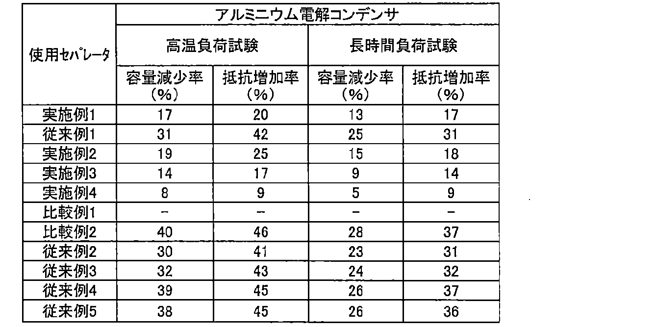

表3からわかる通り、実施例1のアルミニウム電解コンデンサは、従来例1のアルミニウム電解コンデンサと比べ、高温負荷試験及び長時間負荷試験後の容量減少率、抵抗増加率がともに低い。
実施例1のセパレータの抽出塩素含有量は、従来例1のセパレータより多いにもかかわらず、このような結果であることから、アルミニウム電解コンデンサの高温環境下での信頼性や長寿命化には、従来検討されてきた抽出法による塩素含有量でなく、全塩素含有量が重要であるとわかる。
実施例1のセパレータの抽出塩素含有量は、従来例1のセパレータより多いにもかかわらず、このような結果であることから、アルミニウム電解コンデンサの高温環境下での信頼性や長寿命化には、従来検討されてきた抽出法による塩素含有量でなく、全塩素含有量が重要であるとわかる。
定格電圧の異なる実施例2乃至4、比較例2、従来例2乃至5のアルミニウム電解コンデンサを見ても、全塩素含有量を30ppm以下とすることで、従来例と比べ容量減少率及び抵抗増加率を改善できるとわかる。
更に、実施例2、実施例3、実施例4のアルミニウム電解コンデンサの比較から、セパレータの全塩素含有量を15ppm以下、10ppm以下とすることで、更なる高温環境下での信頼性向上や長寿命化に寄与でき、天然繊維と比べ溶剤紡糸セルロース繊維を用いたセパレータが好ましいとわかる。
更に、実施例2、実施例3、実施例4のアルミニウム電解コンデンサの比較から、セパレータの全塩素含有量を15ppm以下、10ppm以下とすることで、更なる高温環境下での信頼性向上や長寿命化に寄与でき、天然繊維と比べ溶剤紡糸セルロース繊維を用いたセパレータが好ましいとわかる。
そして、表3と表4とから、アルミニウム電解コンデンサであっても電気二重層キャパシタであっても、この傾向は共通しているとわかる。
比較例1は、合成繊維のみからなるセパレータである。そして、このセパレータを用いて作製したアルミニウム電解コンデンサ及び電気二重層キャパシタは、初期の静電容量が定格容量より20%以上少なく、抵抗値も大きかった。これは、合成繊維は、セルロース繊維と比べ電解液との親和性が低いため、セパレータが充分に電解液を保持しなかったことが原因と考えられる。このことから、セパレータにはセルロース系繊維を含有することが重要であるとわかる。
以上説明したとおり、全塩素含有量が30ppm以下の本発明のセパレータを用いることで、電気化学素子に近年求められる過酷な使用環境での信頼性向上や、長寿命化に寄与できる。
以上、本実施の形態のセパレータをアルミニウム電解コンデンサ、電気二重層キャパシタについて用いた例を説明した。
本発明に係る電気化学素子において、電極材料及び電解液材料、その他の部材等については、特別に限定を必要とすることはなく、種々の材料を用いることができる。
また、本発明の電気化学素子用セパレータは、本実施の形態例で説明した以外の電気化学素子、例えばリチウムイオンキャパシタやリチウム一次電池、リチウムイオン二次電池といった電気化学素子に適用することも可能である。
本発明に係る電気化学素子において、電極材料及び電解液材料、その他の部材等については、特別に限定を必要とすることはなく、種々の材料を用いることができる。
また、本発明の電気化学素子用セパレータは、本実施の形態例で説明した以外の電気化学素子、例えばリチウムイオンキャパシタやリチウム一次電池、リチウムイオン二次電池といった電気化学素子に適用することも可能である。
Claims (7)
- 一対の電極間に介在し、両電極の隔離と電解液の保持をするためのセパレータであって、
前記セパレータがセルロース系繊維を含有し、
前記セパレータの全塩素含有量が30ppm以下である
ことを特徴とする電気化学素子用セパレータ。 - 前記セルロース系繊維は、天然繊維、又は再生繊維のいずれか一種を含有していることを特徴とする請求項1に記載の電気化学素子用セパレータ。
- 前記天然繊維は、木材繊維、非木材繊維から選択される一種以上の繊維であることを特徴とする請求項2に記載の電気化学素子用セパレータ。
- 前記再生繊維は、溶剤紡糸セルロース繊維であることを特徴とする請求項2に記載の電気化学素子用セパレータ。
- 一対の電極と、
前記一対の電極間に介在するセパレータを備え、
前記セパレータに、請求項1乃至請求項4のいずれか1項に記載の電気化学素子用セパレータを用いた
ことを特徴とする電気化学素子。 - 前記電気化学素子がアルミニウム電解コンデンサであることを特徴とする請求項5に記載の電気化学素子。
- 前記電気化学素子が電気二重層キャパシタであることを特徴とする請求項5に記載の電気化学素子。
Priority Applications (4)
| Application Number | Priority Date | Filing Date | Title |
|---|---|---|---|
| EP18745254.5A EP3576119A4 (en) | 2017-01-27 | 2018-01-19 | SEPARATOR FOR ELECTROCHEMICAL ELEMENT, AND ELECTROCHEMICAL ELEMENT |
| KR1020197017438A KR20190109394A (ko) | 2017-01-27 | 2018-01-19 | 전기 화학 소자용 세퍼레이터 및 전기 화학 소자 |
| US16/471,179 US20190392994A1 (en) | 2017-01-27 | 2018-01-19 | Separator for electrochemical element and electrochemical element |
| CN201880005179.6A CN110121756A (zh) | 2017-01-27 | 2018-01-19 | 电化学元件用分隔件和电化学元件 |
Applications Claiming Priority (2)
| Application Number | Priority Date | Filing Date | Title |
|---|---|---|---|
| JP2017-012915 | 2017-01-27 | ||
| JP2017012915A JP2018121013A (ja) | 2017-01-27 | 2017-01-27 | 電気化学素子用セパレータ及び電気化学素子 |
Publications (1)
| Publication Number | Publication Date |
|---|---|
| WO2018139353A1 true WO2018139353A1 (ja) | 2018-08-02 |
Family
ID=62978211
Family Applications (1)
| Application Number | Title | Priority Date | Filing Date |
|---|---|---|---|
| PCT/JP2018/001526 Ceased WO2018139353A1 (ja) | 2017-01-27 | 2018-01-19 | 電気化学素子用セパレータ及び電気化学素子 |
Country Status (6)
| Country | Link |
|---|---|
| US (1) | US20190392994A1 (ja) |
| EP (1) | EP3576119A4 (ja) |
| JP (1) | JP2018121013A (ja) |
| KR (1) | KR20190109394A (ja) |
| CN (1) | CN110121756A (ja) |
| WO (1) | WO2018139353A1 (ja) |
Families Citing this family (2)
| Publication number | Priority date | Publication date | Assignee | Title |
|---|---|---|---|---|
| JP6989414B2 (ja) * | 2018-02-27 | 2022-01-05 | ニッポン高度紙工業株式会社 | 電気化学素子用セパレータ及び電気化学素子 |
| JP7786135B2 (ja) * | 2021-11-04 | 2025-12-16 | 日本ケミコン株式会社 | 固体電解コンデンサ |
Citations (9)
| Publication number | Priority date | Publication date | Assignee | Title |
|---|---|---|---|---|
| JPS62126622A (ja) | 1985-11-27 | 1987-06-08 | ニツポン高度紙工業株式会社 | 電解コンデンサ |
| JPH06168848A (ja) | 1992-11-27 | 1994-06-14 | Nippon Koudoshi Kogyo Kk | 電解コンデンサ |
| JPH0945586A (ja) | 1995-07-31 | 1997-02-14 | Matsushita Electric Ind Co Ltd | 電気二重層コンデンサ |
| JP2000003834A (ja) | 1998-06-16 | 2000-01-07 | Nippon Kodoshi Corp | 電気二重層コンデンサ |
| JP2002043181A (ja) * | 2000-07-19 | 2002-02-08 | Nippon Kodoshi Corp | 電解コンデンサ |
| JP2012222266A (ja) | 2011-04-13 | 2012-11-12 | Mitsubishi Paper Mills Ltd | 電気化学素子用セパレータ及びそれを用いてなる電気化学素子 |
| JP2015133389A (ja) * | 2014-01-10 | 2015-07-23 | ニッポン高度紙工業株式会社 | セパレータ及び該セパレータを用いたコンデンサ |
| JP2016024918A (ja) * | 2014-07-18 | 2016-02-08 | 三菱製紙株式会社 | 電気化学素子用セパレータの製造方法、その製造方法により製造される電気化学素子用セパレータ及びそれを用いてなる電気化学素子 |
| JP2016072309A (ja) * | 2014-09-26 | 2016-05-09 | 旭化成株式会社 | リチウムイオンキャパシタ |
Family Cites Families (6)
| Publication number | Priority date | Publication date | Assignee | Title |
|---|---|---|---|---|
| CN1860627B (zh) * | 2003-08-06 | 2011-01-26 | 三菱化学株式会社 | 非水电解液二次电池的隔板和利用它的非水电解液二次电池 |
| EP2779188A4 (en) * | 2011-11-11 | 2016-11-16 | Nippon Kodoshi Corp | SEPARATOR FOR AN ELECTROLYTIC CONDENSER AND ELECTROLYTE CONDENSER |
| JP2014123607A (ja) * | 2012-12-20 | 2014-07-03 | Nippon Kodoshi Corp | アルミ電解コンデンサ用セパレータ及びアルミ電解コンデンサ |
| WO2015092898A1 (ja) * | 2013-12-19 | 2015-06-25 | ニッポン高度紙工業株式会社 | キャパシタ用セパレータ及びキャパシタ |
| CA2961540C (en) * | 2014-09-26 | 2020-04-21 | Asahi Kasei Kabushiki Kaisha | Thin-film sheet including cellulose fine-fiber layer |
| JP2017069409A (ja) * | 2015-09-30 | 2017-04-06 | ニッポン高度紙工業株式会社 | 電気化学素子用セパレータ及び電気化学素子 |
-
2017
- 2017-01-27 JP JP2017012915A patent/JP2018121013A/ja active Pending
-
2018
- 2018-01-19 EP EP18745254.5A patent/EP3576119A4/en not_active Withdrawn
- 2018-01-19 KR KR1020197017438A patent/KR20190109394A/ko not_active Ceased
- 2018-01-19 WO PCT/JP2018/001526 patent/WO2018139353A1/ja not_active Ceased
- 2018-01-19 CN CN201880005179.6A patent/CN110121756A/zh active Pending
- 2018-01-19 US US16/471,179 patent/US20190392994A1/en not_active Abandoned
Patent Citations (9)
| Publication number | Priority date | Publication date | Assignee | Title |
|---|---|---|---|---|
| JPS62126622A (ja) | 1985-11-27 | 1987-06-08 | ニツポン高度紙工業株式会社 | 電解コンデンサ |
| JPH06168848A (ja) | 1992-11-27 | 1994-06-14 | Nippon Koudoshi Kogyo Kk | 電解コンデンサ |
| JPH0945586A (ja) | 1995-07-31 | 1997-02-14 | Matsushita Electric Ind Co Ltd | 電気二重層コンデンサ |
| JP2000003834A (ja) | 1998-06-16 | 2000-01-07 | Nippon Kodoshi Corp | 電気二重層コンデンサ |
| JP2002043181A (ja) * | 2000-07-19 | 2002-02-08 | Nippon Kodoshi Corp | 電解コンデンサ |
| JP2012222266A (ja) | 2011-04-13 | 2012-11-12 | Mitsubishi Paper Mills Ltd | 電気化学素子用セパレータ及びそれを用いてなる電気化学素子 |
| JP2015133389A (ja) * | 2014-01-10 | 2015-07-23 | ニッポン高度紙工業株式会社 | セパレータ及び該セパレータを用いたコンデンサ |
| JP2016024918A (ja) * | 2014-07-18 | 2016-02-08 | 三菱製紙株式会社 | 電気化学素子用セパレータの製造方法、その製造方法により製造される電気化学素子用セパレータ及びそれを用いてなる電気化学素子 |
| JP2016072309A (ja) * | 2014-09-26 | 2016-05-09 | 旭化成株式会社 | リチウムイオンキャパシタ |
Non-Patent Citations (1)
| Title |
|---|
| See also references of EP3576119A4 |
Also Published As
| Publication number | Publication date |
|---|---|
| EP3576119A1 (en) | 2019-12-04 |
| JP2018121013A (ja) | 2018-08-02 |
| EP3576119A4 (en) | 2020-09-30 |
| CN110121756A (zh) | 2019-08-13 |
| KR20190109394A (ko) | 2019-09-25 |
| US20190392994A1 (en) | 2019-12-26 |
Similar Documents
| Publication | Publication Date | Title |
|---|---|---|
| EP3447779B1 (en) | Separator for electrochemical element and electrochemical element | |
| US11063319B2 (en) | Separator for electrochemical element and electrochemical element | |
| US20150010828A1 (en) | Separator for alkaline battery and alkaline battery | |
| KR102660222B1 (ko) | 전기 화학 소자용 세퍼레이터 및 전기 화학 소자 | |
| US11094475B2 (en) | Separator for electrochemical element and electrochemical element | |
| WO2018139353A1 (ja) | 電気化学素子用セパレータ及び電気化学素子 | |
| TWI616014B (zh) | 電氣化學元件用分離器以及電氣化學元件 | |
| JP2013179036A (ja) | アルカリ電池用セパレータ及びアルカリ電池 | |
| JP2015015312A (ja) | 電解コンデンサ用セパレータ及びアルミ電解コンデンサ | |
| EP4123675A1 (en) | Separator for electrochemical elements, and electrochemical element | |
| JP2014222706A (ja) | アルミ電解コンデンサ用セパレータおよびアルミ電解コンデンサ | |
| JP2022141392A (ja) | 固体電解コンデンサ用セパレータ | |
| JPH077741B2 (ja) | 電解コンデンサ | |
| KR20260054362A (ko) | 전기화학적 특성이 향상된 분리막, 이를 포함하는 아연이온배터리, 전기화학적 특성이 향상된 분리막 제조 방법, 및 이에 의해 제조된 분리막 | |
| JPH05291080A (ja) | 電解コンデンサ | |
| HK1201992B (en) | Separator for alkaline battery and alkaline battery |
Legal Events
| Date | Code | Title | Description |
|---|---|---|---|
| 121 | Ep: the epo has been informed by wipo that ep was designated in this application |
Ref document number: 18745254 Country of ref document: EP Kind code of ref document: A1 |
|
| ENP | Entry into the national phase |
Ref document number: 20197017438 Country of ref document: KR Kind code of ref document: A |
|
| NENP | Non-entry into the national phase |
Ref country code: DE |
|
| ENP | Entry into the national phase |
Ref document number: 2018745254 Country of ref document: EP Effective date: 20190827 |