WO2018139561A1 - 回転電機 - Google Patents
回転電機 Download PDFInfo
- Publication number
- WO2018139561A1 WO2018139561A1 PCT/JP2018/002372 JP2018002372W WO2018139561A1 WO 2018139561 A1 WO2018139561 A1 WO 2018139561A1 JP 2018002372 W JP2018002372 W JP 2018002372W WO 2018139561 A1 WO2018139561 A1 WO 2018139561A1
- Authority
- WO
- WIPO (PCT)
- Prior art keywords
- magnetic pole
- rotor
- axial direction
- air gap
- stator
- Prior art date
- Legal status (The legal status is an assumption and is not a legal conclusion. Google has not performed a legal analysis and makes no representation as to the accuracy of the status listed.)
- Ceased
Links
Images








Classifications
-
- H—ELECTRICITY
- H02—GENERATION; CONVERSION OR DISTRIBUTION OF ELECTRIC POWER
- H02K—DYNAMO-ELECTRIC MACHINES
- H02K21/00—Synchronous motors having permanent magnets; Synchronous generators having permanent magnets
- H02K21/02—Details
- H02K21/04—Windings on magnets for additional excitation ; Windings and magnets for additional excitation
- H02K21/042—Windings on magnets for additional excitation ; Windings and magnets for additional excitation with permanent magnets and field winding both rotating
- H02K21/044—Rotor of the claw pole type
-
- H—ELECTRICITY
- H02—GENERATION; CONVERSION OR DISTRIBUTION OF ELECTRIC POWER
- H02K—DYNAMO-ELECTRIC MACHINES
- H02K21/00—Synchronous motors having permanent magnets; Synchronous generators having permanent magnets
- H02K21/02—Details
- H02K21/04—Windings on magnets for additional excitation ; Windings and magnets for additional excitation
- H02K21/046—Windings on magnets for additional excitation ; Windings and magnets for additional excitation with rotating permanent magnets and stationary field winding
- H02K21/048—Rotor of the claw pole type
-
- H—ELECTRICITY
- H02—GENERATION; CONVERSION OR DISTRIBUTION OF ELECTRIC POWER
- H02K—DYNAMO-ELECTRIC MACHINES
- H02K1/00—Details of the magnetic circuit
- H02K1/02—Details of the magnetic circuit characterised by the magnetic material
-
- H—ELECTRICITY
- H02—GENERATION; CONVERSION OR DISTRIBUTION OF ELECTRIC POWER
- H02K—DYNAMO-ELECTRIC MACHINES
- H02K19/00—Synchronous motors or generators
- H02K19/02—Synchronous motors
- H02K19/10—Synchronous motors for multi-phase current
- H02K19/103—Motors having windings on the stator and a variable reluctance soft-iron rotor without windings
-
- H—ELECTRICITY
- H02—GENERATION; CONVERSION OR DISTRIBUTION OF ELECTRIC POWER
- H02K—DYNAMO-ELECTRIC MACHINES
- H02K19/00—Synchronous motors or generators
- H02K19/02—Synchronous motors
- H02K19/10—Synchronous motors for multi-phase current
- H02K19/12—Synchronous motors for multi-phase current characterised by the arrangement of exciting windings, e.g. for self-excitation, compounding or pole-changing
-
- H—ELECTRICITY
- H02—GENERATION; CONVERSION OR DISTRIBUTION OF ELECTRIC POWER
- H02K—DYNAMO-ELECTRIC MACHINES
- H02K19/00—Synchronous motors or generators
- H02K19/16—Synchronous generators
- H02K19/22—Synchronous generators having windings each turn of which co-operates alternately with poles of opposite polarity, e.g. heteropolar generators
-
- H—ELECTRICITY
- H02—GENERATION; CONVERSION OR DISTRIBUTION OF ELECTRIC POWER
- H02K—DYNAMO-ELECTRIC MACHINES
- H02K19/00—Synchronous motors or generators
- H02K19/16—Synchronous generators
- H02K19/22—Synchronous generators having windings each turn of which co-operates alternately with poles of opposite polarity, e.g. heteropolar generators
- H02K19/24—Synchronous generators having windings each turn of which co-operates alternately with poles of opposite polarity, e.g. heteropolar generators with variable-reluctance soft-iron rotors without winding
-
- H—ELECTRICITY
- H02—GENERATION; CONVERSION OR DISTRIBUTION OF ELECTRIC POWER
- H02K—DYNAMO-ELECTRIC MACHINES
- H02K19/00—Synchronous motors or generators
- H02K19/16—Synchronous generators
- H02K19/26—Synchronous generators characterised by the arrangement of exciting windings
-
- H—ELECTRICITY
- H02—GENERATION; CONVERSION OR DISTRIBUTION OF ELECTRIC POWER
- H02K—DYNAMO-ELECTRIC MACHINES
- H02K7/00—Arrangements for handling mechanical energy structurally associated with dynamo-electric machines, e.g. structural association with mechanical driving motors or auxiliary dynamo-electric machines
- H02K7/006—Structural association of a motor or generator with the drive train of a motor vehicle
-
- H—ELECTRICITY
- H02—GENERATION; CONVERSION OR DISTRIBUTION OF ELECTRIC POWER
- H02K—DYNAMO-ELECTRIC MACHINES
- H02K2201/00—Specific aspects not provided for in the other groups of this subclass relating to the magnetic circuits
- H02K2201/03—Machines characterised by aspects of the air-gap between rotor and stator
Definitions
- the present invention relates to a brushless winding field type rotating electrical machine disposed on the outer periphery of a starting device.
- Patent Document 1 a rotating electrical machine that supplies magnetic flux from a stationary field coil 102 to a rotor 101 has been proposed as in Patent Document 1 shown in FIG.
- the stator 103 is disposed outside the rotor 101 in the radial direction.
- a power supply device that is, a so-called brush
- Patent Document 2 a structure in which a rotating electric machine is arranged on the outer periphery of a starting device has been proposed.
- the engine can be started by connecting the engine and the rotating electrical machine, and by functioning as a generator during traveling, the starter and alternator that were necessary in conventional automobiles can be eliminated. .
- an object of the present invention is to provide a rotating electrical machine capable of increasing the design freedom and improving the output performance in solving the above-mentioned problems.
- the present invention is configured as follows.
- a brushless winding field type rotating electrical machine that is disposed between an engine and a transmission that are disposed along a rotating shaft and is located between a case that encloses a starting device and the starting device.
- a stator that is held in the case and includes an AC coil that generates a rotating magnetic field using an AC current
- a field core that is held in the case and includes a field coil that is excited by a direct current
- a rotor disposed on an outer periphery of the starting device and held rotatably about the rotation axis with respect to the stator and the field coil;
- a first air gap formed between the stator and the rotor to transfer magnetic flux between the stator and the rotor;
- a second air gap formed between the field core and the rotor and passing a magnetic flux between the field core and the rotor;
- the second air gap provides a rotating electrical machine that is a gap extending along a direction intersecting the axial direction of the rotating shaft at one end surface of the rotor in the axial direction of the rotating shaft.
- only one of the stator and the field coil is disposed in a narrow space on the inner peripheral side of the case and on the outer peripheral side of the starting device. Since only one member needs to be arranged on the coaxial different diameter of the rotating shaft, the degree of freedom in design is increased, and the output performance of the rotating electrical machine can be improved.
- FIG. 2A is a perspective view with the magnetic pole holding member removed from FIG.
- the front view when it sees from the transmission side of the rotary electric machine concerning 1st Embodiment The perspective view of the rotary electric machine concerning 1st Embodiment, The perspective view of the rotor of the rotary electric machine concerning 1st Embodiment, The disassembled perspective view of the rotor of the rotary electric machine concerning 1st Embodiment, Explanatory drawing explaining the relationship between the structure of 1st Embodiment, and the structure of the example of a combination of the conventional literature, Explanatory drawing explaining the structure concerning the modification of 1st Embodiment, Explanatory drawing which shows the arrangement
- FIG. 12A is a partially enlarged view of FIG. Explanatory drawing which shows the arrangement
- FIG. 13A is a perspective view with the magnetic pole holding member removed from FIG. Magnetic flux in the case of being formed obliquely (for example, at an inclination angle of 20 degrees) as in the third embodiment when the respective magnifications of the magnetic flux and electromagnetic force in the case of being formed vertically are set to 1.
- a graph that displays the magnification with the axial electromagnetic force Explanatory drawing explaining the relationship between the structure of 1st Embodiment, and the structure of the example of a combination of the conventional literature, Explanatory drawing which shows the arrangement
- FIG. 7 is a perspective view when cut along a direction perpendicular to the rotation axis of the rotating electrical machine according to the fourth embodiment, and a perspective view with a magnetic pole holding member removed; It is explanatory drawing explaining schematic structure of the conventional rotary electric machine.
- the rotating electrical machine according to the first embodiment of the present invention is disposed between the engine 8 and the transmission 9 along the rotation shaft 7, and includes a case 5 that encloses the starting device 4.
- the brushless winding field type rotating electrical machine 10 is located between the starting device 4 and the starting device 4.
- the rotating electrical machine 10 includes at least a stator 3, a field coil 2, and a rotor 1.
- the stator 3 is fixed and held in a non-rotatable manner in the case 5 and is formed of a cylindrical member having a plurality of slots for winding the AC coil 14.
- the stator 3 includes the AC coil 14 therein, and the AC coil 14.
- a rotating magnetic field is generated by an alternating current flowing through the.
- the field coil 2 is arranged so as to be shifted along the rotation shaft 7 with respect to the stator 3 and the rotor 1, is fixedly held in the case 5 on the transmission 9 side of the stator 3, and is excited by a direct current.
- the field core 6 includes a field coil 2 inside.
- the field coil 2 is shifted along the rotation axis 7 from the stator 3 and the rotor 1, not to the transmission 9 side of the stator 3 but to the engine side of the stator 3 via the second air gap 12. May be arranged (refer to a dashed-dotted area 89 in FIG. 1).
- the rotor 1 is fixedly disposed on the outer periphery of the starting device 4, the outer peripheral surface of the rotor 1 faces the inner peripheral surface of the stator 3, and the end surface on the transmission side of the rotor 1 is the field coil 2. Opposite to the end surface on the engine side, the stator 3 and the field coil 2 are rotatably held around the rotation shaft 7.
- a first air gap 11 is formed between the stator 3 and the rotor 1 to transfer magnetic flux between the stator 3 and the rotor 1.
- the first air gap 11 is a gap extending along the axial direction of the rotary shaft 7 between the inner peripheral surface of the stator 3 and the outer peripheral surface of the rotor 1.
- a second air gap 12 is formed between the field core 6 and the rotor 1 to transfer magnetic flux between the field coil 2 and the rotor 1.
- the second air gap 12 is formed between the field core 6 and the rotor 1 on the shaft 7 on the transmission side in the axial direction of the rotation shaft 7 of the rotor 1 and on the engine-side end surface of the field core 6.
- the axial direction is a gap extending in a crossing direction, for example, a vertical radial direction.
- the field coil 2 is shifted in parallel with the rotor 1 via the second air gap 12 in the axial direction of the rotary shaft 7.
- the rotor 1 is configured by combining a first magnetic pole 21, a second magnetic pole 22, and a magnetic pole holding member 23.
- 3 is a cross-sectional view of the rotary electric machine 10 and the starting device 4 in the center of FIG.
- the first magnetic pole 21 is made of, for example, a soft magnetic material such as iron, and has a plurality of, for example, rectangular thin plate-like claw portions 21b protruding in the axial direction of the rotary shaft 7 from the first annular portion 21a.
- the claw portions 21b are arranged at regular intervals, for example, at regular intervals in the circumferential direction, and the axial lengths of the rotating shafts 7 are all the same.
- the outer peripheral surface of each claw portion 21b is disposed along the outer peripheral surface of the first annular portion 21a. Even if the first magnetic pole 21 and the second magnetic pole 22 are combined, the claw portion 21b is not in contact with the second magnetic pole 22, and a radial gap 16 is formed in the radial direction.
- the second magnetic pole 22 is made of, for example, a soft magnetic material such as iron, is disposed with a radial gap 16 inside the first annular portion 21a, and is disposed so as to partially overlap the first annular portion 21a.
- a plurality of, for example, rectangular plate-shaped convex portions 22b that protrude in the radial direction on the outer circumferential surface of the second annular portion 22a and are disposed with the circumferential gap 17 in the circumferential direction are provided.
- the convex portions 22b are also arranged at a constant interval, for example, at equal intervals in the circumferential direction, and all the heights in the radial direction are the same.
- each convex portion 22b in the axial direction of the rotating shaft 7 is all the same, and are shorter than the claw portions 21b.
- the outer peripheral surface of each convex portion 22 b is arranged on one circle having the same center as the rotation axis of the rotor 1.
- Each convex portion 22b extends to the engine-side edge of the second annular portion 22a to form a first tip locking portion 22c, while it does not extend to the edge of the second annular portion 22a on the transmission side.
- a narrow annular fitting portion 22d is formed without the convex portion 22b.
- the first magnetic pole 21 is moved in the axial direction with respect to the second magnetic pole 22, and each claw portion 21b of the first magnetic pole 21 is inserted into the intermediate portion of the circumferential gap 17 between the adjacent convex portions 22b.
- 21b and convex part 22b are assembled so as to be alternately arranged in the circumferential direction.
- the first annular portion 21a of the first magnetic pole 21 can be disposed outside the fitting portion 22d with the radial gap 16 interposed therebetween.
- there is an axial gap 19 between the convex portion 22b and the first annular portion 21a there is a circumferential direction between the claw portion 21b and the second magnetic pole 22.
- the magnetic pole holding member 23 is further provided.
- the magnetic pole holding member 23 is made of a non-magnetic material such as aluminum or austenitic stainless steel, and is an annular member.
- the first tip locking portion 21c of the claw portion 21b of the first magnetic pole 21 is fitted and fixed.
- a fitting portion 23a for fitting and fixing the second tip locking portion 22c of the convex portion 22b of the second magnetic pole 22 is provided on the outer peripheral side, for example.
- the first tip locking portion 21c and the second tip locking portion 22c are fitted into the fitting portion 23a and fixed by bolting, shrink fitting, brazing, or the like, so that the first magnetic pole 21 and the second magnetic pole 22 are fixed. Is fixed and held by the magnetic pole holding member 23 in a non-contact manner.
- the first tip locking portion 21c of the claw portion 21b of the first magnetic pole 21 and the second tip locking portion 22c of the convex portion 22b of the second magnetic pole 22 are formed of stepped portions, The said step part is each fitted by the engagement recessed part of the fitting part 23a, and is hold
- locking part 22c is arrange
- the magnetic pole holding member 23 is used as a non-magnetic material to eliminate the magnetic flux short-circuit and efficiently magnetize.
- the magnetic pole holding member 23 can mechanically hold the first magnetic pole 21 and the second magnetic pole 22.
- the first tip locking portion 21c of the claw portion 21b of the first magnetic pole 21 is fitted and fixed by the fitting portion 23a of the magnetic pole holding member 23, thereby suppressing the spread of the claw portion 21b due to the rotational centrifugal force, Rotational strength can be improved.
- a field coil magnetic flux 15 is generated when the field coil 2 is energized.
- the field coil magnetic flux 15 is supplied from the field core 6 to the second air gap 12, the first magnetic pole 21 of the rotor 1, the first air gap 11, the stator 3, the first air gap 11, and the second of the rotor 1. It is configured by returning to the field core 6 via the magnetic pole 22 and the second air gap 12.
- the field coil magnetic flux 15 is generated, and the first magnetic pole 21 and the second magnetic pole 22 are, for example, respectively an N pole and an S pole. Magnetized.
- the induced voltage increases in accordance with the rotational speed of the rotor 1, and when the rotational speed reaches the rotational speed of the first explosion lower than the idling rotational speed corresponding to the idling of the engine 8, the driving of the inverter is stopped.
- the process automatically shifts to the power generation mode, that is, when the rotating electrical machine 10 is used as a generator to perform the power generation function.
- the exciting current is adjusted so that the induced voltage becomes constant at a predetermined induced voltage.
- the excitation current is adjusted so that the magnetizing force of the field coil 2 is constant. This means that the field coil 2 functions as a permanent magnet.
- the rotating electrical machine 10 functions as a generator.
- the engine 8 can be started, and can function as a generator (generator) during traveling.
- the second air gap 12 between the field coil 2 and the rotor 1 is provided on the rotary shaft 7.
- the first magnetic pole 21 of the rotor 1 is an annular member and has a shape having a number of claw portions 21b
- the second magnetic pole 22 is an annular member and a shape having a number of protrusions 22b.
- the first and second magnetic poles 21 and 22 are alternately arranged in the circumferential direction, and the first and second magnetic poles 21 and 22 are held by a nonmagnetic magnetic pole holding member 23. According to such a configuration, the following effects can be achieved.
- the rotating electrical machine 110 is arranged on the radially outer side of the starting device 104, and When three members of the stator 103, the rotor 101, and the field coil 102 are arranged from the outside in the radial direction to the inside in the space between the case 105 and the starting device 104, the field coil 102 When the number of turns of the coil is increased in order to increase the magnetic flux, the thickness in the radial direction is increased, the space is not entered, and the magnetic flux cannot be increased.
- the field coil 2 is shifted in the axial direction of the rotating shaft 7 in parallel with the stator 3 and the rotor 1. It is configured. If comprised in this way, it will be only two members, the stator 3 and the rotor 1, in the radial direction outer side of the starting apparatus 4, and the arrangement
- the field coil 2 is disposed at a position shifted in the axial direction from the stator 3 and the rotor 1, the radial direction of the field coil 2 can be reduced without considering the space of the stator 3 and the rotor 1.
- the magnetic flux of the field coil 2 can be increased by increasing the thickness. Therefore, the degree of freedom in design can be increased.
- the clearance dimension between the rotor 101 and the field coil 102 is It is necessary to design in consideration of a change in thickness such as bulge due to the centrifugal force of the rotor 101, and in general, it is necessary to design larger than a necessary dimension.
- the field coil 2 is arranged in the axial direction with respect to the stator 3 and the rotor 1, and the gap between the field coil 2 and the rotor 1. If the second air gap 12 is extended in the radial direction, it is not necessary to consider changes in thickness such as swelling due to the centrifugal force of the rotor 1, and only the distance between the second air gaps 12 along the axial direction is adjusted. Therefore, the influence of centrifugal force can be reduced.
- the field coil 2 can be arranged in any space on the engine side or the transmission side in the axial direction of the rotor 1 to effectively utilize the space. Can do.
- the rotor 1 of the rotating electrical machine 10 is connected to a starting device 4 that is a synchronous rotating member that rotates synchronously with the output shaft (rotating shaft) 7 of the engine 8, and the center axis of the output shaft of the engine 8 is connected to the rotor 1. Since the rotating electrical machine 10 is arranged so as to be a rotating shaft, the rotational driving force of the rotating electrical machine 10 can be reliably transmitted to the engine 8 even when cold, and the engine 8 can be reliably started when cold. .
- the present invention is not limited to the first embodiment, and can be implemented in various other modes.
- the position of the stator 3 and the position of the field coil 2 are exchanged so that the field coil 2 is placed radially outward of the rotor 1.
- the arrangement may be such that the stator 3 is displaced in the axial direction of the rotation shaft 7 of the rotor 1. That is, the first air gap 11 between the rotor 1 and the stator 3 is formed as a gap extending in a direction intersecting the axial direction of the rotary shaft 7, for example, along a perpendicular radial direction.
- the second air gap 12 between the field coil 2 and the rotor 1 is formed as a gap extending along the axial direction of the rotating shaft 7.
- the 1st air gap 11 between the rotor 1 and the stator 3 is radial direction perpendicular
- FIGS. 9 to 11 As shown in FIGS. 9 to 11, as a second embodiment of the present invention, in the configuration of the first embodiment, a structure in which a permanent magnet 27 is disposed inside the rotor 1 may be employed.
- the second annular portion 22a of the second magnetic pole 22 is located at the same position in the circumferential direction as each claw portion 21b of the first magnetic pole 21, and on the inner diameter side of each claw portion 21b of the first magnetic pole 21.
- a rectangular plate-shaped permanent magnet 27 is sandwiched between the inner peripheral surface of each claw portion 21b and the outer peripheral surface of the second annular portion 22a. With this arrangement, as shown in FIG. 10, the magnet magnetic flux 28 of the permanent magnet 27 is formed between each claw portion 21 b of the first magnetic pole 21 and the convex portion 22 b of the second magnetic pole 22.
- the permanent magnet 27 is a magnet made mainly of neodymium or a magnet made mainly of ferrite. Specifically, as the permanent magnet 27, various types of permanent magnets such as, for example, an SmCo magnet, an AlNiCo magnet, or a neodymium bond magnet can be used. The permanent magnet 27 is disposed on the entire inner surface of each claw portion 21b or a part thereof.
- the output performance can be improved by using the magnetic flux 28 of the permanent magnet 27 in addition to the magnetic flux generated in the rotor 1 by the field coil 2. Further, by holding the permanent magnet 27 with the claw portion 21b and holding it, the strength of the permanent magnet 27 against the centrifugal force can be reinforced, the deformation of the permanent magnet 27 due to the centrifugal force can be prevented, and the centrifugal strength at the time of high rotation Can be improved.
- the second air gap 12 is not limited to the gap extending along the radial direction perpendicular to the axial direction of the rotating shaft 7 as described in the first and second embodiments.
- the gap may be inclined with respect to the direction. An example having such a gap will be described below.
- a rotating electrical machine is disposed between an engine 8 and a transmission 9 along a rotating shaft 7, and includes a case 5 that encloses a starting device 4.
- the brushless winding field type rotating electrical machine 10 is located between the starting device 4 and the starting device 4.
- the rotating electrical machine 10 includes at least a stator 3, a field coil 2, and a rotor 1.
- the stator 3 is fixed and held in a non-rotatable manner in the case 5 and is formed of a cylindrical member having a plurality of slots for winding the AC coil 14.
- the stator 3 includes the AC coil 14 therein, and the AC coil 14.
- a rotating magnetic field is generated by an alternating current flowing through the.
- the field coil 2 is arranged so as to be shifted along the rotation shaft 7 with respect to the stator 3 and the rotor 1, is fixedly held in the case 5 on the transmission 9 side of the stator 3, and is excited by a direct current.
- the field core 6 includes a field coil 2 inside. The field coil 2 is shifted along the rotation axis 7 from the stator 3 and the rotor 1, not to the transmission 9 side of the stator 3 but to the engine side of the stator 3 via the second air gap 212. (Refer to the region 89 shown by the alternate long and short dash line in FIG. 12A).
- the rotor 1 is fixedly disposed on the outer periphery of the starting device 4, the outer peripheral surface of the rotor 1 faces the inner peripheral surface of the stator 3, and the end surface on the transmission side of the rotor 1 is the field coil 2. Opposite to the end surface on the engine side, the stator 3 and the field coil 2 are rotatably held around the rotation shaft 7.
- a first air gap 11 is formed between the stator 3 and the rotor 1 to transfer magnetic flux between the stator 3 and the rotor 1.
- the first air gap 11 is a gap extending along the axial direction of the rotary shaft 7 between the inner peripheral surface of the stator 3 and the outer peripheral surface of the rotor 1.
- a second air gap 212 is formed between the field core 6 and the rotor 1 to transfer magnetic flux between the field coil 2 and the rotor 1.
- the second air gap 212 has a rotary shaft 7 between the field core 6 and the rotor 1 on the transmission-side end surface of the rotation shaft 7 of the rotor 1 and the engine-side end surface of the field core 6.
- the gap is inclined at an inclination angle ⁇ with respect to the axial direction.
- the second air gap 212 is provided between the field core 6 and the second magnetic pole 22 of the rotor 1 on the transmission side in the axial direction of the rotating shaft 7 of the rotor 1.
- the end face on the engine side of the field core 6 and the end face on the transmission side in the axial direction of the rotary shaft 7 of the rotor 1 and the field core between the field core 6 and the first magnetic pole 21 of the rotor 1. 6 are formed on the end face on the engine side.
- the gap 212 includes a first vertical portion 212 a that is perpendicular to the axial direction of the rotary shaft 7 from the center side of the rotary shaft 7, and a gap that is inclined at an inclination angle ⁇ with respect to the axial direction of the rotary shaft 7.
- the portion 212b and a second vertical portion 212c having a gap perpendicular to the axial direction of the rotary shaft 7 are configured.
- the first vertical portion 212a, the inclined portion 212b, and the second vertical portion 212c are continuously connected. As an inclination direction of the inclined portion 212b, as it goes from the inner side to the outer side in the radial direction, the inclination portion 212b is gradually inclined from the engine side toward the transmission side.
- the gaps between the first vertical portion 212a, the inclined portion 212b, and the second vertical portion 212c are substantially the same.
- the gap 212 includes a first vertical portion 212 a that is perpendicular to the axial direction of the rotary shaft 7 from the center side of the rotary shaft 7, and a gap that is inclined at an inclination angle ⁇ with respect to the axial direction of the rotary shaft 7.
- the portion 212b and a second vertical portion 212c having a gap perpendicular to the axial direction of the rotary shaft 7 are configured.
- the first vertical portion 212a, the inclined portion 212b, and the second vertical portion 212c are continuously connected.
- the second air gap 212 on the second magnetic pole 22 side is gradually inclined from the transmission side to the engine side. Yes.
- the gaps between the first vertical portion 212a, the inclined portion 212b, and the second vertical portion 212c are substantially the same.
- the inclination direction of the second air gap 212 on the first magnetic pole 21 side and the inclination direction of the second air gap 212 on the second magnetic pole 22 side are matched, as shown in FIG. It is arrange
- This approximately V-shape is an example, and may be a reverse approximately V-shape or a parallel shape. That is, the inclination direction of the second air gap 212 on the first magnetic pole 21 side and the inclination direction of the second air gap 212 on the second magnetic pole 22 side may be arbitrary directions, and the inclination angle may also be arbitrary. is there. As an example, it is preferable from the viewpoint of the balance between the magnetic flux and the axial force if the two tilt directions are the same.
- At least the inclined portion 212b may be provided, and about one or two vertical portions 212a or 212c may be provided.
- the second air gap 212 between the rotor 1 and the field coil 2 is formed as a vertical surface in the axial direction of the rotating shaft 7, the air resistance is increased because the air gap cross-sectional area is small, and the rotor field is increased. There is a possibility that the required field current will be high. Further, when the second air gap 212 is formed perpendicular to the axial direction of the rotary shaft 7, an electromagnetic attractive force is generated in the axial direction, and a large axial force can act on a bearing (not shown) that holds the starting device 4. There is sex.
- the effective magnetic path width of the second air gap 212 is equal to the thickness of the field core 6 and the magnetic pole thickness in the cross section. It is. Further, when the field core 6 is excited, an electromagnetic attractive force acts between the field core 6 and the rotor 1, but the second air gap 212 is formed perpendicular to the axial direction of the rotating shaft 7. If this is done, all the electromagnetic attractive forces act as axial forces.
- the second air gap 212 is formed to be inclined with respect to the axial direction of the rotary shaft 7 as in the third embodiment, the second air gap is compared to the case where the second air gap 212 is formed vertically.
- the effective magnetic path width of the gap 212 can be expanded, and the axial force can be reduced by dispersing the electromagnetic attractive force not only in the axial force but also in the radial force.
- the magnetic flux and the electromagnetic force when formed vertically are shown by a bar graph 91
- the magnetic flux and the electromagnetic force when formed obliquely as in the third embodiment are shown by a bar graph 92.
- the respective magnifications of the magnetic flux and the electromagnetic force when formed vertically are set to 1
- the magnification 1 of the magnetic flux and the electromagnetic force when formed obliquely as in the third embodiment. .04 and 0.76 are displayed.
- the magnetic flux is increased by increasing the effective magnetic path width than in the case of being formed vertically, and the electromagnetic attraction force, that is, the electromagnetic force due to the dispersion to the radial force. You can see that the power is getting smaller.
- the axial magnetic force applied to the bearing can be reduced by reducing the axial electromagnetic attractive force.
- drag torque can be reduced and vehicle fuel consumption can be improved.
- the magnetic resistance can be lowered and the field current can be reduced.
- the efficiency of the rotating electrical machine 10 can be improved, and the vehicle fuel consumption can be further improved.
- each inclined portion 212b is, for example, in the range of 10 degrees to 25 degrees with respect to the axial direction of the rotating shaft 7.
- the inclination direction of the inclined portion 212b described above may be reversed between the first magnetic pole 21 and the second magnetic pole 22. That is, the inclined portion 212b on the second magnetic pole 22 side gradually inclines from the transmission side to the engine side as it goes from the inner side to the outer side in the radial direction, while the inclined portion 212b on the first magnetic pole 21 side As it goes from the inner side to the outer side in the radial direction, it may be inclined so as to gradually go from the engine side to the transmission side.
- the second air gap 212 may be configured only by the inclined portion 212b without the vertical portions 212a and 212c.
- the field coil 2 is displaced in parallel with the rotor 1 via the second air gap 212 in the axial direction of the rotary shaft 7.
- the configuration corresponding to FIGS. 3 to 6 of the first embodiment is the same as the configuration of the first embodiment, and the description and illustration thereof are omitted.
- a field coil magnetic flux 15 is generated when the field coil 2 is energized.
- the field coil magnetic flux 15 is supplied from the field core 6 to the second air gap 212, the first magnetic pole 21 of the rotor 1, the first air gap 11, the stator 3, the first air gap 11, and the second of the rotor 1. It is configured by returning to the field core 6 via the magnetic pole 22 and the second air gap 212.
- the field coil magnetic flux 15 is generated, and the first magnetic pole 21 and the second magnetic pole 22 are, for example, respectively an N pole and an S pole. Magnetized.
- the induced voltage increases in accordance with the rotational speed of the rotor 1, and when the rotational speed reaches the rotational speed of the first explosion lower than the idling rotational speed corresponding to the idling of the engine 8, the driving of the inverter is stopped.
- the process automatically shifts to the power generation mode, that is, when the rotating electrical machine 10 is used as a generator to perform the power generation function.
- the exciting current is adjusted so that the induced voltage becomes constant at a predetermined induced voltage.
- the excitation current is adjusted so that the magnetizing force of the field coil 2 is constant. This means that the field coil 2 functions as a permanent magnet.
- the rotating electrical machine 10 functions as a generator.
- the engine 8 can be started, and can function as a generator (generator) during traveling.
- the second air gap 212 between the field coil 2 and the rotor 1 is provided on the rotating shaft 7. It is inclined with respect to.
- the first magnetic pole 21 of the rotor 1 is an annular member and has a shape having a number of claw portions 21b
- the second magnetic pole 22 is an annular member and a shape having a number of protrusions 22b.
- the first and second magnetic poles 21 and 22 are alternately arranged in the circumferential direction, and the first and second magnetic poles 21 and 22 are held by a nonmagnetic magnetic pole holding member 23. According to such a configuration, the following effects can be achieved.
- the rotating electrical machine 110 is arranged on the radially outer side of the starting device 104, and When three members of the stator 103, the rotor 101, and the field coil 102 are arranged from the outside in the radial direction to the inside in the space between the case 105 and the starting device 104, the field coil 102 When the number of turns of the coil is increased in order to increase the magnetic flux, the thickness in the radial direction is increased, the space is not entered, and the magnetic flux cannot be increased.
- the field coil 2 is shifted in the axial direction of the rotating shaft 7 with respect to the stator 3 and the rotor 1 and arranged in parallel. It is configured. If comprised in this way, it will be only two members, the stator 3 and the rotor 1, in the radial direction outer side of the starting apparatus 4, and the arrangement
- the field coil 2 is disposed at a position shifted in the axial direction from the stator 3 and the rotor 1, the radial direction of the field coil 2 can be reduced without considering the space of the stator 3 and the rotor 1.
- the magnetic flux of the field coil 2 can be increased by increasing the thickness. Therefore, the degree of freedom in design can be increased.
- the clearance dimension between the rotor 101 and the field coil 102 is It is necessary to design in consideration of a change in thickness such as bulge due to the centrifugal force of the rotor 101, and in general, it is necessary to design larger than a necessary dimension.
- the field coil 2 is shifted in the axial direction with respect to the stator 3 and the rotor 1, and the gap between the field coil 2 and the rotor 1. If the second air gap 212 is inclined with respect to the axial direction, it is possible to improve the efficiency of the rotating electrical machine 10 and reduce the axial force as described above.
- the field coil 2 can be arranged in any space on the engine side or the transmission side in the axial direction of the rotor 1 to effectively utilize the space. Can do.
- the rotor 1 of the rotating electrical machine 10 is connected to a starting device 4 that is a synchronous rotating member that rotates synchronously with the output shaft (rotating shaft) 7 of the engine 8, and the center axis of the output shaft of the engine 8 is connected to the rotor 1. Since the rotating electrical machine 10 is arranged so as to be a rotating shaft, the rotational driving force of the rotating electrical machine 10 can be reliably transmitted to the engine 8 even when cold, and the engine 8 can be reliably started when cold. .
- the third embodiment in addition to the rotor 1, only one of the stator 3 and the field coil 2 is placed in a narrow space on the inner peripheral side of the case 5 and on the outer peripheral side of the starting device 4.
- the second air gap 212 has an inclined portion 212b that is a gap inclined with respect to the axial direction of the rotating shaft 7 on one end face in the axial direction of the rotating shaft 7 of the rotor 1. Efficiency can be improved and axial force can be reduced.
- FIGS. 15 to 17 As shown in FIGS. 15 to 17, as a fourth embodiment of the present invention, in the configuration of the third embodiment, a structure in which a permanent magnet 27 is arranged inside the rotor 1 may be used.
- the second annular portion 22a of the second magnetic pole 22 is located at the same position in the circumferential direction as each claw portion 21b of the first magnetic pole 21, and on the inner diameter side of each claw portion 21b of the first magnetic pole 21.
- a rectangular plate-shaped permanent magnet 27 is sandwiched between the inner peripheral surface of each claw portion 21b and the outer peripheral surface of the second annular portion 22a. With this arrangement, as shown in FIG. 16, the magnet magnetic flux 28 of the permanent magnet 27 is formed between each claw portion 21 b of the first magnetic pole 21 and the convex portion 22 b of the second magnetic pole 22.
- the permanent magnet 27 is a magnet made mainly of neodymium or a magnet made mainly of ferrite. Specifically, as the permanent magnet 27, various types of permanent magnets such as, for example, an SmCo magnet, an AlNiCo magnet, or a neodymium bond magnet can be used. The permanent magnet 27 is disposed on the entire inner surface of each claw portion 21b or a part thereof.
- the output performance can be improved by using the magnetic flux 28 of the permanent magnet 27 in addition to the magnetic flux generated in the rotor 1 by the field coil 2. Further, by holding the permanent magnet 27 with the claw portion 21b held, the strength of the permanent magnet 27 against the centrifugal force can be reinforced, the deformation of the permanent magnet 27 due to the centrifugal force can be prevented, and the centrifugal strength at high rotation Can be improved.
- the rotating electrical machine according to the above aspect of the present invention has a greater degree of design freedom, can improve output performance, and integrates the power generation function and engine starting function of the alternator and starter motor of the vehicle. It is useful as a device.
Landscapes
- Engineering & Computer Science (AREA)
- Power Engineering (AREA)
- Synchronous Machinery (AREA)
- Iron Core Of Rotating Electric Machines (AREA)
- Permanent Field Magnets Of Synchronous Machinery (AREA)
- Connection Of Motors, Electrical Generators, Mechanical Devices, And The Like (AREA)
Abstract
回転軸(7)沿いのエンジン(8)と変速機(9)との間に配置され、発進装置(4)を内包するケース(5)と発進装置との間に位置するブラシレス巻線界磁型回転電機(10)であって、ケースに保持され、交流電流により回転磁界を発生する交流コイル(14)を内部に備えた固定子(3)と、ケースに保持され、直流電流により励磁する界磁コイル(2)を内部に備えた界磁コア(6)と、発進装置の外周に配置され、固定子及び界磁コイルに対し回転自在に保持される回転子(1)と、固定子と回転子との間に形成されて両者間で磁束を受け渡す第1エアギャップ(11)と、界磁コアと回転子との間に形成されて両者間で磁束を受け渡す第2エアギャップ(12)とを備え、第2エアギャップは、回転子の回転軸の軸方向の一方の端面において、回転軸の軸方向とは交差する方向沿いに延在する隙間である。
Description
本発明は、発進装置の外周に配置されるブラシレス巻線界磁型回転電機に関する。
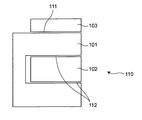
従来技術として、図18に示す特許文献1のように、回転子101に対して静止した界磁コイル102から磁束を供給する回転電機が提案されている。固定子103は回転子101の径方向の外側に配置されている。このような構造により、従来、回転子101を磁化するために必要であった電力供給装置、所謂ブラシを用いたスリップリングを廃止することができる。これが、ブラシレス巻線界磁型回転電機110である。なお、固定子103と回転子101との間には第1エアギャップ111があり、界磁コイル102と回転子101との間には第2エアギャップ112があり、両方とも回転軸107の軸方向沿いに延在している。
また、特許文献2のように、発進装置の外周に回転電機を配置する構造が提案されている。このような構造とし、エンジンと回転電機とを連結することでエンジン始動を可能とし、かつ走行中はジェネレータとして機能する事で、従来の自動車で必要であったスタータ及びオルタネータを廃止する事ができる。
これら2つの特許文献を組み合わせて、すなわち、図7の(b)に示すように、発進装置104の外周にブラシレス巻線界磁型回転電機110を配置しようとした場合、2つの特許文献の構造同士の組み合わせでは、ケース105の内周側でかつ、発進装置104の外周側という狭小なる空間に、ケース105に固定される固定子103と、回転子101と、界磁コイル102との3つの部材を回転軸107の同軸異径上に配置するため、回転電機110の占める体積に厳しい制約があり、設計自由度が限られてしまい、回転電機110の出力性能が限定されてしまうという課題がある。
従って、本発明の目的は、前記問題を解決することにあって、設計自由度を大きくすることができて、出力性能を向上させることができる回転電機を提供することにある。
前記目的を達成するために、本発明は以下のように構成する。
本発明の1つの態様によれば、回転軸沿いのエンジンと変速機との間に配置され、発進装置を内包するケースと前記発進装置との間に位置するブラシレス巻線界磁型回転電機であって、
前記ケースに保持され、交流電流により回転磁界を発生する交流コイルを内部に備えた固定子と、
前記ケースに保持され、直流電流により励磁する界磁コイルを内部に備えた界磁コアと、
前記発進装置の外周に配置され、前記固定子及び前記界磁コイルに対し前記回転軸周りに回転自在に保持される回転子と、
前記固定子と前記回転子との間に形成されて前記固定子と前記回転子との間で磁束を受け渡す第1エアギャップと、
前記界磁コアと前記回転子との間に形成されて前記界磁コアと前記回転子との間で磁束を受け渡す第2エアギャップとを備えて、
前記第2エアギャップは、前記回転子の前記回転軸の軸方向の一方の端面において、前記回転軸の前記軸方向とは交差する方向沿いに延在する隙間である、回転電機を提供する。
前記ケースに保持され、交流電流により回転磁界を発生する交流コイルを内部に備えた固定子と、
前記ケースに保持され、直流電流により励磁する界磁コイルを内部に備えた界磁コアと、
前記発進装置の外周に配置され、前記固定子及び前記界磁コイルに対し前記回転軸周りに回転自在に保持される回転子と、
前記固定子と前記回転子との間に形成されて前記固定子と前記回転子との間で磁束を受け渡す第1エアギャップと、
前記界磁コアと前記回転子との間に形成されて前記界磁コアと前記回転子との間で磁束を受け渡す第2エアギャップとを備えて、
前記第2エアギャップは、前記回転子の前記回転軸の軸方向の一方の端面において、前記回転軸の前記軸方向とは交差する方向沿いに延在する隙間である、回転電機を提供する。
本発明の前記態様によれば、ケースの内周側でかつ発進装置の外周側という狭小なる空間に、回転子以外に、固定子又は界磁コイルのいずれか一方のみを配置させることにより、2つの部材を回転軸の同軸異径上に配置するだけでよいため、設計自由度が大きくなり、回転電機の出力性能を向上させることができる。
本発明のこれらと他の目的と特徴は、添付された図面についての実施形態に関連した次の記述から明らかになる。この図面においては、
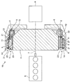
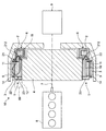
本発明の第1実施形態にかかる回転電機の回転軸と垂直な方向沿いに大略切断したときの断面で示す回転電機とエンジン及び変速機との配置関係を示す説明図、
第1実施形態にかかる回転電機の回転軸と垂直な方向沿いに切断したときの斜視図、
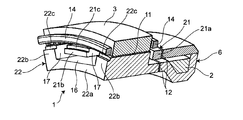
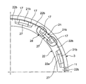
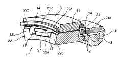
図2Aから磁極保持部材を取り除いた状態での斜視図、
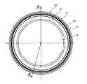
第1実施形態にかかる回転電機の変速機側から見たときの正面図、
第1実施形態にかかる回転電機の斜視図、
第1実施形態にかかる回転電機の回転子の斜視図、
第1実施形態にかかる回転電機の回転子の分解斜視図、
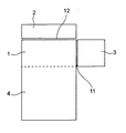
第1実施形態の構成と従来の文献の組み合わせ例の構成との関係を説明する説明図、
第1実施形態の変形例にかかる構成を説明する説明図、
本発明の第2実施形態にかかる回転電機の回転軸と垂直な方向沿いに大略切断したときの断面で示す回転電機とエンジン及び変速機との配置関係を示す説明図、
第2実施形態にかかる回転電機の部分正面図、
第2実施形態にかかる回転電機の回転軸と垂直な方向沿いに切断したときの斜視図であって磁極保持部材を取り除いた状態での斜視図、
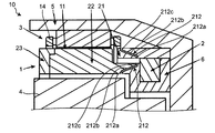
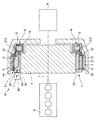
本発明の第3実施形態にかかる回転電機の回転軸と垂直な方向沿いに大略切断したときの断面で示す回転電機とエンジン及び変速機との配置関係を示す説明図、
図12Aの部分拡大図、
本発明の第3実施形態の変形例にかかる回転電機の回転軸と垂直な方向沿いに大略切断したときの断面で示す回転電機とエンジン及び変速機との配置関係を示す説明図、
第3実施形態にかかる回転電機の回転軸と垂直な方向沿いに切断したときの斜視図、
図13Aから磁極保持部材を取り除いた状態での斜視図、
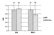
垂直に形成されている場合の磁束と電磁力とのそれぞれの倍率を1としたときの、第3実施形態のように斜めに(例えば傾斜角度が20度で)形成されている場合の磁束と軸方向電磁力との倍率を表示するグラフ、
第1実施形態の構成と従来の文献の組み合わせ例の構成との関係を説明する説明図、
本発明の第4実施形態にかかる回転電機の回転軸と垂直な方向沿いに大略切断したときの断面で示す回転電機とエンジン及び変速機との配置関係を示す説明図、
第4実施形態にかかる回転電機の部分正面図、
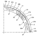
第4実施形態にかかる回転電機の回転軸と垂直な方向沿いに切断したときの斜視図であって磁極保持部材を取り除いた状態での斜視図、
従来の回転電機の概略構成を説明する説明図である。
以下、図面を参照して本発明における実施形態を詳細に説明する。
(第1実施形態)
本発明の第1実施形態にかかる回転電機は、図1~図2Bに示すように、回転軸7沿いのエンジン8と変速機9との間に配置され、発進装置4を内包するケース5と発進装置4との間に位置するブラシレス巻線界磁型回転電機10である。この回転電機10は、少なくとも、固定子3と、界磁コイル2と、回転子1とを備えている。
本発明の第1実施形態にかかる回転電機は、図1~図2Bに示すように、回転軸7沿いのエンジン8と変速機9との間に配置され、発進装置4を内包するケース5と発進装置4との間に位置するブラシレス巻線界磁型回転電機10である。この回転電機10は、少なくとも、固定子3と、界磁コイル2と、回転子1とを備えている。
固定子3は、ケース5に回転不可に固定保持され、交流コイル14を巻回するための複数のスロットを具備する円筒状の部材で構成され、交流コイル14を内部に備えて、交流コイル14に流れる交流電流により回転磁界を発生する。
界磁コイル2は、固定子3及び回転子1よりも回転軸7沿いにずらせて配置されて、固定子3の変速機9側でケース5に固定保持され、直流電流により励磁する。界磁コア6は、界磁コイル2を内部に備えている。なお、界磁コイル2は、固定子3及び回転子1よりも回転軸7沿いに、固定子3の変速機9側ではなく、第2エアギャップ12を介して固定子3のエンジン側にずらせて配置してもよい(図1の一点鎖線の領域89を参照)。
回転子1は、発進装置4の外周に固定配置され、回転子1の外周面が固定子3の内周面に対向し、かつ、回転子1の変速機側の端面が界磁コイル2のエンジン側の端面に対向して、回転軸7の周りで固定子3及び界磁コイル2に対し回転自在に保持されている。
固定子3と回転子1との間には、第1エアギャップ11が形成されて、固定子3と回転子1との間で磁束を受け渡している。第1エアギャップ11は、固定子3の内周面と回転子1の外周面との間で回転軸7の軸方向沿いに延在する隙間である。
界磁コア6と回転子1との間には、第2エアギャップ12が形成されて、界磁コイル2と回転子1との間で磁束を受け渡している。第2エアギャップ12は、界磁コア6と回転子1との間で回転子1の回転軸7の軸方向の変速機側の端面と界磁コア6のエンジン側の端面において、回転軸7の軸方向とは交差する方向、例えば垂直な径方向沿いに延在する隙間である。
よって、界磁コイル2は、回転子1に対して、第2エアギャップ12を介して回転軸7の軸方向にずらされて並列して配置されている。
一方、図3~図6に示すように、回転子1は、第1磁極21と、第2磁極22と、磁極保持部材23とが組み合わされて構成されている。なお、図3のA-A線断面図が図1の中央の回転電機10と発進装置4などの断面図である。
第1磁極21は、例えば鉄などの軟磁性体で構成され、第1円環部21aから回転軸7の軸方向に突き出た複数の例えば矩形薄板状の爪部21bを有している。爪部21bは、周方向に一定間隔、例えば等間隔に配置され、回転軸7の軸方向の長さはすべて同じである。各爪部21bの外周面は第1円環部21aの外周面沿いに配置されている。爪部21bは、第1磁極21と第2磁極22とが組み合わされても、第2磁極22とは非接触であり、径方向には径方向隙間16が形成されている。
第2磁極22は、例えば鉄などの軟磁性体で構成され、第1円環部21aの内側に径方向隙間16をあけて配置され、第1円環部21aと部分的に重なるように配置された第2円環部22aの外周面に径方向に突出しかつ周方向には周方向隙間17を有して配置された複数の例えば矩形板状の凸部22bを有している。凸部22bも、周方向に一定間隔、例えば等間隔に配置され、径方向の高さはすべて同じである。凸部22bの回転軸7の軸方向の長さはすべて同じであり、爪部21bよりも短くなっている。各凸部22bの外周面は回転子1の回転軸心と同一中心の1つの円上に配置されている。各凸部22bは、第2円環部22aのエンジン側の端縁まで延びて第1先端係止部22cを形成する一方、第2円環部22aの変速機側には端縁まで延びずに、凸部22bが無く細幅の円環状のはめ込み部22dを形成している。第1磁極21を第2磁極22に対して軸方向に移動させて、第1磁極21の各爪部21bを隣接する凸部22b間の周方向隙間17の中間部に挿入して、爪部21bと凸部22bとが周方向に交互に配置されように組み付ける。このとき、はめ込み部22dの外側に、径方向隙間16を挟んで第1磁極21の第1円環部21aを配置できるようにしている。組み付けた状態では、図5に示すように、凸部22bと第1円環部21aとの間に軸方向隙間19があり、爪部21bと第2磁極22との間には、周方向に周方向隙間17があり、かつ、径方向にも径方向隙間16がある。よって、第1磁極21と第2磁極22とは非接触に維持されている。この状態で固定するため、磁極保持部材23をさらに備えている。
磁極保持部材23は、例えばアルミニウム又はオーステナイト系ステンレス鋼などの非磁性体で構成され、円環状の部材であって、第1磁極21の爪部21bの第1先端係止部21cを嵌合固定するとともに第2磁極22の凸部22bの第2先端係止部22cを嵌合固定する嵌合部23aを例えば外周側に有している。第1先端係止部21cと第2先端係止部22cとが嵌合部23aに嵌合され、ボルト止め、焼嵌め、又はロウ付けなどで固定されて、第1磁極21と第2磁極22とは非接触に磁極保持部材23で固定保持されている。
第1磁極21の爪部21bの第1先端係止部21cと第2磁極22の凸部22bの第2先端係止部22cとは、具体的な例としては、段部で形成されて、当該段部が嵌合部23aの係合凹部にそれぞれ嵌合されて、径方向に対して固定的に保持されている。第2先端係止部22cは、一例として凸部22bの先端に配置しているが、第2円環部22aの先端に配置してもよい。このように構成すれば、界磁コイル2から磁束を流して第1磁極21と第2磁極22とを磁化するとき、磁極保持部材23を非磁性体として磁束ショートを無くし、効率的に磁化することができるとともに、磁極保持部材23で第1磁極21と第2磁極22とを機械的に保持することができる。また、第1磁極21の爪部21bの第1先端係止部21cを磁極保持部材23の嵌合部23aで嵌合固定保持する事により、回転遠心力による爪部21bの広がりを抑制し、回転強度を向上する事ができる。
以上のように構成された回転電機10においては、界磁コイル2が通電されると、界磁コイル磁束15が発生する。界磁コイル磁束15は、界磁コア6から、第2エアギャップ12と回転子1の第1磁極21と第1エアギャップ11と固定子3と第1エアギャップ11と回転子1の第2磁極22と第2エアギャップ12とを介して、界磁コア6に戻ることにより構成されている。このとき、例えば、直流電流が界磁コイル2に通電されれば、界磁コイル磁束15を発生させ、第1磁極21と第2磁極22とは、それぞれ、例えばN極とS極とにそれぞれ磁化されている。
このような回転電機10において、まず、回転電機10をスタータとして始動機能を発揮させる場合について説明する。エンジン8の始動指令に基づき、図示しないインバータを駆動して固定子3に三相交流電流を流して固定子3を磁化するとともに、界磁コイル2に電流を流す。界磁コイル2に電流を流して、回転子1の第1磁極21と第2磁極22とを励磁する。この結果、回転子1が固定子3に対して回転を開始するとともに、固定子3において誘起電圧を有する起電力が発生する。
その後、誘起電圧は回転子1の回転速度に応じて増加し、回転速度がエンジン8のアイドリングに対応するアイドリング回転速度より低い初爆の回転速度に到達したとき、インバータの駆動を停止し、以後、所定の誘起電圧(要求電圧)を保持するように、自動的に発電モード、すなわち、回転電機10を発電機として発電機能を発揮させる場合に移行する。
この発電モードでは、界磁コイル2を励磁し続けるとき、誘起電圧が所定の誘起電圧で一定になるように、励磁電流を調整する。励磁電流を調整するとき、まず、界磁コイル2の磁化力が一定となるように励磁電流を調整する。これは、界磁コイル2が、あたかも永久磁石として機能することを意味している。このように、あたかも永久磁石が配置されたかのような状態で、回転子1が回転すると、回転電機10は発電機として機能することになる。
この結果、エンジン8と回転電機10とを連結することで、エンジン始動を可能とし、かつ走行中はジェネレータ(発電機)として機能する事ができる。
前記第1実施形態によれば、自動車発進装置4の外周に配置するブラシレス巻線界磁型回転電機10において、界磁コイル2と回転子1との間の第2エアギャップ12を回転軸7と垂直な平面上に配置している。特に、回転子1の第1磁極21を円環状の部材でかつ多数の爪部21bを有する形状とし、第2磁極22を円環状の部材でかつ多数の凸部22bを有する形状とし、これらの第1及び第2磁極21,22を周方向に交互に配置した上で、第1及び第2磁極21,22を非磁性体の磁極保持部材23で保持する構造としている。このような構成によれば、以下のような効果を奏することができる。
まず、第1実施形態に対する比較例であって図7の(b)に従来の特許文献1,2の組み合わせ例として示すように、発進装置104の径方向外側に回転電機110を配置して、ケース105と発進装置104との間のスペースで径方向の外から内向きに、固定子103と、回転子101と、界磁コイル102との3つの部材を配置する場合、界磁コイル102の磁束を大きくしようとしてコイルの巻数が多くすると、径方向の厚みが大きくなり、当該スペースには入らず、磁束を大きくすることができなかった。
これに対して、第1実施形態では、図7の(a)に示すように、固定子3及び回転子1に対して界磁コイル2を回転軸7の軸方向にずらせて並列配置するように構成している。このように構成すれば、発進装置4の径方向外側には、固定子3及び回転子1の2つの部材だけとなり、発進装置4の径方向外側に界磁コイル2の配置スペースは不要となる。このため、少なくとも界磁コイル2の配置スペース分だけ、発進装置4の外側の径方向寸法が小さくなる、又は、配置スペース分だけ固定子3又は回転子1の厚みが増加できるなど、有効に活用することができる。また、界磁コイル2を固定子3及び回転子1とは軸方向にずれた位置に配置するため、固定子3及び回転子1のスペースを考慮することなく、界磁コイル2の径方向の厚みを大きくして、界磁コイル2の磁束を大きくすることができる。よって、設計の自由度を大きくすることができる。
また、図7の(b)のように、径方向の外から内向きに固定子103、回転子101、界磁コイル102を配置する場合、回転子101と界磁コイル102との隙間寸法は、回転子101の遠心力による膨らみなどの厚みの変化を考慮して、設計する必要があり、一般的には必要な寸法よりも大きく設計する必要があった。
これに対して、図7の(a)のように、固定子3及び回転子1に対して界磁コイル2を軸方向にずらせて配置して、界磁コイル2と回転子1との隙間を径方向に延ばして第2エアギャップ12とすれば、回転子1の遠心力による膨らみなどの厚みの変化を考慮する必要がなくなり、軸方向沿いの第2エアギャップ12の間隔寸法だけを調整すればよいので、遠心力による影響を少なくすることができる。
また、図7の(b)のような径方向の配置では、回転側の回転子101と固定側の界磁コイル102との同心性(同心位置の位置調整)が厳しかったが、図7の(a)のように軸方向にずらせて配置すれば、回転側の回転子1と固定側の界磁コイル2との同心性を、図7の(b)の構成ほど厳しく調整する必要がない。
また、図7の(a)の構成では、界磁コイル2を回転子1の軸方向のエンジン側又は変速機側のいずれかのスペースに配置可能とすることにより、当該スペースを有効活用することができる。
また、回転電機10の回転子1をエンジン8の出力軸(回転軸)7と同期回転する同期回転部材である発進装置4に連結するとともに、エンジン8の出力軸の中心軸を回転子1の回転軸となるように回転電機10を配置しているので、冷間時でも、回転電機10の回転駆動力をエンジン8に確実に伝達でき、冷間時にエンジン8を確実に始動させることができる。
なお、本発明は前記第1実施形態に限定されるものではなく、その他種々の態様で実施できる。例えば、変形例として、図8に示すように、第1実施形態において、固定子3の位置と界磁コイル2の位置とを交換して、界磁コイル2が回転子1の径方向外側に配置され、固定子3が回転子1の回転軸7の軸方向に位置ずれした構成としてもよい。すなわち、回転子1と固定子3との間の第1エアギャップ11が回転軸7の軸方向とは交差する方向、例えば垂直な径方向沿いに延在する隙間として形成される。一方、界磁コイル2と回転子1との間の第2エアギャップ12が回転軸7の軸方向沿いに延在する隙間として形成される。
このように構成すれば、先の第1実施形態の作用効果を奏する上に、回転子1と固定子3との間の第1エアギャップ11が回転軸7の軸方向とは垂直な径方向沿いに延在する隙間として形成されるため、固定子3の設計時に、回転子1の遠心力による膨らみなどの厚みの変化を考慮しなくてもよくなる。
(第2実施形態)
図9~図11に示すように、本発明の第2実施形態として、第1実施形態の構成において、回転子1の内部に永久磁石27を配置した構造としてもよい。
図9~図11に示すように、本発明の第2実施形態として、第1実施形態の構成において、回転子1の内部に永久磁石27を配置した構造としてもよい。
より具体的には、第1磁極21の各爪部21bと周方向の同一位置で、かつ、第1磁極21の各爪部21bの内径側でかつ第2磁極22の第2円環部22aの外径側に、各爪部21bの内周面と第2円環部22aの外周面との間で例えば矩形板状の永久磁石27を挟持するように備える。この配置により、図10に示すように、永久磁石27の磁石磁束28が第1磁極21の各爪部21bと第2磁極22の凸部22bとの間に形成されるようにしている。
永久磁石27は、ネオジムを主原料とした磁石又はフェライトを主原料とした磁石である。具体的には、永久磁石27としては、例えば、SmCo磁石、AlNiCo磁石、又は、ネオジムボンド磁石など、多様な種類の永久磁石を使用することができる。永久磁石27は、各爪部21bの内側全面又はその一部に配置している。
このように構成することで、界磁コイル2により回転子1に発生する磁束に加えて永久磁石27の磁石磁束28を利用することで、出力性能を向上させることができる。また、永久磁石27を爪部21bで抑えて保持することにより、永久磁石27の遠心力に対する強度を補強することができ、遠心力による永久磁石27の変形を防止でき、高回転時の遠心強度を向上する事ができる。
(第3実施形態)
第2エアギャップ12としては、第1及び第2実施形態に記載したように回転軸7の軸方向とは垂直な径方向沿いに延在する隙間に限定するものではなく、回転軸7の軸方向に対して傾斜した隙間であってもよい。そのような隙間を有する例を、以下に説明する。
第2エアギャップ12としては、第1及び第2実施形態に記載したように回転軸7の軸方向とは垂直な径方向沿いに延在する隙間に限定するものではなく、回転軸7の軸方向に対して傾斜した隙間であってもよい。そのような隙間を有する例を、以下に説明する。
本発明の第3実施形態にかかる回転電機は、図12A~図13Bに示すように、回転軸7沿いのエンジン8と変速機9との間に配置され、発進装置4を内包するケース5と発進装置4との間に位置するブラシレス巻線界磁型回転電機10である。この回転電機10は、少なくとも、固定子3と、界磁コイル2と、回転子1とを備えている。
固定子3は、ケース5に回転不可に固定保持され、交流コイル14を巻回するための複数のスロットを具備する円筒状の部材で構成され、交流コイル14を内部に備えて、交流コイル14に流れる交流電流により回転磁界を発生する。
界磁コイル2は、固定子3及び回転子1よりも回転軸7沿いにずらせて配置されて、固定子3の変速機9側でケース5に固定保持され、直流電流により励磁する。界磁コア6は、界磁コイル2を内部に備えている。なお、界磁コイル2は、固定子3及び回転子1よりも回転軸7沿いに、固定子3の変速機9側ではなく、第2エアギャップ212を介して固定子3のエンジン側にずらせて配置してもよい(図12Aの一点鎖線の領域89を参照)。
回転子1は、発進装置4の外周に固定配置され、回転子1の外周面が固定子3の内周面に対向し、かつ、回転子1の変速機側の端面が界磁コイル2のエンジン側の端面に対向して、回転軸7の周りで固定子3及び界磁コイル2に対し回転自在に保持されている。
固定子3と回転子1との間には、第1エアギャップ11が形成されて、固定子3と回転子1との間で磁束を受け渡している。第1エアギャップ11は、固定子3の内周面と回転子1の外周面との間で回転軸7の軸方向沿いに延在する隙間である。
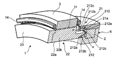
界磁コア6と回転子1との間には、第2エアギャップ212が形成されて、界磁コイル2と回転子1との間で磁束を受け渡している。第2エアギャップ212は、界磁コア6と回転子1との間で回転子1の回転軸7の軸方向の変速機側の端面と界磁コア6のエンジン側の端面において、回転軸7の軸方向に対して傾斜角度αで傾斜する隙間である。
より詳しくは、第2エアギャップ212は、図13Aに示すように、界磁コア6と回転子1の第2磁極22との間で回転子1の回転軸7の軸方向の変速機側の端面と界磁コア6のエンジン側の端面と、界磁コア6と回転子1の第1磁極21との間で回転子1の回転軸7の軸方向の変速機側の端面と界磁コア6のエンジン側の端面とに、それぞれ形成されている。
まず、界磁コア6と回転子1の第2磁極22との間で回転子1の回転軸7の軸方向の変速機側の端面と界磁コア6のエンジン側の端面において、第2エアギャップ212は、回転軸7の中心側から、回転軸7の軸方向に対して垂直な隙間の第1垂直部212aと、回転軸7の軸方向に対して傾斜角度αで傾斜した隙間の傾斜部212bと、回転軸7の軸方向に対して垂直な隙間の第2垂直部212cとで構成されている。第1垂直部212aと傾斜部212bと第2垂直部212cとは連続して接続されている。傾斜部212bの傾斜方向としては、径方向の内側から外側に向かうに従い、徐々にエンジン側から変速機側に向かうように傾斜している。第1垂直部212aと傾斜部212bと第2垂直部212cとのそれぞれの隙間はほぼ同じである。
また、界磁コア6と回転子1の第1磁極21との間で回転子1の回転軸7の軸方向の変速機側の端面と界磁コア6のエンジン側の端面において、第2エアギャップ212は、回転軸7の中心側から、回転軸7の軸方向に対して垂直な隙間の第1垂直部212aと、回転軸7の軸方向に対して傾斜角度αで傾斜した隙間の傾斜部212bと、回転軸7の軸方向に対して垂直な隙間の第2垂直部212cとで構成されている。第1垂直部212aと傾斜部212bと第2垂直部212cとは連続して接続されている。傾斜部212bの傾斜方向としては、径方向の内側から外側に向かうに従い、第2磁極22側の第2エアギャップ212とは逆に、徐々に変速機側からエンジン側に向かうように傾斜している。第1垂直部212aと傾斜部212bと第2垂直部212cとのそれぞれの隙間はほぼ同じである。
結局、第1磁極21側の第2エアギャップ212の傾斜方向と、第2磁極22側の第2エアギャップ212の傾斜方向とを合わせると、図12Bに示すように、エンジン側から変速機側に向けて尖った大略V字形状を形成するように配置されている。この大略V字形状は一例であり、逆向きの大略V字形状でもよいし、又は、平行な形状でもよい。すなわち、第1磁極21側の第2エアギャップ212の傾斜方向と、第2磁極22側の第2エアギャップ212の傾斜方向とは、それぞれ、任意の方向でよく、かつ、傾斜角度も任意である。一例として、両者の傾斜方向を同じにすれば、磁束と軸方向力のバランスの観点からは好ましい。
第2エアギャップ212としては、少なくとも傾斜部212bを備えていればよく、垂直部212a又は212cは1つ又は2つ程度備えればよい。
ここで、第2エアギャップ212を、このように傾斜させる理由について説明する。
回転子1と界磁コイル2との間の第2エアギャップ212を回転軸7の軸方向の垂直面として形成してしまうと、エアギャップ断面積が少ないため磁気抵抗が高くなり、ロータ界磁に必要な界磁電流が高くなってしまう可能性がある。また、第2エアギャップ212が回転軸7の軸方向に垂直に形成すると、軸方向に電磁吸引力が発生し、発進装置4を保持する軸受(図示せず)に大きなアキシャル力が作用する可能性がある。
特に、第2エアギャップ212が回転軸7の軸方向に対し垂直に形成されている場合、断面において、第2エアギャップ212の有効磁路幅は、界磁コア6の厚み及び磁極厚みと同等である。また、界磁コア6を励磁した際、界磁コア6と回転子1との間には電磁吸引力が作用するが、第2エアギャップ212が回転軸7の軸方向に対して垂直に形成されていると、電磁吸引力は全てアキシャル力として作用する。
これに対して、第3実施形態のように、第2エアギャップ212を回転軸7の軸方向に対して傾斜して形成すれば、垂直に形成されている場合と比較して、第2エアギャップ212の有効磁路幅を拡大する事ができるとともに、電磁吸引力をアキシャル力だけでなくラジアル力にも分散する事で、アキシャル力を減少させる事ができる。
ここで、図13Cに、垂直に形成されている場合の磁束と電磁力を棒グラフ91で示し、第3実施形態のように斜めに形成されている場合の磁束と電磁力とを棒グラフ92で示す。ここでは、垂直に形成されている場合の磁束と電磁力とのそれぞれの倍率を1としたときの、第3実施形態のように斜めに形成されている場合の磁束と電磁力との倍率1.04と0.76とを表示している。第3実施形態のように斜めに形成されている場合のほうが、垂直に形成されている場合よりも、有効磁路幅の拡大により磁束が大きくなり、ラジアル力への分散により電磁吸引力すなわち電磁力が小さくなっていることがわかる。
よって、軸方向の電磁吸引力を減らして、軸受にかかるアキシャル力を低減する事ができる。その結果、ドラッグトルクを低減し、車両燃費を向上する事ができる。
また、第2エアギャップ212を傾斜させることにより第2エアギャップ212の断面積を拡大すれば、磁気抵抗を下げ、界磁電流を低減する事ができる。その結果、回転電機10の効率が向上し、車両燃費をさらに向上する事ができる。
前記したような様々な効果を確実に奏するためには、各傾斜部212bの傾斜角度αは、一例として、回転軸7の軸方向に対して10度から25度の範囲とする。
なお、前記した傾斜部212bの傾斜方向としては、第1磁極21と第2磁極22とで逆になっていてもよい。すなわち、第2磁極22側の傾斜部212bでは、径方向の内側から外側に向かうに従い、徐々に変速機側からエンジン側に向かうように傾斜する一方、第1磁極21側の傾斜部212bでは、径方向の内側から外側に向かうに従い、徐々にエンジン側から変速機側に向かうように傾斜してもよい。
また、図12Cに示すように、第2エアギャップ212は、垂直部212a,212cが無く、傾斜部212bのみで構成するようにしてもよい。
よって、界磁コイル2は、回転子1に対して、第2エアギャップ212を介して回転軸7の軸方向にずらされて並列して配置されている。
なお、第3実施形態において、先の第1実施形態の図3~図6に対応する構成は、第1実施形態の構成と同一であるため、それらの説明及び図示を省略する。
以上のように構成された回転電機10においては、界磁コイル2が通電されると、界磁コイル磁束15が発生する。界磁コイル磁束15は、界磁コア6から、第2エアギャップ212と回転子1の第1磁極21と第1エアギャップ11と固定子3と第1エアギャップ11と回転子1の第2磁極22と第2エアギャップ212とを介して、界磁コア6に戻ることにより構成されている。このとき、例えば、直流電流が界磁コイル2に通電されれば、界磁コイル磁束15を発生させ、第1磁極21と第2磁極22とは、それぞれ、例えばN極とS極とにそれぞれ磁化されている。
このような回転電機10において、まず、回転電機10をスタータとして始動機能を発揮させる場合について説明する。エンジン8の始動指令に基づき、図示しないインバータを駆動して固定子3に三相交流電流を流して固定子3を磁化するとともに、界磁コイル2に電流を流す。界磁コイル2に電流を流して、回転子1の第1磁極21と第2磁極22とを励磁する。この結果、回転子1が固定子3に対して回転を開始するとともに、固定子3において誘起電圧を有する起電力が発生する。
その後、誘起電圧は回転子1の回転速度に応じて増加し、回転速度がエンジン8のアイドリングに対応するアイドリング回転速度より低い初爆の回転速度に到達したとき、インバータの駆動を停止し、以後、所定の誘起電圧(要求電圧)を保持するように、自動的に発電モード、すなわち、回転電機10を発電機として発電機能を発揮させる場合に移行する。
この発電モードでは、界磁コイル2を励磁し続けるとき、誘起電圧が所定の誘起電圧で一定になるように、励磁電流を調整する。励磁電流を調整するとき、まず、界磁コイル2の磁化力が一定となるように励磁電流を調整する。これは、界磁コイル2が、あたかも永久磁石として機能することを意味している。このように、あたかも永久磁石が配置されたかのような状態で、回転子1が回転すると、回転電機10は発電機として機能することになる。
この結果、エンジン8と回転電機10とを連結することで、エンジン始動を可能とし、かつ走行中はジェネレータ(発電機)として機能する事ができる。
前記第3実施形態によれば、自動車発進装置4の外周に配置するブラシレス巻線界磁型回転電機10において、界磁コイル2と回転子1との間の第2エアギャップ212を回転軸7に対して傾斜して配置している。特に、回転子1の第1磁極21を円環状の部材でかつ多数の爪部21bを有する形状とし、第2磁極22を円環状の部材でかつ多数の凸部22bを有する形状とし、これらの第1及び第2磁極21,22を周方向に交互に配置した上で、第1及び第2磁極21,22を非磁性体の磁極保持部材23で保持する構造としている。このような構成によれば、以下のような効果を奏することができる。
まず、第3実施形態に対する比較例であって図14の(b)に従来の特許文献1,2の組み合わせ例として示すように、発進装置104の径方向外側に回転電機110を配置して、ケース105と発進装置104との間のスペースで径方向の外から内向きに、固定子103と、回転子101と、界磁コイル102との3つの部材を配置する場合、界磁コイル102の磁束を大きくしようとしてコイルの巻数が多くすると、径方向の厚みが大きくなり、当該スペースには入らず、磁束を大きくすることができなかった。
これに対して、第3実施形態では、図14の(a)に示すように、固定子3及び回転子1に対して界磁コイル2を回転軸7の軸方向にずらせて並列配置するように構成している。このように構成すれば、発進装置4の径方向外側には、固定子3及び回転子1の2つの部材だけとなり、発進装置4の径方向外側に界磁コイル2の配置スペースは不要となる。このため、少なくとも界磁コイル2の配置スペース分だけ、発進装置4の外側の径方向寸法が小さくなる、又は、配置スペース分だけ固定子3又は回転子1の厚みが増加できるなど、有効に活用することができる。また、界磁コイル2を固定子3及び回転子1とは軸方向にずれた位置に配置するため、固定子3及び回転子1のスペースを考慮することなく、界磁コイル2の径方向の厚みを大きくして、界磁コイル2の磁束を大きくすることができる。よって、設計の自由度を大きくすることができる。
また、図14の(b)のように、径方向の外から内向きに固定子103、回転子101、界磁コイル102を配置する場合、回転子101と界磁コイル102との隙間寸法は、回転子101の遠心力による膨らみなどの厚みの変化を考慮して、設計する必要があり、一般的には必要な寸法よりも大きく設計する必要があった。
これに対して、図14の(a)のように、固定子3及び回転子1に対して界磁コイル2を軸方向にずらせて配置して、界磁コイル2と回転子1との隙間を軸方向に対して傾斜して第2エアギャップ212とすれば、前記したように回転電機10の効率向上とアキシャル力の低減とを図ることができる。
また、図14の(b)のような径方向の配置では、回転側の回転子101と固定側の界磁コイル102との同心性(同心位置の位置調整)が厳しかったが、図14の(a)のように軸方向にずらせて配置すれば、回転側の回転子1と固定側の界磁コイル2との同心性を、図14の(b)の構成ほど厳しく調整する必要がない。
また、図14の(a)の構成では、界磁コイル2を回転子1の軸方向のエンジン側又は変速機側のいずれかのスペースに配置可能とすることにより、当該スペースを有効活用することができる。
また、回転電機10の回転子1をエンジン8の出力軸(回転軸)7と同期回転する同期回転部材である発進装置4に連結するとともに、エンジン8の出力軸の中心軸を回転子1の回転軸となるように回転電機10を配置しているので、冷間時でも、回転電機10の回転駆動力をエンジン8に確実に伝達でき、冷間時にエンジン8を確実に始動させることができる。
従って、第3実施形態によれば、ケース5の内周側でかつ発進装置4の外周側という狭小なる空間に、回転子1以外に、固定子3又は界磁コイル2のいずれか一方のみを配置させることにより、2つの部材を回転軸7の同軸異径上に配置するだけでよいため、設計自由度が大きくなり、回転電機10の出力性能を向上させることができる。さらに、第2エアギャップ212は、回転子1の回転軸7の軸方向の一方の端面において、回転軸7の軸方向に対して傾斜した隙間である傾斜部212bを有するので、回転電機10の効率向上とアキシャル力の低減とを図ることができる。
(第4実施形態)
図15~図17に示すように、本発明の第4実施形態として、第3実施形態の構成において、回転子1の内部に永久磁石27を配置した構造としてもよい。
図15~図17に示すように、本発明の第4実施形態として、第3実施形態の構成において、回転子1の内部に永久磁石27を配置した構造としてもよい。
より具体的には、第1磁極21の各爪部21bと周方向の同一位置で、かつ、第1磁極21の各爪部21bの内径側でかつ第2磁極22の第2円環部22aの外径側に、各爪部21bの内周面と第2円環部22aの外周面との間で例えば矩形板状の永久磁石27を挟持するように備える。この配置により、図16に示すように、永久磁石27の磁石磁束28が第1磁極21の各爪部21bと第2磁極22の凸部22bとの間に形成されるようにしている。
永久磁石27は、ネオジムを主原料とした磁石又はフェライトを主原料とした磁石である。具体的には、永久磁石27としては、例えば、SmCo磁石、AlNiCo磁石、又は、ネオジムボンド磁石など、多様な種類の永久磁石を使用することができる。永久磁石27は、各爪部21bの内側全面又はその一部に配置している。
このように構成することで、界磁コイル2により回転子1に発生する磁束に加えて永久磁石27の磁石磁束28を利用することで、出力性能を向上させることができる。また、永久磁石27を爪部21bで抑えて保持することにより、永久磁石27の遠心力に対する強度を補強することができ、遠心力による永久磁石27の変形を防止でき、高回転時の遠心強度を向上する事ができる。
なお、前記様々な実施形態又は変形例のうちの任意の実施形態又は変形例を適宜組み合わせることにより、それぞれの有する効果を奏するようにすることができる。また、実施形態同士の組み合わせ又は実施例同士の組み合わせ又は実施形態と実施例との組み合わせが可能であると共に、異なる実施形態又は実施例の中の特徴同士の組み合わせも可能である。
本発明は、添付図面を参照しながら実施形態に関連して充分に記載されているが、この技術の熟練した人々にとっては種々の変形や修正は明白である。そのような変形や修正は、添付した請求の範囲による本発明の範囲から外れない限りにおいて、その中に含まれると理解されるべきである。
本発明の前記態様にかかる回転電機は、設計自由度が大きくなり、出力性能を向上させることができて、車両のオルタネータ及びスタータモータの持つ発電機能及びエンジン始動機能を統合する回転電機付き動力伝達装置等として有用である。
1 回転子
2 界磁コイル
3 固定子
4 発進装置
5 ケース
6 界磁コア
7 回転軸
8 エンジン
9 変速機
10 ブラシレス巻線界磁型回転電機
11 第1エアギャップ
12 第2エアギャップ
14 交流コイル
15 界磁コイル磁束
16 径方向隙間
17 周方向隙間
19 軸方向隙間
21 第1磁極
21a 第1円環部
21b 爪部
21c 第1先端係止部
22 第2磁極
22a 第2円環部
22b 凸部
22c 第2先端係止部
22d はめ込み部
23 磁極保持部材
23a 嵌合部
27 永久磁石
28 永久磁石磁束
89 固定子のエンジン側にずらせて配置した界磁コイルの領域
91,92 棒グラフ
212 第2エアギャップ
212a,212c 垂直部
212b 傾斜部
α 傾斜角度
2 界磁コイル
3 固定子
4 発進装置
5 ケース
6 界磁コア
7 回転軸
8 エンジン
9 変速機
10 ブラシレス巻線界磁型回転電機
11 第1エアギャップ
12 第2エアギャップ
14 交流コイル
15 界磁コイル磁束
16 径方向隙間
17 周方向隙間
19 軸方向隙間
21 第1磁極
21a 第1円環部
21b 爪部
21c 第1先端係止部
22 第2磁極
22a 第2円環部
22b 凸部
22c 第2先端係止部
22d はめ込み部
23 磁極保持部材
23a 嵌合部
27 永久磁石
28 永久磁石磁束
89 固定子のエンジン側にずらせて配置した界磁コイルの領域
91,92 棒グラフ
212 第2エアギャップ
212a,212c 垂直部
212b 傾斜部
α 傾斜角度
Claims (14)
- 回転軸沿いのエンジンと変速機との間に配置され、発進装置を内包するケースと前記発進装置との間に位置するブラシレス巻線界磁型回転電機であって、
前記ケースに保持され、交流電流により回転磁界を発生する交流コイルを内部に備えた固定子と、
前記ケースに保持され、直流電流により励磁する界磁コイルを内部に備えた界磁コアと、
前記発進装置の外周に配置され、前記固定子及び前記界磁コイルに対し前記回転軸周りに回転自在に保持される回転子と、
前記固定子と前記回転子との間に形成されて前記固定子と前記回転子との間で磁束を受け渡す第1エアギャップと、
前記界磁コアと前記回転子との間に形成されて前記界磁コアと前記回転子との間で磁束を受け渡す第2エアギャップとを備えて、
前記第2エアギャップは、前記回転子の前記回転軸の軸方向の一方の端面において、前記回転軸の前記軸方向とは交差する方向沿いに延在する隙間である、回転電機。 - 前記第2エアギャップは、前記回転子の前記回転軸の前記軸方向の一方の端面において、前記回転軸の前記軸方向とは垂直な径方向沿いに延在する隙間である、請求項1に記載の回転電機。
- 前記第2エアギャップは、前記回転子の前記回転軸の前記軸方向の前記一方の端面において、前記回転軸の前記軸方向に対して傾斜した隙間である傾斜部を有する、請求項1に記載の回転電機。
- 前記第2エアギャップは、前記回転軸の前記軸方向に対して傾斜した前記傾斜部と、前記傾斜部に続いて形成されかつ前記回転軸に対し垂直な垂直部とを備えている、請求項3に記載の回転電機。
- 前記傾斜部の傾斜角度は、前記回転軸の前記軸方向に対して10度から25度の範囲である、請求項3又は4に記載の回転電機。
- 前記界磁コアの前記界磁コイルは、前記回転子に対して、前記第2エアギャップを介して前記回転軸の前記軸方向に並列して配置される、請求項1~5のいずれか1つに記載の回転電機。
- 前記第1エアギャップは、前記回転子の前記回転軸の前記軸方向の前記一方の端面において、前記回転軸の前記軸方向沿いに延在する隙間である、請求項1~6のいずれか1つに記載の回転電機。
- 前記回転子は、
第1円環部から前記回転軸の前記軸方向に突き出た複数の爪部を持つ第1磁極と、
前記第1円環部の内側に径方向隙間をあけて配置され、前記第1円環部と部分的に重なるように配置された第2円環部の外周面に径方向に突出しかつ周方向には周方向隙間を有して配置された複数の凸部を持つ第2磁極と、
前記第1磁極の前記爪部と前記第2磁極の前記凸部とが嵌合固定される嵌合部を有する円環状の磁極保持部材とで構成され、
前記第1磁極と前記第2磁極とは、前記第1磁極の前記爪部が前記第2磁極の前記凸部と前記凸部との間の前記隙間内に挿入されて、前記第1磁極の前記爪部と、前記第2磁極の前記凸部とが周方向に交互に配置され、
前記第1磁極と前記第2磁極とは、お互いに接触することなく、前記磁極保持部材に嵌合固定される、請求項1~7のいずれか1つに記載の回転電機。 - 前記第1磁極の前記爪部の第1先端係止部は、前記磁極保持部材の外周側に配置された前記嵌合部に嵌合されて、径方向に対して固定的に保持されるとともに、前記第2磁極の第2先端係止部は、前記磁極保持部材の前記嵌合部に嵌合されて、径方向に対して固定的に保持される、
請求項8に記載の回転電機。 - 前記磁極保持部材は、非磁性体である、請求項8又は9に記載の回転電機。
- 前記第1磁極と前記第2磁極とは、それぞれ、軟磁性体である、請求項8~10のいずれか1つに記載の回転電機。
- 前記第1磁極の前記爪部と周方向の同一位置であって、前記第1磁極の内径側でかつ前記第2磁極の前記第2円環部の外径側に永久磁石をさらに備える、請求項8~11のいずれか1つに記載の回転電機。
- 前記永久磁石は、ネオジムを主原料とした磁石である、請求項12に記載の回転電機。
- 前記永久磁石は、フェライトを主原料とした磁石である、請求項12に記載の回転電機。
Priority Applications (4)
| Application Number | Priority Date | Filing Date | Title |
|---|---|---|---|
| US16/480,408 US10985638B2 (en) | 2017-01-27 | 2018-01-26 | Rotary electric machine |
| JP2018507040A JP7195923B2 (ja) | 2017-01-27 | 2018-01-26 | 回転電機 |
| CN201880008601.3A CN110235343B (zh) | 2017-01-27 | 2018-01-26 | 旋转电机 |
| EP18744762.8A EP3562010A4 (en) | 2017-01-27 | 2018-01-26 | ELECTRIC LATHE |
Applications Claiming Priority (4)
| Application Number | Priority Date | Filing Date | Title |
|---|---|---|---|
| JP2017013495 | 2017-01-27 | ||
| JP2017-013495 | 2017-01-27 | ||
| JP2017-248191 | 2017-12-25 | ||
| JP2017248191 | 2017-12-25 |
Publications (1)
| Publication Number | Publication Date |
|---|---|
| WO2018139561A1 true WO2018139561A1 (ja) | 2018-08-02 |
Family
ID=62978583
Family Applications (1)
| Application Number | Title | Priority Date | Filing Date |
|---|---|---|---|
| PCT/JP2018/002372 Ceased WO2018139561A1 (ja) | 2017-01-27 | 2018-01-26 | 回転電機 |
Country Status (5)
| Country | Link |
|---|---|
| US (1) | US10985638B2 (ja) |
| EP (1) | EP3562010A4 (ja) |
| JP (1) | JP7195923B2 (ja) |
| CN (1) | CN110235343B (ja) |
| WO (1) | WO2018139561A1 (ja) |
Cited By (3)
| Publication number | Priority date | Publication date | Assignee | Title |
|---|---|---|---|---|
| US11050331B2 (en) | 2018-04-27 | 2021-06-29 | Exedy Corporation | Rotational electric machine |
| US11133732B2 (en) | 2018-04-27 | 2021-09-28 | Exedy Corporation | Rotational electric machine |
| US11146138B2 (en) | 2018-04-27 | 2021-10-12 | Exedy Corporation | Rotating electrical machine |
Citations (6)
| Publication number | Priority date | Publication date | Assignee | Title |
|---|---|---|---|---|
| JPH02159950A (ja) * | 1988-12-14 | 1990-06-20 | Tamagawa Seiki Co Ltd | 発電機 |
| JP3445492B2 (ja) | 1998-05-25 | 2003-09-08 | 三菱電機株式会社 | クローポール型ブラシレス発電機 |
| JP2004266965A (ja) * | 2003-03-04 | 2004-09-24 | Mitsubishi Electric Corp | 回転電機の回転子 |
| JP2010516558A (ja) | 2007-01-29 | 2010-05-20 | ルーク ラメレン ウント クツプルングスバウ ベタイリグングス コマンディートゲゼルシャフト | ハイブリッド使用のための湿式の発進クラッチを備えるパワートレーン |
| WO2012067223A1 (ja) * | 2010-11-19 | 2012-05-24 | アスモ 株式会社 | ロータ及びモータ |
| JP2013212037A (ja) * | 2012-02-29 | 2013-10-10 | Aisin Aw Co Ltd | ハイブリッド励磁式回転電機 |
Family Cites Families (9)
| Publication number | Priority date | Publication date | Assignee | Title |
|---|---|---|---|---|
| DE1245483B (de) | 1960-07-08 | 1967-07-27 | Licentia Gmbh | Elektrische Klauenpolmaschine mit Wechselpolen |
| JPS5236710A (en) | 1975-09-18 | 1977-03-22 | Toyo Electric Mfg Co Ltd | Brushless rotary electric machine |
| FR2762722B1 (fr) | 1997-04-23 | 1999-07-30 | Centre Nat Rech Scient | Machine electrique a double excitation perfectionnee |
| US6794790B2 (en) | 2002-03-20 | 2004-09-21 | Denso Corporation | Rotary electric machine |
| US6972504B1 (en) * | 2004-05-18 | 2005-12-06 | Ut-Battelle Llc | Permanent magnet machine and method with reluctance poles for high strength undiffused brushless operation |
| JP4682729B2 (ja) | 2005-07-22 | 2011-05-11 | マツダ株式会社 | スイッチドリラクタンスモータ |
| US7622840B2 (en) | 2005-07-22 | 2009-11-24 | Mazda Motor Corporation | Electric machine and method of using electric machine |
| JP4519928B2 (ja) | 2008-06-02 | 2010-08-04 | 株式会社日本自動車部品総合研究所 | ハイブリッド励磁型同期機 |
| JP2011067048A (ja) | 2009-09-18 | 2011-03-31 | Sanyo Electric Co Ltd | 永久磁石同期モータ |
-
2018
- 2018-01-26 JP JP2018507040A patent/JP7195923B2/ja active Active
- 2018-01-26 EP EP18744762.8A patent/EP3562010A4/en not_active Withdrawn
- 2018-01-26 US US16/480,408 patent/US10985638B2/en active Active
- 2018-01-26 CN CN201880008601.3A patent/CN110235343B/zh active Active
- 2018-01-26 WO PCT/JP2018/002372 patent/WO2018139561A1/ja not_active Ceased
Patent Citations (6)
| Publication number | Priority date | Publication date | Assignee | Title |
|---|---|---|---|---|
| JPH02159950A (ja) * | 1988-12-14 | 1990-06-20 | Tamagawa Seiki Co Ltd | 発電機 |
| JP3445492B2 (ja) | 1998-05-25 | 2003-09-08 | 三菱電機株式会社 | クローポール型ブラシレス発電機 |
| JP2004266965A (ja) * | 2003-03-04 | 2004-09-24 | Mitsubishi Electric Corp | 回転電機の回転子 |
| JP2010516558A (ja) | 2007-01-29 | 2010-05-20 | ルーク ラメレン ウント クツプルングスバウ ベタイリグングス コマンディートゲゼルシャフト | ハイブリッド使用のための湿式の発進クラッチを備えるパワートレーン |
| WO2012067223A1 (ja) * | 2010-11-19 | 2012-05-24 | アスモ 株式会社 | ロータ及びモータ |
| JP2013212037A (ja) * | 2012-02-29 | 2013-10-10 | Aisin Aw Co Ltd | ハイブリッド励磁式回転電機 |
Non-Patent Citations (1)
| Title |
|---|
| See also references of EP3562010A4 |
Cited By (3)
| Publication number | Priority date | Publication date | Assignee | Title |
|---|---|---|---|---|
| US11050331B2 (en) | 2018-04-27 | 2021-06-29 | Exedy Corporation | Rotational electric machine |
| US11133732B2 (en) | 2018-04-27 | 2021-09-28 | Exedy Corporation | Rotational electric machine |
| US11146138B2 (en) | 2018-04-27 | 2021-10-12 | Exedy Corporation | Rotating electrical machine |
Also Published As
| Publication number | Publication date |
|---|---|
| JPWO2018139561A1 (ja) | 2019-11-14 |
| US20200161952A1 (en) | 2020-05-21 |
| US10985638B2 (en) | 2021-04-20 |
| EP3562010A4 (en) | 2020-07-29 |
| JP7195923B2 (ja) | 2022-12-26 |
| EP3562010A1 (en) | 2019-10-30 |
| CN110235343A (zh) | 2019-09-13 |
| CN110235343B (zh) | 2021-07-16 |
Similar Documents
| Publication | Publication Date | Title |
|---|---|---|
| JP7195923B2 (ja) | 回転電機 | |
| WO2017126297A1 (ja) | 回転電機 | |
| CN110417156B (zh) | 旋转电机 | |
| CN110417221B (zh) | 旋转电机 | |
| CN110417222B (zh) | 旋转电机 | |
| EP3561290B1 (en) | Rotational electric machine | |
| JP7141250B2 (ja) | 回転電機 | |
| JP7215917B2 (ja) | 回転電機 | |
| JP7141249B2 (ja) | 回転電機 | |
| US20220337143A1 (en) | Rotor of rotary electric machine | |
| JP4680221B2 (ja) | 回転電機 | |
| CN110233557A (zh) | 旋转电机 |
Legal Events
| Date | Code | Title | Description |
|---|---|---|---|
| ENP | Entry into the national phase |
Ref document number: 2018507040 Country of ref document: JP Kind code of ref document: A |
|
| 121 | Ep: the epo has been informed by wipo that ep was designated in this application |
Ref document number: 18744762 Country of ref document: EP Kind code of ref document: A1 |
|
| ENP | Entry into the national phase |
Ref document number: 2018744762 Country of ref document: EP Effective date: 20190722 |
|
| NENP | Non-entry into the national phase |
Ref country code: DE |