WO2018139678A1 - 梱包具 - Google Patents
梱包具 Download PDFInfo
- Publication number
- WO2018139678A1 WO2018139678A1 PCT/JP2018/003053 JP2018003053W WO2018139678A1 WO 2018139678 A1 WO2018139678 A1 WO 2018139678A1 JP 2018003053 W JP2018003053 W JP 2018003053W WO 2018139678 A1 WO2018139678 A1 WO 2018139678A1
- Authority
- WO
- WIPO (PCT)
- Prior art keywords
- container
- films
- pair
- container half
- packing tool
- Prior art date
- Legal status (The legal status is an assumption and is not a legal conclusion. Google has not performed a legal analysis and makes no representation as to the accuracy of the status listed.)
- Ceased
Links
Images



Classifications
-
- B—PERFORMING OPERATIONS; TRANSPORTING
- B64—AIRCRAFT; AVIATION; COSMONAUTICS
- B64D—EQUIPMENT FOR FITTING IN OR TO AIRCRAFT; FLIGHT SUITS; PARACHUTES; ARRANGEMENT OR MOUNTING OF POWER PLANTS OR PROPULSION TRANSMISSIONS IN AIRCRAFT
- B64D1/00—Dropping, ejecting, releasing or receiving articles, liquids, or the like, in flight
- B64D1/02—Dropping, ejecting, or releasing articles
- B64D1/08—Dropping, ejecting, or releasing articles the articles being load-carrying devices
-
- B—PERFORMING OPERATIONS; TRANSPORTING
- B64—AIRCRAFT; AVIATION; COSMONAUTICS
- B64D—EQUIPMENT FOR FITTING IN OR TO AIRCRAFT; FLIGHT SUITS; PARACHUTES; ARRANGEMENT OR MOUNTING OF POWER PLANTS OR PROPULSION TRANSMISSIONS IN AIRCRAFT
- B64D1/00—Dropping, ejecting, releasing or receiving articles, liquids, or the like, in flight
- B64D1/02—Dropping, ejecting, or releasing articles
- B64D1/08—Dropping, ejecting, or releasing articles the articles being load-carrying devices
- B64D1/14—Absorbing landing shocks
-
- B—PERFORMING OPERATIONS; TRANSPORTING
- B65—CONVEYING; PACKING; STORING; HANDLING THIN OR FILAMENTARY MATERIAL
- B65D—CONTAINERS FOR STORAGE OR TRANSPORT OF ARTICLES OR MATERIALS, e.g. BAGS, BARRELS, BOTTLES, BOXES, CANS, CARTONS, CRATES, DRUMS, JARS, TANKS, HOPPERS, FORWARDING CONTAINERS; ACCESSORIES, CLOSURES, OR FITTINGS THEREFOR; PACKAGING ELEMENTS; PACKAGES
- B65D81/00—Containers, packaging elements, or packages, for contents presenting particular transport or storage problems, or adapted to be used for non-packaging purposes after removal of contents
- B65D81/02—Containers, packaging elements, or packages, for contents presenting particular transport or storage problems, or adapted to be used for non-packaging purposes after removal of contents specially adapted to protect contents from mechanical damage
- B65D81/022—Containers made of shock-absorbing material
-
- B—PERFORMING OPERATIONS; TRANSPORTING
- B65—CONVEYING; PACKING; STORING; HANDLING THIN OR FILAMENTARY MATERIAL
- B65D—CONTAINERS FOR STORAGE OR TRANSPORT OF ARTICLES OR MATERIALS, e.g. BAGS, BARRELS, BOTTLES, BOXES, CANS, CARTONS, CRATES, DRUMS, JARS, TANKS, HOPPERS, FORWARDING CONTAINERS; ACCESSORIES, CLOSURES, OR FITTINGS THEREFOR; PACKAGING ELEMENTS; PACKAGES
- B65D81/00—Containers, packaging elements, or packages, for contents presenting particular transport or storage problems, or adapted to be used for non-packaging purposes after removal of contents
- B65D81/02—Containers, packaging elements, or packages, for contents presenting particular transport or storage problems, or adapted to be used for non-packaging purposes after removal of contents specially adapted to protect contents from mechanical damage
- B65D81/05—Containers, packaging elements, or packages, for contents presenting particular transport or storage problems, or adapted to be used for non-packaging purposes after removal of contents specially adapted to protect contents from mechanical damage maintaining contents at spaced relation from package walls, or from other contents
- B65D81/07—Containers, packaging elements, or packages, for contents presenting particular transport or storage problems, or adapted to be used for non-packaging purposes after removal of contents specially adapted to protect contents from mechanical damage maintaining contents at spaced relation from package walls, or from other contents using resilient suspension means
- B65D81/075—Containers, packaging elements, or packages, for contents presenting particular transport or storage problems, or adapted to be used for non-packaging purposes after removal of contents specially adapted to protect contents from mechanical damage maintaining contents at spaced relation from package walls, or from other contents using resilient suspension means the contents being located between two membranes stretched between opposed sides of the package
Definitions
- the present invention relates to a packaging tool.
- the package when the package is dropped to the ground and delivered using an unmanned aerial vehicle, it is preferable to further improve the shock resistance performance of the package.
- a package in one aspect of the invention, may comprise a container.
- the package may comprise at least one pair of films. At least one pair of films may be stretchable.
- the packaging tool may comprise a fixed part. The fixing portion may be oppositely fixed in a stretched state of at least a pair of films in the internal space of the container.
- the packing tool may hold the object to be packed between the pair of films.
- the container may comprise a substrate.
- the substrate may be formed of a foamed synthetic resin.
- the container may be provided with a coating layer.
- the coating layer may be formed of polyurea resin.
- the base material of the foamed synthetic resin may be provided with an internal space.
- the coating layer of polyurea resin may cover the outer surface of the substrate and the inner surface of the inner space.
- the container may be in the shape of a rugby ball.
- the first container half and the second container half may be combined to form an internal space.
- the first container half and the second container half may be engaged by closing the open ends of the first container half and the second container half so as to abut each other.
- the pair of films may have a first film and a second film.
- the first film and the second film may be fixed in a stretched state along the open ends of the first container half and the second container half, respectively.
- a parachute portion may be provided at one end of the container.
- the parachute portion may reduce the dropping speed of the packing tool when the packing tool falls from above.
- the other end opposite to the one end of the container may be thicker than the one end.
- the other end opposite the one end of the container may have a tapered shape.
- FIG. 1 It is a sectional view showing an example of packing tool 100 in a 1st embodiment of the present invention. It is a figure which shows the state which opened the packing tool 100. As shown in FIG. It is a figure showing packing device 100 in the state where parachute part 170 was opened. It is a figure which shows the other example of the packing tool.
- FIG. 1 is a cross-sectional view showing an example of a packaging tool 100 according to a first embodiment of the present invention.
- FIG. 2 is a figure which shows the state which opened the packaging tool 100.
- the packing tool 100 packs the item to be packed 102.
- the packaging tool 100 may be transported by air, dropped from above, and delivered to a destination.
- the item to be packaged 102 is not particularly limited, it is suitable for airborne transport of pharmaceuticals such as various vaccines.
- the package 100 comprises a first container half 110, a second container half 120, and at least one pair of films 140.
- the containers (110, 120) are formed by closing the open ends of the first container half 110 and the second container half 120 so that they abut.
- the first container half 110 and the second container half 120 are combined to form an internal space 130.
- the first container half 110 and the second container half 120 may not necessarily have the same size.
- the container (110, 120) of this example has a spheroidal shape (spheroid shape) in which the major axis is the rotation axis as a whole. That is, the container (110, 120) is in the shape of a rugby ball.
- the container (110, 120) having a rugby ball shape stabilizes the dropping posture when the packaging tool 100 is air-lifted and freely dropped at the time of delivery, and is less susceptible to the influence of wind.
- the size of the container (110, 120) is not limited, the length of the major axis may be 0.5 m or more and 10 m or less.
- the container (110, 120) may be divided into a first container half 110 and a second container half 120 in a cutting plane along the major axis.
- the first container half 110 has a substrate 112, an outer surface coating layer 114, and an inner surface coating layer 116.
- the substrate 112 is formed of a foamed synthetic resin.
- the synthetic resin which forms the base material 112 as an example is a high molecular compound.
- the synthetic resin forming the substrate 112 is formed of one or more materials selected from polystyrene, polyethylene, polypropylene and polyurethane. Foam synthetic resin refers to what disperse
- the substrate 112 is formed of expanded polystyrene (expanded polystyrene).
- the outer surface coating layer 114 and the inner surface coating layer 116 are coating layers of polyurea resin.
- the outer surface coating layer 114 covers the outer surface 117 of the substrate 112.
- the inner surface coating layer 116 covers the inner surface 118 of the substrate 112.
- the inner surface 118 refers to a surface exposed to the inner space 130.
- the coating layers (114, 116) may be formed on the entire surface of the substrate 112. In the example shown in FIGS. 1 and 2, the coating layers (114, 116) do not cover the open end, but unlike in the case of FIGS. 1 and 2, the coating layers (114, 116)
- the open end may be covered as well as the outer surface 117 and the inner surface 118 of the The open end refers to the surface between the outer surface 117 and the inner surface 118 of the substrate 112.
- the thickness of the coating layer (114, 116) is smaller than the thickness of the substrate 112.
- the thickness of the substrate 112 is 3 cm or more, and the thickness of the coating layer (114, 116) is 5 mm or less.
- the second container half 120 has a substrate 122, an outer surface coating layer 124, and an inner surface coating layer 126. These structures may be similar to the structures of the substrate 112, the outer surface coating layer 114, and the inner surface coating layer 116 in the first container half 110. Therefore, the repeated description is omitted.
- the pair of films 140 includes a first film 140a and a second film 140b.
- the first film 140 a is fixed in a stretched state along the open end of the first container half 110.
- the second film 140 b is fixed in a stretched state along the open end of the second container half 120.
- the first film 140a and the second film 140b are oppositely fixed in a stretched state of the first film 140a and the second film 140b in the internal space 130 formed by the containers (110, 120).
- the packaging tool 100 includes a fixing portion 142.
- the first film 140a and the second film 140b are fixed to the open end of the container (110, 120) by the fixing portion 142, respectively.
- the fixing portion 142 may be an adhesive, and may sandwich and fix the first film 140a and the second film 140b.
- the structure of the fixing portion 142 is not limited. Multiple pairs of films 140 may be stretched parallel to one another.
- the first film 140a and the second film 140b are films having stretchable elasticity.
- the first film 140a and the second film 140b are made of, for example, plastic films such as polyurethane, polyethylene, and polypropylene.
- the thickness of the first film 140a and the second film 140b may be 80 ⁇ m or more and 100 ⁇ m or less.
- the packing tool 100 of the present example holds the to-be-packaged object 102 between the pair of films 140 so as to be sandwiched.
- the to-be-packaged article 102 may be pinched between a pair of films 140 in the state further wrapped up with a buffer material.
- the buffer material may restrict the movement of the object to be packaged 102 between the pair of films 140.
- the package 100 may have a coupling 150.
- the coupling portion 150 couples the first container half 110 and the second container half 120.
- the coupling portion 150 in this example includes the protrusion 151, the support portion 153, and the clasp portion 155.
- One end of the protrusion 151 is embedded in the base 112 of the first container half 110, and the other end protrudes on the surface.
- One end of the projecting portion 151 in this example has a bent portion 152 which is bent in the base material 112 and is difficult to be removed.
- One end of the support portion 153 is embedded in the base material 122 of the second container half 120, and the clasp portion 155 is rotatably connected to the other end. The clasp portion 155 is fixed by fitting with the projection 151.
- One end of the support portion 153 has a bent portion 154 which is bent in the base material 122 and is difficult to remove.
- the coupling part 150 is not particularly limited as long as the coupling part 150 couples the first container half 110 and the second container half 120.
- FIG. 2 shows a state in which the first container half 110 and the second container half 120 are completely separated, but the present invention is not limited to this case, and the first container half 110 and the second container may be used.
- the half body 120 may be connected to open and close freely by a hinge portion. In this case, while the first container half 110 and the second container half 120 are closed, the first container half 110 and the second container half 120 are maintained in the closed state by the coupling portion 150. It may be fixed to
- a parachute portion for reducing the dropping speed of the packing tool 100 when the packing tool 100 is dropped from above.
- a parachute storage 160 is attached at one end along the minor axis of the spheroid.
- the other end located opposite to one end of the container (110, 120) may have a thicker thickness of the base 122 than the base 112 of the one end.
- the other end may have a thicker outer surface coating layer 124 than the outer surface coating layer 114 at one end.
- the thickness D1 of the other end may be thicker than the thickness D2 of the one end including the parachute portion.
- the other end opposite to the parachute part collides with the ground surface. Therefore, by making the thickness of the base material 122 on the other end side colliding with the ground surface thicker than the base material 112 on the one end side, impact resistance can be enhanced.
- the packing tool 100 may be provided with a GPS transmitter 158.
- the position where the GPS transmitter 158 is provided is not particularly limited.
- a GPS transmitter 158 is provided around the parachute housing 160.
- the GPS transmitter 158 uses GPS (Global Positioning System) to obtain position information regarding the current position of the package 100.
- the position information may be GPS position information.
- the GPS transmitter 158 transmits the acquired position information by wireless communication.
- the GPS transmitter 158 may transmit location information using radio waves of a mobile phone company or the like.
- the GPS transmitter 158 may be an automatic tracking type GPS transmitter that automatically acquires position information and transmits it automatically.
- the GPS transmitter 158 may transmit current position information.
- the GPS transmitter 158 may be configured to transmit position information. In this case, by transmitting the position information transmitted from the GPS transmitter 158, the delivery trader or the like can know that the packing tool 100 has landed safely.
- the transmitted GPS position information is acquired by the server and used.
- the delivery source, delivery destination, and / or delivery vendor can know the current position of the package.
- the packaging tool 100 falls by opening the parachute portion, it may fall off the destination due to the influence of wind.
- the position of the packing tool 100 can be grasped by the GPS transmitter 158, so that the luggage is not lost.
- the packing tool 100 may not have the GPS transmitter 158.
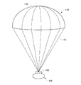
- FIG. 3 is a view showing the packaging tool 100 in a state in which the parachute portion 170 is opened.
- the parachute unit 170 is housed in the parachute storage unit 160.
- the parachute unit 170 moves out of the parachute storage unit 160 as a trigger when the packing tool 100 starts to fall and the predetermined time has elapsed or the predetermined speed is reached, and the automatic operation is performed automatically.
- the parachute unit 170 may be configured to be opened.
- the parachute portion 170 includes an umbrella body 172 and a plurality of string portions 174. One end of the cord portion 174 is coupled to the parachute storage 160, and the other end is coupled to the umbrella 172.
- the substrate (112, 122) is very lightweight since it is formed of a foamed synthetic resin. Also, since the coating layers (114, 116, 124, 126) are formed of a polyurea resin, they have high strength, excellent water resistance, and excellent impact resistance. Therefore, by coating the surface of the substrate (112, 122) with the coating layer (114, 116, 124, 126), the packaging tool 100 is ultra-lightweight and excellent in strength, water resistance, and impact resistance. Can provide
- the packaging tool 100 of this example is very lightweight, it can be easily transported and stored, and costs such as energy required for transportation can be reduced. Therefore, it can also contribute to environmental measures.
- the packaging tool 100 of this example is very lightweight, the burden imposed on the parachute portion 170 is less than in the case of the packaging tool made of metal. Therefore, since the parachute part 170 can be made small compared with the case of the packing tool made from metal, the installation space of the parachute storage part 160 can also be made small.
- the outer shape of the packaging tool 100 in this example is a spheroid. Therefore, it is possible to stabilize the falling posture when free falling at the time of delivery and to be less susceptible to the influence of the wind.
- the packaging tool 100 becomes less susceptible to the wind at least until the parachute portion 170 is opened.
- FIG. 4 is a view showing another example of the packaging tool 100.
- the containers (110, 120) are divided into the first container half 110 and the second container half 120 at the separation plane along the long axis of the spheroid. It had been.
- the packaging tool 100 of this example the containers (110, 120) are divided into the first container half 110 and the second container half 120 at the separation plane along the minor axis of the spheroid. Be done.
- the coupling unit 150 is not shown for the sake of simplicity of the description. Also in this example, the coupling portion 150 described in FIGS. 1 and 2 may be included.
- a parachute storage 160 is provided at one end of the container (110, 120).
- a parachute portion 170 is provided at one end of the container (110, 120) for reducing the dropping speed of the packaging tool 100 when the packaging tool 100 falls from above.
- the other end located opposite to the one end of the container (110, 120) has a thicker base 122 than the base 112 at one end.
- the other end may have a thicker outer surface coating layer 124 than the outer surface coating layer 114 at one end.
- the thickness D1 of the other end of the packaging tool 100 may be larger than the thickness D2 of one end including the parachute portion 170.
- the parachute portion 170 is provided at one end along the long axis in the container (110, 120).
- the other end opposite the one end of the container (110, 120) has a tapered shape. Therefore, even after the parachute portion 170 is opened, the other end portion having the tapered shape can be dropped in a posture in which the other end portion is in the vertical direction, so that the influence of the wind can be further reduced.
- packing tool 102 to-be-packaged object 110: first container half 112: base material 114: outer surface coating layer 116: inner surface coating layer 117 ⁇ ⁇ Outer surface, 118 ⁇ ⁇ ⁇ inner surface, 120 ⁇ ⁇ ⁇ second container half, 122 ⁇ ⁇ ⁇ base material, 124 ⁇ ⁇ ⁇ outer surface coating layer, 126 ⁇ ⁇ ⁇ inner surface coating layer, 130 ⁇ ⁇ ⁇ internal space, 140: film, 142: fixing portion, 150: coupling portion, 151: projecting portion, 152: bending portion, 153: supporting portion, 154: bending portion, 155 ⁇ ⁇ ⁇ Clasp portion, 158 ⁇ ⁇ ⁇ GPS transmitter, 160 ⁇ ⁇ ⁇ parachute storage portion, 170 ⁇ ⁇ ⁇ parachute portion, 172 ⁇ ⁇ ⁇ umbrella body, 174 ⁇ ⁇ ⁇ strap portion
Landscapes
- Engineering & Computer Science (AREA)
- Mechanical Engineering (AREA)
- Aviation & Aerospace Engineering (AREA)
- Buffer Packaging (AREA)
- Toys (AREA)
- Packages (AREA)
Abstract
容器と、伸縮自在な少なくとも一対のフィルムと、容器の内部空間において少なくとも一対のフィルムを張った状態で対向して固定する固定部と、を備え、一対のフィルム間に被梱包物を挟むように保持する、梱包具であって、容器は、内部空間が設けられた発泡合成樹脂の基材と、基材の外面および内部空間における内面を覆う、ポリウレア樹脂のコーティング層と、を備える、梱包具を提供する。
Description
本発明は、梱包具に関する。
従来、被梱包物を弾性フィルムに挟み込んで箱内に支持することで、被梱包物を衝撃から保護することができる梱包具が知られている(例えば、特許文献1参照)。また、関連する技術として、断熱箱の外表面にポリウレア樹脂の被覆を形成した断熱箱が知られている(例えば、特許文献2)。
[先行技術文献]
[特許文献]
[特許文献1] 特開2005-247412号公報
[特許文献2] 特開平8-282743号公報
[先行技術文献]
[特許文献]
[特許文献1] 特開2005-247412号公報
[特許文献2] 特開平8-282743号公報
例えば、無人航空機を用いて梱包具を地上に落下させ配達する場合には、梱包具の耐衝撃性能を更に高めることが好ましい。
本発明の一の態様においては、梱包具を提供する。梱包具は、容器を備えてよい。梱包具は、少なくとも一対のフィルムを備えてよい。少なくとも一対のフィルムは、伸縮自在であってよい。梱包具は、固定部を備えてよい。固定部は、容器の内部空間において少なくとも一対のフィルムを張った状態で対向して固定してよい。梱包具は、一対のフィルム間に被梱包物を挟むように保持してよい。容器は、基材を備えてよい。基材は、発泡合成樹脂で形成されてよい。容器は、コーティング層を備えてよい。コーティング層は、ポリウレア樹脂で形成されてよい。発泡合成樹脂の基材は、内部空間が設けられてよい。ポリウレア樹脂のコーティング層は、基材の外面および内部空間における内面を覆ってよい。
容器は、ラグビーボール形状をしてよい。
容器は、第1容器半体と第2容器半体とが組み合って内部空間を形成してよい。第1容器半体と第2容器半体の開口端同士を突きあわせるように閉じることで第1容器半体と第2容器半体とが組み合ってよい。一対のフィルムは、第1フィルムおよび第2フィルムを有してよい。第1フィルムおよび第2フィルムは、それぞれ第1容器半体および第2容器半体の開口端に沿って張った状態で固定されてよい。
容器の一端部には、パラシュート部を備えてよい。パラシュート部は、梱包具が上空から落下したときに梱包具の落下速度を減速してよい。
容器の一端部の反対側に位置する他端部は、一端部に比べて、基材の肉厚が厚くなっていてよい。
容器の一端部の反対側に位置する他端部は、先細った形状を有してよい。
なお、上記の発明の概要は、本発明の必要な特徴の全てを列挙したものではない。また、これらの特徴群のサブコンビネーションもまた、発明となりうる。
以下、発明の実施の形態を通じて本発明を説明するが、以下の実施形態は請求の範囲にかかる発明を限定するものではない。また、実施形態の中で説明されている特徴の組み合わせの全てが発明の解決手段に必須であるとは限らない。
図1は、本発明の第1の実施形態における梱包具100の一例を示す断面図である。図2は、図2は、梱包具100を開いた状態を示す図である。梱包具100は、被梱包物102を梱包する。特に、梱包具100は、空輸されて上空から落下させて目的地に配達されてよい。被梱包物102は、特に限定されないが、各種ワクチン等の医薬品等の空輸に適する。
梱包具100は、第1容器半体110、第2容器半体120、および少なくとも一対のフィルム140を備える。第1容器半体110と第2容器半体120の開口端同士を突き合わせるように閉じることによって容器(110、120)が形成される。本例では、第1容器半体110と第2容器半体120とが組み合って内部空間130を形成している。なお、第1容器半体110と第2容器半体120とは、必ずしも同じ大きさでなくてもよい。
本例の容器(110、120)は、全体として長軸が回転軸となった回転楕円体形状(長球形状)をしている。すなわち、容器(110、120)は、ラグビーボール形状をしている。容器(110、120)が、ラグビーボール形状をしていることによって、梱包具100を空輸して配達時に自由落下させたときの落下姿勢が安定するとともに、風の影響を受けづらくなる。容器(110、120)の大きさは限定されないが、長軸の長さが0.5m以上10m以下であってよい。本例では、長軸に沿った切り離し面において、容器(110、120)は、第1容器半体110と第2容器半体120に分割されていてよい。
本例の容器(110、120)において、第1容器半体110は、基材112、外面コーティング層114、および内面コーティング層116を有する。基材112は、発泡合成樹脂で形成される。
一例として基材112を形成する合成樹脂は、高分子化合物である。より具体的な例として、基材112を形成する合成樹脂は、ポリスチレン、ポリエチレン、ポリプロピレンおよびポリウレタンから選択された1以上の材料で形成される。発泡合成樹脂とは、これらの合成樹脂中に微細な気泡を分散させたものを指す。一つの実施例において、基材112は発泡スチロール(発泡ポリスチレン)で形成される。
外面コーティング層114および内面コーティング層116は、ポリウレア樹脂のコーティング層である。外面コーティング層114は、基材112の外面117を覆う。内面コーティング層116は、基材112の内面118を覆う。内面118は、内部空間130に露出する面を指す。コーティング層(114、116)は、基材112の全面に形成されてもよい。図1および図2に示される例では、コーティング層(114、116)は、開口端を覆っていないが、図1および図2の場合と異なり、コーティング層(114、116)が、基材112の外面117および内面118のみならず、開口端を覆ってもよい。開口端は、基材112の外面117と内面118との間の面を指す。
コーティング層(114、116)の厚みは、基材112の厚みより小さい。一例として、基材112の厚みは3cm以上であり、コーティング層(114、116)の厚みは5mm以下である。
第2容器半体120は、基材122、外面コーティング層124、および内面コーティング層126を有する。これらの構造は、第1容器半体110における基材112、外面コーティング層114、および内面コーティング層116の構造と同様であってよい。したがって、繰り返しの説明を省略する。
一対のフィルム140は、第1フィルム140aと第2フィルム140bとを備える。第1フィルム140aは、第1容器半体110の開口端に沿って張った状態で固定される。第2フィルム140bは、第2容器半体120の開口端に沿って張った状態で固定される。
第1フィルム140aおよび第2フィルム140bは、容器(110、120)が形成する内部空間130において、第1フィルム140aおよび第2フィルム140bが張った状態で対向して固定される。梱包具100は、固定部142を備える。第1フィルム140aおよび第2フィルム140bは、それぞれ固定部142によって容器(110、120)の開口端に固定される。固定部142は、接着材であってもよく、第1フィルム140aおよび第2フィルム140bを挟み込んで固定してもよい。固定部142の構造は、限定されない。複数対のフィルム140が互いに平行に張られていてもよい。
第1フィルム140aおよび第2フィルム140bは、伸縮自在な弾力性を有するフィルムである。第1フィルム140aおよび第2フィルム140bは、例えば、ポリウレタン、ポリエチレン、およびポリプロピレン等のプラスチックフィルムからなる。一例において、第1フィルム140aおよび第2フィルム140bの厚さは、80μm以上、100μm以下であってよい。
本例の梱包具100は、一対のフィルム140間に被梱包物102を挟むように保持する。被梱包物102は、さらに緩衝材によって包まれた状態で、一対のフィルム140間に挟まれてもよい。緩衝材は、一対のフィルム140間において被梱包物102が移動することを規制してもよい。梱包具100は、結合部150を有してよい。結合部150は、第1容器半体110と第2容器半体120とを結合する。本例の結合部150は、突出部151、支持部153、および留め金部155を含んでいる。
突出部151は、一端が第1容器半体110における基材112内に埋め込まれており、他端が表面に突出している。本例の突出部151の一端は、基材112内において屈曲した屈曲部152を有しており、抜けづらくなっている。支持部153は、一端が第2容器半体120における基材122内に埋め込まれており、他端には、留め金部155が回動自在に接続されている。留め金部155が突出部151と嵌合することによって固定される。支持部153の一端は、基材122内において、屈曲した屈曲部154を有しており、抜けづらくなっている。
但し、結合部150は、第1容器半体110と第2容器半体120とを結合するものであれば特に限定されない。また、図2では、第1容器半体110と第2容器半体120とが完全に分離している状態を示しているが、この場合に限られず、第1容器半体110と第2容器半体120とは、ヒンジ部によって開閉自在に接続されてよい。この場合は、第1容器半体110と第2容器半体120とは、閉じられた状態で、さらに、結合部150によって第1容器半体110と第2容器半体120が閉状態を維持するように固定されてよい。
容器(110、120)の一端部には、梱包具100が上空から落下したときに梱包具100の落下速度を減速するパラシュート部を備える。図1および図2においては、回転楕円体の短軸に沿う一端部に、パラシュート格納部160が取り付けられている。容器(110、120)の一端部に反対側に位置する他端部は、一端部の基材112に比べて基材122の肉厚が厚くてよい。他端部は、一端部の外面コーティング層114に比べて外面コーティング層124の肉厚が厚くてよい。梱包具100全体の肉厚に関して、他端部の肉厚D1は、パラシュート部を備える一端部の肉厚D2より厚くてよい。
パラシュート部を開いて梱包具100が落下するとき、パラシュート部と反対側の他端部が地表に衝突する。したがって、地表に衝突する他端部側の基材122の厚さを一端部側の基材112より厚くすることで、耐衝撃性を高めることができる。
また、梱包具100には、GPS発信機158が設けられていてよい。GPS発信機158が設けられる位置は、特に限定されない。本例では、パラシュート収容部160に凛冽して、GPS発信機158が設けられる。GPS発信機158は、GPS(グローバル・ポジショニング・システム)を利用して、梱包具100の現在の位置に関する位置情報を取得する。位置情報は、GPS位置情報であってよい。そして、GPS発信機158は、取得した位置情報を無線通信によって発信する。GPS発信機158は、携帯電話会社等の電波を利用して位置情報を発信してもよい。
GPS発信機158は、自動で位置情報を取得して、自動で発信する自動追跡型のGPS発信機であってもよい。一方、サーバ側からの指令に基づいてGPS発信機158が指示を受信した場合に、GPS発信機158が現在の位置情報を発信してもよい。着地の衝撃を加速度センサ等で検知し、着地の衝撃を検知した場合に、GPS発信機158が位置情報を発信するように構成してもよい。この場合、GPS発信機158から発信された位置情報を発信することによって、配達業者等は、梱包具100が無事に着地したことを知ることができる。
発信されたGPS位置情報は、サーバによって取得されて、利用される。サーバにアクセスすることにより、配達元、配達先、および/または配達業者は、現在の被梱包物の位置を知ることができる。また、パラシュート部を開いて梱包具100が落下するとき、風の影響で、目的地からずれて落下する場合があり得る。この場合も、GPS発信機158によって、梱包具100の位置を把握することができるので、荷物を紛失することがない。但し、本例と異なり、梱包具100は、GPS発信機158を備えていなくてもよい。
図3は、パラシュート部170を開いた状態の梱包具100を示す図である。パラシュート部170は、パラシュート格納部160内に収容されている。梱包具100が落下を開始して、予め定められた時間が経過したこと、あるいは、予め定められた速度に達したことをトリガとして、パラシュート部170がパラシュート格納部160から外に出て、自動的にパラシュート部170が開くように構成してよい。パラシュート部170は、傘体172と、複数の紐部174とを備えている。紐部174の一端は、パラシュート格納部160に結合しており、他端は、傘体172に結合している。
本例において、基材(112、122)は、発泡合成樹脂で形成されるので、非常に軽量である。また、コーティング層(114、116、124、126)は、ポリウレア樹脂で形成されるので、高強度、優れた耐水性、および、優れた耐衝撃性を有する。このため、基材(112、122)の表面をコーティング層(114、116、124、126)でコーティングすることで、超軽量で、強度、耐水性、および、耐衝撃性に優れた梱包具100を提供できる。
本例の梱包具100は、非常に軽量であるので、運搬および保存等を容易にして、搬送等にかかるエネルギー等のコストを低減することができる。このため、環境対策にも貢献できる。
本例の梱包具100は、非常に軽量であるので、パラシュート部170にかかる負担が金属で作られた梱包具の場合に比べて少ない。したがって、金属で作られた梱包具の場合に比べてパラシュート部170を小さくすることができるので、パラシュート格納部160の設置スペースも小さくできる。
本例の梱包具100は、外形が、回転楕円体をしている。したがって、配達時に自由落下させたときの落下姿勢が安定するとともに、風の影響を受けづらくすることができる。梱包具100は、少なくとも、パラシュート部170を開くときまで、風の影響を受けづらくなる。
図4は、梱包具100の他の例を示す図である。図1および図2に示した梱包具100においては、回転楕円体の長軸に沿った切り離し面において、容器(110、120)が、第1容器半体110と第2容器半体120に分割されていた。これに対し、本例の梱包具100においては、容器(110、120)は、回転楕円体の短軸に沿った切り離し面において、第1容器半体110と第2容器半体120とに分割される。なお、説明の簡便のために、図4においては、結合部150は図示していない。本例においても、図1および図2に説明した結合部150を含んでよい。
本例においては、容器(110、120)の一端部には、パラシュート格納部160が設けられる。本例においても、容器(110、120)の一端部には、梱包具100が上空から落下したときに梱包具100の落下速度を減速するパラシュート部170を備える。容器(110、120)の一端部に反対側に位置する他端部は、一端部の基材112に比べて基材122の肉厚が厚くなっている。他端部は、一端部の外面コーティング層114に比べて外面コーティング層124の肉厚が厚くてよい。梱包具100全体の肉厚も、他端部の肉厚D1は、パラシュート部170を備える一端部の肉厚D2より厚くてよい。
本例によれば、容器(110、120)において長軸に沿う一端部に、パラシュート部170を備える。それゆえ、容器(110、120)の一端部の反対側に位置する他端部は、先細った形状を有する。したがって、パラシュート部170が開いた後も、先細った形状を有する他端部が鉛直方向に向く姿勢で落下することができるので、風の影響をさらに軽減することができる。
以上、本発明を実施の形態を用いて説明したが、本発明の技術的範囲は上記実施の形態に記載の範囲には限定されない。上記実施の形態に、多様な変更又は改良を加えることが可能であることが当業者に明らかである。その様な変更又は改良を加えた形態も本発明の技術的範囲に含まれ得ることが、請求の範囲の記載から明らかである。
100・・・梱包具、102・・・被梱包物、110・・・第1容器半体、112・・・基材、114・・・外面コーティング層、116・・・内面コーティング層、117・・・外面、118・・・内面、120・・・第2容器半体、122・・・基材、124・・・外面コーティング層、126・・・内面コーティング層、130・・・内部空間、140・・・フィルム、142・・・固定部、150・・・結合部、151・・・突出部、152・・・屈曲部、153・・・支持部、154・・・屈曲部、155・・・留め金部、158・・・GPS発信機、160・・・パラシュート格納部、170・・・パラシュート部、172・・・傘体、174・・・紐部
Claims (6)
- 容器と、伸縮自在な少なくとも一対のフィルムと、前記容器の内部空間において少なくとも一対のフィルムを張った状態で対向して固定する固定部と、を備え、前記一対のフィルム間に被梱包物を挟むように保持する、梱包具であって、
前記容器は、前記内部空間が設けられた発泡合成樹脂の基材と、前記基材の外面および前記内部空間における内面を覆う、ポリウレア樹脂のコーティング層と、を備える、
梱包具。 - 前記容器は、ラグビーボール形状をしている、
請求項1に記載の梱包具。 - 前記容器は、第1容器半体と第2容器半体の開口端同士を突きあわせるように閉じることで前記第1容器半体と前記第2容器半体とが組み合って前記内部空間を形成しており、
前記一対のフィルムは、それぞれ前記第1容器半体および前記第2容器半体の開口端に沿って張った状態で固定された第1フィルムおよび第2フィルムを有する、
請求項1または2に記載の梱包具。 - 前記容器の一端部には、前記梱包具が上空から落下したときに前記梱包具の落下速度を減速するパラシュート部を備える、
請求項1から3の何れか1項に記載の梱包具。 - 前記容器の一端部の反対側に位置する他端部は、前記一端部に比べて、前記基材の肉厚が厚くなっている、
請求項4に記載の梱包具。 - 前記容器の一端部の反対側に位置する他端部は、先細った形状を有する、
請求項4または5に記載の梱包具。
Priority Applications (3)
| Application Number | Priority Date | Filing Date | Title |
|---|---|---|---|
| EP18745076.2A EP3594146A4 (en) | 2017-01-30 | 2018-01-30 | PACKAGING DEVICE |
| CN201880009348.3A CN110366529A (zh) | 2017-01-30 | 2018-01-30 | 包装器 |
| US16/525,594 US20190352007A1 (en) | 2017-01-30 | 2019-07-30 | Packing tool |
Applications Claiming Priority (2)
| Application Number | Priority Date | Filing Date | Title |
|---|---|---|---|
| JP2017-014910 | 2017-01-30 | ||
| JP2017014910A JP6875724B2 (ja) | 2017-01-30 | 2017-01-30 | 梱包具 |
Related Child Applications (1)
| Application Number | Title | Priority Date | Filing Date |
|---|---|---|---|
| US16/525,594 Continuation US20190352007A1 (en) | 2017-01-30 | 2019-07-30 | Packing tool |
Publications (1)
| Publication Number | Publication Date |
|---|---|
| WO2018139678A1 true WO2018139678A1 (ja) | 2018-08-02 |
Family
ID=62978517
Family Applications (1)
| Application Number | Title | Priority Date | Filing Date |
|---|---|---|---|
| PCT/JP2018/003053 Ceased WO2018139678A1 (ja) | 2017-01-30 | 2018-01-30 | 梱包具 |
Country Status (5)
| Country | Link |
|---|---|
| US (1) | US20190352007A1 (ja) |
| EP (1) | EP3594146A4 (ja) |
| JP (1) | JP6875724B2 (ja) |
| CN (1) | CN110366529A (ja) |
| WO (1) | WO2018139678A1 (ja) |
Families Citing this family (4)
| Publication number | Priority date | Publication date | Assignee | Title |
|---|---|---|---|---|
| DE102016012963A1 (de) * | 2016-11-01 | 2018-05-03 | Armin König | Verpackungsverfahren und Transportverpackung |
| US11332297B2 (en) * | 2020-04-29 | 2022-05-17 | Amrita Vishwa Vidyapeetham | Protective packaging and delivery |
| CN111853144A (zh) * | 2020-07-20 | 2020-10-30 | 长沙理工大学 | 一种气液固耦合的空降载物联合缓冲装置的工作方法 |
| CN111853143A (zh) * | 2020-07-20 | 2020-10-30 | 长沙理工大学 | 一种气液固耦合的空降载物联合缓冲装置 |
Citations (5)
| Publication number | Priority date | Publication date | Assignee | Title |
|---|---|---|---|---|
| US2681142A (en) * | 1950-11-08 | 1954-06-15 | Harold L Cohen | Sealed cushioning container |
| JPH08282743A (ja) | 1995-04-08 | 1996-10-29 | Inoac Corp | 断熱箱 |
| JPH09240746A (ja) * | 1996-03-05 | 1997-09-16 | Kichinosuke Nagashio | 食品パック及びその包装方法 |
| JP2005247412A (ja) | 2004-03-08 | 2005-09-15 | Sony Corp | 梱包具 |
| CN103863714A (zh) * | 2014-03-25 | 2014-06-18 | 江苏兰宇保温科技有限公司 | 阻燃高强度保温聚脲外衣及其制备方法 |
Family Cites Families (5)
| Publication number | Priority date | Publication date | Assignee | Title |
|---|---|---|---|---|
| US20100018724A1 (en) * | 2008-07-28 | 2010-01-28 | Cleary William W | Precision Container Aerial Delivery System |
| BR112014022944A2 (pt) * | 2012-03-16 | 2017-10-03 | Skylife Tech Holdings Llc | Sistema de distribuição aérea para distribuir itens |
| GB2514582B (en) * | 2013-05-29 | 2015-07-22 | Cook Foundation | Aerial delivery system |
| CN104554695B (zh) * | 2015-02-10 | 2016-06-22 | 襄阳宏伟航空器有限责任公司 | 远距离遥控式精准空投系统 |
| CN105711843A (zh) * | 2016-01-25 | 2016-06-29 | 中国航空工业集团公司沈阳飞机设计研究所 | 一种空投降落伞 |
-
2017
- 2017-01-30 JP JP2017014910A patent/JP6875724B2/ja active Active
-
2018
- 2018-01-30 WO PCT/JP2018/003053 patent/WO2018139678A1/ja not_active Ceased
- 2018-01-30 EP EP18745076.2A patent/EP3594146A4/en not_active Withdrawn
- 2018-01-30 CN CN201880009348.3A patent/CN110366529A/zh active Pending
-
2019
- 2019-07-30 US US16/525,594 patent/US20190352007A1/en not_active Abandoned
Patent Citations (5)
| Publication number | Priority date | Publication date | Assignee | Title |
|---|---|---|---|---|
| US2681142A (en) * | 1950-11-08 | 1954-06-15 | Harold L Cohen | Sealed cushioning container |
| JPH08282743A (ja) | 1995-04-08 | 1996-10-29 | Inoac Corp | 断熱箱 |
| JPH09240746A (ja) * | 1996-03-05 | 1997-09-16 | Kichinosuke Nagashio | 食品パック及びその包装方法 |
| JP2005247412A (ja) | 2004-03-08 | 2005-09-15 | Sony Corp | 梱包具 |
| CN103863714A (zh) * | 2014-03-25 | 2014-06-18 | 江苏兰宇保温科技有限公司 | 阻燃高强度保温聚脲外衣及其制备方法 |
Non-Patent Citations (1)
| Title |
|---|
| See also references of EP3594146A4 * |
Also Published As
| Publication number | Publication date |
|---|---|
| US20190352007A1 (en) | 2019-11-21 |
| EP3594146A1 (en) | 2020-01-15 |
| JP6875724B2 (ja) | 2021-05-26 |
| CN110366529A (zh) | 2019-10-22 |
| JP2018122866A (ja) | 2018-08-09 |
| EP3594146A4 (en) | 2020-12-30 |
Similar Documents
| Publication | Publication Date | Title |
|---|---|---|
| WO2018139678A1 (ja) | 梱包具 | |
| US10676192B1 (en) | Airlift package protection airbag container | |
| US11120391B1 (en) | Delivery of packages by unmanned aerial vehicles | |
| US10099786B1 (en) | Unmanned aerial vehicle protection airbag | |
| US11731784B2 (en) | Systems and devices for remotely operated unmanned aerial vehicle report-suppressing launcher with portable RF transparent launch tube | |
| CN107108024B (zh) | 无人驾驶飞行装置 | |
| US8032986B2 (en) | Self enclosed disposable carry handle | |
| CN109074540A (zh) | 用于无人自主运输工具物品递送的定制包装 | |
| US20200031460A1 (en) | Unmanned aerial vehicle for delivering cargo | |
| KR20210029208A (ko) | 단열 컨테이너 | |
| CN209454976U (zh) | 可折叠遥控无人机 | |
| BR112017013836B1 (pt) | Separação de uma plataforma mediante colisão pendente | |
| KR102002952B1 (ko) | 드론용 파손방지장치 | |
| Aherne et al. | Aeneas--Colony I meets three-axis pointing | |
| US11639262B2 (en) | Systems and methods for pharmaceutical package delivery | |
| KR102408381B1 (ko) | 스마트 착륙장치가 구비된 드론 | |
| US3337871A (en) | Space reflector device | |
| US10717510B2 (en) | Telescoping support structure | |
| JP2007519577A (ja) | ジャイロスコープ装備を備えた容器 | |
| JP2023087735A (ja) | 梱包容器 | |
| JP7748081B2 (ja) | 保冷容器 | |
| CN205872701U (zh) | 基于热塑膜技术的包装纸箱 | |
| JP2021160731A (ja) | ドローン用配送容器 | |
| US2919725A (en) | System for inflating balloons and injecting conductive reflectors therein | |
| CN210083985U (zh) | 一种抗震性能好的物流用的包装盒 |
Legal Events
| Date | Code | Title | Description |
|---|---|---|---|
| 121 | Ep: the epo has been informed by wipo that ep was designated in this application |
Ref document number: 18745076 Country of ref document: EP Kind code of ref document: A1 |
|
| NENP | Non-entry into the national phase |
Ref country code: DE |
|
| ENP | Entry into the national phase |
Ref document number: 2018745076 Country of ref document: EP Effective date: 20190830 |