WO2018142223A1 - 摺動部材及び内燃機関の摺動部材 - Google Patents
摺動部材及び内燃機関の摺動部材 Download PDFInfo
- Publication number
- WO2018142223A1 WO2018142223A1 PCT/IB2018/000162 IB2018000162W WO2018142223A1 WO 2018142223 A1 WO2018142223 A1 WO 2018142223A1 IB 2018000162 W IB2018000162 W IB 2018000162W WO 2018142223 A1 WO2018142223 A1 WO 2018142223A1
- Authority
- WO
- WIPO (PCT)
- Prior art keywords
- copper alloy
- sliding member
- coating layer
- particles
- base material
- Prior art date
- Legal status (The legal status is an assumption and is not a legal conclusion. Google has not performed a legal analysis and makes no representation as to the accuracy of the status listed.)
- Ceased
Links
Images






Classifications
-
- F—MECHANICAL ENGINEERING; LIGHTING; HEATING; WEAPONS; BLASTING
- F01—MACHINES OR ENGINES IN GENERAL; ENGINE PLANTS IN GENERAL; STEAM ENGINES
- F01L—CYCLICALLY OPERATING VALVES FOR MACHINES OR ENGINES
- F01L3/00—Lift-valve, i.e. cut-off apparatus with closure members having at least a component of their opening and closing motion perpendicular to the closing faces; Parts or accessories thereof
- F01L3/02—Selecting particular materials for valve-members or valve-seats; Valve-members or valve-seats composed of two or more materials
- F01L3/04—Coated valve members or valve-seats
-
- F—MECHANICAL ENGINEERING; LIGHTING; HEATING; WEAPONS; BLASTING
- F01—MACHINES OR ENGINES IN GENERAL; ENGINE PLANTS IN GENERAL; STEAM ENGINES
- F01L—CYCLICALLY OPERATING VALVES FOR MACHINES OR ENGINES
- F01L1/00—Valve-gear or valve arrangements, e.g. lift-valve gear
- F01L1/02—Valve drive
- F01L1/04—Valve drive by means of cams, camshafts, cam discs, eccentrics or the like
-
- F—MECHANICAL ENGINEERING; LIGHTING; HEATING; WEAPONS; BLASTING
- F16—ENGINEERING ELEMENTS AND UNITS; GENERAL MEASURES FOR PRODUCING AND MAINTAINING EFFECTIVE FUNCTIONING OF MACHINES OR INSTALLATIONS; THERMAL INSULATION IN GENERAL
- F16C—SHAFTS; FLEXIBLE SHAFTS; ELEMENTS OR CRANKSHAFT MECHANISMS; ROTARY BODIES OTHER THAN GEARING ELEMENTS; BEARINGS
- F16C33/00—Parts of bearings; Special methods for making bearings or parts thereof
- F16C33/02—Parts of sliding-contact bearings
- F16C33/04—Brasses; Bushes; Linings
- F16C33/06—Sliding surface mainly made of metal
- F16C33/12—Structural composition; Use of special materials or surface treatments, e.g. for rust-proofing
- F16C33/122—Multilayer structures of sleeves, washers or liners
-
- C—CHEMISTRY; METALLURGY
- C23—COATING METALLIC MATERIAL; COATING MATERIAL WITH METALLIC MATERIAL; CHEMICAL SURFACE TREATMENT; DIFFUSION TREATMENT OF METALLIC MATERIAL; COATING BY VACUUM EVAPORATION, BY SPUTTERING, BY ION IMPLANTATION OR BY CHEMICAL VAPOUR DEPOSITION, IN GENERAL; INHIBITING CORROSION OF METALLIC MATERIAL OR INCRUSTATION IN GENERAL
- C23C—COATING METALLIC MATERIAL; COATING MATERIAL WITH METALLIC MATERIAL; SURFACE TREATMENT OF METALLIC MATERIAL BY DIFFUSION INTO THE SURFACE, BY CHEMICAL CONVERSION OR SUBSTITUTION; COATING BY VACUUM EVAPORATION, BY SPUTTERING, BY ION IMPLANTATION OR BY CHEMICAL VAPOUR DEPOSITION, IN GENERAL
- C23C4/00—Coating by spraying the coating material in the molten state, e.g. by flame, plasma or electric discharge
- C23C4/04—Coating by spraying the coating material in the molten state, e.g. by flame, plasma or electric discharge characterised by the coating material
- C23C4/06—Metallic material
- C23C4/08—Metallic material containing only metal elements
-
- B—PERFORMING OPERATIONS; TRANSPORTING
- B22—CASTING; POWDER METALLURGY
- B22F—WORKING METALLIC POWDER; MANUFACTURE OF ARTICLES FROM METALLIC POWDER; MAKING METALLIC POWDER; APPARATUS OR DEVICES SPECIALLY ADAPTED FOR METALLIC POWDER
- B22F7/00—Manufacture of composite layers, workpieces, or articles, comprising metallic powder, by sintering the powder, with or without compacting wherein at least one part is obtained by sintering or compression
- B22F7/02—Manufacture of composite layers, workpieces, or articles, comprising metallic powder, by sintering the powder, with or without compacting wherein at least one part is obtained by sintering or compression of composite layers
- B22F7/04—Manufacture of composite layers, workpieces, or articles, comprising metallic powder, by sintering the powder, with or without compacting wherein at least one part is obtained by sintering or compression of composite layers with one or more layers not made from powder, e.g. made from solid metal
-
- B—PERFORMING OPERATIONS; TRANSPORTING
- B22—CASTING; POWDER METALLURGY
- B22F—WORKING METALLIC POWDER; MANUFACTURE OF ARTICLES FROM METALLIC POWDER; MAKING METALLIC POWDER; APPARATUS OR DEVICES SPECIALLY ADAPTED FOR METALLIC POWDER
- B22F7/00—Manufacture of composite layers, workpieces, or articles, comprising metallic powder, by sintering the powder, with or without compacting wherein at least one part is obtained by sintering or compression
- B22F7/06—Manufacture of composite layers, workpieces, or articles, comprising metallic powder, by sintering the powder, with or without compacting wherein at least one part is obtained by sintering or compression of composite workpieces or articles from parts, e.g. to form tipped tools
-
- B—PERFORMING OPERATIONS; TRANSPORTING
- B22—CASTING; POWDER METALLURGY
- B22F—WORKING METALLIC POWDER; MANUFACTURE OF ARTICLES FROM METALLIC POWDER; MAKING METALLIC POWDER; APPARATUS OR DEVICES SPECIALLY ADAPTED FOR METALLIC POWDER
- B22F7/00—Manufacture of composite layers, workpieces, or articles, comprising metallic powder, by sintering the powder, with or without compacting wherein at least one part is obtained by sintering or compression
- B22F7/06—Manufacture of composite layers, workpieces, or articles, comprising metallic powder, by sintering the powder, with or without compacting wherein at least one part is obtained by sintering or compression of composite workpieces or articles from parts, e.g. to form tipped tools
- B22F7/08—Manufacture of composite layers, workpieces, or articles, comprising metallic powder, by sintering the powder, with or without compacting wherein at least one part is obtained by sintering or compression of composite workpieces or articles from parts, e.g. to form tipped tools with one or more parts not made from powder
-
- C—CHEMISTRY; METALLURGY
- C22—METALLURGY; FERROUS OR NON-FERROUS ALLOYS; TREATMENT OF ALLOYS OR NON-FERROUS METALS
- C22C—ALLOYS
- C22C1/00—Making non-ferrous alloys
- C22C1/04—Making non-ferrous alloys by powder metallurgy
-
- C—CHEMISTRY; METALLURGY
- C22—METALLURGY; FERROUS OR NON-FERROUS ALLOYS; TREATMENT OF ALLOYS OR NON-FERROUS METALS
- C22C—ALLOYS
- C22C9/00—Alloys based on copper
- C22C9/06—Alloys based on copper with nickel or cobalt as the next major constituent
-
- C—CHEMISTRY; METALLURGY
- C23—COATING METALLIC MATERIAL; COATING MATERIAL WITH METALLIC MATERIAL; CHEMICAL SURFACE TREATMENT; DIFFUSION TREATMENT OF METALLIC MATERIAL; COATING BY VACUUM EVAPORATION, BY SPUTTERING, BY ION IMPLANTATION OR BY CHEMICAL VAPOUR DEPOSITION, IN GENERAL; INHIBITING CORROSION OF METALLIC MATERIAL OR INCRUSTATION IN GENERAL
- C23C—COATING METALLIC MATERIAL; COATING MATERIAL WITH METALLIC MATERIAL; SURFACE TREATMENT OF METALLIC MATERIAL BY DIFFUSION INTO THE SURFACE, BY CHEMICAL CONVERSION OR SUBSTITUTION; COATING BY VACUUM EVAPORATION, BY SPUTTERING, BY ION IMPLANTATION OR BY CHEMICAL VAPOUR DEPOSITION, IN GENERAL
- C23C24/00—Coating starting from inorganic powder
- C23C24/02—Coating starting from inorganic powder by application of pressure only
- C23C24/04—Impact or kinetic deposition of particles
-
- F—MECHANICAL ENGINEERING; LIGHTING; HEATING; WEAPONS; BLASTING
- F01—MACHINES OR ENGINES IN GENERAL; ENGINE PLANTS IN GENERAL; STEAM ENGINES
- F01L—CYCLICALLY OPERATING VALVES FOR MACHINES OR ENGINES
- F01L3/00—Lift-valve, i.e. cut-off apparatus with closure members having at least a component of their opening and closing motion perpendicular to the closing faces; Parts or accessories thereof
- F01L3/02—Selecting particular materials for valve-members or valve-seats; Valve-members or valve-seats composed of two or more materials
-
- F—MECHANICAL ENGINEERING; LIGHTING; HEATING; WEAPONS; BLASTING
- F16—ENGINEERING ELEMENTS AND UNITS; GENERAL MEASURES FOR PRODUCING AND MAINTAINING EFFECTIVE FUNCTIONING OF MACHINES OR INSTALLATIONS; THERMAL INSULATION IN GENERAL
- F16C—SHAFTS; FLEXIBLE SHAFTS; ELEMENTS OR CRANKSHAFT MECHANISMS; ROTARY BODIES OTHER THAN GEARING ELEMENTS; BEARINGS
- F16C29/00—Bearings for parts moving only linearly
- F16C29/02—Sliding-contact bearings
-
- F—MECHANICAL ENGINEERING; LIGHTING; HEATING; WEAPONS; BLASTING
- F16—ENGINEERING ELEMENTS AND UNITS; GENERAL MEASURES FOR PRODUCING AND MAINTAINING EFFECTIVE FUNCTIONING OF MACHINES OR INSTALLATIONS; THERMAL INSULATION IN GENERAL
- F16J—PISTONS; CYLINDERS; SEALINGS
- F16J1/00—Pistons; Trunk pistons; Plungers
- F16J1/02—Bearing surfaces
-
- F—MECHANICAL ENGINEERING; LIGHTING; HEATING; WEAPONS; BLASTING
- F01—MACHINES OR ENGINES IN GENERAL; ENGINE PLANTS IN GENERAL; STEAM ENGINES
- F01L—CYCLICALLY OPERATING VALVES FOR MACHINES OR ENGINES
- F01L2301/00—Using particular materials
-
- F—MECHANICAL ENGINEERING; LIGHTING; HEATING; WEAPONS; BLASTING
- F01—MACHINES OR ENGINES IN GENERAL; ENGINE PLANTS IN GENERAL; STEAM ENGINES
- F01L—CYCLICALLY OPERATING VALVES FOR MACHINES OR ENGINES
- F01L2301/00—Using particular materials
- F01L2301/02—Using ceramic materials
-
- F—MECHANICAL ENGINEERING; LIGHTING; HEATING; WEAPONS; BLASTING
- F01—MACHINES OR ENGINES IN GENERAL; ENGINE PLANTS IN GENERAL; STEAM ENGINES
- F01L—CYCLICALLY OPERATING VALVES FOR MACHINES OR ENGINES
- F01L2820/00—Details on specific features characterising valve gear arrangements
- F01L2820/01—Absolute values
-
- F—MECHANICAL ENGINEERING; LIGHTING; HEATING; WEAPONS; BLASTING
- F16—ENGINEERING ELEMENTS AND UNITS; GENERAL MEASURES FOR PRODUCING AND MAINTAINING EFFECTIVE FUNCTIONING OF MACHINES OR INSTALLATIONS; THERMAL INSULATION IN GENERAL
- F16C—SHAFTS; FLEXIBLE SHAFTS; ELEMENTS OR CRANKSHAFT MECHANISMS; ROTARY BODIES OTHER THAN GEARING ELEMENTS; BEARINGS
- F16C2204/00—Metallic materials; Alloys
- F16C2204/10—Alloys based on copper
Definitions
- the present invention relates to a sliding member and a sliding member of an internal combustion engine.
- Patent Document 1 discloses a method of forming a hard film that enables a hard film to be formed on the surface of a substrate by causing a work-induced transformation in the cold.
- This hard film forming method is a hard film forming method in which a solid metal powder is sprayed onto the surface of a substrate using a compressible gas as a medium to form a hard metal film.
- the metal powder is composed of a metal material that causes processing-induced transformation, and the metal powder is flattened by plastic deformation by striking the metal powder against the substrate at a high speed that causes the processing-induced transformation.
- the metal powder is deposited on the surface of the base material several times, and the work-induced transformation is caused in the deposited metal powder.
- this forming method is characterized in that a metal film having a hardness higher than that of the metal powder before being struck against the substrate is formed on the surface of the substrate.
- An object of the present invention is to provide a sliding member having excellent wear resistance and a sliding member for an internal combustion engine.
- the inventors of the present invention made extensive studies to achieve the above object. As a result, the above object is achieved by forming on the substrate a coating layer having a predetermined copper alloy part derived from precipitation hardening type copper alloy particles and having the copper alloy parts bonded together through an interface. The present inventors have found that this can be done and have completed the present invention.
- a sliding member having excellent wear resistance and a sliding member for an internal combustion engine can be provided.
- FIG. 1 is a cross-sectional view schematically showing a sliding member according to the first embodiment of the present invention.
- FIG. 2 is an enlarged view of a portion surrounded by line II of the sliding member shown in FIG.
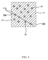
- FIG. 3 is an enlarged view of a portion surrounded by line III of the sliding member shown in FIG.
- FIG. 4 is a cross-sectional view schematically showing a sliding member according to the second embodiment of the present invention.
- FIG. 5 is an enlarged view of a portion surrounded by a V line of the sliding member shown in FIG.
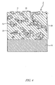
- FIG. 6 is an enlarged view of a portion surrounded by the VI line of the sliding member shown in FIG.
- FIG. 7 is a cross-sectional view schematically showing a sliding member according to the third embodiment of the present invention.
- FIG. 8 is an enlarged view of a portion surrounded by the line VIII of the sliding member shown in FIG.
- FIG. 9 is an enlarged view of a portion surrounded by line IX of the sliding member shown in FIG.
- FIG. 10 is a cross-sectional view schematically showing a sliding member according to the fourth embodiment of the present invention.
- FIG. 11 is a cross-sectional view schematically showing a sliding member of an internal combustion engine having the sliding member at a sliding portion of the internal combustion engine.
- FIG. 12 is a cross-sectional view schematically showing a bearing mechanism of an internal combustion engine having a sliding member on a bearing metal of the bearing mechanism of the internal combustion engine.
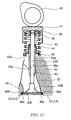
- FIG. 13 is a cross-sectional view schematically showing the wear test apparatus.
- 14 is a cross-sectional transmission electron microscope (TEM) image of the sliding member of Example 3.
- FIG. 15 is a graph showing the results of energy dispersive X-ray (EDX) analysis in the sliding member of Example 3.
- TEM
- FIG. 1 is a cross-sectional view schematically showing a sliding member according to the first embodiment of the present invention.
- FIG. 2 is an enlarged view of a portion surrounded by line II of the sliding member shown in FIG.
- FIG. 3 is an enlarged view of a portion surrounded by line III of the sliding member shown in FIG.
- the sliding member 1 of this embodiment includes a base material 10 and a coating layer 20 formed on the base material 10.
- the coating layer 20 has a copper alloy portion 21 derived from a plurality of precipitation hardening type copper alloy particles.
- the copper alloy parts 21 and 21 are couple
- the copper alloy part contains nickel and silicon as additive elements.
- the content of nickel in the copper alloy part is 2 to 5% by mass.
- the coating layer 20 may have pores 20a.
- At least one of the copper alloy portions 21 has at least one precipitated phase inside the copper alloy portion and at the interface 21 a between the copper alloy portions 21 and 21. 25 is preferable.
- the coating layer 20 may have pores 20a.
- the “precipitation hardening type copper alloy” means not only the copper alloy after precipitation hardening but also includes the copper alloy before precipitation hardening. And in a copper alloy part, although it is preferable that it is a copper alloy after all the copper alloy parts have carried out precipitation hardening, it is not limited to this. For example, in a plurality of copper alloy parts, it may be a copper alloy after some of the copper alloy parts are precipitation hardened, and may be a copper alloy before the remaining copper alloy parts are precipitation hardened. Further, for example, in a plurality of copper alloy parts, a copper alloy before all the copper alloy parts are precipitation hardened may be used.
- the precipitation hardening type copper alloy is sometimes called a particle dispersion strengthened type copper alloy.
- the sliding member of the present embodiment includes a base material and a coating layer formed on the base material, and the coating layer has a copper alloy portion derived from a plurality of precipitation hardening type copper alloy particles.
- the copper alloy part is bonded through an interface, the copper alloy part contains nickel and silicon as additive elements, and the nickel content in the copper alloy part is 2 to 5% by mass. So it has excellent wear resistance.
- At least one of the copper alloy portions includes at least one precipitated phase inside the copper alloy portion and at the interface between the copper alloy portions.
- Such a sliding member has better wear resistance.
- a deposited phase made of nickel silicide (Ni 2 Si) having an excellent effect of improving wear resistance is uniformly contained in the coating layer.
- the nickel content is less than 2% by mass, the amount of the deposited phase film formed of nickel silicide (Ni 2 Si) excellent in the effect of improving wear resistance is not sufficient.
- Ni 2 Si nickel silicide
- the content ratio of nickel and silicon (Ni: Si) is in the range of 3.5 to 4.5: 1 by mass ratio.
- the silicon content is preferably 0.5 to 1.25% by mass. However, it is not limited to such a range, and it goes without saying that it may be outside this range as long as the effects of the present invention can be exhibited.
- precipitation hardening type copper alloy particles (hereinafter sometimes referred to as “copper alloy particles”), which are raw materials used in the manufacturing method of the sliding member, are sprayed onto the base material to obtain copper alloy particles.
- copper alloy particles When the material collides with the base material or the copper alloy part adhering to the base material, a part of the kinetic energy is converted into thermal energy, and between the base material and the copper alloy particle or between the copper alloy particle and the copper alloy part. It is also considered that the deposition and the atomic diffusion progress and the precipitated phase is uniformly formed.
- copper alloy parts are bonded through an interface means that welding, atomic diffusion, and further described below, a sag (entry), plastic deformation part, between copper alloy parts. It means that at least one of the formations has occurred. In the first or second embodiment, indentation (entrance) or plastic deformation portion formation may occur.
- the substrate 10 is not particularly limited, but is preferably a metal that can be applied to a sliding member manufacturing method described later in detail, that is, a coating layer forming method. Needless to say, it is preferable that the base material be usable in a high-temperature environment to which the sliding member is applied when the sliding member is used as a sliding member of an internal combustion engine.
- the aluminum alloy for example, AC2A, AC8A, ADC12, etc. defined in Japanese Industrial Standard are preferably applied.
- an iron alloy it is preferable to apply SUS304, an iron-type sintered alloy, etc. which are prescribed
- a copper alloy it is preferable to apply beryllium copper, a copper alloy system sintered alloy, etc., for example.
- the coating layer 20 is not particularly limited with respect to the porosity.
- the porosity of the coating layer is preferably as small as possible.
- the porosity in the cross section of the coating layer is preferably 3 area% or less, more preferably 1 area% or less, In particular, 0 area% is preferable. At this time, since the porosity can be reduced to 0.1% by area, from the viewpoint that excellent wear resistance and productivity can be improved in a well-balanced manner. It is preferably 1 to 3 area%.
- the porosity in the cross section of the coating layer is obtained by, for example, observing a cross-sectional scanning electron microscope (SEM) image of the cross-section of the coating layer, and image processing such as binarization of the cross-sectional scanning electron microscope (SEM) image. Can be calculated.
- SEM cross-sectional scanning electron microscope
- the thickness of the coating layer 20 is not particularly limited. That is, the thickness of the coating layer may be appropriately adjusted depending on the temperature of the portion to be applied and the sliding environment.
- the thickness is preferably 0.05 to 5.0 mm, and preferably 0.1 to 2.0 mm. Is more preferable. If the thickness is less than 0.05 mm, the rigidity of the coating layer itself is insufficient, and plastic deformation may occur particularly when the substrate strength is low. If it exceeds 10 mm, the coating layer may be peeled off due to the relationship between the residual stress generated during film formation and the interfacial adhesion.
- the precipitation hardening type copper alloy contained in the copper alloy part 21 is not particularly limited as long as it contains nickel and silicon and the nickel content is 2 to 5% by mass. It is preferable to apply what is called a Corson alloy. Thereby, it has the outstanding abrasion resistance.
- the present invention is not limited to this, and for example, a precipitation hardening type copper alloy to which chromium, zirconium, or vanadium is further added alone or in any combination thereof can be applied. Thereby, it is possible to apply various materials according to the specifications required for the sliding member. Needless to say, other elements may be added to the precipitation hardening copper alloy.
- FIG. 4 is a cross-sectional view schematically showing a sliding member according to the second embodiment of the present invention.
- FIG. 5 is an enlarged view of a portion surrounded by the V line of the sliding member shown in FIG.
- FIG. 6 is an enlarged view of a portion surrounded by a VI line of the sliding member shown in FIG.
- the sliding member 2 of the present embodiment has a hard particle portion 23 derived from a plurality of hard particles whose coating layer 20 is harder than the copper alloy portion 21, for example, The copper alloy parts 21 and 21, the copper alloy part 21 and the hard particle part 23, and the hard particle parts 23 and 23 are bonded to each other through the interface with the sliding member of the first embodiment. It is different.
- At least one of the copper alloy portions 21 includes at least one precipitated phase 25 in the inside and the interface 21 a between the copper alloy portions 21 and 21. It is preferable.
- the coating layer 20 may have pores 20a.
- the vicinity of the interface 21 a of the copper alloy portion 21 adjacent to the hard particle portion 23 is, for example, a region from the interface 21a to the inside of the copper alloy portion 21 as indicated by an arrow X in FIG. easy, precipitation phase 25 consisting of nickel silicide (Ni 2 Si) is included in the uniform easily.
- the coating layer 20 may have pores 20a.
- the sliding member of the present embodiment includes a base material and a coating layer formed on the base material, and the coating layer is harder than the predetermined copper alloy portion and the copper alloy portion described above.
- a sliding member having a hard particle part, and these parts (for example, copper alloy parts, copper alloy part and hard particle part, hard particle parts) are bonded via an interface. As such, it has better wear resistance.
- a mixture containing copper alloy particles, which are raw materials used in the manufacturing method of the sliding member, and hard particles harder than the copper alloy particles is sprayed onto the base material, and the hard particles are the base material.
- the base material has an oxide film that inhibits the adhesion between the base material and the coating layer on the surface, the oxide film is removed, and the new interface having excellent adhesion with the coating layer. This is thought to be due to the exposed formation on the substrate.
- the hard particle part 23 is not particularly limited as long as it is harder than the copper alloy part.
- an alloy particle part or a ceramic particle part or a hard particle part obtained by mixing these at an arbitrary ratio is applied. Can do.
- the alloy particle portion can have better wear resistance, iron-based alloy particles, cobalt-based alloy particles, chromium-based alloy particles, nickel-based alloy particles or molybdenum-based alloy particles Alternatively, it is preferable to apply hard particles in which these are mixed at an arbitrary ratio.
- the Vickers hardness that is measured and calculated in this way can be used as an index.
- the Vickers hardness is, for example, about 3 to 30 particles and at least about 3 to 5 particles, about 3 to 30 points for the copper alloy part and hard particle part in the coating layer, and at least 3 to 5 points.
- the calculated average value obtained by measuring the degree is applied.
- observation of a scanning electron microscope (SEM) image, a transmission electron microscope (TEM) image, etc. of the coating layer is performed as necessary. And energy dispersive X-ray (EDX) analysis.
- iron-based alloy examples include SUS440C defined by Japanese Industrial Standard.
- TRIBALOY (trademark) T-400, T-800 etc. examples of the chromium-based alloy include ferrochrome.
- nickel base alloy examples of the TRIBALOY (trademark) T-700 etc.
- molybdenum-based alloy examples include ferromolybdenum.
- ceramics include WC / Co and Al 2 O 3 . Among them, it is preferable to apply a cobalt-based alloy having excellent wear resistance, and specifically, TRIBALOY (registered trademark) T-400, T-800, and the like are preferably applied.
- the ratio of the hard particle portion in the cross section of the coating layer is 1 to 50 areas from the viewpoint of wear resistance, and if necessary, more excellent thermal conductivity. %, Preferably 1 to 25 area%, more preferably 1 to 18 area%, and particularly preferably 5 to 18 area%. However, it is not limited to such a range, and it goes without saying that it may be outside this range as long as the effects of the present invention can be exhibited.
- the ratio of the hard particle part in the cross section of a coating layer is images, such as observation of the scanning electron microscope (SEM) image of the cross section in a coating layer, etc., and binarization of a cross sectional scanning electron microscope (SEM) image, for example It can be calculated by processing. Obviously, the area% calculated by observing the cross section can be read as volume%, and it is needless to say that the volume% can be read as weight% by converting the volume% by the density of each particle.
- the ratio of the hard particle portion in the cross section of the coating layer is preferably 1 to 50 area%, In the case where high thermal conductivity is not necessarily required but excellent wear resistance is required, the ratio of the hard particle portion in the cross section of the coating layer may be 50 to 99 area%. Moreover, other parts other than a copper alloy part and a hard particle part may be included.
- the hard particle part 23 is not particularly limited as long as it is harder than the copper alloy part.
- the contact area with the copper alloy part can be improved, and the wear resistance can be improved. From the viewpoint, it is preferable to have a non-spherical shape.
- the hard particle part has an aspherical shape
- the aspect ratio of the hard particle part is 1.3 or more in median value.
- the aspect ratio of a hard particle part is 1.3 or more and 2.0 or less in a median value.
- the “aspect ratio” is (maximum major axis / maximum major axis) in each hard particle portion when an arbitrary cross section along the layer thickness direction of the coating layer is observed with a scanning electron microscope (SEM) or the like. Width).
- the “maximum major axis” is the distance between any two points on the outline of the hard particle portion when an arbitrary cross section along the layer thickness direction of the coating layer is observed with a scanning electron microscope (SEM) or the like. It means the maximum distance. Further, when calculating the median value of the aspect ratio, for example, about 3 to 30 hard particle portions observed in several to several tens of visual fields may be measured.
- FIG. 7 is a cross-sectional view schematically showing a sliding member according to the third embodiment of the present invention.
- FIG. 8 is an enlarged view of a portion surrounded by line VIII of the sliding member shown in FIG.
- FIG. 9 is an enlarged view of a portion surrounded by the line IX of the sliding member shown in FIG.
- the base material 10 has a plastic deformation portion 10b having a flat concave portion, and the coating layer 20 is deposited with a flat copper alloy portion 21. Having the plastic deformation portion 20b having the above-described structure is different from the sliding member of the first or second embodiment.
- the coating layer is formed with only the copper alloy portion of the copper alloy portion and the hard particle portion, or when one of the base material and the coating layer has a plastic deformation portion. Needless to say, it is included in the range.
- the sliding member of the present embodiment includes a base material and a coating layer formed on the base material, and the coating layer has the predetermined copper alloy portion described above, and if necessary, a copper alloy portion.
- the hard particle portion which is harder than the above, and these portions (for example, copper alloy portions, copper alloy portion and hard particle portion, hard particle portions) are bonded via an interface, Since at least one of the base material and the coating layer is a sliding member having a plastically deformed portion, it has further excellent wear resistance.
- a mixture containing copper alloy particles, which are raw materials used in the manufacturing method of the sliding member, and hard particles that are harder than the copper alloy particles is sprayed onto the substrate, and the hard particles collide with the substrate. Then, for example, when the base material has an oxide film on the surface that inhibits the adhesion between the base material and the coating layer, the oxide film is removed and a new interface having excellent adhesion with the coating layer is formed. This is thought to be because the material is exposed.
- the adhesion between the base material and the coating layer is improved by the anchor effect caused by the copper alloy particles sinking into the base material.
- the adhesiveness between the base material and the coating layer is improved by forming the plastic deformation portion including the flat concave portion on the base material.
- the copper alloy particles collide with the base material or the copper alloy part attached to the base material the copper alloy particles or the copper alloy part becomes flat, and thereby the adhesiveness between the copper alloy parts in the coating layer This is also considered to be improved. That is, as described above, by forming a plastic deformation portion having a structure in which a flat copper alloy portion is deposited on the coating layer, there are few gaps (pores) between the copper alloy portion and the copper alloy portion. It is also considered that the adhesion between the copper alloy parts in the coating layer is improved.
- the coating layer 20 may have pores 20a.
- the pores of the coating layer 20 are reduced and it is difficult to observe.
- a process of forming a flat recess in the base material, or the copper alloy particles or the copper alloy part becomes flat.
- the heat generated by the plastic deformation causes the heat treatment between the base material and the copper alloy particles or between the copper alloy particles and the copper alloy portion. It is also considered that welding and atomic diffusion proceed.
- the adhesion between the base material and the coating layer is caused by the anchor effect that the hard particles sink into the base material or the copper alloy part. This is also considered to be improved.
- the adhesiveness between the base material and the coating layer is improved by forming the plastic deformation portion including the flat concave portion on the base material.
- the hard particle portions where the hard particles are attached to the base material or the copper alloy particles are attached to the base material it is also considered that the anchor effect by the penetration improves the adhesion between the copper alloy part and the hard particle part in the coating layer.
- a hard particle part has the non-spherical shape mentioned above, a hard particle tends to sink into the copper alloy part which adhered to the base material, and a copper alloy particle tends to sink into the hard particle part which adhered to the base material.
- FIG. 10 is a cross-sectional view schematically showing a sliding member according to the fourth embodiment of the present invention.
- the sliding member 4 of the present embodiment includes the predetermined intermediate layer 30 formed over the entire area between the base material 10 and the coating layer 20.
- the predetermined intermediate layer 30 includes a diffusion layer, an intermetallic compound layer, or a diffusion layer and an intermetallic compound layer.
- the case where the intermediate layer includes a diffusion layer includes the case where the intermediate layer is a diffusion layer.
- the case where the intermediate layer includes an intermetallic compound layer includes the case where the intermediate layer is an intermetallic compound layer.
- the coating layer is formed having only a copper alloy portion among the copper alloy portion and the hard particle portion, or when both the base material and the coating layer have a plastic deformation portion, the base material and It goes without saying that the case where one of the coating layers has a plastically deformed portion is included in the scope of the present invention.
- the sliding member of the present embodiment includes a base material and a coating layer formed on the base material, and the coating layer has the predetermined copper alloy portion described above, and if necessary, a copper alloy portion.
- the hard particle portion which is harder than the above, and these portions (for example, copper alloy portions, copper alloy portion and hard particle portion, hard particle portions) are bonded via an interface, Since the sliding member includes an intermediate layer including at least one of a diffusion layer and an intermetallic compound layer formed in at least a part between the base material and the coating layer, it has further excellent wear resistance. Needless to say, at least one of the substrate and the coating layer may have a plastic deformation portion.
- copper alloy particles which are raw materials used in the manufacturing method of the sliding member, are sprayed onto the base material. For example, when the copper alloy particles collide with the base material, part of the kinetic energy is converted into thermal energy. And diffusion of component elements contained between the base material and the copper alloy particles and at least one of the copper alloy parts attached to the base material occurs between the base material and the coating layer. This is probably because an intermediate layer including at least one of the compound layers is formed.
- the base material has an oxide film that inhibits adhesion between the base material and the coating layer on the surface, It is also considered that the oxide film was removed, the newly formed interface was exposed and formed on the substrate, and the diffusion of the component elements was promoted.
- the intermediate layer 30 includes a diffusion layer, an intermetallic compound layer, or a diffusion layer and an intermetallic compound layer.
- a diffusion layer what has a gradient structure about a composition can be mentioned as a suitable example.
- the diffusion layer is not limited to one having a gradient structure with respect to the composition.
- an intermediate layer including an intermetallic compound layer a layer having a structure in which an intermetallic compound layer is sandwiched between diffusion layers having a gradient structure with respect to the composition may be cited as a preferable example. it can.
- the intermediate layer includes, for example, component elements included in the base material and component elements included in the copper alloy portion.
- an intermediate layer made of an alloy containing aluminum and copper is formed.
- the present invention is not limited to this.
- an intermediate layer made of an alloy containing stainless steel (SUS) component elements and copper is formed. .
- FIG. 11 is a cross-sectional view schematically showing a sliding member of an internal combustion engine having the sliding member at a sliding portion of the internal combustion engine. More specifically, it is a cross-sectional view schematically showing a valve mechanism including an engine valve.
- a valve mechanism including an engine valve.
- FIG. 11 when the cam lobe 40 rotates, the valve lifter 41 is pushed down while compressing the valve spring 42, and at the same time, the engine valve 43 is guided and pushed down by a valve guide 45 having a stem seal 44.
- the engine valve 43 is separated from the seating portion 46A of the engine valve 43 at this time, and the exhaust port 47 and a combustion chamber (not shown) communicate with each other (engine valve is open).
- valve face 43B of the engine valve 43 corresponding to the opening / closing valve portion of the combustion chamber (not shown) is in contact or non-contact with the seating portion 46A of the engine valve 43 in the cylinder head 46 during operation.
- FIG. 11 shows the exhaust port 47 side, the sliding member of the present invention can be applied to an intake port side (not shown).
- the sliding member (1, 2, 3, 4) in the fourth embodiment is applied. Thereby, it has the outstanding abrasion resistance.
- the sliding member of the present invention to the cylinder head, it is possible to eliminate the press-fitting type valve seat. As a result, the exhaust ports and intake ports can be freely shaped and the diameter of the engine valve can be increased, and the fuel consumption, output, torque, etc. of the engine can be improved.
- a sliding member can also be applied. Thereby, it has the outstanding abrasion resistance.
- the cylinder head of the present embodiment has the sliding member of the above-described embodiment in the seat portion of the engine valve.
- another cylinder head of the present embodiment is a cylinder head including the valve seat having the sliding member of the above-described embodiment, and the sliding member may be provided on a seating portion of the engine valve of the valve seat.
- the valve seat of this embodiment has the sliding member of the said embodiment in the seating part of an engine valve.
- the engine valve of the present embodiment preferably has the sliding member of the above embodiment on the valve face.
- the other engine valve of this embodiment has the sliding member of the said embodiment in a sliding site
- FIG. 12 is a cross-sectional view schematically showing a bearing mechanism of an internal combustion engine having a sliding member on a bearing metal of the bearing mechanism of the internal combustion engine. More specifically, it is a cross-sectional view schematically showing a bearing metal that is a sliding member of a connecting rod.
- a large end 60A on the crank side (not shown) of the connecting rod 60 is divided into two vertically.
- a bearing metal 62 divided into two parts for receiving the crankpin 61 is disposed at the large end 60A.
- a sliding member having the above-described coating layer formed on the sliding surface 62a for example, the sliding member (1, 2, 4 in the first to fourth embodiments described above). 3, 4) is applied. Thereby, it has the outstanding abrasion resistance.
- a sliding member in which the above-described coating layer is formed on the sliding surface of the bearing metal divided into two to receive the piston pin at the small end of the connecting rod on the piston side (not shown)
- the sliding members in the first to fourth embodiments described above can also be applied. Thereby, it has the outstanding abrasion resistance.
- the bearing mechanism of the internal combustion engine of the present embodiment preferably has the sliding member of the above embodiment on the bearing metal of the bearing mechanism of the internal combustion engine. It is also possible to form a film directly on the sliding surface on the large end side of the connecting rod (direct formation without using metal). It is also possible to form a film directly on the sliding surface on the small end side of the connecting rod (direct formation without using metal).
- the sliding member of the internal combustion engine of this embodiment can also be applied to a piston ring or a piston. That is, it is preferable to apply the coating layer to the surface of the piston ring. Further, it is preferable to apply the coating layer to the inner surface of the ring groove of the piston. Furthermore, in the sliding member of the internal combustion engine of the present embodiment, it is preferable that the coating layer is applied to the inner surface of the cylinder bore (can be used as an alternative to a cylinder liner or an alternative to bore spraying). Further, in the sliding member of the internal combustion engine of the present embodiment, it is preferable to apply the coating layer to the metal of the journal of the crankshaft.
- the coating layer is directly formed on the metal portion of the crankshaft journal (the coating layer is formed directly without using metal). In the sliding member of the internal combustion engine of the present embodiment, it is preferable to apply the coating layer to the metal surface of the camshaft journal. Further, in the sliding member of the internal combustion engine of the present embodiment, it is preferable that the coating layer is directly formed on the metal portion of the camshaft journal (the coating layer is formed directly without using metal). In the sliding member of the internal combustion engine of the present embodiment, it is preferable to apply the coating layer to the cam lobe surface of the camshaft.
- the sliding member of the internal combustion engine of the present embodiment applies the coating layer to the piston and piston pin metal. Moreover, it is preferable that the sliding member of the internal combustion engine of this embodiment forms a film layer directly in the metal part of a piston and a piston pin. Furthermore, it is preferable that the sliding member of the internal combustion engine of the present embodiment applies the coating layer to the surface of the piston skirt. In the sliding member of the internal combustion engine of the present embodiment, it is preferable to apply the coating layer to the crown surface of the valve lifter. Furthermore, in the sliding member of the internal combustion engine of the present embodiment, it is preferable to apply the coating layer to the side surface of the valve lifter.
- the coating layer is applied to a sliding surface of the cylinder head with the lifter valve lifter. Further, in the sliding member of the internal combustion engine of the present embodiment, the coating layer is formed on the surface of the sprocket teeth (for example, on the aluminum sintered alloy sprocket instead of the iron sintered alloy sprocket). It is preferable to apply to. In the sliding member of the internal combustion engine of the present embodiment, it is preferable to apply the coating layer to the pin of the chain. Furthermore, the sliding member of the internal combustion engine of the present embodiment preferably applies the coating layer to the chain plate.
- the coating layer is formed on the surface of the tooth of a gear other than the internal combustion engine (in this case, for example, a steel gear is formed into an aluminum alloy, and the coating is formed on the aluminum alloy.
- a gear other than the internal combustion engine examples include an automobile differential gear, an automobile generator, and an automobile generator.
- the sliding member in the first to fourth embodiments described above is preferably applied to all sliding bearings (slide bearings in a broad sense that is not a rolling bearing).
- the manufacturing method of the sliding member includes, for example, the base material in the first to fourth embodiments described above and the coating layer formed on the base material, and the coating layer is the predetermined copper alloy described above.
- Part, or the above-mentioned predetermined copper alloy part and hard particle part, and these parts are interposed via the interface. Is a method of manufacturing a sliding member bonded together.
- the predetermined copper alloy particles described above or a mixture containing the predetermined copper alloy particles and hard particles described above is sprayed on the base material in a non-molten state, It has a copper alloy part, or the predetermined copper alloy part and hard particle part mentioned above, and these parts (for example, copper alloy parts, a copper alloy part, a hard particle part, and hard particle parts) are interfaces. Forming a coating layer bonded via the substrate on the substrate.
- the above-described predetermined copper alloy particles that are prevented from precipitating additional elements as a non-molten state, or a mixture containing the above-described predetermined copper alloy particles and hard particles are sprayed onto the base material, and the above-mentioned
- the predetermined copper alloy part or the predetermined copper alloy part and the hard particle part described above are included (for example, the copper alloy parts, the copper alloy part, the hard particle part, and the hard particle part).
- the coating layer having excellent wear resistance can be efficiently formed by forming the coating layer by a method called kinetic spray, cold spray, warm spray or the like.
- the sliding member of the present invention is not limited to those manufactured by such a manufacturing method.
- the copper alloy particles or the mixture when the copper alloy particles or the mixture is sprayed on the base material, the copper alloy particles or the mixture is sprayed on the base material, and the copper alloy particles are sprayed on the base material. It is preferable to spray at a speed that forms a plastically deformed portion on at least one side. Thereby, the coating layer which was more excellent in abrasion resistance can be formed efficiently.
- the speed at which the copper alloy particles are sprayed is not limited to the above.
- the particle speed is preferably 300 to 1200 m / s, more preferably 500 to 1000 m / s, and still more preferably 600 to 800 m / s.
- the pressure of the working gas supplied for spraying the particles is preferably 2 to 5 MPa, and more preferably 3.5 to 5 MPa. If the pressure of the working gas is less than 2 MPa, the particle velocity may not be obtained and the porosity may increase. However, it is not limited to such a range, and it goes without saying that it may be outside this range as long as the effects of the present invention can be exhibited.
- the temperature of the working gas is not particularly limited, but is preferably 400 to 800 ° C., and more preferably 600 to 800 ° C., for example.
- the temperature of the working gas is less than 400 ° C., the porosity may increase and the wear resistance may decrease. Further, if the temperature of the working gas exceeds 800 ° C., nozzle clogging may occur.
- it is not limited to such a range, and it goes without saying that it may be outside this range as long as the effects of the present invention can be exhibited.
- the type of working gas is not particularly limited, and examples thereof include nitrogen and helium. These may be used individually by 1 type and may be used in combination of multiple types. Further, a mixture of fuel gas and nitrogen may be used.
- aging treatment or tempering may be performed at 250 to 500 ° C. for 0.5 to 4 hours. Thereby, abrasion resistance can be improved. Further, this aging treatment or tempering can be performed, for example, by using heat received from the combustion chamber during a test operation in an inspection after the assembly of the engine.
- the copper alloy particles used as the raw material are not particularly limited, but are preferably in a non-molten state and composed of the predetermined copper alloy particles described above. Needless to say, a copper alloy before precipitation hardening is preferable.
- the copper alloy particles are preferably in the state of, for example, a supersaturated solid solution. By being in the state of supersaturated solid solution, since it has a large ductility, in other words, it has deformability, the coating layer can be formed efficiently and the film formability can be improved.
- the particles in a supersaturated solid solution state are not particularly limited. For example, it is preferable to apply rapidly solidified particles obtained by rapid solidification by an atomizing method or the like.
- the copper alloy particles used as the raw material are not particularly limited, but the compressive strength of the particles is preferably 50 to 110 N / mm 2 .
- the compressive strength of the particles is preferably 50 to 110 N / mm 2 .
- compressive strength of particles is defined as compressive strength when a particle is changed by 10% in the load direction when a load is applied to the particles with a flat indenter or the like.
- the measurement method conforms to JIS R 1639-5 "Fine ceramics-(condylar) grain property measurement method-Part 5: Single grain crushing strength", and the test load is 500 mN.
- the hard particles used as the raw material are not particularly limited, but are preferably in a non-molten state, preferably harder than the copper alloy particles, and have a non-spherical shape. It is preferable. For example, it is preferable to apply alloy particles or ceramic particles or a mixture containing these in any proportion. As the alloy particles, it is preferable to apply iron-based alloy particles, cobalt-based alloy particles, chromium-based alloy particles, nickel-based alloy particles, molybdenum-based alloy particles, or a mixture containing these in an arbitrary ratio.
- the hard particles used as the raw material are not particularly limited, but it is preferable to apply particles produced by a water atomization method.
- particles When particles are produced by the water atomization method, water hits the electric droplets and the droplets are deformed. At that time, the particles are cooled by water and become non-spherical shapes as distorted particles.
- cooling is insufficient and the particle shape returns to a spherical shape.
- the particle size of the copper alloy particles and hard particles used as the raw material is not particularly limited, but is preferably 150 ⁇ m or less, and more preferably 75 ⁇ m or less.
- the particle size of the particles can be adjusted by a sieve or a conventionally known appropriate method.
- the “particle size” the number-based d95 measured and calculated using an image analysis type particle size distribution measuring apparatus can be used.
- the “particle diameter” when measuring and calculating such a particle size for example, the maximum distance between any two points on the contour line of the observed particle (observation surface) may be adopted. it can.
- the present invention is not limited to this, and for example, the equivalent circle diameter of the observed particles (observation surface) can be adopted.
- d95 based on the number measured and calculated using a laser diffraction / scattering particle size distribution measuring apparatus may be used.
- a coating layer is formed using such copper alloy particles and hard particles, a coating layer with more excellent wear resistance can be efficiently formed.
- the average particle diameter of the copper alloy particles and hard particles used as the raw material is not particularly limited, but is preferably 5 to 40 ⁇ m, and more preferably 20 to 40 ⁇ m. If the average particle size is less than 5 ⁇ m, the supply of particles may be poor due to low fluidity. On the other hand, if the average particle diameter exceeds 50 ⁇ m, the film formation may be poor due to insufficient particle speed during film formation.
- the “average particle size” for example, a number-based average particle size (d50) measured and calculated using an image analysis type particle size distribution measuring apparatus can be used.
- particle diameter when measuring and calculating such an average particle diameter, for example, the maximum distance between any two points on the contour of the observed particle (observation surface) is adopted.
- the present invention is not limited to this, and for example, the equivalent circle diameter of the observed particle (observation surface) can be adopted. Furthermore, a number-based average particle diameter (d50) measured and calculated using a laser diffraction / scattering particle diameter distribution measuring apparatus may be used. However, it is not limited to such a range, and it goes without saying that it may be outside this range as long as the effects of the present invention can be exhibited.
- the average particle diameter of the copper alloy particles is preferably smaller than the average particle diameter of the hard particles.
- the sliding member is formed using such copper alloy particles and hard particles, a coating layer having more excellent wear resistance can be efficiently formed.
- the aspect ratio of the median value of the copper alloy particles and hard particles used as the raw material is not particularly limited.
- an aspect ratio measured and calculated using an image analysis type particle size distribution measuring apparatus can be used.
- the aspect ratio can be measured and calculated using a scale by enlarging a scanning electron microscope (SEM) image of each particle.
- Example 1 copper-nickel-silicon alloy particles (composition: Cu-3Ni-0.7Si, water atomized particles, particle size (d95): 60.7 ⁇ m, average particle size (d50)): 27. 7 ⁇ m, aspect ratio (median value): 1.59, compression strength 67.1 N / mm 2 , Vickers hardness: 64.1 HV0.01) were prepared.
- the particle size (d95) is based on the number, and was measured and calculated using an image analysis type particle size distribution measuring apparatus.
- the average particle size (d50) is based on the number and was measured and calculated using an image analysis type particle size distribution measuring apparatus.
- the “particle diameter” the maximum distance between any two points on the contour line of the observed particle (observation surface) was adopted.
- the aspect ratio (median value) was measured and calculated using a scale by enlarging a scanning electron microscope (SEM) image.
- the compressive strength measured the compressive strength when the particle diameter in the load-load direction changed 10% by adding a load with respect to particle
- MCT-510 ultra fine compression tester
- the number of measurements was made into ten pieces.
- the Vickers hardness was measured and calculated in accordance with a Vickers hardness test (JIS Z 2244) defined by Japanese Industrial Standards.
- the number of measurements was made into ten pieces.
- the aluminum base material Japanese Industrial Standard H 4040 A5056
- H 4040 A5056 Japanese Industrial Standard H 4040 A5056
- the prepared aluminum alloy is mounted on the rotary table, and while rotating the rotary table, the prepared copper alloy particles are placed on the prepared aluminum substrate on a high-pressure cold spray device (Plasma Giken Kogyo Co., Ltd., PCS).
- a high-pressure cold spray device (Plasma Giken Kogyo Co., Ltd., PCS).
- working gas type; nitrogen, temperature; 600 ° C., particle velocity: 700 to 750 m / s, pressure; 4 MPa), sprayed with a coating layer having a coating layer thickness of 0.4 to 0.5 mm as a base material Formed on top.
- the thickness of the coating layer is 0.2 mm (the same applies hereinafter).
- Example 2 to Example 4 As shown in Table 1, the same operation as in Example 1 was repeated except that the specifications and blending ratios of the copper alloy particles and the hard particles were changed to obtain sliding members of respective examples.
- Co—Mo—Cr means a cobalt-based alloy.
- the Vickers hardness of the copper alloy part and the hard particle part in the coating layer of each example conforms to the Vickers hardness test (JIS Z 2244) defined in Japanese Industrial Standards. Measured and calculated. In addition, in order to obtain
- the precipitation phase in the copper alloy part of each example was specified by observation of a transmission electron microscope (TEM) image of a cross section in the coating layer and energy dispersive X-ray (EDX) analysis.
- TEM transmission electron microscope
- EDX energy dispersive X-ray
- the presence or absence of an intermediate layer or the presence or absence of a plastic deformation portion in the cross section of the sliding member in each example is determined by observing the cross section of the coating layer with a scanning electron microscope (SEM) image and energy dispersive X-ray (EDX) analysis. Specified by. In all of Examples 1 to 4, precipitated phases were observed, and plastic deformation portions were observed in the base material and the coating layer.
- FIG. 13 is a sectional view schematically showing the wear test apparatus. As shown in FIG. 13, using actual engine parts such as a valve spring 42, an engine valve 43, a stem seal 44, a valve guide 45, a cylinder head 46, 46 ', and a cotter 49, it resembles an engine valve mechanism. A wear test device was constructed. The sliding member (1, 2, 3, 4) obtained in each of the above examples was applied as the seating portion 46A of the engine valve 43 in the cylinder head 46. The sliding member (1, 2, 3, 4) includes a predetermined coating layer 20 formed on the substrate 10.
- the engine valve 43 in the drawing shows an open state, and the engine valve 43 is vibrated in the vertical direction indicated by the arrow Y in the drawing by an eccentric cam (not shown), and the opening and closing of the engine valve 43 is repeated.
- the sliding surface 46a of the seating portion 46A of the engine valve 43 in the cylinder head 46 is brought into a high temperature environment by the flame F of the gas burner B.
- the temperature of the seating portion 46A is measured by a thermometer T.
- cooling water W circulates in the cylinder head 46.
- the amount of wear was measured and calculated using the wear test apparatus described above under the following test conditions. Specifically, the shape of the engine valve seating in the cylinder head before and after the test is acquired using a shape measuring device, the amount of wear at four locations is measured, the average value is calculated, and this is worn. The amount. The obtained results are also shown in Tables 1 and 2.
- Examples 1 to 4 belonging to the scope of the present invention have less wear compared to Comparative Examples 1 to 3 outside the present invention, and excellent wear resistance even at high temperatures. It turns out that it has sex. In addition, Examples 1 to 4 are excellent in thermal conductivity because they employ copper alloy particles.
- the sliding member having excellent wear resistance as in Examples 1 to 4 was obtained because it had the above-mentioned predetermined copper alloy part, preferably the above-mentioned predetermined copper alloy part and hard particle part. It is considered that a coating layer in which these parts (for example, copper alloy parts, copper alloy parts and hard particle parts, and hard particle parts) are bonded via an interface is formed on the substrate. It is done.
- the sliding member having excellent wear resistance as in Examples 1 to 4 was obtained because at least one of the copper alloy portions had at least nickel silicide inside and / or at the interface. This is also considered to include one precipitated phase.
- the reason why the sliding member having excellent wear resistance as in Examples 1 to 4 was obtained is considered that at least one of the base material and the coating layer has a plastic deformation portion.
- the sliding member having excellent wear resistance as in Examples 1 to 4 was obtained because the porosity in the cross section of the coating layer was 1 area% or less.
- FIG. 14 is a cross-sectional transmission electron microscope (TEM) image in the vicinity of the boundary surface between the base material 10 and the coating layer 20 of the sliding member of Example 3.
- FIG. 15 is a graph showing the results of energy dispersive X-ray (EDX) analysis (line analysis) in the line segment Z shown in FIG. 14 of the sliding member of Example 3. Note that the position P shown in FIG. 14 and the position P shown in FIG. 15 are the same position. Further, in FIG. 15, the position of the end portion on the base material 20 side of the line segment Z shown in FIG. 14 is set to a position of 0.0 ⁇ m, and the position of the end portion of the line segment Z on the coating layer 20 side is set to a position of 2.0 ⁇ m. .
- the sliding member having excellent wear resistance as in Example 3 was obtained because the diffusion layer and the intermetallic compound layer formed at least partially between the base material and the coating layer. It is also considered that an intermediate layer including both of these was provided. Furthermore, the sliding member having excellent wear resistance as in Example 3 was obtained because the intermediate member including the diffusion layer having a gradient structure with respect to the composition was provided, or the intermetallic compound layer was inclined with respect to the composition. It is also considered to include an intermediate layer having a structure sandwiched between diffusion layers having a structure.
- the sliding member having excellent wear resistance as in Examples 1 to 4 was obtained because the hard particle portion was derived from hard particles such as cobalt-based alloy particles. .
- the sliding member having excellent wear resistance as in Examples 1 to 4 was obtained in the above-described method for manufacturing a sliding member, which was in an unmelted state, and was described above.
- the sliding member having excellent wear resistance as in Examples 1 to 4 was obtained when the predetermined copper alloy particles and mixture described above were sprayed onto the substrate. It is also considered that the mixture was sprayed on the base material at a speed at which the copper alloy particles were sprayed on the base material to form a plastic deformation portion on at least one of the base material and the coating layer.
- the sliding members having excellent wear resistance as in Examples 1 to 4 were obtained because the copper alloy particles were in a supersaturated solid solution state or rapidly solidified particles. It is thought that the particles were produced by the water atomization method.
- the sliding member having excellent wear resistance as in Examples 1 to 4 was obtained because the compressive strength of the copper alloy particles was 50 to 110 N / mm 2 .
- the sliding member having excellent wear resistance as in Examples 1 to 4 was obtained because the particle size of the copper alloy particles and the hard particles was 75 ⁇ m or less.
- the sliding member having excellent wear resistance as in Example 3 was obtained because the average particle diameter of the copper alloy particles was smaller than the average particle diameter of the hard particles.
- constituent elements described in each of the above-described embodiments and examples are not limited to each embodiment or each example.
- constituent elements such as specifications and blending ratios of copper alloy particles and hard particles
- the film forming conditions can be changed, and the constituent elements of the embodiments and examples can be combined with those other than the embodiments and examples described above.
Landscapes
- Engineering & Computer Science (AREA)
- Chemical & Material Sciences (AREA)
- Mechanical Engineering (AREA)
- Materials Engineering (AREA)
- General Engineering & Computer Science (AREA)
- Metallurgy (AREA)
- Organic Chemistry (AREA)
- Chemical Kinetics & Catalysis (AREA)
- Manufacturing & Machinery (AREA)
- Composite Materials (AREA)
- Combustion & Propulsion (AREA)
- Physics & Mathematics (AREA)
- Plasma & Fusion (AREA)
- Sliding-Contact Bearings (AREA)
- Other Surface Treatments For Metallic Materials (AREA)
- Powder Metallurgy (AREA)
- Laminated Bodies (AREA)
- Pistons, Piston Rings, And Cylinders (AREA)
Abstract
摺動部材は、基材と、基材上に形成された被膜層とを備える。被膜層は、複数の析出硬 化型銅合金粒子に由来の銅合金部を有し、銅合金部同士が界面を介して結合している。銅 合金部は、添加元素として、ニッケル及びケイ素を含む。銅合金部におけるニッケルの含 有量は、2~5質量%である。 内燃機関の摺動部材は、摺動部材を内燃機関の摺動部位に有する。
Description
本発明は、摺動部材及び内燃機関の摺動部材に関する。
従来、特許文献1は、冷間で加工誘起変態を生じさせることにより基材の表面に硬質皮膜を形成することを可能とした硬質皮膜の形成方法を開示している。そして、この硬質皮膜の形成方法は、基材の表面に固相状態の金属粉末を圧縮性の気体を媒体として吹き付けて硬質の金属皮膜を形成する硬質皮膜の形成方法である。この形成方法において、該金属粉末は加工誘起変態が生じる金属材料で構成されており、該金属粉末を該加工誘起変態が生じる高速で該基材に叩きつけることにより、該金属粉末を扁平に塑性変形させながら該基材の表面に幾重にも堆積させ且つ堆積した該金属粉末に該加工誘起変態を生じさせる。これにより、この形成方法は、該基材に叩きつける前の該金属粉末より高い硬さの金属皮膜を該基材の表面に形成することを特徴とする。
しかしながら、特許文献1に記載された硬質皮膜は、耐摩耗性が不十分であるという問題点があった。
本発明は、このような従来技術の有する課題に鑑みてなされたものである。そして、本発明は、優れた耐摩耗性を有する摺動部材及び内燃機関の摺動部材を提供することを目的とする。
本発明者らは、上記目的を達成するため鋭意検討を重ねた。その結果、析出硬化型銅合金粒子に由来の所定の銅合金部を有し、銅合金部同士が界面を介して結合している被膜層を基材上に形成することにより、上記目的が達成できることを見出し、本発明を完成するに至った。
本発明によれば、優れた耐摩耗性を有する摺動部材及び内燃機関の摺動部材を提供することができる。
以下、本発明の一実施形態に係る摺動部材及び内燃機関の摺動部材について詳細に説明する。
(第1の実施形態)
まず、本発明の第1の実施形態に係る摺動部材について図面を参照しながら詳細に説明する。なお、以下の各実施形態で引用する図面の寸法比率は、説明の都合上誇張されており、実際の比率とは異なる場合がある。
まず、本発明の第1の実施形態に係る摺動部材について図面を参照しながら詳細に説明する。なお、以下の各実施形態で引用する図面の寸法比率は、説明の都合上誇張されており、実際の比率とは異なる場合がある。
図1は、本発明の第1の実施形態に係る摺動部材を模式的に示す断面図である。また、図2は、図1に示した摺動部材のII線で囲んだ部分の拡大図である。さらに、図3は、図1に示した摺動部材のIII線で囲んだ部分の拡大図である。図1及び図2に示すように、本実施形態の摺動部材1は、基材10と、基材10上に形成された被膜層20とを備える。そして、この被膜層20は、複数の析出硬化型銅合金粒子に由来の銅合金部21を有する。また、この被膜層20においては、銅合金部21,21同士が界面21aを介して結合している。さらに、図示しないが、銅合金部は、添加元素として、ニッケル及びケイ素を含む。また、銅合金部におけるニッケルの含有量は、2~5質量%である。なお、被膜層20は、気孔20aを有することがある。
また、図3に示すように、本実施形態の摺動部材1は、銅合金部21の少なくとも1つが、銅合金部の内部及び銅合金部21,21同士の界面21aに少なくとも1つの析出相25を含むことが好ましい。なお、被膜層20は、気孔20aを有することがある。
ここで、本発明において、「析出硬化型銅合金」とは、析出硬化した後の銅合金のみを意味するのではなく、析出硬化する前の銅合金を含むことを意味する。そして、銅合金部において、全ての銅合金部が析出硬化した後の銅合金であることが好ましいが、これに限定されるものではない。例えば、複数の銅合金部において、一部の銅合金部が析出硬化した後の銅合金であり、残部の銅合金部が析出硬化する前の銅合金であってもよい。また、例えば、複数の銅合金部において、全ての銅合金部が析出硬化する前の銅合金であってもよい。なお、析出硬化型銅合金は、粒子分散強化型銅合金と呼ばれることもある。
上述のように、本実施形態の摺動部材は、基材と、基材上に形成された被膜層とを備え、被膜層が複数の析出硬化型銅合金粒子に由来の銅合金部を有し、銅合金部同士が界面を介して結合しており、銅合金部が添加元素としてニッケル及びケイ素を含み、銅合金部におけるニッケルの含有量が2~5質量%である摺動部材であるので、優れた耐摩耗性を有する。
また、上述のように、本実施形態の摺動部材は、銅合金部の少なくとも1つが、銅合金部の内部及び銅合金部同士の界面に少なくとも1つの析出相を含むことが好ましい。このような摺動部材は、より優れた耐摩耗性を有する。
現時点においては、以下のような理由の少なくとも1つにより、上述の効果が得られていると考えている。
ニッケル及びケイ素を含む銅合金部においては、ニッケルの含有量が2~5質量%であると、ニッケル、ケイ素などの化合物が析出することにより、銅合金部が変形し難くなって耐摩耗性が向上すると考えられる。また、耐摩耗性の向上効果に優れたケイ化ニッケル(Ni2Si)からなる析出相が被膜層において均一に含まれることとなるためとも考えられる。ニッケルの含有量が2質量%未満の場合には、耐摩耗性の向上効果に優れたケイ化ニッケル(Ni2Si)からなる析出相の被膜層における形成量が十分なものとならない。また、ニッケルの含有量が5質量%超の場合には、耐摩耗性の向上効果に優れたケイ化ニッケル(Ni2Si)からなる析出相が被膜層において均一に形成されない。なお、特に限定されるものではないが、ニッケルとケイ素の含有量の比(Ni:Si)が質量比で3.5~4.5:1の範囲内にあることが好ましい。また、ケイ素の含有量が0.5~1.25質量%であることが好ましい。但し、このような範囲に何ら制限されるものではなく、本発明の効果を発現できるものであれば、この範囲を外れていてもよいことは言うまでもない。
また、例えば、詳しくは後述するが、摺動部材の製造方法で用いる原料である析出硬化型銅合金粒子(以下「銅合金粒子」ということがある。)を基材上に吹き付け、銅合金粒子が基材や基材に付着した銅合金部に衝突すると、その運動エネルギーの一部が熱エネルギーに変換され、基材と銅合金粒子との間や銅合金粒子と銅合金部との間における溶着や原子拡散が進行し、析出相が均一に形成されるためとも考えられる。
但し、上記の理由以外の理由により上述のような効果が得られていたとしても、本発明の範囲に含まれることは言うまでもない。
なお、本発明において、「銅合金部同士が界面を介して結合している」とは、銅合金部間において、溶着、原子拡散、さらには詳しくは後述する、めり込み(進入)、塑性変形部形成のうちの少なくとも1つが生じていることを意味する。なお、第1又は第2の実施形態において、めり込み(進入)や塑性変形部形成が生じていてもよい。
ここで、各構成要素についてさらに詳細に説明する。
上記基材10としては、特に限定されるものではないが、詳しくは後述する摺動部材の製造方法、つまり、被膜層の形成方法に適用し得る金属が好ましい。また、基材は、摺動部材が内燃機関の摺動部材として用いられた場合において、摺動部材が適用される高温環境下で使用可能であるものであることが好ましいことは言うまでもない。
そして、金属としては、例えば、従来公知のアルミニウムや鉄、チタン、銅などの合金を適用することが好ましい。
また、アルミニウム合金としては、例えば、日本工業規格で規定されているAC2A、AC8A、ADC12などを適用することが好ましい。さらに、鉄合金としては、例えば、日本工業規格で規定されているSUS304、鉄系焼結合金などを適用することが好ましい。また、銅合金としては、例えば、ベリリウム銅や銅合金系焼結合金などを適用することが好ましい。
また、上記被膜層20としては、その気孔率に関して、特に限定されるものではないが、例えば、被膜層の気孔率が大きいと強度が不足し、耐摩耗性を低下させる可能性があるという観点からは、被膜層の気孔率は可能な限り小さいことが好ましい。そして、高い熱伝導性を有する摺動部材とすることができるという観点からは、被膜層の断面における気孔率は3面積%以下であることが好ましく、1面積%以下であることがより好ましく、特に0面積%であることが好ましい。なお、現時点においては、気孔率を0.1面積%まで低減することが可能となっているため、優れた耐摩耗性や生産性の向上などをバランス良く実現し得るという観点からは、0.1~3面積%とすることが好ましい。但し、このような範囲に何ら制限されるものではなく、本発明の効果を発現できるものであれば、この範囲を外れていてもよいことは言うまでもない。また、被膜層の断面における気孔率は、例えば、被膜層における断面の走査型電子顕微鏡(SEM)像などの観察、及び断面走査型電子顕微鏡(SEM)像の2値化などの画像処理によって、算出することができる。
さらに、上記被膜層20としては、その厚みに関して、特に限定されるものではない。つまり、被膜層の厚みは適用される部位の温度や摺動環境により適宜調整すればよいが、例えば、0.05~5.0mmとすることが好ましく、0.1~2.0mmとすることがより好ましい。0.05mm未満であると、被膜層自体の剛性が不足するため、特に基材強度が低い場合に塑性変形を起こすことがある。また、10mm超であると、成膜時に発生する残留応力と界面密着力の関係により被膜層の剥離が生じる可能性がある。
上記銅合金部21に含まれる析出硬化型銅合金としては、ニッケル及びケイ素を含み、ニッケルの含有量が2~5質量%であれば、特に限定されるものではない。いわゆるコルソン合金と呼ばれるものを適用することが好ましい。これにより、優れた耐摩耗性を有するものとなる。
しかしながら、これに限定されるものでなく、例えば、クロム、ジルコニウム若しくはバナジウムを単独で又はこれらを任意に組み合わせてさらに添加した析出硬化型銅合金を適用することもできる。これにより、摺動部材に要求される仕様に応じた種々の材料を適用することが可能である。なお、上記の析出硬化型銅合金に、さらに他の元素を添加してもよいことは言うまでもない。
(第2の実施形態)
次に、本発明の第2の実施形態に係る摺動部材について図面を参照しながら詳細に説明する。なお、上記の実施形態において説明したものと同等のものについては、それらと同一の符号を付して説明を省略する。
次に、本発明の第2の実施形態に係る摺動部材について図面を参照しながら詳細に説明する。なお、上記の実施形態において説明したものと同等のものについては、それらと同一の符号を付して説明を省略する。
図4は、本発明の第2の実施形態に係る摺動部材を模式的に示す断面図である。また、図5は、図4に示した摺動部材のV線で囲んだ部分の拡大図である。さらに、図6は、図4に示した摺動部材のVI線で囲んだ部分の拡大図である。図4~図6に示すように、本実施形態の摺動部材2は、被膜層20が、銅合金部21よりも硬質である複数の硬質粒子に由来の硬質粒子部23を有し、例えば、銅合金部21,21同士、銅合金部21と硬質粒子部23、硬質粒子部23,23同士が界面を介して結合していることが、上記の第1の実施形態の摺動部材と相違している。
また、図5に示すように、本実施形態の摺動部材2は、銅合金部21の少なくとも1つが、その内部及び銅合金部21,21同士の界面21aに少なくとも1つの析出相25を含むことが好ましい。なお、被膜層20は、気孔20aを有することがある。
さらに、図6に示すように、本実施形態の摺動部材2は、銅合金部21より硬質粒子部23が硬質であるため、硬質粒子部23に隣接する銅合金部21の界面21a近傍(ここで、「銅合金部の界面近傍」とは、例えば、図中矢印Xで示すように界面21aから銅合金部21内部に向かって1μm程度までの領域である。)において析出相25が析出し易く、ケイ化ニッケル(Ni2Si)からなる析出相25が均一に含まれ易い。なお、被膜層20は、気孔20aを有することがある。
上述のように、本実施形態の摺動部材は、基材と、基材上に形成された被膜層とを備え、被膜層が上述した所定の銅合金部と、銅合金部よりも硬質である硬質粒子部とを有し、これらの部同士(例えば、銅合金部同士、銅合金部と硬質粒子部、硬質粒子部同士である。)が界面を介して結合している摺動部材であるので、より優れた耐摩耗性を有する。
現時点においては、以下のような理由の少なくとも1つにより、上述の効果が得られていると考えている。
例えば、詳しくは後述するが、摺動部材の製造方法で用いる原料である銅合金粒子と、銅合金粒子よりも硬質である硬質粒子とを含む混合物を基材上に吹き付け、硬質粒子が基材に衝突すると、例えば、基材がその表面に基材と被膜層との密着性を阻害する酸化被膜を有する場合には、その酸化被膜が除去され、被膜層との密着性に優れた新生界面が基材に露出形成されるためと考えられる。
また、例えば、詳しくは後述するが、銅合金粒子と硬質粒子とを基材上に吹き付け、硬質粒子が基材に付着した銅合金部に衝突すると、その運動エネルギーの一部が熱エネルギーに変換され、銅合金部における溶着や原子拡散が進行し、析出相が均一に形成されるためとも考えられる。
なお、銅合金部21,21同士や銅合金部21と硬質粒子部23は、硬質粒子部23,23同士と比較して結合し易いと考えている。
但し、上記の理由以外の理由により上述のような効果が得られていたとしても、本発明の範囲に含まれることは言うまでもない。
ここで、上記硬質粒子部23についてさらに詳細に説明する。硬質粒子部としては、銅合金部よりも硬質であれば、特に限定されるものではないが、例えば、合金粒子部若しくはセラミックス粒子部又はこれらを任意の割合で混合した硬質粒子部を適用することができる。また、特に限定されるものではないが、例えば、基材よりも硬質であることが好ましい。さらに、例えば、合金粒子部としては、より優れた耐摩耗性を有するものとなり得るという観点からは、鉄基合金粒子、コバルト基合金粒子、クロム基合金粒子、ニッケル基合金粒子若しくはモリブデン基合金粒子、又はこれらを任意の割合で混合した硬質粒子を適用することが好ましい。
なお、銅合金部や硬質粒子部、さらには、詳しくは後述する銅合金粒子や硬質粒子の硬さは、例えば、日本工業規格で規定されているビッカース硬さ試験(JIS Z 2244)に準拠して測定・算出されるビッカース硬さを指標とすればよい。また、このビッカース硬さとしては、例えば、粒子に関しては3~30個程度、少なくとも3~5個程度、被膜層における銅合金部や硬質粒子部については3~30箇所程度、少なくとも3~5箇所程度について測定して得られる算出平均値を適用する。さらに、銅合金部や硬質粒子部のビッカース硬さを測定・算出する際には、必要に応じて、被膜層の走査型電子顕微鏡(SEM)像や透過型電子顕微鏡(TEM)像などの観察、エネルギー分散型X線(EDX)分析などを組み合わせればよい。
また、上記鉄基合金としては、例えば、日本工業規格で規定されているSUS440Cなどを挙げることができる。また、コバルト基合金としては、例えば、TRIBALOY(登録商標)T−400、T−800などを挙げることができる。さらに、クロム基合金としては、例えば、フェロクロムなどを挙げることができる。また、ニッケル基合金としては、例えば、TRIBALOY(登録商標)T−700などを挙げることができる。さらに、モリブデン基合金としては、例えば、フェロモリブデンなどを挙げることができる。また、セラミックスとしては、例えば、WC/Co、Al2O3などを挙げることができる。その中で、耐摩耗性に優れたコバルト基合金を適用することが好ましく、具体的には、TRIBALOY(登録商標)T−400、T−800などを適用することが好ましい。
また、特に限定されるものではないが、被膜層の断面における硬質粒子部の割合は、耐摩耗性、必要に応じて熱伝導性をより優れたものとするという観点からは、1~50面積%とすることが好ましく、1~25面積%とすることがより好ましく、1~18面積%とすることがさらに好ましく、5~18面積%とすることが特に好ましい。但し、このような範囲に何ら制限されるものではなく、本発明の効果を発現できるものであれば、この範囲を外れていてもよいことは言うまでもない。なお、被膜層の断面における硬質粒子部の割合は、例えば、被膜層における断面の走査型電子顕微鏡(SEM)像などの観察、及び断面走査型電子顕微鏡(SEM)像の2値化などの画像処理によって、算出することができる。また、断面で観察し、算出した面積%を体積%に読み替えることが可能であり、体積%を各粒子の密度で換算することにより重量%に読み替えることが可能であることは言うまでもない。
なお、上述のように、耐摩耗性及び熱伝導性をより優れたものとするという観点からは、被膜層の断面における硬質粒子部の割合は、1~50面積%とすることが好ましいが、高い熱伝導性が必ずしも必要でない一方で、優れた耐摩耗性が必要である場合には、被膜層の断面における硬質粒子部の割合は、50~99面積%としても構わない。また、銅合金部及び硬質粒子部以外の他の部を含んでいてもよい。
また、上記硬質粒子部23としては、銅合金部よりも硬質であれば、特に限定されるものではないが、例えば、銅合金部との接触面積が向上し、耐摩耗性が向上し得るという観点からは、非球形形状を有することが好ましい。
また、ここで、「硬質粒子部が非球形形状を有する」とは、硬質粒子部のアスペクト比がメジアン値において1.3以上であることを意味する。そして、特に限定されるものではないが、具体的には、硬質粒子部のアスペクト比がメジアン値において1.3以上2.0以下であることが好ましい。また、「アスペクト比」とは、被膜層の層厚み方向に沿った任意の断面を走査型電子顕微鏡(SEM)などによって観察したときの各硬質粒子部において、(最大長径/最大長径に直交する幅)で定義される。さらに、「最大長径」とは、被膜層の層厚み方向に沿った任意の断面を走査型電子顕微鏡(SEM)などによって観察したときの硬質粒子部の輪郭線上の任意の2点間の距離のうち最大の距離を意味する。また、アスペクト比のメジアン値を算出するに際しては、例えば、数~数十視野中に観察される3~30個程度、少なくとも3~5個程度の硬質粒子部について測定すればよい。
(第3の実施形態)
次に、本発明の第3の実施形態に係る摺動部材について図面を参照しながら詳細に説明する。なお、上記の実施形態において説明したものと同等のものについては、それらと同一の符号を付して説明を省略する。
次に、本発明の第3の実施形態に係る摺動部材について図面を参照しながら詳細に説明する。なお、上記の実施形態において説明したものと同等のものについては、それらと同一の符号を付して説明を省略する。
図7は、本発明の第3の実施形態に係る摺動部材を模式的に示す断面図である。また、図8は、図7に示した摺動部材のVIII線で囲んだ部分の拡大図である。さらに、図9は、図7に示した摺動部材のIX線で囲んだ部分の拡大図である。図7~図9に示すように、本実施形態の摺動部材3は、基材10が扁平な凹部からなる塑性変形部10bを有し、被膜層20が扁平形状の銅合金部21が堆積された構造を有する塑性変形部20bを有することが、上記の第1又は第2の実施形態の摺動部材と相違している。なお、図示しないが、被膜層が銅合金部と硬質粒子部のうち銅合金部のみを有して形成される場合や、基材及び被膜層の一方が塑性変形部を有する場合が本発明の範囲に含まれることは言うまでもない。
上述のように、本実施形態の摺動部材は、基材と、基材上に形成された被膜層とを備え、被膜層が上述した所定の銅合金部を有し、必要により銅合金部よりも硬質である硬質粒子部をさらに有し、これらの部同士(例えば、銅合金部同士、銅合金部と硬質粒子部、硬質粒子部同士である。)が界面を介して結合し、さらに、基材及び被膜層の少なくとも一方が塑性変形部を有している摺動部材であるので、さらに優れた耐摩耗性を有する。
現時点においては、以下のような理由の少なくとも1つにより、上述の効果が得られていると考えている。
詳しくは後述するが、摺動部材の製造方法で用いる原料である銅合金粒子と、銅合金粒子よりも硬質である硬質粒子とを含む混合物を基材上に吹き付け、硬質粒子が基材に衝突すると、例えば、基材がその表面に基材と被膜層との密着性を阻害する酸化被膜を有する場合には、その酸化被膜が除去され、被膜層との密着性に優れた新生界面が基材に露出形成されるためと考えられる。
また、例えば、銅合金粒子が基材や基材に付着した銅合金部に衝突したときに、その運動エネルギーの一部が熱エネルギーに変換され、基材と銅合金粒子との間や銅合金粒子と銅合金部との間における溶着や原子拡散が進行するためとも考えられる。
さらに、例えば、銅合金粒子が基材に衝突したときに、銅合金粒子が基材にめり込むことによるアンカー効果により、基材と被膜層との密着性が向上するためとも考えられる。つまり、上述したように、基材に扁平な凹部からなる塑性変形部が形成されることにより、基材と被膜層との密着性が向上するためとも考えられる。
また、例えば、銅合金粒子が基材や基材に付着した銅合金部に衝突したときに、銅合金粒子や銅合金部が扁平形状となることによって、被膜層における銅合金部同士の密着性が向上するためとも考えられる。つまり、上述したように、被膜層に扁平形状の銅合金部が堆積された構造を有する塑性変形部が形成されることにより、銅合金部と銅合金部との間における隙間(気孔)が少なくなって、被膜層における銅合金部同士の密着性が向上するためとも考えられる。例えば、図5においては、被膜層20が気孔20aを有することがある。一方、図8においては被膜層20の気孔が少なくなって観察され難くなる。
さらに、例えば、銅合金粒子が基材や基材に付着した銅合金部に衝突したときに、基材に扁平な凹部が形成される過程や、銅合金粒子や銅合金部が扁平形状となる過程において、換言すれば、基材や被膜層に塑性変形部が形成される過程において、塑性変形による発熱により、基材と銅合金粒子との間や銅合金粒子と銅合金部との間における溶着や原子拡散が進行するためとも考えられる。
また、例えば、硬質粒子が基材や基材に付着した銅合金部に衝突したときに、硬質粒子が基材や銅合金部にめり込むことによるアンカー効果により、基材と被膜層との密着性が向上するためとも考えられる。つまり、上述したように、基材に扁平な凹部からなる塑性変形部が形成されることにより、基材と被膜層との密着性が向上するためとも考えられる。
さらに、例えば、詳しくは後述するが、銅合金粒子と硬質粒子とを基材上に吹き付けると、硬質粒子が基材に付着した銅合金部に又は銅合金粒子が基材に付着した硬質粒子部にめり込むことによるアンカー効果により、被膜層における銅合金部と硬質粒子部との密着性が向上するためとも考えられる。なお、硬質粒子部が上述した非球形形状を有する場合には、硬質粒子が基材に付着した銅合金部にめり込み易く、また、銅合金粒子が基材に付着した硬質粒子部にめり込み易い。
但し、上記の理由以外の理由により上述のような効果が得られていたとしても、本発明の範囲に含まれることは言うまでもない。
(第4の実施形態)
次に、本発明の第4の実施形態に係る摺動部材について図面を参照しながら詳細に説明する。なお、上記の実施形態において説明したものと同等のものについては、それらと同一の符号を付して説明を省略する。
次に、本発明の第4の実施形態に係る摺動部材について図面を参照しながら詳細に説明する。なお、上記の実施形態において説明したものと同等のものについては、それらと同一の符号を付して説明を省略する。
図10は、本発明の第4の実施形態に係る摺動部材を模式的に示す断面図である。図10に示すように、本実施形態の摺動部材4は、基材10と被膜層20との間の全体に亘って形成された所定の中間層30を備えたことが、上記の第1~第3の実施形態の摺動部材と相違している。ここで、所定の中間層30は、拡散層若しくは金属間化合物層又は拡散層及び金属間化合物層を含む。また、中間層が拡散層を含むものである場合には、中間層が拡散層である場合を含む。さらに、中間層が金属間化合物層を含むものである場合には、中間層が金属間化合物層である場合を含む。なお、図示しないが、被膜層が銅合金部と硬質粒子部のうち銅合金部のみを有して形成される場合や、基材及び被膜層の双方が塑性変形部を有する場合、基材及び被膜層の一方が塑性変形部を有する場合が本発明の範囲に含まれることは言うまでもない。
上述のように、本実施形態の摺動部材は、基材と、基材上に形成された被膜層とを備え、被膜層が上述した所定の銅合金部を有し、必要により銅合金部よりも硬質である硬質粒子部をさらに有し、これらの部同士(例えば、銅合金部同士、銅合金部と硬質粒子部、硬質粒子部同士である。)が界面を介して結合し、さらに、基材と被膜層との間の少なくとも一部に形成された拡散層及び金属間化合物層の少なくとも一方を含む中間層を備える摺動部材であるので、さらに優れた耐摩耗性を有する。なお、基材及び被膜層の少なくとも一方が塑性変形部を有していてもよいことは言うまでもない。
現時点においては、以下のような理由により、上述の効果が得られていると考えている。
詳しくは後述するが、摺動部材の製造方法で用いる原料である銅合金粒子を基材上に吹き付け、例えば、銅合金粒子が基材に衝突すると、その運動エネルギーの一部が熱エネルギーに変換され、基材と銅合金粒子及び基材に付着した銅合金部の少なくとも一方との間でそれぞれに含まれる成分元素の拡散が生じて、基材と被膜層との間に拡散層及び金属間化合物層の少なくとも一方を含む中間層が形成されるためと考えられる。
また、例えば、硬質粒子をさらに含む混合物を吹き付け、硬質粒子が基材に衝突すると、例えば、基材がその表面に基材と被膜層との密着性を阻害する酸化被膜を有する場合には、その酸化被膜が除去され、新生界面が基材に露出形成され、上記成分元素の拡散が促進されたためとも考えられる。
但し、上記の理由以外の理由により上述のような効果が得られていたとしても、本発明の範囲に含まれることは言うまでもない。
ここで、上記中間層30についてさらに詳細に説明する。中間層は、拡散層若しくは金属間化合物層又は拡散層及び金属間化合物層を含むものである。拡散層としては、組成について傾斜構造を有するものを好適例として挙げることができる。しかしながら、拡散層は、組成について傾斜構造を有するものに限定されるものではない。また、特に限定されるものではないが、金属間化合物層を含む中間層としては、金属間化合物層が組成について傾斜構造を有する拡散層で挟まれた構造を有するものを好適例として挙げることができる。中間層は、例えば、基材に含まれる成分元素と銅合金部に含まれる成分元素とを含む。具体的には、基材としてアルミニウム合金を適用した場合には、アルミニウムと銅を含む合金からなる中間層が形成される。しかしながら、これに限定されるものではなく、例えば、基材として、ステンレス鋼(SUS)を適用した場合には、ステンレス鋼(SUS)の成分元素と銅を含む合金からなる中間層が形成される。
(第5の実施形態)
次に、本発明の第5の実施形態に係る内燃機関の摺動部材、つまり、上述した摺動部材を内燃機関の摺動部位に有する内燃機関の摺動部材について図面を参照しながら詳細に説明する。なお、被膜層の表面側を摺動面とすることは言うまでもない。なお、上記の実施形態において説明したものと同等のものについては、それらと同一の符号を付して説明を省略する。
次に、本発明の第5の実施形態に係る内燃機関の摺動部材、つまり、上述した摺動部材を内燃機関の摺動部位に有する内燃機関の摺動部材について図面を参照しながら詳細に説明する。なお、被膜層の表面側を摺動面とすることは言うまでもない。なお、上記の実施形態において説明したものと同等のものについては、それらと同一の符号を付して説明を省略する。
図11は、摺動部材を内燃機関の摺動部位に有する内燃機関の摺動部材を模式的に示す断面図である。より具体的には、エンジンバルブを含む動弁機構を模式的に示す断面図である。図11に示すように、カムロブ40が回転すると、バルブリフタ41がバルブスプリング42を圧縮しつつ押し下げられると同時に、エンジンバルブ43がステムシール44を有するバルブガイド45に案内されて押し下げられ、シリンダヘッド46におけるエンジンバルブ43の着座部46Aからエンジンバルブ43が離間して、排気ポート47と図示しない燃焼室とが連通する(エンジンバルブの開き状態)。その後、カムロブ40がさらに回転すると、バルブスプリング42の反発力により、バルブリフタ41、リテーナ48及びコッタ49とともにエンジンバルブ43が押し上げられ、着座部46Aにエンジンバルブ43が接触して排気ポート47と図示しない燃焼室とを遮断する(エンジンバルブの閉じ状態)。このようなエンジンバルブ43開閉をカムロブ40の回転と同期して行う。そして、このようにエンジンバルブ43のバルブステム43Aはシリンダヘッド46側に圧入されたバルブガイド45の中を通って、オイル潤滑されながら組み込まれている。また、図示しない燃焼室の開閉弁部分にあたるエンジンバルブ43のバルブフェース43Bは動作時にシリンダヘッド46におけるエンジンバルブ43の着座部46Aと接触又は非接触状態となる。なお、図11においては、排気ポート47側を示したが、本発明の摺動部材は、図示しない吸気ポート側に適用することもできる。
そして、シリンダヘッド及びエンジンバルブの摺動部位であるシリンダヘッドにおけるエンジンバルブの着座部46Aの摺動面46aに、上述した被膜層が形成された摺動部材、例えば、上述した第1の実施形態~第4の実施形態における摺動部材(1,2,3,4)が適用されている。これにより、優れた耐摩耗性を有するものとなる。また、本発明の摺動部材をシリンダヘッドに適用することにより、圧入型のバルブシートをなくすことが可能となる。その結果、排気ポートや吸気ポートの形状自由化やエンジンバルブの径拡大を図ることが可能となり、エンジンの燃費や出力、トルクなどを向上させることが可能となる。
また、例えば、図示しないが、バルブステムの摺動面及び相手材であるバルブガイドの摺動面の一方若しくは双方に、並びに/又は、バルブステム軸端の摺動面、バルブフェースの摺動面及び圧入型のバルブシートの摺動面からなる群より選ばれた少なくとも1ヶ所に、上述した被膜層が形成された摺動部材、例えば、上述した第1の実施形態~第4の実施形態における摺動部材を適用することもできる。これにより、優れた耐摩耗性を有するものとなる。
つまり、本実施形態のシリンダヘッドは、上記実施形態の摺動部材をエンジンバルブの着座部に有することが好ましい。また、本実施形態の他のシリンダヘッドは、上記実施形態の摺動部材を有するバルブシートを備えたシリンダヘッドであって、該摺動部材を該バルブシートのエンジンバルブの着座部に有することが好ましい。さらに、本実施形態のバルブシートは、上記実施形態の摺動部材をエンジンバルブの着座部に有することが好ましい。また、本実施形態のエンジンバルブは、上記実施形態の摺動部材をバルブフェースに有することが好ましい。さらに、本実施形態の他のエンジンバルブは、上記実施形態の摺動部材をバルブガイドとの摺動部位に有することが好ましい。
(第6の実施形態)
次に、本発明の第6の実施形態に係る摺動部材について図面を参照しながら詳細に説明する。なお、被膜層の表面側を摺動面とすることは言うまでもない。また、上記の実施形態において説明したものと同等のものについては、それらと同一の符号を付して説明を省略する。
次に、本発明の第6の実施形態に係る摺動部材について図面を参照しながら詳細に説明する。なお、被膜層の表面側を摺動面とすることは言うまでもない。また、上記の実施形態において説明したものと同等のものについては、それらと同一の符号を付して説明を省略する。
図12は、摺動部材を内燃機関の軸受機構の軸受メタルに有する内燃機関の軸受機構を模式的に示す断面図である。より具体的には、コンロッドの摺動部材である軸受メタルを模式的に示す断面図である。図12に示すように、コンロッド60の図示しないクランク側の大端部60Aは上下に2分割されている。そして、大端部60Aには、クランクピン61を受けるための2分割された軸受メタル62が配設されている。
そして、軸受メタル62として、その摺動面62aに、上述した被膜層が形成された摺動部材、例えば、上述した第1の実施形態~第4の実施形態における摺動部材(1,2,3,4)が適用されている。これにより、優れた耐摩耗性を有するものとなる。
また、例えば、図示しないが、コンロッドの図示しないピストン側の小端部におけるピストンピンを受けるための2分割された軸受メタルの摺動面に、上述した被膜層が形成された摺動部材、例えば、上述した第1の実施形態~第4の実施形態における摺動部材を適用することもできる。これにより、優れた耐摩耗性を有するものとなる。
つまり、本実施形態の内燃機関の軸受機構は、上記実施形態の摺動部材を内燃機関の軸受機構の軸受メタルに有することが好ましい。なお、コンロッドの大端側の摺動面に直接成膜(メタルを使わずに直接形成)することもできる。また、コンロッドの小端側の摺動面に直接成膜(メタルを使わずに直接形成)することもできる。
なお、本実施形態の内燃機関の摺動部材は、ピストンリングやピストンに適用することもできる。つまり、被膜層をピストンリングの表面に適用することが好ましい。また、被膜層をピストンのリング溝内面に適用することが好ましい。さらに、本実施形態の内燃機関の摺動部材は、被膜層をシリンダボア内面(シリンダライナーの代替や、ボア溶射の代替とすることができる。)に適用することが好ましい。また、本実施形態の内燃機関の摺動部材は、被膜層をクランクシャフトのジャーナルのメタルに適用することが好ましい。さらに、本実施形態の内燃機関の摺動部材は、被膜層をクランクシャフトのジャーナルのメタルの部位に直接成膜(メタルを使わずに被膜層を直接形成する。)することが好ましい。また、本実施形態の内燃機関の摺動部材は、被膜層をカムシャフトのジャーナルのメタルの表面に適用することが好ましい。さらに、本実施形態の内燃機関の摺動部材は、被膜層をカムシャフトのジャーナルのメタルの部位に直接成膜(メタルを使わずに被膜層を直接形成する。)することが好ましい。また、本実施形態の内燃機関の摺動部材は、被膜層をカムシャフトのカムロブ表面に適用することが好ましい。さらに、本実施形態の内燃機関の摺動部材は、被膜層をピストンとピストンピンのメタルに適用することが好ましい。また、本実施形態の内燃機関の摺動部材は、被膜層をピストンとピストンピンのメタルの部位に直接成膜することが好ましい。さらに、本実施形態の内燃機関の摺動部材は、被膜層をピストンスカートの表面に適用することが好ましい。また、本実施形態の内燃機関の摺動部材は、被膜層をバルブリフタの冠面に適用することが好ましい。さらに、本実施形態の内燃機関の摺動部材は、被膜層をバルブリフタの側面に適用することが好ましい。また、本実施形態の内燃機関の摺動部材は、被膜層をシリンダヘッドにおけるリフターボアのバルブリフタとの摺動面に適用することが好ましい。さらに、本実施形態の内燃機関の摺動部材は、被膜層をスプロケットの歯の表面(このとき、例えば、鉄焼結合金のスプロケットの代わりにアルミニウム焼結合金のスプロケット上に被膜層を形成する。)に適用することが好ましい。また、本実施形態の内燃機関の摺動部材は、被膜層をチェーンのピンに適用することが好ましい。さらに、本実施形態の内燃機関の摺動部材は、被膜層をチェーンプレートに適用することが好ましい。
また、上述した第1~第4の実施形態における摺動部材は、被膜層を内燃機関以外の歯車の歯の表面(このとき、例えば、鋼の歯車をアルミニウム合金化し、このアルミニウム合金上に被膜層を形成する。)に適用することが好ましい。ここで、内燃機関以外とは、例えば、自動車のデファレンシャルギアや、自動車の発電機、自動車以外の発電機などを挙げることができる。さらに、上述した第1~第4の実施形態における摺動部材は、すべり軸受け全般(転がり軸受ではない広義の意味でのすべり軸受けである。)に適用することが好ましい。
次に、摺動部材の製造方法について詳細に説明する。摺動部材の製造方法は、例えば、上述した第1の実施形態~第4の実施形態における基材と、基材上に形成された被膜層とを備え、被膜層が上述した所定の銅合金部、又は上述した所定の銅合金部及び硬質粒子部を有し、これらの部同士(例えば、銅合金部同士、銅合金部と硬質粒子部、硬質粒子部同士である。)が界面を介して結合している摺動部材を製造する方法である。この摺動部材の製造方法は、上述した所定の銅合金粒子、又は、上述した所定の銅合金粒子及び硬質粒子を含む混合物を、非溶融の状態で基材上に吹き付けて、上述した所定の銅合金部、又は上述した所定の銅合金部及び硬質粒子部を有し、これらの部同士(例えば、銅合金部同士、銅合金部と硬質粒子部、硬質粒子部同士である。)が界面を介して結合している被膜層を基材上に形成する工程を含む。
上述のように、非溶融の状態として添加元素を析出させないようにした上述した所定の銅合金粒子、又は上述した所定の銅合金粒子及び硬質粒子を含む混合物を、基材上に吹き付けて、上述した所定の銅合金部、又は上述した所定の銅合金部及び硬質粒子部を有し、これらの部同士(例えば、銅合金部同士、銅合金部と硬質粒子部、硬質粒子部同士である。)が界面を介して結合している被膜層を基材上に形成することにより、耐摩耗性に優れた被膜層を効率良く形成することができる。換言すれば、キネティックスプレー、コールドスプレー、ウォームスプレーなどと呼ばれる方法により被膜層を形成することにより、耐摩耗性に優れた被膜層を効率良く形成することができる。但し、本発明の摺動部材は、このような製造方法により製造されたものに限定されるものではない。
ここで、より具体的な製造方法についてさらに詳細に説明する。
上述したように、銅合金粒子又は混合物を基材上に吹き付ける際には、銅合金粒子又は混合物を、基材上に、銅合金粒子が基材上に吹き付けられて、基材及び被膜層の少なくとも一方に塑性変形部を形成する速度で、吹き付けることが好ましい。これにより、より耐摩耗性に優れた被膜層を効率良く形成することができる。
しかしながら、銅合金粒子等を吹き付ける速度は、上述のものに限定されるものではない。例えば、粒子速度を300~1200m/sとすることが好ましく、500~1000m/sとすることがより好ましく、600~800m/sとすることがさらに好ましい。また、粒子を吹き付けるために供給する作動ガスの圧力を2~5MPaとすることが好ましく、3.5~5MPaとすることがより好ましい。作動ガスの圧力を2MPa未満とすると、粒子速度が得られず、気孔率が大きくなることがある。但し、このような範囲に何ら制限されるものではなく、本発明の効果を発現できるものであれば、この範囲を外れていてもよいことは言うまでもない。
また、作動ガスの温度は、特に限定されるものではないが、例えば、400~800℃とすることが好ましく、600~800℃とすることがより好ましい。作動ガスの温度を400℃未満とすると、気孔率が大きくなり、耐摩耗性が低くなることがある。また、作動ガスの温度を800℃超とすると、ノズル詰まりを起こすことがある。但し、このような範囲に何ら制限されるものではなく、本発明の効果を発現できるものであれば、この範囲を外れていてもよいことは言うまでもない。
さらに、作動ガスの種類としては、特に限定されるものではないが、例えば、窒素、ヘリウムなどを挙げることができる。これらは、1種を単独で用いてもよく、複数種を組み合わせて用いてもよい。また、燃料ガスと窒素とを混合して用いてもよい。
また、被膜層を形成した後、例えば、250~500℃で0.5~4時間時効処理ないし焼き戻しをしてもよい。これにより、耐摩耗性を向上させることができる。また、この時効処理ないし焼き戻しは、例えば、エンジン組立後の検査における試運転の際の燃焼室からの受熱を利用して行うことも可能である。
さらに、上記原料として用いる銅合金粒子としては、特に限定されるものではないが、非溶融の状態であり、かつ、上述した所定の銅合金粒子からなるものであることが好ましい。なお、析出硬化する前の銅合金であることが好ましいことは言うまでもない。なお、銅合金粒子は、例えば、過飽和固溶体の状態であることが好ましい。過飽和固溶体の状態であることにより、大きい延性を有する、換言すれば、変形能を有するため、被膜層を効率よく形成することができ、成膜性を向上させることができる。ここで、過飽和固溶体の状態である粒子としては、特に限定されるものではないが、例えば、アトマイズ法などにより急冷凝固させて得られる急冷凝固粒子を適用することが好ましい。また、銅合金粒子が基材等に衝突したときに、その衝撃による加圧、及びその扁平化による基材等との変形速度の差により生じる摩擦熱により、微細な硬質相(析出相)が形成される。その結果、被膜層の強度が高まる。
また、上記原料として用いる銅合金粒子としては、特に限定されるものではないが、粒子の圧縮強度が50~110N/mm2であることが好ましい。このような銅合金粒子を用いて摺動部材を形成すると、より耐摩耗性に優れた被膜層を効率良く形成することができる。
ここで、本発明において、「粒子の圧縮強度」とは、粒子にフラットな圧子などにより荷重を付加して、荷重負荷方向における粒子径が10%変化したときの圧縮強度で定義される。測定方法は、JIS R 1639−5「ファインセラミックス−か(顆)粒特性の測定方法−第5部:単一か粒圧壊強さ」に準拠し、試験荷重は、500mNである。
また、上記原料として用いる硬質粒子としては、特に限定されるものではないが、非溶融の状態であることが好ましく、銅合金粒子よりも硬質であることが好ましく、非球形形状を有するものであることが好ましい。例えば、合金粒子若しくはセラミックス粒子又はこれらを任意の割合で含む混合物を適用することが好ましい。合金粒子としては、鉄基合金粒子、コバルト基合金粒子、クロム基合金粒子、ニッケル基合金粒子若しくはモリブデン基合金粒子又はこれらを任意の割合で含む混合物を適用することが好ましい。
さらに、上記原料として用いる硬質粒子としては、特に限定されるものではないが、水アトマイズ法によって製造された粒子を適用することが好ましい。水アトマイズ法によって粒子を製造すると、水が電滴に当たり液滴が変形するが、その時水により冷却され歪んだ粒子のままの非球形形状となる。一方、ガスを吹き付ける技術の場合は冷却が不足し、粒子形状が球形に戻ってしまう。
また、上記原料として用いる銅合金粒子及び硬質粒子の粒度は、特に限定されるものではないが、150μm以下であることが好ましく、75μm以下であることがより好ましい。なお、粒子の粒度は、ふるいや従来公知の適切な方法で調整することができる。ここで、「粒度」としては、画像解析式粒子径分布測定装置を用いて測定・算出した、個数基準のd95を用いることができる。なお、このような粒度を測定・算出する際の「粒子径」としては、例えば、観察される粒子(観察面)の輪郭線上の任意の2点間の距離の最大の距離を採用することができる。しかしながら、これに限定されるものではなく、例えば、観察される粒子(観察面)の円相当径を採用することができる。さらに、レーザー回折・散乱式粒子径分布測定装置を用いて測定・算出した、個数基準のd95を用いてもよい。このような銅合金粒子及び硬質粒子を用いて被膜層を形成すると、より耐摩耗性に優れた被膜層を効率良く形成することができる。
さらに、上記原料として用いる銅合金粒子や硬質粒子の平均粒子径は、特に限定されるものではないが、例えば5~40μmとすることが好ましく、20~40μmとすることがより好ましい。平均粒子径を5μm未満とすると、流動性の低さから粒子供給不良となることがある。また、平均粒子径を50μm超とすると、成膜時の粒子速度不足から成膜不良となることがある。なお、「平均粒子径」としては、例えば、画像解析式粒子径分布測定装置を用いて測定・算出した、個数基準の平均粒子径(d50)を用いることができる。なお、このような平均粒子径を測定・算出する際の「粒子径」としては、例えば、観察される粒子(観察面)の輪郭線上の任意の2点間の距離の最大の距離を採用することができる。しかしながら、これに限定されるものではなく、例えば、観察される粒子(観察面)の円相当径を採用することもできる。さらに、レーザー回折・散乱式粒子径分布測定装置を用いて測定・算出した、個数基準の平均粒子径(d50)を用いてもよい。但し、このような範囲に何ら制限されるものではなく、本発明の効果を発現できるものであれば、この範囲を外れていてもよいことは言うまでもない。
また、特に限定されるものではないが、銅合金粒子の平均粒子径は、硬質粒子の平均粒子径より小さいことが好ましい。このような銅合金粒子及び硬質粒子を用いて摺動部材を形成すると、より耐摩耗性に優れた被膜層を効率良く形成することができる。
なお、上記原料として用いる銅合金粒子や硬質粒子のメジアン値におけるアスペクト比は、特に限定されるものではない。このようなアスペクト比は、例えば、画像解析式粒子径分布測定装置を用いて測定・算出した、アスペクト比を用いることができる。なお、アスペクト比は、各粒子の走査型電子顕微鏡(SEM)像を拡大し、スケールを用いて測定・算出することももちろん可能である。
以下、本発明を実施例によりさらに詳細に説明するが、本発明はこれら実施例に限定されるものではない。
(実施例1)
まず、原料としての銅合金粒子として、銅−ニッケル−ケイ素合金粒子(組成:Cu−3Ni−0.7Si、水アトマイズ粒子、粒度(d95):60.7μm、平均粒子径(d50):27.7μm、アスペクト比(メジアン値):1.59、圧縮強度67.1N/mm2、ビッカース硬さ:64.1HV0.01)を用意した。
まず、原料としての銅合金粒子として、銅−ニッケル−ケイ素合金粒子(組成:Cu−3Ni−0.7Si、水アトマイズ粒子、粒度(d95):60.7μm、平均粒子径(d50):27.7μm、アスペクト比(メジアン値):1.59、圧縮強度67.1N/mm2、ビッカース硬さ:64.1HV0.01)を用意した。
ここで、粒度(d95)は、個数基準であり、画像解析式粒子径分布測定装置を用いて測定・算出した。「粒子径」としては、観察される粒子(観察面)の輪郭線上の任意の2点間の距離の最大の距離を採用した。また、平均粒子径(d50)は、個数基準であり、画像解析式粒子径分布測定装置を用いて測定・算出した。「粒子径」としては、観察される粒子(観察面)の輪郭線上の任意の2点間の距離の最大の距離を採用した。さらに、アスペクト比(メジアン値)は、走査型電子顕微鏡(SEM)像を拡大し、スケールを用いて測定・算出した。また、圧縮強度は、粒子について島津製作所株式会社製超微小圧縮試験機(MCT−510)により荷重付加し、荷重負荷方向における粒子径が10%変化したときの圧縮強度を測定した。なお、算術平均値を求めるために測定数を10個とした。さらに、ビッカース硬さは、日本工業規格で規定されているビッカース硬さ試験(JIS Z 2244)に準拠して測定・算出した。なお、算術平均値を求めるために測定数を10個とした。
一方、シリンダヘッドにおけるエンジンバルブの着座部の加工完了状態で、狙い被膜層厚み0.2mmを想定して、アルミニウム基材(日本工業規格 H 4040 A5056)の前加工を行って、前加工されたアルミニウム基材を用意した。
次いで、回転テーブルに用意したアルミニウム基材を装着し、回転テーブルを回転させながら、用意した銅合金粒子を、用意したアルミニウム基材上に、高圧型コールドスプレー装置(プラズマ技研工業株式会社製、PCS−1000、作動ガス:種類;窒素、温度;600℃、粒子速度;700~750m/s、圧力;4MPa)を用いて吹き付けて、被膜層厚み0.4~0.5mmの被膜層を基材上に形成した。
しかる後、機械加工により、実際のシリンダヘッドにおけるエンジンバルブの着座部の形状に仕上げて、本例の摺動部材を得た。なお、被膜層厚みは、0.2mmである(以下、同様である。)。
(実施例2~実施例4)
表1に示すように、銅合金粒子や硬質粒子の仕様や配合比率を変えたこと以外は、実施例1と同様の操作を繰り返して、各例の摺動部材を得た。なお、表1において「Co−Mo−Cr」はコバルト基合金を意味する。
表1に示すように、銅合金粒子や硬質粒子の仕様や配合比率を変えたこと以外は、実施例1と同様の操作を繰り返して、各例の摺動部材を得た。なお、表1において「Co−Mo−Cr」はコバルト基合金を意味する。
(比較例1~比較例3)
表2に示すように、銅合金粒子の仕様を変えたこと以外は、実施例1と同様の操作を繰り返して、各例の摺動部材を得た。
表2に示すように、銅合金粒子の仕様を変えたこと以外は、実施例1と同様の操作を繰り返して、各例の摺動部材を得た。


ここで、表1及び表2において、各例の被膜層における銅合金部や硬質粒子部のビッカース硬さは、日本工業規格で規定されているビッカース硬さ試験(JIS Z 2244)に準拠して測定・算出した。なお、算術平均値を求めるために測定数を10箇所とした。また、測定位置を定めるに当たって、被膜層の走査型電子顕微鏡(SEM)像や透過型電子顕微鏡(TEM)像などの観察、エネルギー分散型X線(EDX)分析の結果などを利用した。さらに、各例の被膜層の断面における硬質粒子部の割合や気孔率は、被膜層における断面の走査型電子顕微鏡(SEM)像などの観察、及び断面走査型電子顕微鏡(SEM)像の2値化などの画像処理を複数回行うことによって、算出した。また、各例の銅合金部における析出相は、被膜層における断面の透過型電子顕微鏡(TEM)像などの観察、及びエネルギー分散型X線(EDX)分析によって特定した。さらに、各例における摺動部材の断面における中間層の有無や塑性変形部の有無は、被膜層における断面の走査型電子顕微鏡(SEM)像などの観察、及びエネルギー分散型X線(EDX)分析によって特定した。なお、実施例1~実施例4のいずれにおいても、析出相が観察され、基材及び被膜層に塑性変形部が観察された。
[性能評価]
上記各例の摺動部材を用いて、下記の各種性能を評価した。
上記各例の摺動部材を用いて、下記の各種性能を評価した。
(耐摩耗性)
図13は摩耗試験装置の概略を示す断面図である。図13に示すように、バルブスプリング42、エンジンバルブ43、ステムシール44、バルブガイド45、シリンダヘッド46、46’、コッタ49等の実際のエンジンの部品を用いて、エンジンの動弁機構に似た摩耗試験装置を構築した。なお、シリンダヘッド46におけるエンジンバルブ43の着座部46Aとしては、上記各例において得られた摺動部材(1,2,3,4)を適用した。また、摺動部材(1,2,3,4)は、基材10上に形成された所定の被膜層20を備えている。さらに、図中のエンジンバルブ43は、開き状態を示しており、エンジンバルブ43は、図示しない偏心カムにより図中矢印Yで示す上下方向に振動して、エンジンバルブ43の開閉を繰り返す。なお、シリンダヘッド46におけるエンジンバルブ43の着座部46Aの摺動面46aは、ガスバーナBの火炎Fにより高温環境下とされている。また、着座部46Aは、温度計Tにより温度が計測されている。さらに、シリンダヘッド46内には冷却水Wが循環している。
図13は摩耗試験装置の概略を示す断面図である。図13に示すように、バルブスプリング42、エンジンバルブ43、ステムシール44、バルブガイド45、シリンダヘッド46、46’、コッタ49等の実際のエンジンの部品を用いて、エンジンの動弁機構に似た摩耗試験装置を構築した。なお、シリンダヘッド46におけるエンジンバルブ43の着座部46Aとしては、上記各例において得られた摺動部材(1,2,3,4)を適用した。また、摺動部材(1,2,3,4)は、基材10上に形成された所定の被膜層20を備えている。さらに、図中のエンジンバルブ43は、開き状態を示しており、エンジンバルブ43は、図示しない偏心カムにより図中矢印Yで示す上下方向に振動して、エンジンバルブ43の開閉を繰り返す。なお、シリンダヘッド46におけるエンジンバルブ43の着座部46Aの摺動面46aは、ガスバーナBの火炎Fにより高温環境下とされている。また、着座部46Aは、温度計Tにより温度が計測されている。さらに、シリンダヘッド46内には冷却水Wが循環している。
上述した摩耗試験装置を用い、下記の試験条件下、摩耗量を測定、算出した。具体的には、形状測定装置を用いて試験前と試験後のシリンダヘッドにおけるエンジンバルブの着座部の形状を取得し、4カ所の摩耗量を測定し、平均値を算出して、これを摩耗量とした。得られた結果を表1及び表2に併記する。
<試験条件>
・温度:300℃(排気ポート側のシリンダヘッドにおけるエンジンバルブの着座部を想定した。)
・入力回数:540000回
・温度:300℃(排気ポート側のシリンダヘッドにおけるエンジンバルブの着座部を想定した。)
・入力回数:540000回
表1及び表2より、本発明の範囲に属する実施例1~実施例4は、本発明外の比較例1~比較例3と比較して、摩耗量が少なく、高温においても優れた耐摩耗性を有することが分かる。また、実施例1~実施例4は、銅合金粒子を採用しているため、熱伝導性にも優れる。
実施例1~実施例4のような優れた耐摩耗性を有する摺動部材が得られたのは、上述した所定の銅合金部、好ましくは上述した所定の銅合金部及び硬質粒子部を有し、これらの部同士(例えば、銅合金部同士、銅合金部と硬質粒子部、硬質粒子部同士である。)が界面を介して結合している被膜層を基材上に形成したためと考えられる。
また、実施例1~実施例4のような優れた耐摩耗性を有する摺動部材が得られたのは、銅合金部の少なくとも1つが、その内部及び/又は界面にケイ化ニッケルからなる少なくとも1つの析出相を含むためとも考えられる。
また、実施例1~実施例4のような優れた耐摩耗性を有する摺動部材が得られたのは、基材及び上記被膜層の少なくとも一方が、塑性変形部を有するためとも考えられる。
さらに、実施例1~実施例4のような優れた耐摩耗性を有する摺動部材が得られたのは、被膜層の断面における気孔率が、1面積%以下であるためとも考えられる。
ここで、図14は、実施例3の摺動部材の基材10と被膜層20との境界面付近における断面透過型電子顕微鏡(TEM)像である。また、図15は、実施例3の摺動部材の図14に示す線分Zにおけるエネルギー分散型X線(EDX)分析(線分析)の結果を示すグラフである。なお、図14に示す位置Pと図15に示す位置Pとは同じ位置を示している。また、図15において、図14に示す線分Zの基材20側端部の位置を0.0μmの位置とし、線分Zの被膜層20側端部の位置を2.0μmの位置としている。
図14及び図15より、摺動部材は、アルミニウム合金の基材10と、基材10上に形成された銅合金の被膜層20とを備えており、基材10と被膜層20との間に中間層が形成されていることが分かる。そして、中間層は、約0.75~1.31μmの位置に形成されていることが分かる。また、拡散層は、約0.75~0.96μmの位置と約1.23~1.31μm位置に形成されていることが分かる。さらに、拡散層は、組成について傾斜構造を有していることが分かる。また、約0.96~1.23μmの位置においては、アルミニウムとマグネシウムと銅との比が、Al:Mg:Cu=2:1:1(原子比)程度であり、金属間化合物層が形成されていることが分かる。
このように、実施例3のような優れた耐摩耗性を有する摺動部材が得られたのは、基材と被膜層との間の少なくとも一部に形成された拡散層及び金属間化合物層の双方を含む中間層を備えたためとも考えられる。さらに、実施例3のような優れた耐摩耗性を有する摺動部材が得られたのは、組成について傾斜構造を有する拡散層を含む中間層を備えるためや、金属間化合物層が組成について傾斜構造を有する拡散層で挟まれた構造を有する中間層を備えるためとも考えられる。
さらに、実施例1~実施例4のような優れた耐摩耗性を有する摺動部材が得られたのは、硬質粒子部が、コバルト基合金粒子のような硬質粒子に由来するためとも考えられる。
さらに、実施例1~実施例4のような優れた耐摩耗性を有する摺動部材が得られたのは、上述した摺動部材の製造方法において、非溶融の状態であり、かつ、上述した所定の銅合金粒子、好ましくは非溶融の状態であり、かつ、上述した所定の銅合金粒子及び硬質粒子を含む混合物を、基材上に吹き付けて、被膜層を基材上に形成する工程を含むためとも考えられる。
さらに、実施例1~実施例4のような優れた耐摩耗性を有する摺動部材が得られたのは、上述した所定の銅合金粒子や混合物を基材上に吹き付ける際に、銅合金粒子や混合物を、基材上に、銅合金粒子が基材上に吹き付けられて、基材及び被膜層の少なくとも一方に塑性変形部を形成する速度で、吹き付けたためとも考えられる。
また、実施例1~実施例4のような優れた耐摩耗性を有する摺動部材が得られたのは、銅合金粒子が、過飽和固溶体の状態であったためや、急冷凝固粒子であったため、水アトマイズ法によって製造された粒子であったとも考えられる。
また、実施例1~実施例4のような優れた耐摩耗性を有する摺動部材が得られたのは、銅合金粒子の圧縮強度が、50~110N/mm2であるためとも考えられる。
さらに、実施例1~実施例4のような優れた耐摩耗性を有する摺動部材が得られたのは、銅合金粒子や硬質粒子の粒度が、75μm以下であるためとも考えられる。
さらに、実施例3のような優れた耐摩耗性を有する摺動部材が得られたのは、銅合金粒子の平均粒子径が、硬質粒子の平均粒子径より小さいためとも考えられる。
以上、本発明を若干の実施形態及び実施例によって説明したが、本発明はこれらに限定されるものではなく、本発明の範囲内で種々の変形が可能である。
例えば、上述した各実施形態や各実施例に記載した構成要素は、実施形態毎や実施例毎に限定されるものではなく、例えば、銅合金粒子や硬質粒子の仕様や配合比率などの構成要素や成膜条件を変更したり、各実施形態や各実施例の構成要素を上述した各実施形態や各実施例以外の組み合わせにしたりすることができる。
1,2,3,4 摺動部材
10 基材
10b 塑性変形部
20 被膜層
20a 気孔
20b 塑性変形部
21 銅合金部
21a 界面
23 硬質粒子部
25 析出相
30 中間層
40 カムロブ
41 バルブリフタ
42 バルブスプリング
43 エンジンバルブ
43A バルブステム
43a 摺動面
43B バルブフェース
43b 摺動面
44 ステムシール
45 バルブガイド
45a 摺動面
46,46’ シリンダヘッド
46A 着座部
46a 摺動面
47 排気ポート
48 リテーナ
49 コッタ
60 コンロッド
60A 大端部
61 クランクピン
62 軸受メタル
62a 摺動面
B ガスバーナ
F 火炎
T 温度計
W 冷却水
10 基材
10b 塑性変形部
20 被膜層
20a 気孔
20b 塑性変形部
21 銅合金部
21a 界面
23 硬質粒子部
25 析出相
30 中間層
40 カムロブ
41 バルブリフタ
42 バルブスプリング
43 エンジンバルブ
43A バルブステム
43a 摺動面
43B バルブフェース
43b 摺動面
44 ステムシール
45 バルブガイド
45a 摺動面
46,46’ シリンダヘッド
46A 着座部
46a 摺動面
47 排気ポート
48 リテーナ
49 コッタ
60 コンロッド
60A 大端部
61 クランクピン
62 軸受メタル
62a 摺動面
B ガスバーナ
F 火炎
T 温度計
W 冷却水
Claims (8)
- 基材と、
上記基材上に形成された被膜層と、を備える摺動部材であって、
上記被膜層は、複数の析出硬化型銅合金粒子に由来の銅合金部を有し、該銅合金部同士が界面を介して結合しており、
上記銅合金部は、添加元素として、ニッケル及びケイ素を含み、
上記銅合金部における上記ニッケルの含有量が、2~5質量%である
ことを特徴とする摺動部材。 - 上記銅合金部の少なくとも1つが、その内部及び/又は界面にケイ化ニッケルからなる少なくとも1つの析出相を含むことを特徴とする請求項1に記載の摺動部材。
- 上記基材及び上記被膜層の少なくとも一方が、塑性変形部を有することを特徴とする請求項1又は2に記載の摺動部材。
- 上記被膜層の断面における気孔率が、3面積%以下であることを特徴とする請求項1~3のいずれか1つの項に記載の摺動部材。
- 上記基材と上記被膜層との間の少なくとも一部に形成された拡散層及び金属間化合物層の少なくとも一方を含む中間層を備えることを特徴とする請求項1~4のいずれか1つの項に記載の摺動部材。
- 上記被膜層が、上記銅合金部よりも硬質である複数の硬質粒子に由来の硬質粒子部を有することを特徴とする請求項1~5のいずれか1つの項に記載の摺動部材。
- 上記硬質粒子部が、鉄基合金粒子、コバルト基合金粒子、クロム基合金粒子、ニッケル基合金粒子、モリブデン基合金粒子及びセラミックス粒子からなる群より選ばれた少なくとも1種の硬質粒子からなることを特徴とする請求項6に記載の摺動部材。
- 請求項1~7のいずれか1つの項に記載の摺動部材を内燃機関の摺動部位に有することを特徴とする内燃機関の摺動部材。
Priority Applications (6)
| Application Number | Priority Date | Filing Date | Title |
|---|---|---|---|
| CN201880009616.1A CN110234796A (zh) | 2017-02-03 | 2018-02-02 | 滑动构件和用于内燃机的滑动构件 |
| RU2019127616A RU2759361C2 (ru) | 2017-02-03 | 2018-02-02 | Скользящий элемент и скользящий элемент для двигателя внутреннего сгорания |
| CN202310054572.7A CN116180069B (zh) | 2017-02-03 | 2018-02-02 | 滑动构件和用于内燃机的滑动构件 |
| US16/483,006 US10927893B2 (en) | 2017-02-03 | 2018-02-02 | Sliding member, and sliding member for internal combustion engine |
| KR1020197024718A KR102458781B1 (ko) | 2017-02-03 | 2018-02-02 | 활주 부재, 및 내연 기관의 활주 부재 |
| EP18747850.8A EP3578686A4 (en) | 2017-02-03 | 2018-02-02 | SLIDING ELEMENT AND SLIDING ELEMENT OF AN INTERNAL COMBUSTION ENGINE |
Applications Claiming Priority (2)
| Application Number | Priority Date | Filing Date | Title |
|---|---|---|---|
| JP2017-018483 | 2017-02-03 | ||
| JP2017018483A JP6868412B2 (ja) | 2017-02-03 | 2017-02-03 | 摺動部材、内燃機関の摺動部材、及び摺動部材の製造方法 |
Publications (1)
| Publication Number | Publication Date |
|---|---|
| WO2018142223A1 true WO2018142223A1 (ja) | 2018-08-09 |
Family
ID=63040292
Family Applications (1)
| Application Number | Title | Priority Date | Filing Date |
|---|---|---|---|
| PCT/IB2018/000162 Ceased WO2018142223A1 (ja) | 2017-02-03 | 2018-02-02 | 摺動部材及び内燃機関の摺動部材 |
Country Status (7)
| Country | Link |
|---|---|
| US (1) | US10927893B2 (ja) |
| EP (1) | EP3578686A4 (ja) |
| JP (1) | JP6868412B2 (ja) |
| KR (1) | KR102458781B1 (ja) |
| CN (2) | CN116180069B (ja) |
| RU (1) | RU2759361C2 (ja) |
| WO (1) | WO2018142223A1 (ja) |
Families Citing this family (3)
| Publication number | Priority date | Publication date | Assignee | Title |
|---|---|---|---|---|
| CN112449657A (zh) * | 2018-07-19 | 2021-03-05 | 日产自动车株式会社 | 滑动部件 |
| JPWO2022085130A1 (ja) * | 2020-10-21 | 2022-04-28 | ||
| EP4471180A4 (en) * | 2022-01-26 | 2025-05-28 | Nissan Motor Co., Ltd. | Sliding member and internal-combustion engine equipped with sliding member |
Citations (7)
| Publication number | Priority date | Publication date | Assignee | Title |
|---|---|---|---|---|
| JPS522024B2 (ja) | 1972-12-19 | 1977-01-19 | ||
| JP2007270206A (ja) * | 2006-03-30 | 2007-10-18 | Daido Metal Co Ltd | 皮膜付き摺動部材 |
| JP2008519157A (ja) * | 2004-10-29 | 2008-06-05 | ハネウェル・インターナショナル・インコーポレーテッド | 耐摩耗被覆を施したアルミニウム製品とその被覆を製品に施すための方法 |
| JP2012201890A (ja) * | 2011-03-23 | 2012-10-22 | Nhk Spring Co Ltd | 積層体、導電材料および積層体の製造方法 |
| JP2013002613A (ja) * | 2011-06-21 | 2013-01-07 | Daido Metal Co Ltd | 摺動部材 |
| JP2013067825A (ja) * | 2011-09-20 | 2013-04-18 | Nhk Spring Co Ltd | 積層体及び積層体の製造方法 |
| WO2017022505A1 (ja) * | 2015-08-06 | 2017-02-09 | 日産自動車株式会社 | 摺動部材及びその製造方法 |
Family Cites Families (9)
| Publication number | Priority date | Publication date | Assignee | Title |
|---|---|---|---|---|
| RU2062820C1 (ru) * | 1994-05-20 | 1996-06-27 | Иосиф Сергеевич Гершман | Способ получения покрытий |
| CN100545282C (zh) * | 2004-02-27 | 2009-09-30 | 古河电气工业株式会社 | 铜合金 |
| RU2283897C1 (ru) * | 2005-01-11 | 2006-09-20 | Государственное образовательное учреждение высшего профессионального образования "Самарская государственная академия путей сообщения" (СамГАПС) | Способ упрочнения поверхностей детали с одновременным нанесением композиционных покрытий |
| DE102005023309B4 (de) * | 2005-05-13 | 2009-10-01 | Federal-Mogul Wiesbaden Gmbh | Gleitlagerverbundwerkstoff, Verwendung und Herstellungsverfahren |
| JP5202024B2 (ja) | 2008-02-21 | 2013-06-05 | 愛三工業株式会社 | 硬質皮膜の形成方法 |
| US9598774B2 (en) * | 2011-12-16 | 2017-03-21 | General Electric Corporation | Cold spray of nickel-base alloys |
| JP2015096709A (ja) * | 2013-11-15 | 2015-05-21 | 三菱日立パワーシステムズ株式会社 | 耐熱合金部材およびこれを用いたガスタービン |
| CN104561991B (zh) * | 2014-12-26 | 2017-11-24 | 瑞安市博业激光应用技术有限公司 | 用于薄阀板的不锈钢基复合涂层专用材料及其制备方法 |
| KR101717347B1 (ko) * | 2015-04-08 | 2017-03-16 | 히타치가세이가부시끼가이샤 | 내마모성 구리계 소결 합금 |
-
2017
- 2017-02-03 JP JP2017018483A patent/JP6868412B2/ja active Active
-
2018
- 2018-02-02 KR KR1020197024718A patent/KR102458781B1/ko active Active
- 2018-02-02 RU RU2019127616A patent/RU2759361C2/ru active
- 2018-02-02 CN CN202310054572.7A patent/CN116180069B/zh active Active
- 2018-02-02 CN CN201880009616.1A patent/CN110234796A/zh active Pending
- 2018-02-02 EP EP18747850.8A patent/EP3578686A4/en not_active Ceased
- 2018-02-02 US US16/483,006 patent/US10927893B2/en active Active
- 2018-02-02 WO PCT/IB2018/000162 patent/WO2018142223A1/ja not_active Ceased
Patent Citations (7)
| Publication number | Priority date | Publication date | Assignee | Title |
|---|---|---|---|---|
| JPS522024B2 (ja) | 1972-12-19 | 1977-01-19 | ||
| JP2008519157A (ja) * | 2004-10-29 | 2008-06-05 | ハネウェル・インターナショナル・インコーポレーテッド | 耐摩耗被覆を施したアルミニウム製品とその被覆を製品に施すための方法 |
| JP2007270206A (ja) * | 2006-03-30 | 2007-10-18 | Daido Metal Co Ltd | 皮膜付き摺動部材 |
| JP2012201890A (ja) * | 2011-03-23 | 2012-10-22 | Nhk Spring Co Ltd | 積層体、導電材料および積層体の製造方法 |
| JP2013002613A (ja) * | 2011-06-21 | 2013-01-07 | Daido Metal Co Ltd | 摺動部材 |
| JP2013067825A (ja) * | 2011-09-20 | 2013-04-18 | Nhk Spring Co Ltd | 積層体及び積層体の製造方法 |
| WO2017022505A1 (ja) * | 2015-08-06 | 2017-02-09 | 日産自動車株式会社 | 摺動部材及びその製造方法 |
Also Published As
| Publication number | Publication date |
|---|---|
| JP2018123401A (ja) | 2018-08-09 |
| EP3578686A1 (en) | 2019-12-11 |
| EP3578686A4 (en) | 2020-02-05 |
| US10927893B2 (en) | 2021-02-23 |
| RU2019127616A (ru) | 2021-03-03 |
| JP6868412B2 (ja) | 2021-05-12 |
| RU2019127616A3 (ja) | 2021-03-26 |
| KR20190112743A (ko) | 2019-10-07 |
| CN110234796A (zh) | 2019-09-13 |
| RU2759361C2 (ru) | 2021-11-12 |
| CN116180069A (zh) | 2023-05-30 |
| CN116180069B (zh) | 2025-09-23 |
| US20200011211A1 (en) | 2020-01-09 |
| KR102458781B1 (ko) | 2022-10-26 |
Similar Documents
| Publication | Publication Date | Title |
|---|---|---|
| JP6519962B2 (ja) | 摺動部材及びその製造方法 | |
| US11926900B2 (en) | Laminate, sliding member, and method for manufacturing laminate | |
| JP6802079B2 (ja) | 積層部材の製造方法 | |
| WO2018142223A1 (ja) | 摺動部材及び内燃機関の摺動部材 | |
| JP7036242B2 (ja) | 摺動部材及び内燃機関の摺動部材 | |
| JP7026889B2 (ja) | 摺動部材 |
Legal Events
| Date | Code | Title | Description |
|---|---|---|---|
| 121 | Ep: the epo has been informed by wipo that ep was designated in this application |
Ref document number: 18747850 Country of ref document: EP Kind code of ref document: A1 |
|
| NENP | Non-entry into the national phase |
Ref country code: DE |
|
| ENP | Entry into the national phase |
Ref document number: 20197024718 Country of ref document: KR Kind code of ref document: A |
|
| ENP | Entry into the national phase |
Ref document number: 2018747850 Country of ref document: EP Effective date: 20190903 |