WO2018142618A1 - スケジューラ装置およびスケジューリング方法 - Google Patents
スケジューラ装置およびスケジューリング方法 Download PDFInfo
- Publication number
- WO2018142618A1 WO2018142618A1 PCT/JP2017/004240 JP2017004240W WO2018142618A1 WO 2018142618 A1 WO2018142618 A1 WO 2018142618A1 JP 2017004240 W JP2017004240 W JP 2017004240W WO 2018142618 A1 WO2018142618 A1 WO 2018142618A1
- Authority
- WO
- WIPO (PCT)
- Prior art keywords
- orbiting satellite
- ground station
- satellite
- candidate
- scheduler device
- Prior art date
- Legal status (The legal status is an assumption and is not a legal conclusion. Google has not performed a legal analysis and makes no representation as to the accuracy of the status listed.)
- Ceased
Links
Images





Classifications
-
- H—ELECTRICITY
- H04—ELECTRIC COMMUNICATION TECHNIQUE
- H04B—TRANSMISSION
- H04B7/00—Radio transmission systems, i.e. using radiation field
- H04B7/14—Relay systems
- H04B7/15—Active relay systems
- H04B7/185—Space-based or airborne stations; Stations for satellite systems
- H04B7/195—Non-synchronous stations
-
- H—ELECTRICITY
- H04—ELECTRIC COMMUNICATION TECHNIQUE
- H04B—TRANSMISSION
- H04B7/00—Radio transmission systems, i.e. using radiation field
- H04B7/14—Relay systems
- H04B7/15—Active relay systems
- H04B7/155—Ground-based stations
-
- H—ELECTRICITY
- H04—ELECTRIC COMMUNICATION TECHNIQUE
- H04B—TRANSMISSION
- H04B7/00—Radio transmission systems, i.e. using radiation field
- H04B7/14—Relay systems
- H04B7/15—Active relay systems
- H04B7/185—Space-based or airborne stations; Stations for satellite systems
- H04B7/1851—Systems using a satellite or space-based relay
-
- H—ELECTRICITY
- H04—ELECTRIC COMMUNICATION TECHNIQUE
- H04B—TRANSMISSION
- H04B7/00—Radio transmission systems, i.e. using radiation field
- H04B7/14—Relay systems
- H04B7/15—Active relay systems
- H04B7/185—Space-based or airborne stations; Stations for satellite systems
- H04B7/1851—Systems using a satellite or space-based relay
- H04B7/18513—Transmission in a satellite or space-based system
-
- H—ELECTRICITY
- H04—ELECTRIC COMMUNICATION TECHNIQUE
- H04B—TRANSMISSION
- H04B7/00—Radio transmission systems, i.e. using radiation field
- H04B7/14—Relay systems
- H04B7/15—Active relay systems
- H04B7/185—Space-based or airborne stations; Stations for satellite systems
- H04B7/1851—Systems using a satellite or space-based relay
- H04B7/18515—Transmission equipment in satellites or space-based relays
-
- H—ELECTRICITY
- H04—ELECTRIC COMMUNICATION TECHNIQUE
- H04B—TRANSMISSION
- H04B7/00—Radio transmission systems, i.e. using radiation field
- H04B7/14—Relay systems
- H04B7/15—Active relay systems
- H04B7/185—Space-based or airborne stations; Stations for satellite systems
- H04B7/1853—Satellite systems for providing telephony service to a mobile station, i.e. mobile satellite service
- H04B7/18539—Arrangements for managing radio, resources, i.e. for establishing or releasing a connection
- H04B7/18541—Arrangements for managing radio, resources, i.e. for establishing or releasing a connection for handover of resources
-
- H—ELECTRICITY
- H04—ELECTRIC COMMUNICATION TECHNIQUE
- H04B—TRANSMISSION
- H04B7/00—Radio transmission systems, i.e. using radiation field
- H04B7/14—Relay systems
- H04B7/15—Active relay systems
- H04B7/185—Space-based or airborne stations; Stations for satellite systems
- H04B7/1853—Satellite systems for providing telephony service to a mobile station, i.e. mobile satellite service
- H04B7/18545—Arrangements for managing station mobility, i.e. for station registration or localisation
- H04B7/18547—Arrangements for managing station mobility, i.e. for station registration or localisation for geolocalisation of a station
- H04B7/18554—Arrangements for managing station mobility, i.e. for station registration or localisation for geolocalisation of a station using the position provided by an existing geolocalisation system
-
- H—ELECTRICITY
- H04—ELECTRIC COMMUNICATION TECHNIQUE
- H04B—TRANSMISSION
- H04B7/00—Radio transmission systems, i.e. using radiation field
- H04B7/14—Relay systems
- H04B7/15—Active relay systems
- H04B7/185—Space-based or airborne stations; Stations for satellite systems
- H04B7/18578—Satellite systems for providing broadband data service to individual earth stations
- H04B7/1858—Arrangements for data transmission on the physical system, i.e. for data bit transmission between network components
-
- H—ELECTRICITY
- H04—ELECTRIC COMMUNICATION TECHNIQUE
- H04W—WIRELESS COMMUNICATION NETWORKS
- H04W36/00—Hand-off or reselection arrangements
- H04W36/0005—Control or signalling for completing the hand-off
- H04W36/0083—Determination of parameters used for hand-off, e.g. generation or modification of neighbour cell lists
- H04W36/00838—Resource reservation for handover
Definitions
- the present invention relates to a scheduler device and a scheduling method for determining a satellite that is directed to a ground station that communicates with a plurality of satellites.
- the earth observation satellite which photographs the ground surface by SAR (Synthetic Aperture Radar) or optical lens is operated in addition to the communication satellite which communicates with the communication terminal on the earth.
- SAR Synthetic Aperture Radar
- the ground station can establish a feeder link with the orbiting satellites by following or tracking the orbiting satellites passing through the visible range.
- the number of communication satellites that is, the orbiting satellites increases as the communication demand increases, there is a possibility that a plurality of orbiting satellites orbit the visible range of the ground station. Will be difficult. From the viewpoint of cost and construction location, it is not preferable to construct as many ground stations as the number of orbiting satellites in operation, and it is desired to efficiently track orbiting satellites with a small number of ground stations.
- Patent Document 1 in a satellite communication system composed of a plurality of quasi-zenith satellites, the time required for switching the satellite to be tracked is derived from the coordinates of each satellite, and tracking is performed so that the downtime of the ground station is minimized.
- a technique for selecting a satellite to perform is disclosed.
- the ground station determines the next satellite to be tracked next, using only the angle of separation between the satellite being tracked and the tracking switching destination candidate satellite as an index. Therefore, if the operating satellite is an LEO (Low Earth Orbit) orbiting satellite with a longer rain orbit than the quasi-zenith satellite, the ground station throughput will not improve even if the tracking satellite is switched. There was a problem that there was a case.
- LEO Low Earth Orbit
- the present invention has been made in view of the above, and an object thereof is to obtain a scheduler device capable of efficiently operating a ground station.
- the scheduler device includes a second orbiting satellite that is the next orbiting satellite from the first orbiting satellite to which the ground station is currently directed.
- the time required to switch to the second orbiting satellite candidate, which is a candidate orbiting satellite, the estimated future throughput between the ground station and the first orbiting satellite, and between the ground station and the second orbiting satellite candidate A second orbiting satellite and a calculation unit that determines a switching timing at which the ground station switches the pointing destination from the first orbiting satellite to the second orbiting satellite based on the assumed throughput in the future are provided.
- the scheduler device includes an interface that transmits information on the second orbiting satellite determined by the calculation unit and switching timing.
- the scheduler device according to the present invention has an effect that the ground station can be operated efficiently.
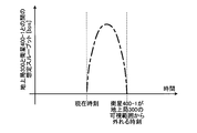
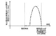
- the figure which shows the example of the assumed throughput when the arithmetic unit of the scheduler device is derived and the ground station keeps pointing to the satellite which is currently pointing The figure which shows the example of the angle of departure between the satellite which is pointed at now and which is derived from the arithmetic unit of the scheduler device as seen from the ground station.
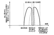
- Schematic diagram showing how the calculation unit of the scheduler device derives the switching timing of the satellites to which the ground station points
- the sequence diagram which shows the signal transmitted / received in the process which the scheduler apparatus determines the timing which switches the next pointing destination satellite of a ground station, and a pointing destination satellite The figure which shows the example in the case of comprising the processing circuit of a scheduler apparatus with CPU and memory
- FIG. 1 is a schematic diagram showing an example of a satellite system 700 configured by applying a scheduler device 100 according to an embodiment of the present invention.
- the satellite system 700 includes a scheduler device 100, a control station 200, a ground station 300, and satellites 400-1 to 400-N.
- N is a natural number of 2 or more.
- Satellites 400-1 to 400-N are communication satellites that provide communication services, optical satellites that observe the earth, or artificial satellites such as SAR satellites.
- the satellites 400-1 to 400-N are orbiting satellites that orbit the satellite orbits 500-1 and 500-2.
- the satellite 400-1 irradiated with the beam 600 from the ground station 300 can transmit data to the ground station 300.
- the satellites 400-1 to 400-N may be referred to as the satellite 400 when not distinguished from each other, and the satellite orbits 500-1 and 500-2 may be referred to as the satellite orbit 500 when not distinguished from each other.
- the ground station 300, the control station 200, and the scheduler device 100 are separate devices, but may be realized by one device.
- the configuration of the satellite system 700 illustrated in FIG. 1 is an example, and the number of satellites 400, the number of satellite orbits 500, and the number of ground stations 300 are not limited to the configuration illustrated in FIG.
- the satellite system 700 may include a data relay satellite on a geostationary orbit, and the data relay satellite may relay a data signal transmitted from the satellite 400 and transmit the data signal to the ground station 300.
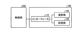
- FIG. 2 is a block diagram showing a configuration example of the scheduler device 100 according to the present embodiment.
- the scheduler device 100 includes an interface 110 that transmits and receives information to and from the control station 200 that exists outside the scheduler device 100, a calculation unit 120 that determines the satellite 400 that the ground station 300 points to, and a storage unit 130 that stores information. .
- the scheduler apparatus 100 determines the satellite 400 that the ground station 300 points to, that is, the satellite 400 with which the ground station 300 communicates.
- the control station 200 controls the ground station 300 and the satellite 400.
- the control station 200 transmits control information such as scheduling information output from the scheduler device 100 to the ground station 300 and the satellite 400.
- FIG. 3 is a block diagram showing a configuration example of the satellite 400-1 according to the present embodiment. Since the satellites 400-1 to 400-N have the same configuration, the satellite 400-1 will be described as an example.
- the satellite 400-1 includes receiving antennas 401-1 to 401-4 that receive signals from the ground station 300 or a terminal on the ground (not shown), and a transmission antenna 402-1 that transmits signals to the ground station 300 or a terminal on the ground (not shown). , And a telemetry signal transmitting antenna 403 for transmitting a telemetry signal indicating the internal state of the satellite 400-1.
- the satellite 400-1 also includes phase shifters 404-1 to 404-4 that adjust the phases of signals transmitted from the transmission antennas 402-1 to 402-4, reception antennas 401-1 to 401-4, and a transmission antenna 402. -1 to 402-4, a repeater 405 that relays a signal, and a telemetry signal generation unit 406 that generates a telemetry signal.
- the satellite 400-1 also includes a buffer 407 that temporarily stores signals received by the receiving antennas 401-1 to 401-4, and a control unit 408 that controls the repeater 405 and the phase shifters 404-1 to 404-4. And comprising.
- the receiving antennas 401-1 to 401-4 are not distinguished, they are referred to as the receiving antenna 401.
- the transmitting antennas 402-1 to 402-4 are not distinguished, they are referred to as the transmitting antenna 402
- the phase shifter 404-1. .., 404-4 may be referred to as phase shifter 404 when not distinguished.
- the repeater 405 includes a filter, an amplifier, a duplexer, a switch, a multiplexer, and the like.
- the repeater 405 may further include a modulator and a demodulator in addition to the above-described filter, and may be configured to enable regenerative relay.
- the repeater 405 is an existing satellite-mounted repeater.
- the buffer 407 is not an essential component.
- the satellite 400-1 is a communication satellite and there is no need to store a signal received by the reception antenna 401
- the satellite 400-1 is configured to directly connect the reception antenna 401 and the repeater 405. Also good.
- the case where the satellite 400-1 includes the buffer 407 will be described as an example.
- the space between the satellite 400 and the ground station 300 and the space between the satellite 400 and the data relay satellite may be an optical line, or may be configured to include both an optical line and a wireless line.
- the configuration of each device varies depending on the form of the line between the devices, but in this embodiment, the form of the line between the devices is not particularly limited.
- the transmission antenna 402 is a phased array antenna.
- the satellite 400-1 can change the irradiation direction of the signal transmitted from the transmission antenna 402, that is, the phased array antenna, by controlling the phase of the signal transmitted from the transmission antenna 402 by the phase shifter 404.
- Satellite 400-1 includes a normal antenna and a movable reflecting mirror instead of transmitting antenna 402, that is, phased array antenna and phase shifter 404, and transmits from the normal antenna by changing the direction of the reflecting mirror.
- the structure which changes the irradiation direction of a signal may be sufficient.
- the control unit 408 changes the irradiation direction of the signal to be transmitted by controlling the phase shifter 404 in accordance with a control signal transmitted from the ground station 300, for example, a control signal instructing the irradiation direction of the signal transmitted from the transmission antenna 402 or the like. To do.
- the telemetry signal generation unit 406 generates, as internal information of the satellite 400-1, for example, data accumulation amount information indicating the amount of data accumulated in the buffer 407.
- the telemetry signal generation unit 406 transmits the generated telemetry signal including the internal information of the satellite 400-1 from the telemetry signal transmission antenna 403 to the ground station 300.
- the telemetry signal generation unit 406 may generate data type information indicating the type of data stored in the buffer 407 as internal information, and transmit the data type information included in the telemetry signal.
- the telemetry signal generation unit 406 may transmit two pieces of information including the data accumulation amount and the data type included in the telemetry signal.
- the scheduler device 100 transmits the data stored in the buffer 407 included in the telemetry signal transmitted from the satellite 400 and acquired via the ground station 300 and the control station 200, and the coordinate data of all the satellites 400 stored in the storage unit 130 in advance. , Etc., to determine the satellite 400 to which the ground station 300 points.
- scheduler apparatus 100 is configured so that ground station 300 is directed to satellite 400 and ground station 300 is directed to satellite 400 so that the throughput of data received by ground station 300 from satellite 400 is maximized. Determine the timing for switching.
- the scheduler apparatus 100 generates a control signal including a pointing destination satellite 400 of the ground station 300 and a switching timing at which the ground station 300 switches the pointing destination satellite 400, and transmits the control signal to the ground station 300.
- the ground station 300 uses the control signal received by itself and transmits the control signal to the satellite 400.
- the scheduler device 100 may not store the coordinate data of the satellite 400 in the storage unit 130 in advance.
- the scheduler device 100 acquires the telemetry signal from the ground station 300 via the control station 200, and telemetry The coordinate data of the satellite 400 may be acquired from the signal.
- the method by which the scheduler apparatus 100 obtains the coordinate data of the satellite 400 is not limited to these, and may be in an appropriate format according to the implementation.
- control signal indicating the satellite 400 to which the ground station 300 points the control signal for controlling the phase shifter 404 of the satellite 400, the control signal for controlling the direction of the reflector of the satellite 400, and the like.
- a suitable format may be selected according to the configuration of the satellite 400.
- the scheduler device 100 determines the satellite 400 to be the next pointing destination when the ground station 300 switches the pointing destination satellite 400, and the ground station 300 determines the pointing destination satellite 400. It is a flowchart which shows an example of the process which determines the timing which switches. The flowchart illustrated in FIG. 4 is an example, and the scheduler device 100 may perform each process in a different order within a range in which an equivalent process result is obtained.
- the arithmetic unit 120 first acquires the position information of the satellites 400-1 to 400-M stored in advance from the storage unit 130 (step S1001). As described above, the arithmetic unit 120 may acquire a telemetry signal from the ground station 300 and acquire position information of the satellites 400-1 to 400-M from the telemetry signal.
- M is a natural number greater than or equal to 2 and less than or equal to N, in which the number of satellites 400 orbiting the visible range of the ground station 300 is M ⁇ 1 before the satellite 400-1 is out of the visible range in the ground station 300. It is.
- the ground station 300 orbits the visible range of the ground station 300 until the satellite 400-1 is out of the visible range.
- the satellites 400 are satellites 400-2 to 400-M.
- Satellite 400-1 is the first orbiting satellite
- satellites 400-2 to 400-M are the second orbiting satellite candidates
- ground station 300 of satellites 400-2 to 400-M is satellite 400-1.
- the pointing satellite 400 is set as the second orbiting satellite.
- the ground station 300 receives the telemetry signal received from the satellites 400-1 to 400-M.
- the arithmetic unit 120 acquires the data accumulation amount of the buffer 407 in the satellites 400-1 to 400-M from the ground station 300 (step S1002).
- the calculation unit 120 acquires the rain attenuation amount at the ground station 300 (step S1003). There are various methods for the calculation unit 120 to acquire the rain attenuation amount.
- the computing unit 120 derives the rain attenuation amount based on, for example, the rainfall information around the ground station 300 stored in advance in the storage unit 130 and the elevation angle of the ground station 300 that is directed to the satellite 400-1.
- the rain attenuation amount may be derived from a pilot signal for notifying the rain condition transmitted from the satellite 400-1 to the ground station 300.
- the arithmetic unit 120 can visually recognize the satellite 400-1 currently pointed at the ground station 300.
- An assumed throughput is derived when the direction is continued until it is out of the range (step S1004).
- FIG. 5 is a diagram showing an example of the assumed throughput when the ground station 300 continues to point to the satellite 400-1 to which the ground station 300 currently points, derived by the arithmetic unit 120 of the scheduler device 100 according to the present embodiment.
- the horizontal axis indicates time
- the vertical axis indicates the size of throughput.
- the period for deriving the assumed throughput when the ground station 300 continues to point to the satellite 400-1 in the arithmetic unit 120 is the time from the current time until the satellite 400-1 goes out of the visible range of the ground station 300.
- the calculation unit 120 stores the derived estimated throughput in the storage unit 130.
- the arithmetic unit 120 determines the timing for switching the pointing destination from the satellite 400-1 to which the ground station 300 is currently pointing to another satellite 400, here, the satellites 400-2 to 400-M. ).
- Loop 1 is a process in which the arithmetic unit 120 repeats the number of satellites 400 that pass through the visible range of the ground station 300 before the satellite 400-1 moves out of the visible range of the ground station 300, in this case, M-1 times.
- the calculation unit 120 selects one satellite 400-m from the satellites 400-2 to 400-M when starting the processing of the loop 1.
- m is a natural number of 2 or more and M or less.
- the computing unit 120 derives the angle between the satellite 400-1 viewed from the ground station 300 and the selected satellite 400-m (step S1005).
- FIG. 6 shows an example of the angle of separation between the currently oriented satellite 400-1 and the selected satellite 400-m, as viewed from the ground station 300, derived by the arithmetic unit 120 of the scheduler apparatus 100 according to the present embodiment.
- FIG. 6 the horizontal axis represents time, and the vertical axis represents the magnitude of the angle of separation between the satellite 400-1 and the satellite 400-m as viewed from the ground station 300.
- the time when the angle of separation becomes the minimum means the time when the satellite 400-1 and the satellite 400-m are closest.
- the time at which the angle of separation is minimized is the time at which the time required for switching the pointing destination is shortest when the ground station 300 changes the pointing destination from the satellite 400-1 to the satellite 400-m.
- the calculation unit 120 stores the derived separation angle in the storage unit 130. Note that the calculation unit 120 may use the position information of the satellites 400-1 to 400-M stored in advance in the storage unit 130 when calculating the angle of departure, or the satellites 400-1 to 400- included in the telemetry signal. 400-M position information may be used.
- the calculation unit 120 assumes that the ground station 300 points to the satellite 400-m based on the position information of the satellite 400-m, the elevation angle of the ground station 300 obtained from the position information, and the rain attenuation amount of the ground station 300. Throughput is derived (step S1006).
- FIG. 7 is a diagram showing an example of the assumed throughput when the ground station 300 points to the satellite 400-m selected by the arithmetic unit 120 of the scheduler device 100 according to the present embodiment.
- the calculation unit 120 stores the derived estimated throughput in the storage unit 130. Note that since the ground station 300 is currently directed to the satellite 400-1, the ground station 300 cannot directly receive a pilot signal for notifying the rain condition from the satellite 400-m. Therefore, the calculation unit 120 determines the rain attenuation amount when the ground station 300 points to the satellite 400-m, the rain state included in the pilot signal received by the ground station 300 from the satellite 400-1, and the satellite 400-1. It may be obtained from the angle of separation with the satellite 400-m, or may be obtained from the rainfall information stored in advance in the storage unit 130 and the angle of separation between the satellite 400-1 and the satellite 400-m.
- the calculation unit 120 calculates the assumed throughput when the ground station 300 derived in step S1004 continues to point to the satellite 400-1, the separation angle between the satellite 400-1 and the satellite 400-m derived in step S1005, and the step Based on the assumed throughput when the ground station 300 derived in S1006 points to the satellite 400-m, the timing for switching the destination satellite 400 that maximizes the throughput of the ground station 300 is derived (step S1007).
- the calculation unit 120 derives the switching timing of the pointing destination satellite 400, for example, the time integral value of the assumed throughput when the ground station 300 derived in step S1004 continues to point to the satellite 400-1, and the switching timing derived in step S1006.
- the arithmetic unit 120 when determining the switching timing at which the ground station 300 switches the pointing destination, the arithmetic unit 120 finally obtains the highest throughput in the ground station 300 after estimating the amount of data that the ground station 300 can receive. The timing is determined.
- FIG. 8 is a schematic diagram illustrating a method by which the calculation unit 120 of the scheduler device 100 according to the present embodiment derives the switching timing of the satellite to which the ground station 300 points.
- the thick line portion indicates the throughput obtained by the ground station 300 from the satellite 400-1 and the satellite 400-m, and the time integral value of the thick line portion is received by the ground station 300 from the satellite 400-1 and the satellite 400-m.
- the total data capacity is shown.
- the time when the throughput of the ground station 300 is 0 in the bold line portion in FIG. 8 indicates that the time required for the ground station 300 to switch from the satellite 400-1 to the satellite 400-m.
- the ground station 300 cannot receive data from either the satellite 400-1 or the satellite 400-m in the time required for switching.
- the computing unit 120 derives the throughput time integral value for all possible switching timings altogether, and selects the timing at which the throughput time integral value is maximized from among them as the switching destination timing. It can be derived, but is not limited to this method. Note that the calculation unit 120 can determine the time required for switching based on the angle of departure derived in step S1005, that is, the position information of the satellite 400-1 and the satellite 400-m.
- the calculation unit 120 selects the unselected satellite 400-m from the satellites 400-2 to 400-M.
- the arithmetic unit 120 performs the process of loop 1 for all the candidates for the satellite 400 to which the ground station 300 is directed next, that is, the satellite 400-2 to the satellite 400-M.
- the arithmetic unit 120 derives the switching timing at which the throughput of the ground station 300 is maximized for each of the satellites 400-2 to 400-M and the maximum throughput obtained when the pointing destination satellite 400 is switched at the switching timing. .
- the arithmetic unit 120 obtains the candidates for the next destination satellite 400 obtained by the loop 1 processing, that is, the satellites 400-2 to 400-M. Based on the switching timing and the maximum throughput for each of the satellites 400-2 to 400-M, the ground station 300 determines the switching destination satellite 400 that switches the pointing destination from the satellite 400-1 (step S1008).
- the calculation unit 120 determines the time required for the ground station 300 to switch from the satellite 400-1 to the satellites 400-2 to 400-M in the processing of loop 1 and step S1008.
- the station 300 determines the switching timing for switching the pointing destination from the satellite 400-1 to the next pointing satellite 400.
- the calculation unit 120 can determine the next pointing destination satellite 400 and the switching timing by various methods. For example, the arithmetic unit 120 may simply select the satellite 400 with the highest throughput and the switching timing to the satellite 400. In addition, based on the data accumulation amount of the buffer 407 for each satellite 400 acquired in step S1002, the calculation unit 120 may select the satellite 400 with the largest data accumulation amount as the next pointing destination satellite 400. The calculation unit 120 determines the satellite 400 to be directed in consideration of the data accumulation amount of the buffer 407 of each satellite 400. In addition, when the data type information is included in the telemetry signal and the priority is classified according to the data type, the arithmetic unit 120 relays data with high priority based on the data type. 400 may be selected as the next pointing destination satellite 400.
- the calculation unit 120 determines the satellite 400 to be directed in consideration of the priority of data stored in the buffer 407 of each satellite 400.
- the arithmetic unit 120 may select the satellite 400 to which the ground station 300 is directed next by using a plurality of elements of the above-described throughput size, data accumulation amount, and data type.
- the computing unit 120 generates a control signal including the timing of switching to the next pointing destination satellite 400 and the next pointing destination satellite 400 of the ground station 300 selected in step S1008 (step S1009).
- the control signal is a signal for instructing the irradiation angle of the satellite 400 and the ground station 300, for example.
- the arithmetic unit 120 can generate the next pointing destination satellite 400 of the ground station 300 and the switching timing information in the form of control information that determines the direction of the beam directed by the satellite 400 and the ground station 300 for each time. .
- the interface 110 transmits the control signal generated by the calculation unit 120 in step S1009 to the ground station 300 and the satellites 400-1 to 400-M (step S1010).
- the interface 110 may transmit a control signal to the ground station 300 via the control station 200 through a ground line or the like. Further, the interface 110 may transmit the control signal for the satellite 400-1 via the ground station 300 that is directed to the satellite 400-1.
- the interface 110 transmits a control signal for the satellites 400-2 to 400-M via the ground station when there is a ground station other than the ground station 300 that points to the satellites 400-2 to 400-M. Also good.
- the satellite system 700 has a network configuration including a data relay satellite (not shown in FIG.
- the interface 110 may transmit a control signal to the satellites 400-2 to 400-M via the data relay satellite.
- the interface 110 can transmit control signals in various ways depending on the network configuration of the satellite system 700.
- the processing of the calculation unit 120 is referred to as a calculation step, and the processing of the interface 110 is referred to as a transmission step.
- FIG. 9 is a sequence diagram illustrating signals transmitted and received in the process in which the scheduler device 100 according to the first embodiment determines the timing for switching the next pointing destination satellite 400 and the pointing destination satellite 400 of the ground station 300. .
- the processing of the flowchart shown in FIG. 4 can be executed by the scheduler device 100 according to the sequence diagram shown in FIG. 9, but is not limited to this.
- the scheduler device 100 determines the next pointing destination satellite 400 of the ground station 300 and the switching timing immediately after acquiring the position information and the rain attenuation information, and generates a control signal.
- the control signal may be generated by determining the satellite 400 that is the next pointing destination of the ground station 300 and the switching timing in a cycle.
- the calculation unit 120 considers only one switching destination of the satellite 400 to which the ground station 300 is directed in the above-described processing, but is not limited thereto. In an environment where the amount of rain attenuation is small due to clear weather or the like, the calculation unit 120 considers the second or third switching destination of the satellite 400 to which the ground station 300 is directed, and takes the ground station 300 into account. The switching destination satellite 400 and switching timing may be determined so that the throughput is maximized.
- the satellite system 700 may include a plurality of ground stations 300 as described above.
- the calculation unit 120 calculates the rain attenuation amount at the plurality of ground stations 300 based on the rainfall state information included in the pilot signal received from the satellite 400.
- the ground station 300 having a small amount of rainfall attenuation may be determined as the ground station 300 to which the data of the satellite 400 is transmitted. Thereby, when there are a plurality of ground stations 300, the satellite 400 can transmit data to the ground station 300 with a small amount of rainfall attenuation.
- the interface 110 is realized by an interface circuit or the like.
- the interface circuit is, for example, a network interface card.
- the storage unit 130 is realized by a memory.
- the arithmetic unit 120 is realized by a processing circuit. That is, the scheduler device 100 includes a processing circuit for determining the timing of switching the satellite 400 that is the next pointing destination of the ground station 300 and the satellite 400 that is the pointing destination.
- the processing circuit may be a CPU (Central Processing Unit) and a memory that execute a program stored in the memory, or may be dedicated hardware.
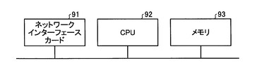
- FIG. 10 is a diagram illustrating an example in which the processing circuit of the scheduler device 100 according to the first embodiment is configured by a CPU and a memory.
- the network interface card 91 implements the interface 110 described above.
- each function of the processing circuit of the scheduler device 100 is realized by software, firmware, or a combination of software and firmware.
- Software or firmware is described as a program and stored in the memory 93.
- each function is realized by the CPU 92 reading and executing the program stored in the memory 93. That is, in the scheduler device 100, the processing circuit stores a program that will be executed as a result of determining the timing for switching the next pointing destination satellite 400 and the pointing destination satellite 400 of the ground station 300.
- the memory 93 is provided. These programs can also be said to cause a computer to execute the procedure and method of the scheduler device 100.
- the CPU 92 may be a processing device, an arithmetic device, a microprocessor, a microcomputer, a processor, or a DSP (Digital Signal Processor).
- the memory 93 is a nonvolatile or volatile semiconductor memory such as RAM (Random Access Memory), ROM (Read Only Memory), flash memory, EPROM (Erasable Programmable ROM), EEPROM (Electrically EPROM), etc. Magnetic disks, flexible disks, optical disks, compact disks, mini disks, DVDs (Digital Versatile Discs), etc. are applicable.
- the memory 93 may be common with the memory that implements the storage unit 130.
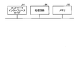
- FIG. 11 is a diagram illustrating an example in which the treatment circuit of the scheduler device 100 according to the first embodiment is configured with dedicated hardware.
- the processing circuit is dedicated hardware
- the processing circuit 94 shown in FIG. 11 includes, for example, a single circuit, a composite circuit, a programmed processor, a parallel programmed processor, an ASIC (Application Specific Integrated Circuit), an FPGA ( Field Programmable Gate Array) or a combination of these.
- Each function of the scheduler device 100 may be realized by the processing circuit 94 for each function, or each function may be realized by the processing circuit 94 collectively.
- each function of the scheduler device 100 may be realized by dedicated hardware and a part may be realized by software or firmware.
- the processing circuit can realize the above-described functions by dedicated hardware, software, firmware, or a combination thereof.
- calculation unit 120 maximizes the throughput of ground station 300 based on the position information of satellite 400 and the amount of rainfall attenuation at ground station 300.
- the next satellite 400 to which the ground station 300 is directed and the timing for switching the pointing destination to the next satellite 400 are determined.
- the ground station 300 can be efficiently operated in the satellite system 700 composed of a plurality of orbiting satellites.
- the ground station 300 can efficiently communicate with the satellite 400 to which it is directed.
- the configuration described in the above embodiment shows an example of the contents of the present invention, and can be combined with another known technique, and can be combined with other configurations without departing from the gist of the present invention. It is also possible to omit or change the part.
Landscapes
- Engineering & Computer Science (AREA)
- Computer Networks & Wireless Communication (AREA)
- Signal Processing (AREA)
- Physics & Mathematics (AREA)
- Astronomy & Astrophysics (AREA)
- Aviation & Aerospace Engineering (AREA)
- General Physics & Mathematics (AREA)
- Radio Relay Systems (AREA)
Abstract
Description
図1は、本発明の実施の形態にかかるスケジューラ装置100を適用して構成される衛星システム700の例を示す模式図である。衛星システム700は、スケジューラ装置100と、制御局200と、地上局300と、衛星400-1~400-Nと、を備える。Nは2以上の自然数である。衛星400-1~400-Nは、通信サービスを提供する通信衛星、地球を観測する光学衛星、またはSAR衛星などの人工衛星である。また、衛星400-1~400-Nは、衛星軌道500-1,500-2のいずれかの軌道上を周回している周回衛星である。図1では、衛星400-1~400-Nのうち、地上局300からビーム600で照射された衛星400-1が、地上局300へデータを送信することができる。以降の説明において、衛星400-1~400-Nを区別しない場合は衛星400と称し、衛星軌道500-1,500-2を区別しない場合は衛星軌道500と称することがある。
Claims (13)
- 地上局が現在指向している周回衛星である第1の周回衛星から次に指向する周回衛星である第2の周回衛星の候補の周回衛星である第2の周回衛星候補への切り替えに要する時間、前記地上局と前記第1の周回衛星との間の将来の想定スループット、および前記地上局と前記第2の周回衛星候補との間の将来の想定スループットに基づいて、前記第2の周回衛星、および前記地上局が指向先を前記第1の周回衛星から前記第2の周回衛星に切り替える切り替えタイミングを決定する演算部と、
前記演算部で決定された前記第2の周回衛星および前記切り替えタイミングの情報を送信するインターフェースと、
を備えることを特徴とするスケジューラ装置。 - 前記演算部は、前記地上局と前記周回衛星との間の将来の想定スループットを、前記周回衛星の位置情報、および前記地上局における前記周回衛星毎の降雨減衰量に基づいて決定する、
ことを特徴とする請求項1に記載のスケジューラ装置。 - 前記演算部は、前記切り替えに要する時間を、前記第1の周回衛星の位置情報および前記第2の周回衛星候補の位置情報に基づいて決定する、
ことを特徴とする請求項1または2に記載のスケジューラ装置。 - 前記インターフェースは、前記第2の周回衛星および前記切り替えタイミングの情報を、前記周回衛星および前記地上局が指向するビームの方向を時間ごとに定める制御情報として送信する、
ことを特徴とする請求項1から3のいずれか1つに記載のスケジューラ装置。 - さらに、降雨量の情報を保存する記憶部を備え、
前記演算部は、前記降雨量の情報および前記地上局の前記周回衛星に対する仰角に基づいて、前記地上局における前記周回衛星毎の前記降雨減衰量を導出する、
ことを特徴とする請求項2に記載のスケジューラ装置。 - 前記演算部は、前記地上局が前記第1の周回衛星から受信したパイロット信号に含まれる降雨状態の情報、および前記地上局の前記周回衛星に対する仰角に基づいて、前記地上局における前記周回衛星毎の降雨減衰量を導出する、
ことを特徴とする請求項2に記載のスケジューラ装置。 - 前記演算部は、前記地上局と前記第1の周回衛星との間の前記将来の想定スループットの時間積分値、および前記地上局と前記第2の周回衛星候補との間の前記将来の想定スループットの時間積分値に基づいて、前記切り替えタイミングを導出する、
ことを特徴とする請求項1から6のいずれか1つに記載のスケジューラ装置。 - 前記演算部は、前記地上局と前記第1の周回衛星との間の前記将来の想定スループットの時間積分値、および前記地上局と前記第2の周回衛星候補との間の前記将来の想定スループットの時間積分値の合計値が最大となるタイミングを、前記切り替えタイミングとして導出する、
ことを特徴とする請求項7に記載のスケジューラ装置。 - 前記演算部は、前記第2の周回衛星候補が送信したテレメトリ信号に含まれる、前記第2の周回衛星候補のバッファに蓄積されているデータの量を示すデータ蓄積量に基づいて、前記第2の周回衛星を決定する、
ことを特徴とする請求項8に記載のスケジューラ装置。 - 前記演算部は、前記第2の周回衛星候補が送信したテレメトリ信号に含まれる、前記第2の周回衛星候補のバッファに蓄積されているデータの種別を示すデータ種別に基づいて、前記第2の周回衛星を決定する、
ことを特徴とする請求項8に記載のスケジューラ装置。 - 前記演算部は、前記地上局と前記第1の周回衛星との間の前記将来の想定スループットの時間積分値、および前記地上局と前記第2の周回衛星候補との間の前記将来の想定スループットの時間積分値の最大合計値を前記第2の周回衛星候補毎に導出し、前記最大合計値が最大となる前記第2の周回衛星候補を、前記第2の周回衛星として決定する、
ことを特徴とする請求項8に記載のスケジューラ装置。 - 複数の地上局を含むネットワークの形態において、
前記演算部は、前記周回衛星から受信したパイロット信号に含まれる降雨状態の情報に基づいて前記複数の地上局における降雨減衰量を導出し、前記周回衛星のデータの送信先の地上局として降雨減衰量の少ない地上局を決定する、
ことを特徴とする請求項8に記載のスケジューラ装置。 - 演算部が、
地上局が現在指向している周回衛星である第1の周回衛星から次に指向する周回衛星である第2の周回衛星の候補の周回衛星である第2の周回衛星候補への切り替えに要する時間、前記地上局と前記第1の周回衛星との間の将来の想定スループット、および前記地上局と前記第2の周回衛星候補との間の将来の想定スループットに基づいて、前記第2の周回衛星、および前記地上局が指向先を前記第1の周回衛星から前記第2の周回衛星に切り替える切り替えタイミングを決定する演算ステップと、
インターフェースが、前記演算ステップにおいて決定された前記第2の周回衛星および前記切り替えタイミングの情報を送信する送信ステップと、
を含むことを特徴とするスケジューリング方法。
Priority Applications (5)
| Application Number | Priority Date | Filing Date | Title |
|---|---|---|---|
| EP17895421.0A EP3567748B1 (en) | 2017-02-06 | 2017-02-06 | Scheduler device and scheduling method |
| PCT/JP2017/004240 WO2018142618A1 (ja) | 2017-02-06 | 2017-02-06 | スケジューラ装置およびスケジューリング方法 |
| CA3050860A CA3050860C (en) | 2017-02-06 | 2017-02-06 | Scheduler apparatus and scheduling method |
| US16/476,355 US10727935B2 (en) | 2017-02-06 | 2017-02-06 | Scheduler apparatus and scheduling method |
| JP2018565228A JP6524361B2 (ja) | 2017-02-06 | 2017-02-06 | スケジューラ装置およびスケジューリング方法 |
Applications Claiming Priority (1)
| Application Number | Priority Date | Filing Date | Title |
|---|---|---|---|
| PCT/JP2017/004240 WO2018142618A1 (ja) | 2017-02-06 | 2017-02-06 | スケジューラ装置およびスケジューリング方法 |
Publications (1)
| Publication Number | Publication Date |
|---|---|
| WO2018142618A1 true WO2018142618A1 (ja) | 2018-08-09 |
Family
ID=63039444
Family Applications (1)
| Application Number | Title | Priority Date | Filing Date |
|---|---|---|---|
| PCT/JP2017/004240 Ceased WO2018142618A1 (ja) | 2017-02-06 | 2017-02-06 | スケジューラ装置およびスケジューリング方法 |
Country Status (5)
| Country | Link |
|---|---|
| US (1) | US10727935B2 (ja) |
| EP (1) | EP3567748B1 (ja) |
| JP (1) | JP6524361B2 (ja) |
| CA (1) | CA3050860C (ja) |
| WO (1) | WO2018142618A1 (ja) |
Cited By (2)
| Publication number | Priority date | Publication date | Assignee | Title |
|---|---|---|---|---|
| WO2020106659A1 (en) * | 2018-11-20 | 2020-05-28 | Hughes Network Systems, Llc | Satellite load balancing |
| JP2024045462A (ja) * | 2019-12-06 | 2024-04-02 | キヤノン電子株式会社 | 衛星追尾システム |
Families Citing this family (2)
| Publication number | Priority date | Publication date | Assignee | Title |
|---|---|---|---|---|
| US20210320715A1 (en) * | 2020-04-10 | 2021-10-14 | John Moroney | Hybrid dual-band satellite communication system |
| CN114476131B (zh) * | 2021-11-09 | 2023-03-10 | 浙江时空道宇科技有限公司 | 一种卫星测控调度方法、装置及存储介质 |
Citations (4)
| Publication number | Priority date | Publication date | Assignee | Title |
|---|---|---|---|---|
| JP2000513912A (ja) * | 1997-04-25 | 2000-10-17 | モトローラ・インコーポレイテッド | 通信の妨害環境に対処する方法および装置 |
| JP2001506465A (ja) * | 1997-05-02 | 2001-05-15 | ユーエスシーエックス | 高緯度静止衛星システム |
| JP2003318794A (ja) * | 2002-04-26 | 2003-11-07 | Hitachi Ltd | 人工衛星からの信号の受信方法,人工衛星からの信号の受信装置,送信方法及び人工衛星と情報を授受する情報システム |
| JP2004140721A (ja) | 2002-10-21 | 2004-05-13 | Hitachi Ltd | 人工衛星を利用した信号の受信方法、サービスの提供方法、人工衛星の制御方法、および受信端末ならびに人工衛星を制御する装置 |
Family Cites Families (15)
| Publication number | Priority date | Publication date | Assignee | Title |
|---|---|---|---|---|
| US6377208B2 (en) * | 1997-02-21 | 2002-04-23 | Hughes Electronics Corporation | Method and system for determining a position of a transceiver unit utilizing two-way ranging in a polystatic satellite configuration |
| JP2000315972A (ja) * | 1999-05-06 | 2000-11-14 | Nec Corp | 衛星通信システム及びそのハンドオーバ処理方法 |
| KR100705579B1 (ko) * | 2005-08-01 | 2007-04-10 | 삼성전자주식회사 | 복합망을 이용한 핸드오프 구현 시스템 및 그 방법 |
| US20070135040A1 (en) * | 2005-12-12 | 2007-06-14 | Draim John E | Methods for effecting seamless handover and enhancing capacity in elliptical orbit satellite communications systems |
| JP2014053751A (ja) * | 2012-09-07 | 2014-03-20 | Takeshi Hatsuda | 複数衛星間の動的切り替えを行うサテライトダイバーシティ(D・Sat−D)方式 |
| US8712321B1 (en) * | 2013-01-07 | 2014-04-29 | Viasat, Inc. | Satellite fleet deployment |
| EP3120467B1 (en) * | 2014-03-19 | 2019-02-20 | Hughes Network Systems, LLC | Apparatus and method for efficient handover for low earth orbit (leo) satellite systems |
| US20170127323A1 (en) * | 2014-04-27 | 2017-05-04 | Novelsat Ltd. | Handover between satellites using a single modem |
| US9888426B2 (en) | 2015-05-01 | 2018-02-06 | Qualcomm Incorporated | Handoff for satellite communication |
| WO2017048339A1 (en) * | 2015-06-16 | 2017-03-23 | King Abdulaziz City Of Science And Technology | Systems and methods for remote sensing of the earth from space |
| US10177837B2 (en) * | 2015-06-17 | 2019-01-08 | Hughes Network Systems, Llc | Approaches for high speed global packet data services for LEO/MEO satellite systems |
| US9681337B2 (en) * | 2015-08-05 | 2017-06-13 | Qualcomm Incorporated | Satellite-to-satellite handoff in satellite communications system |
| US10476583B2 (en) * | 2015-08-13 | 2019-11-12 | Viasat, Inc. | Managed time division duplexed baseband signaling |
| US10244453B2 (en) * | 2015-10-13 | 2019-03-26 | Qualcomm Incorporated | Method and apparatus for inter-satellite handovers in low-earth orbit (LEO) satellite systems |
| JP6937750B2 (ja) * | 2015-10-28 | 2021-09-22 | ワールドビュー・サテライツ・リミテッド | 増大した通信容量を有する衛星システムおよび衛星システムの容量を増大させるための方法 |
-
2017
- 2017-02-06 EP EP17895421.0A patent/EP3567748B1/en active Active
- 2017-02-06 WO PCT/JP2017/004240 patent/WO2018142618A1/ja not_active Ceased
- 2017-02-06 CA CA3050860A patent/CA3050860C/en active Active
- 2017-02-06 US US16/476,355 patent/US10727935B2/en active Active
- 2017-02-06 JP JP2018565228A patent/JP6524361B2/ja active Active
Patent Citations (4)
| Publication number | Priority date | Publication date | Assignee | Title |
|---|---|---|---|---|
| JP2000513912A (ja) * | 1997-04-25 | 2000-10-17 | モトローラ・インコーポレイテッド | 通信の妨害環境に対処する方法および装置 |
| JP2001506465A (ja) * | 1997-05-02 | 2001-05-15 | ユーエスシーエックス | 高緯度静止衛星システム |
| JP2003318794A (ja) * | 2002-04-26 | 2003-11-07 | Hitachi Ltd | 人工衛星からの信号の受信方法,人工衛星からの信号の受信装置,送信方法及び人工衛星と情報を授受する情報システム |
| JP2004140721A (ja) | 2002-10-21 | 2004-05-13 | Hitachi Ltd | 人工衛星を利用した信号の受信方法、サービスの提供方法、人工衛星の制御方法、および受信端末ならびに人工衛星を制御する装置 |
Cited By (4)
| Publication number | Priority date | Publication date | Assignee | Title |
|---|---|---|---|---|
| WO2020106659A1 (en) * | 2018-11-20 | 2020-05-28 | Hughes Network Systems, Llc | Satellite load balancing |
| US10863404B2 (en) | 2018-11-20 | 2020-12-08 | Hughes Network Systems, Llc | Satellite load balancing |
| JP2024045462A (ja) * | 2019-12-06 | 2024-04-02 | キヤノン電子株式会社 | 衛星追尾システム |
| JP7659671B2 (ja) | 2019-12-06 | 2025-04-09 | キヤノン電子株式会社 | 衛星追尾システム |
Also Published As
| Publication number | Publication date |
|---|---|
| JP6524361B2 (ja) | 2019-06-05 |
| EP3567748B1 (en) | 2021-03-24 |
| US20200044731A1 (en) | 2020-02-06 |
| EP3567748A4 (en) | 2020-01-15 |
| EP3567748A1 (en) | 2019-11-13 |
| JPWO2018142618A1 (ja) | 2019-07-11 |
| US10727935B2 (en) | 2020-07-28 |
| CA3050860A1 (en) | 2018-08-09 |
| CA3050860C (en) | 2019-12-24 |
Similar Documents
| Publication | Publication Date | Title |
|---|---|---|
| JP6524361B2 (ja) | スケジューラ装置およびスケジューリング方法 | |
| EP3332489B1 (en) | Satellite-to-satellite handoff in satellite communications system | |
| Singh et al. | A community-driven approach to democratize access to satellite ground stations | |
| US20230291469A1 (en) | Satellite communications network, satellite terminal and operation method | |
| RU2660952C2 (ru) | Системы спутников на наклонных орбитах | |
| JP2018531531A6 (ja) | 衛星通信システムにおける衛星間のハンドオフ | |
| JP2016511719A (ja) | 地球から電磁エネルギーに関する情報を得るための、例えば地球に干渉源を探すための、装置、システム、及び方法 | |
| US20170010341A1 (en) | Tracking system, tracking method, and non-transitory computer-readable recording medium storing program | |
| US20260039374A1 (en) | Communication control apparatus, communication control method, communication control program, communication control system, communication relay satellite, and satellite system | |
| EP4233205A1 (en) | Tracking non-geo synchronous orbit satellites on orbiting planes of regular motion patterns | |
| AU2017218619B2 (en) | Antenna array for aeronautical communications | |
| US20260019146A1 (en) | Earth station, relay satellite, satellite system and communication method | |
| US11260996B2 (en) | Lunar orbiting satellite system, and ground station of lunar orbiting satellite system | |
| WO2025123992A1 (zh) | 一种信号光发送方法、接收方法、装置、设备及介质 | |
| CN115224486A (zh) | 一种基于相控阵天线的对星跟踪方法及系统 | |
| CN115039353A (zh) | 指向方向控制装置、光通信终端、光通信系统以及指向方向控制方法 | |
| JP6618446B2 (ja) | 制御装置、通信システム、制御方法、及びコンピュータプログラム | |
| JP7346183B2 (ja) | レーダ計測システム及びレーダ計測方法 | |
| CN119212022A (zh) | 低轨卫星星间切换方法及系统 | |
| WO2026053619A1 (ja) | 情報処理装置、情報処理方法、及びプログラム | |
| JP2004088563A (ja) | 通信衛星システム | |
| WO2023181251A1 (ja) | 制御装置、制御方法、及び非一時的なコンピュータ可読媒体 | |
| CN120691941A (zh) | 卫星波束追踪方法及装置 | |
| JP2009111701A (ja) | 無線通信装置及び無線通信制御方法 |
Legal Events
| Date | Code | Title | Description |
|---|---|---|---|
| 121 | Ep: the epo has been informed by wipo that ep was designated in this application |
Ref document number: 17895421 Country of ref document: EP Kind code of ref document: A1 |
|
| ENP | Entry into the national phase |
Ref document number: 2018565228 Country of ref document: JP Kind code of ref document: A |
|
| ENP | Entry into the national phase |
Ref document number: 3050860 Country of ref document: CA |
|
| NENP | Non-entry into the national phase |
Ref country code: DE |
|
| ENP | Entry into the national phase |
Ref document number: 2017895421 Country of ref document: EP Effective date: 20190808 |