WO2018143309A1 - ステアリングロック装置 - Google Patents
ステアリングロック装置 Download PDFInfo
- Publication number
- WO2018143309A1 WO2018143309A1 PCT/JP2018/003309 JP2018003309W WO2018143309A1 WO 2018143309 A1 WO2018143309 A1 WO 2018143309A1 JP 2018003309 W JP2018003309 W JP 2018003309W WO 2018143309 A1 WO2018143309 A1 WO 2018143309A1
- Authority
- WO
- WIPO (PCT)
- Prior art keywords
- gear
- main gear
- rotation
- motor
- worm
- Prior art date
- Legal status (The legal status is an assumption and is not a legal conclusion. Google has not performed a legal analysis and makes no representation as to the accuracy of the status listed.)
- Ceased
Links
Images





Classifications
-
- B—PERFORMING OPERATIONS; TRANSPORTING
- B60—VEHICLES IN GENERAL
- B60R—VEHICLES, VEHICLE FITTINGS, OR VEHICLE PARTS, NOT OTHERWISE PROVIDED FOR
- B60R25/00—Fittings or systems for preventing or indicating unauthorised use or theft of vehicles
- B60R25/01—Fittings or systems for preventing or indicating unauthorised use or theft of vehicles operating on vehicle systems or fittings, e.g. on doors, seats or windscreens
- B60R25/02—Fittings or systems for preventing or indicating unauthorised use or theft of vehicles operating on vehicle systems or fittings, e.g. on doors, seats or windscreens operating on the steering mechanism
- B60R25/021—Fittings or systems for preventing or indicating unauthorised use or theft of vehicles operating on vehicle systems or fittings, e.g. on doors, seats or windscreens operating on the steering mechanism restraining movement of the steering column or steering wheel hub, e.g. restraining means controlled by ignition switch
- B60R25/0215—Fittings or systems for preventing or indicating unauthorised use or theft of vehicles operating on vehicle systems or fittings, e.g. on doors, seats or windscreens operating on the steering mechanism restraining movement of the steering column or steering wheel hub, e.g. restraining means controlled by ignition switch using electric means, e.g. electric motors or solenoids
-
- B—PERFORMING OPERATIONS; TRANSPORTING
- B60—VEHICLES IN GENERAL
- B60R—VEHICLES, VEHICLE FITTINGS, OR VEHICLE PARTS, NOT OTHERWISE PROVIDED FOR
- B60R25/00—Fittings or systems for preventing or indicating unauthorised use or theft of vehicles
- B60R25/01—Fittings or systems for preventing or indicating unauthorised use or theft of vehicles operating on vehicle systems or fittings, e.g. on doors, seats or windscreens
- B60R25/02—Fittings or systems for preventing or indicating unauthorised use or theft of vehicles operating on vehicle systems or fittings, e.g. on doors, seats or windscreens operating on the steering mechanism
- B60R25/021—Fittings or systems for preventing or indicating unauthorised use or theft of vehicles operating on vehicle systems or fittings, e.g. on doors, seats or windscreens operating on the steering mechanism restraining movement of the steering column or steering wheel hub, e.g. restraining means controlled by ignition switch
- B60R25/0215—Fittings or systems for preventing or indicating unauthorised use or theft of vehicles operating on vehicle systems or fittings, e.g. on doors, seats or windscreens operating on the steering mechanism restraining movement of the steering column or steering wheel hub, e.g. restraining means controlled by ignition switch using electric means, e.g. electric motors or solenoids
- B60R25/02153—Fittings or systems for preventing or indicating unauthorised use or theft of vehicles operating on vehicle systems or fittings, e.g. on doors, seats or windscreens operating on the steering mechanism restraining movement of the steering column or steering wheel hub, e.g. restraining means controlled by ignition switch using electric means, e.g. electric motors or solenoids comprising a locking member radially and linearly moved towards the steering column
-
- F—MECHANICAL ENGINEERING; LIGHTING; HEATING; WEAPONS; BLASTING
- F16—ENGINEERING ELEMENTS AND UNITS; GENERAL MEASURES FOR PRODUCING AND MAINTAINING EFFECTIVE FUNCTIONING OF MACHINES OR INSTALLATIONS; THERMAL INSULATION IN GENERAL
- F16H—GEARING
- F16H19/00—Gearings comprising essentially only toothed gears or friction members and not capable of conveying indefinitely-continuing rotary motion
- F16H19/08—Gearings comprising essentially only toothed gears or friction members and not capable of conveying indefinitely-continuing rotary motion for interconverting rotary motion and oscillating motion
-
- F—MECHANICAL ENGINEERING; LIGHTING; HEATING; WEAPONS; BLASTING
- F16—ENGINEERING ELEMENTS AND UNITS; GENERAL MEASURES FOR PRODUCING AND MAINTAINING EFFECTIVE FUNCTIONING OF MACHINES OR INSTALLATIONS; THERMAL INSULATION IN GENERAL
- F16H—GEARING
- F16H25/00—Gearings comprising primarily only cams, cam-followers and screw-and-nut mechanisms
- F16H25/08—Gearings comprising primarily only cams, cam-followers and screw-and-nut mechanisms for interconverting rotary motion and reciprocating motion
- F16H25/12—Gearings comprising primarily only cams, cam-followers and screw-and-nut mechanisms for interconverting rotary motion and reciprocating motion with reciprocation along the axis of rotation, e.g. gearings with helical grooves and automatic reversal
-
- H—ELECTRICITY
- H02—GENERATION; CONVERSION OR DISTRIBUTION OF ELECTRIC POWER
- H02K—DYNAMO-ELECTRIC MACHINES
- H02K7/00—Arrangements for handling mechanical energy structurally associated with dynamo-electric machines, e.g. structural association with mechanical driving motors or auxiliary dynamo-electric machines
- H02K7/10—Structural association with clutches, brakes, gears, pulleys or mechanical starters
- H02K7/116—Structural association with clutches, brakes, gears, pulleys or mechanical starters with gears
- H02K7/1163—Structural association with clutches, brakes, gears, pulleys or mechanical starters with gears where at least two gears have non-parallel axes without having orbital motion
- H02K7/1166—Structural association with clutches, brakes, gears, pulleys or mechanical starters with gears where at least two gears have non-parallel axes without having orbital motion comprising worm and worm-wheel
Definitions
- This disclosure relates to a steering lock device.
- Patent Document 1 is provided integrally with a motor that is mounted on a frame member and rotates a motor shaft, a worm attached to the motor shaft, a gear that meshes with the worm and rotates as the worm rotates.
- a steering lock device including a cam member that rotates about the same axis as the gear and a rod that operates as the cam member rotates is disclosed.
- the motor shaft is arranged to be inclined with respect to the frame surface, and the rotation surface of the gear is also arranged to be orthogonal to the frame surface. It is.
- Patent Document 2 discloses a steering lock device in which an axial direction of a motor shaft and a rotation surface of each gear are arranged in parallel to a frame surface.
- this steering lock device since the arrangement is as described above, various components are arranged in a plane, and the entire steering lock device has a planar structure, which is advantageous in terms of space.
- This disclosure relates to a steering lock device that can be made compact.
- the steering lock device of the present disclosure includes a motor, a worm, a main gear, a cam member, and a rod.
- the motor rotates the motor shaft.
- the worm is attached to the motor shaft of the motor.
- the main gear rotates as the worm rotates.
- the cam member is provided integrally with the main gear.
- the rod has an insertion / extraction portion that is inserted into and extracted from an opening provided on the steering shaft side in accordance with the operation of the cam member accompanying the rotation of the main gear. Furthermore, when the main gear is viewed in plan along the direction of the rotation axis, at least a part of at least one of the worm and the insertion / extraction part is accommodated in the circumferential region of the main gear.
- the steering lock device of the present disclosure includes a motor, a worm, a two-stage gear, an internal gear, and a rod.
- the motor is mounted on the frame member and rotates a motor shaft extending along the flat surface portion of the frame member.
- the worm is attached to a motor shaft that is rotated by a motor and extends along the plane portion of the frame member.
- the two-stage gear includes a first gear that meshes with the worm, and a second gear that has a rotation shaft that is coaxial with the rotation shaft of the first gear, and rotates along the plane portion.
- the internal gear has internal teeth that mesh with the second gear of the two-stage gear, and rotates along the plane portion.
- the rod operates between two states, a state where the rotation of the steering shaft is restricted and a state where the restriction is released, as the internal gear rotates.
- the steering lock device of the present disclosure can be made compact.
- FIG. 3 is a top view of the partial configuration shown in FIG. 2.
- FIG. 7A is an upper perspective view of the motor cover.
- FIG. 7B is a lower perspective view of the motor cover.
- FIG.7 (c) is a C arrow directional view of FIG.7 (b). It is sectional drawing which shows the lamination
- FIG. 1 is an exploded perspective view showing details of the steering lock device according to the present embodiment
- FIG. 2 is a perspective view when the partial configurations shown in FIG. 1 are assembled together.
- 3, 4 and 5 are enlarged views showing a part of the configuration shown in FIG. 1.
- FIG. 6 is a top view of the partial configuration shown in FIG.
- the steering lock device 1 schematically includes a frame member 10, a motor 20, a worm 30, a two-stage gear 40, a main gear 50, and a cam.
- the member 60, the rod 70, the motor cover 80, the printed circuit board 90, and the cover 100 are configured.
- Such a steering lock device 1 operates the worm 30, the two-stage gear 40, the main gear 50, and the cam member 60 in accordance with the operation of the motor 20, so that the steering shaft (reference numeral SS in FIG. 10 described later)
- the rod 70 is inserted into and removed from an opening (reference O in FIG. 10 described later) of a steering post (reference SP in FIG. 10 described later).
- the steering shaft is in a locked state that restricts rotation, and when the rod 70 is pulled out, the unlocked state is released.
- a frame member 10 shown in FIG. 1 is a metal member that supports various components of the steering lock device 1, and includes a plate-like flat surface portion 11, a wall portion and a screw hole standing on the flat surface portion 11. And a screw receiving portion and the like.
- the motor 20 has a motor shaft 21 and rotates the motor shaft 21 upon receiving power supply.
- the motor 20 is mounted on the frame member 10 and is disposed so that the motor shaft 21 extends along the flat surface portion 11 of the frame member 10.
- a motor housing portion 12 (see FIG. 1) is formed in the frame member 10.
- the motor housing portion 12 includes a pair of curved walls 12 a that match the shape of the side surface 22 of the motor 20, and a front wall 12 b and a rear wall 12 c that are in contact with the front surface 23 and the rear surface 24 of the motor 20.
- An upper U-shaped groove 12 d through which the motor shaft 21 passes is formed in the front wall 12 b of the motor housing portion 12.
- a circular opening 12e is formed in the rear wall 12c of the motor housing portion 12.
- the rear surface 24 of the motor 20 has a cylindrical protrusion 24 a that holds the motor shaft 21.
- a cylindrical projecting portion 24a of the motor 20 is fitted into the circular opening 12e of the rear wall 12c.
- the worm 30 shown in FIGS. 1 and 3 is a screw-like gear made of metal or resin, and is attached to the front end side of the motor shaft 21.
- a two-stage gear 40 shown in FIG. 1 is a metal or resin gear in which a first gear 41 and a second gear 42 having different numbers of teeth have a coaxial rotating shaft 43 and are integrally provided in two stages. It is. Of the two-stage gear 40, the first gear 41 is arranged to mesh with the worm 30, and the second gear 42 is arranged to mesh with the main gear 50. The number of teeth of the first gear 41 and the second gear 42 is larger in the first gear 41 and smaller in the second gear 42.
- the two-stage gear 40 rotates along the flat surface portion 11 of the frame member 10 as the worm 30 rotates.
- the main gear 50 is a gear made of metal or resin that meshes with the second gear 42 of the two-stage gear 40, and is configured to rotate along the flat portion 11 of the frame member 10, as with the two-stage gear 40.
- the main gear 50 is formed with a large number of internal teeth, and the large number of internal teeth mesh with the second gear 42.
- the main gear accommodating portion 13 is formed in the frame member 10.
- the main gear housing portion 13 is constituted by wall portions 13a, 13b and a bottom surface 13c along the outer shape of the main gear 50, and a substantially circular groove portion is formed by the wall portions 13a, 13b and the bottom surface 13c.
- the main gear 50 is configured to fit in the groove.
- the bottom surface 13 c is parallel to the flat surface portion 11 and is formed with the same height as or different from the flat surface portion 11.
- a rotation shaft 13d of the main gear 50 protrudes upward at the center of the bottom surface 13c of the main gear housing portion 13. Because of such a configuration, the main gear 50 rotates around the rotation shaft 13d so as to slide on the rotation shaft 13d or the walls 13a and 13b. As shown in FIG.
- a rotating shaft 40 a of the two-stage gear 40 is also provided on the bottom surface 13 c of the main gear housing portion 13.
- the rotary shaft 40a is provided closer to the second wall 13b than the rotary shaft 13d, and the two-stage gear 40 rotates around the rotary shaft 40a.
- the main gear 50 shown in FIGS. 1 and 4 is an arcuate (substantially semicircular) gear having internal teeth in an arcuate shape forming a part of a circle. For this reason, the main gear 50 has a shape that secures the space 51 in the remaining portion of the circle (the portion excluding the substantially semicircular main gear 50), and the space 51 in the circumferential region 52 of the main gear 50.
- the stopper 14 (refer FIG.1 and FIG.2) can be formed in a part. As is clear from FIGS. 1 and 2, the stopper 14 is provided to protrude from the first wall portion 13 a toward the rotation shaft 13 d into the main gear housing portion 13, and is in contact with the main gear 50. It restricts excessive rotation.
- a portion extending in the radial direction of the substantially semicircular gear functions as an unlocking side stopper portion 50a and a locking side stopper portion 50b.
- the stopper 14 of the frame member 10 also has an unlocking side stopper portion 14a and a locking side stopper portion 14b (see FIG. 6).
- the cam member 60 shown in FIGS. 1 and 4 is a member that rotates along the plane portion 11 as the main gear 50 rotates.
- the cam member 60 is integrated with the main gear 50 above the main gear 50. Is provided.
- the cam member 60 includes an inclined portion 61 as shown in FIG.
- the inclined portion 61 extends along the rotation direction of the main gear 50 and is inclined with respect to the plane portion 11.
- the inclined portion 61 includes a first inclined portion 61a on the lower side of the inclination and a second inclined portion 61b on the upper side of the inclination.
- the direction of rotation so that the lower inclined side of the cam member 60 is the head is referred to as one rotation direction RD1
- the direction opposite to the one rotation direction is referred to as the other rotation direction RD2.
- the width (distance from the rotation center of the cam member 60) w1 of the first inclined portion 61a is smaller than the width w2 of the second inclined portion 61b. That is, in the inclined portion 61 of the cam member 60, the width on the one rotational direction RD1 side is made smaller than the width on the other rotational direction RD2 side.
- the rod 70 shown in FIG. 1 is a plate-like metal member, and includes a contact portion 71 that can come into contact with the inclined portion 61 of the cam member 60 and an insertion / extraction portion 72 that is inserted into and extracted from the opening of the steering shaft. Yes. Further, the steering lock device 1 includes a spring member 73 for biasing the rod 70 in a predetermined direction so that the rod 70 is inserted into the opening on the steering shaft side. The spring member 73 is held by a pair of arcuate walls 15 formed on the frame member 10 (see FIGS. 1 and 2).
- the rod 70 is in a locked state inserted into the opening on the steering shaft side. It is assumed that the main gear 50 is rotated from this state, and the cam member 60 is rotated in one rotation direction RD1 along with this. In this case, the inclined portion 61 of the cam member 60 first comes into contact with the contact portion 71. When the cam member 60 further rotates in one rotational direction RD1, the cam member 60 pushes up the rod 70 in a direction opposite to the predetermined direction against the urging force of the spring member 73. As a result, the insertion / extraction portion 72 of the rod 70 is extracted from the opening on the steering shaft side, and the steering lock device 1 is unlocked.
- FIG. 7 is an enlarged perspective view of the motor cover 80 shown in FIG. 1, (a) is an upper perspective view of the motor cover 80, (b) is a lower perspective view of the motor cover 80, and (c) ) Is a C arrow view of FIG.
- the motor cover 80 shown in FIGS. 7A and 7B includes a press-fit wall 81 and a shaft receiving portion 82.
- the press-fitting wall 81 is a part that is press-fitted between the front surface 23 of the motor 20 and the front wall 12 b of the motor housing 12 in a state where the motor 20 is disposed in the motor housing 12.
- the motor 20 is fixed by press-fitting the press-fitting wall 81.
- the press-fitting wall 81 is formed with a first U-shaped groove 81a, a second U-shaped groove 81b, and a protrusion 81c.
- the first U-shaped groove 81 a is a groove cut out upward from the lower end of the press-fitting wall 81, and has a size into which a cylindrical protruding portion 23 a formed on the front surface 23 of the motor 20 fits.
- the second U-shaped groove 81b is a groove cut out upward from the lower end of the press-fit wall 81 in the first U-shaped groove 81a.
- the second U-shaped groove 81 b is a passage groove for the motor shaft 21.
- the protrusion 81c protrudes from the back surface side of the motor cover 80, and fits into the U-shaped groove 12d of the front wall 12b when the press-fitting wall 81 is press-fitted. Therefore, the position of the motor shaft 21 is limited by the U-shaped groove 12d of the front wall 12b and the protrusion 81c of the motor cover 80.
- the shaft receiving portion 82 is a portion that supports the tip of the motor shaft 21 and has a shaft receiving groove 82 a that receives the tip of the motor shaft 21.
- the shaft receiving groove 82 a is a groove that is open at the bottom so that the tip of the motor shaft 21 is fitted simultaneously with the press-fitting of the press-fitting wall 81 after the motor 20 is installed in the frame member 10.
- the motor cover 80 shown in FIGS. 7A and 7B includes a gear bearing portion 83 and a holding portion 84.
- the gear bearing portion 83 is a portion that becomes a receiving portion of the rotary shaft 43 of the two-stage gear 40, and a bearing hole 83a into which the rotary shaft 43 is fitted is formed on the back surface side.
- the restraining portion 84 is a portion that restrains the lifting due to the rotation of the main gear 50 and the cam member 60, and includes a contact portion 84a having a hemispherical shape (R-shaped cross section) as shown in FIG. Yes.
- the contact portion 84 a is configured to suppress the rotation axis RA between the main gear 50 and the cam member 60.
- This restraining portion 84 prevents the main gear 50 and the cam member 60 from floating and prevents the main gear 50 from being detached from the main gear housing portion 13.
- the rotation axis RA can be stably suppressed even if the rotation axis RA of the main gear 50 is inclined.
- the motor cover 80 includes a fixing portion 85 extending laterally.
- the fixed portion 85 has a circular opening 85a formed on the back side.
- a cylindrical projection 16a formed on the frame member 10 is fitted into the opening 85a.
- the fixing portion 85 functions as one means for fixing the motor cover 80.
- the magnet housing part 110 is integrally formed on the other rotation direction RD ⁇ b> 2 side of the cam member 60.
- the magnet housing 110 accommodates a magnet M and a magnet case MC.
- a circuit that can detect the rotation amount of the main gear 50 and the cam member 60 by detecting the position of the magnet M is mounted on the printed circuit board 90.
- the printed circuit board 90 is formed with through holes 91 and 92 into which the two cylindrical protrusions 16b and 16c formed in the frame member 10 are fitted, and two screw holes 93 and 94 into which the screws SC1 and SC2 are inserted.
- the two screw holes 93, 94 correspond to the two screw receiving portions 17 a, 17 b formed in the frame member 10, and the two screws SC 1, SC 2 pass through the screw holes 93, 94 of the printed circuit board 90.
- the screw receiving portions 17a and 17b of the frame member 10 are reached and fastened.
- a through hole 86 is formed in the motor cover 80.
- the first screw receiving portion 17a is inserted into the through hole 86.
- the position of the motor cover 80 is fixed by inserting the first screw receiving portion 17a. That is, the first screw receiving portion 17 a functions as one means for fixing the motor cover 80.
- FIG. 8 is a cross-sectional view showing a stacked state of the first screw receiving portion 17a, the motor cover 80, and the printed circuit board 90.
- FIG. 8 when the first screw receiving portion 17a is inserted into the through hole 86 of the motor cover 80, the upper end of the first screw receiving portion 17a protrudes from the motor cover 80 (in FIG. 8). It protrudes by ⁇ ).
- the motor cover 80 is made of resin and the frame member 10 is made of metal, the printed circuit board 90 can be attached to the metal frame member 10 having high rigidity by being in the protruding state.
- the cover 100 shown in FIG. 1 accommodates various components together with the frame member 10, and has a plurality of openings 101 formed on the side surface. Projections 18 formed on the frame member 10 are fitted into the plurality of openings 101, and the cover 100 is attached to the frame member 10 by fitting the projections 18 into the openings 101.
- the steering lock device 1 when the main gear 50 is viewed in plan along the rotation axis RA (see FIG. 4), the entire worm 30 and the rod 70 are inserted and removed.
- a part of the portion 72 is configured to fit within the circumferential region 52 of the main gear 50.
- both the worm 30 and the insertion / extraction part 72 are accommodated in the circumferential region 52, but this is not limiting, and only one of them may be accommodated.
- the worm 30 is entirely contained in the circumferential region 52, the present invention is not limited thereto, and only a part of the worm 30 may be contained in the circumferential region 52.
- a part of the insertion / extraction part 72 is accommodated in the circumferential region 52, but the present invention is not limited thereto, and the whole may be accommodated in the circumferential region 52.
- the steering lock device 1 according to the present embodiment has a compact structure for the following reason.
- the entire worm 30 and a part of the insertion / extraction part 72 are within the circumferential region 52 of the main gear 50. For this reason, the worm 30 and the rod 70 are disposed so as to overlap the main gear 50, thereby achieving compactness.
- the worm 30 in this embodiment is located on the predetermined direction side of the motor cover 80 and does not exceed the upper end surface of the cam member 60 in the height direction. That is, since the worm 30 is accommodated in the circumferential region 52 of the main gear 50 and is disposed at a lower height than the upper end surface of the cam member 60, the worm 30 is placed in the circumferential region 52 of the main gear 50. Even if they are arranged so as to overlap, further downsizing is achieved without increasing the thickness.
- the motor shaft 21 extends along the flat surface portion 11 and the two-stage gear 40 and the main gear 50 rotate along the flat surface portion 11, the overall structure is flat and compact. .
- the main gear 50 having the internal teeth is provided, a part of the two-stage gear 40 (partly in FIG. 6, but all are acceptable) is arranged in the circumferential region 52 of the main gear 50. Compared with the case where the two are adjacent to each other along the flat surface portion 11, further downsizing is achieved.
- the two-stage gear 40 can be arranged on the main gear 50 to achieve compactness, the diameter of the main gear 50 can be increased. For this reason, the substantial number of teeth of the main gear 50 (the number of teeth that should exist if the main gear 50 is a circular gear) can be increased, and the reduction ratio can be increased. Thereby, it will suppress also about the operating force fall of the rod 70 accompanying compactization.
- the first gear 41 of the two-stage gear 40 has 2X teeth (X is an arbitrary integer) and the second gear 42 has X teeth.
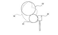
- FIG. 9 is a schematic view when a one-stage gear is adopted instead of the two-stage gear 40 and an external main gear is adopted instead of the main gear 50 having internal teeth.
- a one-stage gear G1 and an external main gear G2 are installed in the same space as in the present embodiment, and these are adjacent to each other along the plane portion 11.
- X be the same number of teeth as the second gear 42 for the one-stage gear G1.
- the diameter of the external gear main gear G2 is smaller than that of the internal gear main gear 50, even if the number of teeth is made as large as possible, it becomes 2Y which is about the same as the actual number of teeth of the main gear 50. .
- the number of teeth of the main gear G2 needs to be 4Y, and the main gear G2 becomes enormous, which makes it difficult to make it compact.
- the steering lock device 1 not only achieves compactness, but also suppresses a decrease in the operating force of the rod 70 due to compactness.
- the main gear 50 is configured as an arcuate gear, so that the stopper 14 is disposed in the space 51 that is the remaining portion of the circumferential region 52 or a part of the rod 70 is disposed. Can be made compact.
- FIG. 10 is a schematic cross-sectional view showing a locked state and an unlocked state of the steering shaft, where (a) shows the locked state and (b) shows the unlocked state.
- an opening O is formed in the steering post SP through which the steering shaft SS is inserted.
- the steering shaft SS is formed with a plurality of (for example, six) protruding portions SSP protruding outward in the radial direction.
- the insertion / extraction part 72 of the rod 70 When the insertion / extraction part 72 of the rod 70 is inserted into the opening O, the insertion / extraction part 72 reaches between the protrusions SSP of the steering shaft SS, and the steering shaft SS can only rotate between the protrusions SSP, Become. In this locked state, since the insertion / extraction part 72 may be in contact with the side wall SSL of the protrusion SSP, it is preferable that the initial operating force when the rod 70 is pulled out is high.
- the width w1 of the first inclined portion 61a is smaller than the width w2 of the second inclined portion 61b.
- the force generated at each of the inclined portions 61a and 61b depends on the distance from the center of rotation to each of the inclined portions 61a and 61b. For this reason, the first inclined portion 61a can pull out the rod 70 with a larger force than the second inclined portion 61b, and an initial operating force that does not hinder the transition to the unlocked state is realized.
- the steering lock device 1 when the main gear 50 is viewed in plan, the entire worm 30 and a part of the rod 70 (the members of at least one of the worm 30 and the rod 70).
- the steering lock device 1 can be downsized because the worm 30 and the rod 70 are arranged so as to overlap the main gear 50 because at least a part thereof is within the circumferential region 52 of the main gear 50. Can be provided.
- the entire structure can be planarized to achieve compactness.
- the two-stage gear 40 including the first gear 41 that meshes with the worm 30 and the second gear 42 that meshes with the main gear 50 having the internal teeth is provided, the two-stage gear 40 can be disposed so as to overlap the main gear 50. (At least a part of the two-stage gear 40 can be arranged in the circumferential region 52), and further compactness can be achieved as compared with the case where both are adjacent to each other along the plane portion 11. Therefore, the steering lock device 1 that can be made compact can be provided.
- the two-stage gear 40 can be arranged on the main gear 50 (in the circumferential region 52), the diameter of the main gear 50 is increased, and the substantial number of teeth of the main gear 50 is increased to reduce the speed.
- the ratio can be increased. Thereby, the fall of the operating force of the rod 70 by compactization can also be suppressed.
- the inclined portion 61 has a width w1 from the rotation center on one rotation direction RD1 side smaller than a width w2 from the rotation center on the other rotation direction RD2 side,
- the force acting on the rod 70 can be improved by reducing the width w1, and the initial force when moving the rod 70 in the direction opposite to the predetermined direction can be increased. it can.
- the rod 70 is in contact with the opening side wall OL of the steering shaft SS and the initial force required when the rod 70 is pulled out to shift to a state where the restriction is released can be realized.
- the main gear 50 is an arc-shaped gear having internal teeth in an arc shape, a space 51 is formed in the remaining portion of the circle, and other members such as a stopper 14 are disposed in the space 51. It is possible to achieve further downsizing.
- this embodiment is not limited to this, and may be changed in the range which does not deviate from the meaning of this embodiment. However, if possible, other techniques may be combined.
- the steering lock device 1 is assumed to have a configuration in which the rod 70 pierces the opening O of the steering post SP.
- the present invention is not limited to this, and the other member is operated by the rod 70 and the other member is opened. It may come to pierce.
- the insertion / extraction part 72 of the rod 70 which concerns on the said embodiment is inserted / extracted in the opening by the side of the steering shaft SS, it will not be restricted to the structure shown in FIG. 10, For example, the structure inserted / extracted to the opening provided in steering shaft SS It may be a different state as long as it can be locked.
- the two-stage gear 40 is adopted from the viewpoint of improving the operating force of the rod 70.
- the present invention is not limited to this.
- a vertically long shape is used.
- a single gear may be used.
- a main gear having substantially semicircular external teeth may be adopted so that the worm 30 and a part of the rod 70 are accommodated in the circumferential region using the remaining space of the circle.
- a main gear having a circular external tooth and a two-stage gear (or a vertically long one-stage gear) may be employed so that all or part of the worm 30 is accommodated in the circumferential region.
- the inclined portion 61 has the first inclined portion 61a and the second inclined portion 61b and has two widths w1 and w2.
- a width may be sufficient and the aspect in which a width changes continuously may be sufficient.
Landscapes
- Engineering & Computer Science (AREA)
- General Engineering & Computer Science (AREA)
- Mechanical Engineering (AREA)
- Power Engineering (AREA)
- Lock And Its Accessories (AREA)
- Gear Transmission (AREA)
Abstract
ステアリングロック装置は、モータシャフトを回転させるモータと、前記モータの前記モータシャフトに取り付けられたウォームと、前記ウォームの回転に伴って回転するメインギアと、前記メインギアと一体に設けられたカム部材と、前記メインギアの回転に伴うカム部材の動作に応じてステアリングシャフト側に設けられた開口に挿抜される挿抜部を有したロッドと、を備え、前記メインギアをその回転軸方向に沿って平面視した場合において、前記ウォームと前記挿抜部との少なくとも一方の部材の少なくとも一部が前記メインギアの円周領域内に収まる。
Description
本開示は、ステアリングロック装置に関する。
従来、ステアリングシャフト側に形成された開口にロッドを挿入することでステアリングをロック状態とし、当該ロッドを抜くことでアンロック状態とするステアリングロック装置が知られている。例えば、特許文献1は、フレーム部材に搭載されモータシャフトを回転させるモータと、モータシャフトに取り付けられたウォームと、ウォームに噛み合いウォームの回転に伴って回転するギアと、このギアと一体に設けられてギアと同軸を中心に回転するカム部材と、カム部材の回転に伴って動作するロッドとを備えたステアリングロック装置を開示する。しかし、このステアリングロック装置は、モータシャフトがフレーム面に対して傾いて配置されており、ギアの回転面もフレーム面に直交する配置となっていることから、立体的な構造となりスペース面で不利である。
特許文献2は、フレーム面に対してモータシャフトの軸方向と各ギアの回転面とを平行に配置したステアリングロック装置を開示する。このステアリングロック装置では、上記配置となることから、各種構成が平面的に配置されることとなり、ステアリングロック装置の全体を平面的な構造とし、スペース面で有利である。
特許文献2よりも更なるコンパンクト化、又は特許文献2に記載のものとは異なる手法によるコンパクト化が研究されている。
本開示は、コンパクト化を図ることが可能なステアリングロック装置に関する。
本開示のステアリングロック装置は、モータと、ウォームと、メインギアと、カム部材と、ロッドとを備えている。モータは、モータシャフトを回転させる。ウォームは、モータのモータシャフトに取り付けられている。メインギアは、ウォームの回転に伴って回転する。カム部材は、メインギアと一体に設けられている。ロッドは、メインギアの回転に伴うカム部材の動作に応じてステアリングシャフト側に設けられた開口に挿抜される挿抜部を有している。さらに、メインギアをその回転軸方向に沿って平面視した場合において、ウォームと挿抜部との少なくとも一方の部材の少なくとも一部がメインギアの円周領域内に収まる。
また、本開示のステアリングロック装置は、モータと、ウォームと、二段ギアと、内歯ギアと、ロッドとを備えている。モータは、フレーム部材に搭載され、フレーム部材の平面部に沿って延びるモータシャフトを回転させる。ウォームは、モータにより回転させられフレーム部材の平面部に沿って延びるモータシャフトに取り付けられている。二段ギアは、ウォームと噛み合う第1ギア、及び、第1ギアの回転軸と同軸の回転軸を有した第2ギアからなり、平面部に沿って回転する。内歯ギアは、二段ギアの第2ギアと噛み合う内歯を有し、平面部に沿って回転する。ロッドは、内歯ギアの回転に伴って、ステアリングシャフトの回転を規制する状態と規制を解除する状態との2状態間を動作する。
本開示のステアリングロック装置は、コンパクト化を図ることができる。
以下、本実施形態を好適な実施形態に沿って説明する。なお、本実施形態は以下に示す実施形態に限られるものではなく、本実施形態の趣旨を逸脱しない範囲において適宜変更可能である。また、以下に示す実施形態においては、一部構成の図示や説明を省略している箇所があるが、省略された技術の詳細については、以下に説明する内容と矛盾が発生しない範囲内において、適宜公知又は周知の技術が適用されていることはいうまでもない。
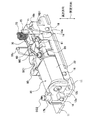
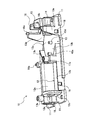
図1は、本実施形態に係るステアリングロック装置の詳細を示す分解斜視図であり、図2は、図1に示した一部構成を互いに組み付けた場合の斜視図である。また、図3、図4及び図5は、図1に示した構成の一部を示す拡大図である。図6は、図2に示した一部構成の上面図である。
図1及び図2に示すように、本実施形態に係るステアリングロック装置1は、概略的に、フレーム部材10と、モータ20と、ウォーム30と、二段ギア40と、メインギア50と、カム部材60と、ロッド70と、モータカバー80と、プリント基板90と、カバー100とから構成されている。
このようなステアリングロック装置1は、モータ20の動作に伴って、ウォーム30、二段ギア40、メインギア50、及びカム部材60を動作させて、ステアリングシャフト(後述する図10の符号SS)が挿通されるステアリングポスト(後述する図10の符号SP)の開口(後述する図10の符号O)に対してロッド70を挿抜させる。ロッド70の挿入状態においてはステアリングシャフトの回転を規制するロック状態となり、ロッド70が抜かれた状態においては規制を解除するアンロック状態となる。以下、各部について詳細に説明する。
図1に示すフレーム部材10は、ステアリングロック装置1の各種の部品を支持する金属製の部材であって、板状の平面部11と、平面部11に対して立設する壁部やねじ穴を有する螺子受け部等とを備えている。
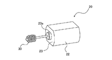
図1及び図3に示すように、モータ20は、モータシャフト21を有し、電力供給を受けてモータシャフト21を回転させるものである。このモータ20は、フレーム部材10に搭載されると共に、モータシャフト21がフレーム部材10の平面部11に沿って延びるように配置されている。
ここで、フレーム部材10には、モータ収容部12(図1参照)が形成されている。モータ収容部12は、モータ20の側面22の形状に合致する一対の湾曲壁12aと、モータ20の前面23及び後面24に接触等する前壁12b及び後壁12cとから構成されている。モータ収容部12の前壁12bには、モータシャフト21が通過する上方開放されたU字溝12dが形成されている。また、モータ収容部12の後壁12cには円形開口12eが形成されている。ここで、図1に示すように、モータ20の後面24にはモータシャフト21を保持する円筒形状の突出部24aを有している。後壁12cの円形開口12eにはモータ20の円筒形状の突出部24aが嵌るようになっている。
図1及び図3に示すウォーム30は、金属又は樹脂からなる螺子状の歯車であって、モータシャフト21の先端側に取り付けられている。図1に示す二段ギア40は、歯数が異なる第1ギア41と第2ギア42とが同軸の回転軸43を有して二段に重なって一体に設けられた金属又は樹脂製の歯車である。二段ギア40のうち第1ギア41はウォーム30に噛み合って配置されており、第2ギア42はメインギア50に噛み合って配置されている。第1ギア41と第2ギア42との歯数は、第1ギア41の方が多く、第2ギア42の方が少なくされている。この二段ギア40は、ウォーム30の回転に伴ってフレーム部材10の平面部11に沿って回転するようになっている。
メインギア50は、二段ギア40の第2ギア42に噛み合う金属又は樹脂製の歯車であり、二段ギア40と同様にフレーム部材10の平面部11に沿って回転する構成となっている。このメインギア50は、多数の内歯が形成されており、多数の内歯が第2ギア42と噛み合うようになっている。
ここで、フレーム部材10には、メインギア収容部13が形成されている。メインギア収容部13は、メインギア50の外形状に沿った壁部13a,13bと底面13cとによって構成されており、これらの壁部13a,13bと底面13cとによって略円形状の溝部が形成され、この溝部にメインギア50が嵌る構成となっている。底面13cは、平面部11と平行であって、平面部11と面一又は異なる高さで形成されている。また、メインギア収容部13の底面13cの中央にはメインギア50の回転軸13dが上方に向けて突出している。このような構成であるため、メインギア50は回転軸13dを中心とし回転軸13d又は壁部13a,13bに摺動するように回転することとなる。なお、メインギア収容部13の底面13cには、図5に示すように、二段ギア40の回転軸40aについても設けられている。この回転軸40aは、回転軸13dよりも第2壁部13b側に設けられており、二段ギア40は、この回転軸40aを中心に回転することとなる。
図1及び図4に示すメインギア50は、円の一部をなす円弧状に内歯を有した円弧状(略半円形状)のギアとなっている。このため、メインギア50は、円の残り部分(略半円形状のメインギア50を除く部分)にスペース51を確保する形状となっており、メインギア50の円周領域52のうちスペース51の部分には、ストッパ14(図1及び図2参照)を形成することができる。このストッパ14は、図1及び図2からも明らかなように、第1壁部13aから回転軸13dに向かってメインギア収容部13内に突出して設けられており、メインギア50に接触して過度な回転を規制するものである。
より詳細に説明すると、メインギア50は、略半円形状となるギアのうち径方向に延びる部位が、解錠側ストッパ部50a及び施錠側ストッパ部50bとして機能するようになっている。また、フレーム部材10のストッパ14についても、解錠側ストッパ部14aと施錠側ストッパ部14bとを有している(図6参照)。メインギア50が後述の回転方向RD1に回転するとロッド70が動作して解錠状態となる。この際、メインギア50の解錠側ストッパ部50aと、ストッパ14の解錠側ストッパ部14aとが接触して、過度なメインギア50等の回転が防止される。同様に、メインギア50が後述の回転方向RD2に回転するとロッド70が動作して施錠状態となる。この際、メインギア50の施錠側ストッパ部50bと、ストッパ14の施錠側ストッパ部14bとが接触して、過度なメインギア50等の回転が防止される(図6に示す状態)。
図1及び図4に示すカム部材60は、メインギア50の回転に伴って平面部11に沿って回転動作する部材であって、本実施形態においてはメインギア50の上部においてメインギア50と一体に設けられている。このカム部材60は、図4に示すように傾斜部61を備えている。傾斜部61は、メインギア50の回転方向に沿って延びると共に平面部11に対して傾斜したものとなっている。この傾斜部61は、傾斜下方側の第1傾斜部61aと傾斜上方側の第2傾斜部61bとからなる。ここで、カム部材60の傾斜下方側が先頭となるように回転する方向を一方の回転方向RD1と称し、一方の回転方向と反対となる方向を他方の回転方向RD2と称する。
図6に示すように、第1傾斜部61aの幅(カム部材60の回転中心からの距離)w1は、第2傾斜部61bの幅w2よりも小さくされている。すなわち、カム部材60の傾斜部61は、一方の回転方向RD1側の幅が、他方の回転方向RD2側の幅よりも小さくされている。
図1に示すロッド70は、板状の金属部材であって、カム部材60の傾斜部61と当接可能な当接部71と、ステアリングシャフトの開口に挿抜される挿抜部72とを備えている。さらに、ステアリングロック装置1は、ロッド70を所定方向に付勢してロッド70をステアリングシャフト側の開口に挿入状態とするためのバネ部材73を備えている。なお、バネ部材73はフレーム部材10に形成された一対の円弧壁15によって保持された状態となっている(図1及び図2参照)。
ここで、図2に示す例においては、ロッド70がステアリングシャフト側の開口に挿入されたロック状態となっている。この状態から、メインギア50が回動し、これに伴ってカム部材60が一方の回転方向RD1に回転したとする。この場合、まずカム部材60の傾斜部61が当接部71に当接する。そして、更にカム部材60が一方の回転方向RD1に回転すると、カム部材60は、バネ部材73の付勢力に抗してロッド70を所定方向とは反対方向に押し上げることとなる。これにより、ロッド70の挿抜部72はステアリングシャフト側の開口から抜かれることとなり、ステアリングロック装置1はアンロック状態となる。
図7は、図1に示したモータカバー80の拡大斜視図であって、(a)はモータカバー80の上方斜視図であり、(b)はモータカバー80の下方斜視図であり、(c)は図7(b)のC矢視図である。図7(a)及び図7(b)に示すモータカバー80は、圧入壁81と、シャフト受け部82とを備えている。
圧入壁81は、モータ20がモータ収容部12に配置された状態において、モータ20の前面23とモータ収容部12の前壁12bとの間に圧入される部位である。この圧入壁81が圧入されることでモータ20は固定されることとなる。この圧入壁81には、第1U字溝81aと、第2U字溝81bと、突起81cとが形成されている。
第1U字溝81aは、圧入壁81の下端から上方に向けて切り欠かれた溝であって、モータ20の前面23に形成された円筒形状の突出部23aが嵌る大きさとなっている。第2U字溝81bは、第1U字溝81a内において、圧入壁81の下端から上方に向けて切り欠かれた溝である。この第2U字溝81bは、モータシャフト21の通過用の溝である。突起81cは、モータカバー80の裏面側から突出しており、圧入壁81が圧入された場合に前壁12bのU字溝12dに嵌り込むようになっている。よって、モータシャフト21は、前壁12bのU字溝12dとモータカバー80の突起81cとにより、その位置が限定されることとなる。
シャフト受け部82は、モータシャフト21の先端を支持する部位であって、モータシャフト21の先端を受け入れるシャフト受け溝82aを有している。シャフト受け溝82aは、フレーム部材10にモータ20を設置した後に圧入壁81の圧入と同時にモータシャフト21の先端が嵌るように、下方が開放された溝となっている。
さらに、図7(a)及び図7(b)に示すモータカバー80は、ギア軸受け部83と、抑え部84とを備えている。ギア軸受け部83は、二段ギア40の回転軸43の受け部となる部位であって、回転軸43が嵌る軸受け孔83aが裏面側に形成されている。抑え部84は、メインギア50とカム部材60との回動に伴う浮き上がりを抑える部位であって、図7(c)に示すように半球状(断面R形状)となる接触部84aを備えている。この接触部84aがメインギア50とカム部材60との回転軸RAを抑える構成となっている。この抑え部84により、メインギア50及びカム部材60が浮いてしまい、メインギア50がメインギア収容部13から離脱してしまうことを防止することとなる。特に、接触部84aのR部分が回転軸RAに当たることにより、たとえメインギア50の回転軸RAが傾いても安定して回転軸RAを抑えることができる。
加えて、モータカバー80は側方に延びる固定部85を備えている。固定部85は裏面側に円形の開口85aが形成されている。この開口85aには、フレーム部材10に形成された円筒突起16aが嵌り込むようになっている。このため、固定部85は、モータカバー80を固定する1手段として機能する。
図1に示すプリント基板90は、モータ20を駆動させる回路等を搭載するものである。ここで、図4に示すように、カム部材60の他方の回転方向RD2側には、マグネット収容部110が一体に形成されている。このマグネット収容部110には、図1に示すようにマグネットMが収容されると共に、マグネットケースMCが取り付けられるようになっている。プリント基板90には、このマグネットMの位置を検知してメインギア50及びカム部材60の回転量を検出可能な回路が搭載されている。
また、プリント基板90には、フレーム部材10に形成された2つの円筒突起16b,16cが嵌り込む貫通孔91,92と、螺子SC1,SC2が挿通される2つの螺子穴93,94とが形成されている。2つの螺子穴93,94は、フレーム部材10に形成された2つの螺子受け部17a,17bと対応しており、2本の螺子SC1,SC2は、プリント基板90の螺子穴93,94を介して、フレーム部材10の螺子受け部17a,17bまで到達して、これらを締結することとなる。
ここで、モータカバー80には、貫通孔86が形成されている。この貫通孔86には、2つの螺子受け部17a,17bのうち、第1の螺子受け部17aが挿入されるようになっている。モータカバー80は、第1の螺子受け部17aが挿入されることで、その位置が固定される。すなわち、第1の螺子受け部17aは、モータカバー80を固定する1手段として機能する。
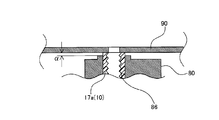
図8は、第1の螺子受け部17a、モータカバー80、及びプリント基板90の積層状態を示す断面図である。図8に示すように、第1の螺子受け部17aは、モータカバー80の貫通孔86に挿入された状態において、その上端がモータカバー80よりも突出した状態となっている(図8においてはαだけ突出している)。ここで、モータカバー80は樹脂製でありフレーム部材10は金属製であることから、上記突出状態とすることによりプリント基板90を剛性の高い金属製のフレーム部材10に取り付けることができる。
図1に示すカバー100は、フレーム部材10と共に各種部品を収納するものであって、側面に複数の開口101が形成されている。この複数の開口101には、フレーム部材10に形成された突起18が嵌り込むようになっており、突起18が開口101に嵌り込むことでカバー100はフレーム部材10に対して取り付けられる。
特に本実施形態に係るステアリングロック装置1は、図6に示すように、メインギア50をその回転軸RA(図4参照)に沿って平面視した場合に、ウォーム30の全部及びロッド70の挿抜部72の一部がメインギア50の円周領域52内に収まるようになっている。なお、本実施形態においては、ウォーム30と挿抜部72との双方が円周領域52内に収まっているが、これに限らず、いずれか一方のみが収まるようになっていてもよい。さらに、ウォーム30は全部が円周領域52内に収まっているが、これに限らず、一部のみが円周領域52内に収まっていてもよい。同様に、挿抜部72は、一部が円周領域52内に収まっているが、これに限らず、全部が円周領域52内に収まっていてもよい。
次に、本実施形態に係るステアリングロック装置1の作用等について説明する。まず、本実施形態に係るステアリングロック装置1は以下のような理由からコンパクト化された構造となる。
本実施形態に係るステアリングロック装置1は、メインギア50を平面視した場合に、ウォーム30の全部と挿抜部72の一部とがメインギア50の円周領域52内に収まっている。このため、メインギア50に重なるようにウォーム30とロッド70とを配置させることとなり、コンパクト化を図っている。
特に、本実施形態においてウォーム30は、図2からも明らかなように、モータカバー80よりも所定方向側に位置しており、高さ方向においてカム部材60の上端面を超えることがない。すなわち、ウォーム30は、メインギア50の円周領域52内に収まり、且つ、カム部材60の上端面よりも高さが低く配置されることから、ウォーム30をメインギア50の円周領域52に重なるように配置したとしても、厚みを増加させることなく、一層のコンパクト化を図っている。
更に、モータシャフト21が平面部11に沿って延びると共に、二段ギア40及びメインギア50が平面部11に沿って回転することから、全体的に平面的な構造とし、コンパクト化を図っている。
加えて、内歯を有したメインギア50を備えるため、メインギア50の円周領域52内に二段ギア40の一部(図6では一部であるが全部でも可)を配置することとなり、両者を平面部11に沿って隣り合わせる場合と比較すると、更なるコンパクト化を図ることとなる。
さらに、本実施形態においてはメインギア50上に二段ギア40を配置してコンパクト化を図ることができることから、メインギア50の径を大きくすることにもつながる。このため、メインギア50の実質的な歯数(メインギア50が円形歯車であったとすると存在するはずの歯数)を多くすることができ、減速比を大きくすることも可能となる。これにより、コンパクト化に伴うロッド70の動作力低下についても抑制することとなる。
一例を説明すると、本実施形態において二段ギア40の第1ギア41は歯数が2X(Xは任意の整数)であり、第2ギア42の歯数がXとなっているとする。さらに、メインギア50は円弧状歯車であることから、実際の歯数はYであるが、メインギア50が円形歯車であったと仮定したときの実質的な歯数は例えば2Yとなっている。よって、このような歯数であると、減速比は(2X/1)×(2Y/X)=4Yとすることができる。
図9は、二段ギア40に代えて一段の歯車を採用し、且つ、内歯を有するメインギア50に代えて外歯のメインギアを採用したときの概略図である。図9に示すように、本実施形態と同様のスペース内に一段の歯車G1と、外歯のメインギアG2とを設置し、これらを平面部11に沿って隣り合わせたとする。さらに、一段の歯車G1については第2ギア42と同様の歯数であるXとしたとする。この場合において、外歯のメインギアG2については内歯のメインギア50よりも径が小さくなることから、歯数を極力多く構成したとしてもメインギア50の実質歯数と同程度の2Yとなる。このため、減速比は(X/1)×(2Y/X)=2Yとなり、ロッドの動作力は本実施形態と比較すると例えば半分に低下してしまう。一方、本実施形態と同程度の減速比を実現するためには、メインギアG2の歯数を4Yとする必要があり、メインギアG2の巨大化を招くことから、コンパクト化が困難となる。
以上より、本実施形態に係るステアリングロック装置1は、コンパクト化を図るだけでなく、コンパクト化に伴うロッド70の動作力の低下についても抑制することとなる。
また、本実施形態においてはメインギア50を円弧状歯車として構成しているため、円周領域52の残り部分となるスペース51にストッパ14を配置したり、ロッド70の一部を配置したりすることができ、コンパクト化を図っている。
さらに、本実施形態においてはロッド70を引き抜くときの初期動作力を向上させる構成となっている。図10は、ステアリングシャフトのロック状態とアンロック状態とを示す概略断面図であって、(a)はロック状態を示し、(b)はアンロック状態を示している。図10(a)及び図10(b)に示すように、ステアリングシャフトSSが挿通されるステアリングポストSPには開口Oが形成されている。ステアリングシャフトSSは、径方向外側に突出する複数(例えば6つ)の突起部SSPが形成されている。開口Oにロッド70の挿抜部72が挿入されると、挿抜部72はステアリングシャフトSSの突起部SSP間まで到達し、ステアリングシャフトSSは突起部SSP間での回転動作しかできず、ロック状態となる。このロック状態において、挿抜部72は、突起部SSPの側壁SSLに接触している場合もあり得ることから、ロッド70を引き抜く際の初期動作力は高いことが好ましい。
ここで、本実施形態においては、図6に示すように、第1傾斜部61aの幅w1が第2傾斜部61bの幅w2よりも小さくされている。また、各傾斜部61a,61bにて発生する力(ロッド70を引き上げる力)は回転中心から各傾斜部61a,61bまでの距離に依存する。このため、第1傾斜部61aの方が第2傾斜部61bよりも大きな力でロッド70を引き抜くことができ、アンロック状態への移行に支障がない初期動作力を実現することとなる。
このようにして、本実施形態に係るステアリングロック装置1によれば、メインギア50を平面視した場合、ウォーム30の全部及びロッド70の一部(ウォーム30とロッド70との少なくとも一方の部材の少なくとも一部でも可)がメインギア50の円周領域52に収まるため、メインギア50に対してウォーム30やロッド70を重ねて配置することとなり、コンパクト化を図ることが可能なステアリングロック装置1を提供することができる。
また、モータシャフト21が平面部11に沿って延びると共に、二段ギア40及びメインギア50の双方が平面部11に沿って回転するため、全体を平面的な構造としコンパクト化を図ることができる。さらに、ウォーム30に噛み合う第1ギア41と内歯を有するメインギア50に噛み合う第2ギア42とからなる二段ギア40を備えているため、メインギア50に重なって二段ギア40を配置でき(円周領域52内に二段ギア40の少なくとも一部を配置でき)、両者を平面部11に沿って隣り合わせる場合と比較すると、更なるコンパクト化を図ることができる。従って、コンパクト化を図ることが可能なステアリングロック装置1を提供することができる。
しかも、二段ギア40をメインギア50上(円周領域52内)に配置できることから、メインギア50の径を大きくすることにもつながり、メインギア50の実質的な歯数を多くして減速比を高くすることが可能となる。これにより、コンパクト化によるロッド70の動作力の低下も抑えることができる。
さらに、傾斜部61は、一方の回転方向RD1側における回転中心からの幅w1が、他方の回転方向RD2側における回転中心からの幅w2よりも小さくされているため、傾斜部61を一方の回転方向RD1側に回動させる際には、幅w1が小さいことによりロッド70に作用する力の向上を図り、ロッド70を所定方向と反対方向に移動させる際の初期的な力を大きくすることができる。これにより、ロッド70がステアリングシャフトSSの開口側壁OL等に接触しており、ロッド70を引き抜いて規制を解除する状態へ移行するときに必要となる初期的な力を実現することができる。
加えて、メインギア50は、円弧状に内歯を有する円弧状ギアであるため、円の残り部分にはスペース51を作ることとなり、このスペース51にストッパ14を設けるなど、他の部材を配置でき、一層のコンパクト化を図ることができる。
以上、本実施形態に係るステアリングロック装置を実施形態に基づいて説明したが、本実施形態はこれに限定されるものではなく、本実施形態の趣旨を逸脱しない範囲で、変更を加えてもよいし、可能であれば他の技術を組み合わせてもよい。
例えば、上記実施形態においてステアリングロック装置1は、ロッド70がステアリングポストSPの開口Oに突き刺さる構成を想定しているが、これに限らず、ロッド70により他部材を動作させ、その他部材が開口Oに突き刺さるようになっていてもよい。さらに、上記実施形態に係るロッド70の挿抜部72は、ステアリングシャフトSS側の開口に挿抜されれば図10に示した構成に限らず、例えばステアリングシャフトSSに設けられた開口に挿抜される構成であってもよいし、ロック状態とできれば他の構成であってもよい。
また、本実施形態においては、ロッド70の動作力を向上させる観点から二段ギア40を採用しているが、これに限らず、例えば二段ギア40に代えて、例えば高さ方向に縦長となる一段ギアを採用してもよい。また、略半円形状の外歯を有するメインギアを採用し、円の残りのスペースを利用してウォーム30やロッド70の一部等を円周領域内に収めるようにしてもよい。さらには、円形形状の外歯を有するメインギアと二段ギア(又は縦長の一段ギア)を採用し、ウォーム30の全部又は一部を円周領域内に収めるようにしてもよい。
加えて、本実施形態において傾斜部61は、第1傾斜部61aと第2傾斜部61bとを有して2通りの幅w1,w2となっているが、これに限らず、3通り以上の幅であってもよいし、幅が連続的に変化する態様であってもよい。
本出願は、2017年1月31日出願の日本特許出願(特願2017-015452)、に基づくものであり、その内容はここに参照として取り込まれる。
10 :フレーム部材
11 :平面部
14 :ストッパ
20 :モータ
21 :モータシャフト
30 :ウォーム
40 :二段ギア
41 :第1ギア
42 :第2ギア
43 :回転軸
50 :メインギア
51 :スペース
52 :円周領域
60 :カム部材
61 :傾斜部
61a :第1傾斜部
61b :第2傾斜部
70 :ロッド
71 :当接部
72 :挿抜部
RD1 :一方の回転方向
RD2 :他方の回転方向
SS :ステアリングシャフト
11 :平面部
14 :ストッパ
20 :モータ
21 :モータシャフト
30 :ウォーム
40 :二段ギア
41 :第1ギア
42 :第2ギア
43 :回転軸
50 :メインギア
51 :スペース
52 :円周領域
60 :カム部材
61 :傾斜部
61a :第1傾斜部
61b :第2傾斜部
70 :ロッド
71 :当接部
72 :挿抜部
RD1 :一方の回転方向
RD2 :他方の回転方向
SS :ステアリングシャフト
Claims (4)
- モータシャフトを回転させるモータと、
前記モータの前記モータシャフトに取り付けられたウォームと、
前記ウォームの回転に伴って回転するメインギアと、
前記メインギアと一体に設けられたカム部材と、
前記メインギアの回転に伴うカム部材の動作に応じてステアリングシャフト側に設けられた開口に挿抜される挿抜部を有したロッドと、を備え、
前記メインギアをその回転軸方向に沿って平面視した場合において、前記ウォームと前記挿抜部との少なくとも一方の部材の少なくとも一部が前記メインギアの円周領域内に収まるステアリングロック装置。 - フレーム部材に搭載され、前記フレーム部材の平面部に沿って延びるモータシャフトを回転させるモータと、
前記モータの前記モータシャフトに取り付けられたウォームと、
前記ウォームと噛み合う第1ギア、及び、前記第1ギアの回転軸と同軸の回転軸を有した第2ギアを有し、前記平面部に沿って回転する二段ギアと、
前記二段ギアの第2ギアと噛み合う内歯を有し、前記平面部に沿って回転するメインギアと、
前記メインギアの回転に伴って、ステアリングシャフトの回転を規制する状態と規制を解除する状態との2つの状態間を遷移するロッドと、
を備えるステアリングロック装置。 - 前記メインギアの回転に伴って前記平面部に沿って回転動作すると共に回転方向に延び且つ前記平面部に対して傾斜した傾斜部が形成されたカム部材と、
前記ロッドを所定方向に付勢してステアリングシャフトの回転を規制する状態とするバネ部材と、をさらに備え、
前記ロッドは、前記傾斜部に当接可能な当接部を有し、前記カム部材の前記傾斜部が前記当接部に当接した状態で前記カム部材が一方の回転方向に回転動作することで、前記所定方向と反対方向に移動させられて規制を解除する状態へと遷移し、
前記カム部材の前記傾斜部は、前記一方の回転方向側における回転中心からの幅が、前記一方の回転方向と反対側となる他方の回転方向側における回転中心からの幅よりも小さい請求項2に記載のステアリングロック装置。 - 前記メインギアは、円の一部をなす円弧状に歯を有した円弧状ギアである請求項1から請求項3のいずれか1項に記載のステアリングロック装置。
Priority Applications (4)
| Application Number | Priority Date | Filing Date | Title |
|---|---|---|---|
| CN201880009045.1A CN110267852B (zh) | 2017-01-31 | 2018-01-31 | 转向锁定装置 |
| EP23161010.6A EP4219248B1 (en) | 2017-01-31 | 2018-01-31 | Steering lock device |
| EP18747837.5A EP3578425B1 (en) | 2017-01-31 | 2018-01-31 | Steering lock device |
| US16/521,440 US11628804B2 (en) | 2017-01-31 | 2019-07-24 | Steering lock device |
Applications Claiming Priority (2)
| Application Number | Priority Date | Filing Date | Title |
|---|---|---|---|
| JP2017015452A JP6807762B2 (ja) | 2017-01-31 | 2017-01-31 | ステアリングロック装置 |
| JP2017-015452 | 2017-01-31 |
Related Child Applications (1)
| Application Number | Title | Priority Date | Filing Date |
|---|---|---|---|
| US16/521,440 Continuation US11628804B2 (en) | 2017-01-31 | 2019-07-24 | Steering lock device |
Publications (1)
| Publication Number | Publication Date |
|---|---|
| WO2018143309A1 true WO2018143309A1 (ja) | 2018-08-09 |
Family
ID=63040769
Family Applications (1)
| Application Number | Title | Priority Date | Filing Date |
|---|---|---|---|
| PCT/JP2018/003309 Ceased WO2018143309A1 (ja) | 2017-01-31 | 2018-01-31 | ステアリングロック装置 |
Country Status (5)
| Country | Link |
|---|---|
| US (1) | US11628804B2 (ja) |
| EP (2) | EP4219248B1 (ja) |
| JP (1) | JP6807762B2 (ja) |
| CN (1) | CN110267852B (ja) |
| WO (1) | WO2018143309A1 (ja) |
Families Citing this family (2)
| Publication number | Priority date | Publication date | Assignee | Title |
|---|---|---|---|---|
| JP7126877B2 (ja) * | 2018-06-22 | 2022-08-29 | 株式会社山田製作所 | ステアリング装置 |
| CN110581458A (zh) * | 2019-10-25 | 2019-12-17 | 安徽国信电缆科技股份有限公司 | 一种电缆敷设设备 |
Citations (5)
| Publication number | Priority date | Publication date | Assignee | Title |
|---|---|---|---|---|
| JP2004092867A (ja) * | 2002-09-03 | 2004-03-25 | Hosiden Corp | 歯車固定機構 |
| JP2013542124A (ja) | 2010-10-07 | 2013-11-21 | ヴァレオ、ズィッヒャーハイトジステメ、ゲゼルシャフト、ミット、ベシュレンクテル、ハフツング | ステアリングコラムをロック/アンロックする電気式盗難防止装置 |
| JP2015532235A (ja) * | 2012-10-04 | 2015-11-09 | ユーシン ドイチュラント ツーガングスジュステーメ ゲゼルシャフト ミット ベシュレンクテル ハフツング | 自動車用の電動ステアリングコラムロック装置 |
| JP2016074425A (ja) * | 2011-10-10 | 2016-05-12 | ダェドン シーオー., エルティディー.Dae Dong Co., Ltd. | 車両の電動式ステアリングロック装置及びその組み立て方法 |
| JP2017015452A (ja) | 2015-06-29 | 2017-01-19 | 株式会社日立ハイテクノロジーズ | 自動分析装置 |
Family Cites Families (13)
| Publication number | Priority date | Publication date | Assignee | Title |
|---|---|---|---|---|
| DE10133408A1 (de) * | 2000-07-19 | 2002-05-02 | Marquardt Gmbh | Verriegelungseinrichtung, insbesondere für ein Kraftfahrzeug |
| DE10109609C1 (de) * | 2001-02-28 | 2002-10-10 | Huf Huelsbeck & Fuerst Gmbh | Schloß, insbesondere zum Verriegeln der Lenkspindel eines Kraftfahrzeugs |
| ITTO20010663A1 (it) * | 2001-07-06 | 2003-01-06 | Trw Italia Spa | Bloccasterzo elettrico perfezionato per veicoli. |
| JP2006067694A (ja) * | 2004-08-26 | 2006-03-09 | Jidosha Denki Kogyo Co Ltd | アクチュエータ装置 |
| US20060053921A1 (en) | 2004-08-26 | 2006-03-16 | Jidosha Denki Kogyo Co., Ltd. | Actuator apparatus |
| EP1967424B1 (de) * | 2007-03-09 | 2010-11-10 | Valeo Sicherheitssysteme GmbH | Motorisierte Lenkverrieglungsvorrichtung |
| KR100868167B1 (ko) * | 2007-10-04 | 2008-11-12 | 지엠대우오토앤테크놀로지주식회사 | X-암 타입 레귤레이터의 듀얼 스톱핑 기구 |
| JP5260358B2 (ja) * | 2009-03-06 | 2013-08-14 | 株式会社ユーシン | 電動ステアリングロック装置 |
| JP5260360B2 (ja) * | 2009-03-06 | 2013-08-14 | 株式会社ユーシン | 電動ステアリングロック装置 |
| JP5268780B2 (ja) * | 2009-05-27 | 2013-08-21 | 株式会社ユーシン | 電動ステアリングロック装置 |
| CN202186352U (zh) * | 2011-08-24 | 2012-04-11 | 马夸特开关(上海)有限公司 | 电子转向柱锁定系统的锁止装置 |
| CN104386019A (zh) * | 2014-11-21 | 2015-03-04 | 苏州华昌机电有限公司 | 一种汽车电子转向柱锁及应用其的汽车 |
| US10472869B2 (en) * | 2015-03-12 | 2019-11-12 | Strattec Security Corporation | Powered latch mechanism with manual release |
-
2017
- 2017-01-31 JP JP2017015452A patent/JP6807762B2/ja active Active
-
2018
- 2018-01-31 EP EP23161010.6A patent/EP4219248B1/en active Active
- 2018-01-31 CN CN201880009045.1A patent/CN110267852B/zh active Active
- 2018-01-31 WO PCT/JP2018/003309 patent/WO2018143309A1/ja not_active Ceased
- 2018-01-31 EP EP18747837.5A patent/EP3578425B1/en active Active
-
2019
- 2019-07-24 US US16/521,440 patent/US11628804B2/en active Active
Patent Citations (6)
| Publication number | Priority date | Publication date | Assignee | Title |
|---|---|---|---|---|
| JP2004092867A (ja) * | 2002-09-03 | 2004-03-25 | Hosiden Corp | 歯車固定機構 |
| JP2013542124A (ja) | 2010-10-07 | 2013-11-21 | ヴァレオ、ズィッヒャーハイトジステメ、ゲゼルシャフト、ミット、ベシュレンクテル、ハフツング | ステアリングコラムをロック/アンロックする電気式盗難防止装置 |
| JP2016074425A (ja) * | 2011-10-10 | 2016-05-12 | ダェドン シーオー., エルティディー.Dae Dong Co., Ltd. | 車両の電動式ステアリングロック装置及びその組み立て方法 |
| JP2015532235A (ja) * | 2012-10-04 | 2015-11-09 | ユーシン ドイチュラント ツーガングスジュステーメ ゲゼルシャフト ミット ベシュレンクテル ハフツング | 自動車用の電動ステアリングコラムロック装置 |
| JP2015532234A (ja) | 2012-10-04 | 2015-11-09 | ユーシン ドイチュラント ツーガングスジュステーメ ゲゼルシャフト ミット ベシュレンクテル ハフツング | 自動車用の電動ステアリングコラムロック装置 |
| JP2017015452A (ja) | 2015-06-29 | 2017-01-19 | 株式会社日立ハイテクノロジーズ | 自動分析装置 |
Non-Patent Citations (1)
| Title |
|---|
| See also references of EP3578425A4 |
Also Published As
| Publication number | Publication date |
|---|---|
| EP4219248B1 (en) | 2024-11-20 |
| JP6807762B2 (ja) | 2021-01-06 |
| US11628804B2 (en) | 2023-04-18 |
| EP3578425B1 (en) | 2025-07-30 |
| EP4219248A1 (en) | 2023-08-02 |
| US20190344751A1 (en) | 2019-11-14 |
| CN110267852B (zh) | 2022-02-11 |
| EP3578425A1 (en) | 2019-12-11 |
| JP2018122679A (ja) | 2018-08-09 |
| CN110267852A (zh) | 2019-09-20 |
| EP3578425A4 (en) | 2020-08-19 |
Similar Documents
| Publication | Publication Date | Title |
|---|---|---|
| JP6187807B2 (ja) | ボールねじ装置 | |
| US8640512B2 (en) | Lock structure for electronic device | |
| WO2018143309A1 (ja) | ステアリングロック装置 | |
| JP2010031562A (ja) | キー装置 | |
| CN101372220B (zh) | 转向锁定装置 | |
| JP2008539352A (ja) | 電気機械式ロック装置 | |
| JP5268780B2 (ja) | 電動ステアリングロック装置 | |
| JP2015007391A (ja) | 電動圧縮機 | |
| JP2007269176A (ja) | ステアリングロック装置 | |
| JP2006130172A (ja) | 遊技機用の回転表示装置及びその組み立て方法 | |
| JP2008051174A (ja) | 自動変速機のパーキング機構 | |
| JP4763578B2 (ja) | 電動ステアリングロック装置 | |
| JP4698969B2 (ja) | バッテリー着脱装置 | |
| TW201126832A (en) | Connector assembly for coupling circuit boards | |
| KR20230024800A (ko) | 펌프 | |
| JP2014228045A (ja) | ボールねじ装置 | |
| JP2009131514A (ja) | 遊技機用施錠装置及びそれを備えた遊技機 | |
| JP2009179232A (ja) | ステアリングロック装置 | |
| JP6878199B2 (ja) | ステアリングロック装置 | |
| JP2009096299A (ja) | ステアリングロック装置 | |
| JP2005245172A (ja) | ファンモータ | |
| JP7133993B2 (ja) | 電動アクチュエータ | |
| JP2005180959A (ja) | 回転検出装置 | |
| JP2005141322A (ja) | カード用コネクタ装置 | |
| JP2022128853A (ja) | ステアリングロック装置 |
Legal Events
| Date | Code | Title | Description |
|---|---|---|---|
| 121 | Ep: the epo has been informed by wipo that ep was designated in this application |
Ref document number: 18747837 Country of ref document: EP Kind code of ref document: A1 |
|
| NENP | Non-entry into the national phase |
Ref country code: DE |
|
| ENP | Entry into the national phase |
Ref document number: 2018747837 Country of ref document: EP Effective date: 20190902 |
|
| WWG | Wipo information: grant in national office |
Ref document number: 2018747837 Country of ref document: EP |